EP4333176A1 - Household energy storage system and module fixing structure thereof - Google Patents
Household energy storage system and module fixing structure thereof Download PDFInfo
- Publication number
- EP4333176A1 EP4333176A1 EP23185109.8A EP23185109A EP4333176A1 EP 4333176 A1 EP4333176 A1 EP 4333176A1 EP 23185109 A EP23185109 A EP 23185109A EP 4333176 A1 EP4333176 A1 EP 4333176A1
- Authority
- EP
- European Patent Office
- Prior art keywords
- modules
- module
- positioning
- fixing
- fixing member
- Prior art date
- Legal status (The legal status is an assumption and is not a legal conclusion. Google has not performed a legal analysis and makes no representation as to the accuracy of the status listed.)
- Granted
Links
Images



Classifications
-
- H—ELECTRICITY
- H01—ELECTRIC ELEMENTS
- H01M—PROCESSES OR MEANS, e.g. BATTERIES, FOR THE DIRECT CONVERSION OF CHEMICAL ENERGY INTO ELECTRICAL ENERGY
- H01M50/00—Constructional details or processes of manufacture of the non-active parts of electrochemical cells other than fuel cells, e.g. hybrid cells
- H01M50/20—Mountings; Secondary casings or frames; Racks, modules or packs; Suspension devices; Shock absorbers; Transport or carrying devices; Holders
- H01M50/204—Racks, modules or packs for multiple batteries or multiple cells
- H01M50/207—Racks, modules or packs for multiple batteries or multiple cells characterised by their shape
- H01M50/209—Racks, modules or packs for multiple batteries or multiple cells characterised by their shape adapted for prismatic or rectangular cells
-
- H—ELECTRICITY
- H01—ELECTRIC ELEMENTS
- H01G—CAPACITORS; CAPACITORS, RECTIFIERS, DETECTORS, SWITCHING DEVICES, LIGHT-SENSITIVE OR TEMPERATURE-SENSITIVE DEVICES OF THE ELECTROLYTIC TYPE
- H01G2/00—Details of capacitors not covered by a single one of groups H01G4/00-H01G11/00
- H01G2/02—Mountings
- H01G2/04—Mountings specially adapted for mounting on a chassis
-
- H—ELECTRICITY
- H01—ELECTRIC ELEMENTS
- H01M—PROCESSES OR MEANS, e.g. BATTERIES, FOR THE DIRECT CONVERSION OF CHEMICAL ENERGY INTO ELECTRICAL ENERGY
- H01M50/00—Constructional details or processes of manufacture of the non-active parts of electrochemical cells other than fuel cells, e.g. hybrid cells
- H01M50/20—Mountings; Secondary casings or frames; Racks, modules or packs; Suspension devices; Shock absorbers; Transport or carrying devices; Holders
- H01M50/258—Modular batteries; Casings provided with means for assembling
-
- H—ELECTRICITY
- H01—ELECTRIC ELEMENTS
- H01M—PROCESSES OR MEANS, e.g. BATTERIES, FOR THE DIRECT CONVERSION OF CHEMICAL ENERGY INTO ELECTRICAL ENERGY
- H01M50/00—Constructional details or processes of manufacture of the non-active parts of electrochemical cells other than fuel cells, e.g. hybrid cells
- H01M50/20—Mountings; Secondary casings or frames; Racks, modules or packs; Suspension devices; Shock absorbers; Transport or carrying devices; Holders
- H01M50/262—Mountings; Secondary casings or frames; Racks, modules or packs; Suspension devices; Shock absorbers; Transport or carrying devices; Holders with fastening means, e.g. locks
-
- H—ELECTRICITY
- H01—ELECTRIC ELEMENTS
- H01M—PROCESSES OR MEANS, e.g. BATTERIES, FOR THE DIRECT CONVERSION OF CHEMICAL ENERGY INTO ELECTRICAL ENERGY
- H01M50/00—Constructional details or processes of manufacture of the non-active parts of electrochemical cells other than fuel cells, e.g. hybrid cells
- H01M50/20—Mountings; Secondary casings or frames; Racks, modules or packs; Suspension devices; Shock absorbers; Transport or carrying devices; Holders
- H01M50/289—Mountings; Secondary casings or frames; Racks, modules or packs; Suspension devices; Shock absorbers; Transport or carrying devices; Holders characterised by spacing elements or positioning means within frames, racks or packs
-
- Y—GENERAL TAGGING OF NEW TECHNOLOGICAL DEVELOPMENTS; GENERAL TAGGING OF CROSS-SECTIONAL TECHNOLOGIES SPANNING OVER SEVERAL SECTIONS OF THE IPC; TECHNICAL SUBJECTS COVERED BY FORMER USPC CROSS-REFERENCE ART COLLECTIONS [XRACs] AND DIGESTS
- Y02—TECHNOLOGIES OR APPLICATIONS FOR MITIGATION OR ADAPTATION AGAINST CLIMATE CHANGE
- Y02E—REDUCTION OF GREENHOUSE GAS [GHG] EMISSIONS, RELATED TO ENERGY GENERATION, TRANSMISSION OR DISTRIBUTION
- Y02E60/00—Enabling technologies; Technologies with a potential or indirect contribution to GHG emissions mitigation
- Y02E60/10—Energy storage using batteries
Definitions
- the present application relates to the field of energy storage technology, and in particular to a household energy storage system and a module fixing structure thereof.
- the stacked modular design is usually used in the above household energy storage systems.
- the modular design is implemented as dividing the entire household energy storage system into multiple modules based on functions, while the stacked modular design is implemented as sequentially stacking the multiple modules in a height direction from bottom to top.
- the modules As the height of the stacked modules increases, the modules generally are required to be fixed in order to ensure the stability of the system.
- the conventional fixing manners are complex, which is not convenient for installation and maintenance.
- the object of the present application is to provide a household energy storage system and a module fixing structure thereof, to improve the convenience of installation and maintenance.
- a module fixing structure of a household energy storage system includes:
- the number of the first fixing member is at least two; and the at least two first fixing members stretch across a same number of modules; and/or, the at least two first fixing members stretch across different numbers of modules.
- the stacking direction in which the N modules are stacked is a vertical direction and/or a horizontal direction.
- each of the multiple modules is of a rectangular cuboid shape
- the vertical direction is a height direction of the modules
- the horizontal direction is a length direction and/or a width direction of the modules.
- two adjacent modules of the multiple modules fit with each other by positioning in the stacking direction.
- one of the two adjacent modules is provided with at least one positioning groove
- the other of the two adjacent modules is provided with at least one positioning member
- the positioning member and the positioning groove fit with each other by positioning.
- the number of the at least one positioning member is two or more, and the number of the at least one positioning groove is two or more; at least one of the two or more positioning members is a first positioning member, at least one of the two or more positioning grooves is a first positioning groove, and the first positioning member and the first positioning groove fit with each other by positioning;
- the stacking direction is a vertical direction
- the first positioning member is a handle
- the first positioning groove is a handle groove
- the handle is arranged at a top of the other of the two adjacent modules
- the handle groove is arranged at a bottom of the one of the two adjacent modules
- the second positioning member is a positioning rod
- the second positioning groove is a positioning rod groove
- the first fixing member is fixedly connected to the modules in a detachable manner.
- the module is provided with a first mounting notch
- the first mounting notch and the first fixing member fit with each other by positioning and/or the first fixing member and the modules on which the first fixing member is located are flush with each other, and the first fixing member is fixed at the first mounting notch.
- the first fixing member and the modules on which the first fixing member is located are flush with each other
- at least one of the modules is provided with a first flange in a circumferential direction
- the first flange has a first flange notch
- the first fixing member includes a first fixing plate and a first protruding portion provided on the first fixing plate; where the first fixing plate is fixed at the first mounting notch, and the first fixing plate and the modules on which the first fixing member is located are flush with each other; the first protruding portion is arranged at the first flange notch, and the first protruding portion and the first flange are flush with each other and abutted to each other to form a closed loop structure.
- the module fixing structure further includes a second fixing member, where the second fixing member is used to fixedly connect two adjacent modules of the multiple modules in the stacking direction.
- each of the two adjacent modules of the multiple modules is provided with a second mounting notch, the second mounting notch and the second fixing member fit with each other by positioning, and/or the second fixing member and the two adjacent modules to which the second fixing member is connected are flush with each other; and the second fixing member is fixed at the second mounting notch.
- the second fixing member and the two adjacent modules to which the second fixing member is connected are flush with each other, at least one of the two adjacent modules is provided with a second flange in a circumferential direction, the second flange has a second flange notch; and the second fixing member includes a second fixing plate and a second protruding portion provided on the second fixing plate; where the second fixing plate is fixed at the second mounting notch, and the second fixing plate and the two adjacent modules to which the second fixing plate is connected are flush with each other; the second protruding portion is arranged at the second flange notch, and the second protruding portion and the second flange at which the second protruding portion is arranged are flush with each other and abutted to each other to form a closed loop structure.
- At least two of the modules are functional modules and at least one of the modules is a structural module; or, at least one of the modules is a functional module and at least two of the modules are structural modules; or, each of the modules is a functional module; and where the functional module is an energy storage module, a power control module, an inverter module, a photovoltaic power generation module or a heat dissipation module, and the structural module is a base or a top cover.
- the household energy storage system includes the module fixing structure according to any one of the above embodiments.
- the modules are stacked in at least one stacking direction
- the first fixing member stretches across M modules in the stacking direction in which N modules are stacked, and only two ends of the first fixing member are fixed to two of the modules, respectively, N is a positive integer greater than or equal to 3
- M is a positive integer less than or equal to N-2.
- the first fixing member stretches across the M modules in the stacking direction in which N modules are stacked, which effectively reduces the number of the first fixing member and the number of fixed connections. Therefore, with the above module fixing structure, the convenience of installation and maintenance is improved.
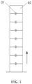
- FIG. 1 in the conventional household energy storage system, eight modules 02 are stacked in sequence in a vertical direction, where the vertical direction is shown by the arrow in FIG. 1 .
- Two adjacent modules 02 are fixedly connected through a fixing member 01. Specifically, one of the two adjacent modules 02 is fixedly connected to one end of the fixing member 01 and the other of the two adjacent modules 02 is fixedly connected to the other end of the fixing member 01.
- the household energy storage system is usually installed by a third party or by the customer, and the above fixing structure increases the complexity of on-site installation and on-site maintenance.
- a module fixing structure of a household energy storage system is provided according to embodiments of the present application.
- the module fixing structure includes multiple modules 3 and at least one first fixing member 1.
- the modules 3 are stacked in at least one stacking direction; the first fixing member 1 stretches across M modules 3 of the modules 3 in a stacking direction in which N modules 3 are stacked, and only two ends of the first fixing member 1 are fixed to two of the multiple modules 3, respectively.
- N is a positive integer greater than or equal to 3
- M is a positive integer less than or equal to N-2.
- the first fixing member 1 includes two fixing portions 111 and a stretching-across portion 112 located between the two fixing portions 111.
- One fixing portion 111 is fixedly connected to one end of the stretching-across portion 112, and the other fixing portion 111 is fixedly connected to the other end of the stretching-across portion 112, and the fixing portion 111 is fixedly connected to the corresponding module 3.
- the first fixing member 1 may be a one-piece structure or a split structure, depending on the actual needs.
- the first fixing member 1 stretches across the M modules 3 in the stacking direction in which N modules 3 are stacked, which effectively reduces the number of the first fixing member 1 and the number of fixed connections. Therefore, with the above module fixing structure, the convenience of installation and maintenance is improved.
- the number of the first fixing member 1 may be one, or two or more. In a case that the number of the first fixing member 1 is at least two, the at least two first fixing members 1 may stretch across the same number of modules 3, and/or, the at least two first fixing members 1 may stretch across different numbers of modules 3.
- the number of modules 3 across which each of first fixing members 1 stretches is selected according to actual needs, so that the form of fixing can be varied according to the actual situation without changing the number of fixing connections, which improves flexibility and further improves the convenience of installation and maintenance, thereby improving adaptability to complex installation environments.
- the above stacking direction may be one, or two or more, depending on the actual needs.
- the specific direction of the above stacking direction is also selected according to actual needs.
- the stacking direction is a vertical direction and/or a horizontal direction. It is understood that the horizontal direction is perpendicular to the vertical direction.
- the stacking direction in which N modules 3 are stacked is a vertical direction and/or a horizontal direction.
- the above modules 3 are usually of a rectangular cuboid shape, the above vertical direction is a height direction of the modules 3, and the above horizontal direction is a length direction and/or a width direction of the modules 3.
- the stacking direction in which N modules 3 are stacked is the height direction of the modules 3, and/or the length direction of the modules 3, and/or the width direction of the modules 3.
- the arrow lines shown in FIGS. 2 , 3 , 10 and 11 indicate the vertical direction
- the solid arrow line in FIG. 6 indicates the length direction of the modules 3
- the dashed arrow line in FIG. 6 indicates the width direction of the modules 3
- the horizontal arrow line in FIG. 12 indicates the horizontal direction
- the vertical arrow line in FIG. 12 indicates the vertical direction.
- two adjacent modules 3 fit with each other by positioning in the stacking direction.
- the specific structure of the fitting and positioning of the two modules 3 is selected according to actual needs.
- one of the two adjacent modules 3 is provided with at least one positioning groove
- the other of the two adjacent modules 3 is provided with at least one positioning member
- the positioning member and the positioning groove fit with each other by positioning.
- the specific structure and the specific number of the above positioning member and the positioning groove may be selected according to actual needs, which are not limited in the embodiment.
- two or more positioning members and two or more positioning grooves are provided; where at least one of the positioning members is a first positioning member 4, at least one of the positioning grooves is a first positioning groove 6, and the first positioning member 4 and the first positioning groove 6 fit with each other by positioning; at least another one of the positioning members is a second positioning member 5, at least another one of the positioning grooves is a second positioning groove 7, and the second positioning member 5 and the second positioning groove 7 fit with each other by positioning.
- a fit accuracy between the first positioning member 4 and the first positioning groove 6 is less than that between the second positioning member 5 and the second positioning groove 7.
- coarse positioning i.e., primary positioning
- fine positioning i.e., secondary positioning
- the modules 3 each is provided with a handle.
- the first positioning member 4 is embodied as the handle and the first positioning groove 6 may be a handle groove, where the handle is located at a top of the module 3 having the handle and the handle groove is located at a bottom of the module 3 having the handle groove. In this way, coarse positioning can be realized by the handle and the handle groove, which makes full use of the handle structure of the module 3 itself, and thereby the structure is simplified.
- coarse positioning can be realized by means of other positioning structures, which are not limited to the above embodiments.
- the second positioning member 5 may be a positioning rod and the second positioning groove 7 may be a positioning rod groove.
- the first positioning member 4 is a handle
- the module 3 is of a rectangular cuboid shape
- the number of the handle on the module 3 is two and the two handles are distributed in sequence in the length direction of the module 3, and the length direction of the handles parallel to the width direction of the module 3.
- the second positioning member 5 is a positioning rod
- the module 3 is of a rectangular cuboid shape
- the number of the positioning rod is at least two and the at least two positioning rods are distributed in sequence in the length direction, width direction or diagonal direction of the module 3.
- the first fixing member 1 may be fixedly connected to the module 3 in a detachable manner.
- the first fixing member 1 and the module 3 are fixedly connected through a threaded connecting member, so that the structure is simple and the fixing is reliable.
- the first fixing member 1 and module 3 are fixedly connected through screws.
- the first fixing member 1 is provided with first fixing holes 13 for the screws to pass through, and each of the first fixing holes 13 is a countersunk hole. In this way, the screws can be hidden and the appearance is improved.
- the structure for fixing the first fixing member 1 and the module 3 is not limited to the above way, and the first fixing member 1 may be fixed to the modules 3 by using one of manners or a combination of at least two of the manners of a binding member, a snap-on structure and a clamping member.
- the specific structures of the first fixing member 1 and the modules 3 may be selected according to actual needs. As shown in FIGS. 6 and 7 , the above module 3 is provided with a first mounting notch 31, and the first fixing member 1 is fixed at the first mounting notch 31.
- the first mounting notch 31 and the first fixing member 1 may fit with each other by positioning. In this way, the positioning effect of the first mounting notch 31 on the first fixing member 1 during installation prevents the first fixing member from being deflected during the fixation, thus facilitating fixing the first fixing member and also improving the fixing efficiency.
- the first fixing member 1 may be flush with the modules 3 at which the first fixing member 1 is located, so that the first fixing member 1 does not protrude from the modules 3 after the entire first fixing member 1 is mounted at the modules 3, which effectively improves the appearance and reduces the size of the entire structure.
- the first fixing member 1 if the first fixing member 1 is flush with the modules 3 on which the first fixing member 1 is located and at least one module 3 is provided with a first flange 33 in a circumferential direction, the first flange 33 may have a first flange notch 34.
- the first fixing member 1 includes a first fixing plate 11 and a first protruding portion 12 provided on the first fixing plate 11. The first fixing plate 11 is fixed at the first mounting notch 31 and the first fixing plate 11 is flush with the modules 3 at which the first fixing plate 11 is located.
- the first protruding portion 12 is located at the first flange notch 34, and the first protruding portion 12 and the first flange 33 at which the first protruding portion 12 is located are flush with each other and abutted to each other to form a closed loop structure.
- first mounting notch 31 and the first fixing member 1 fit with each other by positioning
- first mounting notch 31 and the first fixing plate 11 fit with each other by positioning.
- the number of the first protruding portion 12 in the first fixing member 1 is related to the number of modules 3 across which the first fixing member 1 stretches, which is not limited in this embodiment.
- the module 3 may be provided with a first mounting boss 32 at the first mounting notch 31.
- the first mounting boss 32 is provided with a mounting hole for fixing the first fixing member 1.
- the module 3 is of a rectangular cuboid shape
- the first fixing member 1 may be arranged on an edge of the module 3, as shown in FIGS. 3 to 5 .
- the first fixing member 1 may be arranged between two edges of the module 3.
- the module fixing structure of a household energy storage system, if after the modules 3 is fixed by using the first fixing member 1, only one module 3 remains unfixed in the stacking direction, and the only one module 3 remained in the stacking direction may be fixed by using a second fixing member 2.
- the second fixing member 2 is fixedly connected to two adjacent modules 3 in the stacking direction. Therefore, based on the above situations, the module fixing structure further includes a second fixing member 2 which is fixedly connected to two adjacent modules 3 in the stacking direction.
- the second fixing member 2 may be fixedly connected to the modules 3 in a detachable manner.
- the second fixing member 2 and the modules 3 are fixedly connected through a threaded connecting member, so that the structure is simple and the fixing is reliable.
- the second fixing member 2 and the module 3 are fixedly connected through screws.
- the second fixing member 2 is provided with second fixing holes 23 for the screws to pass through, and each of the second fixing holes 23 is a countersunk hole. In this way, the screws can be hidden and the appearance is improved.
- the structure for fixing the second fixing member 2 to the modules 3 is not limited to the above manners, and the second fixing member 2 may be fixed to the modules 3 by using one of manners or a combination of at least two of the manners of a binding member, a snap-on structure and a clamping member.
- the module 3 is provided with a second mounting notch, and the second fixing member 2 is fixed at the second mounting notch.
- the second mounting notch and the second fixing member 2 may fit with each other by positioning. In this way, the positioning effect of the second mounting notch on the second fixing member 2 during installation prevents the second fixing member 2 from being deflected during the fixation, thus facilitating fixing the second fixing member 2 and also improving the fixing efficiency.
- the second fixing member 2 may be flush with the modules 3 at which the second fixing member 2 is located, so that the second fixing member 2 does not protrude from the modules 3 after the entire second fixing member 2 is mounted at the modules 3, which effectively improves the appearance and reduces the size of the entire structure.
- the second fixing member 1 if the second fixing member 1 is flush with the modules 3at which the second fixing member 1 is located and at least one module 3 is provided with a second flange in a circumferential direction, the second flange may have a second flange notch.
- the second fixing member 2 includes a second fixing plate 21 and a second protruding portion 22 provided on the second fixing plate 21. The second fixing plate 21 is fixed at the second mounting notch, and the second fixing plate 21 is flush with the modules 3 at which the second fixing plate 21 is located.
- the second protruding portion 22 is located at the second flange notch, and the second protruding portion 22 and the second flange at which the second protruding portion 22 is located are flush with each other and abutted to each other to form a closed loop structure.
- the second mounting notch may be referred to the first mounting notch 31, the second flange may be referred to the first flange 33, and the second flange notch may be referred to the first flange notch 34. If the second mounting notch and the second fixing member 2 fit with each other by positioning, the second mounting notch and the second fixing member 21 fit with each other by positioning.
- the second protruding portion 22 is located in a middle of the second fixing member 2, and the second fixing holes 23 are located at two ends of the second fixing member 2.
- the module 3 is of a rectangular cuboid shape
- the second fixing member 2 may be arranged on an edge of the module 3 or between two edges of the module 3.
- the module 3 refers to a functional module that can be included in the household energy storage system or a structural module that can be stacked in the household energy storage system.
- the functional module may be an energy storage module, a power control module, an inverter module, or a heat dissipation module, and the above structural module may be a base or a top cover, or the like. If the household energy storage system is a light storage and charging system, alternatively, the functional module may be a photovoltaic power generation module.
- At least one module 3 may be a functional module and at least two modules 3 may be structural modules, or at least two modules 3 may be functional modules and at least one module 3 may be a structural module.
- each of the modules 3 may be a functional module.
- each of the modules 3 may be a structural module.
- the at least two functional modules may be the same or different; and in a case that at least two modules 3 are structural modules, the at least two structural modules may be the same or different.
- a module fixing structure of a household energy storage system includes multiple modules 3, at least one first fixing member 1, and at least one second fixing member 2.
- the multiple modules 3 are stacked in a vertical direction.
- the second fixing member 2 is fixedly connected to two topmost modules 3, and the remaining modules 3 are fixedly connected by the first fixing member 1.
- the first fixing member 1 extends along a vertical direction, the first fixing member 1 stretches across at least one module 3, and only two ends of the first fixing member 1 are fixed to the other two modules 3, respectively.
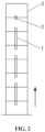
- the number of the modules 3 is eight, the number of the first fixing member 1 is three, each of the first fixing member 1 stretches across one module 3, and the number of the second fixing member 2 is one.
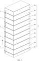
- the number of the modules 3 is ten, the number of the first fixing member 1 is four, each of the first fixing member 1 stretches across one module 3, and the number of the second fixing member 2 is one.
- the position of the second fixing member 2 may be adjusted, for example the second fixing member 2 is fixedly connected to two bottommost modules 3, which is not limited to the positions shown in FIGS. 2 and 3 .
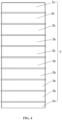
- modules 3 may be selected according to actual needs. As shown in FIG. 3 , in the vertical direction, a module 3 at the bottommost end is a base 3a, a module 3 at the topmost end is a top cover 3c, and modules 3 between the base 3a and the top cover 3c are functional modules 3b.
- the modules 3 may have other types and are not limited to the above embodiment.
- the second embodiment differs from the first embodiment mainly in the number of modules 3 across which the first fixing member 1 stretches.
- the number of the modules 3 is eight
- the first fixing member 1 is two
- the number of the second fixing member 2 is one
- each of the first fixing member 1 stretches across two modules 3.
- the number of the modules 3 across which the first fixing member 1 stretches may be three, or four or more, and is not limited to two.
- the third embodiment differs from the first embodiment mainly in that no second fixing member is provided.
- a module fixing structure of a household energy storage system includes multiple modules 3 and at least two first fixing members 1.
- the multiple modules 3 are stacked in a vertical direction, the first fixing member 1 extends along the vertical direction, and the at least two first fixing members 1 are distributed in sequence in the vertical direction.
- the first fixing member 1 stretches across at least one of the modules 3, and only two ends of the first fixing member 1 are fixed to two modules 3, respectively.
- the number of the modules 3 across which each of the at least two first fixing members 1 stretches is different. Specifically, as shown in FIG. 11 , the number of the modules 3 is eight, the number of the first fixing member 1 is three, two of the three first fixing members 1 each stretches across one module 3, and the other one of the three first fixing members 1 stretches across two modules 3.
- the number of the modules 3 across which the first fixing member 1 stretches maybe other values, which is not limited to one or two.
- the fourth embodiment differs from the first embodiment mainly in the stacking direction of the modules 3.
- a module fixing structure of a household energy storage system includes multiple modules 3, at least two first fixing members 1, and at least one second fixing member 2.
- the modules 3 are stacked both in a vertical direction and in a horizontal direction.
- the second fixing member 2 is fixedly connected to two adjacent modules 3
- at least one first fixing member 1 stretches across at least one module 3, and only two ends of the first fixing member 1 are fixedly connected to two modules 3, respectively.
- In the horizontal direction at least one first fixing member 1 stretches across at least one module 3, and only two ends of the first fixing member 1 are fixedly connected to two modules 3, respectively.
- the modules 3 stacked in the vertical direction are referred to as module columns, and the modules 3 stacked in the horizontal direction are referred to as module rows.
- the modules 3 are fixed by the first fixing member 1 in a stretching-across manner.
- the topmost two modules 3 are fixedly connected by the second fixing member 2, and the other modules 3 are fixed by the first fixing member 1 in a stretching-across manner.
- modules in other module rows 3 may be fixed by the first fixing member 1 in a stretching-across manner according to actual needs, which is not limited to the above embodiments.
- the horizontal direction may be a width direction of the modules 3, which is not limited to the direction shown in FIG. 12 ; the modules 3 may be stacked in the vertical direction and in the length direction of the modules 3, and also in the width direction of the modules 3, which is not limited to the two stacking directions shown in FIG. 12 .
- a household energy storage system is further provided.
- the household energy storage system includes the module fixing structure according to the above embodiments.
- the module fixing structure according to the above embodiments has the technical effects described above, and the household energy storage system includes the module fixing structure of a household energy storage system, the above household energy storage system also has the corresponding technical effects, which will not be repeated herein.
Landscapes
- Chemical & Material Sciences (AREA)
- Chemical Kinetics & Catalysis (AREA)
- Electrochemistry (AREA)
- General Chemical & Material Sciences (AREA)
- Engineering & Computer Science (AREA)
- Power Engineering (AREA)
- Microelectronics & Electronic Packaging (AREA)
- Battery Mounting, Suspending (AREA)
- Connector Housings Or Holding Contact Members (AREA)
- Supply And Distribution Of Alternating Current (AREA)
Abstract
Description
- The present application relates to the field of energy storage technology, and in particular to a household energy storage system and a module fixing structure thereof.
- With the development of energy storage technology in the renewable energy industry, household energy storage systems are gradually being promoted and applied. The stacked modular design is usually used in the above household energy storage systems. The modular design is implemented as dividing the entire household energy storage system into multiple modules based on functions, while the stacked modular design is implemented as sequentially stacking the multiple modules in a height direction from bottom to top.
- As the height of the stacked modules increases, the modules generally are required to be fixed in order to ensure the stability of the system. However, the conventional fixing manners are complex, which is not convenient for installation and maintenance.
- In view of the above, the technical problem to be solved by those skilled in the art is how to fix the modules to improve the convenience of installation and maintenance.
- In view of this, the object of the present application is to provide a household energy storage system and a module fixing structure thereof, to improve the convenience of installation and maintenance.
- In order to realize the above object, the following technical solutions are provided according to the present application.
- A module fixing structure of a household energy storage system includes:
- multiple modules and at least one first fixing member; where
- the multiple modules are stacked in at least one stacking direction;
- in the stacking direction in which N modules of the multiple modules are stacked, the first fixing member stretches across M modules of the multiple modules, and only two ends of the first fixing member are fixed to two of the multiple modules, respectively; where
- N is a positive integer greater than or equal to 3, and M is a positive integer less than or equal to N-2.
- In an embodiment, the number of the first fixing member is at least two; and
the at least two first fixing members stretch across a same number of modules; and/or, the at least two first fixing members stretch across different numbers of modules. - In an embodiment, the stacking direction in which the N modules are stacked is a vertical direction and/or a horizontal direction.
- In an embodiment, each of the multiple modules is of a rectangular cuboid shape, the vertical direction is a height direction of the modules, and the horizontal direction is a length direction and/or a width direction of the modules.
- In an embodiment, two adjacent modules of the multiple modules fit with each other by positioning in the stacking direction.
- In an embodiment, in the stacking direction, one of the two adjacent modules is provided with at least one positioning groove, the other of the two adjacent modules is provided with at least one positioning member, and the positioning member and the positioning groove fit with each other by positioning.
- In an embodiment, the number of the at least one positioning member is two or more, and the number of the at least one positioning groove is two or more; at least one of the two or more positioning members is a first positioning member, at least one of the two or more positioning grooves is a first positioning groove, and the first positioning member and the first positioning groove fit with each other by positioning;
- at least another one of the two or more positioning members is a second positioning member, at least another one of the two or more positioning grooves is a second positioning groove, and the second positioning member and the second positioning groove fit with each other by positioning; and
- a fit accuracy between the first positioning member and the first positioning groove is less than that between the second positioning member and the second positioning groove.
- In an embodiment, the stacking direction is a vertical direction, the first positioning member is a handle, the first positioning groove is a handle groove, the handle is arranged at a top of the other of the two adjacent modules, and the handle groove is arranged at a bottom of the one of the two adjacent modules; and
the second positioning member is a positioning rod, and the second positioning groove is a positioning rod groove. - In an embodiment, the first fixing member is fixedly connected to the modules in a detachable manner.
- In an embodiment, the module is provided with a first mounting notch, the first mounting notch and the first fixing member fit with each other by positioning and/or the first fixing member and the modules on which the first fixing member is located are flush with each other, and the first fixing member is fixed at the first mounting notch.
- In an embodiment, in a case that the first fixing member and the modules on which the first fixing member is located are flush with each other, at least one of the modules is provided with a first flange in a circumferential direction, the first flange has a first flange notch; and the first fixing member includes a first fixing plate and a first protruding portion provided on the first fixing plate;
where the first fixing plate is fixed at the first mounting notch, and the first fixing plate and the modules on which the first fixing member is located are flush with each other; the first protruding portion is arranged at the first flange notch, and the first protruding portion and the first flange are flush with each other and abutted to each other to form a closed loop structure. - In an embodiment, the module fixing structure further includes a second fixing member, where the second fixing member is used to fixedly connect two adjacent modules of the multiple modules in the stacking direction.
- In an embodiment, each of the two adjacent modules of the multiple modules is provided with a second mounting notch, the second mounting notch and the second fixing member fit with each other by positioning, and/or the second fixing member and the two adjacent modules to which the second fixing member is connected are flush with each other; and the second fixing member is fixed at the second mounting notch.
- In an embodiment, in a case that the second fixing member and the two adjacent modules to which the second fixing member is connected are flush with each other, at least one of the two adjacent modules is provided with a second flange in a circumferential direction, the second flange has a second flange notch; and the second fixing member includes a second fixing plate and a second protruding portion provided on the second fixing plate;
where the second fixing plate is fixed at the second mounting notch, and the second fixing plate and the two adjacent modules to which the second fixing plate is connected are flush with each other; the second protruding portion is arranged at the second flange notch, and the second protruding portion and the second flange at which the second protruding portion is arranged are flush with each other and abutted to each other to form a closed loop structure. - In an embodiment, at least two of the modules are functional modules and at least one of the modules is a structural module; or, at least one of the modules is a functional module and at least two of the modules are structural modules; or, each of the modules is a functional module; and
where the functional module is an energy storage module, a power control module, an inverter module, a photovoltaic power generation module or a heat dissipation module, and the structural module is a base or a top cover. - On the basis of the above module fixing structure, a household energy storage system is further provided according to the present application. The household energy storage system includes the module fixing structure according to any one of the above embodiments.
- In the module fixing structure of a household energy storage system according to the present application, the modules are stacked in at least one stacking direction, the first fixing member stretches across M modules in the stacking direction in which N modules are stacked, and only two ends of the first fixing member are fixed to two of the modules, respectively, N is a positive integer greater than or equal to 3, and M is a positive integer less than or equal to N-2. In this way, only two of the stacked N modules are required to be fixedly connected to the same first fixing member, and the M modules are not fixedly connected to the first fixing member, which reduces the number of fixed connections. Accordingly, the first fixing member stretches across the M modules in the stacking direction in which N modules are stacked, which effectively reduces the number of the first fixing member and the number of fixed connections. Therefore, with the above module fixing structure, the convenience of installation and maintenance is improved.
- For more clearly illustrating the technical solutions in the embodiments of the present application or in the conventional technology, the accompanying drawings used in the description of the embodiments or the conventional technology will be briefly described hereinafter. Apparently, the accompanying drawings described hereafter illustrate only embodiments of the present application, and other drawings can be obtained by those skilled in the art based on the provided drawings without any creative efforts.
-
FIG. 1 is a schematic view showing the structure of a module fixing structure in the conventional technology; -
FIG. 2 is a schematic view showing the structure of a module fixing structure of a household energy storage system according to a first embodiment of the present application; -
FIG. 3 is schematic view showing another structure of the module fixing structure of the household energy storage system according to the first embodiment of the present application; -
FIG. 4 is a front view of the structure shown inFIG. 3 ; -
FIG. 5 is a side view of the structure shown inFIG. 3 ; -
FIG. 6 is a schematic view showing the structure of a functional module inFIG. 3 ; -
FIG. 7 is a bottom view of the structure shown inFIG. 6 ; -
FIG. 8 is a schematic view showing the structure of a first fixing member inFIG. 3 ; -
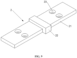
FIG. 9 is a schematic view showing the structure of a second fixing member inFIG. 3 ; -
FIG. 10 is a schematic view showing the structure of a module fixing structure of a household energy storage system according to a second embodiment of the present application; -
FIG. 11 is a schematic view showing the structure of a module fixing structure of a household energy storage system according to a third embodiment of the present application; and -
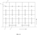
FIG. 12 is a schematic view showing the structure of a module fixing structure of a household energy storage system according to a fourth embodiment of the present application. -
01 fixing member; 02 module; 1 first fixing member; 2 second fixing member; 3 module; 4 first positioning member; 5 second positioning member; 6 first positioning groove; 7 second positioning groove; 11 first fixing plate; 12 first protruding portion; 13 first fixing hole; 111 fixing portion; 112 stretching-across portion; 21 second fixing plate; 22 second protruding portion; 23 second fixing hole; 3a base; 3b functional module; 3c top cover; 31 first mounting notch; 32 first mounting boss; 33 first flange; 34 first flange notch. - The technical solutions in the embodiments of the present application are clearly and completely described below in conjunction with the accompanying drawings. Apparently, the described embodiments are only a part of the embodiments of the present application, not all of them. Based on the embodiments in the present application, other embodiments obtained by those skilled in the art without creative efforts fall within the protection scope of the present application.
- As shown in
FIG. 1 , in the conventional household energy storage system, eightmodules 02 are stacked in sequence in a vertical direction, where the vertical direction is shown by the arrow inFIG. 1 . - Two
adjacent modules 02 are fixedly connected through a fixingmember 01. Specifically, one of the twoadjacent modules 02 is fixedly connected to one end of the fixingmember 01 and the other of the twoadjacent modules 02 is fixedly connected to the other end of the fixingmember 01. - In the above fixing structure, seven fixing
members 01 are required, i.e. seven fixing connections are performed, which does not facilitate installation and maintenance. - In addition, the household energy storage system is usually installed by a third party or by the customer, and the above fixing structure increases the complexity of on-site installation and on-site maintenance.
- In order to facilitate installation and maintenance, a module fixing structure of a household energy storage system is provided according to embodiments of the present application.
- Specifically, as shown in
FIGS. 2 ,3 ,5 and10 to 12 , the module fixing structure according to the present embodiment includesmultiple modules 3 and at least onefirst fixing member 1. Themodules 3 are stacked in at least one stacking direction; the first fixingmember 1 stretches acrossM modules 3 of themodules 3 in a stacking direction in whichN modules 3 are stacked, and only two ends of the first fixingmember 1 are fixed to two of themultiple modules 3, respectively. N is a positive integer greater than or equal to 3, and M is a positive integer less than or equal to N-2. - It should be noted that multiple or a plurality of refers to three or more. In the stacking direction in which the
N modules 3 are stacked, one end of the first fixingmember 1 is fixed to onemodule 3 of the N modules, and the other end of the first fixingmember 1 is fixed to anothermodule 3 of the N modules; and the M modules are located between the two ends of the first fixingmember 1. - As shown in
FIG. 8 , the first fixingmember 1 includes two fixingportions 111 and a stretching-acrossportion 112 located between the two fixingportions 111. Onefixing portion 111 is fixedly connected to one end of the stretching-acrossportion 112, and the other fixingportion 111 is fixedly connected to the other end of the stretching-acrossportion 112, and the fixingportion 111 is fixedly connected to thecorresponding module 3. - The
first fixing member 1 may be a one-piece structure or a split structure, depending on the actual needs. - In the above module fixing structure of a household energy storage system, only two
modules 3 of the stackedN modules 3 are required to be fixedly connected to the same first fixingmember 1, and theM modules 3 are not fixedly connected to the first fixingmember 1, which reduces the number of fixed connections. Accordingly, the first fixingmember 1 stretches across theM modules 3 in the stacking direction in whichN modules 3 are stacked, which effectively reduces the number of the first fixingmember 1 and the number of fixed connections. Therefore, with the above module fixing structure, the convenience of installation and maintenance is improved. - It will be understood that the greater the number of
modules 3 across which the first fixingmember 1 stretches, the greater the number of fixed connections is reduced by. - In the above module fixing structure, the number of the first fixing
member 1 may be one, or two or more. In a case that the number of the first fixingmember 1 is at least two, the at least twofirst fixing members 1 may stretch across the same number ofmodules 3, and/or, the at least twofirst fixing members 1 may stretch across different numbers ofmodules 3. - In the above embodiments, the number of
modules 3 across which each of first fixingmembers 1 stretches is selected according to actual needs, so that the form of fixing can be varied according to the actual situation without changing the number of fixing connections, which improves flexibility and further improves the convenience of installation and maintenance, thereby improving adaptability to complex installation environments. - The above stacking direction may be one, or two or more, depending on the actual needs. The specific direction of the above stacking direction is also selected according to actual needs. Specifically, the stacking direction is a vertical direction and/or a horizontal direction. It is understood that the horizontal direction is perpendicular to the vertical direction.
- Accordingly, the stacking direction in which
N modules 3 are stacked is a vertical direction and/or a horizontal direction. - The
above modules 3 are usually of a rectangular cuboid shape, the above vertical direction is a height direction of themodules 3, and the above horizontal direction is a length direction and/or a width direction of themodules 3. - Specifically, the stacking direction in which
N modules 3 are stacked is the height direction of themodules 3, and/or the length direction of themodules 3, and/or the width direction of themodules 3. - The arrow lines shown in
FIGS. 2 ,3 ,10 and 11 indicate the vertical direction, the solid arrow line inFIG. 6 indicates the length direction of themodules 3, the dashed arrow line inFIG. 6 indicates the width direction of themodules 3, the horizontal arrow line inFIG. 12 indicates the horizontal direction, and the vertical arrow line inFIG. 12 indicates the vertical direction. - To facilitate stacking and fixing, two
adjacent modules 3 fit with each other by positioning in the stacking direction. The specific structure of the fitting and positioning of the twomodules 3 is selected according to actual needs. Specifically, in the stacking direction, one of the twoadjacent modules 3 is provided with at least one positioning groove, the other of the twoadjacent modules 3 is provided with at least one positioning member, and the positioning member and the positioning groove fit with each other by positioning. - The specific structure and the specific number of the above positioning member and the positioning groove may be selected according to actual needs, which are not limited in the embodiment.
- As shown in
FIG. 6 and7 , in order to improve the positioning effect, two or more positioning members and two or more positioning grooves are provided; where at least one of the positioning members is a first positioning member 4, at least one of the positioning grooves is afirst positioning groove 6, and the first positioning member 4 and thefirst positioning groove 6 fit with each other by positioning; at least another one of the positioning members is asecond positioning member 5, at least another one of the positioning grooves is asecond positioning groove 7, and thesecond positioning member 5 and thesecond positioning groove 7 fit with each other by positioning. A fit accuracy between the first positioning member 4 and thefirst positioning groove 6 is less than that between thesecond positioning member 5 and thesecond positioning groove 7. - In the above structure, coarse positioning (i.e., primary positioning) is realized by the first positioning member 4 and the
first positioning groove 6, and fine positioning (i.e., secondary positioning) is realized by thesecond positioning member 5 and thesecond positioning groove 7. In this way, when the first fixingmember 1 is used for fixing in a stretching-across manner, the installation difficulties between themodules 3 due to manufacturing and installation errors can be effectively reduced. - Generally, the
modules 3 each is provided with a handle. If the stacking direction is the vertical direction, as shown inFIGS. 6 and7 , the first positioning member 4 is embodied as the handle and thefirst positioning groove 6 may be a handle groove, where the handle is located at a top of themodule 3 having the handle and the handle groove is located at a bottom of themodule 3 having the handle groove. In this way, coarse positioning can be realized by the handle and the handle groove, which makes full use of the handle structure of themodule 3 itself, and thereby the structure is simplified. - In actual application, alternatively, coarse positioning can be realized by means of other positioning structures, which are not limited to the above embodiments.
- In order to facilitate improving the fit accuracy, the
second positioning member 5 may be a positioning rod and thesecond positioning groove 7 may be a positioning rod groove. - In actual application, other positioning structures, such as mortise and tenon joint, may also be used to improve the fit accuracy, which are not limited to the above embodiments.
- The specific number and distribution of the first positioning member 4 and the
second positioning member 5 are determined according to actual needs. As shown inFIG. 6 , for example, the first positioning member 4 is a handle, themodule 3 is of a rectangular cuboid shape, and the number of the handle on themodule 3 is two and the two handles are distributed in sequence in the length direction of themodule 3, and the length direction of the handles parallel to the width direction of themodule 3. For example, thesecond positioning member 5 is a positioning rod, themodule 3 is of a rectangular cuboid shape, and the number of the positioning rod is at least two and the at least two positioning rods are distributed in sequence in the length direction, width direction or diagonal direction of themodule 3. - To facilitate maintenance of the
module 3, the first fixingmember 1 may be fixedly connected to themodule 3 in a detachable manner. Optionally, the first fixingmember 1 and themodule 3 are fixedly connected through a threaded connecting member, so that the structure is simple and the fixing is reliable. - Specifically, the first fixing
member 1 andmodule 3 are fixedly connected through screws. As shown inFIG. 8 , the first fixingmember 1 is provided with first fixing holes 13 for the screws to pass through, and each of the first fixing holes 13 is a countersunk hole. In this way, the screws can be hidden and the appearance is improved. - In actual application, the structure for fixing the first fixing
member 1 and themodule 3 is not limited to the above way, and the first fixingmember 1 may be fixed to themodules 3 by using one of manners or a combination of at least two of the manners of a binding member, a snap-on structure and a clamping member. - The specific structures of the first fixing
member 1 and themodules 3 may be selected according to actual needs. As shown inFIGS. 6 and7 , theabove module 3 is provided with a first mountingnotch 31, and the first fixingmember 1 is fixed at the first mountingnotch 31. - In an aspect, the first mounting
notch 31 and the first fixingmember 1 may fit with each other by positioning. In this way, the positioning effect of the first mountingnotch 31 on the first fixingmember 1 during installation prevents the first fixing member from being deflected during the fixation, thus facilitating fixing the first fixing member and also improving the fixing efficiency. - In another aspect, the first fixing
member 1 may be flush with themodules 3 at which the first fixingmember 1 is located, so that the first fixingmember 1 does not protrude from themodules 3 after the entire first fixingmember 1 is mounted at themodules 3, which effectively improves the appearance and reduces the size of the entire structure. - The above two aspects may be combined or not, depending on actual needs, which are not limited in the embodiment.
- In the above structure, if the first fixing
member 1 is flush with themodules 3 on which the first fixingmember 1 is located and at least onemodule 3 is provided with afirst flange 33 in a circumferential direction, thefirst flange 33 may have afirst flange notch 34. As shown inFIG. 8 , the first fixingmember 1 includes afirst fixing plate 11 and a first protrudingportion 12 provided on thefirst fixing plate 11. Thefirst fixing plate 11 is fixed at the first mountingnotch 31 and thefirst fixing plate 11 is flush with themodules 3 at which thefirst fixing plate 11 is located. The first protrudingportion 12 is located at thefirst flange notch 34, and the first protrudingportion 12 and thefirst flange 33 at which the first protrudingportion 12 is located are flush with each other and abutted to each other to form a closed loop structure. - It should be noted that if the first mounting
notch 31 and the first fixingmember 1 fit with each other by positioning, the first mountingnotch 31 and thefirst fixing plate 11 fit with each other by positioning. - The number of the first protruding
portion 12 in the first fixingmember 1 is related to the number ofmodules 3 across which the first fixingmember 1 stretches, which is not limited in this embodiment. - To facilitate fixing, the
module 3 may be provided with a first mountingboss 32 at the first mountingnotch 31. The first mountingboss 32 is provided with a mounting hole for fixing the first fixingmember 1. - Generally, the
module 3 is of a rectangular cuboid shape, the first fixingmember 1 may be arranged on an edge of themodule 3, as shown inFIGS. 3 to 5 . Alternatively, the first fixingmember 1 may be arranged between two edges of themodule 3. - In the above module fixing structure of a household energy storage system, if after the
modules 3 is fixed by using the first fixingmember 1, only onemodule 3 remains unfixed in the stacking direction, and the only onemodule 3 remained in the stacking direction may be fixed by using asecond fixing member 2. Specifically, the second fixingmember 2 is fixedly connected to twoadjacent modules 3 in the stacking direction. Therefore, based on the above situations, the module fixing structure further includes asecond fixing member 2 which is fixedly connected to twoadjacent modules 3 in the stacking direction. - To facilitate maintenance of the
modules 3, the second fixingmember 2 may be fixedly connected to themodules 3 in a detachable manner. Optionally, the second fixingmember 2 and themodules 3 are fixedly connected through a threaded connecting member, so that the structure is simple and the fixing is reliable. - Specifically, the second fixing
member 2 and themodule 3 are fixedly connected through screws. As shown inFIG. 9 , the second fixingmember 2 is provided with second fixing holes 23 for the screws to pass through, and each of the second fixing holes 23 is a countersunk hole. In this way, the screws can be hidden and the appearance is improved. - In actual application, the structure for fixing the second fixing
member 2 to themodules 3 is not limited to the above manners, and the second fixingmember 2 may be fixed to themodules 3 by using one of manners or a combination of at least two of the manners of a binding member, a snap-on structure and a clamping member. - The specific structures of the second fixing
member 2 and themodules 3 described above are selected according to actual needs. To facilitate fixing, themodule 3 is provided with a second mounting notch, and the second fixingmember 2 is fixed at the second mounting notch. - In an aspect, the second mounting notch and the second fixing
member 2 may fit with each other by positioning. In this way, the positioning effect of the second mounting notch on the second fixingmember 2 during installation prevents the second fixingmember 2 from being deflected during the fixation, thus facilitating fixing the second fixingmember 2 and also improving the fixing efficiency. - In another aspect, the second fixing
member 2 may be flush with themodules 3 at which the second fixingmember 2 is located, so that the second fixingmember 2 does not protrude from themodules 3 after the entire second fixingmember 2 is mounted at themodules 3, which effectively improves the appearance and reduces the size of the entire structure. - The above two aspects may be combined or not, depending on actual needs, which are not limited in the embodiment.
- In the above structure, if the second fixing
member 1 is flush with the modules 3at which the second fixingmember 1 is located and at least onemodule 3 is provided with a second flange in a circumferential direction, the second flange may have a second flange notch. As shown inFIG. 9 , the second fixingmember 2 includes asecond fixing plate 21 and a second protrudingportion 22 provided on thesecond fixing plate 21. Thesecond fixing plate 21 is fixed at the second mounting notch, and thesecond fixing plate 21 is flush with themodules 3 at which thesecond fixing plate 21 is located. The second protrudingportion 22 is located at the second flange notch, and the second protrudingportion 22 and the second flange at which the second protrudingportion 22 is located are flush with each other and abutted to each other to form a closed loop structure. - It should be noted that the second mounting notch, the second flange and the second flange notch are not shown in the attached drawings. The second mounting notch may be referred to the first mounting
notch 31, the second flange may be referred to thefirst flange 33, and the second flange notch may be referred to thefirst flange notch 34. If the second mounting notch and the second fixingmember 2 fit with each other by positioning, the second mounting notch and the second fixingmember 21 fit with each other by positioning. - In the second fixing
member 2, the second protrudingportion 22 is located in a middle of the second fixingmember 2, and the second fixing holes 23 are located at two ends of the second fixingmember 2. - Generally, the
module 3 is of a rectangular cuboid shape, the second fixingmember 2 may be arranged on an edge of themodule 3 or between two edges of themodule 3. - In the module fixing structure according to the above embodiment, the
module 3 refers to a functional module that can be included in the household energy storage system or a structural module that can be stacked in the household energy storage system. The functional module may be an energy storage module, a power control module, an inverter module, or a heat dissipation module, and the above structural module may be a base or a top cover, or the like. If the household energy storage system is a light storage and charging system, alternatively, the functional module may be a photovoltaic power generation module. - In an aspect, at least one
module 3 may be a functional module and at least twomodules 3 may be structural modules, or at least twomodules 3 may be functional modules and at least onemodule 3 may be a structural module. - In another aspect, each of the
modules 3 may be a functional module. - In actual application, if there are more structural modules, e.g. three or more structural modules are provided, each of the
modules 3 may be a structural module. - It should be noted that in a case that at least two
modules 3 are functional modules, the at least two functional modules may be the same or different; and in a case that at least twomodules 3 are structural modules, the at least two structural modules may be the same or different. - In order to more specifically illustrate the technical solutions according to the present application, four embodiments are illustrated hereinafter.
- As shown in
FIGS. 2 and3 , a module fixing structure of a household energy storage system according to a first embodiment includesmultiple modules 3, at least onefirst fixing member 1, and at least onesecond fixing member 2. - The
multiple modules 3 are stacked in a vertical direction. Thesecond fixing member 2 is fixedly connected to twotopmost modules 3, and the remainingmodules 3 are fixedly connected by the first fixingmember 1. - Specifically, the first fixing
member 1 extends along a vertical direction, the first fixingmember 1 stretches across at least onemodule 3, and only two ends of the first fixingmember 1 are fixed to the other twomodules 3, respectively. - As shown in
FIG. 2 , the number of themodules 3 is eight, the number of the first fixingmember 1 is three, each of the first fixingmember 1 stretches across onemodule 3, and the number of the second fixingmember 2 is one. As shown inFIG. 3 , the number of themodules 3 is ten, the number of the first fixingmember 1 is four, each of the first fixingmember 1 stretches across onemodule 3, and the number of the second fixingmember 2 is one. - In the first embodiment, the position of the second fixing
member 2 may be adjusted, for example the second fixingmember 2 is fixedly connected to twobottommost modules 3, which is not limited to the positions shown inFIGS. 2 and3 . - The specific types of the
modules 3 may be selected according to actual needs. As shown inFIG. 3 , in the vertical direction, amodule 3 at the bottommost end is abase 3a, amodule 3 at the topmost end is atop cover 3c, andmodules 3 between thebase 3a and thetop cover 3c arefunctional modules 3b. - In practical applications, the
modules 3 may have other types and are not limited to the above embodiment. - As shown in
FIG. 10 , the second embodiment differs from the first embodiment mainly in the number ofmodules 3 across which the first fixingmember 1 stretches. Specifically, in the second embodiment, the number of themodules 3 is eight, the first fixingmember 1 is two, the number of the second fixingmember 2 is one, and each of the first fixingmember 1 stretches across twomodules 3. - In actual application, the number of the
modules 3 across which the first fixingmember 1 stretches may be three, or four or more, and is not limited to two. - As shown in
FIG. 11 , the third embodiment differs from the first embodiment mainly in that no second fixing member is provided. - Specifically, a module fixing structure of a household energy storage system according to the third embodiment includes
multiple modules 3 and at least twofirst fixing members 1. - The
multiple modules 3 are stacked in a vertical direction, the first fixingmember 1 extends along the vertical direction, and the at least twofirst fixing members 1 are distributed in sequence in the vertical direction. - The
first fixing member 1 stretches across at least one of themodules 3, and only two ends of the first fixingmember 1 are fixed to twomodules 3, respectively. - In the third embodiment, the number of the
modules 3 across which each of the at least twofirst fixing members 1 stretches is different. Specifically, as shown inFIG. 11 , the number of themodules 3 is eight, the number of the first fixingmember 1 is three, two of the threefirst fixing members 1 each stretches across onemodule 3, and the other one of the threefirst fixing members 1 stretches across twomodules 3. - In the third embodiment, the number of the
modules 3 across which the first fixingmember 1 stretches maybe other values, which is not limited to one or two. - As shown in
FIG. 12 , the fourth embodiment differs from the first embodiment mainly in the stacking direction of themodules 3. - A module fixing structure of a household energy storage system according to the fourth embodiment includes
multiple modules 3, at least twofirst fixing members 1, and at least onesecond fixing member 2. - The
modules 3 are stacked both in a vertical direction and in a horizontal direction. In the vertical direction, the second fixingmember 2 is fixedly connected to twoadjacent modules 3, at least onefirst fixing member 1 stretches across at least onemodule 3, and only two ends of the first fixingmember 1 are fixedly connected to twomodules 3, respectively. In the horizontal direction, at least onefirst fixing member 1 stretches across at least onemodule 3, and only two ends of the first fixingmember 1 are fixedly connected to twomodules 3, respectively. - Specifically, the
modules 3 stacked in the vertical direction are referred to as module columns, and themodules 3 stacked in the horizontal direction are referred to as module rows. In the vertical direction, in a module row located in the bottom rows, themodules 3 are fixed by the first fixingmember 1 in a stretching-across manner. In each of the module columns, the topmost twomodules 3 are fixedly connected by the second fixingmember 2, and theother modules 3 are fixed by the first fixingmember 1 in a stretching-across manner. - Of course, modules in
other module rows 3 may be fixed by the first fixingmember 1 in a stretching-across manner according to actual needs, which is not limited to the above embodiments. - In actual application, the horizontal direction may be a width direction of the
modules 3, which is not limited to the direction shown inFIG. 12 ; themodules 3 may be stacked in the vertical direction and in the length direction of themodules 3, and also in the width direction of themodules 3, which is not limited to the two stacking directions shown inFIG. 12 . - Based on the module fixing structure according to the above embodiments, a household energy storage system is further provided. The household energy storage system includes the module fixing structure according to the above embodiments.
- Since the module fixing structure according to the above embodiments has the technical effects described above, and the household energy storage system includes the module fixing structure of a household energy storage system, the above household energy storage system also has the corresponding technical effects, which will not be repeated herein.
- The above description of the disclosed embodiments enables those skilled in the art to implement or use the present application. Various modifications to the embodiments are apparent to those skilled in the art, and general principles defined herein can be implemented in other embodiments without departing from the scope of the present application. Therefore, the present application is not limited to the embodiments described herein, and conforms to the widest scope consistent with the principles and novel features disclosed herein.
Claims (16)
- A module fixing structure applicable to a household energy storage system, comprising:a plurality of modules (3) and at least one first fixing member (1); whereinthe plurality of modules (3) are stacked in at least one stacking direction;in a stacking direction of the at least one stacking direction in which N modules (3) of the plurality of modules (3) are stacked, the first fixing member (1) stretches across M modules (3) of the plurality of modules (3), and only two ends of the first fixing member (1) are fixed to two of the plurality of modules (3), respectively; whereinN is a positive integer greater than or equal to 3, and M is a positive integer less than or equal to N-2.
- The module fixing structure according to claim 1, whereinthe number of the first fixing member (1) is at least two; andthe at least two first fixing members (1) stretch across a same number of modules (3); and/or, the at least two first fixing members (1) stretch across different numbers of modules (3).
- The module fixing structure according to claim 1, wherein the stacking direction in which the N modules (3) are stacked is a vertical direction and/or a horizontal direction.
- The module fixing structure according to claim 3, wherein each of the plurality of modules (3) is of a rectangular cuboid shape, the vertical direction is a height direction of the modules (3), and the horizontal direction is a length direction and/or a width direction of the modules (3).
- The module fixing structure according to claim 1, wherein two adjacent modules (3) of the plurality of modules (3) fit with each other by positioning in the stacking direction.
- The module fixing structure according to claim 5, wherein in the stacking direction, one of the two adjacent modules (3) is provided with at least one positioning groove, the other of the two adjacent modules (3) is provided with at least one positioning member, and the positioning member and the positioning groove fit with each other by positioning.
- The module fixing structure according to claim 6, whereinthe number of the at least one positioning member is two or more, and the number of the at least one positioning groove is two or more; whereinat least one of the two or more positioning members is a first positioning member (4), at least one of the two or more positioning grooves is a first positioning groove (6), and the first positioning member (4) and the first positioning groove (6) fit with each other by positioning; andat least another one of the two or more positioning members is a second positioning member (5), at least another one of the two or more positioning grooves is a second positioning groove (7), and the second positioning member (5) and the second positioning groove (7) fit with each other by positioning; and whereina fit accuracy between the first positioning member (4) and the first positioning groove (6) is less than that between the second positioning member (5) and the second positioning groove (7).
- The module fixing structure according to claim 7, whereinthe stacking direction is a vertical direction, the first positioning member (4) is a handle, the first positioning groove (6) is a handle groove, the handle is arranged at a top of the other of the two adjacent modules (3), and the handle groove is arranged at a bottom of the one of the two adjacent modules (3); andthe second positioning member (5) is a positioning rod, and the second positioning groove (7) is a positioning rod groove.
- The module fixing structure according to claim 1, wherein the first fixing member (1) is fixedly connected to the modules (3) in a detachable manner.
- The module fixing structure according to claim 1, wherein the module (3) is provided with a first mounting notch (31), the first mounting notch (31) and the first fixing member (1) fit with each other by positioning and/or the first fixing member (1) and the modules (3) at which the first fixing member (1) is located are flush with each other; and the first fixing member (1) is fixed at the first mounting notch (31).
- The module fixing structure according to claim 10, whereinin a case that the first fixing member (1) and the modules (3) at which the first fixing member (1) is located are flush with each other, at least one of the modules (3) is provided with a first flange (33) in a circumferential direction, the first flange (33) has a first flange notch (34); and the first fixing member (1) comprises a first fixing plate (11) and a first protruding portion (12) provided on the first fixing plate (11); whereinthe first fixing plate (11) is fixed at the first mounting notch (31), and the first fixing plate (11) and the modules (3) at which the first fixing member (1) is located are flush with each other; the first protruding portion (12) is arranged at the first flange notch (34), and the first protruding portion (12) and the first flange (33) are flush with each other and abutted to each other to form a closed loop structure.
- The module fixing structure according to claim 1, further comprising a second fixing member (2), wherein the second fixing member (2) is configured to fixedly connect two adjacent modules (3) of the plurality of modules (3) in the stacking direction.
- The module fixing structure according to claim 12, wherein each of the two adjacent modules (3) of the plurality of the modules (3) is provided with a second mounting notch, the second mounting notch and the second fixing member (2) fit with each other by positioning, and/or the second fixing member (2) and the two adjacent modules (3) to which the second fixing member (2) is connected are flush with each other; and the second fixing member (2) is fixed at the second mounting notch.
- The module fixing structure according to claim 13, whereinin a case that the second fixing member (2) and the two adjacent modules (3) to which the second fixing member (2) is connected are flush with each other, at least one of the two adjacent modules (3) is provided with a second flange in a circumferential direction, the second flange has a second flange notch; and the second fixing member (2) comprises a second fixing plate and a second protruding portion provided on the second fixing plate;wherein the second fixing plate is fixed at the second mounting notch, and the second fixing plate and the two adjacent modules (3) to which the second fixing plate is connected are flush with each other; the second protruding portion is arranged at the second flange notch, and the second protruding portion and the second flange at which the second protruding portion is arranged are flush with each other and abutted to each other to form a closed loop structure.
- The module fixing structure according to any one of claims 1 to 14, whereinat least two of the modules (3) are functional modules and at least one of the modules (3) is a structural module; or, at least one of the modules (3) is a functional module and at least two of the modules (3) are structural modules; or, each of the modules (3) is a functional module; and whereinthe functional module is an energy storage module, a power control module, an inverter module, a photovoltaic power generation module or a heat dissipation module, and the structural module is a base or a top cover.
- A household energy storage system, comprising the module fixing structure according to any one of claims 1 to 15.
Applications Claiming Priority (1)
| Application Number | Priority Date | Filing Date | Title |
|---|---|---|---|
| CN202222241717.8U CN218783743U (en) | 2022-08-24 | 2022-08-24 | Household energy storage system and its module fixed structure |
Publications (3)
| Publication Number | Publication Date |
|---|---|
| EP4333176A1 true EP4333176A1 (en) | 2024-03-06 |
| EP4333176C0 EP4333176C0 (en) | 2025-02-12 |
| EP4333176B1 EP4333176B1 (en) | 2025-02-12 |
Family
ID=85707030
Family Applications (1)
| Application Number | Title | Priority Date | Filing Date |
|---|---|---|---|
| EP23185109.8A Active EP4333176B1 (en) | 2022-08-24 | 2023-07-12 | Household energy storage system and module fixing structure thereof |
Country Status (5)
| Country | Link |
|---|---|
| US (1) | US20240072361A1 (en) |
| EP (1) | EP4333176B1 (en) |
| CN (1) | CN218783743U (en) |
| AU (1) | AU2023204407B2 (en) |
| ZA (1) | ZA202307286B (en) |
Families Citing this family (2)
| Publication number | Priority date | Publication date | Assignee | Title |
|---|---|---|---|---|
| CN118448798A (en) * | 2024-05-27 | 2024-08-06 | 厦门新能达科技有限公司 | Battery module, energy storage device and installation method of energy storage device |
| CN223436605U (en) * | 2024-09-29 | 2025-10-14 | 惠州亿纬锂能股份有限公司 | Battery box and battery pack |
Citations (2)
| Publication number | Priority date | Publication date | Assignee | Title |
|---|---|---|---|---|
| CN215644823U (en) * | 2021-07-28 | 2022-01-25 | 天合光能股份有限公司 | Energy storage unit and energy storage battery using the same |
| EP3958372A1 (en) * | 2020-08-21 | 2022-02-23 | Sungrow Power Supply Co., Ltd. | Energy storage cabinet |
-
2022
- 2022-08-24 CN CN202222241717.8U patent/CN218783743U/en active Active
-
2023
- 2023-07-07 AU AU2023204407A patent/AU2023204407B2/en active Active
- 2023-07-10 US US18/349,810 patent/US20240072361A1/en active Pending
- 2023-07-12 EP EP23185109.8A patent/EP4333176B1/en active Active
- 2023-07-21 ZA ZA2023/07286A patent/ZA202307286B/en unknown
Patent Citations (2)
| Publication number | Priority date | Publication date | Assignee | Title |
|---|---|---|---|---|
| EP3958372A1 (en) * | 2020-08-21 | 2022-02-23 | Sungrow Power Supply Co., Ltd. | Energy storage cabinet |
| CN215644823U (en) * | 2021-07-28 | 2022-01-25 | 天合光能股份有限公司 | Energy storage unit and energy storage battery using the same |
Also Published As
| Publication number | Publication date |
|---|---|
| AU2023204407A1 (en) | 2024-03-14 |
| AU2023204407B2 (en) | 2025-01-23 |
| EP4333176C0 (en) | 2025-02-12 |
| CN218783743U (en) | 2023-03-31 |
| EP4333176B1 (en) | 2025-02-12 |
| US20240072361A1 (en) | 2024-02-29 |
| ZA202307286B (en) | 2024-03-27 |
Similar Documents
| Publication | Publication Date | Title |
|---|---|---|
| EP4333176A1 (en) | Household energy storage system and module fixing structure thereof | |
| US9154074B2 (en) | Apparatus for forming and mounting a photovoltaic array | |
| US9243817B2 (en) | Apparatus for forming and mounting a photovoltaic array | |
| KR101953446B1 (en) | Solar panel mechanical connector and frame | |
| US20050058891A1 (en) | Front access battery tray apparatus and system | |
| US20100043862A1 (en) | Solar Panel Interconnection System | |
| CN109769410B (en) | Photovoltaic module with electrical connector port towards corner | |
| EP3621420B1 (en) | Photovoltaic inverter | |
| US10812013B2 (en) | Frame assemblies and photovoltaic devices including the same | |
| US20240332711A1 (en) | Stacked power supply modules | |
| US20120031472A1 (en) | Support for Photovoltaic Module and Photovoltaic Module | |
| US20250286508A1 (en) | Solar panel assembly method | |
| CN218448314U (en) | Household energy storage system | |
| WO2024198317A1 (en) | Adjustable floating body, floating system and floating photovoltaic power station | |
| KR20220018683A (en) | Bifacial solar module frame and bifacial solar system | |
| CN210123948U (en) | A kind of interface unit | |
| EP4597712A1 (en) | Battery module, energy storage device and energy storage system | |
| CN219180679U (en) | Energy storage system | |
| CN206921873U (en) | A kind of battery modules | |
| CN217469866U (en) | Photovoltaic module frame convenient to it is fixed | |
| CN216948725U (en) | Novel antidetonation hinge base | |
| CN221057882U (en) | Assembled low-voltage cabinet body | |
| CN220106744U (en) | Battery module | |
| CN222979979U (en) | Mainframe box and central control mainframe | |
| CN217427930U (en) | Mounting structure of piece together piece formula linear electric motor iron core |
Legal Events
| Date | Code | Title | Description |
|---|---|---|---|
| PUAI | Public reference made under article 153(3) epc to a published international application that has entered the european phase |
Free format text: ORIGINAL CODE: 0009012 |
|
| STAA | Information on the status of an ep patent application or granted ep patent |
Free format text: STATUS: REQUEST FOR EXAMINATION WAS MADE |
|
| 17P | Request for examination filed |
Effective date: 20230712 |
|
| AK | Designated contracting states |
Kind code of ref document: A1 Designated state(s): AL AT BE BG CH CY CZ DE DK EE ES FI FR GB GR HR HU IE IS IT LI LT LU LV MC ME MK MT NL NO PL PT RO RS SE SI SK SM TR |
|
| GRAP | Despatch of communication of intention to grant a patent |
Free format text: ORIGINAL CODE: EPIDOSNIGR1 |
|
| STAA | Information on the status of an ep patent application or granted ep patent |
Free format text: STATUS: GRANT OF PATENT IS INTENDED |
|
| INTG | Intention to grant announced |
Effective date: 20240919 |
|
| GRAS | Grant fee paid |
Free format text: ORIGINAL CODE: EPIDOSNIGR3 |
|
| GRAA | (expected) grant |
Free format text: ORIGINAL CODE: 0009210 |
|
| STAA | Information on the status of an ep patent application or granted ep patent |
Free format text: STATUS: THE PATENT HAS BEEN GRANTED |
|
| AK | Designated contracting states |
Kind code of ref document: B1 Designated state(s): AL AT BE BG CH CY CZ DE DK EE ES FI FR GB GR HR HU IE IS IT LI LT LU LV MC ME MK MT NL NO PL PT RO RS SE SI SK SM TR |
|
| REG | Reference to a national code |
Ref country code: GB Ref legal event code: FG4D |
|
| REG | Reference to a national code |
Ref country code: CH Ref legal event code: EP |
|
| REG | Reference to a national code |
Ref country code: DE Ref legal event code: R096 Ref document number: 602023001991 Country of ref document: DE |
|
| REG | Reference to a national code |
Ref country code: IE Ref legal event code: FG4D |
|
| U01 | Request for unitary effect filed |
Effective date: 20250303 |
|
| U07 | Unitary effect registered |
Designated state(s): AT BE BG DE DK EE FI FR IT LT LU LV MT NL PT RO SE SI Effective date: 20250310 |
|
| PG25 | Lapsed in a contracting state [announced via postgrant information from national office to epo] |
Ref country code: RS Free format text: LAPSE BECAUSE OF FAILURE TO SUBMIT A TRANSLATION OF THE DESCRIPTION OR TO PAY THE FEE WITHIN THE PRESCRIBED TIME-LIMIT Effective date: 20250512 |
|
| PG25 | Lapsed in a contracting state [announced via postgrant information from national office to epo] |
Ref country code: PL Free format text: LAPSE BECAUSE OF FAILURE TO SUBMIT A TRANSLATION OF THE DESCRIPTION OR TO PAY THE FEE WITHIN THE PRESCRIBED TIME-LIMIT Effective date: 20250212 |
|
| PG25 | Lapsed in a contracting state [announced via postgrant information from national office to epo] |
Ref country code: ES Free format text: LAPSE BECAUSE OF FAILURE TO SUBMIT A TRANSLATION OF THE DESCRIPTION OR TO PAY THE FEE WITHIN THE PRESCRIBED TIME-LIMIT Effective date: 20250212 |
|
| PG25 | Lapsed in a contracting state [announced via postgrant information from national office to epo] |
Ref country code: IS Free format text: LAPSE BECAUSE OF FAILURE TO SUBMIT A TRANSLATION OF THE DESCRIPTION OR TO PAY THE FEE WITHIN THE PRESCRIBED TIME-LIMIT Effective date: 20250612 Ref country code: NO Free format text: LAPSE BECAUSE OF FAILURE TO SUBMIT A TRANSLATION OF THE DESCRIPTION OR TO PAY THE FEE WITHIN THE PRESCRIBED TIME-LIMIT Effective date: 20250512 |
|
| PG25 | Lapsed in a contracting state [announced via postgrant information from national office to epo] |
Ref country code: HR Free format text: LAPSE BECAUSE OF FAILURE TO SUBMIT A TRANSLATION OF THE DESCRIPTION OR TO PAY THE FEE WITHIN THE PRESCRIBED TIME-LIMIT Effective date: 20250212 |
|
| PG25 | Lapsed in a contracting state [announced via postgrant information from national office to epo] |
Ref country code: GR Free format text: LAPSE BECAUSE OF FAILURE TO SUBMIT A TRANSLATION OF THE DESCRIPTION OR TO PAY THE FEE WITHIN THE PRESCRIBED TIME-LIMIT Effective date: 20250513 |
|
| U20 | Renewal fee for the european patent with unitary effect paid |
Year of fee payment: 3 Effective date: 20250725 |
|
| PG25 | Lapsed in a contracting state [announced via postgrant information from national office to epo] |
Ref country code: SM Free format text: LAPSE BECAUSE OF FAILURE TO SUBMIT A TRANSLATION OF THE DESCRIPTION OR TO PAY THE FEE WITHIN THE PRESCRIBED TIME-LIMIT Effective date: 20250212 |
|
| PG25 | Lapsed in a contracting state [announced via postgrant information from national office to epo] |
Ref country code: CZ Free format text: LAPSE BECAUSE OF FAILURE TO SUBMIT A TRANSLATION OF THE DESCRIPTION OR TO PAY THE FEE WITHIN THE PRESCRIBED TIME-LIMIT Effective date: 20250212 |
|
| PG25 | Lapsed in a contracting state [announced via postgrant information from national office to epo] |
Ref country code: SK Free format text: LAPSE BECAUSE OF FAILURE TO SUBMIT A TRANSLATION OF THE DESCRIPTION OR TO PAY THE FEE WITHIN THE PRESCRIBED TIME-LIMIT Effective date: 20250212 |
|
| PLBE | No opposition filed within time limit |
Free format text: ORIGINAL CODE: 0009261 |
|
| STAA | Information on the status of an ep patent application or granted ep patent |
Free format text: STATUS: NO OPPOSITION FILED WITHIN TIME LIMIT |
|
| 26N | No opposition filed |
Effective date: 20251113 |