EP4333137A1 - Battery - Google Patents
Battery Download PDFInfo
- Publication number
- EP4333137A1 EP4333137A1 EP21954532.4A EP21954532A EP4333137A1 EP 4333137 A1 EP4333137 A1 EP 4333137A1 EP 21954532 A EP21954532 A EP 21954532A EP 4333137 A1 EP4333137 A1 EP 4333137A1
- Authority
- EP
- European Patent Office
- Prior art keywords
- connection portion
- pin
- connection
- sheet
- adapter
- Prior art date
- Legal status (The legal status is an assumption and is not a legal conclusion. Google has not performed a legal analysis and makes no representation as to the accuracy of the status listed.)
- Pending
Links
Images



Classifications
-
- H—ELECTRICITY
- H01—ELECTRIC ELEMENTS
- H01M—PROCESSES OR MEANS, e.g. BATTERIES, FOR THE DIRECT CONVERSION OF CHEMICAL ENERGY INTO ELECTRICAL ENERGY
- H01M50/00—Constructional details or processes of manufacture of the non-active parts of electrochemical cells other than fuel cells, e.g. hybrid cells
- H01M50/50—Current conducting connections for cells or batteries
- H01M50/531—Electrode connections inside a battery casing
-
- H—ELECTRICITY
- H01—ELECTRIC ELEMENTS
- H01M—PROCESSES OR MEANS, e.g. BATTERIES, FOR THE DIRECT CONVERSION OF CHEMICAL ENERGY INTO ELECTRICAL ENERGY
- H01M50/00—Constructional details or processes of manufacture of the non-active parts of electrochemical cells other than fuel cells, e.g. hybrid cells
- H01M50/50—Current conducting connections for cells or batteries
- H01M50/543—Terminals
- H01M50/564—Terminals characterised by their manufacturing process
- H01M50/566—Terminals characterised by their manufacturing process by welding, soldering or brazing
-
- H—ELECTRICITY
- H01—ELECTRIC ELEMENTS
- H01M—PROCESSES OR MEANS, e.g. BATTERIES, FOR THE DIRECT CONVERSION OF CHEMICAL ENERGY INTO ELECTRICAL ENERGY
- H01M50/00—Constructional details or processes of manufacture of the non-active parts of electrochemical cells other than fuel cells, e.g. hybrid cells
- H01M50/10—Primary casings; Jackets or wrappings
- H01M50/102—Primary casings; Jackets or wrappings characterised by their shape or physical structure
- H01M50/109—Primary casings; Jackets or wrappings characterised by their shape or physical structure of button or coin shape
-
- H—ELECTRICITY
- H01—ELECTRIC ELEMENTS
- H01M—PROCESSES OR MEANS, e.g. BATTERIES, FOR THE DIRECT CONVERSION OF CHEMICAL ENERGY INTO ELECTRICAL ENERGY
- H01M10/00—Secondary cells; Manufacture thereof
- H01M10/04—Construction or manufacture in general
-
- H—ELECTRICITY
- H01—ELECTRIC ELEMENTS
- H01M—PROCESSES OR MEANS, e.g. BATTERIES, FOR THE DIRECT CONVERSION OF CHEMICAL ENERGY INTO ELECTRICAL ENERGY
- H01M10/00—Secondary cells; Manufacture thereof
- H01M10/04—Construction or manufacture in general
- H01M10/0422—Cells or battery with cylindrical casing
- H01M10/0427—Button cells
-
- H—ELECTRICITY
- H01—ELECTRIC ELEMENTS
- H01M—PROCESSES OR MEANS, e.g. BATTERIES, FOR THE DIRECT CONVERSION OF CHEMICAL ENERGY INTO ELECTRICAL ENERGY
- H01M50/00—Constructional details or processes of manufacture of the non-active parts of electrochemical cells other than fuel cells, e.g. hybrid cells
- H01M50/10—Primary casings; Jackets or wrappings
- H01M50/147—Lids or covers
- H01M50/148—Lids or covers characterised by their shape
- H01M50/153—Lids or covers characterised by their shape for button or coin cells
-
- H—ELECTRICITY
- H01—ELECTRIC ELEMENTS
- H01M—PROCESSES OR MEANS, e.g. BATTERIES, FOR THE DIRECT CONVERSION OF CHEMICAL ENERGY INTO ELECTRICAL ENERGY
- H01M50/00—Constructional details or processes of manufacture of the non-active parts of electrochemical cells other than fuel cells, e.g. hybrid cells
- H01M50/10—Primary casings; Jackets or wrappings
- H01M50/172—Arrangements of electric connectors penetrating the casing
- H01M50/174—Arrangements of electric connectors penetrating the casing adapted for the shape of the cells
- H01M50/181—Arrangements of electric connectors penetrating the casing adapted for the shape of the cells for button or coin cells
-
- H—ELECTRICITY
- H01—ELECTRIC ELEMENTS
- H01M—PROCESSES OR MEANS, e.g. BATTERIES, FOR THE DIRECT CONVERSION OF CHEMICAL ENERGY INTO ELECTRICAL ENERGY
- H01M50/00—Constructional details or processes of manufacture of the non-active parts of electrochemical cells other than fuel cells, e.g. hybrid cells
- H01M50/50—Current conducting connections for cells or batteries
- H01M50/531—Electrode connections inside a battery casing
- H01M50/536—Electrode connections inside a battery casing characterised by the method of fixing the leads to the electrodes, e.g. by welding
-
- H—ELECTRICITY
- H01—ELECTRIC ELEMENTS
- H01M—PROCESSES OR MEANS, e.g. BATTERIES, FOR THE DIRECT CONVERSION OF CHEMICAL ENERGY INTO ELECTRICAL ENERGY
- H01M50/00—Constructional details or processes of manufacture of the non-active parts of electrochemical cells other than fuel cells, e.g. hybrid cells
- H01M50/50—Current conducting connections for cells or batteries
- H01M50/543—Terminals
- H01M50/552—Terminals characterised by their shape
- H01M50/559—Terminals adapted for cells having curved cross-section, e.g. round, elliptic or button cells
-
- H—ELECTRICITY
- H01—ELECTRIC ELEMENTS
- H01M—PROCESSES OR MEANS, e.g. BATTERIES, FOR THE DIRECT CONVERSION OF CHEMICAL ENERGY INTO ELECTRICAL ENERGY
- H01M50/00—Constructional details or processes of manufacture of the non-active parts of electrochemical cells other than fuel cells, e.g. hybrid cells
- H01M50/60—Arrangements or processes for filling or topping-up with liquids; Arrangements or processes for draining liquids from casings
- H01M50/609—Arrangements or processes for filling with liquid, e.g. electrolytes
- H01M50/627—Filling ports
- H01M50/636—Closing or sealing filling ports, e.g. using lids
-
- Y—GENERAL TAGGING OF NEW TECHNOLOGICAL DEVELOPMENTS; GENERAL TAGGING OF CROSS-SECTIONAL TECHNOLOGIES SPANNING OVER SEVERAL SECTIONS OF THE IPC; TECHNICAL SUBJECTS COVERED BY FORMER USPC CROSS-REFERENCE ART COLLECTIONS [XRACs] AND DIGESTS
- Y02—TECHNOLOGIES OR APPLICATIONS FOR MITIGATION OR ADAPTATION AGAINST CLIMATE CHANGE
- Y02E—REDUCTION OF GREENHOUSE GAS [GHG] EMISSIONS, RELATED TO ENERGY GENERATION, TRANSMISSION OR DISTRIBUTION
- Y02E60/00—Enabling technologies; Technologies with a potential or indirect contribution to GHG emissions mitigation
- Y02E60/10—Energy storage using batteries
Definitions
- the present application relates to a battery, belonging to the field of batteries.
- Batteries are a common electrochemical energy storage device widely used in electronic products and other fields.
- button batteries are often used in wearable electronic products.
- Battery pack generally refers to the packaging, encapsulation, and assembly of a battery, which is an indispensable part of the battery and an important factor affecting its stability and other performance.
- a battery has a battery cell and a pack structure for packaging the battery cell.
- the battery cell includes a stacked positive electrode sheet, a separator, a negative electrode sheet, a positive electrode tab connected to the positive electrode sheet, and a negative electrode tab connected to the negative electrode sheet, the pack structure is provided with a positive adapter (positive PIN) and a negative adapter (negative PIN).
- the positive PIN is electrically connected to the positive electrode tab
- the negative PIN is electrically connected to the negative electrode tab, thereby achieving that the positive PIN and negative PIN serve as wires for connecting the internal circuit of the battery to peripheral circuit.
- the current battery pack structure is not conducive to, for example, the stability of the battery.
- the common positive PIN and negative PIN are wires connected with the positive electrode tab and the negative electrode tab, respectively, and thus there are such defects that, for example, the positive PIN and the negative PIN in the battery pack structure cannot be firmly set, which affect the stability and other performance of the battery.
- the present application provides a battery with good stability and other performance, which can effectively overcome the shortcomings in existing technology.
- the present application provides a battery including a shell, a top cover, a battery cell, and a second adapter part, where the top cover seals an upper end of the shell and forms a cavity together with the shell, the battery cell is located within the cavity, the shell includes a side wall surrounding the cavity and a bottom shell arranged at a lower end of the side wall, the battery cell has a first tab and a second tab, and the first tab and the second tab have opposite polarities, where the bottom shell is electrically connected to the second tab, and the second adapter part includes a second connection sheet and a second pin, the second adapter part is connected to the bottom shell through the second connection sheet; one end of the second pin is connected to the second connection sheet, and the other end of the second pin extends out of an outer edge of the bottom shell.
- the second connection sheet includes a third connection portion, a fourth connection portion, and a transition portion connected between the third connection portion and the fourth connection portion, where the third connection portion is welded to the bottom shell, a top surface of the fourth connection portion is higher than that of the third connection portion, and/or a bottom surface of the fourth connection portion is higher than that of the third connection portion.
- the bottom shell is further provided with a second insulation layer
- the second connection sheet includes a third connection portion, a fourth connection portion, and a transition portion connected between the third connection portion and the fourth connection portion
- the third connection portion is welded to the bottom shell
- the fourth connection portion is connected to the bottom shell through the second insulation layer.
- the top cover includes a first metal sheet, a first insulation sheet and a second metal sheet, where the first metal sheet is connected to the upper end of the shell to achieve the top cover sealing the upper end of the shell, the second metal sheet is insulatively connected to the first metal sheet through the first insulation sheet; the top cover is provided with a through hole that runs through the first metal sheet and the second metal sheet, the through hole is communicated with the cavity, the second metal sheet includes a first connection portion and a second connection portion connected to the first connection portion, the first connection portion is connected to the first insulation sheet, and the second connection portion is provided at the through hole and seals the through hole; the battery further includes a first adapter part, the first adapter part includes a first connection sheet and a first pin, one end of the first pin is connected to the first connection sheet, and the other end of the first pin extends out of an outer edge of the top cover; the second connection portion is electrically connected to the first tab, and the first adapter part is connected to the second connection portion through
- an outer peripheral edge of the first metal sheet is welded to an upper end of the side wall to achieve the top cover sealing the upper end of the shell.
- the first connection sheet is welded to the second connection portion, and a first welded mark generated by the welding runs through the first connection sheet and extends to 1/3 to 2/3 of thickness of the second connection portion.
- the first adapter part is located on a side of the second metal sheet away from the cavity.
- the second connection portion is provided with a liquid injection hole communicated with the cavity and a sealing piece for sealing the liquid injection hole, the sealing piece is located on a side of the second connection portion away from the cavity, and the sealing piece is electrically connected to the first tab through the second connection portion, and the first connection sheet is welded to the sealing piece.
- the first welded mark generated by the welding runs through the first connection sheet and extends to 1/3 to 2/3 of thickness of the sealing piece.
- a surface of the sealing piece away from the cavity is no higher than a surface of the first connection portion away from the cavity.
- the side wall of the shell is provided with a first insulation layer, and at least one of the following features is met: a part where the other end of the first pin extends out of the outer edge of the top cover is the first adapter, the first pin further includes a first extension portion extending to the side wall of the shell, one end of the first extension portion is connected to the first connection sheet, and the other end of the first extension portion is connected to the first adapter, the first extension portion is insulated from the side wall through the first insulation layer; a part where the other end of the second pin extending out of the outer edge of the bottom shell is the second adapter, the second pin further includes a second extension portion extending to the side wall of the shell, one end of the second extension portion is connected to the second connection sheet, and the other end of the second extension portion is connected to the second adapter, the second extension portion is connected to the side wall of the shell through the first insulation layer.
- the second pin includes a positioning pin and a conductive pin, and in a direction from the bottom shell to the top cover, a distance from the second adapter of the positioning pin to the top cover is greater than or equal to a distance from the second adapter of the conductive pin to the top cover, and/or, the distance from the second adapter of the positioning pin to the top cover is greater than or equal to a distance from the first adapter of the first pin to the top cover.
- the second pin includes a positioning pin and a conductive pin, and in a projection of the battery perpendicular to a direction from the bottom shell to the top cover, the positioning pin is located between the conductive pin and the first pin.
- the second connection sheet includes a third connection portion, a fourth connection portion, and a transition portion connected between the third connection portion and the fourth connection portion; where the third connection portion is welded to the bottom shell; a top surface of the fourth connection portion is higher than a top surface of the third connection portion, and/or a bottom surface of the fourth connection portion is higher than a bottom surface of the third connection portion; a part where the other end of the first pin extending out of the outer edge of the top cover is the first adapter, and a part where the other end of the second pin extends out of the outer edge of the bottom shell is the second adapter; the second pin includes a conductive pin and a positioning pin, in a projection of the shell perpendicular to a direction from the bottom shell to the top cover, the second adapter of the positioning pin is located between the first adapter of the first pin and the second adapter of the conductive pin, and an included angle between a first connection line and a second connection line is ⁇ , with ⁇ > 30
- the second pin is arranged on the fourth connection portion.
- a second welded mark generated by welding runs through the third connection portion and extends to 1/3 to 2/3 of thickness of the bottom shell.
- the second insulation layer has a thickness of 0.05mm-0. 1mm.
- a cross section of the second connection sheet perpendicular to a thickness direction of the second connection sheet is an incomplete semi-circular ring with an opening.
- an outer edge of the second connection sheet is in a shape of arc, and the arc is basically concentric with the outer edge of the shell.
- the second adapter part is located on a side of the bottom shell away from the cavity.
- a second insulation sheet arranged at a side of the top cover away from the cavity is further included, and an orthographic projection of the second insulation sheet in a direction perpendicular to a thickness of the top cover covers an orthographic projection of the top cover in a direction perpendicular to the thickness of the top cover.
- the first tab is a positive electrode tab
- the second tab is a negative electrode tab
- the battery is a button battery.
- the second adapter is arranged on a bottom shell of the battery pack structure through a second connection sheet, and electrically connected to the second tab through the shell, the second pin of the second adapter part extends out of an outer edge of the bottom shell, can serve as a connector connecting with a peripheral circuit and also play a positioning role, which is conducive to improving a stability of the battery after it is assembled in an electronic product and can ensure the stability of an electrical connection between the second adapter part and the second tab, so as to avoid an occurrence of such as breakage of the first adapter part and second adapter part from the battery pack structure, thereby ensuring the stability and other performance of the battery and ensuring functional performance of the battery.
- first”, “second”, “third”, and “fourth” are only used for descriptive purposes, such as distinguishing between components to better illustrate/explain the technical solutions, and cannot be understood as indicating or implying the quantity or substantive order of the indicated technical features.
- Terms such as “above” and “below” for indicating the orientation are used to express the relative position relationships of the components, with a side where the top cover is located as the top, a side where the bottom shell is located as the bottom, and an outer surface of a wall of the cavity between the top cover and the bottom shell as the side surface.
- a battery of the present application includes a shell 1, a top cover 2, a battery cell, and a second adapter part 4.
- the top cover 2 seals an upper end of a side wall and forms a cavity 6 together with the shell 1.
- the battery cell 9 is located inside the cavity 6, and the shell 1 includes a side wall surrounding the cavity 6 and a bottom shell 15 arranged at a lower end of the side wall.
- the battery cell 9 has a first tab and a second tab, and the polarity of the first tab is opposite to that of the second tab.
- the bottom shell is electrically connected to the second tab
- the second adapter part 4 includes a second connection sheet and a second pin
- the second adapter part 4 is connected to the bottom shell through the second connection sheet; one end of the second pin is connected to the second connection sheet, and the other end of the second pin extends out of an outer edge of the bottom shell.
- the above-mentioned battery further includes a first adapter part 3, which includes a first connection sheet 34 and a first pin arranged on the first connection sheet 34.
- the first adapter part 3 is arranged on the top cover through the first connection sheet 34, one end of the first pin is connected to the first connection sheet 34, and the other end of the first pin extends out of the outer edge of the top cover.
- the above top cover can be specifically formed by heat pressing and laminating two layers of metal sheets and an insulation sheet, where the insulation sheet is located between the two layers of metal sheets.
- the top cover includes a first metal sheet 21, a first insulation sheet 23, and a second metal sheet 22.
- the first metal sheet 21 is connected to an upper end of the shell 1 to achieve the top cover sealing the upper end of the shell 1, and the second metal sheet 22 is insulatively connected to the first metal sheet 21 through the first insulation sheet 23; the top cover is provided with a through hole that runs through the first metal sheet 21 and the second metal sheet 22, the through hole is communicated with the cavity 6.
- the second metal sheet 22 includes a first connection portion 221 and a second connection portion 222 connected to the first connection portion 221.
- the first connection portion 221 is connected to the first insulation sheet 23, and the second connection portion 222 is located at the through hole and seals the through hole;
- the first adapter part 3 includes a first connection sheet 34 and a first pin arranged on the first connection sheet 34. One end of the first pin is connected to the first connection sheet 34, and the other end of the first pin extends out of the outer edge of the top cover;
- the second connection portion 222 is electrically connected to the first tab, and the first adapter part 3 is connected to the second connection portion 222 through the first connection sheet 34, thereby electrically connecting the first adapter part 3 to the first tab.
- the first adapter part 3 is electrically connected to the first tab and insulated from the second tab
- the second adapter part 4 is electrically connected to the second tab and insulated from the first tab
- the first adapter part 3 can be located on a side of the second metal sheet 22 away from the cavity 6
- the second adapter part 4 can be located on a side of the bottom shell away from the cavity 6.
- the first metal sheet 21, the first insulation sheet 23, and the second metal sheet 22 are sequentially arranged in layers, so that the first metal sheet 21 and the second metal sheet 22 are insulatively connected through the first insulation sheet 23.
- the through hole runs through the first metal sheet 21 and the first insulation sheet 22, that is, the through hole includes a first through hole that runs through the first metal sheet 21 and a second through hole that runs through the first insulation sheet 23.
- the first through hole and the second through hole are communicated with the cavity 6 and are basically concentric with the cavity 6.
- a diameter of the first through hole is slightly larger than that of the second through hole, and a side of the first insulation sheet 23 close to the second through hole extends downwards to forms a protrusion located inside the first through hole, the protrusion is located between the first metal sheet 21 and the second connection portion 222 of the second metal sheet 22, so that the first metal sheet 21 and the second connection portion 222 are insulated through the first insulation sheet 23.
- the first connection portion 221 is connected to the first metal sheet 21 through the first insulation sheet 23, that is, the first connection portion 221 is also insulated from the first metal sheet 21 through the first insulation sheet 23, thereby isolating the first metal sheet 21 from the second metal sheet 22 through the first insulation sheet 23.
- the outer peripheral edge of the top cover can be welded to the upper end of the side wall to achieve the top cover sealing the upper end of the side wall.
- an outer peripheral edge of the first metal sheet 21 is welded to the upper end of the side wall to achieve the top cover sealing the upper end of the side wall.
- the shell 1 and the bottom shell 15 can be integrally formed, or the outer peripheral edge of the bottom shell 15 can be welded to a lower end of the shell 1. There is no specific limitation on this in the present application.
- the first connection sheet 34 can be welded to the second connection portion 222, and a first welded mark generated by the welding runs through the first connection sheet 34 and extends to 1/3 to 2/3 of thickness of the second connection portion 222, which is conducive to further improving the sealing, stability and other performance of the battery.
- a laser welding method can be used for welding. In a welding process, the first connection sheet 34 is laminated with the second connection portion 222, and then laser is projected onto the first connection sheet 34 for welding.
- a welding strength is controlled by adjusting laser welding parameters, so that the generated welded mark runs through the first connection sheet 34 and extends to 1/3 to 2/3 of thickness of the second connection portion 222, that is, a length of the welded mark generated in the second connection portion 222 in the thickness direction of the second connection portion 222 is about 1/3 to 2/3 of thickness of the second connection portion 222 (i.e., a depth of fusion of the second connection portion 222 caused by the welding is about 1/3 to 2/3 of the thickness of the second connection portion 222).
- the second connection portion 222 may also be provided with a liquid injection hole communicated with the cavity 6, and a sealing piece 5 for sealing the liquid injection hole.
- the sealing piece 5 is located on a side of the second connection portion 222 away from the cavity 6, and the sealing piece 5 is electrically connected to the first tab through the second connection portion 222.
- the first connection sheet 34 is welded to the sealing piece 5, a first welded mark generated by the welding runs through the first connection sheet 34 and extends to 1/3 to 2/3 of thickness of the sealing piece 5 (i.e., a depth of fusion of the sealing piece 5 caused by the welding is about 1/3 to 2/3 of the thickness of the sealing piece 5), and the liquid injection hole can be used for injection of an electrolyte, for example.
- the first tab is welded to the second connection portion 222, and the sealing piece 5 is welded to the second connection portion 222.
- the second metal sheet 22 further includes a first connection portion 221 connected to the second connection portion 222, and a surface of the sealing piece 5 away from the cavity 6 is no higher than a surface of the first connection portion 221 away from the cavity 6.
- the second metal sheet 22 is provided with a groove located above the second connection portion 222, and the groove is formed by surrounding of the first connection portion 221 (i.e., a side wall of the groove is the first connection portion 221, and a bottom of the groove is the second connection portion 222), and the sealing piece 5 is located within the groove, and a depth of the groove is such that a surface of the sealing piece 5 away from the cavity 6 is no higher than a surface of the first connection portion 221 away from the cavity 6, and preferably, the surface of the sealing piece 5 away from the cavity 6 is lower than the surface of the first connection portion 221 away from the cavity 6 (i.e., the surface of the sealing piece 5 away from the cavity 6 is located below the surface of the first connection portion 221 away from the cavity 6, thereby rendering
- the sealing piece 5 is located in the groove, and specifically, it can be welded to the second connection portion 222 at a lower part of the groove.
- a cross section of the sealing piece 5 and a cross section of the groove perpendicular to a thickness direction of the sealing piece 5 are circular, the sealing piece 5 is concentric with the groove, and an outer diameter of the sealing piece 5 is smaller than an inner diameter of the groove and in this way, there is a gap between the sealing piece 5 and the sidewall of the groove.
- the first metal sheet 21, the first insulation sheet 23, and the first connection portion 221 of the second metal sheet are sequentially laminated, where the second metal sheet 22 can specifically be connected to the first insulation sheet 23 through the first connection portion 221.
- the second connection portion 222 is located at the through hole, and generally runs through the through hole.
- a surface of the second connection portion 222 facing the cavity 6 is connected to the first tab, and a surface thereof facing away the cavity 6 is connected to the first connection sheet 34.
- the surface of the second connection portion 222 facing the cavity 6 is basically flush with a surface of the first metal sheet 21 facing the cavity 6 or located below the surface of the first metal sheet 21 facing the cavity 6 (i.e., being closer to the cavity 6 than the surface of the first metal sheet 21 facing the cavity 6), which facilitates a connection between the first tab and the second connection portion 222.
- the first tab may include a straight portion 8 connected to the battery cell 9.
- a surface of the straight portion 8 perpendicular to a thickness direction of the straight portion 8 is basically parallel to a surface of the second connection portion 222 perpendicular to a thickness direction of the second connection portion 222.
- the straight portion 8 is welded to the second connection portion 222 to achieve a connection between the second connection portion 222 and the first tab.
- a third insulation layer 13 can be arranged on the surface of the first metal sheet 21 facing the cavity 6, and the third insulation layer 13 is located between the first metal sheet 21 and the straight portion 8 of the first tab, so that the first tab is insulated from the first metal sheet 21 through the third insulation layer 13.
- the first connection sheet 34, the sealing piece 5, the second metal sheet 22, the first insulation sheet 23, the second metal sheet 22, the liquid injection hole, the through hole, and the cavity 6 are basically concentric.
- Shapes of a cross section of the first connection sheet 34 perpendicular to its thickness direction and a cross section of the sealing piece 5 perpendicular to its thickness direction can be, for example, circular;
- shapes of a cross section of the second metal sheet 22 perpendicular to its thickness direction, a cross section of the first insulation sheet 23 perpendicular to its thickness direction and a cross section of the second metal sheet 22 perpendicular to its thickness direction can be, for example, circular;
- the battery for example, is a button battery, but it is not limited thereto.
- the above thickness direction is the same as a direction from the bottom shell 15 to the top cover 2 (i.e., an axial direction of the battery).
- the first adapter part 3 and the second adapter part 4 serve as wires for connecting the battery to a peripheral circuit.
- a part of the first adapter part 3 extending out of the outer edge of the top cover and a part of the second adapter part 4 extending out of the outer edge of the bottom shell serve as adapters (i.e., the first adapter and the second adapter described below) for connecting to the peripheral circuit, so that the battery is connected by the adapters to the peripheral circuit, for example, a circuit in an electronic product equipped with the battery.
- the first pin can be in a straight shape, that is, the first pin can be a flat structure extending outward from the first connection sheet 34. A surface of the flat structure perpendicular to its thickness direction is parallel to a surface of the first connection sheet 34 perpendicular to its thickness direction.
- the first pin can also be in other shape such as an L-shape.
- a first insulation layer 11 is provided on a side wall of the shell, and a part where the other end of the first pin extending out of the outer edge of the top cover is the first adapter 31, the first pin further includes a first extension portion 32 extending to the side wall of the shell; one end of the first extension portion 32 is connected to the first connection sheet 34, and the other end thereof is connected to the first adapter 31, the first extension portion 32 is insulated from the side wall through the first insulation layer 11.
- Such structure facilitates an assembly of the battery into an electronic product through the first adapter 31, and it not only achieves a circuit communication between the battery and the electronic product, but also facilitates positioning of the battery in the electronic product through the first adapter 31, improving a stability of the battery in the electronic product.
- an orthographic projection of the second metal sheet 22 perpendicular to an axial direction of the battery covers an orthographic projection of the first connection sheet 34 perpendicular to the axial direction of the battery, that is, the first connection sheet 34 does not exceed beyond an outer edge of the second metal sheet 22.
- a cross section of the second metal sheet 22 perpendicular to its thickness direction is circular
- a cross section of the first connection sheet 34 perpendicular to its thickness direction is circular
- the second metal sheet 22 is concentric with the first connection sheet 34
- an outer diameter of the second metal sheet 22 is greater than an outer diameter of the first connection sheet 34.
- the first pin bends at a junction between the top cover and the side wall of the shell, extends to the side wall of the shell through the first extension portion 32, so that the first adapter 31 is located on a side surface of the shell (the surface of the side wall away from the cavity 6).
- the first pin can include a horizontal portion 33, a first bending portion and the first extension portion 32; the first connection sheet 34, the horizontal portion 33, the first bending portion and the first extension portion 32 are sequentially connected.
- the first pin is bent at a junction between the top cover and the side wall through the first bending portion, so that the first extension portion 32 is located on the side wall of the shell 1, that is, the horizontal portion 33 is located on the top cover, and its surface is basically parallel to the surface of the first connection sheet 34.
- first bending portion is connected to the horizontal portion 33, and the other end thereof is connected to one end of the first extension portion 32, and the other end of the first extension portion 32 is connected to the first adapter 31 (as shown in FIGs. 4 and 5 ).
- first bending portion and the first extension portion 32 are insulated from the side wall of the shell through the first insulation layer 11, so that the first adapter part 3 is insulated from the second tab, avoiding a short circuit and other phenomenon.
- the first adapter 31 can be in a form of sheet, and an included angle between a plane where a surface of the first adapter 31 perpendicular to the thickness direction of the first adapter 31 is located and an axial direction of the battery is less than or equal to 90 °, preferably around 90 °, that is, the surface of the first adapter 31 perpendicular to its thickness direction is basically perpendicular to the axial direction of the battery.
- the first adapter part can be integrally formed, and for example, it can be integrally formed by the first connection sheet, the horizontal portion, the first extension portion and the first adapter.
- the first insulation layer 11 surrounds the side wall of the shell, which is equivalent to that the side wall of the shell is located in a cavity formed by the first insulation layer 11.
- the first metal sheet 21, the first insulation sheet 23, the second metal sheet 22, the sealing piece 5 and the first connection sheet 34 are concentrically arranged.
- An outer diameter of the first metal sheet 21, an outer diameter of the first insulation sheet 23, an outer diameter of the second metal sheet 22, a diameter of the sealing piece 5 and a diameter of the first connection sheet 34 are sequentially reduced.
- a fourth insulation layer 14 is further provided in an area not covered by the first insulation sheet 23 in a surface of the second metal sheet 22 away from the cavity 6.
- a side of the fourth insulation layer 14 is connected to the first insulation sheet 23, and the other side thereof is connected to the first insulation layer 11 of the side wall.
- the fourth insulation layer 14 is located between the horizontal portion 33 of the first pin and the first metal sheet 21, so that the first pin is insulated from the first metal sheet 21 through the fourth insulation layer 14 to avoid short circuit and other phenomenon.
- the second pin can be in a straight shape, that is, the second pin is a flat structure extending outward from the second connection sheet.
- a surface of the flat structure perpendicular to its thickness direction is basically parallel to a surface of the second connection sheet perpendicular to its thickness direction.
- the second pin can also be in other shape such as an L-shape.
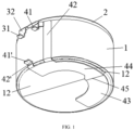
- a part of the other end of the second pin extending out of the outer edge of the bottom shell is the second adapter (such as the second adapter 41 and the second adapter 41' in FIGs.
- the second pin further includes a second extension portion extending to the side wall of the shell 1 (such as the second extension portion 42 of the conductive pin and the second extension portion 42' of the positioning pin in FIG. 1 ), the second connection sheet is connected to one end of the second extension portion, and the second adapter is connected to the other end of the second extension portion, and the second extension portion is connected to the side wall of the shell through the first insulation layer 11 (i.e., the first insulation layer 11 is located between the second extension portion and the side wall).
- a second extension portion extending to the side wall of the shell 1 (such as the second extension portion 42 of the conductive pin and the second extension portion 42' of the positioning pin in FIG. 1 ), the second connection sheet is connected to one end of the second extension portion, and the second adapter is connected to the other end of the second extension portion, and the second extension portion is connected to the side wall of the shell through the first insulation layer 11 (i.e., the first insulation layer 11 is located between the second extension portion and the side wall).
- This structure facilitates the assembly of the battery into the electronic product through the second adapter, and it not only achieves circuit communication between the battery and the electronic product, but also facilitates the positioning of the battery in the electronic product through the second adapter, improving the stability of the battery in the electronic product.
- an orthographic projection of the bottom shell 15 perpendicular to the axial direction of the battery covers an orthographic projection of the second connection sheet perpendicular to the axial direction of the battery, that is, the second connection sheet does not exceed beyond the outer edge of the bottom shell.
- a cross section of the bottom shell perpendicular to its thickness direction is circular
- a cross section of the second connection sheet perpendicular to its thickness direction is semi-circular
- the bottom shell is concentric with the second connection sheet
- an outer diameter of the bottom shell is not less than an outer diameter of the second connection sheet, and generally larger than the outer diameter of the second connection sheet
- the second pin bends at a junction between the bottom shell and the side wall and extends to the side wall of the shell through the second extension portion, so that the second adapter is located on a side surface of the shell.
- the second pin includes the second bending portion and the second extension portion.
- the second connection sheet, the second bending portion and the second extension portion are sequentially connected, and the second pin bends at a junction between the bottom shell and the side wall through the second bending portion so that the second extension portion is located on the side wall of the shell, that is, one end of the first bending portion is connected to the second connection sheet located on the bottom shell, and other end thereof is connected to one end of the second extension portion located on the side wall of the shell, and the other end of the second extension portion is connected to the second adapter, and the second bending portion and the second extension portion are connected to the side wall of the shell through the first insulation layer 11.
- the second adapter can be in the form of sheet, and an included angle between a plane where a surface of the second adapter perpendicular to the thickness direction of the second adapter is located and the axial direction of the battery is less than or equal to 90 °, preferably around 90 °, that is, the surface of the second adapter part perpendicular to its thickness direction is basically perpendicular to the axial direction of the battery.
- the second adapter can be integrally formed, and for example, it can be integrally formed by the second connection sheet, the second bending portion, the second extension portion and the first adapter.
- a conductive pin and a positioning pin are set on the second adapter part, where the conductive pin and positioning pin are integrally formed, to further simplify the battery structure and to improve the structural stability and other performance of the battery.
- the second pin includes a positioning pin and a conductive pin.
- the positioning pin can be located between the conductive pin and the first pin.
- a distance from the second adapter 41' of the positioning pin to the top cover is greater than or equal to a distance from the second adapter 41 of the conductive pin to the top cover, and/or a distance from the second adapter 41' of the positioning pin to the top cover is greater than or equal to a distance from the first adapter 41 of the first pin to the top cover, that is, the second adapter 41' of the positioning pin can be no higher than the second adapter 41 of the conductive pin and/or the first adapter 31 of the first pin.
- a distance from the second adapter 41' of the positioning pin to the bottom shell 15 is less than or equal to a distance from the second adapter 41 of the conductive pin to the bottom shell 15 and/or a distance from the first adapter 31 of the first pin to the bottom shell.
- the second adapter 41' of the positioning pin is preferably lower than the second adapter 41' of the conductive pin and/or the first adapter 31 of the first pin (i.e., the second adapter 41' of the positioning pin is located below the second adapter 41 and/or the first adapter 31 of the first pin, and the second adapter 41 of the conductive pin and/or the first adapter 31 of the first pin is closer to the top cover than the second adapter 41' of the positioning pin); for example, the second adapter 41' of the positioning pin can be located below the second adapter 41 of the conductive pin, or below the first adapter 31 of the first pin, or below both the first adapter 31 of the first pin and the second adapter 41 of the conductive pin (as shown in FIG.
- distances from the second adapter 41 of the conductive pin and the first adapter 31 of the first pin to the top cover can be basically equal or unequal, that is, heights of both of them on the side wall of the shell can be the same or different, and the present application does not have any particular restrictions on this.
- the distance is a vertical distance from the first adapter or the second adapter to the top cover.
- the second adapter part 4 can be specifically welded to the bottom shell 15 and electrically connected to the second tab through the bottom shell 15.
- the second connection sheet includes a third connection portion 43, a fourth connection portion 44, and a transition portion connected between the third connection portion 43 and the fourth connection portion 44, where the third connection portion 43 is welded to the bottom shell 15; a top surface of the fourth connection portion 44 (a surface facing the bottom shell) is higher than a top surface of the third connection portion 43 (a surface facing the bottom shell) and/or a bottom surface of the fourth connection portion (a surface facing away the bottom shell) is higher than a bottom surface of the third connection portion (a surface facing away the bottom shell).
- the top surface of the fourth connection portion 44 is farther away from the bottom shell 15 than the top surface of the third connection portion 43 and/or the bottom surface of the fourth connection portion 44 is farther away from the bottom shell 15 than the bottom surface of the third connection portion 43 to the bottom shell 15, which is equivalent to that the second connection sheet is bent through the transition portion to form the third connection portion 43 and the fourth connection portion 44, respectively.
- it can play a role of magnetic shielding, that is, a magnetic field generated by the current during operation of the battery is shielded, so that an impact of the magnetic field on the electronic product using the battery is avoided, such as the electronic product generating noise and other phenomenon caused by the magnetic field are avoided, and thus the performance of the battery is further improved.
- the bottom shell 15 is further provided with a second insulation layer
- the second connection sheet includes a third connection portion 43, a fourth connection portion 44, and a transition portion connected between the third connection portion 43 and the fourth connection portion 44, where the third connection portion 43 is welded to the bottom shell 15, and the fourth connection portion 44 is connected to the bottom shell 15 through the second insulation layer 12 (i.e., the second insulation layer 12 is located between the fourth connection portion 44 and the bottom shell 15).
- a top surface of the fourth connection portion 44 is generally higher than a top surface of the third connection portion and/or a bottom surface of the fourth connection portion is higher than a bottom surface of the third connection portion (the surface facing away the bottom shell).
- a thickness of the second insulation layer 12 can be 0.05mm-0.1mm, such as 0.05mm, 0.08mm, 0.1mm, etc.
- An orthographic projection of the second insulation layer 12 perpendicular to a thickness direction of the fourth connection portion 44 covers an orthographic projection of the fourth connection portion 44 perpendicular to a thickness direction of the fourth connection portion 44.
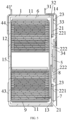
- a surface area of the second insulation layer 12 can be approximately 1/3 to 1/2 of surface area of the bottom shell, and its shape is, but not limited to, for example, a semi-circular (as shown in FIGs. 1 and 2 ).
- the third connection portion 43 is welded to the bottom shell 15, and a second welded mark generated by this welding runs through the third connection portion 43 and extends to 1/3 to 2/3 of the thickness of the bottom shell 15, which is conducive to further improving the structural stability and other performance of the battery.
- a laser welding method can be used for welding. During the welding process, the third connection portion 43 of the second connection sheet is stacked on the bottom shell 15, and then laser is projected to the third connection portion 43 for welding.
- a welding strengthen is controlled by adjusting laser welding parameters, so that the generated welded mark runs through the third connection portion 43 and extends to 1/3 to 2/3 of the thickness of the bottom shell 15, that is, a length of the welded mark generated in the bottom shell 15 in the thickness direction of the bottom shell 15 is approximately 1/3 to 2/3 of the thickness of the bottom shell 15 (i.e., a depth of fusion of the bottom shell 15 caused by this welding is approximately 1/3 to 2/3 of the thickness of the bottom shell 15).
- the second pin can be specifically set on the fourth connection portion 44, that is, one end of the second pin is connected to the fourth connection portion 44, and other end thereof serves as a connector for connecting the peripheral circuit.
- the second pin includes a conductive pin and a positioning pin, and the second adapter 41' of the positioning pin is located between the first adapter 31 of the first pin and the second adapter 41 of the conductive pin.
- the second adapter 41' of the positioning pin is located between the first adapter 31 of the first pin and the second adapter 41 of the conductive pin, and it is satisfied that an included angle between a first connection line and a second connection line is ⁇ , with ⁇ > 30 °, where the first connection line is a straight line passing through a center point of an orthogonal projection of the bottom shell 15 and bisecting the transition portion, and the second connection line is a straight line passing through the center point of the orthogonal projection of the bottom shell 15 and bisecting the second adapter 41' of the positioning pin.
- the first connection line bisects the transition portion, that is, a distance from the first connection line to a junction between the transition portion and the third connection portion 43 is basically equal to a distance from the first connection line to a junction between the transition portion and the fourth connection portion 44
- the second connection line bisects the second adapter 41' of the positioning pin, that is, a distance from the second connection line to one side (designated as a first side) of the second adapter 41' of the positioning pin is basically equal to a distance from the second connection line to the other side (designated as a second side) of the second adapter 41' of the positioning pin.
- the first side is opposite to the second side, and a center point of the orthogonal projection of the bottom shell 15 is located at a center of the orthogonal projection of the top cover.
- the orthogonal projection of the bottom shell 15 is circular, then the center point is a center of a circle of the orthogonal projection of the bottom shell 15; or the orthographic projection of the bottom shell 15 is a rectangle (or square), then the center point is an intersection of two diagonal lines of the rectangle (or square).
- ⁇ can be 40 °, 50 °, 60 °, 70 °, 80 °, 90 °, 100 °, 110 °, 120 °, 130 °, 140 °, or an angle value in a range consisting of any two of them, generally, it can be preferably 60 ° ⁇ ⁇ 140 °, more preferably 100 ° ⁇ ⁇ 125 °, for example 108 ° (as shown in FIG. 3 ).
- the conductive pin can be used as the wire between the battery and the peripheral circuit, and the second adapter thereof serves as a connector for connecting to the peripheral circuit;
- the positioning pin is used as a positioning structure for assembling the battery in the electronic product, so that the battery is snapped into the electronic product through the second adapter (or called as positioning sheet) of the positioning pin, achieving the assembly of the battery in the electronic product.
- the second adapter or called as positioning sheet
- the positioning pin, the conductive pin and the second connection sheet are integrally formed and they all have conductivity, the functions of the positioning pin and the conductive pin can also be interchanged as needed, that is, the positioning pin is used as the wire between the battery and the peripheral circuit, while the conductive pin is used as the positioning structure for assembling the battery in the electronic product.
- a cross section of the second connection sheet perpendicular to the thickness direction of the second connection sheet can be an incomplete circular ring (or arc) with an opening, that is, one end of the third connection portion 43 is connected to one end of the fourth connection portion 44 and the other end of the third connection portion 43 is not connected to the other end of the fourth connection portion 44, to form a circular opening, so that a cross section of the second connection sheet is an incomplete circular ring with an opening, for example, it is a semi-circular ring.
- the outer edge of the second connection sheet is in a shape of arc, and the arc is basically concentric with the outer edge of the shell, which facilitates the processing and positioning of the battery.
- the "basically concentric” refers to that a degree of concentricity between the two is within an error range, that is, due to existence of a processing error, it is usually not possible to achieve complete concentricity, and only being concentric as much as possible.
- the above-mentioned battery further includes a second insulation sheet 7 located on a side of the top cover away from the cavity 6.
- An orthographic projection of the second insulation sheet 7 perpendicular to the thickness direction of the top cover covers an orthographic projection of the top cover perpendicular to the thickness direction of the top cover. That is, parts that the first connection sheet 34, the horizontal portion 33 of the first pin, the second metal sheet 22, the first metal sheet 21 and the like are located on the top cover are all covered by the second insulation sheet 7, which is conducive to further improving the safety and other performance of the battery, preventing short circuit and other phenomenon when assembling the battery to a terminal product (such as a wearable electronic product) or during transportation, use and other process.
- a terminal product such as a wearable electronic product
- the above-mentioned battery cell 9 includes a positive electrode sheet, a negative electrode sheet, and a diaphragm located between the positive electrode sheet and the negative electrode sheet.
- the diaphragm is used to separate the positive electrode sheet and the negative electrode sheet, avoiding short circuit caused by a contact between the positive electrode sheet and the negative electrode sheet.
- the present application may use conventional positive electrode sheet, negative electrode sheet and diaphragm in the art, without particular restrictions.
- the first tab and second tab have opposite polarities, where one of them serves as the positive electrode tab for electrically connecting to the positive electrode sheet, and the other serves as the negative electrode tab for electrically connecting to the negative electrode sheet. Generally, it is preferred that the first tab is the positive electrode tab, and the second tab is the negative electrode tab.
- the above-mentioned battery cell 9 can be a coiled type battery cell 9 (or called as a coiled cell), that is, the positive electrode sheet, the diaphragm and the negative electrode sheet therein are sequentially stacked and coiled to form a coiled structure; or it can be a laminated type battery cell 9 with a laminated structure, that is, the positive electrode sheet, diaphragm and negative electrode sheet therein are sequentially laminated to form a laminated structure.
- a coiled type battery cell 9 or called as a coiled cell
- the positive electrode sheet, the diaphragm and the negative electrode sheet therein are sequentially laminated to form a laminated structure.
- it is not limited to the above.
- battery cells 9 there may be one or more battery cells 9 located in the cavity 6. When there are more battery cells 9, the positive electrode sheets of all the battery cells 9 are connected to the positive electrode tab, and the negative electrode sheets of all the battery cells 9 are connected to the negative electrode tab.
- the shell 1, the first metal sheet 21, the sealing piece 5, the second metal sheet 22, the first tab, the second tab, the first adapter part 3 and the second adapter part 4 can be conventional conductive materials in the art, such as metal materials.
- the first adapter part 3 can be nickel or stainless-steel material, that is, it can be nickel or stainless-steel sheet; and the second adapter part 4 can be nickel or stainless-steel material, that is, it can be nickel or stainless-steel sheet.
- the first insulation sheet 23, the first insulation layer 11, the second insulation sheet 7, the second insulation layer 12, the third insulation layer 13 and the fourth insulation layer 14 can be conventional insulation adhesives in this field, such as PP adhesive formed from polypropylene.
- a layer of insulation adhesive can be first applied to an area corresponding to the straight portion 8 of the first tab on a surface of the second metal sheet 22 close to the cavity 6, and then the straight portion 8 of the first tab is welded to the second connection portion 222 of the second metal sheet 22; a layer of insulation adhesive is first applied to an area on the first metal sheet 21 corresponding to the horizontal portion 33 of the first pin and an area on a bottom surface of the shell 1 corresponding the fourth connection portion 44 of the second adapter 4, on an outer side surface of the shell 1 (i.e., a surface of wall of the cavity away from the cavity), and then, the third connection portion 43 of the second connection sheet of the second adapter part 4 is welded to the bottom surface of the shell 1, and its fourth connection portion 44 is adhered to the bottom surface of the shell 1 through an insulation adhesive, and the first connection sheet 34 of the first adapter part 3 is welded to the sealing piece 5 and the first pin of the first adapter part 3 is insulated from the shell 1 and the first insulation layer 11.
Landscapes
- Chemical & Material Sciences (AREA)
- Chemical Kinetics & Catalysis (AREA)
- Electrochemistry (AREA)
- General Chemical & Material Sciences (AREA)
- Engineering & Computer Science (AREA)
- Manufacturing & Machinery (AREA)
- Connection Of Batteries Or Terminals (AREA)
- Sealing Battery Cases Or Jackets (AREA)
Abstract
Description
- The present application relates to a battery, belonging to the field of batteries.
- Batteries are a common electrochemical energy storage device widely used in electronic products and other fields. For example, button batteries are often used in wearable electronic products. With the development of wearable electronic products, an increasing requirement has been put forward for the stability and other performance of the button batteries. Battery pack generally refers to the packaging, encapsulation, and assembly of a battery, which is an indispensable part of the battery and an important factor affecting its stability and other performance. Specifically, a battery has a battery cell and a pack structure for packaging the battery cell. The battery cell includes a stacked positive electrode sheet, a separator, a negative electrode sheet, a positive electrode tab connected to the positive electrode sheet, and a negative electrode tab connected to the negative electrode sheet, the pack structure is provided with a positive adapter (positive PIN) and a negative adapter (negative PIN). The positive PIN is electrically connected to the positive electrode tab, the negative PIN is electrically connected to the negative electrode tab, thereby achieving that the positive PIN and negative PIN serve as wires for connecting the internal circuit of the battery to peripheral circuit. However, the current battery pack structure is not conducive to, for example, the stability of the battery. For example, the common positive PIN and negative PIN are wires connected with the positive electrode tab and the negative electrode tab, respectively, and thus there are such defects that, for example, the positive PIN and the negative PIN in the battery pack structure cannot be firmly set, which affect the stability and other performance of the battery.
- The present application provides a battery with good stability and other performance, which can effectively overcome the shortcomings in existing technology.
- The present application provides a battery including a shell, a top cover, a battery cell, and a second adapter part, where the top cover seals an upper end of the shell and forms a cavity together with the shell, the battery cell is located within the cavity, the shell includes a side wall surrounding the cavity and a bottom shell arranged at a lower end of the side wall, the battery cell has a first tab and a second tab, and the first tab and the second tab have opposite polarities, where the bottom shell is electrically connected to the second tab, and the second adapter part includes a second connection sheet and a second pin, the second adapter part is connected to the bottom shell through the second connection sheet; one end of the second pin is connected to the second connection sheet, and the other end of the second pin extends out of an outer edge of the bottom shell.
- According to an implementation mode of the present application, the second connection sheet includes a third connection portion, a fourth connection portion, and a transition portion connected between the third connection portion and the fourth connection portion, where the third connection portion is welded to the bottom shell, a top surface of the fourth connection portion is higher than that of the third connection portion, and/or a bottom surface of the fourth connection portion is higher than that of the third connection portion.
- According to an implementation mode of the present application, the bottom shell is further provided with a second insulation layer, the second connection sheet includes a third connection portion, a fourth connection portion, and a transition portion connected between the third connection portion and the fourth connection portion, the third connection portion is welded to the bottom shell, and the fourth connection portion is connected to the bottom shell through the second insulation layer.
- According to an implementation mode of the present application, the top cover includes a first metal sheet, a first insulation sheet and a second metal sheet, where the first metal sheet is connected to the upper end of the shell to achieve the top cover sealing the upper end of the shell, the second metal sheet is insulatively connected to the first metal sheet through the first insulation sheet; the top cover is provided with a through hole that runs through the first metal sheet and the second metal sheet, the through hole is communicated with the cavity, the second metal sheet includes a first connection portion and a second connection portion connected to the first connection portion, the first connection portion is connected to the first insulation sheet, and the second connection portion is provided at the through hole and seals the through hole; the battery further includes a first adapter part, the first adapter part includes a first connection sheet and a first pin, one end of the first pin is connected to the first connection sheet, and the other end of the first pin extends out of an outer edge of the top cover; the second connection portion is electrically connected to the first tab, and the first adapter part is connected to the second connection portion through the first connection sheet.
- According to an implementation mode of the present application, an outer peripheral edge of the first metal sheet is welded to an upper end of the side wall to achieve the top cover sealing the upper end of the shell.
- According to an implementation mode of the present application, the first connection sheet is welded to the second connection portion, and a first welded mark generated by the welding runs through the first connection sheet and extends to 1/3 to 2/3 of thickness of the second connection portion.
- According to an implementation mode of the present application, the first adapter part is located on a side of the second metal sheet away from the cavity.
- According to an implementation mode of the present application, the second connection portion is provided with a liquid injection hole communicated with the cavity and a sealing piece for sealing the liquid injection hole, the sealing piece is located on a side of the second connection portion away from the cavity, and the sealing piece is electrically connected to the first tab through the second connection portion, and the first connection sheet is welded to the sealing piece.
- According to an implementation mode of the present application, the first welded mark generated by the welding runs through the first connection sheet and extends to 1/3 to 2/3 of thickness of the sealing piece.
- According to an implementation mode of the present application, a surface of the sealing piece away from the cavity is no higher than a surface of the first connection portion away from the cavity.
- According to an implementation mode of the present application, the side wall of the shell is provided with a first insulation layer, and at least one of the following features is met: a part where the other end of the first pin extends out of the outer edge of the top cover is the first adapter, the first pin further includes a first extension portion extending to the side wall of the shell, one end of the first extension portion is connected to the first connection sheet, and the other end of the first extension portion is connected to the first adapter, the first extension portion is insulated from the side wall through the first insulation layer; a part where the other end of the second pin extending out of the outer edge of the bottom shell is the second adapter, the second pin further includes a second extension portion extending to the side wall of the shell, one end of the second extension portion is connected to the second connection sheet, and the other end of the second extension portion is connected to the second adapter, the second extension portion is connected to the side wall of the shell through the first insulation layer.
- According to an implementation mode of the present application, the second pin includes a positioning pin and a conductive pin, and in a direction from the bottom shell to the top cover, a distance from the second adapter of the positioning pin to the top cover is greater than or equal to a distance from the second adapter of the conductive pin to the top cover, and/or, the distance from the second adapter of the positioning pin to the top cover is greater than or equal to a distance from the first adapter of the first pin to the top cover.
- According to an implementation mode of the present application, the second pin includes a positioning pin and a conductive pin, and in a projection of the battery perpendicular to a direction from the bottom shell to the top cover, the positioning pin is located between the conductive pin and the first pin.
- According to an implementation mode of the present application, the second connection sheet includes a third connection portion, a fourth connection portion, and a transition portion connected between the third connection portion and the fourth connection portion; where the third connection portion is welded to the bottom shell; a top surface of the fourth connection portion is higher than a top surface of the third connection portion, and/or a bottom surface of the fourth connection portion is higher than a bottom surface of the third connection portion; a part where the other end of the first pin extending out of the outer edge of the top cover is the first adapter, and a part where the other end of the second pin extends out of the outer edge of the bottom shell is the second adapter; the second pin includes a conductive pin and a positioning pin, in a projection of the shell perpendicular to a direction from the bottom shell to the top cover, the second adapter of the positioning pin is located between the first adapter of the first pin and the second adapter of the conductive pin, and an included angle between a first connection line and a second connection line is α, with α > 30 °, where the first connection line is a straight line passing through a center point of an orthographic projection of the top cover and bisecting the transition portion, and the second connection line is a straight line passing through the center point of the orthographic projection of the top cover and bisecting the second adapter of the positioning pin.
- According to an implementation mode of the present application, the second pin is arranged on the fourth connection portion.
- According to an implementation mode of the present application, a second welded mark generated by welding runs through the third connection portion and extends to 1/3 to 2/3 of thickness of the bottom shell.
- According to an implementation mode of the present application, 60 ° ≤ α≤ 140 °.
- According to an implementation mode of present application, 100 ° ≤ α≤ 125 °.
- According to an implementation mode of the present application, the second insulation layer has a thickness of 0.05mm-0. 1mm.
- According to an implementation mode of the present application, a cross section of the second connection sheet perpendicular to a thickness direction of the second connection sheet is an incomplete semi-circular ring with an opening.
- According to an implementation mode of the present application, an outer edge of the second connection sheet is in a shape of arc, and the arc is basically concentric with the outer edge of the shell.
- According to an implementation mode of the present application, the second adapter part is located on a side of the bottom shell away from the cavity.
- According to an implementation mode of the present application, a second insulation sheet arranged at a side of the top cover away from the cavity is further included, and an orthographic projection of the second insulation sheet in a direction perpendicular to a thickness of the top cover covers an orthographic projection of the top cover in a direction perpendicular to the thickness of the top cover.
- According to an implementation mode of the present application, the first tab is a positive electrode tab, and the second tab is a negative electrode tab.
- According to an embodiment of the present application, the battery is a button battery.
- In the present application, the second adapter is arranged on a bottom shell of the battery pack structure through a second connection sheet, and electrically connected to the second tab through the shell, the second pin of the second adapter part extends out of an outer edge of the bottom shell, can serve as a connector connecting with a peripheral circuit and also play a positioning role, which is conducive to improving a stability of the battery after it is assembled in an electronic product and can ensure the stability of an electrical connection between the second adapter part and the second tab, so as to avoid an occurrence of such as breakage of the first adapter part and second adapter part from the battery pack structure, thereby ensuring the stability and other performance of the battery and ensuring functional performance of the battery.
-
-
FIG. 1 is a structural schematic diagram of a battery according to an implementation mode of the present application. -
FIG. 2 is a bottom view of structure of a battery according to an implementation mode of the present application. -
FIG. 3 is a schematic diagram of an orthographic projection of a bottom shell of a battery in a direction perpendicular to its thickness direction according to an implementation mode of the present application. -
FIG. 4 is a top view of structure of a battery according to an implementation mode of the present application. -
FIG. 5 is a cross section view of structure of a battery according to an implementation mode of the present application. -
FIG. 6 is an exploded view of a battery according to an implementation mode of the present application. - Reference numbers: 1: shell; 2: top cover; 3: first adapter part; 4: second adapter part; 5: sealing piece; 6: cavity; 7: second insulation sheet; 8: straight portion of first tab; 9: battery cell; 11: first insulation layer; 12: second insulation layer; 13: third insulation layer; 14: fourth insulation layer; 15: bottom shell; 21: first metal sheet; 22: second metal sheet; 23: first insulation sheet; 31: first adapter; 32: first extension portion; 33: horizontal portion; 34: first connection sheet; 41, 41': second adapter; 42, 42': second extension portion; 43: third connection portion; 44: fourth connection portion; 45: transition portion; 221: first connection portion; 222: second connection portion; α: included angle.
- In order to enable technical person in this field to better understand the solution of the present application, further detailed explanations will be provided below. In the description of the present application, terms "arrangement", "connection to", "connection with", and "communicated with" should be broadly understood unless otherwise specified and limited, for example, it can be a fixed connection, a detachable connection, or an integrated connection; it can be a mechanical connection or an electrical connection; it can be a direct connection, an indirect connection through an intermediate medium, or an intercommunication between two components. For ordinary technical person in this field, the specific meanings of the above terms in the present application can be understood according to specific circumstances. In addition, terms "first", "second", "third", and "fourth" are only used for descriptive purposes, such as distinguishing between components to better illustrate/explain the technical solutions, and cannot be understood as indicating or implying the quantity or substantive order of the indicated technical features. Terms such as "above" and "below" for indicating the orientation are used to express the relative position relationships of the components, with a side where the top cover is located as the top, a side where the bottom shell is located as the bottom, and an outer surface of a wall of the cavity between the top cover and the bottom shell as the side surface.
- As shown in
FIGs. 1 to 6 , a battery of the present application includes ashell 1, atop cover 2, a battery cell, and asecond adapter part 4. Thetop cover 2 seals an upper end of a side wall and forms acavity 6 together with theshell 1. Thebattery cell 9 is located inside thecavity 6, and theshell 1 includes a side wall surrounding thecavity 6 and abottom shell 15 arranged at a lower end of the side wall. Thebattery cell 9 has a first tab and a second tab, and the polarity of the first tab is opposite to that of the second tab. Where, the bottom shell is electrically connected to the second tab, thesecond adapter part 4 includes a second connection sheet and a second pin, and thesecond adapter part 4 is connected to the bottom shell through the second connection sheet; one end of the second pin is connected to the second connection sheet, and the other end of the second pin extends out of an outer edge of the bottom shell. - In general, the above-mentioned battery further includes a
first adapter part 3, which includes afirst connection sheet 34 and a first pin arranged on thefirst connection sheet 34. Thefirst adapter part 3 is arranged on the top cover through thefirst connection sheet 34, one end of the first pin is connected to thefirst connection sheet 34, and the other end of the first pin extends out of the outer edge of the top cover. - The above top cover can be specifically formed by heat pressing and laminating two layers of metal sheets and an insulation sheet, where the insulation sheet is located between the two layers of metal sheets. In some preferred embodiments, the top cover includes a
first metal sheet 21, afirst insulation sheet 23, and asecond metal sheet 22. Thefirst metal sheet 21 is connected to an upper end of theshell 1 to achieve the top cover sealing the upper end of theshell 1, and thesecond metal sheet 22 is insulatively connected to thefirst metal sheet 21 through thefirst insulation sheet 23; the top cover is provided with a through hole that runs through thefirst metal sheet 21 and thesecond metal sheet 22, the through hole is communicated with thecavity 6. Thesecond metal sheet 22 includes afirst connection portion 221 and asecond connection portion 222 connected to thefirst connection portion 221. Thefirst connection portion 221 is connected to thefirst insulation sheet 23, and thesecond connection portion 222 is located at the through hole and seals the through hole; thefirst adapter part 3 includes afirst connection sheet 34 and a first pin arranged on thefirst connection sheet 34. One end of the first pin is connected to thefirst connection sheet 34, and the other end of the first pin extends out of the outer edge of the top cover; thesecond connection portion 222 is electrically connected to the first tab, and thefirst adapter part 3 is connected to thesecond connection portion 222 through thefirst connection sheet 34, thereby electrically connecting thefirst adapter part 3 to the first tab. - Specifically, the
first adapter part 3 is electrically connected to the first tab and insulated from the second tab, thesecond adapter part 4 is electrically connected to the second tab and insulated from the first tab, thefirst adapter part 3 can be located on a side of thesecond metal sheet 22 away from thecavity 6, and thesecond adapter part 4 can be located on a side of the bottom shell away from thecavity 6. Thefirst metal sheet 21, thefirst insulation sheet 23, and thesecond metal sheet 22 are sequentially arranged in layers, so that thefirst metal sheet 21 and thesecond metal sheet 22 are insulatively connected through thefirst insulation sheet 23. The through hole runs through thefirst metal sheet 21 and thefirst insulation sheet 22, that is, the through hole includes a first through hole that runs through thefirst metal sheet 21 and a second through hole that runs through thefirst insulation sheet 23. The first through hole and the second through hole are communicated with thecavity 6 and are basically concentric with thecavity 6. Optionally, a diameter of the first through hole is slightly larger than that of the second through hole, and a side of thefirst insulation sheet 23 close to the second through hole extends downwards to forms a protrusion located inside the first through hole, the protrusion is located between thefirst metal sheet 21 and thesecond connection portion 222 of thesecond metal sheet 22, so that thefirst metal sheet 21 and thesecond connection portion 222 are insulated through thefirst insulation sheet 23. At the same time, thefirst connection portion 221 is connected to thefirst metal sheet 21 through thefirst insulation sheet 23, that is, thefirst connection portion 221 is also insulated from thefirst metal sheet 21 through thefirst insulation sheet 23, thereby isolating thefirst metal sheet 21 from thesecond metal sheet 22 through thefirst insulation sheet 23. - In the present application, the outer peripheral edge of the top cover can be welded to the upper end of the side wall to achieve the top cover sealing the upper end of the side wall. For example, in some preferred embodiments, an outer peripheral edge of the
first metal sheet 21 is welded to the upper end of the side wall to achieve the top cover sealing the upper end of the side wall. In addition, theshell 1 and thebottom shell 15 can be integrally formed, or the outer peripheral edge of thebottom shell 15 can be welded to a lower end of theshell 1. There is no specific limitation on this in the present application. - In the present application, the
first connection sheet 34 can be welded to thesecond connection portion 222, and a first welded mark generated by the welding runs through thefirst connection sheet 34 and extends to 1/3 to 2/3 of thickness of thesecond connection portion 222, which is conducive to further improving the sealing, stability and other performance of the battery. In a specific implementation, a laser welding method can be used for welding. In a welding process, thefirst connection sheet 34 is laminated with thesecond connection portion 222, and then laser is projected onto thefirst connection sheet 34 for welding. A welding strength is controlled by adjusting laser welding parameters, so that the generated welded mark runs through thefirst connection sheet 34 and extends to 1/3 to 2/3 of thickness of thesecond connection portion 222, that is, a length of the welded mark generated in thesecond connection portion 222 in the thickness direction of thesecond connection portion 222 is about 1/3 to 2/3 of thickness of the second connection portion 222 (i.e., a depth of fusion of thesecond connection portion 222 caused by the welding is about 1/3 to 2/3 of the thickness of the second connection portion 222). - In some embodiments, the
second connection portion 222 may also be provided with a liquid injection hole communicated with thecavity 6, and asealing piece 5 for sealing the liquid injection hole. The sealingpiece 5 is located on a side of thesecond connection portion 222 away from thecavity 6, and thesealing piece 5 is electrically connected to the first tab through thesecond connection portion 222. Thefirst connection sheet 34 is welded to thesealing piece 5, a first welded mark generated by the welding runs through thefirst connection sheet 34 and extends to 1/3 to 2/3 of thickness of the sealing piece 5 (i.e., a depth of fusion of thesealing piece 5 caused by the welding is about 1/3 to 2/3 of the thickness of the sealing piece 5), and the liquid injection hole can be used for injection of an electrolyte, for example. Optionally, the first tab is welded to thesecond connection portion 222, and thesealing piece 5 is welded to thesecond connection portion 222. - In general, the
second metal sheet 22 further includes afirst connection portion 221 connected to thesecond connection portion 222, and a surface of thesealing piece 5 away from thecavity 6 is no higher than a surface of thefirst connection portion 221 away from thecavity 6. Specifically, thesecond metal sheet 22 is provided with a groove located above thesecond connection portion 222, and the groove is formed by surrounding of the first connection portion 221 (i.e., a side wall of the groove is thefirst connection portion 221, and a bottom of the groove is the second connection portion 222), and thesealing piece 5 is located within the groove, and a depth of the groove is such that a surface of thesealing piece 5 away from thecavity 6 is no higher than a surface of thefirst connection portion 221 away from thecavity 6, and preferably, the surface of thesealing piece 5 away from thecavity 6 is lower than the surface of thefirst connection portion 221 away from the cavity 6 (i.e., the surface of thesealing piece 5 away from thecavity 6 is located below the surface of thefirst connection portion 221 away from thecavity 6, thereby rendering a top surface of the battery pack structure smoother, reducing the battery volume, and further optimizing performance of the battery. The sealingpiece 5 is located in the groove, and specifically, it can be welded to thesecond connection portion 222 at a lower part of the groove. For ease of welding, there is generally a gap between the sealingpiece 5 and the side wall of the groove (i.e., the first connection portion 221). For example, a cross section of thesealing piece 5 and a cross section of the groove perpendicular to a thickness direction of thesealing piece 5 are circular, the sealingpiece 5 is concentric with the groove, and an outer diameter of thesealing piece 5 is smaller than an inner diameter of the groove and in this way, there is a gap between the sealingpiece 5 and the sidewall of the groove. Thefirst metal sheet 21, thefirst insulation sheet 23, and thefirst connection portion 221 of the second metal sheet are sequentially laminated, where thesecond metal sheet 22 can specifically be connected to thefirst insulation sheet 23 through thefirst connection portion 221. - In the present application, the
second connection portion 222 is located at the through hole, and generally runs through the through hole. A surface of thesecond connection portion 222 facing thecavity 6 is connected to the first tab, and a surface thereof facing away thecavity 6 is connected to thefirst connection sheet 34. Generally, the surface of thesecond connection portion 222 facing thecavity 6 is basically flush with a surface of thefirst metal sheet 21 facing thecavity 6 or located below the surface of thefirst metal sheet 21 facing the cavity 6 (i.e., being closer to thecavity 6 than the surface of thefirst metal sheet 21 facing the cavity 6), which facilitates a connection between the first tab and thesecond connection portion 222. Optionally, the first tab may include astraight portion 8 connected to thebattery cell 9. A surface of thestraight portion 8 perpendicular to a thickness direction of thestraight portion 8 is basically parallel to a surface of thesecond connection portion 222 perpendicular to a thickness direction of thesecond connection portion 222. Thestraight portion 8 is welded to thesecond connection portion 222 to achieve a connection between thesecond connection portion 222 and the first tab. In addition, athird insulation layer 13 can be arranged on the surface of thefirst metal sheet 21 facing thecavity 6, and thethird insulation layer 13 is located between thefirst metal sheet 21 and thestraight portion 8 of the first tab, so that the first tab is insulated from thefirst metal sheet 21 through thethird insulation layer 13. - In general, the
first connection sheet 34, the sealingpiece 5, thesecond metal sheet 22, thefirst insulation sheet 23, thesecond metal sheet 22, the liquid injection hole, the through hole, and thecavity 6 are basically concentric. Shapes of a cross section of thefirst connection sheet 34 perpendicular to its thickness direction and a cross section of thesealing piece 5 perpendicular to its thickness direction can be, for example, circular; shapes of a cross section of thesecond metal sheet 22 perpendicular to its thickness direction, a cross section of thefirst insulation sheet 23 perpendicular to its thickness direction and a cross section of thesecond metal sheet 22 perpendicular to its thickness direction can be, for example, circular; and a shape of theshell 1, for example, is cylindrical. The battery, for example, is a button battery, but it is not limited thereto. The above thickness direction is the same as a direction from thebottom shell 15 to the top cover 2 (i.e., an axial direction of the battery). - In the present application, the
first adapter part 3 and thesecond adapter part 4 serve as wires for connecting the battery to a peripheral circuit. A part of thefirst adapter part 3 extending out of the outer edge of the top cover and a part of thesecond adapter part 4 extending out of the outer edge of the bottom shell serve as adapters (i.e., the first adapter and the second adapter described below) for connecting to the peripheral circuit, so that the battery is connected by the adapters to the peripheral circuit, for example, a circuit in an electronic product equipped with the battery. - In the present application, the first pin can be in a straight shape, that is, the first pin can be a flat structure extending outward from the
first connection sheet 34. A surface of the flat structure perpendicular to its thickness direction is parallel to a surface of thefirst connection sheet 34 perpendicular to its thickness direction. The first pin can also be in other shape such as an L-shape. In some preferred embodiments, afirst insulation layer 11 is provided on a side wall of the shell, and a part where the other end of the first pin extending out of the outer edge of the top cover is thefirst adapter 31, the first pin further includes afirst extension portion 32 extending to the side wall of the shell; one end of thefirst extension portion 32 is connected to thefirst connection sheet 34, and the other end thereof is connected to thefirst adapter 31, thefirst extension portion 32 is insulated from the side wall through thefirst insulation layer 11. Such structure facilitates an assembly of the battery into an electronic product through thefirst adapter 31, and it not only achieves a circuit communication between the battery and the electronic product, but also facilitates positioning of the battery in the electronic product through thefirst adapter 31, improving a stability of the battery in the electronic product. - In general, an orthographic projection of the
second metal sheet 22 perpendicular to an axial direction of the battery covers an orthographic projection of thefirst connection sheet 34 perpendicular to the axial direction of the battery, that is, thefirst connection sheet 34 does not exceed beyond an outer edge of thesecond metal sheet 22. For example, a cross section of thesecond metal sheet 22 perpendicular to its thickness direction is circular, a cross section of thefirst connection sheet 34 perpendicular to its thickness direction is circular, and thesecond metal sheet 22 is concentric with thefirst connection sheet 34, an outer diameter of thesecond metal sheet 22 is greater than an outer diameter of thefirst connection sheet 34. The first pin bends at a junction between the top cover and the side wall of the shell, extends to the side wall of the shell through thefirst extension portion 32, so that thefirst adapter 31 is located on a side surface of the shell (the surface of the side wall away from the cavity 6). Specifically, the first pin can include ahorizontal portion 33, a first bending portion and thefirst extension portion 32; thefirst connection sheet 34, thehorizontal portion 33, the first bending portion and thefirst extension portion 32 are sequentially connected. The first pin is bent at a junction between the top cover and the side wall through the first bending portion, so that thefirst extension portion 32 is located on the side wall of theshell 1, that is, thehorizontal portion 33 is located on the top cover, and its surface is basically parallel to the surface of thefirst connection sheet 34. One end of the first bending portion is connected to thehorizontal portion 33, and the other end thereof is connected to one end of thefirst extension portion 32, and the other end of thefirst extension portion 32 is connected to the first adapter 31 (as shown inFIGs. 4 and5 ). Where, the first bending portion and thefirst extension portion 32 are insulated from the side wall of the shell through thefirst insulation layer 11, so that thefirst adapter part 3 is insulated from the second tab, avoiding a short circuit and other phenomenon. - Optionally, the
first adapter 31 can be in a form of sheet, and an included angle between a plane where a surface of thefirst adapter 31 perpendicular to the thickness direction of thefirst adapter 31 is located and an axial direction of the battery is less than or equal to 90 °, preferably around 90 °, that is, the surface of thefirst adapter 31 perpendicular to its thickness direction is basically perpendicular to the axial direction of the battery. The first adapter part can be integrally formed, and for example, it can be integrally formed by the first connection sheet, the horizontal portion, the first extension portion and the first adapter. - In general, the
first insulation layer 11 surrounds the side wall of the shell, which is equivalent to that the side wall of the shell is located in a cavity formed by thefirst insulation layer 11. In some embodiments, thefirst metal sheet 21, thefirst insulation sheet 23, thesecond metal sheet 22, the sealingpiece 5 and thefirst connection sheet 34 are concentrically arranged. An outer diameter of thefirst metal sheet 21, an outer diameter of thefirst insulation sheet 23, an outer diameter of thesecond metal sheet 22, a diameter of thesealing piece 5 and a diameter of thefirst connection sheet 34 are sequentially reduced. Afourth insulation layer 14 is further provided in an area not covered by thefirst insulation sheet 23 in a surface of thesecond metal sheet 22 away from thecavity 6. A side of thefourth insulation layer 14 is connected to thefirst insulation sheet 23, and the other side thereof is connected to thefirst insulation layer 11 of the side wall. Thefourth insulation layer 14 is located between thehorizontal portion 33 of the first pin and thefirst metal sheet 21, so that the first pin is insulated from thefirst metal sheet 21 through thefourth insulation layer 14 to avoid short circuit and other phenomenon. - In the present application, the second pin can be in a straight shape, that is, the second pin is a flat structure extending outward from the second connection sheet. A surface of the flat structure perpendicular to its thickness direction is basically parallel to a surface of the second connection sheet perpendicular to its thickness direction. The second pin can also be in other shape such as an L-shape. In some preferred embodiments, a part of the other end of the second pin extending out of the outer edge of the bottom shell is the second adapter (such as the
second adapter 41 and the second adapter 41' inFIGs. 1 to 4 ); the second pin further includes a second extension portion extending to the side wall of the shell 1 (such as thesecond extension portion 42 of the conductive pin and the second extension portion 42' of the positioning pin inFIG. 1 ), the second connection sheet is connected to one end of the second extension portion, and the second adapter is connected to the other end of the second extension portion, and the second extension portion is connected to the side wall of the shell through the first insulation layer 11 (i.e., thefirst insulation layer 11 is located between the second extension portion and the side wall). This structure facilitates the assembly of the battery into the electronic product through the second adapter, and it not only achieves circuit communication between the battery and the electronic product, but also facilitates the positioning of the battery in the electronic product through the second adapter, improving the stability of the battery in the electronic product. - In general, an orthographic projection of the
bottom shell 15 perpendicular to the axial direction of the battery covers an orthographic projection of the second connection sheet perpendicular to the axial direction of the battery, that is, the second connection sheet does not exceed beyond the outer edge of the bottom shell. For example, a cross section of the bottom shell perpendicular to its thickness direction is circular, and a cross section of the second connection sheet perpendicular to its thickness direction is semi-circular, the bottom shell is concentric with the second connection sheet, and an outer diameter of the bottom shell is not less than an outer diameter of the second connection sheet, and generally larger than the outer diameter of the second connection sheet, the second pin bends at a junction between the bottom shell and the side wall and extends to the side wall of the shell through the second extension portion, so that the second adapter is located on a side surface of the shell. Specifically, the second pin includes the second bending portion and the second extension portion. The second connection sheet, the second bending portion and the second extension portion are sequentially connected, and the second pin bends at a junction between the bottom shell and the side wall through the second bending portion so that the second extension portion is located on the side wall of the shell, that is, one end of the first bending portion is connected to the second connection sheet located on the bottom shell, and other end thereof is connected to one end of the second extension portion located on the side wall of the shell, and the other end of the second extension portion is connected to the second adapter, and the second bending portion and the second extension portion are connected to the side wall of the shell through thefirst insulation layer 11. - Optionally, the second adapter can be in the form of sheet, and an included angle between a plane where a surface of the second adapter perpendicular to the thickness direction of the second adapter is located and the axial direction of the battery is less than or equal to 90 °, preferably around 90 °, that is, the surface of the second adapter part perpendicular to its thickness direction is basically perpendicular to the axial direction of the battery. The second adapter can be integrally formed, and for example, it can be integrally formed by the second connection sheet, the second bending portion, the second extension portion and the first adapter.
- In the present application, there may be one or more second pins, preferably at least two second pins, where at least one of them serves as a conductive pin as a wire for connecting to the peripheral circuit and at least one serves as a positioning pin as a positioning structure for assembling the battery into the electronic product. At the same time, a conductive pin and a positioning pin are set on the second adapter part, where the conductive pin and positioning pin are integrally formed, to further simplify the battery structure and to improve the structural stability and other performance of the battery.
- In some embodiments, the second pin includes a positioning pin and a conductive pin. In a projection of the battery perpendicular to a direction from the bottom shell to the top cover, the positioning pin can be located between the conductive pin and the first pin.
- In addition, in a direction from the
bottom shell 15 to the top cover, a distance from the second adapter 41' of the positioning pin to the top cover is greater than or equal to a distance from thesecond adapter 41 of the conductive pin to the top cover, and/or a distance from the second adapter 41' of the positioning pin to the top cover is greater than or equal to a distance from thefirst adapter 41 of the first pin to the top cover, that is, the second adapter 41' of the positioning pin can be no higher than thesecond adapter 41 of the conductive pin and/or thefirst adapter 31 of the first pin. A distance from the second adapter 41' of the positioning pin to thebottom shell 15 is less than or equal to a distance from thesecond adapter 41 of the conductive pin to thebottom shell 15 and/or a distance from thefirst adapter 31 of the first pin to the bottom shell. Generally, the second adapter 41' of the positioning pin is preferably lower than the second adapter 41' of the conductive pin and/or thefirst adapter 31 of the first pin (i.e., the second adapter 41' of the positioning pin is located below thesecond adapter 41 and/or thefirst adapter 31 of the first pin, and thesecond adapter 41 of the conductive pin and/or thefirst adapter 31 of the first pin is closer to the top cover than the second adapter 41' of the positioning pin); for example, the second adapter 41' of the positioning pin can be located below thesecond adapter 41 of the conductive pin, or below thefirst adapter 31 of the first pin, or below both thefirst adapter 31 of the first pin and thesecond adapter 41 of the conductive pin (as shown inFIG. 1 ), where distances from thesecond adapter 41 of the conductive pin and thefirst adapter 31 of the first pin to the top cover can be basically equal or unequal, that is, heights of both of them on the side wall of the shell can be the same or different, and the present application does not have any particular restrictions on this. The distance is a vertical distance from the first adapter or the second adapter to the top cover. - In the present application, the
second adapter part 4 can be specifically welded to thebottom shell 15 and electrically connected to the second tab through thebottom shell 15. In some embodiments, the second connection sheet includes athird connection portion 43, afourth connection portion 44, and a transition portion connected between thethird connection portion 43 and thefourth connection portion 44, where thethird connection portion 43 is welded to thebottom shell 15; a top surface of the fourth connection portion 44 (a surface facing the bottom shell) is higher than a top surface of the third connection portion 43 (a surface facing the bottom shell) and/or a bottom surface of the fourth connection portion (a surface facing away the bottom shell) is higher than a bottom surface of the third connection portion (a surface facing away the bottom shell). That is, it is satisfied that the top surface of thefourth connection portion 44 is farther away from thebottom shell 15 than the top surface of thethird connection portion 43 and/or the bottom surface of thefourth connection portion 44 is farther away from thebottom shell 15 than the bottom surface of thethird connection portion 43 to thebottom shell 15, which is equivalent to that the second connection sheet is bent through the transition portion to form thethird connection portion 43 and thefourth connection portion 44, respectively. Through this structural design, it can play a role of magnetic shielding, that is, a magnetic field generated by the current during operation of the battery is shielded, so that an impact of the magnetic field on the electronic product using the battery is avoided, such as the electronic product generating noise and other phenomenon caused by the magnetic field are avoided, and thus the performance of the battery is further improved. - In some embodiments, the
bottom shell 15 is further provided with a second insulation layer, and the second connection sheet includes athird connection portion 43, afourth connection portion 44, and a transition portion connected between thethird connection portion 43 and thefourth connection portion 44, where thethird connection portion 43 is welded to thebottom shell 15, and thefourth connection portion 44 is connected to thebottom shell 15 through the second insulation layer 12 (i.e., thesecond insulation layer 12 is located between thefourth connection portion 44 and the bottom shell 15). As shown above, a top surface of thefourth connection portion 44 is generally higher than a top surface of the third connection portion and/or a bottom surface of the fourth connection portion is higher than a bottom surface of the third connection portion (the surface facing away the bottom shell). - In some embodiments, a thickness of the
second insulation layer 12 can be 0.05mm-0.1mm, such as 0.05mm, 0.08mm, 0.1mm, etc. An orthographic projection of thesecond insulation layer 12 perpendicular to a thickness direction of thefourth connection portion 44 covers an orthographic projection of thefourth connection portion 44 perpendicular to a thickness direction of thefourth connection portion 44. A surface area of thesecond insulation layer 12 can be approximately 1/3 to 1/2 of surface area of the bottom shell, and its shape is, but not limited to, for example, a semi-circular (as shown inFIGs. 1 and2 ). - In some embodiments, the
third connection portion 43 is welded to thebottom shell 15, and a second welded mark generated by this welding runs through thethird connection portion 43 and extends to 1/3 to 2/3 of the thickness of thebottom shell 15, which is conducive to further improving the structural stability and other performance of the battery. In a specific implementation, a laser welding method can be used for welding. During the welding process, thethird connection portion 43 of the second connection sheet is stacked on thebottom shell 15, and then laser is projected to thethird connection portion 43 for welding. A welding strengthen is controlled by adjusting laser welding parameters, so that the generated welded mark runs through thethird connection portion 43 and extends to 1/3 to 2/3 of the thickness of thebottom shell 15, that is, a length of the welded mark generated in thebottom shell 15 in the thickness direction of thebottom shell 15 is approximately 1/3 to 2/3 of the thickness of the bottom shell 15 (i.e., a depth of fusion of thebottom shell 15 caused by this welding is approximately 1/3 to 2/3 of the thickness of the bottom shell 15). - In the present application, the second pin can be specifically set on the
fourth connection portion 44, that is, one end of the second pin is connected to thefourth connection portion 44, and other end thereof serves as a connector for connecting the peripheral circuit. In some embodiments, the second pin includes a conductive pin and a positioning pin, and the second adapter 41' of the positioning pin is located between thefirst adapter 31 of the first pin and thesecond adapter 41 of the conductive pin. In an orthogonal projection of the shell perpendicular to a direction from thebottom shell 15 to the top cover, the second adapter 41' of the positioning pin is located between thefirst adapter 31 of the first pin and thesecond adapter 41 of the conductive pin, and it is satisfied that an included angle between a first connection line and a second connection line is α, with α> 30 °, where the first connection line is a straight line passing through a center point of an orthogonal projection of thebottom shell 15 and bisecting the transition portion, and the second connection line is a straight line passing through the center point of the orthogonal projection of thebottom shell 15 and bisecting the second adapter 41' of the positioning pin. Where, the first connection line bisects the transition portion, that is, a distance from the first connection line to a junction between the transition portion and thethird connection portion 43 is basically equal to a distance from the first connection line to a junction between the transition portion and thefourth connection portion 44, and the second connection line bisects the second adapter 41' of the positioning pin, that is, a distance from the second connection line to one side (designated as a first side) of the second adapter 41' of the positioning pin is basically equal to a distance from the second connection line to the other side (designated as a second side) of the second adapter 41' of the positioning pin. The first side is opposite to the second side, and a center point of the orthogonal projection of thebottom shell 15 is located at a center of the orthogonal projection of the top cover. For example, the orthogonal projection of thebottom shell 15 is circular, then the center point is a center of a circle of the orthogonal projection of thebottom shell 15; or the orthographic projection of thebottom shell 15 is a rectangle (or square), then the center point is an intersection of two diagonal lines of the rectangle (or square). Optionally, α can be 40 °, 50 °, 60 °, 70 °, 80 °, 90 °, 100 °, 110 °, 120 °, 130 °, 140 °, or an angle value in a range consisting of any two of them, generally, it can be preferably 60 ° ≤ α≤ 140 °, more preferably 100 ° ≤ α≤ 125 °, for example 108 ° (as shown inFIG. 3 ). - In a specific implementation, the conductive pin can be used as the wire between the battery and the peripheral circuit, and the second adapter thereof serves as a connector for connecting to the peripheral circuit; the positioning pin is used as a positioning structure for assembling the battery in the electronic product, so that the battery is snapped into the electronic product through the second adapter (or called as positioning sheet) of the positioning pin, achieving the assembly of the battery in the electronic product. However, it is not limited to the above. since the positioning pin, the conductive pin and the second connection sheet are integrally formed and they all have conductivity, the functions of the positioning pin and the conductive pin can also be interchanged as needed, that is, the positioning pin is used as the wire between the battery and the peripheral circuit, while the conductive pin is used as the positioning structure for assembling the battery in the electronic product.
- Specifically, a cross section of the second connection sheet perpendicular to the thickness direction of the second connection sheet can be an incomplete circular ring (or arc) with an opening, that is, one end of the
third connection portion 43 is connected to one end of thefourth connection portion 44 and the other end of thethird connection portion 43 is not connected to the other end of thefourth connection portion 44, to form a circular opening, so that a cross section of the second connection sheet is an incomplete circular ring with an opening, for example, it is a semi-circular ring. In general, the outer edge of the second connection sheet is in a shape of arc, and the arc is basically concentric with the outer edge of the shell, which facilitates the processing and positioning of the battery. The "basically concentric" refers to that a degree of concentricity between the two is within an error range, that is, due to existence of a processing error, it is usually not possible to achieve complete concentricity, and only being concentric as much as possible. - In the present application, the above-mentioned battery further includes a
second insulation sheet 7 located on a side of the top cover away from thecavity 6. An orthographic projection of thesecond insulation sheet 7 perpendicular to the thickness direction of the top cover covers an orthographic projection of the top cover perpendicular to the thickness direction of the top cover. That is, parts that thefirst connection sheet 34, thehorizontal portion 33 of the first pin, thesecond metal sheet 22, thefirst metal sheet 21 and the like are located on the top cover are all covered by thesecond insulation sheet 7, which is conducive to further improving the safety and other performance of the battery, preventing short circuit and other phenomenon when assembling the battery to a terminal product (such as a wearable electronic product) or during transportation, use and other process. - The above-mentioned
battery cell 9 includes a positive electrode sheet, a negative electrode sheet, and a diaphragm located between the positive electrode sheet and the negative electrode sheet. The diaphragm is used to separate the positive electrode sheet and the negative electrode sheet, avoiding short circuit caused by a contact between the positive electrode sheet and the negative electrode sheet. The present application may use conventional positive electrode sheet, negative electrode sheet and diaphragm in the art, without particular restrictions. The first tab and second tab have opposite polarities, where one of them serves as the positive electrode tab for electrically connecting to the positive electrode sheet, and the other serves as the negative electrode tab for electrically connecting to the negative electrode sheet. Generally, it is preferred that the first tab is the positive electrode tab, and the second tab is the negative electrode tab. - The above-mentioned
battery cell 9 can be a coiled type battery cell 9 (or called as a coiled cell), that is, the positive electrode sheet, the diaphragm and the negative electrode sheet therein are sequentially stacked and coiled to form a coiled structure; or it can be a laminatedtype battery cell 9 with a laminated structure, that is, the positive electrode sheet, diaphragm and negative electrode sheet therein are sequentially laminated to form a laminated structure. However, it is not limited to the above. - In addition, there may be one or
more battery cells 9 located in thecavity 6. When there aremore battery cells 9, the positive electrode sheets of all thebattery cells 9 are connected to the positive electrode tab, and the negative electrode sheets of all thebattery cells 9 are connected to the negative electrode tab. - In the present application, the
shell 1, thefirst metal sheet 21, the sealingpiece 5, thesecond metal sheet 22, the first tab, the second tab, thefirst adapter part 3 and thesecond adapter part 4 can be conventional conductive materials in the art, such as metal materials. For example, thefirst adapter part 3 can be nickel or stainless-steel material, that is, it can be nickel or stainless-steel sheet; and thesecond adapter part 4 can be nickel or stainless-steel material, that is, it can be nickel or stainless-steel sheet. Thefirst insulation sheet 23, thefirst insulation layer 11, thesecond insulation sheet 7, thesecond insulation layer 12, thethird insulation layer 13 and thefourth insulation layer 14 can be conventional insulation adhesives in this field, such as PP adhesive formed from polypropylene. Specifically, a layer of insulation adhesive can be first applied to an area corresponding to thestraight portion 8 of the first tab on a surface of thesecond metal sheet 22 close to thecavity 6, and then thestraight portion 8 of the first tab is welded to thesecond connection portion 222 of thesecond metal sheet 22; a layer of insulation adhesive is first applied to an area on thefirst metal sheet 21 corresponding to thehorizontal portion 33 of the first pin and an area on a bottom surface of theshell 1 corresponding thefourth connection portion 44 of thesecond adapter 4, on an outer side surface of the shell 1 (i.e., a surface of wall of the cavity away from the cavity), and then, thethird connection portion 43 of the second connection sheet of thesecond adapter part 4 is welded to the bottom surface of theshell 1, and itsfourth connection portion 44 is adhered to the bottom surface of theshell 1 through an insulation adhesive, and thefirst connection sheet 34 of thefirst adapter part 3 is welded to thesealing piece 5 and the first pin of thefirst adapter part 3 is insulated from theshell 1 and thefirst insulation layer 11. Generally, all areas of the outer side of wall of the cavity (i.e., the side surface of the shell 1) are provided with thefirst insulation layer 11, which is equivalent to that the cavity wall is located in thecavity 6 formed by thefirst insulation layer 11. - The above explains the implementation mode of the present application. However, the present application is not limited to the aforementioned implementation modes. Any modifications, equivalent substitutions, improvements, etc. made within the spirit and principles of the present application shall be included within the protection scope of the present application.
Claims (25)
- A battery, comprising a shell, a top cover, a battery cell and a second adapter part, wherein the top cover seals an upper end of the shell and forms a cavity together with the shell, the battery cell is located within the cavity, the shell comprises a side wall surrounding the cavity and a bottom shell arranged at a lower end of the side wall, the battery cell has a first tab and a second tab, and the first tab has a polarity opposite to the second tab; wherein the bottom shell is electrically connected to the second tab, and the second adapter part comprises a second connection sheet and a second pin, the second adapter part is connected to the bottom shell through the second connection sheet; one end of the second pin is connected to the second connection sheet, and the other end of the second pin extends out of an outer edge of the bottom shell.
- The battery according to claim 1, wherein the second connection sheet comprises a third connection portion, a fourth connection portion, and a transition portion connected between the third connection portion and the fourth connection portion, wherein the third connection portion is welded to the bottom shell;
a top surface of the fourth connection portion is higher than a top surface of the third connection portion, and/or a bottom surface of the fourth connection portion is higher than a bottom surface of the third connection portion. - The battery according to claim 1, wherein the bottom shell is further provided with a second insulation layer, and the second connection sheet comprises a third connection portion, a fourth connection portion, and a transition portion connected between the third connection portion and the fourth connection portion; the third connection portion is welded to the bottom shell, and the fourth connection portion is connected to the bottom shell through the second insulation layer.
- The battery according to any one of claims 1-3, wherein the top cover comprises a first metal sheet, a first insulation sheet and a second metal sheet, the first metal sheet is connected to the upper end of the shell to achieve the top cover sealing the upper end of the shell, and the second metal sheet is insulatively connected to the first metal sheet through the first insulation sheet;the top cover is provided with a through hole that runs through the first metal sheet and the second metal sheet, the through hole is communicated with the cavity, the second metal sheet comprises a first connection portion and a second connection portion connected to the first connection portion, the first connection portion is connected to the first insulation sheet, and the second connection portion is provided at the through hole and seals the through hole;the battery further comprises a first adapter part, the first adapter part comprises a first connection sheet and a first pin, one end of the first pin is connected to the first connection sheet, and the other end of the first pin extends out of an outer edge of the top cover;the second connection portion is electrically connected to the first tab, and the first adapter part is connected to the second connection portion through the first connection sheet.
- The battery according to claim 4, wherein an outer peripheral edge of the first metal sheet is welded to an upper end of the side wall to achieve the top cover sealing the upper end of the shell.
- The battery according to claim 4, wherein the first connection sheet is welded to the second connection portion, and a first welded mark generated by welding runs through the first connection sheet and extends to 1/3 to 2/3 of a thickness of the second connection portion.
- The battery according to claim 4, wherein the first adapter part is located on a side of the second metal sheet away from the cavity.
- The battery according to claim 4, wherein the second connection portion is provided with a liquid injection hole communicated with the cavity and a sealing piece for sealing the liquid injection hole, the sealing piece is located on a side of the second connection portion away from the cavity, and the sealing piece is electrically connected to the first tab through the second connection portion, and the first connection sheet is welded to the sealing piece.
- The battery according to claim 8, wherein a first welded mark generated by welding runs through the first connection sheet and extends to 1/3 to 2/3 of a thickness of the sealing piece.
- The battery according to claim 8, wherein a surface of the sealing piece away from the cavity is no higher than a surface of the first connection portion away from the cavity.
- The battery according to claim 4, wherein a first insulation layer is provided on a side wall of the shell and at least one of the following features is met:a part where the other end of the first pin extends out of the outer edge of the top cover is the first adapter, and the first pin further comprises a first extension portion extending to the side wall of the shell, one end of the first extension portion is connected to the first connection sheet, and the other end of the first extension portion is connected to the first adapter, the first extension portion is insulated from the side wall through the first insulation layer;a part where the other end of the second pin extends out of the outer edge of the bottom shell is the second adapter, the second pin further comprises a second extension portion extending to the side wall of the shell, one end of the second extension portion is connected to the second connection sheet, and the other end of the second extension portion is connected to the second adapter, and the second extension portion is connected to the side wall of the shell through the first insulation layer.
- The battery according to claim 11, wherein the second pin comprises a positioning pin and a conductive pin, and in a direction from the bottom shell to the top cover, a distance from the second adapter of the positioning pin to the top cover is greater than or equal to a distance from the second adapter of the conductive pin to the top cover, and/or, a distance from the second adapter of the positioning pin to the top cover is greater than or equal to a distance from the first adapter of the first pin to the top cover.
- The battery according to claim 4, wherein the second pin comprises a positioning pin and a conductive pin, and in a projection of the battery perpendicular to a direction from the bottom shell to the top cover, the positioning pin is located between the conductive pin and the first pin.
- The battery according to claim 4, wherein the second connection sheet comprises a third connection portion, a fourth connection portion, and a transition portion connected between the third connection portion and the fourth connection portion, wherein the third connection portion is welded to the bottom shell, a top surface of the fourth connection portion is higher than a top surface of the third connection portion, and/or a bottom surface of the fourth connection portion is higher than a bottom surface of the third connection portion;
a part where the other end of the first pin extends out of the outer edge of the top cover is the first adapter, and a part where the other end of the second pin extends out of the outer edge of the bottom shell is the second adapter; the second pin comprises a conductive pin and a positioning pin, and in a projection of the shell perpendicular to a direction from the bottom shell to the top cover, the second adapter of the positioning pin is located between the first adapter of the first pin and the second adapter of the conductive pin, and an included angle between a first connection line and a second connection line is α, with α> 30 °, wherein the first connection line is a straight line passing through a center point of an orthographic projection of the top cover and bisecting the transition portion, and the second connection line is a straight line passing through the center point of the orthographic projection of the top cover and bisecting the second adapter of the positioning pin. - The battery according to any one of claims 2, 3 or 14, wherein the second pin is arranged on the fourth connection portion.
- The battery according to any one of claims 2, 3 or 14, wherein a second welded mark generated by welding runs through the third connection portion and extends to 1/3 to 2/3 of a thickness of the bottom shell.
- The battery according to claim 14, wherein 60 ° ≤ α≤ 140 °.
- The battery according to claim 17, wherein 100 ° ≤ α≤ 125 °.
- The battery according to claim 3, wherein the second insulation layer has a thickness of 0.05mm-0.1mm.
- The battery according to claim 1 or 2, wherein a cross section of the second connection sheet perpendicular to a thickness direction of the second connection sheet is in a shape of incomplete semi-circular ring with an opening.
- The battery according to claim 1 or 2, wherein an outer edge of the second connection sheet is an arc, and the arc is basically concentric with the outer edge of the shell.
- The battery according to claim 1 or 2, wherein the second adapter part is located on a side of the bottom shell away from the cavity.
- The battery according to claim 1 or 2, further comprising a second insulation sheet arranged at a side of the top cover away from the cavity, wherein an orthographic projection of the second insulation sheet perpendicular to a thickness direction of the top cover covers an orthographic projection of the top cover perpendicular to the thickness direction of the top cover.
- The battery according to claim 1 or 2, wherein the first tab is a positive electrode tab, and the second tab is a negative electrode tab.
- The battery according to claim 1 or 2, wherein the battery is a button battery.
Applications Claiming Priority (1)
| Application Number | Priority Date | Filing Date | Title |
|---|---|---|---|
| PCT/CN2021/114620 WO2023023996A1 (en) | 2021-08-25 | 2021-08-25 | Battery |
Publications (2)
| Publication Number | Publication Date |
|---|---|
| EP4333137A1 true EP4333137A1 (en) | 2024-03-06 |
| EP4333137A4 EP4333137A4 (en) | 2024-07-31 |
Family
ID=85321606
Family Applications (1)
| Application Number | Title | Priority Date | Filing Date |
|---|---|---|---|
| EP21954532.4A Pending EP4333137A4 (en) | 2021-08-25 | 2021-08-25 | BATTERY |
Country Status (5)
| Country | Link |
|---|---|
| US (1) | US20240106094A1 (en) |
| EP (1) | EP4333137A4 (en) |
| JP (1) | JP7802097B2 (en) |
| KR (1) | KR20240001223A (en) |
| WO (1) | WO2023023996A1 (en) |
Families Citing this family (2)
| Publication number | Priority date | Publication date | Assignee | Title |
|---|---|---|---|---|
| JP1721898S (en) * | 2021-11-29 | 2022-08-08 | battery | |
| CN118553940B (en) * | 2024-07-26 | 2024-10-15 | 深圳市豪鹏科技股份有限公司 | Automatic deviation-correcting assembly method for button batteries |
Family Cites Families (14)
| Publication number | Priority date | Publication date | Assignee | Title |
|---|---|---|---|---|
| JPH0313965Y2 (en) * | 1986-04-11 | 1991-03-28 | ||
| JP2002237289A (en) * | 2000-12-07 | 2002-08-23 | Komatsu Denshi Kk | Flat battery terminal attaching device and welding machine, and flat battery terminal welding method |
| CN201910454U (en) * | 2010-12-20 | 2011-07-27 | 吴平东 | Battery tab for button battery |
| CN203983388U (en) * | 2014-07-21 | 2014-12-03 | 李镰免 | A kind of button cell with binding post |
| US11114661B2 (en) * | 2018-07-13 | 2021-09-07 | Greatbatch Ltd. | Electrochemical cell having a serpentine anode with a plurality of interleaved cathode plates having extending tabs stacked and connected to each other by a welded surrounding metal hoop |
| EP3667761B1 (en) * | 2018-12-13 | 2021-02-17 | VARTA Microbattery GmbH | Cylindrical cell with contact tabs |
| CN211578862U (en) * | 2019-12-30 | 2020-09-25 | 广东微电新能源有限公司 | Energy storage device |
| CN111477791B (en) * | 2020-03-31 | 2024-12-13 | 惠州市恒泰科技股份有限公司 | Button battery |
| CN111477775B (en) * | 2020-03-31 | 2024-11-08 | 惠州市恒泰科技股份有限公司 | Soft pack button battery |
| CN212257478U (en) * | 2020-04-30 | 2020-12-29 | 惠州市恒泰科技股份有限公司 | Button cell |
| CN111477796B (en) * | 2020-04-30 | 2023-12-08 | 惠州市恒泰科技股份有限公司 | Button cell and preparation method thereof |
| CN111613739B (en) * | 2020-06-03 | 2024-05-24 | 珠海冠宇电池股份有限公司 | Button battery and manufacturing method thereof, and electronic device |
| CN112531242A (en) * | 2020-12-04 | 2021-03-19 | 珠海冠宇电池股份有限公司 | Button cell and electronic equipment |
| JP3231495U (en) * | 2020-09-16 | 2021-04-08 | ヴァルタ マイクロバッテリー ゲゼルシャフト ミット ベシュレンクテル ハフツング | Electrochemical cell with contact lag |
-
2021
- 2021-08-25 WO PCT/CN2021/114620 patent/WO2023023996A1/en not_active Ceased
- 2021-08-25 EP EP21954532.4A patent/EP4333137A4/en active Pending
- 2021-08-25 JP JP2023573135A patent/JP7802097B2/en active Active
- 2021-08-25 KR KR1020237040798A patent/KR20240001223A/en active Pending
-
2023
- 2023-12-01 US US18/527,158 patent/US20240106094A1/en active Pending
Also Published As
| Publication number | Publication date |
|---|---|
| WO2023023996A1 (en) | 2023-03-02 |
| KR20240001223A (en) | 2024-01-03 |
| EP4333137A4 (en) | 2024-07-31 |
| JP2024521179A (en) | 2024-05-28 |
| US20240106094A1 (en) | 2024-03-28 |
| JP7802097B2 (en) | 2026-01-19 |
Similar Documents
| Publication | Publication Date | Title |
|---|---|---|
| US12418051B2 (en) | Button cell and preparation method thereof | |
| WO2023185283A1 (en) | Battery | |
| US12451568B2 (en) | Button battery | |
| US20240106094A1 (en) | Battery | |
| WO2023023997A1 (en) | Battery | |
| CN114665233A (en) | Battery with a battery cell | |
| CN219371171U (en) | Battery cell | |
| CN215815976U (en) | Battery with a battery cell | |
| CN215933657U (en) | Battery with a battery cell | |
| WO2024230045A1 (en) | Battery cell, battery and electric device | |
| CN114614208A (en) | Battery with a battery cell | |
| CN217507591U (en) | Battery with a battery cell | |
| CN116454499A (en) | Battery end cover assembly and single battery | |
| CN114614209A (en) | Battery with a battery cell | |
| WO2025066444A1 (en) | Battery cover plate, battery shell, battery and electronic device | |
| CN219626852U (en) | Pole, connection structure and battery | |
| EP4498508A1 (en) | Battery and electronic device | |
| CN217507616U (en) | Battery with a battery cell | |
| CN217086828U (en) | Battery and battery pack | |
| CN114725477A (en) | Battery cell unit, battery and assembly method of battery | |
| WO2022206384A1 (en) | Battery | |
| EP4683048A1 (en) | Battery case, battery, and electronic device | |
| CN219203440U (en) | Cylindrical battery and electronic equipment | |
| CN219801070U (en) | Power battery shell structure and power battery | |
| CN218101629U (en) | Current collectors, batteries, battery packs and electrical equipment |
Legal Events
| Date | Code | Title | Description |
|---|---|---|---|
| STAA | Information on the status of an ep patent application or granted ep patent |
Free format text: STATUS: THE INTERNATIONAL PUBLICATION HAS BEEN MADE |
|
| PUAI | Public reference made under article 153(3) epc to a published international application that has entered the european phase |
Free format text: ORIGINAL CODE: 0009012 |
|
| STAA | Information on the status of an ep patent application or granted ep patent |
Free format text: STATUS: REQUEST FOR EXAMINATION WAS MADE |
|
| 17P | Request for examination filed |
Effective date: 20231127 |
|
| AK | Designated contracting states |
Kind code of ref document: A1 Designated state(s): AL AT BE BG CH CY CZ DE DK EE ES FI FR GB GR HR HU IE IS IT LI LT LU LV MC MK MT NL NO PL PT RO RS SE SI SK SM TR |
|
| A4 | Supplementary search report drawn up and despatched |
Effective date: 20240701 |
|
| RIC1 | Information provided on ipc code assigned before grant |
Ipc: H01M 50/627 20210101ALI20240625BHEP Ipc: H01M 50/503 20210101ALI20240625BHEP Ipc: H01M 50/181 20210101ALI20240625BHEP Ipc: H01M 50/172 20210101ALI20240625BHEP Ipc: H01M 50/536 20210101ALI20240625BHEP Ipc: H01M 50/559 20210101ALI20240625BHEP Ipc: H01M 10/04 20060101AFI20240625BHEP |
|
| DAV | Request for validation of the european patent (deleted) | ||
| DAX | Request for extension of the european patent (deleted) | ||
| STAA | Information on the status of an ep patent application or granted ep patent |
Free format text: STATUS: EXAMINATION IS IN PROGRESS |
|
| 17Q | First examination report despatched |
Effective date: 20250704 |
|
| RIC1 | Information provided on ipc code assigned before grant |
Ipc: H01M 10/04 20060101AFI20260105BHEP Ipc: H01M 50/559 20210101ALI20260105BHEP Ipc: H01M 50/176 20210101ALI20260105BHEP Ipc: H01M 50/536 20210101ALI20260105BHEP Ipc: H01M 50/172 20210101ALI20260105BHEP Ipc: H01M 50/181 20210101ALI20260105BHEP Ipc: H01M 50/503 20210101ALI20260105BHEP Ipc: H01M 50/636 20210101ALI20260105BHEP Ipc: H01M 50/627 20210101ALI20260105BHEP Ipc: H01M 50/109 20210101ALI20260105BHEP Ipc: H01M 50/103 20210101ALI20260105BHEP Ipc: H01M 50/15 20210101ALI20260105BHEP Ipc: H01M 50/147 20210101ALI20260105BHEP Ipc: H01M 50/531 20210101ALI20260105BHEP Ipc: H01M 50/566 20210101ALI20260105BHEP Ipc: H01M 50/55 20210101ALI20260105BHEP Ipc: H01M 50/153 20210101ALI20260105BHEP Ipc: H01M 50/553 20210101ALI20260105BHEP |
|
| REG | Reference to a national code |
Ref country code: DE Ref legal event code: R079 Free format text: PREVIOUS MAIN CLASS: H01M0010040000 Ipc: H01M0050109000 |
|
| GRAP | Despatch of communication of intention to grant a patent |
Free format text: ORIGINAL CODE: EPIDOSNIGR1 |
|
| STAA | Information on the status of an ep patent application or granted ep patent |
Free format text: STATUS: GRANT OF PATENT IS INTENDED |
|
| RIC1 | Information provided on ipc code assigned before grant |
Ipc: H01M 50/109 20210101AFI20260212BHEP Ipc: H01M 50/153 20210101ALI20260212BHEP Ipc: H01M 50/531 20210101ALI20260212BHEP Ipc: H01M 50/181 20210101ALI20260212BHEP Ipc: H01M 50/536 20210101ALI20260212BHEP Ipc: H01M 50/559 20210101ALI20260212BHEP Ipc: H01M 50/566 20210101ALI20260212BHEP Ipc: H01M 50/636 20210101ALI20260212BHEP Ipc: H01M 10/04 20060101ALI20260212BHEP |
|
| INTG | Intention to grant announced |
Effective date: 20260312 |