EP4332697A1 - System and methods for modeling capabilities within system models of industrial systems - Google Patents
System and methods for modeling capabilities within system models of industrial systems Download PDFInfo
- Publication number
- EP4332697A1 EP4332697A1 EP23187245.8A EP23187245A EP4332697A1 EP 4332697 A1 EP4332697 A1 EP 4332697A1 EP 23187245 A EP23187245 A EP 23187245A EP 4332697 A1 EP4332697 A1 EP 4332697A1
- Authority
- EP
- European Patent Office
- Prior art keywords
- capability
- components
- industrial
- system model
- relationship
- Prior art date
- Legal status (The legal status is an assumption and is not a legal conclusion. Google has not performed a legal analysis and makes no representation as to the accuracy of the status listed.)
- Pending
Links
Images




Classifications
-
- G—PHYSICS
- G06—COMPUTING OR CALCULATING; COUNTING
- G06F—ELECTRIC DIGITAL DATA PROCESSING
- G06F30/00—Computer-aided design [CAD]
- G06F30/20—Design optimisation, verification or simulation
-
- G—PHYSICS
- G05—CONTROLLING; REGULATING
- G05B—CONTROL OR REGULATING SYSTEMS IN GENERAL; FUNCTIONAL ELEMENTS OF SUCH SYSTEMS; MONITORING OR TESTING ARRANGEMENTS FOR SUCH SYSTEMS OR ELEMENTS
- G05B17/00—Systems involving the use of models or simulators of said systems
- G05B17/02—Systems involving the use of models or simulators of said systems electric
Definitions
- a system model generally refers to a representation of components (and associated relationships) of an industrial system.
- a system model may be used as a tool to conceptualize and construct industrial systems. Accordingly, a system model may be considered as the foundation of an industrial system.
- the system model may include various combinations of different (a) control types (e.g., continuous, discrete, and batch), (b) automated processes and manual processes, and (c) application specifications unique to the end-user's implementation of the industrial system.
- control types e.g., continuous, discrete, and batch
- automated processes and manual processes e.g., automated processes and manual processes
- application specifications unique to the end-user's implementation of the industrial system.
- the technology disclosed herein relates generally to industrial systems, and, more particularly, to modeling capabilities within system models of industrial systems.
- Embodiments described herein may leverage the abstract concept of objects when referring to components of an industrial system, such that users may construct capabilities (e.g., sets of objects that together follow a set of rules) that may then be implemented within a system model.
- the set of rules govern construction but also may be used to enforce the validity of the system model.
- This general method may be of great value for, e.g., building capabilities to support manufacturing standards, industry-specific solutions, customized systems for individual end-users, and the like.
- embodiments described herein allow end-users a much greater degree of influence over modeling their factory as they operate it.
- a system model is a set of components with relationships, where the system model describes or represents an end-user's configuration of an industrial system (e.g., an end-user's factory or plant as a whole).
- a “component” may include an industrial device (e.g., a conveyor belt, a pump, or the like), an industrial process (e.g., a recipe or the like), an industrial concept (e.g., a work shift or the like), or a combination thereof.
- the system model may be associated with system metadata (or system "grammar").
- the system metadata may be a description of the set of components and their inter-relationships that provide a set of rules for configuring an industrial system (e.g., an end-user's configuration of a factory or plant).
- a capability is a specialization that exists within a system model.
- a capability is a set of components with special relationships governing how the components interact with each other.
- a system model may be implemented as an object-based system model such that each industrial asset (e.g., each component or device included in an industrial system) may be associated with an object definition.
- the system model of an industrial system includes a plurality of objects (or "SmartObjects"), where each object represents an industrial asset of the industrial system.
- the system model via the implementation of objects, may use object inheritance features to propagate changes made to an object definition to all instances of the associated object used throughout a system model.
- a SmartObject may be an abstraction for a manufacturing entity.
- a SmartObject may represent a component (physical or conceptual) or device with internal intelligence (e.g., such that the component or device may operate, at least to some extent, interactively and autonomously), such as a smart component or device.
- a system model may be considered a first capability, a set of SmartObjects that are related to each other by containment (e.g., this production line contains these pieces of equipment) and by grouping (e.g., those storage tanks are all part of a tank farm).
- a capability then is a configured set of SmartObjects that together follow a set of rules to implement a specific capability.
- SmartObjects of a capability only pay attention to other SmartObjects of that capability when applying relationship rules, so the SmartObject may be part of many capabilities without affecting its membership. This allows the system model to host multiple capabilities and a SmartObj ect to be a member of many capabilities.
- inventions described herein provide systems and methods for modeling different manufacturing capabilities within a system model by describing sets of components and the relationships between them and enforcing those relationships.
- One embodiment provides a system for modeling capabilities within system models of industrial systems.
- the system includes an electronic processor configured to receive a request for a system model of an industrial system associated with a set of components.
- the electronic processor is also configured to access system data associated with the industrial system.
- the electronic processor is also configured to generate, based on at least the system data, a system model such that the system model includes a set of capabilities associated with the industrial system, wherein each capability included in the set of capabilities is associated with a function of the industrial system.
- the electronic processor is also configured to enable transmission of the system model for display.
- Another embodiment provides a method for modeling capabilities within system models of industrial systems.
- the method includes receiving, with an electronic processor, a request for a system model of an industrial system associated with a set of components.
- the method also includes accessing, with the electronic processor, system data associated with the industrial system.
- the method also includes generating, with the electronic processor, based on at least the system data, a system model such that the system model includes a set of capabilities associated with the industrial system, wherein each capability included in the set of capabilities is associated with a function of the industrial system.
- the method also includes enabling, with the electronic processor, transmission of the system model for display.
- Yet another embodiment provides a non-transitory computer-readable medium storing instructions that, when executed by an electronic processor, perform a set of functions.
- the set of functions include receiving a request for a system model of an industrial system associated with a set of components.
- the set of functions also includes accessing system data associated with the industrial system.
- the set of functions also includes generating based on at least the system data, a system model such that the system model includes a set of capabilities associated with the industrial system, wherein each capability included in the set of capabilities is associated with a function of the industrial system.
- the set of functions also includes enabling transmission of the system model for display.
- ком ⁇ онент may be, but is not limited to being, a process running on a processor, a processor, an object, an executable, a thread of execution, a program, and/or a computer.
- a component may be, but is not limited to being, a process running on a processor, a processor, an object, an executable, a thread of execution, a program, and/or a computer.
- an application running on a server and the server may be a component.
- One or more components may reside within a process and/or thread of execution and a component may be localized on one computer and/or distributed between two or more computers.
- FIG. 1 schematically illustrates a system 100 for modeling capabilities within system models of industrial systems according to some embodiments.
- the system 100 may include an industrial system 105, a user device 110, and a database 115.
- the system 100 includes fewer, additional, or different components in different configurations than illustrated in FIG. 1 .
- the system 100 may include multiple industrial systems 105, multiple user devices 110, multiple databases 115, or a combination thereof.
- one or more components of the system 100 may be combined into a single device, such as, e.g., the user device 110 and the database 115.
- the user device 110, the database 115, or a combination thereof may be included as part of the industrial system 105 (e.g., as a component of the industrial system 105).
- the industrial system 105, the user device 110, and the database 115 may communicate over one or more wired or wireless communication networks 130. Portions of the communication networks 130 may be implemented using a wide area network, such as the Internet, a local area network, such as a BLUETOOTH ® or WI-FI ® , and combinations or derivatives thereof. Alternatively, or in addition, in some embodiments, components of the system 100 may communicate directly as compared to through the communication network 130. Also, in some embodiments, the components of the system 100 may communicate through one or more intermediary devices not illustrated in FIG. 1 .
- the industrial system 105 may be a manufacturing system, such as, e.g., an industrial automation system or the like.
- the industrial system 105 may be configured to perform one or more industrial processes, manufacturing processes, production processes, or the like.
- the industrial system 105 may perform a production method that produces goods or products.
- the industrial system 105 may perform a vehicle manufacturing processor to assemble or produce a vehicle (or various components thereof).
- the industrial system 105 may perform a food manufacturing process for making a food product.
- the industrial system 105 may include one or more components 150.
- a component 150 may include an industrial device 152, an industrial process 154, an industrial concept 156, or another industrial asset of the industrial system 105.
- An industrial device 152 may be a physical piece of equipment included in the industrial system 105.
- an industrial device 152 may include a pump, a press, a conveyor, a valve, an industrial controller (e.g., a programmable logic controller ("PLC”) and the like), a switch, a sensor, a server, a database, a human-machine interface (“HMI”), another piece of equipment that may be used in connection with an associated industrial process or application of the industrial system 105, or the like.
- PLC programmable logic controller
- HMI human-machine interface
- An industrial process 154 may be a procedure or method performed by the industrial system 105 (or a subset of industrial devices included therein).
- an industrial process 154 may include a recipe for manufacturing a food product, such as chicken stock, chocolate ice cream, or the like.
- An industrial concept 156 may be a concept associated with the industrial system 105, such as, e.g., a state associated with the industrial system 105, a capability associated with the industrial system 105, or the like.
- the concept (e.g., a state, a capability, or the like) may be associated with the industrial system 105 as a whole, one or more industrial devices 152 of the industrial system 105, one or more industrial processes 154 of the industrial system 105, or the like.
- the industrial concept 156 may be a state of an industrial device 152, such as, e.g., a clean state, an executing state, a resting state, or the like.
- the industrial concept 156 may be a capability of an industrial device 152, such as, e.g., a mixing capability, a storage capability, a heating capability, an assembly capability, or the like.
- the industrial concept 156 may be a state of an industrial process, such as a state of a recipe (e.g., a started state, a finished state, an in-progress state, or the like).
- the user device 110 may be a computing device, such as a desktop computer, a laptop computer, a tablet computer, a terminal, a smart telephone, a smart television, a smart wearable, or another suitable computing device that interfaces with a user.
- the user device 110 may include an electronic processor 200, a memory 205, a communication interface 210, and a HMI 215.
- the electronic processor 200, the memory 205, the communication interface 210, and the HMI 215 may communicate wirelessly, over one or more communication lines or buses, or a combination thereof.
- the user device 110 may include additional components than those illustrated in FIG. 2 in various configurations.
- the user device 110 may also perform additional functionality other than the functionality described herein.
- the functionality (or a portion thereof) described herein as being performed by the user device 110 may be distributed among multiple devices (e.g., as part of a cloud service or cloud-computing environment), combined with another component of the system 100 (e.g., combined with the database 115, another component of the system 100, or the like), or a combination thereof.
- the communication interface 210 may include a transceiver that communicates with the industrial system 105, the database 115, or a combination thereof over the communication network 130 and, optionally, one or more other communication networks or connections. In some embodiments, the communication interface 210 enables the user device 110 to communicate with the industrial system 105, the database 115, or a combination thereof over one or more wired or wireless connections.
- the electronic processor 200 may include a microprocessor, an application-specific integrated circuit ("ASIC"), or another suitable electronic device for processing data, and the memory 205 includes a non-transitory, computer-readable storage medium. The electronic processor 200 is configured to retrieve instructions and data from the memory 205 and execute the instructions.
- the memory 205 may include a modeling application 260 (referred to herein as "the application 260").
- the application 260 may be a software application executable by the electronic processor 200 in the example illustrated and as specifically discussed below, although a similarly purposed module may be implemented in other ways in other examples.
- the electronic processor 200 may execute the application 260 to facilitate system modeling, and, more specifically to facilitate modeling capabilities within system models of industrial systems (e.g., the industrial system 105).
- the electronic processor 200 may execute the application 260 to facilitate the implementation of a modeled capability (e.g., by configuring the industrial system 105 based on a modeled capability such that the industrial system 105 functions according to the modeled capability).
- a capability may include a set of components and relationships between those components that describe a function or functional portion associated with the industrial system 105.
- a capability may be a default capability.
- a default capability may refer to a pre-existing or pre-established capability, such as, e.g., a capability established by a vendor or provider of the industrial system 105 (or a portion thereof).
- a default capability includes pre-established or pre-existing objects and relationships of the system model, where the objects may be grouped together and can contain other objects.
- the industrial system 105 includes a mixer component (e.g., a physical piece of equipment that mixes one or more materials)
- the default capability of that mixer component may be a mixing capability or function.
- a capability may be established by an industry (e.g., the automotive industry, the textile industry, a food industry, or the like), an industrial system providing entity (e.g., an industrial system provider, vendor, or manufacturer), or the like.
- a capability may be a custom capability.
- a custom capability may be defined by an end user.
- a system model may be extended by using one or more capabilities (as a custom capability).
- a user configures an object of a capability (e.g., a custom capability)
- that object follows the rules associated with that capability (i.e., type of object, type of relationship(s), and the like).
- a custom capability may be based on a specific user application or implementation of the industrial system 105.
- a user may define a storage capability (as a custom capability) for the mixing component of the previous example, such that the mixing component performs a storage capability for one or more materials (as opposed to the default capability of mixing).
- a capability may be a user-defined or custom capability.
- embodiments described herein enable an end-user to design and build capability models that fit their specific system specifications given a particular application or implementation of the industrial system 105 (e.g., by updating system metadata associated with the mixing component such that the system metadata includes a storage capability in addition to a mixing capability).
- a capability is a specialization that exists within a system model (e.g., an existing system model for an end-user's current industrial system).
- a component 150 of the industrial system 105 may be associated with one or more capabilities.
- the mixer component may be associated with a mixing capability (as a first capability) and a storage capability (as a second different capability). Accordingly, one or more of the components 150 of the industrial system 105 may be associated with multiple different capabilities.
- a capability may include one or more relationships (also referred to herein collectively as “the relationship rules” and individually as “the relationship rule”) provided by the associated set of components (e.g., one or more of the components 150). Accordingly, the relationship(s) may govern the functionality of the corresponding set of components 150 (such that the corresponding set of components perform the function associated with the capability). As such, in some instances the relationships may validate the system model.
- a relationship may be a containment relationship.
- a containment relationship may be used to described components 150 of the industrial system 105 that are contained together (e.g., are included within a process cell). As one non-limiting example, when the industrial system 105 performs an assembly process via three assembly stations, each assembly station has a containment relationship with the assembly line.
- a relationship may be a grouping relationship.
- a grouping relationship may be used to describe components 150 of the industrial system 105 that share one or more common characteristics, such as, e.g., a state, a function, an associated capability, and the like.
- the two storage components may have a grouping relationship with each other because each storage component provides a storage function while the three mixing components may have a grouping relationship with each other because each mixing component provides a mixing function.
- the grouping relationships may enable an end-user to perform various searching functions, filtering functions, or the like (based on one or more common characteristics) with respect to the industrial system 150 (e.g., within the system model of the industrial system 105).
- a relationship may be an application-specific relationship.
- An application-specific relationship may be a custom relationship defined by an end-user.
- a custom relationship may be based on a specific user application or implementation of the industrial system 105.
- a custom relationship may allow a specific route or path between one or more industrial devices 152, such as, e.g., a conditional material transfer route or the like.
- An application-specific relationship may have a specific set of rules that govern the associated components.
- a user may have a recipe for producing an end-product, the components involved in producing the end-product (according to the recipe) may have an application-specific relationship.
- the functionality (or a portion thereof) described herein as being performed by the user device 110 may be distributed among multiple devices (e.g., as part of a cloud service or cloud-computing environment).
- the system 100 may include a server (e.g., a computing device).
- the server may include similar components as the user device 110, such as an electronic processor (e.g., a microprocessor, an ASIC, or another suitable electronic device), a memory (e.g., a non-transitory, computer-readable storage medium), a communication interface, such as a transceiver, for communicating over the communication network 130 and, optionally, one or more additional communication networks or connections.
- an electronic processor e.g., a microprocessor, an ASIC, or another suitable electronic device
- a memory e.g., a non-transitory, computer-readable storage medium
- a communication interface such as a transceiver
- the server may store the application 260 as part of providing a system modeling and configuration service through the server.
- the user device 110 may store a browser application 262 or a dedicated software application 264 executable by the user device electronic processor 200.
- the user device 110 may also include the HMI 215 for interacting with a user.
- the HMI 215 may include one or more input devices, one or more output devices, or a combination thereof. Accordingly, in some configurations, the HMI 215 allows a user to interact with (e.g., provide input to and receive output from) the user device 210.
- the HMI 215 may include a keyboard, a cursor-control device (e.g., a mouse), a touch screen, a scroll ball, a mechanical button, a display device (e.g., a liquid crystal display (“LCD”)), a printer, a speaker, a microphone, another type of input device, another type of output device, or a combination thereof. As illustrated in FIG.
- the HMI 215 includes a display device 270.
- the display device 270 may be included in the same housing as the user device 110 or may communicate with the user device 110 over one or more wired or wireless connections.
- the display device 270 is a touchscreen included in a laptop computer or a tablet computer.
- the display device 270 is a monitor, a television, or a projector coupled to a terminal, desktop computer, or the like via one or more cables.
- the system 100 may also include the database 115.
- the database 115 may store system data associated with the industrial system 105.
- System data may include a set of components 150 included in the industrial system 105 (e.g., the industrial device(s) 152, the industrial process(es) 154 of the industrial system 105, the industrial concept(s) 156, or a combination thereof).
- the system data may include one or more relationships (or set of relationship rules) associated with the industrial system 105 (e.g., the containment relationship(s), the grouping relationship(s), the application-specific relationship(s), other relationship data, or a combination thereof).
- the system data may include one or more modeled capabilities associated with the system model of the industrial system 105.
- the system data is accessed (via, e.g., the electronic processor 200 executing the application 260) as part of modeling capabilities within system models of industrial systems, implementing modeled capabilities within the industrial system 105, or the like.
- the database 115 may store data associated with the system model of the industrial system 105.
- two or more components of the system 100 may be combined into a single component.
- the database 115 and the user device 110 may be combined, such that the data stored in the database 115 (e.g., the system data) may be stored in the memory 205 of the user device 110.
- FIG. 3 illustrates an example system model 300 for an industrial system (e.g., the industrial system 105) implemented using batch control according to some embodiments.
- FIG. 3 also illustrates a hierarchical representation 302 of the system model 300.
- the system model 300 may include a set of industrial devices (e.g., the industrial device(s) 152).
- an industrial system 105 including the components 150 therein
- objects e.g., a set of SmartObjects
- object may reference an abstract data type representing the industrial system 105 (including the components 150 therein).
- object may reference an abstract data type representing the industrial system 105 (including the components 150 therein).
- the set of objects includes an ice cream factory object 304, a west parlor object 305, a mixing tank object 310, a storage tank object 315, an agitator object 320, a feed valve object 325, a transfer-out valve object 330, a transfer-in valve object 335, a drain manifold object 340, and a drainage valve object 345.
- the set of objects may be organized into various subsections: an area level 349, a process cell level 350, a unit level 355, and an equipment level 360 (e.g., as part of a batch control capability), where each subsection represents a relationship between the objects.
- the area level 349 designates an area (e.g., a physical geographical space or region) associated with the industrial system 105 (e.g., an ice cream factory according to the example illustrated in FIG. 3 ).
- the process cell level 350 designates a process level associated with the industrial system 105.
- the unit level 355 designates one or more units associated with the process of the process cell level 350. As illustrated in FIG.
- the unit level 355 includes the mixing tank object 310 and the storage tank object 315 (as the one or more units).
- the equipment level 360 designates equipment (e.g., one or more industrial devices 152) of the unit(s) associated with the process of the process cell level 350. As illustrated in FIG. 3 , the equipment level 360 includes the agitator object 320, the feed valve object 325, the transfer-out valve object 330, the transfer-in valve object 335, the drain manifold object 340, and the drainage valve object 345.
- the system model 300 may include a set of containment rules (represented by a solid line 362 in FIG. 3 ).
- a containment rule may establish or represent a containment relationship (as described in greater detail herein).
- the west parlor object 305 has a containment relationship with the mixing tank object 310 and the storage tank object 315.
- the physical mixing tank and the physical storge tank represented by the mixing tank object 310 and the storage tank object 315, respectively
- the mixing tank object 310 has a containment relationship with the agitator object 320, the feed valve object 325, and the transfer-out valve object 330.
- the physical mixing tank represented by the mixing tank object 310) includes an agitator, a feed valve, and a transfer-out valve (represented by the agitator object 320, the feed valve object 325, and the transfer-out valve object 330, respectively).
- the system model 300 of FIG. 3 may include one or more special relationships, including flow paths between units and material transfers between equipment phases.
- a special relationship may include, e.g., a relationship that is not a refinement of a default relationships (e.g., a containment relationship, a grouping relationship, etc.).
- the system model 300 includes a unit flow path 365 and an equipment transfer path 370 (as special relationships).
- the unit flow path 365 is between the mixing tank (represented by the mixing tank object 310) and the storage tank (represented by the storage tank object 315).
- the equipment transfer path 370 is between the transfer-out valve (represented by the transfer-out valve object 330) and the transfer-in valve (represented by the transfer-in valve object 330).
- the equipment transfer path 370 represents a transfer of material between the transfer-out valve (represented by the transfer-out valve object 330) and the transfer-in valve (represented by the transfer-in valve object 330).
- FIG. 4 illustrates an example system model 400 for an industrial system (e.g., the industrial system 105) implemented using discreate manufacturing routes according to some embodiments.
- FIG. 4 also illustrates a hierarchical representation 402 of the system model 400.
- the system model 400 may include a set of objects.
- the objects are associated with industrial components (e.g., one or more of the industrial devices 152) of an industrial system (e.g., the industrial system 105).
- one or more of the objects may be autonomous objects. As illustrated in FIG.
- the set of objects includes an assembly line object 405, a first station object 410, a second station object 415, a second station rework object 420, a third station object 425, a fourth station object 430, a fourth station rework object 435, and a complete bin object 440.
- the system model 400 may include a set of containment rules (represented by a solid line 445 in FIG. 4 ).
- the assembly line (represented by the assembly line object 405) has a containment relationship with the first station, the second station, the second station rework, the third station, the fourth station, the fourth station rework, and the complete bin (represented by the first station object 410, the second station object 415, the second station rework object 420, the third station object 425, the fourth station object 430, the fourth station rework object 435, and the complete bin object 440, respectively).
- the assembly line (represented by the assembly line object 405) includes the first station, the second station, the second station rework, the third station, the fourth station, the fourth station rework, and the complete bin (represented by the first station object 410, the second station object 415, the second station rework object 420, the third station object 425, the fourth station object 430, the fourth station rework object 435, and the complete bin object 440, respectively).
- the system model 400 of FIG. 4 may include one or more special relationships for conditional paths between workstations (represented in FIG. 4 as a dashed line 446).
- the system model 400 may include a first conditional route path (represented in FIG. 4 by the arrow 450) between the first station object 410, the second station object 415, and the second station rework object 420.
- the first conditional route path 450 may be followed when a product does not pass a predetermined threshold associated with the second station object 415.
- a second conditional route path (represented in FIG. 4 by the arrow 455) may be followed when a product does not pass a predetermined threshold associated with the fourth station object 430.
- a state machine may be configured as an extension capability.
- highly state-based machine behavior may be configured as a capability.
- the system model may include a set of objects (e.g., state objects). Each state may describe its name and one or more actions that the state performs.
- the set of state objects may have containment rules (as similarly described above with respect to FIGS. 3 and 4 ).
- the set of state objects may have special relationships, such as for conditional paths between states (as similarly described above with respect to FIGS. 3 and 4 ).
- a special relationship may include a custom relationship whose rule defines when a state transition occurs, making its source inactive and the state it points to active (e.g., as a state transition).
- FIG. 5 is a flowchart illustrating an example method 500 for modeling capabilities within system models of industrial systems according to some embodiments.
- the method 500 is described herein as being performed by the user device 110 (e.g., the electronic processor 200 executing the application 260).
- the method 500 includes receiving, with the electronic processor 200, a request for a system model of the industrial system 105 (at block 505).
- the electronic processor 200 receives the request from a user interacting with the user device (via, e.g., the HMI 215).
- the system model includes a set of components (e.g., one or more of the components 150) with relationships, where each relationship governs interaction between at least two components included in the set of components.
- the electronic processor 200 may then access system data associated with the industrial system 105 (at block 510).
- the system data may be stored remotely in the database 115. Accordingly, in some embodiments, the electronic processor 200 may access the system data from the database 115 (over the communication network 130). Alternatively, or in addition, in some embodiments, the system data may be locally stored in the memory 205 of the user device 110. In such embodiments, the electronic processor 200 may access the system data from the memory 205.
- the system data may include a set of components 150 included in the industrial system 105 (e.g., the industrial device(s) 152, the industrial process(es) 154 of the industrial system 105, the industrial concept(s) 156, or a combination thereof), one or more relationships (or set of relationship rules) associated with the industrial system 105 (e.g., the containment relationship(s), the grouping relationship(s), the application-specific relationship(s), other relationship data, or a combination thereof), one or more modeled capabilities associated with the system model of the industrial system 105, or the like.
- the industrial device(s) 152 e.g., the industrial process(es) 154 of the industrial system 105, the industrial concept(s) 156, or a combination thereof
- relationships or set of relationship rules associated with the industrial system 105
- the containment relationship(s) e.g., the containment relationship(s), the grouping relationship(s), the application-specific relationship(s), other relationship data, or a combination thereof
- the electronic processor 200 may generate the system model such that the system model includes a set of capabilities associated with the industrial system 105 (at block 515).
- a capability is a set of components and relationships between those components that describe a function or functional portion of the industrial system 105.
- the capability is a specialization that exists within a system model.
- the electronic processor 200 may receive a user input defining a new capability (e.g., a custom extension to an existing system model).
- the user input may indicate a set of components (e.g., a new subset of components 150 of the industrial system 105), a new relationship between those components (e.g., a custom relationship defined by the user, such as a relationship that aligns with an end-user's application or implementation of the industrial system 105), or a combination thereof.
- the electronic processor 200 may generate (or re-generate) the system model such that the system model includes the new capability.
- the electronic processor 200 may then enable transmission of the system model for display (at block 520).
- the electronic processor 200 transmits the system model for display to a user via the HMI 215.
- the electronic processor 200 may enable a user to interact with the system model.
- a user may interact with the system model by viewing the system model.
- the user may interact with the system model by providing user input with respect to the system model (or the industrial system 105).
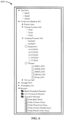
- FIG. 6 illustrates an example system model 600 provided to a user (via, e.g., the HMI 215 of the user device 110) according to some embodiments.
- the system model 600 may be provided as a hierarchical representation of the system model 600, where a user may interact with the hierarchical representation by expanding or collapsing one or more portions of the hierarchical representation.
- the electronic processor 200 may generate and transmit a hierarchical representation of the system model for display to a user.
- the system model 600 may include relationships between various components 150 of the industrial system 105.
- the system model 600 includes a group of silos (represented in FIG. 7 by reference numeral 705), as an example grouping relationship.
- the system model 600 also includes a process cell (represented in FIG. 7 by reference numeral 710), as an example containment relationship.
- the system model 600 also includes a set of recipes (represented in FIG. 7 by reference numeral 715), as an example application-specific relationship.
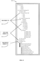
- FIG. 8 illustrates the system model 600 according to some embodiments were the system model 600 includes a mixture of S88 standard objects (represented in FIG. 8 by reference numeral 805), non-S88 objects (represented in FIG. 8 by reference numeral 810), and discrete manufacturing objects (represented in FIG. 8 by reference numeral 815). Accordingly, as illustrated by the example of FIG.
- a system model (e.g., the system model 600) may include objects associated with different capabilities.
- a system model may include default system model objects, batch control objects, non-batch control objects, and discrete objects.
- the system model 600 validates such that relative to each other, the S88 objects 805 follow the S88 rules (e.g., relationship rule associated with S88, such as batch control relationships defined as part of the S88 standard for batch control).
- S88 rules e.g., relationship rule associated with S88, such as batch control relationships defined as part of the S88 standard for batch control.
- Objects that are not of the S88 capability e.g., the non-S88 objects 810 and the discrete objects 815) follow the general validation rules for all objects. Accordingly, an object may be a member of more than one capability and will validate so long as it follows the rules (e.g., the relationship rules) of each capacity that the object belongs.
- the electronic processor 200 may enable implementation of one or more capabilities within the industrial system 105.
- the electronic processor may implement a capability within the industrial system 105 by configuring one or more components 150 associated with the at least one capability such that the one or more components 150 interact according to at least one relationship associated with the at least one capability to perform a function associated with the at least one capability.
- the electronic processor 200 implements one or more capabilities as part of the system metadata of the system model.
- the electronic processor 200 may check the configuration for correctness and consistency using the system metadata.
- the existence of the system metadata enables abilities such as checking configurations as they are entered, type ahead and automatic filling in of data, identifying undefined objects and relationships, and the like.
- the terms (including a reference to a "means") used to describe such components are intended to correspond, unless otherwise indicated, to any component which performs the specified function of the described component (e.g., a functional equivalent), even though not structurally equivalent to the disclosed structure, which performs the function in the herein illustrated exemplary aspects of the disclosed technology.
- the disclosed technology includes a system as well as a computer-readable medium having computer-executable instructions for performing the acts and/or events of the various methods of the invention.
Landscapes
- Engineering & Computer Science (AREA)
- Physics & Mathematics (AREA)
- Theoretical Computer Science (AREA)
- General Physics & Mathematics (AREA)
- Computer Hardware Design (AREA)
- Evolutionary Computation (AREA)
- Geometry (AREA)
- General Engineering & Computer Science (AREA)
- Automation & Control Theory (AREA)
- Management, Administration, Business Operations System, And Electronic Commerce (AREA)
Abstract
Description
- Not applicable.
- A system model generally refers to a representation of components (and associated relationships) of an industrial system. A system model may be used as a tool to conceptualize and construct industrial systems. Accordingly, a system model may be considered as the foundation of an industrial system.
- However, an end-user's industrial system is likely an amalgamation of "best in class" or "closest compromise" products from different industrial system vendors. Thus, the system model may include various combinations of different (a) control types (e.g., continuous, discrete, and batch), (b) automated processes and manual processes, and (c) application specifications unique to the end-user's implementation of the industrial system. These differences may impede naturally modeling an industrial system (e.g., the whole plant floor of an end-user). This may be problematic. The result may be that the foundation upon which the industrial system is built (e.g., the system model) is awkward and, ultimately, complicates numerous aspects of the industrial system, including, e.g., configuration and implementation of the industrial system. As a result, end-users are generally constrained by the limitations of the system model they use.
- The following presents a simplified summary of the disclosed technology herein in order to provide a basic understanding of some aspects of the disclosed technology. This summary is not an extensive overview of the disclosed technology. It is intended neither to identify key or critical elements of the disclosed technology nor to delineate the scope of the disclosed technology. Its sole purpose is to present some concepts of the disclosed technology in a simplified form as a prelude to the more detailed description that is presented later.
- The technology disclosed herein relates generally to industrial systems, and, more particularly, to modeling capabilities within system models of industrial systems.
- Embodiments described herein may leverage the abstract concept of objects when referring to components of an industrial system, such that users may construct capabilities (e.g., sets of objects that together follow a set of rules) that may then be implemented within a system model. The set of rules govern construction but also may be used to enforce the validity of the system model. This general method may be of great value for, e.g., building capabilities to support manufacturing standards, industry-specific solutions, customized systems for individual end-users, and the like. As such, embodiments described herein allow end-users a much greater degree of influence over modeling their factory as they operate it.
- Generally, a system model is a set of components with relationships, where the system model describes or represents an end-user's configuration of an industrial system (e.g., an end-user's factory or plant as a whole). As used herein, a "component" may include an industrial device (e.g., a conveyor belt, a pump, or the like), an industrial process (e.g., a recipe or the like), an industrial concept (e.g., a work shift or the like), or a combination thereof. The system model may be associated with system metadata (or system "grammar"). The system metadata may be a description of the set of components and their inter-relationships that provide a set of rules for configuring an industrial system (e.g., an end-user's configuration of a factory or plant). In some embodiments, a capability is a specialization that exists within a system model. Thus, a capability is a set of components with special relationships governing how the components interact with each other.
- In some embodiments, a system model may be implemented as an object-based system model such that each industrial asset (e.g., each component or device included in an industrial system) may be associated with an object definition. Accordingly, in some embodiments, the system model of an industrial system includes a plurality of objects (or "SmartObjects"), where each object represents an industrial asset of the industrial system. In some embodiments, the system model, via the implementation of objects, may use object inheritance features to propagate changes made to an object definition to all instances of the associated object used throughout a system model. A SmartObject may be an abstraction for a manufacturing entity. As used herein, a SmartObject (or object) may represent a component (physical or conceptual) or device with internal intelligence (e.g., such that the component or device may operate, at least to some extent, interactively and autonomously), such as a smart component or device. A system model may be considered a first capability, a set of SmartObjects that are related to each other by containment (e.g., this production line contains these pieces of equipment) and by grouping (e.g., those storage tanks are all part of a tank farm). A capability then is a configured set of SmartObjects that together follow a set of rules to implement a specific capability. The SmartObjects of a capability only pay attention to other SmartObjects of that capability when applying relationship rules, so the SmartObject may be part of many capabilities without affecting its membership. This allows the system model to host multiple capabilities and a SmartObj ect to be a member of many capabilities.
- Accordingly, embodiments described herein provide systems and methods for modeling different manufacturing capabilities within a system model by describing sets of components and the relationships between them and enforcing those relationships. One embodiment provides a system for modeling capabilities within system models of industrial systems. The system includes an electronic processor configured to receive a request for a system model of an industrial system associated with a set of components. The electronic processor is also configured to access system data associated with the industrial system. The electronic processor is also configured to generate, based on at least the system data, a system model such that the system model includes a set of capabilities associated with the industrial system, wherein each capability included in the set of capabilities is associated with a function of the industrial system. The electronic processor is also configured to enable transmission of the system model for display.
- Another embodiment provides a method for modeling capabilities within system models of industrial systems. The method includes receiving, with an electronic processor, a request for a system model of an industrial system associated with a set of components. The method also includes accessing, with the electronic processor, system data associated with the industrial system. The method also includes generating, with the electronic processor, based on at least the system data, a system model such that the system model includes a set of capabilities associated with the industrial system, wherein each capability included in the set of capabilities is associated with a function of the industrial system. The method also includes enabling, with the electronic processor, transmission of the system model for display.
- Yet another embodiment provides a non-transitory computer-readable medium storing instructions that, when executed by an electronic processor, perform a set of functions. The set of functions include receiving a request for a system model of an industrial system associated with a set of components. The set of functions also includes accessing system data associated with the industrial system. The set of functions also includes generating based on at least the system data, a system model such that the system model includes a set of capabilities associated with the industrial system, wherein each capability included in the set of capabilities is associated with a function of the industrial system. The set of functions also includes enabling transmission of the system model for display.
- The foregoing and other aspects and advantages of the present disclosure will appear from the following description. In the description, reference is made to the accompanying drawings which form a part hereof, and in which there is shown by way of illustrations one or more embodiments of the present disclosure. Such embodiments do not necessarily represent the full scope of the present disclosure, however, and reference is made therefore to the claims and herein for interpreting the scope of the present disclosure.
- The present disclosure will be better understood and features, aspects and advantages other than those set forth above will become apparent when consideration is given to the following detailed description thereof. Such detailed description makes reference to the following drawings.
-
FIG. 1 schematically illustrates a system for modeling capabilities within system models of industrial systems in accordance with some embodiments. -
FIG. 2 illustrates a user device of the system ofFIG. 1 according to some embodiments. -
FIG. 3 schematically illustrates an example system model for an industrial system implemented using batch control according to some embodiments. -
FIG. 4 schematically illustrates an example system model for an industrial system implemented using discreate manufacturing routes according to some embodiments. -
FIG. 5 is a flowchart illustrating a method for modeling capabilities within system models of industrial systems using the system ofFIG. 1 in accordance with some embodiments. -
FIGS. 6-8 illustrate an example system model according to some embodiments. - As utilized herein, terms "component," "system," "controller," "device," "manager," and variants thereof are intended to refer to a computer-related entity, either hardware, a combination of hardware and software, software, or software in execution. For example, a component may be, but is not limited to being, a process running on a processor, a processor, an object, an executable, a thread of execution, a program, and/or a computer. By way of illustration, both an application running on a server and the server may be a component. One or more components may reside within a process and/or thread of execution and a component may be localized on one computer and/or distributed between two or more computers.
- The disclosed technology is described with reference to the drawings, wherein like reference numerals are used to refer to like elements throughout. In the following description, for purposes of explanation, numerous specific details are set forth in order to provide a thorough understanding of the disclosed technology. It may be evident, however, that the disclosed technology may be practiced without these specific details. In other instances, well-known structures and devices are shown in block diagram form in order to facilitate describing the disclosed technology.
-
FIG. 1 schematically illustrates asystem 100 for modeling capabilities within system models of industrial systems according to some embodiments. In the illustrated example, thesystem 100 may include anindustrial system 105, auser device 110, and adatabase 115. In some embodiments, thesystem 100 includes fewer, additional, or different components in different configurations than illustrated inFIG. 1 . As one non-limiting example, thesystem 100 may include multipleindustrial systems 105,multiple user devices 110,multiple databases 115, or a combination thereof. As another non-limiting example, one or more components of thesystem 100 may be combined into a single device, such as, e.g., theuser device 110 and thedatabase 115. Alternatively, or in addition, in some embodiments, theuser device 110, thedatabase 115, or a combination thereof may be included as part of the industrial system 105 (e.g., as a component of the industrial system 105). - The
industrial system 105, theuser device 110, and thedatabase 115 may communicate over one or more wired orwireless communication networks 130. Portions of thecommunication networks 130 may be implemented using a wide area network, such as the Internet, a local area network, such as a BLUETOOTH® or WI-FI®, and combinations or derivatives thereof. Alternatively, or in addition, in some embodiments, components of thesystem 100 may communicate directly as compared to through thecommunication network 130. Also, in some embodiments, the components of thesystem 100 may communicate through one or more intermediary devices not illustrated inFIG. 1 . - The
industrial system 105 may be a manufacturing system, such as, e.g., an industrial automation system or the like. Theindustrial system 105 may be configured to perform one or more industrial processes, manufacturing processes, production processes, or the like. In some embodiments, theindustrial system 105 may perform a production method that produces goods or products. As one non-limiting example, theindustrial system 105 may perform a vehicle manufacturing processor to assemble or produce a vehicle (or various components thereof). As another non-limiting example, theindustrial system 105 may perform a food manufacturing process for making a food product. - In the illustrated example, the
industrial system 105 may include one ormore components 150. Acomponent 150 may include anindustrial device 152, anindustrial process 154, anindustrial concept 156, or another industrial asset of theindustrial system 105. - An
industrial device 152 may be a physical piece of equipment included in theindustrial system 105. For example, anindustrial device 152 may include a pump, a press, a conveyor, a valve, an industrial controller (e.g., a programmable logic controller ("PLC") and the like), a switch, a sensor, a server, a database, a human-machine interface ("HMI"), another piece of equipment that may be used in connection with an associated industrial process or application of theindustrial system 105, or the like. - An
industrial process 154 may be a procedure or method performed by the industrial system 105 (or a subset of industrial devices included therein). As one non-limiting example, anindustrial process 154 may include a recipe for manufacturing a food product, such as chicken stock, chocolate ice cream, or the like. - An
industrial concept 156 may be a concept associated with theindustrial system 105, such as, e.g., a state associated with theindustrial system 105, a capability associated with theindustrial system 105, or the like. The concept (e.g., a state, a capability, or the like) may be associated with theindustrial system 105 as a whole, one or moreindustrial devices 152 of theindustrial system 105, one or moreindustrial processes 154 of theindustrial system 105, or the like. As one non-limiting example, in some embodiments, theindustrial concept 156 may be a state of anindustrial device 152, such as, e.g., a clean state, an executing state, a resting state, or the like. As another non-limiting example, in some embodiments, theindustrial concept 156 may be a capability of anindustrial device 152, such as, e.g., a mixing capability, a storage capability, a heating capability, an assembly capability, or the like. As yet another non-limiting example, in some embodiments, theindustrial concept 156 may be a state of an industrial process, such as a state of a recipe (e.g., a started state, a finished state, an in-progress state, or the like). - The
user device 110 may be a computing device, such as a desktop computer, a laptop computer, a tablet computer, a terminal, a smart telephone, a smart television, a smart wearable, or another suitable computing device that interfaces with a user. As illustrated inFIG. 2 , theuser device 110 may include anelectronic processor 200, amemory 205, acommunication interface 210, and aHMI 215. Theelectronic processor 200, thememory 205, thecommunication interface 210, and theHMI 215 may communicate wirelessly, over one or more communication lines or buses, or a combination thereof. Theuser device 110 may include additional components than those illustrated inFIG. 2 in various configurations. Theuser device 110 may also perform additional functionality other than the functionality described herein. Also, the functionality (or a portion thereof) described herein as being performed by theuser device 110 may be distributed among multiple devices (e.g., as part of a cloud service or cloud-computing environment), combined with another component of the system 100 (e.g., combined with thedatabase 115, another component of thesystem 100, or the like), or a combination thereof. - The
communication interface 210 may include a transceiver that communicates with theindustrial system 105, thedatabase 115, or a combination thereof over thecommunication network 130 and, optionally, one or more other communication networks or connections. In some embodiments, thecommunication interface 210 enables theuser device 110 to communicate with theindustrial system 105, thedatabase 115, or a combination thereof over one or more wired or wireless connections. Theelectronic processor 200 may include a microprocessor, an application-specific integrated circuit ("ASIC"), or another suitable electronic device for processing data, and thememory 205 includes a non-transitory, computer-readable storage medium. Theelectronic processor 200 is configured to retrieve instructions and data from thememory 205 and execute the instructions. - As one non-limiting example, as illustrated in
FIG. 2 , thememory 205 may include a modeling application 260 (referred to herein as "theapplication 260"). Theapplication 260 may be a software application executable by theelectronic processor 200 in the example illustrated and as specifically discussed below, although a similarly purposed module may be implemented in other ways in other examples. Theelectronic processor 200 may execute theapplication 260 to facilitate system modeling, and, more specifically to facilitate modeling capabilities within system models of industrial systems (e.g., the industrial system 105). Alternatively, or in addition, theelectronic processor 200 may execute theapplication 260 to facilitate the implementation of a modeled capability (e.g., by configuring theindustrial system 105 based on a modeled capability such that theindustrial system 105 functions according to the modeled capability). - A capability may include a set of components and relationships between those components that describe a function or functional portion associated with the
industrial system 105. In some embodiments, a capability may be a default capability. A default capability may refer to a pre-existing or pre-established capability, such as, e.g., a capability established by a vendor or provider of the industrial system 105 (or a portion thereof). In some embodiments, a default capability includes pre-established or pre-existing objects and relationships of the system model, where the objects may be grouped together and can contain other objects. As one non-limiting example, when theindustrial system 105 includes a mixer component (e.g., a physical piece of equipment that mixes one or more materials), the default capability of that mixer component may be a mixing capability or function. In some embodiments, a capability may be established by an industry (e.g., the automotive industry, the textile industry, a food industry, or the like), an industrial system providing entity (e.g., an industrial system provider, vendor, or manufacturer), or the like. - Alternatively, or in addition, a capability may be a custom capability. A custom capability may be defined by an end user. For example, in some embodiments, a system model may be extended by using one or more capabilities (as a custom capability). In some embodiments, when a user configures an object of a capability (e.g., a custom capability), that object follows the rules associated with that capability (i.e., type of object, type of relationship(s), and the like). A custom capability may be based on a specific user application or implementation of the
industrial system 105. As one non-limiting example, a user may define a storage capability (as a custom capability) for the mixing component of the previous example, such that the mixing component performs a storage capability for one or more materials (as opposed to the default capability of mixing). Accordingly, a capability may be a user-defined or custom capability. As such, embodiments described herein enable an end-user to design and build capability models that fit their specific system specifications given a particular application or implementation of the industrial system 105 (e.g., by updating system metadata associated with the mixing component such that the system metadata includes a storage capability in addition to a mixing capability). Accordingly, in some embodiments, a capability is a specialization that exists within a system model (e.g., an existing system model for an end-user's current industrial system). - In some embodiments, a
component 150 of theindustrial system 105 may be associated with one or more capabilities. As one non-limiting example, following the previous example, the mixer component may be associated with a mixing capability (as a first capability) and a storage capability (as a second different capability). Accordingly, one or more of thecomponents 150 of theindustrial system 105 may be associated with multiple different capabilities. - As noted above, in some embodiments, a capability may include one or more relationships (also referred to herein collectively as "the relationship rules" and individually as "the relationship rule") provided by the associated set of components (e.g., one or more of the components 150). Accordingly, the relationship(s) may govern the functionality of the corresponding set of components 150 (such that the corresponding set of components perform the function associated with the capability). As such, in some instances the relationships may validate the system model.
- In some embodiments, a relationship may be a containment relationship. A containment relationship may be used to described
components 150 of theindustrial system 105 that are contained together (e.g., are included within a process cell). As one non-limiting example, when theindustrial system 105 performs an assembly process via three assembly stations, each assembly station has a containment relationship with the assembly line. - Alternatively, or in addition, in some embodiments, a relationship may be a grouping relationship. A grouping relationship may be used to describe
components 150 of theindustrial system 105 that share one or more common characteristics, such as, e.g., a state, a function, an associated capability, and the like. As one non-limiting example, when theindustrial system 105 includes two storage components and three mixing components, the two storage components may have a grouping relationship with each other because each storage component provides a storage function while the three mixing components may have a grouping relationship with each other because each mixing component provides a mixing function. Accordingly, in some embodiments, the grouping relationships may enable an end-user to perform various searching functions, filtering functions, or the like (based on one or more common characteristics) with respect to the industrial system 150 (e.g., within the system model of the industrial system 105). - Alternatively, or in addition, in some embodiments, a relationship may be an application-specific relationship. An application-specific relationship may be a custom relationship defined by an end-user. A custom relationship may be based on a specific user application or implementation of the
industrial system 105. As one non-limiting example, a custom relationship may allow a specific route or path between one or moreindustrial devices 152, such as, e.g., a conditional material transfer route or the like. An application-specific relationship may have a specific set of rules that govern the associated components. As one non-limiting example, when a user may have a recipe for producing an end-product, the components involved in producing the end-product (according to the recipe) may have an application-specific relationship. - As noted above, in some embodiments, the functionality (or a portion thereof) described herein as being performed by the
user device 110 may be distributed among multiple devices (e.g., as part of a cloud service or cloud-computing environment). As one non-limiting example, in some embodiments, thesystem 100 may include a server (e.g., a computing device). The server may include similar components as theuser device 110, such as an electronic processor (e.g., a microprocessor, an ASIC, or another suitable electronic device), a memory (e.g., a non-transitory, computer-readable storage medium), a communication interface, such as a transceiver, for communicating over thecommunication network 130 and, optionally, one or more additional communication networks or connections. Accordingly, in some embodiments, the server may store theapplication 260 as part of providing a system modeling and configuration service through the server. In such embodiments, to communicate with the server (e.g., interact with the application 260), theuser device 110 may store abrowser application 262 or adedicated software application 264 executable by the user deviceelectronic processor 200. - As noted above, the
user device 110 may also include theHMI 215 for interacting with a user. TheHMI 215 may include one or more input devices, one or more output devices, or a combination thereof. Accordingly, in some configurations, theHMI 215 allows a user to interact with (e.g., provide input to and receive output from) theuser device 210. For example, theHMI 215 may include a keyboard, a cursor-control device (e.g., a mouse), a touch screen, a scroll ball, a mechanical button, a display device (e.g., a liquid crystal display ("LCD")), a printer, a speaker, a microphone, another type of input device, another type of output device, or a combination thereof. As illustrated inFIG. 2 , in some embodiments, theHMI 215 includes adisplay device 270. Thedisplay device 270 may be included in the same housing as theuser device 110 or may communicate with theuser device 110 over one or more wired or wireless connections. For example, in some configurations, thedisplay device 270 is a touchscreen included in a laptop computer or a tablet computer. In other configurations, thedisplay device 270 is a monitor, a television, or a projector coupled to a terminal, desktop computer, or the like via one or more cables. - Returning to
FIG. 1 , thesystem 100 may also include thedatabase 115. Thedatabase 115 may store system data associated with theindustrial system 105. System data may include a set ofcomponents 150 included in the industrial system 105 (e.g., the industrial device(s) 152, the industrial process(es) 154 of theindustrial system 105, the industrial concept(s) 156, or a combination thereof). Alternatively, or in addition, the system data may include one or more relationships (or set of relationship rules) associated with the industrial system 105 (e.g., the containment relationship(s), the grouping relationship(s), the application-specific relationship(s), other relationship data, or a combination thereof). Alternatively, or in addition, the system data may include one or more modeled capabilities associated with the system model of theindustrial system 105. In some embodiments, the system data is accessed (via, e.g., theelectronic processor 200 executing the application 260) as part of modeling capabilities within system models of industrial systems, implementing modeled capabilities within theindustrial system 105, or the like. Accordingly, thedatabase 115 may store data associated with the system model of theindustrial system 105. - As noted above, in some embodiments, two or more components of the
system 100 may be combined into a single component. As one non-limiting example, in some embodiments, thedatabase 115 and theuser device 110 may be combined, such that the data stored in the database 115 (e.g., the system data) may be stored in thememory 205 of theuser device 110. -
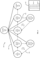
FIG. 3 illustrates anexample system model 300 for an industrial system (e.g., the industrial system 105) implemented using batch control according to some embodiments.FIG. 3 also illustrates ahierarchical representation 302 of thesystem model 300. According to the example ofFIG. 3 , thesystem model 300 may include a set of industrial devices (e.g., the industrial device(s) 152). In some instance, an industrial system 105 (including thecomponents 150 therein) are represented as objects (e.g., a set of SmartObjects). As noted herein, "object" may reference an abstract data type representing the industrial system 105 (including thecomponents 150 therein). As illustrated inFIG. 3 , the set of objects includes an icecream factory object 304, awest parlor object 305, amixing tank object 310, astorage tank object 315, anagitator object 320, afeed valve object 325, a transfer-outvalve object 330, a transfer-invalve object 335, adrain manifold object 340, and adrainage valve object 345. - As further illustrated in
FIG. 3 , the set of objects may be organized into various subsections: anarea level 349, aprocess cell level 350, aunit level 355, and an equipment level 360 (e.g., as part of a batch control capability), where each subsection represents a relationship between the objects. Thearea level 349 designates an area (e.g., a physical geographical space or region) associated with the industrial system 105 (e.g., an ice cream factory according to the example illustrated inFIG. 3 ). Theprocess cell level 350 designates a process level associated with theindustrial system 105. Theunit level 355 designates one or more units associated with the process of theprocess cell level 350. As illustrated inFIG. 3 , theunit level 355 includes themixing tank object 310 and the storage tank object 315 (as the one or more units). Theequipment level 360 designates equipment (e.g., one or more industrial devices 152) of the unit(s) associated with the process of theprocess cell level 350. As illustrated inFIG. 3 , theequipment level 360 includes theagitator object 320, thefeed valve object 325, the transfer-outvalve object 330, the transfer-invalve object 335, thedrain manifold object 340, and thedrainage valve object 345. - As illustrated in
FIG. 3 , thesystem model 300 may include a set of containment rules (represented by asolid line 362 inFIG. 3 ). In some embodiments, a containment rule may establish or represent a containment relationship (as described in greater detail herein). As one non-limiting example, thewest parlor object 305 has a containment relationship with themixing tank object 310 and thestorage tank object 315. Following this example, the physical mixing tank and the physical storge tank (represented by themixing tank object 310 and thestorage tank object 315, respectively) are contained (or located) in the physical west parlor (represented by the west parlor object 310). As yet another non-limiting example, themixing tank object 310 has a containment relationship with theagitator object 320, thefeed valve object 325, and the transfer-outvalve object 330. Following this example, the physical mixing tank (represented by the mixing tank object 310) includes an agitator, a feed valve, and a transfer-out valve (represented by theagitator object 320, thefeed valve object 325, and the transfer-outvalve object 330, respectively). - Additionally, the
system model 300 ofFIG. 3 may include one or more special relationships, including flow paths between units and material transfers between equipment phases. A special relationship may include, e.g., a relationship that is not a refinement of a default relationships (e.g., a containment relationship, a grouping relationship, etc.). In the illustrated example ofFIG. 3 , thesystem model 300 includes aunit flow path 365 and an equipment transfer path 370 (as special relationships). Theunit flow path 365 is between the mixing tank (represented by the mixing tank object 310) and the storage tank (represented by the storage tank object 315). As illustrated, theequipment transfer path 370 is between the transfer-out valve (represented by the transfer-out valve object 330) and the transfer-in valve (represented by the transfer-in valve object 330). Theequipment transfer path 370 represents a transfer of material between the transfer-out valve (represented by the transfer-out valve object 330) and the transfer-in valve (represented by the transfer-in valve object 330). - As another example,
FIG. 4 illustrates anexample system model 400 for an industrial system (e.g., the industrial system 105) implemented using discreate manufacturing routes according to some embodiments.FIG. 4 also illustrates ahierarchical representation 402 of thesystem model 400. According to the example ofFIG. 4 , thesystem model 400 may include a set of objects. In the illustrated example, the objects are associated with industrial components (e.g., one or more of the industrial devices 152) of an industrial system (e.g., the industrial system 105). In some embodiments, one or more of the objects may be autonomous objects. As illustrated inFIG. 4 , the set of objects includes anassembly line object 405, afirst station object 410, asecond station object 415, a secondstation rework object 420, athird station object 425, afourth station object 430, a fourthstation rework object 435, and acomplete bin object 440. - As illustrated in
FIG. 4 , thesystem model 400 may include a set of containment rules (represented by asolid line 445 inFIG. 4 ). As one non-limiting example, the assembly line (represented by the assembly line object 405) has a containment relationship with the first station, the second station, the second station rework, the third station, the fourth station, the fourth station rework, and the complete bin (represented by thefirst station object 410, thesecond station object 415, the secondstation rework object 420, thethird station object 425, thefourth station object 430, the fourthstation rework object 435, and thecomplete bin object 440, respectively). Following this example, the assembly line (represented by the assembly line object 405) includes the first station, the second station, the second station rework, the third station, the fourth station, the fourth station rework, and the complete bin (represented by thefirst station object 410, thesecond station object 415, the secondstation rework object 420, thethird station object 425, thefourth station object 430, the fourthstation rework object 435, and thecomplete bin object 440, respectively). - Additionally, the
system model 400 ofFIG. 4 may include one or more special relationships for conditional paths between workstations (represented inFIG. 4 as a dashed line 446). In the illustrated example ofFIG. 4 , thesystem model 400 may include a first conditional route path (represented inFIG. 4 by the arrow 450) between thefirst station object 410, thesecond station object 415, and the secondstation rework object 420. As one non-limiting example, the firstconditional route path 450 may be followed when a product does not pass a predetermined threshold associated with thesecond station object 415. Similarly, as another non-limiting example, a second conditional route path (represented inFIG. 4 by the arrow 455) may be followed when a product does not pass a predetermined threshold associated with thefourth station object 430. - Alternatively, or in addition, in some embodiments, a state machine may be configured as an extension capability. As one non-limiting example, highly state-based machine behavior may be configured as a capability. In such embodiments, the system model may include a set of objects (e.g., state objects). Each state may describe its name and one or more actions that the state performs. The set of state objects may have containment rules (as similarly described above with respect to
FIGS. 3 and4 ). Alternatively, or in addition, the set of state objects may have special relationships, such as for conditional paths between states (as similarly described above with respect toFIGS. 3 and4 ). As one non-limiting example, a special relationship may include a custom relationship whose rule defines when a state transition occurs, making its source inactive and the state it points to active (e.g., as a state transition). -
FIG. 5 is a flowchart illustrating anexample method 500 for modeling capabilities within system models of industrial systems according to some embodiments. Themethod 500 is described herein as being performed by the user device 110 (e.g., theelectronic processor 200 executing the application 260). - As illustrated in
FIG. 5 , themethod 500 includes receiving, with theelectronic processor 200, a request for a system model of the industrial system 105 (at block 505). In some embodiments, theelectronic processor 200 receives the request from a user interacting with the user device (via, e.g., the HMI 215). As described in greater detail herein, the system model includes a set of components (e.g., one or more of the components 150) with relationships, where each relationship governs interaction between at least two components included in the set of components. - The
electronic processor 200 may then access system data associated with the industrial system 105 (at block 510). As noted above, the system data may be stored remotely in thedatabase 115. Accordingly, in some embodiments, theelectronic processor 200 may access the system data from the database 115 (over the communication network 130). Alternatively, or in addition, in some embodiments, the system data may be locally stored in thememory 205 of theuser device 110. In such embodiments, theelectronic processor 200 may access the system data from thememory 205. As described in greater detail herein, the system data may include a set ofcomponents 150 included in the industrial system 105 (e.g., the industrial device(s) 152, the industrial process(es) 154 of theindustrial system 105, the industrial concept(s) 156, or a combination thereof), one or more relationships (or set of relationship rules) associated with the industrial system 105 (e.g., the containment relationship(s), the grouping relationship(s), the application-specific relationship(s), other relationship data, or a combination thereof), one or more modeled capabilities associated with the system model of theindustrial system 105, or the like. - Based on at least the system data, the
electronic processor 200 may generate the system model such that the system model includes a set of capabilities associated with the industrial system 105 (at block 515). As described in greater detail herein, a capability is a set of components and relationships between those components that describe a function or functional portion of theindustrial system 105. In some embodiments, the capability is a specialization that exists within a system model. - Alternatively, or in addition, in some embodiments, the
electronic processor 200 may receive a user input defining a new capability (e.g., a custom extension to an existing system model). In such embodiments, the user input may indicate a set of components (e.g., a new subset ofcomponents 150 of the industrial system 105), a new relationship between those components (e.g., a custom relationship defined by the user, such as a relationship that aligns with an end-user's application or implementation of the industrial system 105), or a combination thereof. In response to receiving the user input, theelectronic processor 200 may generate (or re-generate) the system model such that the system model includes the new capability. - After generating the system model (at block 515), the
electronic processor 200 may then enable transmission of the system model for display (at block 520). In some embodiments, theelectronic processor 200 transmits the system model for display to a user via theHMI 215. When the system model is displayed to the user via theHMI 215, theelectronic processor 200 may enable a user to interact with the system model. A user may interact with the system model by viewing the system model. Alternatively, or in addition, the user may interact with the system model by providing user input with respect to the system model (or the industrial system 105). - As one non-limiting example,
FIG. 6 illustrates anexample system model 600 provided to a user (via, e.g., theHMI 215 of the user device 110) according to some embodiments. As illustrated inFIG. 6 , in some embodiments, thesystem model 600 may be provided as a hierarchical representation of thesystem model 600, where a user may interact with the hierarchical representation by expanding or collapsing one or more portions of the hierarchical representation. Accordingly, in some embodiments, theelectronic processor 200 may generate and transmit a hierarchical representation of the system model for display to a user. - As illustrated in
FIG. 7 , thesystem model 600 may include relationships betweenvarious components 150 of theindustrial system 105. In the illustrated example, thesystem model 600 includes a group of silos (represented inFIG. 7 by reference numeral 705), as an example grouping relationship. Thesystem model 600 also includes a process cell (represented inFIG. 7 by reference numeral 710), as an example containment relationship. Thesystem model 600 also includes a set of recipes (represented inFIG. 7 by reference numeral 715), as an example application-specific relationship. - As noted herein, a
component 150 of theindustrial system 105 may be associated with one or more capabilities. Accordingly, each system model extension may coexist within the same system model without affecting each other. System model extension objects may follow the relationship rules of their capability relative to each other, where objects that are not of the same capability may ignore non-members. As such, an object may implement multiple capabilities. As one non-limiting example,FIG. 8 illustrates thesystem model 600 according to some embodiments were thesystem model 600 includes a mixture of S88 standard objects (represented inFIG. 8 by reference numeral 805), non-S88 objects (represented inFIG. 8 by reference numeral 810), and discrete manufacturing objects (represented inFIG. 8 by reference numeral 815). Accordingly, as illustrated by the example ofFIG. 8 , in some embodiments, a system model (e.g., the system model 600) may include objects associated with different capabilities. For example, as illustrated in the example ofFIG. 8 , in some embodiments, a system model may include default system model objects, batch control objects, non-batch control objects, and discrete objects. In the illustrated example, thesystem model 600 validates such that relative to each other, the S88 objects 805 follow the S88 rules (e.g., relationship rule associated with S88, such as batch control relationships defined as part of the S88 standard for batch control). Objects that are not of the S88 capability (e.g., the non-S88 objects 810 and the discrete objects 815) follow the general validation rules for all objects. Accordingly, an object may be a member of more than one capability and will validate so long as it follows the rules (e.g., the relationship rules) of each capacity that the object belongs. - Alternatively, or in addition, in some embodiments, the
electronic processor 200 may enable implementation of one or more capabilities within theindustrial system 105. In some embodiments, the electronic processor may implement a capability within theindustrial system 105 by configuring one ormore components 150 associated with the at least one capability such that the one ormore components 150 interact according to at least one relationship associated with the at least one capability to perform a function associated with the at least one capability. In some embodiments, theelectronic processor 200 implements one or more capabilities as part of the system metadata of the system model. Thus, theelectronic processor 200 may check the configuration for correctness and consistency using the system metadata. The existence of the system metadata enables abilities such as checking configurations as they are entered, type ahead and automatic filling in of data, identifying undefined objects and relationships, and the like. - What has been described above includes examples of the disclosed technology. It is, of course, not possible to describe every conceivable combination of components or methodologies for purposes of describing the disclosed technology, but one of ordinary skill in the art may recognize that many further combinations and permutations of the disclosed technology are possible. Accordingly, the disclosed technology is intended to embrace all such alterations, modifications, and variations that fall within the spirit and scope of the appended claims.
- In particular and in regard to the various functions performed by the above described components, devices, circuits, systems and the like, the terms (including a reference to a "means") used to describe such components are intended to correspond, unless otherwise indicated, to any component which performs the specified function of the described component (e.g., a functional equivalent), even though not structurally equivalent to the disclosed structure, which performs the function in the herein illustrated exemplary aspects of the disclosed technology. In this regard, it will also be recognized that the disclosed technology includes a system as well as a computer-readable medium having computer-executable instructions for performing the acts and/or events of the various methods of the invention.
- In addition, while a particular feature of the disclosed technology may have been disclosed with respect to only one of several implementations, such feature may be combined with one or more other features of the other implementations as may be desired and advantageous for any given or particular application. Furthermore, to the extent that the terms "includes," and "including" and variants thereof are used in either the detailed description or the claims, these terms are intended to be inclusive in a manner similar to the term "comprising."
Claims (15)
- A system for modeling capabilities within system models of industrial systems, the system comprising:
an electronic processor configured toreceive a request for a system model of an industrial system associated with a set of components,access system data associated with the industrial system,generate, based on at least the system data, a system model such that the system model includes a set of capabilities associated with the industrial system, wherein each capability included in the set of capabilities is associated with a function of the industrial system, andenable transmission of the system model for display. - The system of claim 1, wherein the system model includes a set of components with relationships, wherein each relationship governs interaction between at least two components included in the set of components.
- The system of claim 1 or 2, wherein each capability includes a subset of components included in the set of components and at least one relationship between at least two components included in the subset of components.
- The system of claim 3, at least one of:wherein the at least one relationship governs interaction between the at least two components; andwherein the at least one relationship is a custom relationship defined by an end-user based on an application of the industrial system.
- The system of one of claims 1 to 4, wherein the set of components includes a first component and a second component, wherein the first component is associated with a first capability of the set of capabilities and the second component is associated with a second capability of the set of capabilities, wherein the first capability is different from the second capability.
- The system of one of claims 1 to 5, wherein the electronic processor is further configured to
receive a user input defining a new capability, the user input indicating a custom relationship between two or more components included in the set of components, wherein the system model includes the new capability. - The system of claim 6, wherein the user input indicates a new subset of components, the new subset of components including the two or more components.
- The system of one of claims 1 to 7, wherein the electronic processor is further configured to enable implementation of the at least one capability via the industrial system.
- The system of claim 8, wherein the electronic processor is further configured to enable implementation of the at least one capability by configuring one or more components associated with the at least one capability such that the one or more components interact according to at least one relationship associated with the at least one capability to perform a function associated with the at least one capability.
- The system of one of claims 1 to 9, at least one of:wherein the data associated with the industrial system includes a set of components, wherein the set of components includes at least one selected from a group consisting of a device associated with the industrial system, a state associated with the industrial system, and a process associated with the industrial system; andwherein the electronic processor is further configured to generate a hierarchical representation of the system model for display.
- A method for modeling capabilities within system models of industrial systems, the method comprising:receiving, with an electronic processor, a request for a system model of an industrial system associated with a set of components;accessing, with the electronic processor, system data associated with the industrial system;generating, with the electronic processor, based on at least the system data, a system model such that the system model includes a set of capabilities associated with the industrial system, wherein each capability included in the set of capabilities is associated with a function of the industrial system; andenabling, with the electronic processor, transmission of the system model for display.
- The method of claim 11, further comprising:receiving a user input defining a new capability, the user input indicating a custom relationship between two or more components included in the set of components,wherein generating the system model includes generating the system model based at least in part on the new capability.
- The method of claim 11 or 12, at least one of:wherein generating the system model includes generating the system model such that each capability includes a subset of components included in the set of components and at least one relationship between at least two components included in the subset of components, wherein the at least one relationship is a custom relationship defined by an end-user based on an application of the industrial system; andwherein generating the system model includes generating a system model that includes a set of components including a first component and a second component, wherein the first component is associated with a first capability of the set of capabilities and the second component is associated with a second capability of the set of capabilities, wherein the first capability is different from the second capability.
- A non-transitory computer-readable medium storing instructions that, when executed by an electronic processor, perform a set of functions, the set of functions comprising:receiving a request for a system model of an industrial system associated with a set of components;accessing system data associated with the industrial system;generating based on at least the system data, a system model such that the system model includes a set of capabilities associated with the industrial system, wherein each capability included in the set of capabilities is associated with a function of the industrial system; andenabling transmission of the system model for display.
- The computer-readable medium of claim 14, at least one of:
wherein the set of functions further include:receiving a user input defining a new capability, the user input indicating a custom relationship between two or more components included in the set of components,wherein generating the system model includes generating the system model based at least in part on the new capability;wherein the set of functions further include:enabling implementation of the at least one capability by configuring one or more components associated with the at least one capability such that the one or more components interact according to at least one relationship associated with the at least one capability to perform a function associated with the at least one capability; andwherein the set of functions further include:
generating a hierarchical representation of the system model for display.
Applications Claiming Priority (1)
| Application Number | Priority Date | Filing Date | Title |
|---|---|---|---|
| US17/901,828 US20240078354A1 (en) | 2022-09-01 | 2022-09-01 | System and methods for modeling capabilities within system models of industrial systems |
Publications (1)
| Publication Number | Publication Date |
|---|---|
| EP4332697A1 true EP4332697A1 (en) | 2024-03-06 |
Family
ID=87551114
Family Applications (1)
| Application Number | Title | Priority Date | Filing Date |
|---|---|---|---|
| EP23187245.8A Pending EP4332697A1 (en) | 2022-09-01 | 2023-07-24 | System and methods for modeling capabilities within system models of industrial systems |
Country Status (2)
| Country | Link |
|---|---|
| US (1) | US20240078354A1 (en) |
| EP (1) | EP4332697A1 (en) |
Citations (3)
| Publication number | Priority date | Publication date | Assignee | Title |
|---|---|---|---|---|
| US20060282252A1 (en) * | 2005-05-31 | 2006-12-14 | The Mathworks, Inc. | Modeling of a multiprocessor system |
| US20160085520A1 (en) * | 2013-05-31 | 2016-03-24 | Huawei Technologies Co., Ltd. | Application Creation Method and Apparatus |
| WO2022030567A1 (en) * | 2020-08-06 | 2022-02-10 | オムロン株式会社 | Display system, display method, and display program |
Family Cites Families (1)
| Publication number | Priority date | Publication date | Assignee | Title |
|---|---|---|---|---|
| US20150066163A1 (en) * | 2013-08-28 | 2015-03-05 | Honeywell International Inc. | System and method for multi-domain structural analysis across applications in industrial control and automation system |
-
2022
- 2022-09-01 US US17/901,828 patent/US20240078354A1/en active Pending
-
2023
- 2023-07-24 EP EP23187245.8A patent/EP4332697A1/en active Pending
Patent Citations (4)
| Publication number | Priority date | Publication date | Assignee | Title |
|---|---|---|---|---|
| US20060282252A1 (en) * | 2005-05-31 | 2006-12-14 | The Mathworks, Inc. | Modeling of a multiprocessor system |
| US20160085520A1 (en) * | 2013-05-31 | 2016-03-24 | Huawei Technologies Co., Ltd. | Application Creation Method and Apparatus |
| WO2022030567A1 (en) * | 2020-08-06 | 2022-02-10 | オムロン株式会社 | Display system, display method, and display program |
| EP4194981A1 (en) * | 2020-08-06 | 2023-06-14 | OMRON Corporation | Display system, display method, and display program |
Also Published As
| Publication number | Publication date |
|---|---|
| US20240078354A1 (en) | 2024-03-07 |
Similar Documents
| Publication | Publication Date | Title |
|---|---|---|
| CN107976971B (en) | Alarm handling and viewing support in a process plant | |
| US8862536B2 (en) | Graphical user interface | |
| US9965562B2 (en) | Industrial automation app-store | |
| US11774927B2 (en) | Methods and apparatus to provide a role-based user interface | |
| US20200103879A1 (en) | System and Method for Implementing a User Interface to a Multi-Agent Distributed Control System | |
| CN110874447B (en) | Systems and methods for embedding web frames in process graphs | |
| JP4908219B2 (en) | Configurable PLC and SCADA based control system and method | |
| US9256219B2 (en) | System configuration using templates | |
| TW202113586A (en) | Method and device for generating applet | |
| US9124445B2 (en) | Apparatus for integrating device objects into a superordinated control unit | |
| JP2019075107A (en) | System and method for automatically inputting display area with historized process parameter | |
| US20150106826A1 (en) | Apparatus for servicing at least one field device of automation technology | |
| US20090177970A1 (en) | Method for online servicing of a field device of automation technology | |
| GB2535597A (en) | Methods and apparatus to provide a role-based user interface | |
| US20150105885A1 (en) | Adaptive filtering in industrial control system | |
| US12360515B2 (en) | Industrial automation system topology with point to point representation paths | |
| CN104102196A (en) | Batch production-based industrial automatic control system | |
| US20240264832A1 (en) | Industrial automation system topology with point to point business rule integration | |
| US20240078354A1 (en) | System and methods for modeling capabilities within system models of industrial systems | |
| Lober et al. | Improving the engineering process of control systems based on digital twin specifications | |
| EP4325795A1 (en) | Background discovery agent orchestration | |
| US20250138789A1 (en) | System and method for device profile creation in an integrated development environment | |
| EP4336282A1 (en) | A method for connecting a web socket session with an object instance with automation device association | |
| EP4307105A1 (en) | Extensible profiles for industrial control modules | |
| CN114492051B (en) | Digital workshop dynamic reconstruction method, device, equipment and storage medium |
Legal Events
| Date | Code | Title | Description |
|---|---|---|---|
| PUAI | Public reference made under article 153(3) epc to a published international application that has entered the european phase |
Free format text: ORIGINAL CODE: 0009012 |
|
| STAA | Information on the status of an ep patent application or granted ep patent |
Free format text: STATUS: THE APPLICATION HAS BEEN PUBLISHED |
|
| AK | Designated contracting states |
Kind code of ref document: A1 Designated state(s): AL AT BE BG CH CY CZ DE DK EE ES FI FR GB GR HR HU IE IS IT LI LT LU LV MC ME MK MT NL NO PL PT RO RS SE SI SK SM TR |
|
| STAA | Information on the status of an ep patent application or granted ep patent |
Free format text: STATUS: REQUEST FOR EXAMINATION WAS MADE |
|
| 17P | Request for examination filed |
Effective date: 20240902 |
|
| RBV | Designated contracting states (corrected) |
Designated state(s): AL AT BE BG CH CY CZ DE DK EE ES FI FR GB GR HR HU IE IS IT LI LT LU LV MC ME MK MT NL NO PL PT RO RS SE SI SK SM TR |