EP4332647A2 - Optischer lichtleiter, endoskop, verfahren zur herstellung und verwendung eines optischen lichtleiters - Google Patents
Optischer lichtleiter, endoskop, verfahren zur herstellung und verwendung eines optischen lichtleiters Download PDFInfo
- Publication number
- EP4332647A2 EP4332647A2 EP24152947.8A EP24152947A EP4332647A2 EP 4332647 A2 EP4332647 A2 EP 4332647A2 EP 24152947 A EP24152947 A EP 24152947A EP 4332647 A2 EP4332647 A2 EP 4332647A2
- Authority
- EP
- European Patent Office
- Prior art keywords
- sheath
- light guide
- optic light
- bundle
- endoscope
- Prior art date
- Legal status (The legal status is an assumption and is not a legal conclusion. Google has not performed a legal analysis and makes no representation as to the accuracy of the status listed.)
- Pending
Links
Images

Classifications
-
- A—HUMAN NECESSITIES
- A61—MEDICAL OR VETERINARY SCIENCE; HYGIENE
- A61B—DIAGNOSIS; SURGERY; IDENTIFICATION
- A61B1/00—Instruments for performing medical examinations of the interior of cavities or tubes of the body by visual or photographical inspection, e.g. endoscopes; Illuminating arrangements therefor
- A61B1/06—Instruments for performing medical examinations of the interior of cavities or tubes of the body by visual or photographical inspection, e.g. endoscopes; Illuminating arrangements therefor with illuminating arrangements
- A61B1/07—Instruments for performing medical examinations of the interior of cavities or tubes of the body by visual or photographical inspection, e.g. endoscopes; Illuminating arrangements therefor with illuminating arrangements using light-conductive means, e.g. optical fibres
-
- A—HUMAN NECESSITIES
- A61—MEDICAL OR VETERINARY SCIENCE; HYGIENE
- A61B—DIAGNOSIS; SURGERY; IDENTIFICATION
- A61B1/00—Instruments for performing medical examinations of the interior of cavities or tubes of the body by visual or photographical inspection, e.g. endoscopes; Illuminating arrangements therefor
- A61B1/00064—Constructional details of the endoscope body
- A61B1/0011—Manufacturing of endoscope parts
-
- G—PHYSICS
- G02—OPTICS
- G02B—OPTICAL ELEMENTS, SYSTEMS OR APPARATUS
- G02B23/00—Telescopes, e.g. binoculars; Periscopes; Instruments for viewing the inside of hollow bodies; Viewfinders; Optical aiming or sighting devices
- G02B23/24—Instruments or systems for viewing the inside of hollow bodies, e.g. fibrescopes
- G02B23/2407—Optical details
- G02B23/2461—Illumination
- G02B23/2469—Illumination using optical fibres
-
- G—PHYSICS
- G02—OPTICS
- G02B—OPTICAL ELEMENTS, SYSTEMS OR APPARATUS
- G02B23/00—Telescopes, e.g. binoculars; Periscopes; Instruments for viewing the inside of hollow bodies; Viewfinders; Optical aiming or sighting devices
- G02B23/24—Instruments or systems for viewing the inside of hollow bodies, e.g. fibrescopes
- G02B23/2476—Non-optical details, e.g. housings, mountings, supports
-
- G—PHYSICS
- G02—OPTICS
- G02B—OPTICAL ELEMENTS, SYSTEMS OR APPARATUS
- G02B23/00—Telescopes, e.g. binoculars; Periscopes; Instruments for viewing the inside of hollow bodies; Viewfinders; Optical aiming or sighting devices
- G02B23/24—Instruments or systems for viewing the inside of hollow bodies, e.g. fibrescopes
- G02B23/26—Instruments or systems for viewing the inside of hollow bodies, e.g. fibrescopes using light guides
-
- G—PHYSICS
- G02—OPTICS
- G02B—OPTICAL ELEMENTS, SYSTEMS OR APPARATUS
- G02B6/00—Light guides; Structural details of arrangements comprising light guides and other optical elements, e.g. couplings
- G02B6/04—Light guides; Structural details of arrangements comprising light guides and other optical elements, e.g. couplings formed by bundles of fibres
- G02B6/06—Light guides; Structural details of arrangements comprising light guides and other optical elements, e.g. couplings formed by bundles of fibres the relative position of the fibres being the same at both ends, e.g. for transporting images
-
- G—PHYSICS
- G02—OPTICS
- G02B—OPTICAL ELEMENTS, SYSTEMS OR APPARATUS
- G02B6/00—Light guides; Structural details of arrangements comprising light guides and other optical elements, e.g. couplings
- G02B6/24—Coupling light guides
- G02B6/241—Light guide terminations
-
- G—PHYSICS
- G02—OPTICS
- G02B—OPTICAL ELEMENTS, SYSTEMS OR APPARATUS
- G02B6/00—Light guides; Structural details of arrangements comprising light guides and other optical elements, e.g. couplings
- G02B6/24—Coupling light guides
- G02B6/36—Mechanical coupling means
- G02B6/40—Mechanical coupling means having fibre bundle mating means
Definitions
- the invention relates to an optic light guide having a bundle of a plurality of light-guiding single fibres and at least one sheath covering at least one section of an outer circumference of the bundle.
- the invention additionally relates to an endoscope having an optic light guide.
- the invention furthermore relates to a method for producing an optic light guide.
- the invention relates to the use of an optic light guide for the purpose of guiding light between a proximal end of the shaft and a distal end of the shaft.
- Light guides of the kind referred to above are already known. They are used in endoscopes for the purpose of guiding light of a light source from a proximal end to a distal end of the endoscope shaft to illuminate a spot in a cavity that is to be examined, for example.
- light guides can guide images that are captured at the front of the endoscope (field of view) to an image sensor at the proximal end of the endoscope (e.g. in the handle of the endoscope). In this case, the light guides are guiding light reflected from the tissue to the imager.
- the optic light guides For the purpose of producing the optic light guides, it has become common practice to firmly enclose bundles consisting of a plurality of light-guiding single fibres by means of a sheath, which allows the single fibres to be packed with the maximum density possible. Subsequently, if the sheath is an end sheath, for example, the bundle can be trimmed to the desired length and abraded and/or polished to form an even end.
- the sheath thus constitutes a fibre sleeve of the optic light guide.
- optic light guides take up a relatively large amount of installation space, for example when they are installed in an endoscope. Since endoscopes are often introduced into narrow cavities to examine them, it is desirable to design endoscopes with an endoscope shaft that is as narrow (or as thin) as possible. As light guides are arranged along the longitudinal axis of the endoscope shaft, a diameter of the shaft is defined to a significant extent by the thickness of the optic light guide.
- the weight of the optic light guide is to be kept as low as possible, as a user usually also has to lift the weight of the optic light guide installed in the endoscope, for example, when using the endoscope.
- the invention may provide on occasion for an alignment of the front face (light entry surface and/or light exit surface) being formed by the light guide in the area of an endoscope tip that is not perpendicular to the longitudinal axis of the light guide or the endoscope shaft, but transversally (or at an angle) to the light guide or the endoscope shaft.
- reflection surfaces such as mirrors are often used which, however, take up additional installation space and sometimes increase the overall weight of the optic light guide.
- An object of at least some embodiments of the invention is to improve the properties of use of previously known optic light guides and/or endoscopes of the kind mentioned above.
- an optic light guide according to claim 1 is provided.
- an optic light guide of the kind mentioned above is provided, wherein the at least one sheath is made of ceramic.
- the at least one sheath is made of ceramic. This has the advantage that a shape can be selected very easily, and that the material of the sheath is solid and hard enough to provide stability and robustness.
- ceramic sheaths have a surface which is relatively smooth compared with other materials (such as metal) and which facilitates the insertion of single fibres as a bundle and the setting of the desired density of the bundle.
- ceramic is an electrically non-conductive material, which means that the sheath provides additional insulation to electronic components, e.g. to an imaging module or image sensor. Therefore, additional insulators for the purpose of insulating the sheath, which would take up additional installation space, are not necessary.
- the at least one sheath can follow a non-straight course (although a straight course is also possible).
- the sheath can follow an angled course to allow radiation at a determinable angle to the longitudinal axis of an endoscope and/or the optic light guide.
- a non-straight design of the sheath has the advantage that changes in direction of the sheath can be used to avoid obstacles.
- a non-straight design allows the installation space taken up by the optic light guide to be minimized because the changes in direction of the sheath allow the bundle of fibres to be routed round obstacles within the endoscope. This allows, in particular, endoscopes to be designed with a diameter as small as possible for introduction into particularly narrow cavities.
- the optic light guide can comprise at least two sheaths, each of which comprises one section of an outer circumference of the bundle.
- the two sheaths can each be arranged at one end of the bundle and/or close the bundle at its ends.
- the sheaths thus prevent the single fibres of the bundle from falling apart more effectively.
- the sheaths can be designed differently, meaning that individual alignments or changes in direction of individual sections of the bundle can be (or are) set. This furthermore allows a maximum use of existing installation space.
- part of the bundle can be designed without a sheath sleeve.
- the invention provides for the previously mentioned two sheaths in particular exclusively enclosing the two end sections of the bundle, while an interim (or middle) section located between the ends is designed without a sheath, i.e. without a sleeve.
- the at least one sheath can comprise at least one change in direction.
- the at least one sheath can comprise at least two or more changes in direction.
- a change in direction within the meaning of the application can be achieved, for example, by means of a non-straight channel that is formed by the sheath and guides the bundle, for example a knee, a curve, a deflection and/or a stop. Therefore, no additional installation space is needed to redirect light around obstacles in an installation space intended for the optic light guide.
- the sheath can prevent the bundle from fraying out into single fibres in the area of the change in direction and/or compensate tensions in the bundle of single fibres caused by changes in direction by firmly enclosing the single fibres in this area and thus keeping them as close together as possible.
- the at least one sheath can comprise a cross-section varying in shape along at least one part of its course.
- the shape of the cross-section can be adjusted at will depending on the given installation space situation to facilitate the redirection of light around obstacles located in the installation space.
- the cross-sectional area of the varying shapes of the cross-section can remain the same for the purpose of keeping the amount of guided light at as constant a level as possible.
- Some examples for possible cross-section shapes include: round, oval, angular, non-circular, circular and/or semi-circular.
- another advantageous embodiment provides for at least one space between the single fibres enclosed by the at least one sheath being at least partially filled with an adhesive that stabilises the single fibres.
- the advantageous embodiment provides for the interspaces enclosed by the sheath being completely filled with adhesive.
- adhesive may be, for example, a chemically hardenable adhesive, specifically an epoxy resin adhesive. This allows the timing of the hardening process to be controlled particularly well.
- the adhesive In its hardened state, the adhesive is preferably transparent and/or light-guiding.
- a cross-section for example the previously mentioned cross-section, of the sheath narrows along its course.
- an end area of the sheath comprises a cross-sectional area that is smaller than an area located at a distance from this end area, for example a central area. This allows the bundle to be inserted into the sheath, with the single fibres of the bundle being compacted at the narrow point formed by the sheath as a result and thus being firmly enclosed (or held) by the sheath. It can thus be provided that the previously mentioned cross-sectional area of the sheath remains constant, except for the end area and/or the narrow point.
- an endoscope comprising an optic light guide, such endoscope being the kind described and claimed herein, wherein light can be guided, or is guided during use of the endoscope, by means of the optic light guide, between a distal end of a shaft and a proximal end of the shaft.
- the optic light guide can be used to guide light from a light source arranged at a proximal end of the shaft to a distal end of the shaft.
- the optic light guide can also be used to guide light captured at the distal end of the shaft to the proximal end of the shaft.
- the Optic light guide allows a redirection of light around opaque obstacles in an installation space formed in a shaft, which means that no linear and/or straight arrangement of the bundle of single fibres is required or provided for in the shaft of the endoscope. This has the advantage that the total diameter of the shaft can be kept as small as possible, as less overall installation space is needed for the arrangement of the optic light guide.
- the invention furthermore relates to a method for the production of an optic light guide, for example as described and claimed herein, with the optic light guide comprising a bundle of multiple light-guiding single fibres and at least one sheath comprising at least one section of an outer circumference of the bundle, with the bundle comprising single fibres being inserted into the sheath, which is made of a ceramic material.
- An interspace enclosed by the at least one sheath between the single fibres may be at least partially filled with an adhesive.
- the invention relates to the use of an optic light guide, as described and claimed herein, in an endoscope.
- an optic light guide for example, it can be provided that, by means of the optic light guide, light (for illumination) is guided from a light source at a proximal end of the endoscope shaft is guided to a distal end of the shaft.
- light captured at the distal end of the shaft can be guided to the proximal end of the shaft.
- a bundle of single fibres of the optic light guide can be arranged within the installation space of the shaft in a non-straight fashion, i.e. not in a straight line, in order to be able to redirect light indirectly within the installation space around opaque obstacles without wasting installation space.
- Figure 1 shows an endoscope, which bears reference mark 100 as a whole, having an endoscope shaft 12, which comprises an optic light guide 1, 19, 20.
- the endoscope 100 can comprise a relatively short optic module (e.g. CIT, "chip-in-tip", endoscope).
- the optic light guide 1, 19, 20 is arranged along the longitudinal axis of the shaft 12 from a distal end 13 to a proximal end 14 of the endoscope shaft 12. This allows light to be guided through the endoscope shaft 12 by means of the optic light guide 1.
- the optic light guide 1, 19, 20 comprises a bundle 2 consisting of a plurality of light-guiding single fibres 3, wherein the single fibres 3 are bundled, i.e. enclosed, by means of a sheath 4, 5 at least in sections.
- An inner guide channel 21 of the sheath 4, 5 depends on the number of single fibres in the bundle 2 and the diameter of each fibre. At least part of the guide channel 21 of the sheath 4, 5 is typically dimensioned so that the bundle 2 of single fibres is held or gripped by (or fixed to) the inner wall of the guide channel 21.
- the inner guide channel 21 may be tapered to facilitate insertion of the fibres therein.
- the invention may provide for the wall thickness of the sheath 4, 5 to be as small as possible, for example a maximum value of 500 ⁇ m, in particular a maximum value of 400 ⁇ m, in particular a maximum value of 300 ⁇ m, in particular a maximum value of 200 ⁇ m, in particular a maximum value of 100 ⁇ m.
- the sheath 4, 5 is made of a ceramic material in part or in full.
- a ceramic material allows the sheath 4, 5 to be given a particularly simple shape.
- a ceramic sheath 4, 5 has a particularly smooth surface which allows the introduction of the single fibres 3 of the bundle 2 into the sheath 4, 5 and facilitates the attainment of a given packing density of the single fibres 3.
- the invention may provide for the production of the sheath 4, 5 to be produced in what is referred to as an LCM process (Lithography based Ceramic Manufacture).
- LCM process Lithography based Ceramic Manufacture
- Figure 2 shows a detail view of a longitudinal section of the tip 18 of an endoscope 100, the endoscope 100 comprising two optic light guides 19, 20 arranged at a distance from each other and along the longitudinal axis of the endoscope shaft 12.
- Figure 3 shows a top (or front) view of the tip 18 of the endoscope depicted in figure 2 .
- An optical channel 17 for image generation is arranged between the optic light guides 19, 20.
- images of a scene within the field of view of the endoscope 100 can be recorded and transmitted to an image sensor.
- the optic light guides 1, 19, 20 are used to guide light from a light source 16 (shown in Figure 1 ) from the proximal end 14 to the distal end 13 of the shaft 12 in order to be able to illuminate the scene. Light reflected from the scene is captured by the optical channel 17 (shown in Figure 2 ) for image generation.
- optic light guides 1, 19, 20 may be used to capture light from the scene and to guide the captured light from the distal end (13) of the endoscope shaft 12 to the proximal end 14 of the endoscope shaft 12.
- the at least one sheath 4, 5 can follow a non-straight course. This means that the sheath 4, 5 and in particular the guide channel 21 formed by the sheath 4, 5 does not follow an exactly straight course, but a non-straight course. Thus, it is possible to set an angle of a direction of illumination relative to a longitudinal axis of the optic light guide 1 and/or of the shaft 12 in a particularly precise manner by means of the sheath 4, 5.
- the sheath 4, 5 is made of a hard (solid) ceramic material which does not flex during use, the orientation of the end of the bundle of single fibres can be fixed in a desired orientation because the bundle of fibres conforms to the course followed by the ceramic sheath 4, 5.
- the first optic light guide 1, 19 comprises a sheath 4, 5 following an angled course, which means that an exit direction in the light exit area 23 runs transversely (at an angle) to the longitudinal axis of the shaft 12 and/or the optic light guide 1, 19.
- the second optic light guide 1, 20 comprises a sheath 4, 5 following a curved course, which means that the bundle 2 is guided around an obstacle in the installation space of the shaft 12.
- the curved course of the sheath 4, 5 is also arranged so that an exit direction in the light exit area 23 runs transversally (at an angle) to the longitudinal axis of the shaft 12 and/or the optic light guide 1, 20.
- the two optic light guides 19, 20 share a same exit direction.
- Each optic light guide 1, 19, 20 comprises at least one sheath 4, 5.
- the invention intends for the optic light guide 1 to comprise at least a first sheath 4 and a second sheath 5.
- the first sheath 4 encloses the single fibres 3 of the bundle 2 at a first end 6 of the bundle 2
- the second sheath 5 encloses the single fibres 3 of the bundle at a second end 7 of the bundle 2.
- An interim or middle section between the two ends 6, 7 is not enclosed by a sheath 4, 5. This helps to minimise the overall weight of the optic light guide.
- the sheath can comprise one or multiple changes in direction 8 in order to route the bundle 2 around obstacles, such as in an installation space of an endoscope shaft 12 or to achieve a desired exit direction for the light.
- a change in direction can be effected by giving the sheath and/or the guide channel 21 formed by the sheath 4, 5 a specific shape, for example.
- the specific shape can be a knee, a curve, a material stop or a spiral, for example.
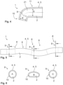
- Figure 5 shows an embodiment alternative of a sheath 4, 5 comprising a plurality of changes in direction 8 so that a meandering and/or almost meandering course of the bundle 2 through the sheath 4, 5 is achieved.
- the optic light guide 1, which is shown in figure 5 comprises a sheath 4, 5 having a cross-section 9 along its course that varies in shape.
- the cross-section 9 of the sheath 4, 5 refers at least to the cross-section of the guide channel 21 of the sheath 4, 5.
- Figure 6 shows three different cross-section shapes of the cross-sections 9 of the sheath 4, with the intersecting lines depicted in figure 5 and marked with the letters A, B and C showing in what position the sheath 4, 5 is intersected in each case.
- cross-sections A and C of the example are circular in shape, with cross-section B having an oval shape.
- a surface area of the respective cross-sectional area of the cross-section 9, A, B and C of the sheath 4, 5 can remain the same regardless of the shape of the cross-section 9. If the cross-sectional area does remain the same, then the amount of light that can be guided is not negatively influenced by a change in the shape of the cross-section of the bundle 2.
- the varying shape of the cross-section can be used to make optimal use of the available installation space. For example, in narrow points a non-circular shape can be used to avoid having to make an outer diameter of the optic light guide 1 in this spot smaller.
- An interspace between the single fibres 3 of the bundle 2 can be filled at least partially with an adhesive in the area enclosed by the sheath 4, 5.
- Said adhesive can be a chemically hardenable adhesive, for example. This makes it easier to stabilise the single fibres 3 at least in the area of the sheath 4, 5. This adhesive can also help to fix the bundle of fibres to the sheath 4, 5.
- the cross-section 9 of the guide channel 21 of the sheath 4, 5 can narrow along its course, as shown in figure 4 , for example.
- At least one end area 10 of the sheath 4, 5 may comprise a cross-sectional area that is smaller than an area located at a distance from this end area 10.
- the area located at a distance can be a central area 11 of the sheath 4, 5, for example.
- a front face defining the field of view of the endoscope tip 18 is formed (see figure 3 ).
- the front face in each case comprises a cover glass 22 covering the bundle 2 towards the outside that is arranged in a light exit area 23 of the bundle 2.
- the cover glass 22 allows hermetic sealing, for example, to prevent moisture from entering.
- the invention may provide for the end faces of the single fibres 3 of the bundle to be subjected to polishing if they are not polished already. This step can be performed prior to mounting the cover glass 22 in the light exit area 23, for example.
- the advantage of using a ceramic sheath 4, 5 is that said ceramic sheath has greater firmness and thermal resistance, which means that the end faces of the single fibres 3 can still be polished or abraded after the single fibres 3 have been enclosed by the sheath 4, 5.
- sheath 4, 5 itself can be revised, e.g. abraded and/or polished, more easily in a finishing step.
- the invention thus relates in particular to an optic light guide 1, 19, 20 with a plurality of light-guiding single fibres 3 which are combined into a bundle 2 and at least one sheath 4, 5 which encloses at least one section of an outer circumference of the bundle, the at least one sheath 4, 5 being made of ceramic.
Landscapes
- Physics & Mathematics (AREA)
- Health & Medical Sciences (AREA)
- Life Sciences & Earth Sciences (AREA)
- Optics & Photonics (AREA)
- Surgery (AREA)
- Engineering & Computer Science (AREA)
- General Physics & Mathematics (AREA)
- Heart & Thoracic Surgery (AREA)
- General Health & Medical Sciences (AREA)
- Pathology (AREA)
- Nuclear Medicine, Radiotherapy & Molecular Imaging (AREA)
- Biomedical Technology (AREA)
- Biophysics (AREA)
- Medical Informatics (AREA)
- Molecular Biology (AREA)
- Animal Behavior & Ethology (AREA)
- Radiology & Medical Imaging (AREA)
- Public Health (AREA)
- Veterinary Medicine (AREA)
- Manufacturing & Machinery (AREA)
- Astronomy & Astrophysics (AREA)
- Endoscopes (AREA)
- Instruments For Viewing The Inside Of Hollow Bodies (AREA)
- Optical Fibers, Optical Fiber Cores, And Optical Fiber Bundles (AREA)
Priority Applications (1)
| Application Number | Priority Date | Filing Date | Title |
|---|---|---|---|
| EP24152947.8A EP4332647A3 (de) | 2019-07-04 | 2019-07-04 | Optischer lichtleiter, endoskop, verfahren zur herstellung und verwendung eines optischen lichtleiters |
Applications Claiming Priority (2)
| Application Number | Priority Date | Filing Date | Title |
|---|---|---|---|
| EP24152947.8A EP4332647A3 (de) | 2019-07-04 | 2019-07-04 | Optischer lichtleiter, endoskop, verfahren zur herstellung und verwendung eines optischen lichtleiters |
| EP19184544.5A EP3760099B1 (de) | 2019-07-04 | 2019-07-04 | Optischer lichtleiter, endoskop, verfahren zur herstellung und verwendung eines optischen lichtleiters |
Related Parent Applications (2)
| Application Number | Title | Priority Date | Filing Date |
|---|---|---|---|
| EP19184544.5A Division EP3760099B1 (de) | 2019-07-04 | 2019-07-04 | Optischer lichtleiter, endoskop, verfahren zur herstellung und verwendung eines optischen lichtleiters |
| EP19184544.5A Division-Into EP3760099B1 (de) | 2019-07-04 | 2019-07-04 | Optischer lichtleiter, endoskop, verfahren zur herstellung und verwendung eines optischen lichtleiters |
Publications (2)
| Publication Number | Publication Date |
|---|---|
| EP4332647A2 true EP4332647A2 (de) | 2024-03-06 |
| EP4332647A3 EP4332647A3 (de) | 2024-05-22 |
Family
ID=67184806
Family Applications (2)
| Application Number | Title | Priority Date | Filing Date |
|---|---|---|---|
| EP24152947.8A Pending EP4332647A3 (de) | 2019-07-04 | 2019-07-04 | Optischer lichtleiter, endoskop, verfahren zur herstellung und verwendung eines optischen lichtleiters |
| EP19184544.5A Active EP3760099B1 (de) | 2019-07-04 | 2019-07-04 | Optischer lichtleiter, endoskop, verfahren zur herstellung und verwendung eines optischen lichtleiters |
Family Applications After (1)
| Application Number | Title | Priority Date | Filing Date |
|---|---|---|---|
| EP19184544.5A Active EP3760099B1 (de) | 2019-07-04 | 2019-07-04 | Optischer lichtleiter, endoskop, verfahren zur herstellung und verwendung eines optischen lichtleiters |
Country Status (4)
| Country | Link |
|---|---|
| US (1) | US12527466B2 (de) |
| EP (2) | EP4332647A3 (de) |
| CN (1) | CN114072042B (de) |
| WO (1) | WO2021003345A1 (de) |
Families Citing this family (1)
| Publication number | Priority date | Publication date | Assignee | Title |
|---|---|---|---|---|
| CN115177204A (zh) * | 2022-06-30 | 2022-10-14 | 上海树突精密仪器有限公司 | 一种集成导光束的高分辨率内窥镜 |
Family Cites Families (22)
| Publication number | Priority date | Publication date | Assignee | Title |
|---|---|---|---|---|
| GB1356474A (en) * | 1971-11-09 | 1974-06-12 | Barr & Stroud Ltd | Fibre-optic lightguides |
| JPS4932490A (de) * | 1972-07-24 | 1974-03-25 | ||
| JPS5812642A (ja) * | 1981-07-16 | 1983-01-24 | オリンパス光学工業株式会社 | 硬性内視鏡 |
| US4733937A (en) * | 1986-10-17 | 1988-03-29 | Welch Allyn, Inc. | Illuminating system for endoscope or borescope |
| JP2593560B2 (ja) * | 1988-12-26 | 1997-03-26 | オリンパス光学工業株式会社 | 内視鏡 |
| US20050234436A1 (en) * | 1999-07-14 | 2005-10-20 | Cardiofocus, Inc. | Methods of cardiac ablation in the vicinity of the right inferior pulmonary vein |
| US20020077550A1 (en) * | 1999-10-05 | 2002-06-20 | Rabiner Robert A. | Apparatus and method for treating gynecological diseases using an ultrasonic medical device operating in a transverse mode |
| US6385371B1 (en) * | 2000-04-03 | 2002-05-07 | Cogent Light Technologies, Inc. | Optical system including coupling for transmitting light between a single fiber light guide and multiple single fiber light guides |
| US6840909B2 (en) | 2002-03-25 | 2005-01-11 | Acueity, Inc. | Apparatus and method for intraductal cytology |
| DE10240508A1 (de) * | 2002-09-03 | 2004-03-11 | Schott Glas | Verfahren zur Herstellung eines Geätzten Optischen Faserbündels sowie verbessertes Geätztes Optisches Faserbündel |
| US7510524B2 (en) * | 2005-04-04 | 2009-03-31 | Invuity, Inc. | Optical waveguide sheath |
| US7824330B2 (en) * | 2005-11-28 | 2010-11-02 | Karl Storz Endovision, Inc. | Ceramic fiber optic taper housing for medical devices |
| US20080021276A1 (en) * | 2006-07-21 | 2008-01-24 | Oncoscope, Inc. | Protective probe tip, particularly for use on a fiber-optic probe used in an endoscopic application |
| CN100422775C (zh) * | 2006-09-29 | 2008-10-01 | 上海智源光电子有限公司 | 多光纤端口平台 |
| US20100041952A1 (en) | 2008-08-12 | 2010-02-18 | Omnimed Enterprises LLC | Medical Instrument Light Source Connection Device |
| JP5305946B2 (ja) * | 2009-01-27 | 2013-10-02 | 富士フイルム株式会社 | ライトガイド及び光源装置並びに内視鏡システム |
| EP2568869A1 (de) * | 2010-05-10 | 2013-03-20 | Nanamed, LLC | Verfahren und endoskopische vorrichtung zur untersuchung oder abbildung der innenfläche eines hohlraums im körper |
| WO2013133341A1 (ja) * | 2012-03-07 | 2013-09-12 | オリンパス株式会社 | 光学測定装置 |
| CA2890707A1 (en) * | 2012-11-07 | 2014-05-15 | 3Nt Medical Ltd. | Paranasal sinus access system |
| CA2900167C (en) * | 2013-03-11 | 2020-02-25 | Lightlab Imaging, Inc. | Optical fiber beam directing systems and apparatuses |
| US20150087911A1 (en) * | 2013-09-26 | 2015-03-26 | Gyrus Acmi, Inc. D.B.A Olympus Surgical Technologies America | Endoscope sheath deflection devices |
| JP2021097720A (ja) * | 2018-03-20 | 2021-07-01 | ソニーグループ株式会社 | 内視鏡及びアームシステム |
-
2019
- 2019-07-04 EP EP24152947.8A patent/EP4332647A3/de active Pending
- 2019-07-04 EP EP19184544.5A patent/EP3760099B1/de active Active
-
2020
- 2020-07-02 CN CN202080048957.7A patent/CN114072042B/zh active Active
- 2020-07-02 WO PCT/US2020/040623 patent/WO2021003345A1/en not_active Ceased
- 2020-07-02 US US17/624,004 patent/US12527466B2/en active Active
Also Published As
| Publication number | Publication date |
|---|---|
| EP3760099A1 (de) | 2021-01-06 |
| EP4332647A3 (de) | 2024-05-22 |
| US20220287555A1 (en) | 2022-09-15 |
| CN114072042B (zh) | 2026-03-10 |
| EP3760099B1 (de) | 2024-02-28 |
| WO2021003345A1 (en) | 2021-01-07 |
| US12527466B2 (en) | 2026-01-20 |
| CN114072042A (zh) | 2022-02-18 |
Similar Documents
| Publication | Publication Date | Title |
|---|---|---|
| US5391146A (en) | Mechanism for manipulating the distal end of a biomedical device | |
| US4745908A (en) | Inspection instrument fexible shaft having deflection compensation means | |
| US4267828A (en) | Endoscope having an extension guide for observation | |
| US4813400A (en) | Optical fiber assembly for an endoscope | |
| US4807597A (en) | Fiberscope | |
| US7510339B2 (en) | System for splicing fiber drop cables | |
| US12527466B2 (en) | Optic light guide, endoscope, method for producing and using an optic light guide | |
| US6878108B2 (en) | Insertion unit for endoscope | |
| EP4142566B1 (de) | Gelenkiger biegeabschnittskörper für ein einführendoskop | |
| JP2000121962A (ja) | 内視鏡 | |
| JPS61118713A (ja) | 内視鏡 | |
| CN121971021A (en) | Optical light guide, endoscope, method of making and using the same | |
| JP4017734B2 (ja) | 内視鏡の挿入部 | |
| US4796604A (en) | Endoscope and a light guide thereof and a method for manufacturing the light guide | |
| US6786648B2 (en) | Optical fiber coupling unit and optical waveguide arrangement, and method of producing an optical fiber coupling unit | |
| CN219070210U (zh) | 一种一体式蛇骨及内窥镜 | |
| KR20000077174A (ko) | 광 안내 유닛, 상기 유닛을 성형하기 위한 방법, 및 상기유닛을 구비한 치과용 핸드피스 | |
| CA1275589C (en) | Fiber-optic image-carrying device | |
| JPH03277343A (ja) | 内視鏡用温度分布測定装置 | |
| JP2610318B2 (ja) | 内視鏡 | |
| JP3494678B2 (ja) | 細径内視鏡 | |
| JP3710610B2 (ja) | ファイバスコープおよびその製造方法 | |
| RU143786U1 (ru) | Компактное устройство разветвления волокон оптического кабеля | |
| JP2001343538A (ja) | 光ファイババンドルの製造方法及び挿入治具 | |
| JPH05113541A (ja) | 内視鏡照明装置 |
Legal Events
| Date | Code | Title | Description |
|---|---|---|---|
| PUAI | Public reference made under article 153(3) epc to a published international application that has entered the european phase |
Free format text: ORIGINAL CODE: 0009012 |
|
| STAA | Information on the status of an ep patent application or granted ep patent |
Free format text: STATUS: THE APPLICATION HAS BEEN PUBLISHED |
|
| AC | Divisional application: reference to earlier application |
Ref document number: 3760099 Country of ref document: EP Kind code of ref document: P |
|
| AK | Designated contracting states |
Kind code of ref document: A2 Designated state(s): AL AT BE BG CH CY CZ DE DK EE ES FI FR GB GR HR HU IE IS IT LI LT LU LV MC MK MT NL NO PL PT RO RS SE SI SK SM TR |
|
| REG | Reference to a national code |
Ref country code: DE Ref legal event code: R079 Free format text: PREVIOUS MAIN CLASS: G02B0006240000 Ipc: A61B0001070000 |
|
| PUAL | Search report despatched |
Free format text: ORIGINAL CODE: 0009013 |
|
| AK | Designated contracting states |
Kind code of ref document: A3 Designated state(s): AL AT BE BG CH CY CZ DE DK EE ES FI FR GB GR HR HU IE IS IT LI LT LU LV MC MK MT NL NO PL PT RO RS SE SI SK SM TR |
|
| RIC1 | Information provided on ipc code assigned before grant |
Ipc: G02B 6/24 20060101ALI20240417BHEP Ipc: G02B 6/40 20060101ALI20240417BHEP Ipc: A61B 1/00 20060101ALI20240417BHEP Ipc: A61B 1/07 20060101AFI20240417BHEP |
|
| STAA | Information on the status of an ep patent application or granted ep patent |
Free format text: STATUS: REQUEST FOR EXAMINATION WAS MADE |
|
| 17P | Request for examination filed |
Effective date: 20241121 |
|
| RBV | Designated contracting states (corrected) |
Designated state(s): AL AT BE BG CH CY CZ DE DK EE ES FI FR GB GR HR HU IE IS IT LI LT LU LV MC MK MT NL NO PL PT RO RS SE SI SK SM TR |
|
| STAA | Information on the status of an ep patent application or granted ep patent |
Free format text: STATUS: EXAMINATION IS IN PROGRESS |
|
| 17Q | First examination report despatched |
Effective date: 20260302 |