EP4332641A1 - Lens and lens module including lens - Google Patents
Lens and lens module including lens Download PDFInfo
- Publication number
- EP4332641A1 EP4332641A1 EP23188589.8A EP23188589A EP4332641A1 EP 4332641 A1 EP4332641 A1 EP 4332641A1 EP 23188589 A EP23188589 A EP 23188589A EP 4332641 A1 EP4332641 A1 EP 4332641A1
- Authority
- EP
- European Patent Office
- Prior art keywords
- lens
- coating layer
- sio
- refractive index
- layer
- Prior art date
- Legal status (The legal status is an assumption and is not a legal conclusion. Google has not performed a legal analysis and makes no representation as to the accuracy of the status listed.)
- Pending
Links
Images



Classifications
-
- G—PHYSICS
- G02—OPTICS
- G02B—OPTICAL ELEMENTS, SYSTEMS OR APPARATUS
- G02B1/00—Optical elements characterised by the material of which they are made; Optical coatings for optical elements
- G02B1/10—Optical coatings produced by application to, or surface treatment of, optical elements
- G02B1/14—Protective coatings, e.g. hard coatings
-
- G—PHYSICS
- G02—OPTICS
- G02B—OPTICAL ELEMENTS, SYSTEMS OR APPARATUS
- G02B1/00—Optical elements characterised by the material of which they are made; Optical coatings for optical elements
- G02B1/04—Optical elements characterised by the material of which they are made; Optical coatings for optical elements made of organic materials, e.g. plastics
- G02B1/041—Lenses
-
- G—PHYSICS
- G02—OPTICS
- G02B—OPTICAL ELEMENTS, SYSTEMS OR APPARATUS
- G02B1/00—Optical elements characterised by the material of which they are made; Optical coatings for optical elements
- G02B1/10—Optical coatings produced by application to, or surface treatment of, optical elements
- G02B1/11—Anti-reflection coatings
- G02B1/113—Anti-reflection coatings using inorganic layer materials only
- G02B1/115—Multilayers
-
- G—PHYSICS
- G02—OPTICS
- G02B—OPTICAL ELEMENTS, SYSTEMS OR APPARATUS
- G02B1/00—Optical elements characterised by the material of which they are made; Optical coatings for optical elements
-
- G—PHYSICS
- G02—OPTICS
- G02B—OPTICAL ELEMENTS, SYSTEMS OR APPARATUS
- G02B13/00—Optical objectives specially designed for the purposes specified below
- G02B13/001—Miniaturised objectives for electronic devices, e.g. portable telephones, webcams, PDAs, small digital cameras
- G02B13/0015—Miniaturised objectives for electronic devices, e.g. portable telephones, webcams, PDAs, small digital cameras characterised by the lens design
- G02B13/002—Miniaturised objectives for electronic devices, e.g. portable telephones, webcams, PDAs, small digital cameras characterised by the lens design having at least one aspherical surface
- G02B13/0045—Miniaturised objectives for electronic devices, e.g. portable telephones, webcams, PDAs, small digital cameras characterised by the lens design having at least one aspherical surface having five or more lenses
-
- G—PHYSICS
- G02—OPTICS
- G02B—OPTICAL ELEMENTS, SYSTEMS OR APPARATUS
- G02B5/00—Optical elements other than lenses
- G02B5/20—Filters
- G02B5/208—Filters for use with infrared or ultraviolet radiation, e.g. for separating visible light from infrared and/or ultraviolet radiation
Definitions
- the present disclosure relates to a lens and a lens module including a lens.
- a camera module for monitoring may be installed in a building or a vehicle and may be configured to capture an image of the surrounding environment.
- a small-sized camera module may be installed on the front, rear, and side surfaces of a vehicle and may capture images of surrounding objects and vehicles in real time, thereby enabling safe driving and autonomous driving of a vehicle.
- a camera module may include a lens made of plastic to facilitate miniaturization and manufacturing.
- one or more lenses among a plurality of lenses included in a camera module may be made of plastic.
- a lens made of plastic may be easily deteriorated by sunlight, a camera module constantly exposed to the outside, such as a camera module for self-driving vehicles, may experience deterioration of resolution over time.
- a plastic lens may be easily yellowed by ultraviolet light, the resolution of a camera module including a plastic lens may decrease after a lens has been exposed to ultraviolet light for an elongated period of time.
- a lens in one general aspect, includes a lens unit having a refractive power; and a first coating layer and a second coating layer formed on either one or both of an object-side surface and an image-side surface of the lens unit in an optical axis direction of the lens unit, wherein a first refractive index of the first coating layer is greater than a second refractive index of the second coating layer.
- the first refractive index may be greater than a refractive index of the lens unit.
- the second refractive index may be smaller than a refractive index of the lens unit.
- the first refractive index may be in a range of 2.0 to 2.7.
- the second refractive index may be in a range of 1.01 to 1.50.
- the first coating layer may be made of a material including any one or any combination of any two or more of TiO 2 , Ti 3 O 5 , and Si 3 N 4 .
- the second coating layer may be made of a material including either one or both of SiO 2 and Al 2 O 3 .
- the first coating layer may include a plurality of coating layers made of TiO 2
- the second coating layer may include a plurality of coating layers made of SiO 2 .
- the first coating layer may include a plurality of coating layers made of Ti 3 O 5
- the second coating layer may include a plurality of coating layers made of SiO 2 .
- the first coating layer may include a plurality of coating layers made of Si 3 N 4
- the second coating layer may include a plurality of coating layers made of SiO 2 .
- the first coating layer may include a plurality of coating layers made of TiO 2
- the second coating layer may include a plurality of coating layers made of SiO 2 and a plurality of coating layers made Al 2 O 3 .
- the first coating layer may include a plurality of coating layers
- the second coating layer may include a plurality of coating layers alternately stacked with the coating layers of the first coating layer in the optical axis direction of the lens unit.
- the coating layers of the first coating layer may include coating layers having at least two different thicknesses
- the coating layers of the second coating layer may include coating layers having at least two different thicknesses
- a total number of the coating layers of the first coating layer and the coating layers of the second coating layer may be in a range of 10 to 30 coating layers.
- the first coating layer and the second coating layer may be alternately disposed in the optical axis direction of the lens unit.
- T1sum ⁇ T2sum may be satisfied, where T1sum is a total thickness of the first coating layer, and T2sum is a total thickness of the second coating layer.
- T1sum is a total thickness of the first coating layer
- T2sum is a total thickness of the second coating layer
- conditional expression 0.1900 ⁇ T1sum/(T1sum+T2sum) ⁇ 0.2100 may be satisfied, where T1sum is a total thickness of the first coating layer, and T2sum is a total thickness of the second coating layer.
- a lens module includes the lens described above.
- the lens module may further include a rear lens group disposed on an image side of the lens.
- the rear lens group may include one or more plastic lenses.
- the lens module may further include a front lens group disposed on an object side of the lens.
- the front lens group may include one or more glass lenses.
- first,” “second,” and “third” may be used herein to describe various members, components, regions, layers, or sections, these members, components, regions, layers, or sections are not to be limited by these terms. Rather, these terms are only used to distinguish one member, component, region, layer, or section from another member, component, region, layer, or section. Thus, a first member, component, region, layer, or section referred to in examples described herein may also be referred to as a second member, component, region, layer or section without departing from the teachings of the examples.
- spatially relative terms such as “above,” “upper,” “below,” and “lower” may be used herein for ease of description to describe one element's relationship to another element as shown in the figures. Such spatially relative terms are intended to encompass different orientations of the device in use or operation in addition to the orientation depicted in the figures. For example, if the device in the figures is turned over, an element described as being “above” or “upper” relative to another element will then be “below” or “lower” relative to the other element. Thus, the term “above” encompasses both the above and below orientations depending on the spatial orientation of the device.
- the device may also be oriented in other ways (for example, rotated by 90 degrees or at other orientations), and the spatially relative terms used herein are to be interpreted accordingly.
- the thickness, size, and shape of the lenses may be somewhat exaggerated for ease of description, and specifically, the shape of a spherical or non-spherical surface shown in the structural views is only presented as an example, but is not limited thereto.
- a lens according to a first embodiment may be configured to have a refractive power.
- a lens may include a lens unit having a refractive power.
- the lens unit may be configured to have a specific refractive power.
- a lens unit may have a positive or a negative refractive power.
- Either one or both of an object-side surface and an image-side surface of the lens unit may be convex or concave.
- the object-side surface of the lens unit may be convex.
- the image-side surface of the lens unit may be concave.
- the lens according to the first embodiment may be configured to block light of a specific wavelength.
- a lens according to an embodiment may be configured to block ultraviolet rays.
- the lens according to an embodiment may not be configured to block only ultraviolet rays.
- the lens according to an embodiment may be configured to block both ultraviolet rays and infrared rays.
- a lens according to an embodiment may include a first coating layer and a second coating layer. The first coating layer and the second coating layer may be formed on the lens unit and may be arranged in a predetermined order in the optical axis direction. For example, the first coating layer and the second coating layer may be alternately disposed in the optical axis direction.
- the first coating layer and the second coating layer may have different refractive indices.
- a refractive index of the first coating layer may be greater than a refractive index of the second coating layer.
- a refractive index of the first coating layer may be greater than a refractive index of the lens unit
- a refractive index of the second coating layer may be smaller than a refractive index of the lens unit.
- a lens according to a second embodiment may include a lens unit having a refractive power and a plurality of coating layers formed on the lens unit.
- the plurality of coating layers may include a first coating layer and a second coating layer having different thicknesses.
- a first average thickness of the first coating layer may be smaller than a second average thickness of the second coating layer.
- a first maximum thickness of the first coating layer may be smaller than a second maximum thickness of the second coating layer, and may be larger than a second minimum thickness of the second coating layer.
- a first total thickness of the first coating layer may be smaller than a second total thickness of the second coating layer.
- a lens according to a third embodiment may include a first coating layer and a second coating layer having different refractive indices.
- a refractive index of the first coating layer may be greater than a refractive index of the second coating layer.
- the first coating layer and the second coating layer may be alternately stacked on either one or both of an object-side surface and an image-side surface of the lens.
- the first coating layer and the second coating layer may be repeatedly formed on the object-side surface of the lens in the order of the first coating layer and the second coating layer.
- the thickness of the first coating layer may be smaller than the thickness of the nearest adjacent second coating layer.
- a thickness of the first coating layer formed on an object-side surface of the lens may be smaller than a thickness of the second coating layer formed immediately above the first coating layer.
- a thickness of the first coating layer formed between the second coating layers may be smaller than a thickness of the second coating layer formed closest to upper and lower portions of the first coating layer.
- a lens according to the fourth embodiment may include a first coating layer and a second coating layer having different refractive indices.
- a refractive index of the first coating layer may be 2.0 or more, and a refractive index of the second coating layer may be less than 1.5.
- a lens according to the fourth embodiment may be made of a material having a high refractive index.
- a lens according to the fourth embodiment may be made of a glass material.
- the lens module in an embodiment may include one or more lenses (hereinafter, referred to as coated lenses) according to the first to fourth embodiments.
- the lens module in an embodiment may include a coated lens according to the first embodiment.
- the lens module in an embodiment may include a coated lens according to the second embodiment.
- the lens module in an embodiment may include a coated lens according to the first embodiment and a coated lens according to the third embodiment.
- the lens module in an embodiment may include a plurality of lenses.
- the lens module in an embodiment may include a first lens, a second lens, a third lens, and a fourth lens sequentially disposed in ascending numerical order along an optical axis from an object side of the lens module toward an image side of the lens module.
- the first lens disposed nearest to an object may be a coated lens described in the first to fourth embodiments.
- a position of the coated lens in the first to fourth embodiments is not limited to the forwardmost lens (the first lens).
- the second lens disposed closest to the image side of the forwardmost lens (the first lens) may be a coated lens described in the first to fourth embodiments.
- a lens disposed closest to an object side or an image side of a stop may be a coated lens described in the first to fourth embodiments.
- the lens module in an embodiment may include a lens made of a glass material.
- the first lens disposed at the forwardmost side of the lens module may be a coated lens described in the first to fourth embodiments and may be made of a glass material.
- the second lens may be a coated lens described in the first to fourth embodiments and may be made of a glass material.
- the lens module in an embodiment may include a lens made of a plastic material to facilitate lightweightedness and miniaturization.
- a lens made of a plastic material to facilitate lightweightedness and miniaturization.
- one or more of the lenses arranged on an image side of the coated lens described in the first to fourth embodiments may be made of a plastic material.
- all of the lenses disposed on the image side of the coated lens described in the first to fourth embodiments may be made of a plastic material.
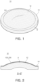
- FIG. 1 is a perspective diagram illustrating a lens according to an embodiment of the present disclosure.
- FIG. 2 is a cross-sectional diagram illustrating a lens illustrated in FIG. 1 taken along the line II-II' in FIG. 1 .
- FIG. 3 is an enlarged cross-sectional diagram illustrating portion A illustrated in FIG. 2 .
- a lens 10 in an embodiment may be configured to have a refractive power.
- the lens 10 may have a positive refractive power or a negative refractive power.
- the lens 10 may include a lens unit 12 and a flange portion 14.
- the lens unit 12 may be a region having a refractive power and transmitting effective light around an optical axis of the lens 10, and the flange portion 14 may be a region formed around the lens unit 12 and configured to not transmit effective light.
- the lens 10 may be made of a material resistant against external impacts and temperature changes.
- the lens 10 may be made of a glass material having a high refractive index and a high Abbe number.
- the lens 10 may be configured to block or reflect light of a specific wavelength.
- the lens 10 may be configured to block ultraviolet rays.
- the lens 10 may include a component for blocking ultraviolet rays.
- the lens 10 may include a first coating layer 100 and a second coating layer 200.
- the first coating layer 100 and the second coating layer 200 may be formed on either one of both of an object-side surface and an image-side surface of the lens 10.
- the first coating layer 100 and the second coating layer 200 may be formed on both of an object-side surface and an image-side surface of the lens unit 12.
- the first coating layer 100 and the second coating layer 200 may be formed on either an object-side surface or an image-side surface of the lens unit 12.
- the first coating layer 100 and the second coating layer 200 may be sequentially (or alternately) formed in one direction and may include 10 to 30 coating layers formed on one surface of the lens 10.
- a first coating layer 101, a second coating layer 201, a first coating layer 102, a second coating layer 202, a first coating layer 103, a second coating layer 203,. . . , a first coating layer 113, a second coating layer 213, a first coating layer 114, a second coating layer 214, a first coating layer 115, and a second coating layer 215 for a total of 30 coating layers may be formed on the object-side surface of the lens unit 12.
- the first coating layer 100 and the second coating layer 200 may be configured to have different refractive indices.
- a refractive index of the first coating layer 100 may be 2.0 or more, and a refractive index of the second coating layer 200 may be 1.5 or less.
- a refractive index of the first coating layer 100 may be 2.0 to 2.7, and a refractive index of the second coating layer 200 may be 1.01 to 1.50.
- a refractive index of the first coating layer 100 may be greater than a refractive index of the lens 10 or lens unit 12, and a refractive index of the second coating layer 200 may be greater than a refractive index of the lens 10 or lens unit 12.
- the first coating layer 100 and the second coating layer 200 may be configured to have different Abbe numbers.
- an Abbe number of the first coating layer 100 may be less than 40, and an Abbe number of the second coating layer 200 may be 50 or more.
- an Abbe number of the first coating layer 100 may be less than 20, and an Abbe number of the second coating layer 200 may be 70 or more.
- first coating layer 100 and the second coating layer 200 may be made of a single material or a plurality of materials.
- the first coating layer 100 may be made of a single material including only one of TiO 2 , Ti 3 O 5 , and Si 3 N 4 , or a plurality of materials including any combination of any two or more of TiO 2 , Ti 3 O 5 , and Si 3 N 4 .
- the second coating layer 200 may be made of a single material including only one of SiO 2 and Al 2 O 3 , or a plurality of materials including SiO 2 and Al 2 O 3 .
- the first coating layer 100 may be made of a single material including only TiO 2
- the second coating layer 200 may be made of a single material including only SiO 2 (see Table 2 below).
- the first coating layer 100 may be made of a single material including only Ti 3 O 5
- the second coating layer 200 may be made of a single material including only SiO 2 (see Table 3 below).
- the first coating layer 100 may be made of a single material including only Si 3 N 4
- the second coating layer 200 may be made of a single material including only SiO 2 (see Table 4 below).
- the first coating layer 100 may be made of a single material including only TiO 2
- the second coating layer 200 may be made of a plurality of materials including SiO 2 and Al 2 O 3 (see Table 5 below).
- Table 1 below illustrates refractive indices and Abbe numbers of materials that may be included in the first coating layer 100 and the second coating layer 200.
- Table 1 Material Refractive Index Abbe Number nd nF nC 587.6 nm 486.134 nm 656.281 nm TiO 2 (bulk) 2.614 2.735 2.571 9.84 TiO 2 (film) 2.146 2.209 2.123 13.36 SiO 2 (film) 1.473 1.478 1.472 73.97 Al 2 O 3 (film) 1.68 1.688 1.676 57.14 Si 3 N 4 (film) 2.025 2.045 2.016 36.08 Ti 3 O 5 (film) 2.467 2.583 2.425 9.28
- nd, nF, and nC are the refractive indices of the material at the wavelengths of the Fraunhofer d, F, and C spectral lines (587.6 nm, 486.134 nm, and 656.281 nm, respectively).
- Tables 2 to 5 below are examples of coating layers formed on one surface of lens 10.
- the odd-numbered layers (1, 3, 5, ...) are the first coating layer 100
- the even-numbered layers (2, 4, 8, ...) are the second coating layer 200
- the layers 1, 3, 5, 9, 11, and 14 are the first coating layer 100
- the layers 2, 4, 6, 7, 8, 10, 12, 13, 15 and 16 are the second coating layer 200.
- the total number of layers in the first coating layer 100 and the second coating layer 200 are 16 to 22 layers, but the total number of layers in the first coating layer 100 and the second coating layer 200 is not limited to 16 to 22 layers.
- the total number of layers in the first coating layer 100 and the second coating layer 200 may be from 10 to 30 layers.
- the first coating layer 100 and the second coating layer 200 may be formed to have different thicknesses.
- a thickness of the first coating layer 100 may be smaller than a thickness of the second coating layer 200.
- a total thickness T1sum of all of the layers of the first coating layer 100 formed on one surface of the lens 10 and a total thickness T2sum of all of the layers of the second coating layer 200 formed on the same surface of the lens 10 may satisfy any one or any combination of any two or more of the conditional expressions below T 1 sum ⁇ T 2 sum 0.2000 ⁇ T 1 sum / T 2 sum ⁇ 0.3000 0.1900 ⁇ T 1 sum/ T 1 sum + T 2 sum ⁇ 0.2100
- Table 6 illustrates a distribution of thicknesses of the layers of the first coating layer 100 and the layers of the second coating layer 200 formed on one surface of the lens 10.
- Table 6 Layer Material Example 1 Thickness (nm) Example 2 Thickness (nm) Example 3 Thickness (nm) 18 SiO 2 105 101 97 17 TiO 2 43 46 41 16 SiO 2 33 32 32 15 TiO 2 30 29 28 14 SiO 2 103 99 98 13 TiO 2 15 13 16 12 SiO 2 79 79 75 11 TiO 2 24 23 22 10 SiO 2 97 95 93 9 TiO 2 15 16 15 8 SiO 2 98 96 90 7 TiO 2 20 18 21 6 SiO 2 88 86 83 5 TiO 2 15 13 12 4 SiO 2 109 101 99 3 TiO 2 20 16 19 2 SiO 2 53 52 49 1 TiO 2 12 16 12 Base Glass - - - -
- Table 7 shows the values of T1sum, T2sum, T1sum+T2sum, T1sum/T2sum, and T1sum/(T1sum+T2sum) in Examples 1-3 in Table 6.
- Table 7 Example 1 2 3 T1sum 194 190 186 T2sum 765 741 716 T1sum+T2sum 959 931 902 T1sum/T2sum 0.2536 0.2564 0.2598 T1sum/(T1sum+T2sum) 0.2023 0.2041 0.2062
- the layers of the first coating layer 100 and the layers of the second coating layer 200 may be formed to have different thicknesses as illustrated in Examples 1 to 3 in Table 6.
- a thickness of the layer of the first coating layer 100 forming the first layer and a thickness of the layer of the first coating layer 100 forming the third layer may be different from each other
- a thickness of the layer of the second coating layer 100 forming the second layer and a thickness of the layer of the second coating layer 100 forming the fourth layer may be different from each other.
- the layers of the first coating layer 100 forming the first layer, the third layer, the fifth layer, and the seventh layer may be formed to have different thicknesses.
- the layers of the second coating layer 200 forming the second layer, the fourth layer, the sixth layer, the eighth layer, the tenth layer, the twelfth layer, the fourteenth layer, the sixteenth layer, and the eighteenth layer may be formed to have different thicknesses.
- the layers of the first coating layer 100 and the second coating layer 200 may be formed to have different thicknesses.
- the layers of the first coating layer 100 forming the first layer and the fifth layer may be formed to have the same thickness (see Example 3 in Table 6), or the layers of the first coating layer 100 forming the first layer, the third layer, and the ninth layer may be formed to have the same thickness (see Example 2 in Table 6).
- an antireflection layer may be formed on either one or both of the object-side surface and the image-side surface of the lens 10.
- an antireflection layer may be formed on the second coating layer 200.
- the lens 10 configured as described above may block light (e.g., ultraviolet rays) of a specific wavelength that may impair resolution, degrade the plastic lens, or significantly reduce the amount of incident light.
- light e.g., ultraviolet rays
- a lens module including a lens (hereinafter, referred to as a coated lens) according to the above-described embodiment will now be described.
- FIG. 4 is a diagram illustrating a lens module according to an embodiment of the present disclosure.
- a lens module 20 may include a lens barrel 30 and lenses L1, L2, L3, L4, L5, L6, and L7.
- the components of the lens module 20 are not limited to the lens barrel 30 and the lenses L1, L2, L3, L4, L5, L6, and L7.
- the lens module 20 may further include spacers disposed between the lenses L1, L2, L3, L4, L5, L6, and L7 to maintain predetermined spacings between the lenses L1, L2, L3, L4, L5, L6, and L7.
- the lens module 20 may further include one or more stops disposed in the lens barrel 30.
- the lens barrel 30 may be configured to accommodate one or more of the lenses L1, L2, L3, L4, L5, L6, and L7.
- the lens barrel 30 may be configured to accommodate all of the lenses L1, L2, L3, L4, L5, L6, and L7 sequentially disposed in ascending numerical order along an optical axis of the lens module 20 from an object side of the lens module 20 toward an image side of the lens module 20.
- the lens barrel 30 may include a plurality of barrel members.
- the lens barrel 30 may include a first barrel member 32 configured to accommodate the first lens L1, and a second barrel member 34 configured to accommodate the second lens L2 to the seventh lens L7.
- the first barrel member 32 and the second barrel member 34 may be firmly coupled to each other by an interference fit or screw fastening.
- Each of the lenses L1, L2, L3, L4, L5, L6, and L7 may be configured to have a refractive power.
- the first lens L1, the second lens L2, and the sixth lens L6 may be configured to have a negative refractive power
- the third lens L3 to the fifth lens L5 and the seventh lens L7 may be configured to have a positive refractive power.
- the lens module 20 may include one or more coated lenses 10 described above with reference to FIGS. 1 to 3 .
- the first lens L1 disposed at the forwardmost side of the lens module 20 may be the coated lens 10 described above with reference to FIGS. 1 to 3 .
- the lens module 20 may include one or more glass lenses and one or more plastic lenses.
- the first lens L1 disposed at the forwardmost side of the lens module may be made of a glass material
- the second lens L2 to the seventh lens L7 may be made of a plastic material.
- the lens module 20 since ultraviolet rays are blocked by the first lens L1 disposed at the forwardmost side of the lens module 20 configured as described above, deterioration of the second lens L2 to the seventh lens L7 made of a plastic material may be significantly reduced. Also, in the lens module 20 according to the embodiment, since external radiant heat is substantially blocked by the coated lens 10 constituting the first lens L1, deformation of the plastic lenses L2, L3, L4, L5, L6, and L7 and changes in optical characteristics of the plastic lenses L2, L3, L4, L5, L6, and L7 due to heat may be reduced. Accordingly, the lens module 20 according to the embodiment may achieve a high resolution even under adverse conditions.
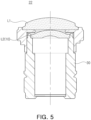
- FIG. 5 is a diagram illustrating a lens module according to another embodiment of the present disclosure.
- a lens module 22 may include a lens barrel 30 and lenses L1 and L2.
- the components of the lens module 22 are not limited to the lens barrel 30 and the lenses L1 and L2.
- the lens module 22 may further include a spacer disposed between the lenses L1 and L2 to maintain a predetermined spacing between the lenses L1 and L2.
- the lens module 22 may further include one or more stops disposed in the lens barrel 30.
- the lens barrel 30 may be configured to accommodate one or more of the lenses L1 and L2.
- the lens barrel 30 may be configured to accommodate the first lens L1 and the second lens L2 sequentially disposed in ascending numerical order along an optical axis of the lens module 22 from an object side of the lens module 22 toward an image side of the lens module 22.
- the lens module 22 may include one or more coated lenses 10 described above with reference to FIGS. 1 to 3 .
- the second lens L2 may be the coated lens 10 described above with reference to FIGS. 1 to 3 .
- the lens module 22 may include one or more glass lenses.
- both the first lens L1 and the second lens L2 may be made of a glass material.
- FIG. 6 is a diagram illustrating a lens module according to another embodiment of the present disclosure.
- a lens module 24 may include a lens barrel 30 and a plurality of lenses L1, L2, L3, L4, L5, L6, and L7.
- the components of the lens module 24 are not limited to the lens barrel 30 and the lenses L1, L2, L3, L4, L5, L6, and L7.
- the lens module 24 may further include spacers disposed between the lenses L1, L2, L3, L4, L5, L6, and L7 to maintain predetermined spacings between the lenses L1, L2, L3, L4, L5, L6, and L7.
- the lens module 24 may further include one or more stops disposed in the lens barrel 30.
- the lens barrel 30 may be configured to accommodate one or more lenses L1, L2, L3, L4, L5, L6, and L7.
- the lens barrel 30 may be configured to accommodate all of the lenses L1, L2, L3, L4, L5, L6, and L7 sequentially disposed in ascending numerical order along an optical axis of the lens module 24 from an object side of the lens module 24 toward an image side of the lens module 24.
- the lens barrel 30 may include a plurality of barrel members.
- the lens barrel 30 may include a first barrel member 32 configured to accommodate the first lens L1 and a second barrel member 34 configured to accommodate the second lens L2 to the seventh lens L7.
- the first barrel member 32 and the second barrel member 34 may be firmly coupled to each other by an interference fit or screw fastening.
- the lens module 24 may include one or more coated lenses 10 described above with reference to FIGS. 1 to 3 .
- the second lens L2 of the first lens L1 to the seventh lens L7 may be the coated lens 10 described above with reference to FIGS. 1 to 3 .
- the lens module 24 may include one or more glass lenses and one or more plastic lenses.
- the first lens L1 and the second lens L2 may be made of a glass material
- the third lens L3 to the seventh lens L7 may be made of a plastic material.
- the lens module 24 since ultraviolet rays may be blocked by the second lens L2 disposed in the lens module 24 configured as described above, deterioration of the third lens L3 to the seventh lens L7 made of a plastic material may be significantly reduced. Also, in the lens module 24 according to the embodiment, since the first lens L1 is disposed on the object side of the second lens constituted by the coated lens 10, the first coating layer 100 and the second coating layer 200 of the coated lens 10 may be prevented from being damaged or detached due to external impacts.
- a lens in an embodiment may reduce deterioration caused by ultraviolet rays.
- the lens module in an embodiment may include one or more plastic lenses protected from deterioration, the number of glass lenses, which may be expensive and difficult to manufacture, may be significantly reduced.
Landscapes
- Physics & Mathematics (AREA)
- General Physics & Mathematics (AREA)
- Optics & Photonics (AREA)
- Chemical & Material Sciences (AREA)
- Inorganic Chemistry (AREA)
- Lenses (AREA)
Abstract
Description
- This application claims benefit of
Korean Patent Application Nos. 10-2022-0110190 filed on August 31, 2022 10-2023-0052586 filed on April 21, 2023, in the Korean - The present disclosure relates to a lens and a lens module including a lens.
- A camera module for monitoring may be installed in a building or a vehicle and may be configured to capture an image of the surrounding environment. For example, a small-sized camera module may be installed on the front, rear, and side surfaces of a vehicle and may capture images of surrounding objects and vehicles in real time, thereby enabling safe driving and autonomous driving of a vehicle.
- A camera module may include a lens made of plastic to facilitate miniaturization and manufacturing. For example, one or more lenses among a plurality of lenses included in a camera module may be made of plastic. However, since a lens made of plastic may be easily deteriorated by sunlight, a camera module constantly exposed to the outside, such as a camera module for self-driving vehicles, may experience deterioration of resolution over time. As a specific example, since a plastic lens may be easily yellowed by ultraviolet light, the resolution of a camera module including a plastic lens may decrease after a lens has been exposed to ultraviolet light for an elongated period of time.
- This Summary is provided to introduce a selection of concepts in simplified form that are further described below in the Detailed Description. This Summary is not intended to identify key features or essential features of the claimed subject matter, nor is it intended to be used as an aid in determining the scope of the claimed subject matter.
- In one general aspect, a lens includes a lens unit having a refractive power; and a first coating layer and a second coating layer formed on either one or both of an object-side surface and an image-side surface of the lens unit in an optical axis direction of the lens unit, wherein a first refractive index of the first coating layer is greater than a second refractive index of the second coating layer.
- The first refractive index may be greater than a refractive index of the lens unit.
- The second refractive index may be smaller than a refractive index of the lens unit.
- The first refractive index may be in a range of 2.0 to 2.7.
- The second refractive index may be in a range of 1.01 to 1.50.
- The first coating layer may be made of a material including any one or any combination of any two or more of TiO2, Ti3O5, and Si3N4.
- The second coating layer may be made of a material including either one or both of SiO2 and Al2O3.
- The first coating layer may include a plurality of coating layers made of TiO2, and the second coating layer may include a plurality of coating layers made of SiO2.
- The first coating layer may include a plurality of coating layers made of Ti3O5, and the second coating layer may include a plurality of coating layers made of SiO2.
- The first coating layer may include a plurality of coating layers made of Si3N4, and the second coating layer may include a plurality of coating layers made of SiO2.
- The first coating layer may include a plurality of coating layers made of TiO2, and the second coating layer may include a plurality of coating layers made of SiO2 and a plurality of coating layers made Al2O3.
- The first coating layer may include a plurality of coating layers, and the second coating layer may include a plurality of coating layers alternately stacked with the coating layers of the first coating layer in the optical axis direction of the lens unit.
- The coating layers of the first coating layer may include coating layers having at least two different thicknesses, and the coating layers of the second coating layer may include coating layers having at least two different thicknesses.
- A total number of the coating layers of the first coating layer and the coating layers of the second coating layer may be in a range of 10 to 30 coating layers.
- The first coating layer and the second coating layer may be alternately disposed in the optical axis direction of the lens unit.
- The conditional expression T1sum < T2sum may be satisfied, where T1sum is a total thickness of the first coating layer, and T2sum is a total thickness of the second coating layer.
- The conditional expression 0.2000 ≤ T1sum/T2sum ≤ 0.3000 may be satisfied, where T1sum is a total thickness of the first coating layer, and T2sum is a total thickness of the second coating layer.
- The conditional expression 0.1900 < T1sum/(T1sum+T2sum) < 0.2100 may be satisfied, where T1sum is a total thickness of the first coating layer, and T2sum is a total thickness of the second coating layer.
- In another general aspect, a lens module includes the lens described above.
- The lens module may further include a rear lens group disposed on an image side of the lens.
- The rear lens group may include one or more plastic lenses.
- The lens module may further include a front lens group disposed on an object side of the lens.
- The front lens group may include one or more glass lenses.
- Other features and aspects will be apparent from the following detailed description, the drawings, and the claims.
-
-
FIG. 1 is a perspective diagram illustrating a lens according to an embodiment of the present disclosure. -
FIG. 2 is a cross-sectional diagram illustrating a lens illustrated inFIG. 1 taken along the line II-II' inFIG. 1 . -
FIG. 3 is an enlarged cross-sectional diagram illustrating portion A illustrated inFIG. 2 . -
FIG. 4 is a diagram illustrating a lens module according to an embodiment of the present disclosure. -
FIG. 5 is a diagram illustrating a lens module according to another embodiment of the present disclosure. -
FIG. 6 is a diagram illustrating a lens module according to another embodiment of the present disclosure. - Throughout the drawings and the detailed description, the same reference numerals refer to the same elements. The drawings may not be to scale, and the relative sizes, proportions, and depictions of elements in the drawings may be exaggerated for clarity, illustration, and convenience.
- The following detailed description is provided to assist the reader in gaining a comprehensive understanding of the methods, apparatuses, and/or systems described herein. However, various changes, modifications, and equivalents of the methods, apparatuses, and/or systems described herein will be apparent after an understanding of the disclosure of this application. For example, the sequences of operations described herein are merely examples, and are not limited to those set forth herein, but may be changed as will be apparent after an understanding of the disclosure of this application, with the exception of operations necessarily occurring in a certain order. Also, descriptions of features that are known in the art may be omitted for increased clarity and conciseness.
- The features described herein may be embodied in different forms, and are not to be construed as being limited to the examples described herein. Rather, the examples described herein have been provided merely to illustrate some of the many possible ways of implementing the methods, apparatuses, and/or systems described herein that will be apparent after an understanding of the disclosure of this application.
- Throughout the specification, when an element, such as a layer, region, or substrate, is described as being "on," "connected to," or "coupled to" another element, it may be directly "on," "connected to," or "coupled to" the other element, or there may be one or more other elements intervening therebetween. In contrast, when an element is described as being "directly on," "directly connected to," or "directly coupled to" another element, there can be no other elements intervening therebetween.
- As used herein, the term "and/or" includes any one and any combination of any two or more of the associated listed items.
- Although terms such as "first," "second," and "third" may be used herein to describe various members, components, regions, layers, or sections, these members, components, regions, layers, or sections are not to be limited by these terms. Rather, these terms are only used to distinguish one member, component, region, layer, or section from another member, component, region, layer, or section. Thus, a first member, component, region, layer, or section referred to in examples described herein may also be referred to as a second member, component, region, layer or section without departing from the teachings of the examples.
- Spatially relative terms such as "above," "upper," "below," and "lower" may be used herein for ease of description to describe one element's relationship to another element as shown in the figures. Such spatially relative terms are intended to encompass different orientations of the device in use or operation in addition to the orientation depicted in the figures. For example, if the device in the figures is turned over, an element described as being "above" or "upper" relative to another element will then be "below" or "lower" relative to the other element. Thus, the term "above" encompasses both the above and below orientations depending on the spatial orientation of the device. The device may also be oriented in other ways (for example, rotated by 90 degrees or at other orientations), and the spatially relative terms used herein are to be interpreted accordingly.
- The terminology used herein is for describing various examples only, and is not to be used to limit the disclosure. The articles "a," "an," and "the" are intended to include the plural forms as well, unless the context clearly indicates otherwise. The terms "comprises," "includes," and "has" specify the presence of stated features, numbers, operations, members, elements, and/or combinations thereof, but do not preclude the presence or addition of one or more other features, numbers, operations, members, elements, and/or combinations thereof.
- In the structural views of the optical imaging systems in the drawings, the thickness, size, and shape of the lenses may be somewhat exaggerated for ease of description, and specifically, the shape of a spherical or non-spherical surface shown in the structural views is only presented as an example, but is not limited thereto.
- A lens according to a first embodiment may be configured to have a refractive power. For example, a lens may include a lens unit having a refractive power. The lens unit may be configured to have a specific refractive power. For example, a lens unit may have a positive or a negative refractive power. Either one or both of an object-side surface and an image-side surface of the lens unit may be convex or concave. For example, the object-side surface of the lens unit may be convex. As another example, the image-side surface of the lens unit may be concave.
- The lens according to the first embodiment may be configured to block light of a specific wavelength. For example, a lens according to an embodiment may be configured to block ultraviolet rays. However, the lens according to an embodiment may not be configured to block only ultraviolet rays. For example, the lens according to an embodiment may be configured to block both ultraviolet rays and infrared rays. To this end, a lens according to an embodiment may include a first coating layer and a second coating layer. The first coating layer and the second coating layer may be formed on the lens unit and may be arranged in a predetermined order in the optical axis direction. For example, the first coating layer and the second coating layer may be alternately disposed in the optical axis direction.
- The first coating layer and the second coating layer may have different refractive indices. For example, a refractive index of the first coating layer may be greater than a refractive index of the second coating layer. As another example, a refractive index of the first coating layer may be greater than a refractive index of the lens unit, and a refractive index of the second coating layer may be smaller than a refractive index of the lens unit.
- A lens according to a second embodiment may include a lens unit having a refractive power and a plurality of coating layers formed on the lens unit. In the lens according to the second embodiment, the plurality of coating layers may include a first coating layer and a second coating layer having different thicknesses. For example, a first average thickness of the first coating layer may be smaller than a second average thickness of the second coating layer. As another example, a first maximum thickness of the first coating layer may be smaller than a second maximum thickness of the second coating layer, and may be larger than a second minimum thickness of the second coating layer. As another example, a first total thickness of the first coating layer may be smaller than a second total thickness of the second coating layer.
- A lens according to a third embodiment may include a first coating layer and a second coating layer having different refractive indices. In the lens according to the third embodiment, a refractive index of the first coating layer may be greater than a refractive index of the second coating layer. In the lens according to the third embodiment, the first coating layer and the second coating layer may be alternately stacked on either one or both of an object-side surface and an image-side surface of the lens. For example, the first coating layer and the second coating layer may be repeatedly formed on the object-side surface of the lens in the order of the first coating layer and the second coating layer. In the lens according to the third embodiment, the thickness of the first coating layer may be smaller than the thickness of the nearest adjacent second coating layer. For example, a thickness of the first coating layer formed on an object-side surface of the lens may be smaller than a thickness of the second coating layer formed immediately above the first coating layer. As another example, a thickness of the first coating layer formed between the second coating layers may be smaller than a thickness of the second coating layer formed closest to upper and lower portions of the first coating layer.
- A lens according to the fourth embodiment may include a first coating layer and a second coating layer having different refractive indices. For example, in the lens according to the fourth embodiment, a refractive index of the first coating layer may be 2.0 or more, and a refractive index of the second coating layer may be less than 1.5. A lens according to the fourth embodiment may be made of a material having a high refractive index. For example, a lens according to the fourth embodiment may be made of a glass material.
- The lens module in an embodiment may include one or more lenses (hereinafter, referred to as coated lenses) according to the first to fourth embodiments. For example, the lens module in an embodiment may include a coated lens according to the first embodiment. As another example, the lens module in an embodiment may include a coated lens according to the second embodiment. As another example, the lens module in an embodiment may include a coated lens according to the first embodiment and a coated lens according to the third embodiment.
- The lens module in an embodiment may include a plurality of lenses. For example, the lens module in an embodiment may include a first lens, a second lens, a third lens, and a fourth lens sequentially disposed in ascending numerical order along an optical axis from an object side of the lens module toward an image side of the lens module. Among the first lenses to fourth lenses, the first lens disposed nearest to an object (a forwardmost lens) may be a coated lens described in the first to fourth embodiments. However, a position of the coated lens in the first to fourth embodiments is not limited to the forwardmost lens (the first lens). For example, the second lens disposed closest to the image side of the forwardmost lens (the first lens) may be a coated lens described in the first to fourth embodiments. As another example, among the first lens to fourth lens, a lens disposed closest to an object side or an image side of a stop may be a coated lens described in the first to fourth embodiments.
- The lens module in an embodiment may include a lens made of a glass material. For example, among the first lens to fourth lenses sequentially disposed in ascending numerical order from the object side of the lens module toward the image side of the lens module, the first lens disposed at the forwardmost side of the lens module may be a coated lens described in the first to fourth embodiments and may be made of a glass material. As another example, the second lens may be a coated lens described in the first to fourth embodiments and may be made of a glass material.
- The lens module in an embodiment may include a lens made of a plastic material to facilitate lightweightedness and miniaturization. For example, one or more of the lenses arranged on an image side of the coated lens described in the first to fourth embodiments may be made of a plastic material. As another example, all of the lenses disposed on the image side of the coated lens described in the first to fourth embodiments may be made of a plastic material.
- Hereinafter, various embodiments will be described in greater detail with reference to the drawings.
-
FIG. 1 is a perspective diagram illustrating a lens according to an embodiment of the present disclosure.FIG. 2 is a cross-sectional diagram illustrating a lens illustrated inFIG. 1 taken along the line II-II' inFIG. 1 .FIG. 3 is an enlarged cross-sectional diagram illustrating portion A illustrated inFIG. 2 . - Referring to
FIG. 1 , alens 10 in an embodiment may be configured to have a refractive power. For example, thelens 10 may have a positive refractive power or a negative refractive power. Thelens 10 may include alens unit 12 and aflange portion 14. Thelens unit 12 may be a region having a refractive power and transmitting effective light around an optical axis of thelens 10, and theflange portion 14 may be a region formed around thelens unit 12 and configured to not transmit effective light. - The
lens 10 may be made of a material resistant against external impacts and temperature changes. For example, thelens 10 may be made of a glass material having a high refractive index and a high Abbe number. - The
lens 10 may be configured to block or reflect light of a specific wavelength. For example, thelens 10 may be configured to block ultraviolet rays. To this end, thelens 10 may include a component for blocking ultraviolet rays. For example, thelens 10 may include a first coating layer 100 and a second coating layer 200. - The first coating layer 100 and the second coating layer 200 may be formed on either one of both of an object-side surface and an image-side surface of the
lens 10. For example, the first coating layer 100 and the second coating layer 200 may be formed on both of an object-side surface and an image-side surface of thelens unit 12. As another example, the first coating layer 100 and the second coating layer 200 may be formed on either an object-side surface or an image-side surface of thelens unit 12. - The first coating layer 100 and the second coating layer 200 may be sequentially (or alternately) formed in one direction and may include 10 to 30 coating layers formed on one surface of the
lens 10. For example, as illustrated inFIG. 3 , afirst coating layer 101, asecond coating layer 201, afirst coating layer 102, asecond coating layer 202, afirst coating layer 103, asecond coating layer 203,. . . , afirst coating layer 113, asecond coating layer 213, afirst coating layer 114, asecond coating layer 214, afirst coating layer 115, and asecond coating layer 215 for a total of 30 coating layers may be formed on the object-side surface of thelens unit 12. - The first coating layer 100 and the second coating layer 200 may be configured to have different refractive indices. For example, a refractive index of the first coating layer 100 may be 2.0 or more, and a refractive index of the second coating layer 200 may be 1.5 or less. As another example, a refractive index of the first coating layer 100 may be 2.0 to 2.7, and a refractive index of the second coating layer 200 may be 1.01 to 1.50. As another example, a refractive index of the first coating layer 100 may be greater than a refractive index of the
lens 10 orlens unit 12, and a refractive index of the second coating layer 200 may be greater than a refractive index of thelens 10 orlens unit 12. - The first coating layer 100 and the second coating layer 200 may be configured to have different Abbe numbers. For example, an Abbe number of the first coating layer 100 may be less than 40, and an Abbe number of the second coating layer 200 may be 50 or more. Preferably, an Abbe number of the first coating layer 100 may be less than 20, and an Abbe number of the second coating layer 200 may be 70 or more.
- Each of the first coating layer 100 and the second coating layer 200 may be made of a single material or a plurality of materials. For example, the first coating layer 100 may be made of a single material including only one of TiO2, Ti3O5, and Si3N4, or a plurality of materials including any combination of any two or more of TiO2, Ti3O5, and Si3N4. As another example, the second coating layer 200 may be made of a single material including only one of SiO2 and Al2O3, or a plurality of materials including SiO2 and Al2O3.
- For example, the first coating layer 100 may be made of a single material including only TiO2, and the second coating layer 200 may be made of a single material including only SiO2 (see Table 2 below).
- As another example, the first coating layer 100 may be made of a single material including only Ti3O5, and the second coating layer 200 may be made of a single material including only SiO2 (see Table 3 below).
- As another example, the first coating layer 100 may be made of a single material including only Si3N4, and the second coating layer 200 may be made of a single material including only SiO2 (see Table 4 below).
- As another example, the first coating layer 100 may be made of a single material including only TiO2, and the second coating layer 200 may be made of a plurality of materials including SiO2 and Al2O3 (see Table 5 below).
- Table 1 below illustrates refractive indices and Abbe numbers of materials that may be included in the first coating layer 100 and the second coating layer 200.
Table 1 Material Refractive Index Abbe Number nd nF nC 587.6 nm 486.134 nm 656.281 nm TiO2 (bulk) 2.614 2.735 2.571 9.84 TiO2 (film) 2.146 2.209 2.123 13.36 SiO2 (film) 1.473 1.478 1.472 73.97 Al2O3 (film) 1.68 1.688 1.676 57.14 Si3N4 (film) 2.025 2.045 2.016 36.08 Ti3O5 (film) 2.467 2.583 2.425 9.28 - In Table 1, nd, nF, and nC are the refractive indices of the material at the wavelengths of the Fraunhofer d, F, and C spectral lines (587.6 nm, 486.134 nm, and 656.281 nm, respectively).
- Tables 2 to 5 below are examples of coating layers formed on one surface of
lens 10. - For reference, in Tables 2 to 4, the odd-numbered layers (1, 3, 5, ...) are the first coating layer 100, and the even-numbered layers (2, 4, 8, ...) are the second coating layer 200. In Table 5, the
layers 1, 3, 5, 9, 11, and 14 are the first coating layer 100, and thelayers - For reference, in Tables 2 to 5, the total number of layers in the first coating layer 100 and the second coating layer 200 are 16 to 22 layers, but the total number of layers in the first coating layer 100 and the second coating layer 200 is not limited to 16 to 22 layers. For example, the total number of layers in the first coating layer 100 and the second coating layer 200 may be from 10 to 30 layers.
Table 2 Layer Material 18 SiO2 17 TiO2 16 SiO2 15 TiO 214 SiO2 13 TiO 212 SiO2 11 TiO 210 SiO2 9 TiO2 8 SiO2 7 TiO2 6 SiO2 5 TiO2 4 SiO2 3 TiO2 2 SiO2 1 TiO2 Base Glass Table 3 Layer Material 22 SiO2 21 Ti3O5 20 SiO2 19 Ti3O5 18 SiO2 17 Ti3O5 16 SiO2 15 Ti3O5 14 SiO2 13 Ti3O5 12 SiO2 11 Ti3O5 10 SiO2 9 Ti3O5 8 SiO2 7 Ti3O5 6 SiO2 5 Ti3O5 4 SiO2 3 Ti3O5 2 SiO2 1 Ti3O5 Base Glass Table 4 Layer Material 22 SiO2 21 Si3N4 20 SiO2 19 Si3N4 18 SiO2 17 Si3N4 16 SiO2 15 Si3N4 14 SiO2 13 Si3N4 12 SiO2 11 Si3N4 10 SiO2 9 Si3N4 8 SiO2 7 Si3N4 6 SiO2 5 Si3N4 4 SiO2 3 Si3N4 2 SiO2 1 Si3N4 Base Glass Table 5 Layer Material 16 Al2O3 15 SiO 214 TiO2 13 SiO 212 Al2O3 11 TiO 210 SiO2 9 TiO2 8 SiO2 7 Al2O3 6 SiO2 5 TiO2 4 SiO2 3 TiO2 2 SiO2 1 TiO2 Base Glass - The first coating layer 100 and the second coating layer 200 may be formed to have different thicknesses. For example, a thickness of the first coating layer 100 may be smaller than a thickness of the second coating layer 200. More specifically, a total thickness T1sum of all of the layers of the first coating layer 100 formed on one surface of the
lens 10 and a total thickness T2sum of all of the layers of the second coating layer 200 formed on the same surface of thelens 10 may satisfy any one or any combination of any two or more of the conditional expressions below


- Table 6 illustrates a distribution of thicknesses of the layers of the first coating layer 100 and the layers of the second coating layer 200 formed on one surface of the
lens 10.Table 6 Layer Material Example 1 Thickness (nm) Example 2 Thickness (nm) Example 3 Thickness (nm) 18 SiO2 105 101 97 17 TiO2 43 46 41 16 SiO2 33 32 32 15 TiO 230 29 28 14 SiO 2103 99 98 13 TiO2 15 13 16 12 SiO2 79 79 75 11 TiO 224 23 22 10 SiO2 97 95 93 9 TiO2 15 16 15 8 SiO2 98 96 90 7 TiO 220 18 21 6 SiO2 88 86 83 5 TiO2 15 13 12 4 SiO2 109 101 99 3 TiO 220 16 19 2 SiO2 53 52 49 1 TiO 212 16 12 Base Glass - - - - Table 7 below shows the values of T1sum, T2sum, T1sum+T2sum, T1sum/T2sum, and T1sum/(T1sum+T2sum) in Examples 1-3 in Table 6.
Table 7 Example 1 2 3 T1sum 194 190 186 T2sum 765 741 716 T1sum+T2sum 959 931 902 T1sum/T2sum 0.2536 0.2564 0.2598 T1sum/(T1sum+T2sum) 0.2023 0.2041 0.2062 - The layers of the first coating layer 100 and the layers of the second coating layer 200 may be formed to have different thicknesses as illustrated in Examples 1 to 3 in Table 6. For example, a thickness of the layer of the first coating layer 100 forming the first layer and a thickness of the layer of the first coating layer 100 forming the third layer may be different from each other, and a thickness of the layer of the second coating layer 100 forming the second layer and a thickness of the layer of the second coating layer 100 forming the fourth layer may be different from each other.
- As another example, the layers of the first coating layer 100 forming the first layer, the third layer, the fifth layer, and the seventh layer may be formed to have different thicknesses. As another example, the layers of the second coating layer 200 forming the second layer, the fourth layer, the sixth layer, the eighth layer, the tenth layer, the twelfth layer, the fourteenth layer, the sixteenth layer, and the eighteenth layer may be formed to have different thicknesses.
- However, not all of the layers of the first coating layer 100 and the second coating layer 200 may be formed to have different thicknesses. For example, the layers of the first coating layer 100 forming the first layer and the fifth layer may be formed to have the same thickness (see Example 3 in Table 6), or the layers of the first coating layer 100 forming the first layer, the third layer, and the ninth layer may be formed to have the same thickness (see Example 2 in Table 6).
- For reference, although not illustrated in the drawings, an antireflection layer may be formed on either one or both of the object-side surface and the image-side surface of the
lens 10. For example, an antireflection layer may be formed on the second coating layer 200. - The
lens 10 configured as described above may block light (e.g., ultraviolet rays) of a specific wavelength that may impair resolution, degrade the plastic lens, or significantly reduce the amount of incident light. - A lens module including a lens (hereinafter, referred to as a coated lens) according to the above-described embodiment will now be described.
-
FIG. 4 is a diagram illustrating a lens module according to an embodiment of the present disclosure. - Referring to
FIG. 4 , alens module 20 according to an embodiment may include alens barrel 30 and lenses L1, L2, L3, L4, L5, L6, and L7. However, the components of thelens module 20 are not limited to thelens barrel 30 and the lenses L1, L2, L3, L4, L5, L6, and L7. For example, thelens module 20 may further include spacers disposed between the lenses L1, L2, L3, L4, L5, L6, and L7 to maintain predetermined spacings between the lenses L1, L2, L3, L4, L5, L6, and L7. Furthermore, thelens module 20 may further include one or more stops disposed in thelens barrel 30. - The
lens barrel 30 may be configured to accommodate one or more of the lenses L1, L2, L3, L4, L5, L6, and L7. For example, thelens barrel 30 may be configured to accommodate all of the lenses L1, L2, L3, L4, L5, L6, and L7 sequentially disposed in ascending numerical order along an optical axis of thelens module 20 from an object side of thelens module 20 toward an image side of thelens module 20. - The
lens barrel 30 may include a plurality of barrel members. For example, thelens barrel 30 may include afirst barrel member 32 configured to accommodate the first lens L1, and asecond barrel member 34 configured to accommodate the second lens L2 to the seventh lens L7. Thefirst barrel member 32 and thesecond barrel member 34 may be firmly coupled to each other by an interference fit or screw fastening. - Each of the lenses L1, L2, L3, L4, L5, L6, and L7 may be configured to have a refractive power. For example, the first lens L1, the second lens L2, and the sixth lens L6 may be configured to have a negative refractive power, and the third lens L3 to the fifth lens L5 and the seventh lens L7 may be configured to have a positive refractive power. However, this is only an example, and the first lens L1 to the seventh lens L7 may be configured to have other combinations of refractive powers.
- The
lens module 20 according to an embodiment may include one or morecoated lenses 10 described above with reference toFIGS. 1 to 3 . For example, among the first lens L1 to the seventh lens L7, the first lens L1 disposed at the forwardmost side of thelens module 20 may be thecoated lens 10 described above with reference toFIGS. 1 to 3 . - The
lens module 20 may include one or more glass lenses and one or more plastic lenses. For example, the first lens L1 disposed at the forwardmost side of the lens module may be made of a glass material, and the second lens L2 to the seventh lens L7 may be made of a plastic material. - Since ultraviolet rays are blocked by the first lens L1 disposed at the forwardmost side of the
lens module 20 configured as described above, deterioration of the second lens L2 to the seventh lens L7 made of a plastic material may be significantly reduced. Also, in thelens module 20 according to the embodiment, since external radiant heat is substantially blocked by thecoated lens 10 constituting the first lens L1, deformation of the plastic lenses L2, L3, L4, L5, L6, and L7 and changes in optical characteristics of the plastic lenses L2, L3, L4, L5, L6, and L7 due to heat may be reduced. Accordingly, thelens module 20 according to the embodiment may achieve a high resolution even under adverse conditions. -
FIG. 5 is a diagram illustrating a lens module according to another embodiment of the present disclosure. - Referring to
FIG. 5 , a lens module 22 according to another embodiment may include alens barrel 30 and lenses L1 and L2. However, the components of the lens module 22 are not limited to thelens barrel 30 and the lenses L1 and L2. For example, the lens module 22 may further include a spacer disposed between the lenses L1 and L2 to maintain a predetermined spacing between the lenses L1 and L2. Furthermore, the lens module 22 may further include one or more stops disposed in thelens barrel 30. - The
lens barrel 30 may be configured to accommodate one or more of the lenses L1 and L2. For example, thelens barrel 30 may be configured to accommodate the first lens L1 and the second lens L2 sequentially disposed in ascending numerical order along an optical axis of the lens module 22 from an object side of the lens module 22 toward an image side of the lens module 22. - The lens module 22 according to the embodiment may include one or more
coated lenses 10 described above with reference toFIGS. 1 to 3 . For example, among the first lens L1 and the second lens L2, the second lens L2 may be thecoated lens 10 described above with reference toFIGS. 1 to 3 . - The lens module 22 may include one or more glass lenses. For example, both the first lens L1 and the second lens L2 may be made of a glass material.
- Since ultraviolet rays are blocked by the second lens L2 in the lens module 22 configured as described above, deterioration of electronic components vulnerable to ultraviolet rays may be reduced.
-
FIG. 6 is a diagram illustrating a lens module according to another embodiment of the present disclosure. - Referring to
FIG. 6 , alens module 24 according to another embodiment may include alens barrel 30 and a plurality of lenses L1, L2, L3, L4, L5, L6, and L7. However, the components of thelens module 24 are not limited to thelens barrel 30 and the lenses L1, L2, L3, L4, L5, L6, and L7. For example, thelens module 24 may further include spacers disposed between the lenses L1, L2, L3, L4, L5, L6, and L7 to maintain predetermined spacings between the lenses L1, L2, L3, L4, L5, L6, and L7. Furthermore, thelens module 24 may further include one or more stops disposed in thelens barrel 30. - The
lens barrel 30 may be configured to accommodate one or more lenses L1, L2, L3, L4, L5, L6, and L7. For example, thelens barrel 30 may be configured to accommodate all of the lenses L1, L2, L3, L4, L5, L6, and L7 sequentially disposed in ascending numerical order along an optical axis of thelens module 24 from an object side of thelens module 24 toward an image side of thelens module 24. - The
lens barrel 30 may include a plurality of barrel members. For example, thelens barrel 30 may include afirst barrel member 32 configured to accommodate the first lens L1 and asecond barrel member 34 configured to accommodate the second lens L2 to the seventh lens L7. Thefirst barrel member 32 and thesecond barrel member 34 may be firmly coupled to each other by an interference fit or screw fastening. - The
lens module 24 according to the embodiment may include one or morecoated lenses 10 described above with reference toFIGS. 1 to 3 . For example, the second lens L2 of the first lens L1 to the seventh lens L7 may be thecoated lens 10 described above with reference toFIGS. 1 to 3 . - The
lens module 24 may include one or more glass lenses and one or more plastic lenses. For example, the first lens L1 and the second lens L2 may be made of a glass material, and the third lens L3 to the seventh lens L7 may be made of a plastic material. - Since ultraviolet rays may be blocked by the second lens L2 disposed in the
lens module 24 configured as described above, deterioration of the third lens L3 to the seventh lens L7 made of a plastic material may be significantly reduced. Also, in thelens module 24 according to the embodiment, since the first lens L1 is disposed on the object side of the second lens constituted by thecoated lens 10, the first coating layer 100 and the second coating layer 200 of thecoated lens 10 may be prevented from being damaged or detached due to external impacts. - According to the aforementioned embodiments, a lens in an embodiment may reduce deterioration caused by ultraviolet rays.
- Also, since the lens module in an embodiment may include one or more plastic lenses protected from deterioration, the number of glass lenses, which may be expensive and difficult to manufacture, may be significantly reduced.
- While this disclosure includes specific examples, it will be apparent after an understanding of the disclosure of this application that various changes in form and details may be made in these examples without departing from the spirit and scope of the claims and their equivalents. Descriptions of features or aspects in each example are to be considered as being applicable to similar features or aspects in other examples. Suitable results may be achieved if the described techniques are performed in a different order, and/or if components in a described system, architecture, device, or circuit are combined in a different manner, and/or replaced or supplemented by other components or their equivalents. Therefore, the scope of the disclosure is defined not by the detailed description, but by the claims and their equivalents, and all variations within the scope of the claims and their equivalents are to be construed as being included in the disclosure.
Claims (15)
- A lens comprising:a lens unit having a refractive power; anda first coating layer and a second coating layer formed on either one or both of an object-side surface and an image-side surface of the lens unit in an optical axis direction of the lens unit,wherein a first refractive index of the first coating layer is greater than a second refractive index of the second coating layer.
- The lens of claim 1, wherein the first refractive index is greater than a refractive index of the lens unit.
- The lens of claim 1, wherein the second refractive index is smaller than a refractive index of the lens unit.
- The lens of claim 1, wherein the first refractive index is in a range of 2.0 to 2.7.
- The lens of claim 1, wherein the second refractive index is in a range of 1.01 to 1.50.
- The lens of claim 1, wherein the first coating layer is made of a material comprising any one or any combination of any two or more of TiO2, Ti3O5, and Si3N4.
- The lens of claim 1, wherein the second coating layer is made of a material comprising either one or both of SiO2 and Al2O3.
- The lens of claim 1, wherein a total number of the coating layers of the first coating layer and the coating layers of the second coating layer is in a range of 10 to 30 coating layers.
- The lens of claim 1, wherein the first coating layer and the second coating layer are alternately disposed in the optical axis direction of the lens unit.
- The lens of claim 1, wherein the following conditional expression is satisfied:

- The lens of claim 1, wherein the following conditional expression is satisfied:

- The lens of claim 1, wherein the following conditional expression is satisfied:

- A lens module comprising the lens of claim 1.
- The lens module of claim 13, further comprising a rear lens group disposed on an image side of the lens.
- The lens module of claim 14, wherein the rear lens group comprises one or more plastic lenses.
Applications Claiming Priority (2)
| Application Number | Priority Date | Filing Date | Title |
|---|---|---|---|
| KR20220110190 | 2022-08-31 | ||
| KR1020230052586A KR102910180B1 (en) | 2022-08-31 | 2023-04-21 | Lens and Lens Module |
Publications (1)
| Publication Number | Publication Date |
|---|---|
| EP4332641A1 true EP4332641A1 (en) | 2024-03-06 |
Family
ID=87551082
Family Applications (1)
| Application Number | Title | Priority Date | Filing Date |
|---|---|---|---|
| EP23188589.8A Pending EP4332641A1 (en) | 2022-08-31 | 2023-07-31 | Lens and lens module including lens |
Country Status (2)
| Country | Link |
|---|---|
| US (1) | US20240069249A1 (en) |
| EP (1) | EP4332641A1 (en) |
Citations (4)
| Publication number | Priority date | Publication date | Assignee | Title |
|---|---|---|---|---|
| US20050195503A1 (en) * | 2004-03-05 | 2005-09-08 | Hon Hai Precision Industry Co., Ltd. | Digital camera module with anti-fouling lens adhesion |
| US20120188647A1 (en) * | 2011-01-25 | 2012-07-26 | Nikon Corporation | Zoom lens system, optical apparatus, and method for manufacturing zoom lens system |
| US20130057950A1 (en) * | 2011-09-07 | 2013-03-07 | Hon Hai Precision Industry Co., Ltd. | Optical lens with anti-reflection film and lens module |
| CN112114389A (en) * | 2020-06-03 | 2020-12-22 | 江苏万新光学有限公司 | Heat-insulation antireflection film and preparation method and application thereof |
Family Cites Families (7)
| Publication number | Priority date | Publication date | Assignee | Title |
|---|---|---|---|---|
| JP4958536B2 (en) * | 2006-01-12 | 2012-06-20 | 富士フイルム株式会社 | Anti-reflection coating |
| US10644048B2 (en) * | 2017-02-01 | 2020-05-05 | Omnivision Technologies, Inc. | Anti-reflective coating with high refractive index material at air interface |
| WO2019188970A1 (en) * | 2018-03-27 | 2019-10-03 | 日本電産株式会社 | Optical component and lens unit |
| JP7303613B2 (en) * | 2018-06-29 | 2023-07-05 | ホヤ レンズ タイランド リミテッド | spectacle lenses and spectacles |
| CN113031119A (en) * | 2020-09-21 | 2021-06-25 | 威海世高光电子有限公司 | Optical lens, manufacturing method of optical lens and micro projection system |
| US12235409B2 (en) * | 2020-12-23 | 2025-02-25 | Largan Precision Co., Ltd. | Optical lens assembly, imaging apparatus and electronic device |
| CN117546055A (en) * | 2021-06-21 | 2024-02-09 | 依视路国际公司 | Optical lens with interference coating and multilayer system for improved abrasion resistance |
-
2023
- 2023-07-28 US US18/227,396 patent/US20240069249A1/en active Pending
- 2023-07-31 EP EP23188589.8A patent/EP4332641A1/en active Pending
Patent Citations (4)
| Publication number | Priority date | Publication date | Assignee | Title |
|---|---|---|---|---|
| US20050195503A1 (en) * | 2004-03-05 | 2005-09-08 | Hon Hai Precision Industry Co., Ltd. | Digital camera module with anti-fouling lens adhesion |
| US20120188647A1 (en) * | 2011-01-25 | 2012-07-26 | Nikon Corporation | Zoom lens system, optical apparatus, and method for manufacturing zoom lens system |
| US20130057950A1 (en) * | 2011-09-07 | 2013-03-07 | Hon Hai Precision Industry Co., Ltd. | Optical lens with anti-reflection film and lens module |
| CN112114389A (en) * | 2020-06-03 | 2020-12-22 | 江苏万新光学有限公司 | Heat-insulation antireflection film and preparation method and application thereof |
Also Published As
| Publication number | Publication date |
|---|---|
| US20240069249A1 (en) | 2024-02-29 |
Similar Documents
| Publication | Publication Date | Title |
|---|---|---|
| US12366738B2 (en) | Optical imaging system | |
| JP7347991B2 (en) | imaging lens | |
| US10191252B2 (en) | Photographing optical lens system, image capturing apparatus and electronic device | |
| US20230418033A1 (en) | Optical imaging system | |
| US11796764B2 (en) | Camera module with telephoto imaging including three lenses of +-+, four lenses of +--+, or five lenses of +-+-+ or +--+- refractive powers | |
| US11927828B2 (en) | Optical imaging system including seven lenses of +−−−+−+or +−−++−+refractive powers | |
| US12320961B2 (en) | Image capturing lens system | |
| US11852789B2 (en) | Optical imaging system | |
| US12607831B2 (en) | Folded lens system | |
| JP7748200B2 (en) | Imaging lens system and imaging device | |
| US7256948B2 (en) | Anti-reflection coating, and optical element and optical system with anti-reflection coating | |
| US12366722B2 (en) | Telescopic optical imaging system | |
| US20220269033A1 (en) | Optical imaging system and camera module | |
| US11966015B2 (en) | Optical imaging system | |
| US20180164551A1 (en) | Optical imaging system | |
| US20240176117A1 (en) | Lens and optical imaging system | |
| CN112731620B (en) | Lens imaging systems and camera modules | |
| EP4550018A2 (en) | Imaging lens system | |
| US20240069249A1 (en) | Lens and lens module including lens | |
| CN117631103A (en) | Lens and lens module including the same | |
| US20230168413A1 (en) | Optical system and image capturing apparatus including the same | |
| KR102910180B1 (en) | Lens and Lens Module | |
| KR20250061952A (en) | Optical system and camera module |
Legal Events
| Date | Code | Title | Description |
|---|---|---|---|
| PUAI | Public reference made under article 153(3) epc to a published international application that has entered the european phase |
Free format text: ORIGINAL CODE: 0009012 |
|
| STAA | Information on the status of an ep patent application or granted ep patent |
Free format text: STATUS: REQUEST FOR EXAMINATION WAS MADE |
|
| 17P | Request for examination filed |
Effective date: 20230731 |
|
| AK | Designated contracting states |
Kind code of ref document: A1 Designated state(s): AL AT BE BG CH CY CZ DE DK EE ES FI FR GB GR HR HU IE IS IT LI LT LU LV MC ME MK MT NL NO PL PT RO RS SE SI SK SM TR |
|
| STAA | Information on the status of an ep patent application or granted ep patent |
Free format text: STATUS: EXAMINATION IS IN PROGRESS |
|
| 17Q | First examination report despatched |
Effective date: 20250701 |
|
| GRAP | Despatch of communication of intention to grant a patent |
Free format text: ORIGINAL CODE: EPIDOSNIGR1 |
|
| STAA | Information on the status of an ep patent application or granted ep patent |
Free format text: STATUS: GRANT OF PATENT IS INTENDED |
|
| INTG | Intention to grant announced |
Effective date: 20260309 |
|
| GRAS | Grant fee paid |
Free format text: ORIGINAL CODE: EPIDOSNIGR3 |
|
| GRAA | (expected) grant |
Free format text: ORIGINAL CODE: 0009210 |
|
| STAA | Information on the status of an ep patent application or granted ep patent |
Free format text: STATUS: THE PATENT HAS BEEN GRANTED |
|
| P01 | Opt-out of the competence of the unified patent court (upc) registered |
Free format text: CASE NUMBER: UPC_APP_0011504_4332641/2026 Effective date: 20260331 |