EP4332626A1 - System for determining the number of passengers in a vehicle, vehicle, and method for determining the number of passengers in a vehicle - Google Patents
System for determining the number of passengers in a vehicle, vehicle, and method for determining the number of passengers in a vehicle Download PDFInfo
- Publication number
- EP4332626A1 EP4332626A1 EP22193569.5A EP22193569A EP4332626A1 EP 4332626 A1 EP4332626 A1 EP 4332626A1 EP 22193569 A EP22193569 A EP 22193569A EP 4332626 A1 EP4332626 A1 EP 4332626A1
- Authority
- EP
- European Patent Office
- Prior art keywords
- sensors
- passengers
- vehicle
- cabin
- radar
- Prior art date
- Legal status (The legal status is an assumption and is not a legal conclusion. Google has not performed a legal analysis and makes no representation as to the accuracy of the status listed.)
- Granted
Links
Images


Classifications
-
- B—PERFORMING OPERATIONS; TRANSPORTING
- B64—AIRCRAFT; AVIATION; COSMONAUTICS
- B64D—EQUIPMENT FOR FITTING IN OR TO AIRCRAFT; FLIGHT SUITS; PARACHUTES; ARRANGEMENT OR MOUNTING OF POWER PLANTS OR PROPULSION TRANSMISSIONS IN AIRCRAFT
- B64D45/00—Aircraft indicators or protectors not otherwise provided for
- B64D45/0015—Devices specially adapted for the protection against criminal attack, e.g. anti-hijacking systems
- B64D45/0051—Devices specially adapted for the protection against criminal attack, e.g. anti-hijacking systems by monitoring passengers or crew on aircraft
- B64D45/0056—Devices specially adapted for the protection against criminal attack, e.g. anti-hijacking systems by monitoring passengers or crew on aircraft detecting passenger or crew behavior by sensors, e.g. biometrics
-
- G—PHYSICS
- G01—MEASURING; TESTING
- G01S—RADIO DIRECTION-FINDING; RADIO NAVIGATION; DETERMINING DISTANCE OR VELOCITY BY USE OF RADIO WAVES; LOCATING OR PRESENCE-DETECTING BY USE OF THE REFLECTION OR RERADIATION OF RADIO WAVES; ANALOGOUS ARRANGEMENTS USING OTHER WAVES
- G01S13/00—Systems using the reflection or reradiation of radio waves, e.g. radar systems; Analogous systems using reflection or reradiation of waves whose nature or wavelength is irrelevant or unspecified
- G01S13/86—Combinations of radar systems with non-radar systems, e.g. sonar, direction finder
- G01S13/867—Combination of radar systems with cameras
-
- G—PHYSICS
- G01—MEASURING; TESTING
- G01S—RADIO DIRECTION-FINDING; RADIO NAVIGATION; DETERMINING DISTANCE OR VELOCITY BY USE OF RADIO WAVES; LOCATING OR PRESENCE-DETECTING BY USE OF THE REFLECTION OR RERADIATION OF RADIO WAVES; ANALOGOUS ARRANGEMENTS USING OTHER WAVES
- G01S13/00—Systems using the reflection or reradiation of radio waves, e.g. radar systems; Analogous systems using reflection or reradiation of waves whose nature or wavelength is irrelevant or unspecified
- G01S13/88—Radar or analogous systems specially adapted for specific applications
-
- G—PHYSICS
- G06—COMPUTING OR CALCULATING; COUNTING
- G06V—IMAGE OR VIDEO RECOGNITION OR UNDERSTANDING
- G06V20/00—Scenes; Scene-specific elements
- G06V20/50—Context or environment of the image
- G06V20/59—Context or environment of the image inside of a vehicle, e.g. relating to seat occupancy, driver state or inner lighting conditions
-
- G—PHYSICS
- G06—COMPUTING OR CALCULATING; COUNTING
- G06V—IMAGE OR VIDEO RECOGNITION OR UNDERSTANDING
- G06V20/00—Scenes; Scene-specific elements
- G06V20/50—Context or environment of the image
- G06V20/59—Context or environment of the image inside of a vehicle, e.g. relating to seat occupancy, driver state or inner lighting conditions
- G06V20/593—Recognising seat occupancy
-
- G—PHYSICS
- G06—COMPUTING OR CALCULATING; COUNTING
- G06V—IMAGE OR VIDEO RECOGNITION OR UNDERSTANDING
- G06V40/00—Recognition of biometric, human-related or animal-related patterns in image or video data
- G06V40/10—Human or animal bodies, e.g. vehicle occupants or pedestrians; Body parts, e.g. hands
Definitions
- the present invention is directed to a system for determining the number of passengers in a vehicle, a vehicle, and a method for determining the number of passengers in a vehicle.
- the present invention will be discussed mainly in the context of commercial flight and associated aircrafts.
- the present invention can however be applied to all fields in which multiple persons are transported with a singular vehicle, be it an aircraft, a train, a boat, or other.
- the number of passengers in for example an aircraft is monitored by the cabin crew, for example by counting the number of passengers entering or exiting through doors in the cabin wall.
- the cabin crew is well trained and able to perform this task.
- automatic systems to determine the number of passengers in the aircraft would be advantageous.
- Such automatic systems would use various sensors to provide data which would then be evaluated in order to determine the number of passengers within the aircraft.
- Various types of sensors including but not limited to visual cameras, infrared sensors, and light-barrier-sensors, are already employed in aircraft and other transportation vehicles. However, each of these sensors comes with distinct characteristics which can hinder their performance in various circumstances. For example, visual cameras and infrared sensors can be obscured, for example by smoke.
- Light-barrier-sensors can provide erroneous data if multiple passengers pass through the light barrier in close proximity, for example if one passenger is carried by one or more other passengers.
- a first aspect of the invention provides a system for determining the number of passengers in a vehicle.
- the system comprises a plurality of sensors arranged to collect data concerning a cabin of the vehicle, wherein the plurality of sensors comprises at least one mm-wave-radar-sensor, and a computation unit, wherein the computation unit is connected to the plurality of sensors and configured to evaluate the data collected by the plurality of sensors in order to determine the number of passengers within the vehicle.
- a further aspect of the invention provides a vehicle, in particular an aircraft, comprising a system according to the present invention.
- a further aspect of the invention provides a method for determining the number of passengers in an vehicle.
- Data concerning a cabin of the vehicle is collected by a plurality of sensors, wherein the plurality of sensors comprises at least one mm-wave-radar sensor, and the data collected by the plurality of sensors is evaluated by a computation unit in order to determine the number of passengers within the vehicle.
- Mm-wave-radar-sensors emit electromagnetic signals with a wavelength in the mm range and use received reflections of said signals to identify objects, their location and movement.
- the only objects moving within an aircraft cabin are the cabin crew, passengers, and other objects closely associated with either, for example luggage.
- Data provided by mm-wave-radar-sensors can therefore be used to identify passengers within an aircraft, in particular in situations where passengers are in motion, for example when entering or exiting the aircraft.
- Mm-wave-radar-sensors provide the advantage that obstruction obscuring the function of other sensors like visual cameras and infrared sensors, for example smoke, are transparent to mm-wave-radar-sensors which can therefore function unimpeded under such circumstances.
- the research performed by the applicant has also shown that singular mm-wave-radar-sensors still face some challenges at the moment as with the computing power presently available, the data generated by a singular mm-wave-radar-sensor cannot always provide an accurate reflection of the real situation under all circumstances.
- One idea of the present invention lies therefore in combining the data generated by multiple sensors, one of which is a mm-wave-radar-sensor, to improve the evaluation process used to determine the number of passengers in a vehicle from the data generated by each sensor individually.
- the flaws of one singular sensor can be compensated by the other sensors leading to an overall improved performance of the automatic determination of the number of passengers within the vehicle.
- At least one of the plurality of sensors is arranged on a ceiling of the cabin. This position can provide an advantageously complete view of large portions of the cabin at once.
- At least one of the plurality of sensors in particular of the at least one mm-wave-radar sensors, is arranged on a wall of the cabin. This positioning can provide an advantageously direct view of selected parts of the cabin and, depending on the type of sensor, can reduce the impact of reflection artifacts within the data generated.
- At least one of the plurality of sensors, in particular of the at least one mm-wave-radar-sensors, is arranged in proximity to a door in the cabin wall, in particular above the door.
- the at least one of the plurality of sensors is arranged to collect data concerning at least one of the interior side or the exterior side of the door. Passengers passing through a door have to pass through the space directly inside and outside the door, meaning that monitoring these spaces provides particularly robust results when determining the number of passengers in the vehicle.
- plurality of sensors are arranged in sub-groups of at least two sensors, wherein the sensors of each sub-groups are arranged to collect data concerning a shared portion of the cabin.
- Such sub-groups can provide a particularly advantageous method of evaluating the data provided by the sensors in these sub-groups.
- each sub-group comprises two sensors arranged opposite to each other on opposite walls of the cabin.
- the sensors monitor the same space within the cabin and their data can be evaluated in a particularly advantageous combination.
- the plurality of sensors comprises at least one of a camera, an infrared sensor, a light-barrier-sensor, or a weight sensor.
- each of these sensor types can provide advantageously suited data for determining the number of passengers in the vehicle.
- the computation unit is further configured to evaluate the data generated by the plurality of sensors in order to determine positions of passengers within the vehicle. Determining the positions of passengers provides further information which can be advantageously used when determining the number of passengers in the vehicle.
- system further comprises at least one display unit connected to the computation unit and configured to display the results of the data evaluation performed by the computation unit. This advantageously allows to display the results of the data evaluation to personnel which needs to know the number of passengers in the vehicle to perform their duties, in particular to the cabin crew.
- the evaluating of data collected by the plurality of sensors comprises an identifying and synchronizing of passengers within the data collected by at least one of the plurality of sensors. Using multiple sensors in conjunction to identify individual passengers allows for a particularly robust evaluation of the data to determine the number of passengers in the vehicle.
- the evaluating of data collected by at least one of the plurality of sensors takes into account the data collected by different one of the plurality of sensors. Depending on the situation, some sensors might provide more robust data than others. Prioritizing these sensors can improve the results of the data evaluation to determine the number of passengers in the vehicle.
- Fig. 1 shows a schematic illustration of an aircraft 10 according to an embodiment of the present invention. In place of the aircraft 10 shown, any other mass transportation vehicle falls under the scope of the present invention.
- the aircraft 10 comprises a system 100 for determining the number of passengers in the aircraft 10.
- the features and functions of the system 100 will be explained in further detail in the context of Figures 2 to 4 .
- Fig. 2 shows a schematic illustration of a system 100 for determining the number of passengers in an aircraft according to an embodiment of the present invention.
- the system 100 comprises a plurality of sensors 110 and a computation unit 120.
- the plurality of sensors 110 comprises two sensors, one of which is a mm-wave-radar-sensor 111.
- the plurality of sensors 110 are connected to the computation unit 120.
- An optional display unit 130 and its connection to the computation unit 120 are shown with dashed lines.
- the plurality of sensors 110 are configured to collect data concerning a cabin of an aircraft. Through the connection between the plurality of sensors 110 and the computation unit 120, the collected data can be transferred to the computation unit 120, which is configured to evaluate the collected data in order to determine the number of passengers in the aircraft. This process will later be explained in more detail in the context of Figure 4 .
- the optional display unit 130 preferably comprises a visual display for displaying the results of the evaluation performed by the computation unit 120. Additionally or alternatively, the display unit 130 can be configured to provide audio cues concerning the results of the data evaluation, for example the display unit 130 can provide an audio signal if the data evaluation determines that no passengers remain in the aircraft.
- the system 100 can comprise more than one display unit 130.
- the display unit 130 can be installed at a fixed location within the aircraft. Additionally or alternatively, the display unit 130 can comprise a mobile device, in particular it can comprise a mobile device associated and in the possession of a member of the cabin crew. If more than one display unit 130 is provided, each member of the cabin crew can be in possession of such a mobile device.
- the plurality of sensors 110 comprises two sensors, one of which is explicitly a mm-wave-radar sensor 111.
- the other sensor can also be a mm-wave-radar sensor or can be a different type of sensor, in particular a camera, an infrared sensor, or a light-barrier-sensor.
- Other numbers and combinations of sensors fall under the scope of the present invention, in particular, all sensors of the plurality of sensors 110 can be mm-wave-radar-sensors, independent of the number of sensors constituting the plurality of sensors.
- One exemplary embodiment of such a plurality of sensors will be explained in further detail in the context of Figure 3 .
- Fig. 3 shows a schematic illustration of a cabin 11 of an aircraft according to an embodiment of the present invention.
- the cabin 11 is shown in profile.
- the aircraft comprises two doors 12, integrated into opposite walls of the cabin 11.
- Two mm-wave-radar-sensors 111 are arranged on interior sides of opposite walls of the cabin 11, above the respective doors 12.
- a camera 112 is arranged on a ceiling of the cabin.
- Two infrared sensors 113 are arranged on exterior sides of opposite walls of the cabin 11, above the respective doors 12.
- Two light-barrier-sensors 114 are arranged in the frames of the respective doors 12.
- the mm-wave-radar-sensors 111, the infrared sensors 113, and the light-barrier-sensors 114, are all located in proximity to the doors 12. As the number of passengers in the aircraft can only change by passengers entering or exiting through one of the doors 12, collecting data concerning the vicinity of the doors 12 can provide the most reliable information in order to determine the number of passengers in the aircraft.
- the mm-wave-radar-sensors 111 are located above the doors 12 and monitor the interior of the cabin 11. Passengers entering or exiting the aircraft will generally move away or towards the doors 12 respectively with only a minimum amount of lateral movement regarding the doors 12. Under these circumstances, the mm-wave-radar-sensors 111 can be particularly well suited to identify passengers within the aircraft.
- the camera 112 is arranged on a ceiling of the cabin 11. Although the profile perspective of Figure 3 shows the camera in the same plane as the doors 12, the camera 113 can be located at any point within the cabin 11. The location at the ceiling of the cabin 11 gives the camera 112 a particularly good vantage point, as there should only be minimal obstruction between the camera 112 and the parts of the cabin 11 where passengers can be located.
- the camera 112 can in particular comprise a fisheye lens, giving a camera an advantageously wide field of view. Additionally or alternatively, a mm-wave-radar-sensor can be provided at the location of the camera 112.
- Infrared sensors 113 are arranged above the doors 12 monitoring the exterior of the aircraft in close proximity to the doors 12. As humans generally have a higher body temperature than the ambient environment, the infrared sensors 113 can be particularly well suited to identifying passengers outside the aircraft, even when visual obstructions, for example vegetation or rocks, are present in the vicinity of the aircraft. Additionally or alternatively, further mm-wave-radar-sensors can be located at the positions of the infrared sensors 113. As passengers generally exit the doors 12 and subsequently move away from the aircraft in essentially a straight line, mm-wave-radar-sensors can be particularly well suited of identifying passengers under these circumstances.
- Light-barrier-sensors 114 are arranged in the frames of the doors 12. Passengers crossing through the door, either entering or exiting, momentarily interrupt the light barrier, which can therefore determine when at least one passenger has entered or exited the aircraft. This information is particularly well suited to allow a computation unit to correctly evaluate the data provided by the other sensors. Additionally or alternatively, a weight sensor can be provided at the location of the light-barrier-sensors 114 to detect passengers passing through the door.
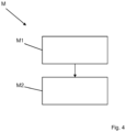
- Fig. 4 shows a schematic flow diagram of a method M for determining the number of passengers in an aircraft according to an embodiment of the present invention.
- a first method step M1 data concerning a cabin of the aircraft is collected by a plurality of sensors.
- the data collected by the plurality of sensors is evaluated by a computation unit in order to determine the number of passengers within the aircraft.
- the plurality of sensors collecting the data in method step M1 comprises at least one mm-wave-radar-sensor.
- Each of the plurality of sensors provides its own set of data concerning the cabin of the aircraft which the computation unit can evaluate, on its own or in combination to determine the number of passengers in the aircraft. Additionally, the computation unit can also evaluate the data provided by the plurality of sensors to determine the positions of passengers within the aircraft.
- the data of the respective sensor can be used to individually identify passengers and additionally their respective positions. In particular, this is possible with the data provided by the at least one mm-wave-sensor.
- Other sensor types which can provide data concerning individual passengers include visual cameras and infrared sensors.
- results of evaluating one set of data can be used to refine the results obtained by evaluating another set of data. For example, if evaluating the data provided by a mm-wave-radar-sensor is inconclusive as to whether one or two passengers are located at a certain position, data provided by for example a visual camera can be used to resolve this uncertainty.
- a light-barrier-sensor indicates that a passenger has passed through a door in a cabin wall
- all sensors can be treated equivalently, with all sensor data being initially processed separately and the final determination of the number and positions of passengers in the aircraft taking all sensors into account with equal weight.
- the indications of passengers provided by a mm-wave-radar-sensor can be given priority over conflicting indications provided by a camera if obscuring features, for example smoke, are present within the cabin which inhibit the function of the camera but not of the mm-wave-radar-sensor.
- the mm-wave-radar sensors 111 can be grouped together, as they are monitoring the same space within the cabin, albeit from different perspectives. In this case, every passenger within the field of view of one mm-wave-radar-sensor 111 should also be in the field of view of the other mm-wave-radar-sensor.
- the data provided by both mm-wave-radar-sensors 111 combined therefore provides more robust information with which to determine the number and positions of passengers within the space monitored by the mm-wave-radar-sensors 111.
- the mm-wave-radar-sensors 111 could be grouped together with the infrared sensors 113 and/or the light-barrier-sensors 114 associated with their respective door 12. As every passenger identified as passing through the door 12 by the mm-wave-radar-sensor 111 should be identified immediately before or after by the respective infrared sensor 113 of light-barrier-sensor 114, the combination of these data sets provides more robust information with which to determine whether a passenger has passed through the door 12.
- Such sub-groups can be exclusive, meaning every sensor is associated with only one sub-group. However, it is also possible that any given sensor is associated with more than one sub-group. It is not necessary that every sensor be associated with such a sub-group. For example, the camera 112 shown in Figure 3 can be associated with no sub-group.
- the simultaneous and synchronized acquisition of data by the various types of sensors provides especially robust results when determining the number of passengers in the aircraft.
- some sensors like mm-wave-radar-sensors, provide data that makes it difficult to differentiate pieces of luggage and passengers in a low position, like crawling on the floor.
- Other sensors like infrared-sensors, provide data in which this differentiation is particularly easy. Combining these types of sensor in a synchronized manner, greatly enhances the overall results when determining the number of passengers in the aircraft.
Landscapes
- Engineering & Computer Science (AREA)
- Radar, Positioning & Navigation (AREA)
- Remote Sensing (AREA)
- Physics & Mathematics (AREA)
- General Physics & Mathematics (AREA)
- Multimedia (AREA)
- Theoretical Computer Science (AREA)
- Computer Networks & Wireless Communication (AREA)
- Electromagnetism (AREA)
- Aviation & Aerospace Engineering (AREA)
- Human Computer Interaction (AREA)
- Radar Systems Or Details Thereof (AREA)
Abstract
Description
- The present invention is directed to a system for determining the number of passengers in a vehicle, a vehicle, and a method for determining the number of passengers in a vehicle.
- The present invention will be discussed mainly in the context of commercial flight and associated aircrafts. The present invention can however be applied to all fields in which multiple persons are transported with a singular vehicle, be it an aircraft, a train, a boat, or other.
- In the context of commercial travel, there are numerous situations in which it is necessary to know the number of passengers present within the transportation vehicle. Such situations include, but are not limited to, routine boarding and deboarding procedures as well as evacuations in case of emergency.
- The number of passengers in for example an aircraft is monitored by the cabin crew, for example by counting the number of passengers entering or exiting through doors in the cabin wall. The cabin crew is well trained and able to perform this task. However, in order to assist the cabin crew, automatic systems to determine the number of passengers in the aircraft would be advantageous.
- Such automatic systems would use various sensors to provide data which would then be evaluated in order to determine the number of passengers within the aircraft. Various types of sensors, including but not limited to visual cameras, infrared sensors, and light-barrier-sensors, are already employed in aircraft and other transportation vehicles. However, each of these sensors comes with distinct characteristics which can hinder their performance in various circumstances. For example, visual cameras and infrared sensors can be obscured, for example by smoke. Light-barrier-sensors can provide erroneous data if multiple passengers pass through the light barrier in close proximity, for example if one passenger is carried by one or more other passengers.
- In view of the above, it is an objective of the present invention to provide improved automated systems and method for determining the number of passengers in a vehicle.
- According to the present invention, this problem is solved by a system with the features of patent claim 1, a vehicle with the features of
patent claim 11, and a method with the features ofindependent claim 12. - To that effect, a first aspect of the invention provides a system for determining the number of passengers in a vehicle. The system comprises a plurality of sensors arranged to collect data concerning a cabin of the vehicle, wherein the plurality of sensors comprises at least one mm-wave-radar-sensor, and a computation unit, wherein the computation unit is connected to the plurality of sensors and configured to evaluate the data collected by the plurality of sensors in order to determine the number of passengers within the vehicle.
- A further aspect of the invention provides a vehicle, in particular an aircraft, comprising a system according to the present invention.
- A further aspect of the invention provides a method for determining the number of passengers in an vehicle. Data concerning a cabin of the vehicle is collected by a plurality of sensors, wherein the plurality of sensors comprises at least one mm-wave-radar sensor, and the data collected by the plurality of sensors is evaluated by a computation unit in order to determine the number of passengers within the vehicle.
- The applicant performed research in using mm-wave-radar-sensors in the context of monitoring passengers within a cabin of an aircraft. Mm-wave-radar-sensors emit electromagnetic signals with a wavelength in the mm range and use received reflections of said signals to identify objects, their location and movement. Generally speaking, the only objects moving within an aircraft cabin are the cabin crew, passengers, and other objects closely associated with either, for example luggage. Data provided by mm-wave-radar-sensors can therefore be used to identify passengers within an aircraft, in particular in situations where passengers are in motion, for example when entering or exiting the aircraft. Mm-wave-radar-sensors provide the advantage that obstruction obscuring the function of other sensors like visual cameras and infrared sensors, for example smoke, are transparent to mm-wave-radar-sensors which can therefore function unimpeded under such circumstances. The research performed by the applicant has also shown that singular mm-wave-radar-sensors still face some challenges at the moment as with the computing power presently available, the data generated by a singular mm-wave-radar-sensor cannot always provide an accurate reflection of the real situation under all circumstances.
- One idea of the present invention lies therefore in combining the data generated by multiple sensors, one of which is a mm-wave-radar-sensor, to improve the evaluation process used to determine the number of passengers in a vehicle from the data generated by each sensor individually. Through correct positioning of sensors and/or combining different types of sensors, the flaws of one singular sensor can be compensated by the other sensors leading to an overall improved performance of the automatic determination of the number of passengers within the vehicle.
- Advantageous embodiments and further developments are apparent from the further dependent claims and from the description with reference to the figures.
- According to an embodiment of the system least one of the plurality of sensors, in particular of the at least one mm-wave-radar-sensors, is arranged on a ceiling of the cabin. This position can provide an advantageously complete view of large portions of the cabin at once.
- According to a further embodiment of the system according at least one of the plurality of sensors, in particular of the at least one mm-wave-radar sensors, is arranged on a wall of the cabin. This positioning can provide an advantageously direct view of selected parts of the cabin and, depending on the type of sensor, can reduce the impact of reflection artifacts within the data generated.
- According to a further embodiment of the system at least one of the plurality of sensors, in particular of the at least one mm-wave-radar-sensors, is arranged in proximity to a door in the cabin wall, in particular above the door. As the number of passengers in the vehicle can only change through passengers passing through a door in the cabin wall, monitoring the space in the vicinity of such a door provides advantageously robust data for determining the number of passengers in the vehicle.
- According to an advantageous embodiment the at least one of the plurality of sensors is arranged to collect data concerning at least one of the interior side or the exterior side of the door. Passengers passing through a door have to pass through the space directly inside and outside the door, meaning that monitoring these spaces provides particularly robust results when determining the number of passengers in the vehicle.
- According to a further embodiment of the system plurality of sensors are arranged in sub-groups of at least two sensors, wherein the sensors of each sub-groups are arranged to collect data concerning a shared portion of the cabin. Such sub-groups can provide a particularly advantageous method of evaluating the data provided by the sensors in these sub-groups.
- According to an advantageous embodiment each sub-group comprises two sensors arranged opposite to each other on opposite walls of the cabin. In this case, the sensors monitor the same space within the cabin and their data can be evaluated in a particularly advantageous combination.
- According to a further embodiment the plurality of sensors comprises at least one of a camera, an infrared sensor, a light-barrier-sensor, or a weight sensor. Depending on circumstances, each of these sensor types can provide advantageously suited data for determining the number of passengers in the vehicle.
- According to a further embodiment of the system the computation unit is further configured to evaluate the data generated by the plurality of sensors in order to determine positions of passengers within the vehicle. Determining the positions of passengers provides further information which can be advantageously used when determining the number of passengers in the vehicle.
- According to a further embodiment the system further comprises at least one display unit connected to the computation unit and configured to display the results of the data evaluation performed by the computation unit. This advantageously allows to display the results of the data evaluation to personnel which needs to know the number of passengers in the vehicle to perform their duties, in particular to the cabin crew.
- According to a further embodiment of the method according the evaluating of data collected by the plurality of sensors comprises an identifying and synchronizing of passengers within the data collected by at least one of the plurality of sensors. Using multiple sensors in conjunction to identify individual passengers allows for a particularly robust evaluation of the data to determine the number of passengers in the vehicle.
- According to a further embodiment of the method the evaluating of data collected by at least one of the plurality of sensors takes into account the data collected by different one of the plurality of sensors. Depending on the situation, some sensors might provide more robust data than others. Prioritizing these sensors can improve the results of the data evaluation to determine the number of passengers in the vehicle.
- The above embodiments and further developments can be combined with each other as desired, if useful. Further possible embodiments, further developments and implementations of the invention also comprise combinations of features of the invention described above or below with respect to the embodiments which are not explicitly mentioned. In particular, the person skilled in the art will also add individual aspects as improvements or additions to the respective basic form of the present invention.
- The present invention is explained in more detail below with reference to the embodiments shown in the schematic figures.
- Fig. 1
- shows a schematic illustration of an aircraft according to an embodiment of the present invention;
- Fig. 2
- shows a schematic illustration of a system for determining the number of passengers in an aircraft according to an embodiment of the present invention;
- Fig. 3
- shows a schematic illustration of a cabin of an aircraft according to an embodiment of the present invention; and
- Fig. 4
- shows a schematic flow diagram of a method for determining the number of passengers in an aircraft according to an embodiment of the present invention.
- The accompanying figures are intended to provide a further understanding of embodiments of the invention. They illustrate embodiments and, in connection with the description, serve to explain principles and concepts of the invention. Other embodiments and many of the advantages mentioned will be apparent with reference to the drawings. The elements of the drawings are not necessarily shown to scale with respect to each other.
- In the figures of the drawings, identical elements, features and components that have the same function and the same effect are each given the same reference signs, unless otherwise specified.
-
Fig. 1 shows a schematic illustration of anaircraft 10 according to an embodiment of the present invention. In place of theaircraft 10 shown, any other mass transportation vehicle falls under the scope of the present invention. - The
aircraft 10 comprises asystem 100 for determining the number of passengers in theaircraft 10. The features and functions of thesystem 100 will be explained in further detail in the context ofFigures 2 to 4 . -
Fig. 2 shows a schematic illustration of asystem 100 for determining the number of passengers in an aircraft according to an embodiment of the present invention. - The
system 100 comprises a plurality ofsensors 110 and acomputation unit 120. The plurality ofsensors 110 comprises two sensors, one of which is a mm-wave-radar-sensor 111. The plurality ofsensors 110 are connected to thecomputation unit 120. Anoptional display unit 130 and its connection to thecomputation unit 120 are shown with dashed lines. - The plurality of
sensors 110 are configured to collect data concerning a cabin of an aircraft. Through the connection between the plurality ofsensors 110 and thecomputation unit 120, the collected data can be transferred to thecomputation unit 120, which is configured to evaluate the collected data in order to determine the number of passengers in the aircraft. This process will later be explained in more detail in the context ofFigure 4 . - The
optional display unit 130 preferably comprises a visual display for displaying the results of the evaluation performed by thecomputation unit 120. Additionally or alternatively, thedisplay unit 130 can be configured to provide audio cues concerning the results of the data evaluation, for example thedisplay unit 130 can provide an audio signal if the data evaluation determines that no passengers remain in the aircraft. Thesystem 100 can comprise more than onedisplay unit 130. Thedisplay unit 130 can be installed at a fixed location within the aircraft. Additionally or alternatively, thedisplay unit 130 can comprise a mobile device, in particular it can comprise a mobile device associated and in the possession of a member of the cabin crew. If more than onedisplay unit 130 is provided, each member of the cabin crew can be in possession of such a mobile device. - In
Figure 2 , the plurality ofsensors 110 comprises two sensors, one of which is explicitly a mm-wave-radar sensor 111. The other sensor can also be a mm-wave-radar sensor or can be a different type of sensor, in particular a camera, an infrared sensor, or a light-barrier-sensor. Other numbers and combinations of sensors fall under the scope of the present invention, in particular, all sensors of the plurality ofsensors 110 can be mm-wave-radar-sensors, independent of the number of sensors constituting the plurality of sensors. One exemplary embodiment of such a plurality of sensors will be explained in further detail in the context ofFigure 3 . -
Fig. 3 shows a schematic illustration of acabin 11 of an aircraft according to an embodiment of the present invention. - The
cabin 11 is shown in profile. The aircraft comprises twodoors 12, integrated into opposite walls of thecabin 11. Two mm-wave-radar-sensors 111 are arranged on interior sides of opposite walls of thecabin 11, above therespective doors 12. Acamera 112 is arranged on a ceiling of the cabin. Twoinfrared sensors 113 are arranged on exterior sides of opposite walls of thecabin 11, above therespective doors 12. Two light-barrier-sensors 114 are arranged in the frames of therespective doors 12. - The mm-wave-radar-
sensors 111, theinfrared sensors 113, and the light-barrier-sensors 114, are all located in proximity to thedoors 12. As the number of passengers in the aircraft can only change by passengers entering or exiting through one of thedoors 12, collecting data concerning the vicinity of thedoors 12 can provide the most reliable information in order to determine the number of passengers in the aircraft. - The mm-wave-radar-
sensors 111 are located above thedoors 12 and monitor the interior of thecabin 11. Passengers entering or exiting the aircraft will generally move away or towards thedoors 12 respectively with only a minimum amount of lateral movement regarding thedoors 12. Under these circumstances, the mm-wave-radar-sensors 111 can be particularly well suited to identify passengers within the aircraft. - The
camera 112 is arranged on a ceiling of thecabin 11. Although the profile perspective ofFigure 3 shows the camera in the same plane as thedoors 12, thecamera 113 can be located at any point within thecabin 11. The location at the ceiling of thecabin 11 gives the camera 112 a particularly good vantage point, as there should only be minimal obstruction between thecamera 112 and the parts of thecabin 11 where passengers can be located. Thecamera 112 can in particular comprise a fisheye lens, giving a camera an advantageously wide field of view. Additionally or alternatively, a mm-wave-radar-sensor can be provided at the location of thecamera 112. -
Infrared sensors 113 are arranged above thedoors 12 monitoring the exterior of the aircraft in close proximity to thedoors 12. As humans generally have a higher body temperature than the ambient environment, theinfrared sensors 113 can be particularly well suited to identifying passengers outside the aircraft, even when visual obstructions, for example vegetation or rocks, are present in the vicinity of the aircraft. Additionally or alternatively, further mm-wave-radar-sensors can be located at the positions of theinfrared sensors 113. As passengers generally exit thedoors 12 and subsequently move away from the aircraft in essentially a straight line, mm-wave-radar-sensors can be particularly well suited of identifying passengers under these circumstances. - Light-barrier-
sensors 114 are arranged in the frames of thedoors 12. Passengers crossing through the door, either entering or exiting, momentarily interrupt the light barrier, which can therefore determine when at least one passenger has entered or exited the aircraft. This information is particularly well suited to allow a computation unit to correctly evaluate the data provided by the other sensors. Additionally or alternatively, a weight sensor can be provided at the location of the light-barrier-sensors 114 to detect passengers passing through the door. -
Fig. 4 shows a schematic flow diagram of a method M for determining the number of passengers in an aircraft according to an embodiment of the present invention. - In a first method step M1, data concerning a cabin of the aircraft is collected by a plurality of sensors. In a second method step M2, the data collected by the plurality of sensors is evaluated by a computation unit in order to determine the number of passengers within the aircraft. According to the present invention, the plurality of sensors collecting the data in method step M1 comprises at least one mm-wave-radar-sensor.
- Each of the plurality of sensors provides its own set of data concerning the cabin of the aircraft which the computation unit can evaluate, on its own or in combination to determine the number of passengers in the aircraft. Additionally, the computation unit can also evaluate the data provided by the plurality of sensors to determine the positions of passengers within the aircraft.
- Depending on the type of sensor, the data of the respective sensor can be used to individually identify passengers and additionally their respective positions. In particular, this is possible with the data provided by the at least one mm-wave-sensor. Other sensor types which can provide data concerning individual passengers include visual cameras and infrared sensors. As multiple sets of data are available, results of evaluating one set of data can be used to refine the results obtained by evaluating another set of data. For example, if evaluating the data provided by a mm-wave-radar-sensor is inconclusive as to whether one or two passengers are located at a certain position, data provided by for example a visual camera can be used to resolve this uncertainty. In another example, if a light-barrier-sensor indicates that a passenger has passed through a door in a cabin wall, it can be determined whether a set of data points provided by a mm-wave-radar-sensor associated with said door indicates the presence of a passenger or of a different obstruction.
- For this evaluation, all sensors can be treated equivalently, with all sensor data being initially processed separately and the final determination of the number and positions of passengers in the aircraft taking all sensors into account with equal weight. Depending on the situation, it can be advantageous to prioritize the data provided by some sensors over others when the initial data processing produces conflicting results. For example, the indication that a passenger has passed through a door provided by light-barrier sensor can be given priority over an indication that said passenger is still within the field of view of a corresponding mm-wave-radar-sensor. In another example, the indications of passengers provided by a mm-wave-radar-sensor can be given priority over conflicting indications provided by a camera if obscuring features, for example smoke, are present within the cabin which inhibit the function of the camera but not of the mm-wave-radar-sensor.
- It can also be advantageous to group the sensors into sub-groups and evaluate the data provided by the sensors in such a sub-group in conjunction. Referring to
Figure 3 , the mm-wave-radar sensors 111 can be grouped together, as they are monitoring the same space within the cabin, albeit from different perspectives. In this case, every passenger within the field of view of one mm-wave-radar-sensor 111 should also be in the field of view of the other mm-wave-radar-sensor. The data provided by both mm-wave-radar-sensors 111 combined therefore provides more robust information with which to determine the number and positions of passengers within the space monitored by the mm-wave-radar-sensors 111. Additionally or alternatively, the mm-wave-radar-sensors 111 could be grouped together with theinfrared sensors 113 and/or the light-barrier-sensors 114 associated with theirrespective door 12. As every passenger identified as passing through thedoor 12 by the mm-wave-radar-sensor 111 should be identified immediately before or after by the respectiveinfrared sensor 113 of light-barrier-sensor 114, the combination of these data sets provides more robust information with which to determine whether a passenger has passed through thedoor 12. Such sub-groups can be exclusive, meaning every sensor is associated with only one sub-group. However, it is also possible that any given sensor is associated with more than one sub-group. It is not necessary that every sensor be associated with such a sub-group. For example, thecamera 112 shown inFigure 3 can be associated with no sub-group. - The simultaneous and synchronized acquisition of data by the various types of sensors, as shown in the exemplary embodiments of the drawings, provides especially robust results when determining the number of passengers in the aircraft. For example, some sensors, like mm-wave-radar-sensors, provide data that makes it difficult to differentiate pieces of luggage and passengers in a low position, like crawling on the floor. Other sensors, like infrared-sensors, provide data in which this differentiation is particularly easy. Combining these types of sensor in a synchronized manner, greatly enhances the overall results when determining the number of passengers in the aircraft.
-
- 10
- aircraft
- 11
- cabin
- 12
- door
- 100
- system
- 110
- plurality of sensors
- 111
- mm-wave-radar-sensor
- 112
- camera
- 113
- infrared sensor
- 114
- light-barrier sensor
- 120
- computation unit
- 130
- display unit
- M
- method
- M1
- method step of collecting data
- M2
- method step of evaluating data
Claims (14)
- System (100) for determining the number of passengers in a vehicle, comprising:a plurality of sensors (110) arranged to collect data concerning a cabin (11) of the vehicle, wherein the plurality of sensors (110) comprises at least one mm-wave-radar-sensor (111); anda computation unit (120), wherein the computation unit (120) is connected to the plurality of sensors (110) and configured to evaluate the data collected by the plurality of sensors (110) in order to determine the number of passengers within the vehicle.
- System (100) according to claim 1, wherein at least one of the plurality of sensors (110), in particular of the at least one mm-wave-radar-sensors (111), is arranged on a ceiling of the cabin (11).
- System (100) according to claim 1 or 2, wherein at least one of the plurality of sensors (110), in particular of the at least one mm-wave-radar sensors (111), is arranged on a wall of the cabin (11).
- System (100) according to any one of the preceding claims, wherein at least one of the plurality of sensors (110), in particular of the at least one mm-wave-radar-sensors (111), is arranged in proximity to a door (12) in the cabin wall, in particular above the door (12).
- System (100) according to claim 4, wherein the at least one of the plurality of sensors (110) is arranged to collect data concerning at least one of the interior side or the exterior side of the door.
- System (100) according to any one of the preceding claims, wherein the plurality of sensors (110) are arranged in sub-groups of at least two sensors, wherein the sensors of each sub-group are arranged to collect data concerning a shared portion of the cabin (11).
- System (100) according to claim 6, wherein each sub-group comprises two sensors arranged opposite to each other on opposite walls of the cabin (11).
- System (100) according to any one of the preceding claims, wherein the plurality of sensors (110) comprises at least one of a camera (112), an infrared sensor (113), a light-barrier-sensor (114), or a weight sensor.
- System (100) according to any one of the preceding claims, wherein the computation unit (120) is further configured to evaluate the data generated by the plurality of sensors (110) in order to determine positions of passengers within the vehicle.
- System (100) according to any one of the preceding claims, further comprising at least one display unit (130) connected to the computation unit (120) and configured to display the results of the data evaluation performed by the computation unit (120).
- Vehicle, in particular an aircraft (10), comprising a system (100) according to any one of the preceding claims.
- Method (M) for determining the number of passengers in a vehicle, wherein the method (M) comprises:collecting data (M1) concerning a cabin (11) of the vehicle by a plurality of sensors (110), wherein the plurality of sensors (110) comprises at least one mm-wave-radar sensor (111); andevaluating (M2) the data collected by the plurality of sensors (110) by a computation unit (120) in order to determine the number of passengers within the vehicle.
- Method (M) according to claim 12, wherein the evaluating (M2) of data collected by the plurality of sensors (110) comprises an identifying and synchronizing of passengers within the data collected by at least one of the plurality of sensors (110).
- Method (M) according to claim 12 or 13, wherein the evaluating (M2) of data collected by at least one of the plurality of sensors (110) takes into account the data collected by different one of the plurality of sensors (110).
Priority Applications (2)
| Application Number | Priority Date | Filing Date | Title |
|---|---|---|---|
| EP22193569.5A EP4332626B1 (en) | 2022-09-01 | 2022-09-01 | System for determining the number of passengers in a vehicle, vehicle, and method for determining the number of passengers in a vehicle |
| US18/458,336 US20240076058A1 (en) | 2022-09-01 | 2023-08-30 | System for determining the number of passengers in a vehicle, vehicle, and method for determining the number of passengers in a vehicle |
Applications Claiming Priority (1)
| Application Number | Priority Date | Filing Date | Title |
|---|---|---|---|
| EP22193569.5A EP4332626B1 (en) | 2022-09-01 | 2022-09-01 | System for determining the number of passengers in a vehicle, vehicle, and method for determining the number of passengers in a vehicle |
Publications (2)
| Publication Number | Publication Date |
|---|---|
| EP4332626A1 true EP4332626A1 (en) | 2024-03-06 |
| EP4332626B1 EP4332626B1 (en) | 2025-12-24 |
Family
ID=83447971
Family Applications (1)
| Application Number | Title | Priority Date | Filing Date |
|---|---|---|---|
| EP22193569.5A Active EP4332626B1 (en) | 2022-09-01 | 2022-09-01 | System for determining the number of passengers in a vehicle, vehicle, and method for determining the number of passengers in a vehicle |
Country Status (2)
| Country | Link |
|---|---|
| US (1) | US20240076058A1 (en) |
| EP (1) | EP4332626B1 (en) |
Cited By (1)
| Publication number | Priority date | Publication date | Assignee | Title |
|---|---|---|---|---|
| US20240177502A1 (en) * | 2022-11-30 | 2024-05-30 | Hon Hai Precision Industry Co., Ltd. | Method of determining degree of congestion of compartment, electronic device and storage medium |
Families Citing this family (1)
| Publication number | Priority date | Publication date | Assignee | Title |
|---|---|---|---|---|
| US20260061967A1 (en) * | 2024-09-04 | 2026-03-05 | Textron Inc. | User profiles for consumers |
Citations (4)
| Publication number | Priority date | Publication date | Assignee | Title |
|---|---|---|---|---|
| US20010029416A1 (en) * | 1992-05-05 | 2001-10-11 | Breed David S. | Vehicular component control systems and methods |
| US20080236275A1 (en) * | 2002-06-11 | 2008-10-02 | Intelligent Technologies International, Inc. | Remote Monitoring of Fluid Storage Tanks |
| US20200290567A1 (en) * | 2019-03-14 | 2020-09-17 | Iee International Electronics & Engineering S.A. | Vehicle occupant detection |
| EP4001958A1 (en) * | 2020-11-12 | 2022-05-25 | Continental Automotive GmbH | Passenger counting device and public transport vehicle |
Family Cites Families (6)
| Publication number | Priority date | Publication date | Assignee | Title |
|---|---|---|---|---|
| JPWO2013183653A1 (en) * | 2012-06-04 | 2016-02-01 | 株式会社フジクラ | Occupant position detection device and airbag deployment control system |
| US20140327752A1 (en) * | 2013-05-01 | 2014-11-06 | Nissan North America, Inc. | Vehicle occupancy detection system |
| US11036226B2 (en) * | 2019-01-24 | 2021-06-15 | Ford Global Technologies, Llc | System and method for preventing unwanted dismissal of autonomous vehicle |
| US11951875B2 (en) * | 2020-10-14 | 2024-04-09 | International Business Machines Corporation | Multi-sensor life detection within vehicles |
| US11807258B2 (en) * | 2021-06-08 | 2023-11-07 | Toyota Connected North America, Inc. | Radar detection of unsafe seating conditions in a vehicle |
| US12594974B2 (en) * | 2023-12-27 | 2026-04-07 | Dish Network Technologies India Private Limited | Multi-carriage vehicle boarding recommendations |
-
2022
- 2022-09-01 EP EP22193569.5A patent/EP4332626B1/en active Active
-
2023
- 2023-08-30 US US18/458,336 patent/US20240076058A1/en active Pending
Patent Citations (4)
| Publication number | Priority date | Publication date | Assignee | Title |
|---|---|---|---|---|
| US20010029416A1 (en) * | 1992-05-05 | 2001-10-11 | Breed David S. | Vehicular component control systems and methods |
| US20080236275A1 (en) * | 2002-06-11 | 2008-10-02 | Intelligent Technologies International, Inc. | Remote Monitoring of Fluid Storage Tanks |
| US20200290567A1 (en) * | 2019-03-14 | 2020-09-17 | Iee International Electronics & Engineering S.A. | Vehicle occupant detection |
| EP4001958A1 (en) * | 2020-11-12 | 2022-05-25 | Continental Automotive GmbH | Passenger counting device and public transport vehicle |
Cited By (2)
| Publication number | Priority date | Publication date | Assignee | Title |
|---|---|---|---|---|
| US20240177502A1 (en) * | 2022-11-30 | 2024-05-30 | Hon Hai Precision Industry Co., Ltd. | Method of determining degree of congestion of compartment, electronic device and storage medium |
| US12488600B2 (en) * | 2022-11-30 | 2025-12-02 | Hon Hai Precision Industry Co., Ltd. | Method of determining degree of congestion of compartment, electronic device and storage medium |
Also Published As
| Publication number | Publication date |
|---|---|
| EP4332626B1 (en) | 2025-12-24 |
| US20240076058A1 (en) | 2024-03-07 |
Similar Documents
| Publication | Publication Date | Title |
|---|---|---|
| EP2801956B1 (en) | Passenger counter | |
| EP4332626B1 (en) | System for determining the number of passengers in a vehicle, vehicle, and method for determining the number of passengers in a vehicle | |
| CN111694065B (en) | Mobile | |
| CN106463059B (en) | Obstacle Information Management Device | |
| EP2883209B1 (en) | Strike detection using video images | |
| EP1074958B1 (en) | Traffic congestion measuring method and device and applications thereof | |
| EP3098190A1 (en) | Flexible destination dispatch passenger support system | |
| JP2014028667A (en) | Escalator monitoring system | |
| US6712269B1 (en) | Counting apparatus | |
| KR20220055167A (en) | Autonomous robot, world map management server of autonomous robot and collision avoidance method using the same | |
| CN101385059A (en) | Aircraft collision sense and avoidance system and method | |
| EP3276572A1 (en) | Evacuation guiding system and method for ship | |
| JP2022008167A (en) | Object monitoring system for aircraft | |
| KR102226183B1 (en) | Monitoring system for building occupant density using cctv, and method for the same | |
| CN113993763A (en) | Monitoring system for infrastructure and/or vehicle with event detection | |
| JP2022138598A (en) | Traveling support control device, traveling support control method, and traveling support control program | |
| CN109919066A (en) | The method and apparatus of passenger's density anomaly in a kind of detection rail transit cars | |
| US6600509B1 (en) | Detection system | |
| KR20230150020A (en) | Real-time parking lot informatioin smart guiding sysmem | |
| JP2009199109A (en) | New transportation system and its passenger management method | |
| US11525937B2 (en) | Registration system | |
| BG113786A (en) | RAILWAY TRAIN EQUIPMENT FOR DETECTION OF OBJECTS AND THEIR SUBSEQUENT CLASSIFICATION | |
| JP2011230750A (en) | Monitoring system | |
| JP7491204B2 (en) | Monitoring system, monitoring method, monitoring device, and monitoring program | |
| JP7031817B2 (en) | Surveillance systems, surveillance programs, and storage media |
Legal Events
| Date | Code | Title | Description |
|---|---|---|---|
| PUAI | Public reference made under article 153(3) epc to a published international application that has entered the european phase |
Free format text: ORIGINAL CODE: 0009012 |
|
| STAA | Information on the status of an ep patent application or granted ep patent |
Free format text: STATUS: THE APPLICATION HAS BEEN PUBLISHED |
|
| AK | Designated contracting states |
Kind code of ref document: A1 Designated state(s): AL AT BE BG CH CY CZ DE DK EE ES FI FR GB GR HR HU IE IS IT LI LT LU LV MC MK MT NL NO PL PT RO RS SE SI SK SM TR |
|
| STAA | Information on the status of an ep patent application or granted ep patent |
Free format text: STATUS: REQUEST FOR EXAMINATION WAS MADE |
|
| 17P | Request for examination filed |
Effective date: 20240906 |
|
| RBV | Designated contracting states (corrected) |
Designated state(s): AL AT BE BG CH CY CZ DE DK EE ES FI FR GB GR HR HU IE IS IT LI LT LU LV MC MK MT NL NO PL PT RO RS SE SI SK SM TR |
|
| GRAP | Despatch of communication of intention to grant a patent |
Free format text: ORIGINAL CODE: EPIDOSNIGR1 |
|
| STAA | Information on the status of an ep patent application or granted ep patent |
Free format text: STATUS: GRANT OF PATENT IS INTENDED |
|
| INTG | Intention to grant announced |
Effective date: 20250917 |
|
| GRAS | Grant fee paid |
Free format text: ORIGINAL CODE: EPIDOSNIGR3 |
|
| GRAA | (expected) grant |
Free format text: ORIGINAL CODE: 0009210 |
|
| STAA | Information on the status of an ep patent application or granted ep patent |
Free format text: STATUS: THE PATENT HAS BEEN GRANTED |
|
| AK | Designated contracting states |
Kind code of ref document: B1 Designated state(s): AL AT BE BG CH CY CZ DE DK EE ES FI FR GB GR HR HU IE IS IT LI LT LU LV MC MK MT NL NO PL PT RO RS SE SI SK SM TR |
|
| REG | Reference to a national code |
Ref country code: CH Ref legal event code: F10 Free format text: ST27 STATUS EVENT CODE: U-0-0-F10-F00 (AS PROVIDED BY THE NATIONAL OFFICE) Effective date: 20251224 Ref country code: GB Ref legal event code: FG4D |
|
| REG | Reference to a national code |
Ref country code: DE Ref legal event code: R096 Ref document number: 602022027316 Country of ref document: DE |
|
| REG | Reference to a national code |
Ref country code: LT Ref legal event code: MG9D |
|
| PG25 | Lapsed in a contracting state [announced via postgrant information from national office to epo] |
Ref country code: NO Free format text: LAPSE BECAUSE OF FAILURE TO SUBMIT A TRANSLATION OF THE DESCRIPTION OR TO PAY THE FEE WITHIN THE PRESCRIBED TIME-LIMIT Effective date: 20260324 |
|
| PG25 | Lapsed in a contracting state [announced via postgrant information from national office to epo] |
Ref country code: FI Free format text: LAPSE BECAUSE OF FAILURE TO SUBMIT A TRANSLATION OF THE DESCRIPTION OR TO PAY THE FEE WITHIN THE PRESCRIBED TIME-LIMIT Effective date: 20251224 Ref country code: HR Free format text: LAPSE BECAUSE OF FAILURE TO SUBMIT A TRANSLATION OF THE DESCRIPTION OR TO PAY THE FEE WITHIN THE PRESCRIBED TIME-LIMIT Effective date: 20251224 |
|
| PG25 | Lapsed in a contracting state [announced via postgrant information from national office to epo] |
Ref country code: RS Free format text: LAPSE BECAUSE OF FAILURE TO SUBMIT A TRANSLATION OF THE DESCRIPTION OR TO PAY THE FEE WITHIN THE PRESCRIBED TIME-LIMIT Effective date: 20260324 |
|
| PG25 | Lapsed in a contracting state [announced via postgrant information from national office to epo] |
Ref country code: LV Free format text: LAPSE BECAUSE OF FAILURE TO SUBMIT A TRANSLATION OF THE DESCRIPTION OR TO PAY THE FEE WITHIN THE PRESCRIBED TIME-LIMIT Effective date: 20251224 |
|
| REG | Reference to a national code |
Ref country code: NL Ref legal event code: MP Effective date: 20251224 |
|
| PG25 | Lapsed in a contracting state [announced via postgrant information from national office to epo] |
Ref country code: BG Free format text: LAPSE BECAUSE OF FAILURE TO SUBMIT A TRANSLATION OF THE DESCRIPTION OR TO PAY THE FEE WITHIN THE PRESCRIBED TIME-LIMIT Effective date: 20251224 |