EP4332479A2 - Refrigerated storage structure - Google Patents
Refrigerated storage structure Download PDFInfo
- Publication number
- EP4332479A2 EP4332479A2 EP24153085.6A EP24153085A EP4332479A2 EP 4332479 A2 EP4332479 A2 EP 4332479A2 EP 24153085 A EP24153085 A EP 24153085A EP 4332479 A2 EP4332479 A2 EP 4332479A2
- Authority
- EP
- European Patent Office
- Prior art keywords
- sealing member
- insulated
- storage assembly
- drawer
- heat exchanger
- Prior art date
- Legal status (The legal status is an assumption and is not a legal conclusion. Google has not performed a legal analysis and makes no representation as to the accuracy of the status listed.)
- Withdrawn
Links
- 238000007789 sealing Methods 0.000 claims abstract description 34
- 238000005057 refrigeration Methods 0.000 claims abstract description 27
- 238000001816 cooling Methods 0.000 claims description 5
- 238000010438 heat treatment Methods 0.000 claims description 4
- 239000000853 adhesive Substances 0.000 claims description 3
- 230000001070 adhesive effect Effects 0.000 claims description 3
- 239000013536 elastomeric material Substances 0.000 claims description 2
- 239000003507 refrigerant Substances 0.000 description 12
- 239000000463 material Substances 0.000 description 7
- 239000012774 insulation material Substances 0.000 description 5
- 238000000034 method Methods 0.000 description 4
- 230000008569 process Effects 0.000 description 4
- 230000005494 condensation Effects 0.000 description 3
- 238000009833 condensation Methods 0.000 description 3
- 238000001704 evaporation Methods 0.000 description 3
- 229920002725 thermoplastic elastomer Polymers 0.000 description 3
- 229920002943 EPDM rubber Polymers 0.000 description 2
- VYPSYNLAJGMNEJ-UHFFFAOYSA-N Silicium dioxide Chemical compound O=[Si]=O VYPSYNLAJGMNEJ-UHFFFAOYSA-N 0.000 description 2
- 235000013361 beverage Nutrition 0.000 description 2
- 230000008020 evaporation Effects 0.000 description 2
- 238000009413 insulation Methods 0.000 description 2
- 239000007788 liquid Substances 0.000 description 2
- 230000037361 pathway Effects 0.000 description 2
- OKTJSMMVPCPJKN-UHFFFAOYSA-N Carbon Chemical compound [C] OKTJSMMVPCPJKN-UHFFFAOYSA-N 0.000 description 1
- 230000005679 Peltier effect Effects 0.000 description 1
- 230000004913 activation Effects 0.000 description 1
- 239000002390 adhesive tape Substances 0.000 description 1
- 239000000956 alloy Substances 0.000 description 1
- 229910045601 alloy Inorganic materials 0.000 description 1
- XAGFODPZIPBFFR-UHFFFAOYSA-N aluminium Chemical compound [Al] XAGFODPZIPBFFR-UHFFFAOYSA-N 0.000 description 1
- 229910052782 aluminium Inorganic materials 0.000 description 1
- 230000000712 assembly Effects 0.000 description 1
- 238000000429 assembly Methods 0.000 description 1
- 230000004888 barrier function Effects 0.000 description 1
- 229910052799 carbon Inorganic materials 0.000 description 1
- 230000008859 change Effects 0.000 description 1
- 230000007423 decrease Effects 0.000 description 1
- 239000013013 elastic material Substances 0.000 description 1
- 229920001971 elastomer Polymers 0.000 description 1
- 239000000806 elastomer Substances 0.000 description 1
- 239000012530 fluid Substances 0.000 description 1
- 229910021485 fumed silica Inorganic materials 0.000 description 1
- 239000011810 insulating material Substances 0.000 description 1
- 230000000149 penetrating effect Effects 0.000 description 1
- 239000004033 plastic Substances 0.000 description 1
- 229920003023 plastic Polymers 0.000 description 1
- 229920000642 polymer Polymers 0.000 description 1
- 239000004800 polyvinyl chloride Substances 0.000 description 1
- 239000000843 powder Substances 0.000 description 1
- 230000004044 response Effects 0.000 description 1
- 229920003031 santoprene Polymers 0.000 description 1
- 229910052814 silicon oxide Inorganic materials 0.000 description 1
- XLYOFNOQVPJJNP-UHFFFAOYSA-N water Substances O XLYOFNOQVPJJNP-UHFFFAOYSA-N 0.000 description 1
Images



Classifications
-
- F—MECHANICAL ENGINEERING; LIGHTING; HEATING; WEAPONS; BLASTING
- F25—REFRIGERATION OR COOLING; COMBINED HEATING AND REFRIGERATION SYSTEMS; HEAT PUMP SYSTEMS; MANUFACTURE OR STORAGE OF ICE; LIQUEFACTION SOLIDIFICATION OF GASES
- F25D—REFRIGERATORS; COLD ROOMS; ICE-BOXES; COOLING OR FREEZING APPARATUS NOT OTHERWISE PROVIDED FOR
- F25D23/00—General constructional features
- F25D23/06—Walls
- F25D23/062—Walls defining a cabinet
-
- F—MECHANICAL ENGINEERING; LIGHTING; HEATING; WEAPONS; BLASTING
- F25—REFRIGERATION OR COOLING; COMBINED HEATING AND REFRIGERATION SYSTEMS; HEAT PUMP SYSTEMS; MANUFACTURE OR STORAGE OF ICE; LIQUEFACTION SOLIDIFICATION OF GASES
- F25B—REFRIGERATION MACHINES, PLANTS OR SYSTEMS; COMBINED HEATING AND REFRIGERATION SYSTEMS; HEAT PUMP SYSTEMS
- F25B21/00—Machines, plants or systems, using electric or magnetic effects
- F25B21/02—Machines, plants or systems, using electric or magnetic effects using Peltier effect; using Nernst-Ettinghausen effect
-
- F—MECHANICAL ENGINEERING; LIGHTING; HEATING; WEAPONS; BLASTING
- F25—REFRIGERATION OR COOLING; COMBINED HEATING AND REFRIGERATION SYSTEMS; HEAT PUMP SYSTEMS; MANUFACTURE OR STORAGE OF ICE; LIQUEFACTION SOLIDIFICATION OF GASES
- F25B—REFRIGERATION MACHINES, PLANTS OR SYSTEMS; COMBINED HEATING AND REFRIGERATION SYSTEMS; HEAT PUMP SYSTEMS
- F25B25/00—Machines, plants or systems, using a combination of modes of operation covered by two or more of the groups F25B1/00 - F25B23/00
-
- F—MECHANICAL ENGINEERING; LIGHTING; HEATING; WEAPONS; BLASTING
- F25—REFRIGERATION OR COOLING; COMBINED HEATING AND REFRIGERATION SYSTEMS; HEAT PUMP SYSTEMS; MANUFACTURE OR STORAGE OF ICE; LIQUEFACTION SOLIDIFICATION OF GASES
- F25D—REFRIGERATORS; COLD ROOMS; ICE-BOXES; COOLING OR FREEZING APPARATUS NOT OTHERWISE PROVIDED FOR
- F25D23/00—General constructional features
- F25D23/006—General constructional features for mounting refrigerating machinery components
-
- F—MECHANICAL ENGINEERING; LIGHTING; HEATING; WEAPONS; BLASTING
- F25—REFRIGERATION OR COOLING; COMBINED HEATING AND REFRIGERATION SYSTEMS; HEAT PUMP SYSTEMS; MANUFACTURE OR STORAGE OF ICE; LIQUEFACTION SOLIDIFICATION OF GASES
- F25D—REFRIGERATORS; COLD ROOMS; ICE-BOXES; COOLING OR FREEZING APPARATUS NOT OTHERWISE PROVIDED FOR
- F25D25/00—Charging, supporting, and discharging the articles to be cooled
- F25D25/02—Charging, supporting, and discharging the articles to be cooled by shelves
- F25D25/024—Slidable shelves
- F25D25/025—Drawers
-
- F—MECHANICAL ENGINEERING; LIGHTING; HEATING; WEAPONS; BLASTING
- F25—REFRIGERATION OR COOLING; COMBINED HEATING AND REFRIGERATION SYSTEMS; HEAT PUMP SYSTEMS; MANUFACTURE OR STORAGE OF ICE; LIQUEFACTION SOLIDIFICATION OF GASES
- F25B—REFRIGERATION MACHINES, PLANTS OR SYSTEMS; COMBINED HEATING AND REFRIGERATION SYSTEMS; HEAT PUMP SYSTEMS
- F25B2321/00—Details of machines, plants or systems, using electric or magnetic effects
- F25B2321/02—Details of machines, plants or systems, using electric or magnetic effects using Peltier effects; using Nernst-Ettinghausen effects
- F25B2321/023—Mounting details thereof
-
- F—MECHANICAL ENGINEERING; LIGHTING; HEATING; WEAPONS; BLASTING
- F25—REFRIGERATION OR COOLING; COMBINED HEATING AND REFRIGERATION SYSTEMS; HEAT PUMP SYSTEMS; MANUFACTURE OR STORAGE OF ICE; LIQUEFACTION SOLIDIFICATION OF GASES
- F25D—REFRIGERATORS; COLD ROOMS; ICE-BOXES; COOLING OR FREEZING APPARATUS NOT OTHERWISE PROVIDED FOR
- F25D2201/00—Insulation
- F25D2201/10—Insulation with respect to heat
- F25D2201/14—Insulation with respect to heat using subatmospheric pressure
-
- F—MECHANICAL ENGINEERING; LIGHTING; HEATING; WEAPONS; BLASTING
- F25—REFRIGERATION OR COOLING; COMBINED HEATING AND REFRIGERATION SYSTEMS; HEAT PUMP SYSTEMS; MANUFACTURE OR STORAGE OF ICE; LIQUEFACTION SOLIDIFICATION OF GASES
- F25D—REFRIGERATORS; COLD ROOMS; ICE-BOXES; COOLING OR FREEZING APPARATUS NOT OTHERWISE PROVIDED FOR
- F25D23/00—General constructional features
- F25D23/08—Parts formed wholly or mainly of plastics materials
- F25D23/082—Strips
- F25D23/087—Sealing strips
Definitions
- the present disclosure relates to a household appliance such as a refrigerator or a refrigerated storage cabinet.
- Refrigerators must maintain a low temperature to prevent food and beverages from spoiling while being stored within a food storage space.
- the food storage space may be insulated to block or mitigate heat from outside air from penetrating the food storage space.
- the food storage space may be formed of an insulative structure and may include one or more heat exchangers that may absorb heat inside the food storage space or dissipate heat to an area external to the food storage area.
- a storage assembly includes a vacuum insulated cabinet, a refrigeration system, and a drawer.
- the vacuum insulated cabinet may be formed by a number of insulated panels.
- the vacuum insulated cabinet and the refrigeration system may collectively form a refrigerated compartment.
- the drawer may be configured to move between an open position, in which an interior portion of the drawer is accessible, and a closed position, in which the drawer is disposed in the refrigerated compartment and the interior portion of the drawer is inaccessible.
- the refrigeration system may include a first heat exchanger, that may be disposed between the drawer and a rear portion of the insulated cabinet, and a second heat exchanger that may be disposed in a machine compartment adjacent to the refrigerated compartment.
- a base is disposed beneath the vacuum insulated cabinet and partially defines the machine compartment.
- the first heat exchanger is a thermoelectric cooling plate configured to refrigerate the refrigerated compartment.
- a fan is fixed to the thermoelectric cooling plate and is configured to direct air towards the drawer.
- the second heat exchanger is a thermoelectric heating plate configured to dissipate heat away from the refrigerated compartment.
- a fan is fixed to the thermoelectric heating plate and is configured to direct air away from the insulated cabinet.
- the rear portion is formed by a rear insulated panel of the number of insulated panels.
- the rear insulated panel defines an aperture configured to receive at least one of the first heat exchanger or the second heat exchanger.
- the storage assembly further comprises a first sealing member lying along an outer periphery of the second heat exchanger.
- the storage assembly further comprises a second sealing member lying along the first sealing member.
- a first insulated panel of the number of insulated panels forces the second sealing member into contact with the first sealing member.
- the second sealing member includes a first vertical leg, a second vertical leg, and a horizontal leg extending therebetween.
- the first insulated panel includes a liner sheet fixed to the first leg of the sealing member.
- the first insulated panel includes a wrapper sheet and a portion of the wrapper sheet lies along the second leg.
- an adhesive is disposed between and fixes the liner sheet to the first leg of the sealing member.
- the first sealing member includes a lip disposed between the first heat exchanger and the first leg of the second sealing member.
- the lip is formed of an elastomeric material.
- the first leg of the second sealing member and the liner sheet are positioned to contact the lip such that the lip elastically deforms from a nominal position.
- a storage assembly includes a vacuum insulated cabinet, a base, a refrigeration system, and a drawer.
- the vacuum insulated cabinet may be formed by a number of insulated panels.
- the vacuum insulated cabinet and the refrigeration system may collectively form a refrigerated compartment.
- the base may be disposed beneath the vacuum insulated cabinet and may partially define a machine compartment.
- the refrigeration system may include an evaporator that may be disposed in the refrigerated compartment and a condenser that may be disposed between the base and the vacuum insulated cabinet.
- a compressor is disposed in the machine compartment.
- the number of insulated panels includes a rear insulated panel provided with a first side and a second side, where the first side is disposed closer to the drawer than the second side, and where a portion of the machine compartment is formed by the second side.
- the base includes a first portion and a second portion.
- the first portion carries the compressor and the second portion carries the condenser.
- a drain pan is disposed in the machine compartment and is carried by the second portion.
- a storage assembly includes a vacuum insulated cabinet, a refrigeration system, and a drawer.
- the vacuum insulated cabinet may be formed by a number of insulated panels.
- the vacuum insulated cabinet and the refrigeration system may collectively form a refrigerated compartment.
- the drawer may be configured to move between an open position, in which an interior portion of the drawer is accessible, and a closed position, in which the drawer is disposed in the refrigerated compartment and the interior portion of the drawer is inaccessible.
- the refrigeration system may include a first thermoelectric device, that may be disposed between the drawer and a rear portion of the insulated cabinet, and a second thermoelectric device that may be disposed in a machine compartment adjacent to the refrigerated compartment.
- the storage assembly further comprises a sealing member that is disposed along and between an outer periphery of at least one of the first thermoelectric device or the second thermoelectric device and an inner periphery of an aperture formed by a rear insulated panel of the number of insulated panels.
- the storage assembly further comprises a drain catchment assembly including a funnel and a spout, where the funnel is disposed beneath the first thermoelectric device and the spout extends through at least one of the rear insulated panel or the sealing member and terminates in the machine compartment.
- a storage assembly may have a compartment with a dedicated refrigeration system.
- a storage assembly may include a number of drawers, one or more of which may be intended to store food or beverage items and the others for storing non-perishable goods in a non-refrigerated portion. While refrigerating the entire assembly may be feasible, doing so is not efficient and requires additional energy that would not otherwise be required. As such, it may be desirable to provide a compact refrigeration system that is specifically configured to only refrigerate a portion of the storage assembly, such as a drawer.
- One of the challenges associated with such a refrigeration assembly is integrating and insulating the drawer while maintaining useful storage space. The present disclosure aims to resolve this issue among others.
- a storage structure 10 including a body 12 and a number of drawers 14 is provided.
- the body 12 may be formed of non-insulated walls or panels that form a cavity that may receive the drawers 14.
- One or more of the drawers 14 may be a refrigerated drawer assembly 16 that may include an insulated cabinet 22 disposed in the cavity of the storage structure 10.
- the insulated cabinet 22 may define a refrigerated compartment and 24 a drawer 26 of the drawer assembly 16 may be selectively disposed in the refrigerated compartment 24.
- the drawer 26 may move from a retracted or closed position (e.g., see position 27 in Figure 15 ), in which the drawer 26 is disposed in the refrigerated compartment 24, and a deployed or open position (e.g., see position 29 in Figure 15 ), in which the drawer 26 is positioned outside of the refrigerated compartment 24 to allow access to a storage space 28 ( Fig. 2 ) formed by the drawer 26.
- the drawer assembly 16 may include a front insulated panel 20 that may be fixed to a portion, such as a front wall 32, ( Fig. 2 ) of the drawer 26. Additionally or alternatively, the drawer assembly 16 may include an aesthetic or decorative panel 18 that may be fixed to the front insulated panel 20.
- Fig. 2 illustrates a schematic view of the drawer assembly 16 according to one or more embodiments.
- the drawer assembly 16 may include a machine compartment 30 that may be positioned adjacent to the insulated cabinet 22.
- the machine compartment 30 may house one or more heat exchangers or components that make up portions of a heat exchange system, including but not limited to a compressor, a fan, a thermoelectric device 34 and a drain catchment.
- Fig. 3 illustrates a perspective view of a drawer assembly 100 according to one or more embodiments.
- the drawer assembly 100 includes the insulated cabinet 22 formed by insulated side panels 36, a rear insulated panel 38, and the front insulated panel 20.
- the thermoelectric device 34 may be fixed to the rear insulated panel 38 and one or more portions of the thermoelectric device 34 may extend into the refrigerated compartment 24 and the machine compartment 30.
- the thermoelectric device 34 may include a cold plate 40 that may be disposed in the refrigerated compartment 24 and a heat plate 42 that may be disposed in the machine compartment 30.
- the cold plate 40 and the heat plate 42 may operate by the Peltier effect in which an electric current flows through the device 34, so that the cool plate decreases in temperature and the hot plate increases in temperature.
- the heat plate 42 may be attached to a heat sink to absorb the excess heat from the heat plate.
- a first fan 44 may be fixed to the heat plate 42 and the first fan 44 may be configured to move hot air away from the refrigerated compartment 24
- Fig. 4 illustrates a perspective-exploded view of the drawer assembly 100.
- One or more sealing members such as passthrough grommet 46 and a passthrough gasket 48 may be provided between the rear insulated panel 38 and the thermoelectric device 34.
- the passthrough gasket 48 may be formed of one or more polymeric materials such as dynamically vulcanized polymer alloy composed of cured EPDM (ethylene propylene diene monomer) rubber (also known as Santoprene), polyvinyl chloride (PVC), or thermoplastic elastomer (TPE), or other material(s) as required.
- EPDM ethylene propylene diene monomer
- PVC polyvinyl chloride
- TPE thermoplastic elastomer
- Fig. 5 illustrates a perspective view of a portion of the drawer assembly 100.
- the thermoelectric device 34 may be fixed to the rear insulated panel 38 by one or more straps 56 that may be fixed, such as fastened, to the rear insulated panel 38.
- a bottom portion of the thermoelectric device 34 may be supported by a portion 50 of the passthrough grommet 46.
- the bottom portion 50 of the passthrough grommet 46 may define an opening that may receive a spout 52 of a drain funnel 54 that may be configured to collect condensation from the thermoelectric device 34.
- the spout 52 may extend into the machine compartment 30 and may be arranged to expel collected condensation to a drain catchment or drain pan 58 that may stow the collected condensation.
- An insulated cabinet gasket 62 may be fixed to front portions of the insulated side panels 36 and insulated top and bottom panels 64, 66 that extend between the insulated side panels 36. When the drawer 26 (not illustrated) is in the retracted or closed position, the cabinet gasket 62 may surround an outer periphery of the front insulated panel 20.
- the insulated cabinet gasket 62 may be formed by one or more plastic or polymeric materials including but not limited to a thermoplastic elastomer material.
- One or more vents such as an air grille 68 may be fixed to a front portion of the drain pan 58.
- the air grille 68 may be configured to permit air flow into the drain pan 58 to prevent water or fluid held in the drain pan 58 from being stagnate.
- the air grille 68 may be configured to provide an outlet path in which heated air from the machine compartment 30, or the hot plate 42, or both may travel through.
- One or more guides such as glide rails 60 may be fixed to one or more of the insulated side panels 36 and the drawer 26 may be fixed to a moveable portion of the glide rails so that the drawer may move, after application of a required force applied to the drawer, between the deployed or open position and the retracted or closed position.
- Fig. 6 illustrates a partial cross-sectional view of the insulated drawer assembly 100.
- the insulated panels including the insulated top panel 64 and the insulated bottom panel 66, may each be formed by an inner member such as a liner 70 and an outer member such as a wrapper 72 that may collectively form an insulating cavity 74 in which one or more insulating materials 76 may be disposed.
- the insulation materials may be a glass-type material, a carbon-based powder, silicon oxide-based materials, fumed silica insulating gasses, and other insulation as required.
- the insulation materials 76 substantially fill the insulating cavity 74 forming a substantially continuous layer between the liner 70 and the wrapper 72.
- the insulated cabinet gasket 62 may be fixed to an inner gasket 78 that may be fixed to the wrapper 72 of the insulated top panel 64.
- a bottom portion of the inner gasket 78 may be fixed to the liner 70 of the insulated bottom panel 66.
- the inner gasket 78 may define an opening and the insulated cabinet gasket 62 may be fixed to the inner gasket 78.
- the insulated panels may be formed by creating or pulling a vacuum through the liner 70 and the wrapper 72 and the insulation material 76 disposed therebetween. This process removes air between the liner 70 and the wrapper 72 that may otherwise permit cold air to escape and hot air to enter in the refrigerated compartment.
- the passthrough grommet 46, passthrough gasket 48, and inner gasket 78, the liner 70, and wrapper 72 may be collectively configured to provide a sealed vacuum insulated structure for each of the insulated panels.
- Fig. 6A illustrates a detailed magnified view taken of area A-A in Fig. 6 .
- the insulated top panel 64 may be formed of the liner 70 and the wrapper 72.
- a rear portion of the liner 70 may include a liner flange 80 and a rear portion of the wrapper 72 may include a wrapper flange 82.
- the passthrough grommet 46 may include a main body portion 84 and a lip 86 that may extend from the main body portion 84 towards the front insulated panel 20.
- the liner flange 80 may be disposed on the lip 86 to sandwich the lip 86 to the thermoelectric device 34 (e.g., the liner flange 80 may force the lip 86 into contact with the thermoelectric device 34.
- the liner flange 80 may sandwich the lip 86 (e.g., force the lip into contact with) to the cold plate 40 of the thermoelectric device 34.
- the passthrough grommet 46 may be formed of an elastic material such as an elastomer so that the lip 86 compresses when the liner flange 80 is disposed on the lip 86.
- the passthrough gasket 48 may include a horizontal wall 88, a first vertical wall 90, and a second vertical wall 92.
- a protrusion 94 may extend from the horizontal wall 88 and the protrusion 94 may be spaced apart from the first vertical wall 90 to form a space configured to receive the flange 82 of the wrapper 72 to fix the position of the wrapper 72 with respect to the thermoelectric device 34.
- the second vertical wall 92 may be fixed to the liner flange 80 by an adhesive such as an adhesive tape 96.
- the liner flange 80 may be fixed to the second vertical wall 92 prior to installing the insulation materials 76 or more specifically prior to applying a vacuum to install the insulation materials 76.
- Fig. 7 illustrates an exploded view of the thermoelectric device 34 and the straps 56.
- the first fan 44 may be fixed to a portion of the thermoelectric device 34 such as the heat plate 42.
- the straps 56 may engage an outer periphery of the cold plate 40 so that the thermoelectric device 34 is fixed to a portion of the insulated cabinet 22.
- Fig. 8 illustrates a perspective view of an exemplary thermoelectric device 98 according to one or more embodiments.
- the thermoelectric device 98 may include the cold plate 40 and a heat plate 102, where the heat plate 102 is relatively wider than the cold plate 40.
- a second fan 104 may be fixed to the cold plate 40.
- the thermoelectric device 98 may be fixed to the rear insulated panel 38 in a manner similarly described and illustrated in reference to Figs. 6 and 6A .
- Fig. 9 illustrates a top-schematic view of an exemplary drawer assembly 106.
- the drawer assembly 106 may include a refrigeration system 109 that may be provided with an evaporator 108.
- the evaporator 108 may be disposed between the rear insulated panel 38 and the drawer 26 (also shown in Fig. 15 ).
- the evaporator 108 may be a roll-bond evaporator.
- the roll-bond evaporator 108 may be a plate cooler formed in such a way that a refrigerant tube, through which a refrigerant flows, is provided in an aluminum plate.
- the roll-bond evaporator 108 may include a refrigerant inlet through which a refrigerant is introduced and a refrigerant outlet through which the refrigerant is discharged.
- the roll-bond evaporator 108 may generate cold air to cool the insulated cabinet 22.
- the drawer assembly 106 may include a base 116 that may support the insulated cabinet 22 and may form portions of the machine compartment 30 disposed rearward of the insulated cabinet 22.
- the base 116 may be configured to support a compressor 110, a drain pan 112, and a fan 114 each of which constitute portions of the refrigerator system 109.
- the refrigeration system 109 may include a condenser 118 that may be disposed between the base 116 and the drawer 26. As will be described in greater detail below, the condenser 118 may form a cold air supply path and a warm air return bath for the drawer assembly 106.
- the refrigeration system 109 may include a controller 122 that may be operatively coupled to the compressor 110 and the fan 114. As an example, the controller 122 may be configured to actuate one or more components of the refrigeration system 109 in response to input from a sensor e.g., a temperature sensor, drawer sensor, or any other sensor.
- the controller 122 may include a memory provided with stored instructions that may be used to actuate the compressor 110, the fan 114 or other components of the refrigeration system 109, as required. As an example, the controller 122 may be configured to control the activation, duty cycle, and operation of the compressor 110.
- the compressor 110 is configured to circulate and change refrigerant from a liquid state to a gas state by routing the refrigerant through the evaporator 108 so that the refrigerant undergoes an evaporation process in order to cool the air within the refrigerated space 24. During the evaporation process, heat is transferred to the refrigerant. After evaporating, the compressor 110 increases the pressure, an in turn, the temperature of the refrigerant. The gas refrigerant is then routed to the condenser 118 so that it is condensed into a liquid and the excess heat is rejected to the ambient surroundings. The process then repeats.
- Fig. 12 illustrates a top-perspective view of the drawer assembly 106.
- the insulated cabinet 22 forms a refrigerated space 24 in which the drawer 26 (not illustrated) is stowed.
- the rear insulated wall 38 of the insulated cabinet 22 may be adjacent to the machine compartment 30.
- the evaporator 108 may be fixed to the rear insulated wall 38 of the insulated cabinet.
- heat needs to be rejected to the ambient surroundings. This is accomplished by drawing air into the machine compartment 30 as well as the space between the drawer 26 and the base 116, across the compressor 110 and condenser 118 ( Fig. 11 ).
- the fan 114 provides the driving force to move air through the machine compartment 30 and the space beneath the drawer 26 and above the base 116 where the condenser 118 is located.
- the compressor 110 may be supported by the base 116 and positioned adjacent to the drain pain 112 and the fan 114. By positioning the compressor 110, drain pan 112, and the fan 114 in the machine compartment 30 and by positioning the evaporator 108 on the rear insulated panel 38 and the condenser 118 beneath the drawer 26, relatively little space is required from the refrigeration system 109. By minimizing space required for the refrigeration system 109 permits a larger refrigerated space 24.
- Fig. 13 illustrates a top view of a portion of the drawer assembly 106.
- the compressor 110 and drain pan 112 may each be disposed on the base 116 behind the rear insulated panel 38 of the insulated cabinet 22.
- the controller 122 may be fixed to the rear insulated panel 38.
- Fig. 14 illustrates a top-schematic view of the refrigeration system 109.
- the base 116 may include a first side 116a and a second side 116b.
- the compressor 110 may be arranged on the first side 116a of the base 116.
- the drain pan 112 and condenser 118 may be disposed on the second side 116b of the base 116.
- the arrangement of the compressor 110 and condenser 118 may form a warm air return pathway 126 and a cold air supply 128. Warm air may be directed from the compressor along the warm air return pathway 126 through the air grille 68. Cold air may be directed from ambient surroundings, through the air grille 68 ( Fig. 5 ), past the condenser 118 to the drain pan 112.
- a sound barrier such as sound insulation 124 may positioned adjacent to the condenser 118 and configured to mitigate noise generated by the condenser 118.
- Fig. 15 illustrates a cross-sectional view of the drawer assembly 106.
- the controller 122 may be fixed to the outer wrapper 72 by bracket 130.
- the bracket 130 may be L-shaped including a first leg and a second leg.
- the second leg may include an aperture and a portion of the controller 122 may extend through the aperture so that the controller 122 is fixed to the L-shaped bracket 130.
- the liner 70 may include a rear wall 132 that may extend in a vertical direction.
- the evaporator 108 may be fixed to the rear wall 132.
- the drawer 26 may include sidewalls 136 (only one of which is shown) that are connected to a rear wall 134 and a bottom wall 138. Because the drawer 26 is disposed in the refrigerated space 24, the sidewalls 136, rear wall 134 and the bottom wall 138 may be formed of a non-insulative material to permit refrigerated air to flow into the storage space 28 formed by the drawer 26.
Landscapes
- Engineering & Computer Science (AREA)
- Physics & Mathematics (AREA)
- Mechanical Engineering (AREA)
- Thermal Sciences (AREA)
- General Engineering & Computer Science (AREA)
- Chemical & Material Sciences (AREA)
- Combustion & Propulsion (AREA)
- Refrigerator Housings (AREA)
- Devices That Are Associated With Refrigeration Equipment (AREA)
Abstract
Description
- The present disclosure relates to a household appliance such as a refrigerator or a refrigerated storage cabinet.
- Refrigerators must maintain a low temperature to prevent food and beverages from spoiling while being stored within a food storage space. The food storage space may be insulated to block or mitigate heat from outside air from penetrating the food storage space. The food storage space may be formed of an insulative structure and may include one or more heat exchangers that may absorb heat inside the food storage space or dissipate heat to an area external to the food storage area.
- A storage assembly includes a vacuum insulated cabinet, a refrigeration system, and a drawer. The vacuum insulated cabinet may be formed by a number of insulated panels. The vacuum insulated cabinet and the refrigeration system may collectively form a refrigerated compartment. The drawer may be configured to move between an open position, in which an interior portion of the drawer is accessible, and a closed position, in which the drawer is disposed in the refrigerated compartment and the interior portion of the drawer is inaccessible. The refrigeration system may include a first heat exchanger, that may be disposed between the drawer and a rear portion of the insulated cabinet, and a second heat exchanger that may be disposed in a machine compartment adjacent to the refrigerated compartment.
- According to at least one embodiment, a base is disposed beneath the vacuum insulated cabinet and partially defines the machine compartment.
- In one or more embodiments, the first heat exchanger is a thermoelectric cooling plate configured to refrigerate the refrigerated compartment.
- In one or more embodiments, a fan is fixed to the thermoelectric cooling plate and is configured to direct air towards the drawer.
- In at least one embodiment, the second heat exchanger is a thermoelectric heating plate configured to dissipate heat away from the refrigerated compartment.
- According to at least one embodiment, a fan is fixed to the thermoelectric heating plate and is configured to direct air away from the insulated cabinet.
- According to some embodiments, the rear portion is formed by a rear insulated panel of the number of insulated panels.
- In one or more embodiments, the rear insulated panel defines an aperture configured to receive at least one of the first heat exchanger or the second heat exchanger.
- In at least one embodiment, the storage assembly further comprises a first sealing member lying along an outer periphery of the second heat exchanger.
- In one or more embodiments, the storage assembly further comprises a second sealing member lying along the first sealing member.
- According to at least one embodiment, a first insulated panel of the number of insulated panels forces the second sealing member into contact with the first sealing member.
- According to some embodiments, the second sealing member includes a first vertical leg, a second vertical leg, and a horizontal leg extending therebetween.
- In one or more embodiments, the first insulated panel includes a liner sheet fixed to the first leg of the sealing member.
- According to at least one embodiment, the first insulated panel includes a wrapper sheet and a portion of the wrapper sheet lies along the second leg.
- In one or more embodiments, an adhesive is disposed between and fixes the liner sheet to the first leg of the sealing member.
- In at least one embodiment, the first sealing member includes a lip disposed between the first heat exchanger and the first leg of the second sealing member.
- According to at least one embodiment, the lip is formed of an elastomeric material.
- In one or more embodiments, the first leg of the second sealing member and the liner sheet are positioned to contact the lip such that the lip elastically deforms from a nominal position.
- A storage assembly includes a vacuum insulated cabinet, a base, a refrigeration system, and a drawer. The vacuum insulated cabinet may be formed by a number of insulated panels. The vacuum insulated cabinet and the refrigeration system may collectively form a refrigerated compartment. The base may be disposed beneath the vacuum insulated cabinet and may partially define a machine compartment. The refrigeration system may include an evaporator that may be disposed in the refrigerated compartment and a condenser that may be disposed between the base and the vacuum insulated cabinet.
- In at least one embodiment, a compressor is disposed in the machine compartment.
- According to at least one embodiment, the number of insulated panels includes a rear insulated panel provided with a first side and a second side, where the first side is disposed closer to the drawer than the second side, and where a portion of the machine compartment is formed by the second side.
- According to some embodiments, the base includes a first portion and a second portion.
- In one or more embodiments, the first portion carries the compressor and the second portion carries the condenser.
- In at least one embodiment, a drain pan is disposed in the machine compartment and is carried by the second portion.
- A storage assembly includes a vacuum insulated cabinet, a refrigeration system, and a drawer. The vacuum insulated cabinet may be formed by a number of insulated panels. The vacuum insulated cabinet and the refrigeration system may collectively form a refrigerated compartment. The drawer may be configured to move between an open position, in which an interior portion of the drawer is accessible, and a closed position, in which the drawer is disposed in the refrigerated compartment and the interior portion of the drawer is inaccessible. The refrigeration system may include a first thermoelectric device, that may be disposed between the drawer and a rear portion of the insulated cabinet, and a second thermoelectric device that may be disposed in a machine compartment adjacent to the refrigerated compartment.
- In one or more embodiments, the storage assembly further comprises a sealing member that is disposed along and between an outer periphery of at least one of the first thermoelectric device or the second thermoelectric device and an inner periphery of an aperture formed by a rear insulated panel of the number of insulated panels.
- According to some embodiments, the storage assembly further comprises a drain catchment assembly including a funnel and a spout, where the funnel is disposed beneath the first thermoelectric device and the spout extends through at least one of the rear insulated panel or the sealing member and terminates in the machine compartment.
- Under certain circumstances, it may be desirable for a storage assembly to have a compartment with a dedicated refrigeration system. As an example, a storage assembly may include a number of drawers, one or more of which may be intended to store food or beverage items and the others for storing non-perishable goods in a non-refrigerated portion. While refrigerating the entire assembly may be feasible, doing so is not efficient and requires additional energy that would not otherwise be required. As such, it may be desirable to provide a compact refrigeration system that is specifically configured to only refrigerate a portion of the storage assembly, such as a drawer. One of the challenges associated with such a refrigeration assembly is integrating and insulating the drawer while maintaining useful storage space. The present disclosure aims to resolve this issue among others.
-
-
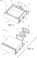
Fig. 1 illustrates a perspective view of an exemplary storage assembly; -
Fig. 1A illustrates a detailed-perspective view of the exemplary storage assembly; -
Fig. 2 illustrates a schematic view of an exemplary drawer assembly according to one or more embodiments; -
Fig. 3 illustrates a perspective view of the exemplary drawer assembly according to one or more embodiments; -
Fig. 4 illustrates an exploded-perspective view of the exemplary drawer assembly depicted inFig. 3 ; -
Fig. 5 illustrates a perspective of a portion of an exemplary drawer assembly according to one or more embodiments; -
Fig. 6 illustrates a partial-perspective-cross-sectional view of the drawer assembly depicted inFig. 5 taken along line 6-6 inFigure 5 ; -
Fig. 6A illustrates a magnified view of area A-A inFig. 6 ; -
Fig. 7 illustrates an exploded view of a portion of the drawer assembly according to one or more embodiments; -
Fig. 8 illustrates a perspective of a portion of an exemplary thermoelectric cooling device for use in one or more of the drawer assemblies; -
Fig. 9 illustrates a schematic-top view of an exemplary drawer assembly; -
Fig. 10 illustrates a schematic-side view of the exemplary drawer assembly depicted inFig. 9 ; -
Fig. 11 illustrates a side-plan view of the drawer assembly depicted inFig. 9 ; -
Fig. 12 illustrates a partial-perspective view of the drawer assembly depicted inFig. 11 ; -
Fig. 13 illustrates a top-plan view of the drawer assembly depicted inFig. 11 ; -
Fig. 14 illustrates a schematic view of a refrigeration system according to one or more embodiments; and -
Fig. 15 illustrates a partial-perspective-cross-sectional view of the drawer assembly depicted inFigs. 11-13 taken along line 15-15 inFigure 13 . - As required, detailed embodiments of the present invention are disclosed herein; however, it is to be understood that the disclosed embodiments are merely exemplary of the invention that may be embodied in various and alternative forms. The figures are not necessarily to scale; some features may be exaggerated or minimized to show details of particular components. Therefore, specific structural and functional details disclosed herein are not to be interpreted as limiting, but merely as a representative basis for teaching one skilled in the art to variously employ the present invention.
- Referring to
Figs. 1 - 1A , astorage structure 10 including abody 12 and a number ofdrawers 14 is provided. Thebody 12 may be formed of non-insulated walls or panels that form a cavity that may receive thedrawers 14. One or more of thedrawers 14 may be arefrigerated drawer assembly 16 that may include aninsulated cabinet 22 disposed in the cavity of thestorage structure 10. Theinsulated cabinet 22 may define a refrigerated compartment and 24 adrawer 26 of thedrawer assembly 16 may be selectively disposed in therefrigerated compartment 24. As an example, thedrawer 26 may move from a retracted or closed position (e.g., see position 27 inFigure 15 ), in which thedrawer 26 is disposed in therefrigerated compartment 24, and a deployed or open position (e.g., see position 29 inFigure 15 ), in which thedrawer 26 is positioned outside of therefrigerated compartment 24 to allow access to a storage space 28 (Fig. 2 ) formed by thedrawer 26. Thedrawer assembly 16 may include a frontinsulated panel 20 that may be fixed to a portion, such as afront wall 32, (Fig. 2 ) of thedrawer 26. Additionally or alternatively, thedrawer assembly 16 may include an aesthetic ordecorative panel 18 that may be fixed to the frontinsulated panel 20. -
Fig. 2 illustrates a schematic view of thedrawer assembly 16 according to one or more embodiments. Thedrawer assembly 16 may include amachine compartment 30 that may be positioned adjacent to theinsulated cabinet 22. In one or more embodiments, themachine compartment 30 may house one or more heat exchangers or components that make up portions of a heat exchange system, including but not limited to a compressor, a fan, athermoelectric device 34 and a drain catchment. -
Fig. 3 illustrates a perspective view of adrawer assembly 100 according to one or more embodiments. Thedrawer assembly 100 includes theinsulated cabinet 22 formed byinsulated side panels 36, a rearinsulated panel 38, and the frontinsulated panel 20. Thethermoelectric device 34 may be fixed to the rearinsulated panel 38 and one or more portions of thethermoelectric device 34 may extend into therefrigerated compartment 24 and themachine compartment 30. As an example, thethermoelectric device 34 may include acold plate 40 that may be disposed in therefrigerated compartment 24 and aheat plate 42 that may be disposed in themachine compartment 30. Thecold plate 40 and theheat plate 42 may operate by the Peltier effect in which an electric current flows through thedevice 34, so that the cool plate decreases in temperature and the hot plate increases in temperature. Theheat plate 42 may be attached to a heat sink to absorb the excess heat from the heat plate. Additionally or alternatively, afirst fan 44 may be fixed to theheat plate 42 and thefirst fan 44 may be configured to move hot air away from therefrigerated compartment 24. -
Fig. 4 illustrates a perspective-exploded view of thedrawer assembly 100. One or more sealing members such aspassthrough grommet 46 and apassthrough gasket 48 may be provided between the rearinsulated panel 38 and thethermoelectric device 34. As an example, thepassthrough gasket 48 may be formed of one or more polymeric materials such as dynamically vulcanized polymer alloy composed of cured EPDM (ethylene propylene diene monomer) rubber (also known as Santoprene), polyvinyl chloride (PVC), or thermoplastic elastomer (TPE), or other material(s) as required. -
Fig. 5 illustrates a perspective view of a portion of thedrawer assembly 100. For purposes of clarity, thedrawer 26 is not illustrated. In one or more embodiments, thethermoelectric device 34 may be fixed to the rearinsulated panel 38 by one ormore straps 56 that may be fixed, such as fastened, to the rearinsulated panel 38. A bottom portion of thethermoelectric device 34 may be supported by a portion 50 of thepassthrough grommet 46. The bottom portion 50 of thepassthrough grommet 46 may define an opening that may receive aspout 52 of adrain funnel 54 that may be configured to collect condensation from thethermoelectric device 34. Thespout 52 may extend into themachine compartment 30 and may be arranged to expel collected condensation to a drain catchment ordrain pan 58 that may stow the collected condensation. - An
insulated cabinet gasket 62 may be fixed to front portions of theinsulated side panels 36 and insulated top andbottom panels insulated side panels 36. When the drawer 26 (not illustrated) is in the retracted or closed position, thecabinet gasket 62 may surround an outer periphery of the frontinsulated panel 20. Theinsulated cabinet gasket 62 may be formed by one or more plastic or polymeric materials including but not limited to a thermoplastic elastomer material. One or more vents such as anair grille 68 may be fixed to a front portion of thedrain pan 58. Theair grille 68 may be configured to permit air flow into thedrain pan 58 to prevent water or fluid held in thedrain pan 58 from being stagnate. As another example, theair grille 68 may be configured to provide an outlet path in which heated air from themachine compartment 30, or thehot plate 42, or both may travel through. - One or more guides such as glide rails 60 may be fixed to one or more of the
insulated side panels 36 and thedrawer 26 may be fixed to a moveable portion of the glide rails so that the drawer may move, after application of a required force applied to the drawer, between the deployed or open position and the retracted or closed position. -
Fig. 6 illustrates a partial cross-sectional view of theinsulated drawer assembly 100. The insulated panels, including the insulatedtop panel 64 and theinsulated bottom panel 66, may each be formed by an inner member such as aliner 70 and an outer member such as awrapper 72 that may collectively form an insulatingcavity 74 in which one or moreinsulating materials 76 may be disposed. It is generally contemplated that the insulation materials may be a glass-type material, a carbon-based powder, silicon oxide-based materials, fumed silica insulating gasses, and other insulation as required. Theinsulation materials 76 substantially fill the insulatingcavity 74 forming a substantially continuous layer between theliner 70 and thewrapper 72. In one or more embodiments, theinsulated cabinet gasket 62 may be fixed to aninner gasket 78 that may be fixed to thewrapper 72 of the insulatedtop panel 64. A bottom portion of theinner gasket 78 may be fixed to theliner 70 of theinsulated bottom panel 66. Theinner gasket 78 may define an opening and theinsulated cabinet gasket 62 may be fixed to theinner gasket 78. - The insulated panels may be formed by creating or pulling a vacuum through the
liner 70 and thewrapper 72 and theinsulation material 76 disposed therebetween. This process removes air between theliner 70 and thewrapper 72 that may otherwise permit cold air to escape and hot air to enter in the refrigerated compartment. Thepassthrough grommet 46,passthrough gasket 48, andinner gasket 78, theliner 70, andwrapper 72 may be collectively configured to provide a sealed vacuum insulated structure for each of the insulated panels. -
Fig. 6A illustrates a detailed magnified view taken of area A-A inFig. 6 . As stated above, the insulatedtop panel 64 may be formed of theliner 70 and thewrapper 72. A rear portion of theliner 70 may include aliner flange 80 and a rear portion of thewrapper 72 may include awrapper flange 82. Thepassthrough grommet 46 may include a main body portion 84 and alip 86 that may extend from the main body portion 84 towards the frontinsulated panel 20. Theliner flange 80 may be disposed on thelip 86 to sandwich thelip 86 to the thermoelectric device 34 (e.g., theliner flange 80 may force thelip 86 into contact with thethermoelectric device 34. More specifically, theliner flange 80 may sandwich the lip 86 (e.g., force the lip into contact with) to thecold plate 40 of thethermoelectric device 34. As an example, thepassthrough grommet 46 may be formed of an elastic material such as an elastomer so that thelip 86 compresses when theliner flange 80 is disposed on thelip 86. - In one or more embodiments, the
passthrough gasket 48 may include ahorizontal wall 88, a firstvertical wall 90, and a secondvertical wall 92. Aprotrusion 94 may extend from thehorizontal wall 88 and theprotrusion 94 may be spaced apart from the firstvertical wall 90 to form a space configured to receive theflange 82 of thewrapper 72 to fix the position of thewrapper 72 with respect to thethermoelectric device 34. The secondvertical wall 92 may be fixed to theliner flange 80 by an adhesive such as anadhesive tape 96. Theliner flange 80 may be fixed to the secondvertical wall 92 prior to installing theinsulation materials 76 or more specifically prior to applying a vacuum to install theinsulation materials 76. -
Fig. 7 illustrates an exploded view of thethermoelectric device 34 and thestraps 56. As stated above, thefirst fan 44 may be fixed to a portion of thethermoelectric device 34 such as theheat plate 42. Thestraps 56 may engage an outer periphery of thecold plate 40 so that thethermoelectric device 34 is fixed to a portion of theinsulated cabinet 22. -
Fig. 8 illustrates a perspective view of an exemplarythermoelectric device 98 according to one or more embodiments. Thethermoelectric device 98 may include thecold plate 40 and aheat plate 102, where theheat plate 102 is relatively wider than thecold plate 40. In one or more embodiments, asecond fan 104 may be fixed to thecold plate 40. Thethermoelectric device 98 may be fixed to the rearinsulated panel 38 in a manner similarly described and illustrated in reference toFigs. 6 and6A . -
Fig. 9 illustrates a top-schematic view of anexemplary drawer assembly 106. Thedrawer assembly 106 may include arefrigeration system 109 that may be provided with anevaporator 108. Generally, theevaporator 108 may be disposed between the rearinsulated panel 38 and the drawer 26 (also shown inFig. 15 ). In one or more embodiments, theevaporator 108 may be a roll-bond evaporator. The roll-bond evaporator 108 may be a plate cooler formed in such a way that a refrigerant tube, through which a refrigerant flows, is provided in an aluminum plate. The roll-bond evaporator 108 may include a refrigerant inlet through which a refrigerant is introduced and a refrigerant outlet through which the refrigerant is discharged. The roll-bond evaporator 108 may generate cold air to cool theinsulated cabinet 22. - The
drawer assembly 106 may include a base 116 that may support theinsulated cabinet 22 and may form portions of themachine compartment 30 disposed rearward of theinsulated cabinet 22. The base 116 may be configured to support acompressor 110, adrain pan 112, and afan 114 each of which constitute portions of therefrigerator system 109. -
Fig. 10 illustrates a schematic-side view of thedrawer assembly 106 andFig. 11 illustrates a side-plan view of thedrawer assembly 106. In one or more embodiments, therefrigeration system 109 may include acondenser 118 that may be disposed between the base 116 and thedrawer 26. As will be described in greater detail below, thecondenser 118 may form a cold air supply path and a warm air return bath for thedrawer assembly 106. Therefrigeration system 109 may include acontroller 122 that may be operatively coupled to thecompressor 110 and thefan 114. As an example, thecontroller 122 may be configured to actuate one or more components of therefrigeration system 109 in response to input from a sensor e.g., a temperature sensor, drawer sensor, or any other sensor. - The
controller 122 may include a memory provided with stored instructions that may be used to actuate thecompressor 110, thefan 114 or other components of therefrigeration system 109, as required. As an example, thecontroller 122 may be configured to control the activation, duty cycle, and operation of thecompressor 110. - The
compressor 110 is configured to circulate and change refrigerant from a liquid state to a gas state by routing the refrigerant through theevaporator 108 so that the refrigerant undergoes an evaporation process in order to cool the air within the refrigeratedspace 24. During the evaporation process, heat is transferred to the refrigerant. After evaporating, thecompressor 110 increases the pressure, an in turn, the temperature of the refrigerant. The gas refrigerant is then routed to thecondenser 118 so that it is condensed into a liquid and the excess heat is rejected to the ambient surroundings. The process then repeats. -
Fig. 12 illustrates a top-perspective view of thedrawer assembly 106. As previously mentioned, theinsulated cabinet 22 forms arefrigerated space 24 in which the drawer 26 (not illustrated) is stowed. The rearinsulated wall 38 of theinsulated cabinet 22 may be adjacent to themachine compartment 30. Theevaporator 108 may be fixed to the rearinsulated wall 38 of the insulated cabinet. In order to properly cool therefrigerated space 24, heat needs to be rejected to the ambient surroundings. This is accomplished by drawing air into themachine compartment 30 as well as the space between thedrawer 26 and thebase 116, across thecompressor 110 and condenser 118 (Fig. 11 ). Thefan 114 provides the driving force to move air through themachine compartment 30 and the space beneath thedrawer 26 and above the base 116 where thecondenser 118 is located. - The
compressor 110 may be supported by thebase 116 and positioned adjacent to thedrain pain 112 and thefan 114. By positioning thecompressor 110,drain pan 112, and thefan 114 in themachine compartment 30 and by positioning theevaporator 108 on the rearinsulated panel 38 and thecondenser 118 beneath thedrawer 26, relatively little space is required from therefrigeration system 109. By minimizing space required for therefrigeration system 109 permits a largerrefrigerated space 24. -
Fig. 13 illustrates a top view of a portion of thedrawer assembly 106. As mentioned above, thecompressor 110 anddrain pan 112 may each be disposed on thebase 116 behind the rearinsulated panel 38 of theinsulated cabinet 22. In one or more embodiments, thecontroller 122 may be fixed to the rearinsulated panel 38. -
Fig. 14 illustrates a top-schematic view of therefrigeration system 109. The base 116 may include afirst side 116a and asecond side 116b. Thecompressor 110 may be arranged on thefirst side 116a of thebase 116. Whereas thedrain pan 112 andcondenser 118 may be disposed on thesecond side 116b of thebase 116. The arrangement of thecompressor 110 andcondenser 118 may form a warmair return pathway 126 and acold air supply 128. Warm air may be directed from the compressor along the warmair return pathway 126 through theair grille 68. Cold air may be directed from ambient surroundings, through the air grille 68 (Fig. 5 ), past thecondenser 118 to thedrain pan 112. In one or more embodiments, a sound barrier such assound insulation 124 may positioned adjacent to thecondenser 118 and configured to mitigate noise generated by thecondenser 118. -
Fig. 15 illustrates a cross-sectional view of thedrawer assembly 106. In one or more embodiments, thecontroller 122 may be fixed to theouter wrapper 72 bybracket 130. Thebracket 130 may be L-shaped including a first leg and a second leg. The second leg may include an aperture and a portion of thecontroller 122 may extend through the aperture so that thecontroller 122 is fixed to the L-shapedbracket 130. As an example, theliner 70 may include arear wall 132 that may extend in a vertical direction. Theevaporator 108 may be fixed to therear wall 132. Thedrawer 26 may include sidewalls 136 (only one of which is shown) that are connected to arear wall 134 and abottom wall 138. Because thedrawer 26 is disposed in the refrigeratedspace 24, thesidewalls 136,rear wall 134 and thebottom wall 138 may be formed of a non-insulative material to permit refrigerated air to flow into thestorage space 28 formed by thedrawer 26.
Claims (15)
- A storage assembly (10) comprising:a vacuum insulated cabinet (22) formed by a number of insulated panels (20, 36, 38, 64, 66);a refrigeration system (109), wherein the vacuum insulated cabinet (22) and the refrigeration system (109) collectively form a refrigerated compartment (24); anda drawer (26) configured to move between an open position (29), in which an interior portion of the drawer (26) is accessible, and a closed position (27), in which the drawer (26) is disposed in the refrigerated compartment (24) and the interior portion of the drawer (26) is inaccessible, wherein the refrigeration system (109) includes a first heat exchanger (40, 108), disposed between the drawer (26) and a rear portion of the insulated cabinet (22), and a second heat exchanger (42, 118) disposed in a machine compartment (30) adjacent to the refrigerated compartment (24).
- The storage assembly (10) of claim 1, further comprising:a first sealing member (46) lying along an outer periphery of the second heat exchanger (42, 118); anda second sealing member (48) lying along the first sealing member (46), wherein a first insulated panel (38) of the number of insulated panels (20, 36, 38, 64, and 66) forces the second sealing member (48) into contact with the first sealing member (46).
- The storage assembly (10) of claim 2, wherein the second sealing member (48) includes a first vertical leg (90), a second vertical leg (92), and a horizontal leg (88) extending therebetween, and the first insulated panel (38) includes a liner sheet (70) fixed to the second leg (92) of the second sealing member (48).
- The storage assembly (10) of claim 2 or claim 3, wherein the first insulated panel (38) includes a wrapper sheet (72) and a portion of the wrapper sheet (72) lies along the first leg (90).
- The storage assembly (10) of anyone of claims 2 to 4, further comprising an adhesive (96) disposed between and fixing the liner sheet (70) to the second leg (92) of the second sealing member (48).
- The storage assembly (10) of anyone of claims 2 to 5, wherein the first sealing member (46) includes a lip (86) disposed between the first heat exchanger (40, 108) and the second leg (92) of the second sealing member (48).
- The storage assembly (10) of claim 6, wherein the lip (86) is formed of an elastomeric material, and the second leg (92) of the second sealing member (48) and the liner sheet (70) are positioned to contact the lip (86) such that the lip (86) elastically deforms from a nominal position.
- The storage assembly (10) of anyone of the previous claims, further comprising a base (116) disposed beneath the vacuum insulated cabinet (22) and partially defining the machine compartment (30).
- The storage assembly (10) of anyone of the previous claims, wherein the first heat exchanger (40, 108) is a thermoelectric cooling plate configured to refrigerate the refrigerated compartment (24).
- The storage assembly (10) of anyone of the previous claims, wherein the second heat exchanger (42, 118) is a thermoelectric heating plate configured to dissipate heat away from the refrigerated compartment (24).
- The storage assembly (10) of anyone of claims 9 and 10, wherein a first fan (44) is fixed to the thermoelectric cooling plate and is configured to direct air towards the drawer (26) and wherein a second fan (104) is fixed to the thermoelectric heating plate and is configured to direct air away from the insulated cabinet (22).
- The storage assembly (10) of anyone of the previous claims, wherein the rear portion is formed by a rear insulated panel (38) of the number of insulated panels (20, 36, 38, 64, 66) and wherein the rear insulated panel (38) defines an aperture configured to receive at least one of the first heat exchanger (40, 108) or the second heat exchanger (42, 118).
- The storage assembly (10) of anyone of the previous claims, wherein the first heat exchanger (40, 108) is a first thermoelectric device and the second heat exchanger (42, 118) is a second thermoelectric device.
- The storage assembly (10) of claim 13, further comprising a sealing member (46, 48) disposed along and between an outer periphery of at least one of the first thermoelectric device or the second thermoelectric device and an inner periphery of an aperture formed by a rear insulated panel (38) of the number of insulated panels (20, 36, 38, 64, 66).
- The storage assembly (10) of claim 13 or claim 14, further comprising a drain catchment assembly including a funnel (54) and a spout (52), wherein the funnel (54) is disposed beneath the first thermoelectric device and the spout (52) extends through at least one of the rear insulated panel (38) or the sealing member (46, 48) and terminates in the machine compartment (30).
Applications Claiming Priority (3)
| Application Number | Priority Date | Filing Date | Title |
|---|---|---|---|
| US202163286322P | 2021-12-06 | 2021-12-06 | |
| US17/959,772 US20230175764A1 (en) | 2021-12-06 | 2022-10-04 | Refrigerated storage structure |
| EP22203943.0A EP4191170A3 (en) | 2021-12-06 | 2022-10-26 | Refrigerated storage structure |
Related Parent Applications (1)
| Application Number | Title | Priority Date | Filing Date |
|---|---|---|---|
| EP22203943.0A Division EP4191170A3 (en) | 2021-12-06 | 2022-10-26 | Refrigerated storage structure |
Publications (2)
| Publication Number | Publication Date |
|---|---|
| EP4332479A2 true EP4332479A2 (en) | 2024-03-06 |
| EP4332479A3 EP4332479A3 (en) | 2024-05-15 |
Family
ID=84044091
Family Applications (2)
| Application Number | Title | Priority Date | Filing Date |
|---|---|---|---|
| EP24153085.6A Withdrawn EP4332479A3 (en) | 2021-12-06 | 2022-10-26 | Refrigerated storage structure |
| EP22203943.0A Withdrawn EP4191170A3 (en) | 2021-12-06 | 2022-10-26 | Refrigerated storage structure |
Family Applications After (1)
| Application Number | Title | Priority Date | Filing Date |
|---|---|---|---|
| EP22203943.0A Withdrawn EP4191170A3 (en) | 2021-12-06 | 2022-10-26 | Refrigerated storage structure |
Country Status (2)
| Country | Link |
|---|---|
| US (1) | US20230175764A1 (en) |
| EP (2) | EP4332479A3 (en) |
Families Citing this family (3)
| Publication number | Priority date | Publication date | Assignee | Title |
|---|---|---|---|---|
| EP4050287B1 (en) * | 2021-02-26 | 2025-09-17 | Dometic Sweden AB | Wine cellar drawer, wine cabinet with it and kitchen cabinet with such wine cellar drawer |
| USD1087181S1 (en) | 2021-02-26 | 2025-08-05 | Dometic Sweden Ab | Refrigerated drawer |
| US20240015931A1 (en) * | 2022-07-05 | 2024-01-11 | Corning Research & Development Corporation | Heat exchanger and small cell radio node incorporating the same |
Family Cites Families (11)
| Publication number | Priority date | Publication date | Assignee | Title |
|---|---|---|---|---|
| IT207399Z2 (en) * | 1985-11-22 | 1988-01-18 | Ilpea Spa | FRAME IN RIGID MATERIAL SUITABLE FOR DELIMITING THE EDGES OF THE FURNITURE OF A HORIZONTAL FREEZER. |
| CN1140431A (en) * | 1994-01-12 | 1997-01-15 | 海洋工程国际公司 | Cabinet of thermoelectric refrigerator and its realization method |
| US6460956B1 (en) * | 1998-06-12 | 2002-10-08 | Maytag Corporation | Shelf mounting support arrangement |
| US6370882B1 (en) * | 2000-09-08 | 2002-04-16 | Distinctive Appliances, Inc. | Temperature controlled compartment apparatus |
| US6484512B1 (en) * | 2001-06-08 | 2002-11-26 | Maytag Corporation | Thermoelectric temperature controlled drawer assembly |
| KR100455924B1 (en) * | 2002-01-31 | 2004-11-06 | 삼성전자주식회사 | Cooling and Heating Apparatus Utlizing Thermoelectric Module |
| PL1586253T3 (en) * | 2004-04-13 | 2010-11-30 | Whirlpool Co | Drawer appliance |
| KR102309117B1 (en) * | 2017-03-21 | 2021-10-06 | 엘지전자 주식회사 | Refrigerator |
| KR102330783B1 (en) * | 2017-06-01 | 2021-11-25 | 엘지전자 주식회사 | A Refrigerator |
| KR102225075B1 (en) * | 2020-09-23 | 2021-03-09 | 주식회사 윈텍 | Drawer-type built-in refrigerator |
| CN112546393A (en) * | 2020-12-11 | 2021-03-26 | 珠海格力电器股份有限公司 | Environment management apparatus and control method thereof |
-
2022
- 2022-10-04 US US17/959,772 patent/US20230175764A1/en not_active Abandoned
- 2022-10-26 EP EP24153085.6A patent/EP4332479A3/en not_active Withdrawn
- 2022-10-26 EP EP22203943.0A patent/EP4191170A3/en not_active Withdrawn
Also Published As
| Publication number | Publication date |
|---|---|
| EP4191170A2 (en) | 2023-06-07 |
| EP4191170A3 (en) | 2023-07-05 |
| EP4332479A3 (en) | 2024-05-15 |
| US20230175764A1 (en) | 2023-06-08 |
Similar Documents
| Publication | Publication Date | Title |
|---|---|---|
| EP4191170A2 (en) | Refrigerated storage structure | |
| US20200326108A1 (en) | Refrigerator | |
| EP1642070B1 (en) | Refrigerator | |
| JP2008190815A (en) | Refrigerator | |
| RU2765915C2 (en) | Vacuum adiabatic body, cooling or heating apparatus and vehicle | |
| JP2010038528A (en) | refrigerator | |
| CN103975209B (en) | Freezer | |
| KR20180080649A (en) | A Refrigerator Having Deeply Low Temperature Freezer | |
| US12130066B2 (en) | Refrigerated compartment air distribution assembly | |
| CN106321964B (en) | Fixation member and equipment with the fixation member | |
| US20200191451A1 (en) | Thermally Insulated Receptacle | |
| CN113396307B (en) | Refrigerator with direct cooling door inner chamber | |
| RU2702197C1 (en) | Refrigerator | |
| JP2008267654A (en) | Refrigerator | |
| JP2018096598A (en) | refrigerator | |
| JP2000320942A (en) | Refrigerator | |
| US7216493B2 (en) | Refrigerator methods and apparatus | |
| JP2018096597A (en) | refrigerator | |
| KR20180095280A (en) | Refrigerating or warming apparatus, and vehicle | |
| JP2012098010A (en) | Cooling storage | |
| CN119103779A (en) | Refrigeration equipment having refrigerant and water lines extending through a common penetration of a vacuum insulation structure | |
| JP4118210B2 (en) | refrigerator | |
| JP2008202882A (en) | Refrigerator | |
| JP2008180450A (en) | Refrigerator | |
| CN112005063B (en) | Refrigerator with heatable interior |
Legal Events
| Date | Code | Title | Description |
|---|---|---|---|
| PUAI | Public reference made under article 153(3) epc to a published international application that has entered the european phase |
Free format text: ORIGINAL CODE: 0009012 |
|
| STAA | Information on the status of an ep patent application or granted ep patent |
Free format text: STATUS: THE APPLICATION HAS BEEN PUBLISHED |
|
| AC | Divisional application: reference to earlier application |
Ref document number: 4191170 Country of ref document: EP Kind code of ref document: P |
|
| AK | Designated contracting states |
Kind code of ref document: A2 Designated state(s): AL AT BE BG CH CY CZ DE DK EE ES FI FR GB GR HR HU IE IS IT LI LT LU LV MC ME MK MT NL NO PL PT RO RS SE SI SK SM TR |
|
| PUAL | Search report despatched |
Free format text: ORIGINAL CODE: 0009013 |
|
| AK | Designated contracting states |
Kind code of ref document: A3 Designated state(s): AL AT BE BG CH CY CZ DE DK EE ES FI FR GB GR HR HU IE IS IT LI LT LU LV MC ME MK MT NL NO PL PT RO RS SE SI SK SM TR |
|
| RIC1 | Information provided on ipc code assigned before grant |
Ipc: F25D 23/08 20060101ALN20240408BHEP Ipc: F25D 23/00 20060101ALI20240408BHEP Ipc: F25D 25/02 20060101AFI20240408BHEP |
|
| P01 | Opt-out of the competence of the unified patent court (upc) registered |
Effective date: 20240517 |
|
| STAA | Information on the status of an ep patent application or granted ep patent |
Free format text: STATUS: THE APPLICATION IS DEEMED TO BE WITHDRAWN |
|
| 18D | Application deemed to be withdrawn |
Effective date: 20241116 |