EP4332366A1 - Fuel pump - Google Patents
Fuel pump Download PDFInfo
- Publication number
- EP4332366A1 EP4332366A1 EP22837410.4A EP22837410A EP4332366A1 EP 4332366 A1 EP4332366 A1 EP 4332366A1 EP 22837410 A EP22837410 A EP 22837410A EP 4332366 A1 EP4332366 A1 EP 4332366A1
- Authority
- EP
- European Patent Office
- Prior art keywords
- fuel
- channels
- discharge
- suction
- pump
- Prior art date
- Legal status (The legal status is an assumption and is not a legal conclusion. Google has not performed a legal analysis and makes no representation as to the accuracy of the status listed.)
- Pending
Links
Images




Classifications
-
- F—MECHANICAL ENGINEERING; LIGHTING; HEATING; WEAPONS; BLASTING
- F02—COMBUSTION ENGINES; HOT-GAS OR COMBUSTION-PRODUCT ENGINE PLANTS
- F02M—SUPPLYING COMBUSTION ENGINES IN GENERAL WITH COMBUSTIBLE MIXTURES OR CONSTITUENTS THEREOF
- F02M59/00—Pumps specially adapted for fuel-injection and not provided for in groups F02M39/00 -F02M57/00, e.g. rotary cylinder-block type of pumps
- F02M59/02—Pumps specially adapted for fuel-injection and not provided for in groups F02M39/00 -F02M57/00, e.g. rotary cylinder-block type of pumps of reciprocating-piston or reciprocating-cylinder type
- F02M59/04—Pumps specially adapted for fuel-injection and not provided for in groups F02M39/00 -F02M57/00, e.g. rotary cylinder-block type of pumps of reciprocating-piston or reciprocating-cylinder type characterised by special arrangement of cylinders with respect to piston-driving shaft, e.g. arranged parallel to that shaft or swash-plate type pumps
-
- F—MECHANICAL ENGINEERING; LIGHTING; HEATING; WEAPONS; BLASTING
- F04—POSITIVE - DISPLACEMENT MACHINES FOR LIQUIDS; PUMPS FOR LIQUIDS OR ELASTIC FLUIDS
- F04B—POSITIVE-DISPLACEMENT MACHINES FOR LIQUIDS; PUMPS
- F04B1/00—Multi-cylinder machines or pumps characterised by number or arrangement of cylinders
- F04B1/04—Multi-cylinder machines or pumps characterised by number or arrangement of cylinders having cylinders in star- or fan-arrangement
- F04B1/0404—Details or component parts
- F04B1/0421—Cylinders
-
- F—MECHANICAL ENGINEERING; LIGHTING; HEATING; WEAPONS; BLASTING
- F02—COMBUSTION ENGINES; HOT-GAS OR COMBUSTION-PRODUCT ENGINE PLANTS
- F02M—SUPPLYING COMBUSTION ENGINES IN GENERAL WITH COMBUSTIBLE MIXTURES OR CONSTITUENTS THEREOF
- F02M37/00—Apparatus or systems for feeding liquid fuel from storage containers to carburettors or fuel-injection apparatus; Arrangements for purifying liquid fuel specially adapted for, or arranged on, internal-combustion engines
- F02M37/0011—Constructional details; Manufacturing or assembly of elements of fuel systems; Materials therefor
- F02M37/0023—Valves in the fuel supply and return system
-
- F—MECHANICAL ENGINEERING; LIGHTING; HEATING; WEAPONS; BLASTING
- F02—COMBUSTION ENGINES; HOT-GAS OR COMBUSTION-PRODUCT ENGINE PLANTS
- F02M—SUPPLYING COMBUSTION ENGINES IN GENERAL WITH COMBUSTIBLE MIXTURES OR CONSTITUENTS THEREOF
- F02M37/00—Apparatus or systems for feeding liquid fuel from storage containers to carburettors or fuel-injection apparatus; Arrangements for purifying liquid fuel specially adapted for, or arranged on, internal-combustion engines
- F02M37/04—Feeding by means of driven pumps
- F02M37/043—Arrangements for driving reciprocating piston-type pumps
-
- F—MECHANICAL ENGINEERING; LIGHTING; HEATING; WEAPONS; BLASTING
- F02—COMBUSTION ENGINES; HOT-GAS OR COMBUSTION-PRODUCT ENGINE PLANTS
- F02M—SUPPLYING COMBUSTION ENGINES IN GENERAL WITH COMBUSTIBLE MIXTURES OR CONSTITUENTS THEREOF
- F02M55/00—Fuel-injection apparatus characterised by their fuel conduits or their venting means; Arrangements of conduits between fuel tank and pump F02M37/00
- F02M55/02—Conduits between injection pumps and injectors, e.g. conduits between pump and common-rail or conduits between common-rail and injectors
- F02M55/025—Common rails
-
- F—MECHANICAL ENGINEERING; LIGHTING; HEATING; WEAPONS; BLASTING
- F02—COMBUSTION ENGINES; HOT-GAS OR COMBUSTION-PRODUCT ENGINE PLANTS
- F02M—SUPPLYING COMBUSTION ENGINES IN GENERAL WITH COMBUSTIBLE MIXTURES OR CONSTITUENTS THEREOF
- F02M59/00—Pumps specially adapted for fuel-injection and not provided for in groups F02M39/00 -F02M57/00, e.g. rotary cylinder-block type of pumps
- F02M59/02—Pumps specially adapted for fuel-injection and not provided for in groups F02M39/00 -F02M57/00, e.g. rotary cylinder-block type of pumps of reciprocating-piston or reciprocating-cylinder type
- F02M59/08—Pumps specially adapted for fuel-injection and not provided for in groups F02M39/00 -F02M57/00, e.g. rotary cylinder-block type of pumps of reciprocating-piston or reciprocating-cylinder type characterised by two or more pumping elements with conjoint outlet or several pumping elements feeding one engine cylinder
-
- F—MECHANICAL ENGINEERING; LIGHTING; HEATING; WEAPONS; BLASTING
- F02—COMBUSTION ENGINES; HOT-GAS OR COMBUSTION-PRODUCT ENGINE PLANTS
- F02M—SUPPLYING COMBUSTION ENGINES IN GENERAL WITH COMBUSTIBLE MIXTURES OR CONSTITUENTS THEREOF
- F02M59/00—Pumps specially adapted for fuel-injection and not provided for in groups F02M39/00 -F02M57/00, e.g. rotary cylinder-block type of pumps
- F02M59/02—Pumps specially adapted for fuel-injection and not provided for in groups F02M39/00 -F02M57/00, e.g. rotary cylinder-block type of pumps of reciprocating-piston or reciprocating-cylinder type
- F02M59/10—Pumps specially adapted for fuel-injection and not provided for in groups F02M39/00 -F02M57/00, e.g. rotary cylinder-block type of pumps of reciprocating-piston or reciprocating-cylinder type characterised by the piston-drive
- F02M59/102—Mechanical drive, e.g. tappets or cams
-
- F—MECHANICAL ENGINEERING; LIGHTING; HEATING; WEAPONS; BLASTING
- F02—COMBUSTION ENGINES; HOT-GAS OR COMBUSTION-PRODUCT ENGINE PLANTS
- F02M—SUPPLYING COMBUSTION ENGINES IN GENERAL WITH COMBUSTIBLE MIXTURES OR CONSTITUENTS THEREOF
- F02M59/00—Pumps specially adapted for fuel-injection and not provided for in groups F02M39/00 -F02M57/00, e.g. rotary cylinder-block type of pumps
- F02M59/44—Details, components parts, or accessories not provided for in, or of interest apart from, the apparatus of groups F02M59/02 - F02M59/42; Pumps having transducers, e.g. to measure displacement of pump rack or piston
-
- F—MECHANICAL ENGINEERING; LIGHTING; HEATING; WEAPONS; BLASTING
- F02—COMBUSTION ENGINES; HOT-GAS OR COMBUSTION-PRODUCT ENGINE PLANTS
- F02M—SUPPLYING COMBUSTION ENGINES IN GENERAL WITH COMBUSTIBLE MIXTURES OR CONSTITUENTS THEREOF
- F02M59/00—Pumps specially adapted for fuel-injection and not provided for in groups F02M39/00 -F02M57/00, e.g. rotary cylinder-block type of pumps
- F02M59/44—Details, components parts, or accessories not provided for in, or of interest apart from, the apparatus of groups F02M59/02 - F02M59/42; Pumps having transducers, e.g. to measure displacement of pump rack or piston
- F02M59/46—Valves
- F02M59/462—Delivery valves
-
- F—MECHANICAL ENGINEERING; LIGHTING; HEATING; WEAPONS; BLASTING
- F04—POSITIVE - DISPLACEMENT MACHINES FOR LIQUIDS; PUMPS FOR LIQUIDS OR ELASTIC FLUIDS
- F04B—POSITIVE-DISPLACEMENT MACHINES FOR LIQUIDS; PUMPS
- F04B1/00—Multi-cylinder machines or pumps characterised by number or arrangement of cylinders
- F04B1/04—Multi-cylinder machines or pumps characterised by number or arrangement of cylinders having cylinders in star- or fan-arrangement
- F04B1/0404—Details or component parts
- F04B1/0452—Distribution members, e.g. valves
-
- F—MECHANICAL ENGINEERING; LIGHTING; HEATING; WEAPONS; BLASTING
- F04—POSITIVE - DISPLACEMENT MACHINES FOR LIQUIDS; PUMPS FOR LIQUIDS OR ELASTIC FLUIDS
- F04B—POSITIVE-DISPLACEMENT MACHINES FOR LIQUIDS; PUMPS
- F04B53/00—Component parts, details or accessories not provided for in, or of interest apart from, groups F04B1/00 - F04B23/00 or F04B39/00 - F04B47/00
- F04B53/14—Pistons, piston-rods or piston-rod connections
-
- F—MECHANICAL ENGINEERING; LIGHTING; HEATING; WEAPONS; BLASTING
- F04—POSITIVE - DISPLACEMENT MACHINES FOR LIQUIDS; PUMPS FOR LIQUIDS OR ELASTIC FLUIDS
- F04B—POSITIVE-DISPLACEMENT MACHINES FOR LIQUIDS; PUMPS
- F04B53/00—Component parts, details or accessories not provided for in, or of interest apart from, groups F04B1/00 - F04B23/00 or F04B39/00 - F04B47/00
- F04B53/16—Casings; Cylinders; Cylinder liners or heads; Fluid connections
-
- F—MECHANICAL ENGINEERING; LIGHTING; HEATING; WEAPONS; BLASTING
- F04—POSITIVE - DISPLACEMENT MACHINES FOR LIQUIDS; PUMPS FOR LIQUIDS OR ELASTIC FLUIDS
- F04B—POSITIVE-DISPLACEMENT MACHINES FOR LIQUIDS; PUMPS
- F04B1/00—Multi-cylinder machines or pumps characterised by number or arrangement of cylinders
- F04B1/04—Multi-cylinder machines or pumps characterised by number or arrangement of cylinders having cylinders in star- or fan-arrangement
- F04B1/0404—Details or component parts
- F04B1/0452—Distribution members, e.g. valves
- F04B1/0456—Cylindrical
-
- F—MECHANICAL ENGINEERING; LIGHTING; HEATING; WEAPONS; BLASTING
- F04—POSITIVE - DISPLACEMENT MACHINES FOR LIQUIDS; PUMPS FOR LIQUIDS OR ELASTIC FLUIDS
- F04B—POSITIVE-DISPLACEMENT MACHINES FOR LIQUIDS; PUMPS
- F04B1/00—Multi-cylinder machines or pumps characterised by number or arrangement of cylinders
- F04B1/04—Multi-cylinder machines or pumps characterised by number or arrangement of cylinders having cylinders in star- or fan-arrangement
- F04B1/047—Multi-cylinder machines or pumps characterised by number or arrangement of cylinders having cylinders in star- or fan-arrangement with actuating or actuated elements at the outer ends of the cylinders
- F04B1/0474—Multi-cylinder machines or pumps characterised by number or arrangement of cylinders having cylinders in star- or fan-arrangement with actuating or actuated elements at the outer ends of the cylinders with two or more serially arranged radial piston-cylinder units
- F04B1/0476—Multi-cylinder machines or pumps characterised by number or arrangement of cylinders having cylinders in star- or fan-arrangement with actuating or actuated elements at the outer ends of the cylinders with two or more serially arranged radial piston-cylinder units located side-by-side
-
- F—MECHANICAL ENGINEERING; LIGHTING; HEATING; WEAPONS; BLASTING
- F04—POSITIVE - DISPLACEMENT MACHINES FOR LIQUIDS; PUMPS FOR LIQUIDS OR ELASTIC FLUIDS
- F04B—POSITIVE-DISPLACEMENT MACHINES FOR LIQUIDS; PUMPS
- F04B53/00—Component parts, details or accessories not provided for in, or of interest apart from, groups F04B1/00 - F04B23/00 or F04B39/00 - F04B47/00
- F04B53/007—Cylinder heads
-
- F—MECHANICAL ENGINEERING; LIGHTING; HEATING; WEAPONS; BLASTING
- F04—POSITIVE - DISPLACEMENT MACHINES FOR LIQUIDS; PUMPS FOR LIQUIDS OR ELASTIC FLUIDS
- F04B—POSITIVE-DISPLACEMENT MACHINES FOR LIQUIDS; PUMPS
- F04B53/00—Component parts, details or accessories not provided for in, or of interest apart from, groups F04B1/00 - F04B23/00 or F04B39/00 - F04B47/00
- F04B53/22—Arrangements for enabling ready assembly or disassembly
Definitions
- the present disclosure relates to a fuel pump applied to an internal combustion engine.
- a common-rail-type fuel injection device applied to a diesel engine includes a fuel pump, a common rail, and a fuel injector.
- the fuel pump inhales fuel from a fuel tank, pressurizes the fuel, and supplies the fuel to the common rail as high-pressure fuel.
- the common rail holds the high-pressure fuel supplied from the fuel pump at a predetermined pressure.
- the fuel injector injects the high-pressure fuel of the common rail into a combustion chamber of the diesel engine by opening and closing the injector.
- the fuel pump includes plunger barrels, plungers, suction valves, and discharge valves. In a case where the plunger moves inside the plunger barrel in one direction, the suction valve is opened and the fuel is inhaled into the pressurization chamber.
- the fuel in the pressurization chamber is pressurized, and the discharge valve is opened to discharge the high-pressure fuel.
- a fuel pump examples include a fuel pump described in PTL 1 below.
- plungers and plunger barrels are respectively disposed corresponding to a plurality of cams provided on a cam shaft. That is, the fuel pump is configured by disposing plunger units in which a plunger, a suction valve, and a discharge valve are mounted on a plunger barrel at an interval in an axial direction of a cam shaft and connecting the plunger units to each other. For this reason, one plunger unit becomes large, and the plunger barrel has a complicated shape. As a result, there is a problem that processing is difficult and a processing cost increases.
- each fuel discharge unit is connected to the common rail via each connection pipe.
- a connection structure between the plunger unit and the common rail becomes complicated, and pressure pulsation occurs at different timings in each connection pipe. As a result, this will adversely affect a fuel discharge amount, a fuel discharge pressure, and the like.
- the present disclosure has been made to solve the above-described problem, and an object of the present disclosure is to provide a fuel pump that suppresses occurrence of fuel pressure pulsation while simplifying a structure and reducing a processing cost.
- a fuel pump including: a pump head; a plurality of plunger barrel units in which a plurality of plungers are movably supported, which are provided with a plurality of pressurization chambers for pressurizing fuel by movement of the plungers, and which are mounted in parallel on the pump head; a plurality of discharge valve units that are disposed in a plurality of fuel discharge channels provided in the pump head so as to communicate with the plurality of pressurization chambers; a plurality of suction valve units that are disposed in a plurality of fuel suction channels provided in the pump head so as to communicate with the plurality of pressurization chambers; a fuel-discharge-side communication channel that communicates with the plurality of fuel discharge channels; and a connector that supplies the fuel of the fuel-discharge-side communication channel to outside.
- the fuel pump of the present disclosure it is possible to simplify a structure and reduce a processing cost, and it is possible to suppress occurrence of fuel pressure pulsation.
- the present disclosure is not limited by the embodiment, and in a case where there are a plurality of embodiments, the present disclosure also includes a configuration in which the respective embodiments are combined with each other.
- components in the embodiment include components that can be easily assumed by those skilled in the art, components that are substantially the same, or components that fall within an equivalent range.
- Fig. 1 is a schematic configuration diagram illustrating a fuel injection device of the present embodiment.
- the fuel injection device 10 is mounted on a diesel engine (internal combustion engine).
- the fuel injection device 10 includes a fuel pump 11, a common rail 12, and a plurality of fuel injectors 13.
- a fuel tank 14 is connected to the fuel pump 11 via a fuel line L11.
- the fuel pump 11 inhales the fuel stored in the fuel tank 14 from the fuel line L11, and pressurizes the fuel to generate high-pressure fuel.
- the common rail 12 is connected to the fuel pump 11 via a high-pressure fuel line L12.
- the common rail 12 adjusts the high-pressure fuel supplied from the fuel pump 11 to a predetermined pressure.
- the fuel injectors 13 are respectively connected to the common rail 12 via a plurality of (in the present embodiment, four) fuel supply lines L13.
- the fuel injector 13 injects the high-pressure fuel of the common rail 12 into each cylinder (combustion chamber) of the diesel engine by opening and closing the injector.
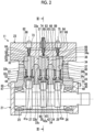
- Fig. 2 is a vertical sectional view illustrating the fuel pump of the present embodiment
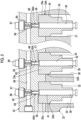
- Fig. 3 is a sectional view taken along a III-III line of Fig. 2 illustrating a vertical section of the fuel pump.
- the fuel pump to be described below has a type in which three plungers are disposed. On the other hand, the number of the plungers is not limited thereto.
- a housing of the fuel pump 11 is configured by bolt-fastening a retainer 21, a pump casing 22, and a pump head 23.
- a cam shaft 24 is disposed inside the pump casing 22.
- Each end portion of the cam shaft 24 in an axial direction is rotatably supported by the retainer 21 by bearings 25 and 26.
- One end portion of the cam shaft 24 in the axial direction protrudes to the outside of the retainer 21, and a driving force is input from the diesel engine.
- a plurality of (in the present embodiment, three) cams 27, 28, and 29 are provided at intervals in the axial direction.
- the cams 27, 28, and 29 have different phases in a circumferential direction.
- the retainer 21 is fastened to the pump casing 22 by a plurality of bolts 30.
- the plurality of bolts 30 penetrate the retainer 21, and tip portions of the plurality of bolts 30 are screwed to the pump casing 22.
- the pump head 23 is fastened to the pump casing 22 by a plurality of bolts 31.
- the plurality of bolts 31 penetrate the pump head 23, and are screwed into the pump casing 22.
- Three plunger barrels 32, 33, and 34 are disposed inside the pump casing 22 and the pump head 23.
- Each of the plunger barrels 32, 33, and 34 has the same configuration.
- the pump casing 22 and the pump head 23 are provided with three accommodation holes 35, 36, and 37 along a direction orthogonal to the axial direction of the cam shaft 24.
- the accommodation holes 35, 36, and 37 are formed across the pump casing 22 and the pump head 23.
- Each of the plunger barrels 32, 33, and 34 is disposed in each of the accommodation holes 35, 36, and 37.
- the plunger barrels 32, 33, and 34 respectively includes first shaft portions 32a, 33a, and 34a, second shaft portions 32b, 33b, and 34b, and third shaft portions 32c, 33c, and 34c along the axial direction.
- Outer diameters of the plunger barrels 32, 33, and 34 decrease in order of the first shaft portions 32a, 33a, and 34a, the second shaft portions 32b, 33b, and 34b, and the third shaft portions 32c, 33c, and 34c.
- the first shaft portions 32a, 33a, and 34a are supported by the accommodation holes 35, 36, and 37.
- Support holes 38, 39, and 40 are respectively formed inside the plunger barrels 32, 33, and 34 along the axial direction.
- the support holes 38, 39, and 40 respectively penetrate the plunger barrels 32, 33, and 34 in the axial direction.
- plungers 41, 42, and 43 are respectively disposed in the support holes 38, 39, and 40.
- Each of the plungers 41, 42, and 43 is movably supported along the axial direction in each of the support holes 38, 39, and 40 of the plunger barrels 32, 33, and 34.
- Tappets 44, 45, 46 and rollers 47, 48, 49 are respectively disposed between the plungers 41, 42, and 43 and the cams 27, 28, and 29.
- the rollers 47, 48, and 49 are rotatably supported by the tappets 44, 45, and 46 by using supporting shafts 50, 51, and 52.
- spring seats 41a, 42a, and 43a are disposed at lower end portions in the axial direction.
- Compression coil springs 53, 54, and 55 are disposed between the plunger barrels 32, 33, and 34 and the spring seats 41a, 42a, and 43a.
- the compression coil springs 53, 54, and 55 press the plungers 41, 42, and 43 against the tappets 44, 45, and 46 by an energizing force acting on the spring seats 41a, 42a, and 43a, and the rollers 47, 48, and 49 are pressed against the cams 27, 28, and 29 via the tappets 44, 45, and 46. Outer peripheral surfaces of the rollers 47, 48, and 49 come into contact with outer peripheral surfaces of the cams 27, 28, and 29.
- pressurization chambers 56, 57, and 58 are formed in the support holes 38, 39, and 40 on one end portion side in the axial direction.
- the pressurization chambers 56, 57, and 58 are partitioned by inner peripheral surfaces of the support holes 38, 39, and 40, end surfaces of the plungers 41, 42, and 43 on one end portion side in the axial direction, end surfaces of discharge valves 64, 65, and 66 to be described later, and end surfaces of suction valves 61, 62, and 63 to be described later.
- the plungers 41, 42, and 43 move the support holes 38, 39, and 40 to the one end portion side in the axial direction, and thus the fuel inhaled into the pressurization chambers 56, 57, and 58 can be pressurized.
- suction valves 61, 62, and 63 and discharge valves 64, 65, and 66 are disposed.
- fuel channels 67, 68, and 69 that respectively communicate with the support holes 38, 39, and 40 of the plunger barrels 32, 33, and 34 are provided.
- the fuel channels 67, 68, and 69 are disposed in a straight line with the support holes 38, 39, and 40.
- One end portions of the fuel channels 67, 68, and 69 communicate with the support holes 38, 39, and 40.
- One end portions of suction channels (fuel suction channels) 70, 71, and 72 communicate with middle portions of the fuel channels 67, 68, and 69.
- the suction channels 70, 71, and 72 are provided in a direction orthogonal to the fuel channels 67, 68, and 69.
- the fuel channels 67, 68, and 69 are also used as a part of the fuel suction channels and the fuel discharge channels.
- the suction valves 61, 62, and 63 are disposed in the suction channels 70, 71, and 72.
- the suction valves 61, 62, and 63 are energized by the compression coil springs 76, 77, and 78 in a direction to open the suction channels 70, 71, and 72, and are operated to close the suction channels 70, 71, and 72 by the actuators 79, 80, and 81.
- the discharge valves 64, 65, and 66 are disposed in the discharge channels 73, 74, and 75.
- the discharge valves 64, 65, and 66 are energized by compression coil springs 82, 83, and 84 in a direction to close the discharge channels 73, 74, and 75, and are operated to open the discharge channels 73, 74, and 75 by the fuel pressure.
- the pressurization chambers 56, 57, and 58 communicate with the fuel channels 67, 68, and 69 and the suction channels 70, 71, and 72.
- the three suction channels 70, 71, and 72 communicate with each other by communication channels (fuel-suction-side communication channels) 85.
- the fuel line L11 from the fuel tank 14 (both refer to Fig. 1 ) is connected to the communication channel 85.
- Plugs 86 and 87 are mounted to the other end portions of the discharge channels 73 and 75, and close the discharge channels 73 and 75.
- a connector 88 is mounted to the other end portion of the discharge channel 74.
- the three discharge channels 73, 74, and 75 are communicated with each other by a communication channel (fuel-discharge-side communication channel) 89.
- the common rail 12 (both refer to Fig. 1 ) is connected to the connector 88 via the high-pressure fuel line L12.
- the communication channel 89 allows the discharge channels 73, 74, and 75 to communicates with each other.
- the communication channel 89 may be disposed in a linear shape to intersect with the discharge channels 73, 74, and 75, and may directly communicate with the discharge channels 73, 74, and 75.
- the communication channel 89 may be disposed with an offset in a direction perpendicular to the paper surface of Fig. 2 , and may indirectly communicate with the discharge channels 73, 74, and 75.
- the low-pressure fuel in the communication channel 85 is inhaled into the pressurization chambers 56, 57, and 58 via the suction channels 70, 71, and 72 and the fuel channels 67, 68, and 69.
- the plungers 41, 42, and 43 reach a bottom dead point, in a step in which the plungers 41, 42, and 43 head toward a top dead point, in a case where the actuators 79, 80, and 81 are operated, the suction valves 61, 62, and 63 move against the energizing force of the compression coil springs 76, 77, and 78, and close the suction channels 70, 71, and 72.
- the low-pressure fuel is returned from the suction channels 70, 71, and 72 to the communication channel 85 via the suction valves 61, 62, and 63.
- the actuators 79, 80, and 81 are operated, the low-pressure fuel is closed by the suction valves 61, 62, and 63, and volumes of the pressurization chambers 56, 57, and 58 are reduced.
- the low-pressure fuel in the pressurization chambers 56, 57, and 58 is pressurized.
- the discharge valves 64, 65, and 66 move against the energizing force of the compression coil springs 82, 83, and 84 and the pressure received from the common rail 12, and open the discharge channels 73, 74, and 75.
- the high-pressure fuel in the pressurization chambers 56, 57, and 58 is discharged from the fuel channels 67, 68, and 69 to the discharge channels 73, 74, and 75.
- the high-pressure fuel in the discharge channels 73, 74, and 75 is joined at the communication channel 89, and is discharged from the connector 88 to the high-pressure fuel line L12 (refer to Fig. 1 ). Thereafter, when the plungers 41, 42, and 43 reach the top dead point, discharge of the high-pressure fuel is ended.
- the plungers 41, 42, and 43 start to move to the other side in the axial direction, the volumes of the pressurization chambers 56, 57, and 58 are increased, and thus, the pressure in the pressurization chambers 56, 57, and 58 decreases.
- the discharge valves 64, 65, and 66 move due to the energizing force of the compression coil springs 82, 83, and 84 and the pressure received from the common rail 12, and close the discharge channels 73, 74, and 75.
- Fig. 4 is a sectional view illustrating a connection relationship between a pump head, a plunger barrel unit, a suction valve unit, and a discharge valve unit
- Fig. 5 is a sectional view taken along a V-V line of Fig. 4
- Fig. 6 is a sectional view taken along a VI-VI line of Fig. 4 .
- the pump head 23 is fastened to the pump casing 22 by bolts 31.
- the pump casing 22 and the pump head 23 are provided with accommodation holes 35, 36, and 37 inside, and the plunger barrels 32, 33, and 34 are supported by the accommodation holes 35, 36, and 37. That is, in the plunger barrels 32, 33, and 34, first shaft portions (convex portions) 32a, 33a, and 34a are accommodated in the accommodation holes 35, 36, and 37.
- One end portion sides of the plunger barrels 32, 33, and 34 in the axial direction are fastened to the pump head 23.
- a plurality of bolts 91 penetrate the pump head 23, and tip portions of the bolts 91 are screwed to the first shaft portions 32a, 33a, and 34a of the plunger barrels 32, 33, and 34.
- Support holes 38, 39, and 40 are formed in the plunger barrels 32, 33, and 34, and the plungers 41, 42, and 43 are movably supported by the support holes 38, 39, and 40.
- the pump head 23 is provided with fuel channels 67, 68, and 69 that communicate with the support holes 38, 39, and 40 in a straight line.
- the fuel channels 67, 68, and 69 communicate with the suction channels 70, 71, and 72 so as to intersect (orthogonal) with the suction channels 70, 71, and 72, and communicate with the discharge channels 73, 74, and 75 in a straight line.
- the suction valves 61, 62, and 63 are disposed in the suction channels 70, 71, and 72, and the discharge valves 64, 65, and 66 are disposed in the fuel channels 67, 68, and 69 and the discharge channels 73, 74, and 75.
- the plunger barrels 32, 33, and 34, the suction valves 61, 62, and 63, and the discharge valves 64, 65, and 66 are respectively implemented as units, and the units are respectively mounted on the pump head 23.
- the plunger barrel units 32A, 33A, and 34A are mounted in parallel on the pump head 23.
- the suction valve units 61A, 62A, and 63A are respectively disposed in the suction channels 70, 71, and 72.
- the discharge valve units 64A, 65A, and 66A are respectively disposed in the fuel channels 67, 68, and 69 and in the discharge channels 73, 74, and 75.
- the plunger barrel units 32A, 33A, and 34A are configured by the plunger barrels 32, 33, and 34 and the plungers 41, 42, and 43.
- the plunger barrel units 32A, 33A, and 34A are not limited to the configuration, and may include, for example, the tappets 44, 45, and 46, the rollers 47, 48, and 49, the supporting shafts 50, 51, and 52, and the compression coil springs 53, 54, and 55, and the like.
- suction valve units 61A, 62A, and 63A will be described.
- the suction valve units 61A, 62A, and 63A have the same configuration, and thus only the suction valve unit 62A will be described.
- the pump head 23 is provided with the fuel channel 68, the suction channel 71, and the discharge channel 74.
- the support hole 39, the fuel channel 68, and the discharge channel 74 are disposed in a straight line, and communicate with each other.
- the suction channel 71 is disposed to be orthogonal to the fuel channel 68, and one end portion of the suction channel 71 communicates with the fuel channel 68.
- an accommodation recess portion 101 is formed to communicate with the other end portion of the suction channel 71.
- a suction valve casing 102 and a fixing member 103 are disposed in the accommodation recess portion 101.
- the suction valve 62 is movably supported in the axial direction inside the suction valve casing 102, and the suction valve casing 102 is disposed on the suction channel 71 side in the accommodation recess 101.
- the fixing member 103 is disposed in contact with the suction valve casing 102 on the opening side of the accommodation recess portion 101, and is fixed to the pump head 23.
- the suction valve casing 102 is positioned and is fixed to the pump head 23.
- the compression coil spring 77 is disposed between the suction valve 62 and the suction valve casing 102.
- the suction valve 62 is supported by the energizing force of the compression coil spring 77 in a direction to open the suction channel 71.
- the suction valve 62 is movable so as to close the suction channel 71 by the actuator 80.
- communication channels 104 and 105 are formed on both sides of the suction valve 62 in a radial direction along a direction intersecting with the suction channel 71.
- the communication channels 104 and 105 communicate with the suction channel 71 via openings 106 and 107 formed in the suction valve casing 102.
- the two communication channels 85 are configured with the communication channels 104 and 105 and the openings 106 and 107.
- the two communication channels 85 are disposed to be shifted with respect to center positions of the suction channels 70, 71, and 72 (the suction valves 61, 62, and 63) on one side and the other side in the radial direction, and the suction channels 70, 71, and 72 can be communicated with each other.
- the suction valve units 61A, 62A, and 63A are configured with the suction valve casing 102, the fixing member 103, and the like, in addition to the suction valves 61, 62, and 63, the compression coil springs 76, 77, and 78, and the actuators 79, 80, and 81.
- the suction valve units 61A, 62A, and 63A are not limited to the configuration, and for example, the actuators 79, 80, and 81 may be separate units.
- the fuel channels 67, 68, and 69 communicate with the discharge channels 73, 74, and 75
- the discharge valves 64, 65, and 66 are disposed across the fuel channels 67, 68, and 69 and the discharge channels 73, 74, and 75.
- the compression coil springs 82 and 84 are disposed between the discharge valves 64 and 66 and the plugs 86 and 87
- the compression coil spring 83 is disposed between the discharge valve 65 and the connector 88.
- the discharge valves 64, 65, and 66 are energized and supported by the compression coil springs 82, 83, and 84 in a direction to close the discharge channels 73, 74, and 75.
- the three discharge channels 73, 74, and 75 are communicated with each other by the communication channel 89.
- the communication channel 89 has a linear shape along a direction orthogonal to the fuel channels 67, 68, and 69 and the discharge channels 73, 74, and 75.
- the communication channel 89 allows the discharge channel 73, the discharge channel 74, and the discharge channel 75 to communicate with each other.
- the connector 88 is provided at an end portion of the discharge channel 74.
- the connector 88 may be provided not at the discharge channel 74 but at the discharge channel 73 or the discharge channel 75, or may be provided so as to communicate with the communication channel 89.
- the discharge valve units 64A, 65A, and 66A are configured with the discharge valves 64, 65, and 66 and the compression coil springs 82, 83, and 84.
- the discharge valve units 64A, 65A, and 66A are not limited to the configuration.
- the plurality of plunger barrel units 32A, 33A, and 34A, the plurality of suction valve units 61A, 62A, and 63A, and the plurality of discharge valve units 64A, 65A, and 66A are independently mounted on the pump head 23. Therefore, structures of the pump head 23, the plunger barrel units 32A, 33A, and 34A, the suction valve units 61A, 62A, and 63A, and the discharge valve units 64A, 65A, and 66A can be simplified. In addition, the discharge channels 73, 74, and 75 communicate with each other via the communication channel 85 of the pump head 23.
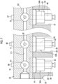
- Fig. 7 is a sectional view illustrating a modification example of the fuel-suction-side communication channel.
- the suction channels 70, 71, and 72 are disposed in the suction valves 61, 62, and 63.
- the suction valves 61, 62, and 63 are energized by the compression coil springs 76, 77, and 78 (refer to Fig. 4 ) in a direction to close the suction channels 70, 71, and 72.
- the three suction channels 70, 71, and 72 communicate with each other via a communication channel (fuel-suction-side communication channel) 111.
- the communication channel 111 is disposed at center positions of the suction channels 70, 71, and 72 (the suction valves 61, 62, and 63), and the suction channels 70, 71, and 72 can be communicated with each other.
- a fuel pump including: a pump head 23; a plurality of plunger barrel units 32A, 33A, and 34A in which a plurality of plungers 41, 42, and 43 are movably supported, which are provided with a plurality of pressurization chambers 56, 57, and 58 for pressurizing fuel by movement of the plungers 41, 42, and 43, and which are mounted in parallel on the pump head 23; a plurality of discharge valve units 64A, 65A, and 66A that are disposed in a plurality of discharge channels 73, 74, and 75 provided in the pump head 23 so as to communicate with the plurality of pressurization chambers 56, 57, and 58; a plurality of suction valve units 61A, 62A, and 63A that are disposed in a plurality of suction channels 70, 71, and 72 provided in the pump head 23 so as to communicate with the plurality of pressurization chambers 56, 57, and 58; a communication
- the plunger barrel units 32A, 33A, and 34A, the suction valve units 61A, 62A, and 63A, and the discharge valve units 64A, 65A, and 66A are independently mounted on the pump head 23. Therefore, the structures of the pump head 23, the plunger barrel units 32A, 33A, and 34A, the suction valve units 61A, 62A, and 63A, and the discharge valve units 64A, 65A, and 66A can be simplified, and thus a processing cost can be reduced.
- the discharge channels 73, 74, and 75 communicate with each other via the communication channel 85 of the pump head 23. Thereby, discharge pressure pulsation of the high-pressure fuel discharged from the discharge channels 73, 74, and 75 to the communication channel 85 is relieved by the communication channel 85. Therefore, the pressure pulsation of the fuel discharged from the connector 88 to the high-pressure fuel line L12 can be suppressed.
- the plurality of discharge channels 73, 74, and 75 are disposed in a straight line with respect to a plurality of support holes 38, 39, and 40 in which the plurality of plungers 41, 42, and 43 are movably supported, the communication channel 89 communicates with the plurality of discharge channels 73, 74, and 75 so as to intersect with the plurality of discharge channels 73, 74, and 75, and the plurality of suction channels 70, 71, and 72 communicate with the plurality of discharge channels 73, 74, and 75 so as to intersect with the plurality of discharge channels 73, 74, and 75 between the plurality of pressurization chambers 56, 57, and 58 and the communication channel 89.
- the connector 88 is provided at any one of the plurality of discharge channels 73, 74, and 75.
- the plugs of the discharge channels 73, 74, and 75 can also be used as the connector 88, and thus the structure can be simplified.
- the plunger barrel units 32A, 33A, and 34A are provided with first shaft portions (convex portions) 32a, 33a, and 34a on one end portion side in an axial direction
- the pump head 23 is provided with the accommodation holes (recess portions) 35, 36, and 37
- the first shaft portions 32a, 33a, and 34a are fitted into the accommodation holes 35, 36, and 37 for positioning.
- the plunger barrel units 32A, 33A, and 34A can be mounted on the pump head 23 with high accuracy.
- a pair of communication channels (fuel-suction-side communication channels) 85 communicating with the plurality of suction channels 70, 71, and 72 are provided on both sides of the suction channels 70, 71, and 72 in the radial direction.
- the fuel is supplied from the pair of communication channels 85 to the suction channels 70, 71, and 72. Therefore, even in a case where air is mixed with the fuel, the mixed air is quickly discharged to the pressurization chambers 56, 57, and 58, and thus it possible to suppress fluctuations in the fuel discharge amount.
- the support holes 38, 39, and 40 have the same diameter in the axial direction, and one end portions of the support holes 38, 39, and 40 communicate with the fuel channels 67, 68, and 69.
- the present invention is not limited to the configuration.
- the support hole may be configured with a main body hole having the same diameter as the support holes 38, 39, and 40 and a small diameter portion having a diameter smaller than the diameter of the support holes 38, 39, and 40, and the small diameter portion may communicate with the fuel channels 67, 68, and 69.
- the plungers 41, 42, and 43 are movably supported only by the main body holes.
- a form of the fuel injection device 10 and a form of the fuel pump 11 are not limited to the above-described embodiment.
- the number of the common rails 12 and the fuel injectors 13, the connection position of the fuel pump 11, the number of the plungers 41, 42, and 43, and the plunger barrels 32, 33, and 34 may be appropriately set.
Landscapes
- Engineering & Computer Science (AREA)
- Mechanical Engineering (AREA)
- General Engineering & Computer Science (AREA)
- Chemical & Material Sciences (AREA)
- Combustion & Propulsion (AREA)
- Fuel-Injection Apparatus (AREA)
Abstract
Description
- The present disclosure relates to a fuel pump applied to an internal combustion engine.
- For example, a common-rail-type fuel injection device applied to a diesel engine includes a fuel pump, a common rail, and a fuel injector. The fuel pump inhales fuel from a fuel tank, pressurizes the fuel, and supplies the fuel to the common rail as high-pressure fuel. The common rail holds the high-pressure fuel supplied from the fuel pump at a predetermined pressure. The fuel injector injects the high-pressure fuel of the common rail into a combustion chamber of the diesel engine by opening and closing the injector. The fuel pump includes plunger barrels, plungers, suction valves, and discharge valves. In a case where the plunger moves inside the plunger barrel in one direction, the suction valve is opened and the fuel is inhaled into the pressurization chamber. In a case where the plunger moves inside the plunger barrel in the other direction, the fuel in the pressurization chamber is pressurized, and the discharge valve is opened to discharge the high-pressure fuel. Examples of such a fuel pump include a fuel pump described in
PTL 1 below. - [PTL 1]
Japanese Patent No. 5182125 - In the fuel pump, plungers and plunger barrels are respectively disposed corresponding to a plurality of cams provided on a cam shaft. That is, the fuel pump is configured by disposing plunger units in which a plunger, a suction valve, and a discharge valve are mounted on a plunger barrel at an interval in an axial direction of a cam shaft and connecting the plunger units to each other. For this reason, one plunger unit becomes large, and the plunger barrel has a complicated shape. As a result, there is a problem that processing is difficult and a processing cost increases.
- In addition, in each of a plurality of plunger units, each fuel discharge unit is connected to the common rail via each connection pipe. For this reason, a connection structure between the plunger unit and the common rail becomes complicated, and pressure pulsation occurs at different timings in each connection pipe. As a result, this will adversely affect a fuel discharge amount, a fuel discharge pressure, and the like.
- The present disclosure has been made to solve the above-described problem, and an object of the present disclosure is to provide a fuel pump that suppresses occurrence of fuel pressure pulsation while simplifying a structure and reducing a processing cost.
- In order to achieve the above object, there is provided a fuel pump including: a pump head; a plurality of plunger barrel units in which a plurality of plungers are movably supported, which are provided with a plurality of pressurization chambers for pressurizing fuel by movement of the plungers, and which are mounted in parallel on the pump head; a plurality of discharge valve units that are disposed in a plurality of fuel discharge channels provided in the pump head so as to communicate with the plurality of pressurization chambers; a plurality of suction valve units that are disposed in a plurality of fuel suction channels provided in the pump head so as to communicate with the plurality of pressurization chambers; a fuel-discharge-side communication channel that communicates with the plurality of fuel discharge channels; and a connector that supplies the fuel of the fuel-discharge-side communication channel to outside.
- According to the fuel pump of the present disclosure, it is possible to simplify a structure and reduce a processing cost, and it is possible to suppress occurrence of fuel pressure pulsation.
-
-
Fig. 1 is a schematic configuration diagram illustrating a fuel injection device of the present embodiment. -
Fig. 2 is a vertical sectional view illustrating a fuel pump of the present embodiment. -
Fig. 3 is a sectional view taken along a III-III line ofFig. 2 illustrating a vertical section of the fuel pump. -
Fig. 4 is a sectional view illustrating a connection relationship between a pump head, a plunger barrel unit, a suction valve unit, and a discharge valve unit. -
Fig. 5 is a sectional view taken along a V-V line ofFig. 4 . -
Fig. 6 is a sectional view taken along a VI-VI line ofFig. 4 . -
Fig. 7 is a sectional view illustrating a modification example of a fuel-suction-side communication channel. Description of Embodiments - Hereinafter, a preferred embodiment of the present disclosure will be described in detail with reference to the drawings. The present disclosure is not limited by the embodiment, and in a case where there are a plurality of embodiments, the present disclosure also includes a configuration in which the respective embodiments are combined with each other. In addition, components in the embodiment include components that can be easily assumed by those skilled in the art, components that are substantially the same, or components that fall within an equivalent range.
-
Fig. 1 is a schematic configuration diagram illustrating a fuel injection device of the present embodiment. - As illustrated in
Fig. 1 , thefuel injection device 10 is mounted on a diesel engine (internal combustion engine). Thefuel injection device 10 includes afuel pump 11, a common rail 12, and a plurality offuel injectors 13. - A
fuel tank 14 is connected to thefuel pump 11 via a fuel line L11. Thefuel pump 11 inhales the fuel stored in thefuel tank 14 from the fuel line L11, and pressurizes the fuel to generate high-pressure fuel. The common rail 12 is connected to thefuel pump 11 via a high-pressure fuel line L12. The common rail 12 adjusts the high-pressure fuel supplied from thefuel pump 11 to a predetermined pressure. Thefuel injectors 13 are respectively connected to the common rail 12 via a plurality of (in the present embodiment, four) fuel supply lines L13. Thefuel injector 13 injects the high-pressure fuel of the common rail 12 into each cylinder (combustion chamber) of the diesel engine by opening and closing the injector. -
Fig. 2 is a vertical sectional view illustrating the fuel pump of the present embodiment, andFig. 3 is a sectional view taken along a III-III line ofFig. 2 illustrating a vertical section of the fuel pump. The fuel pump to be described below has a type in which three plungers are disposed. On the other hand, the number of the plungers is not limited thereto. - As illustrated in
Fig. 2 andFig. 3 , a housing of thefuel pump 11 is configured by bolt-fastening aretainer 21, apump casing 22, and apump head 23. Acam shaft 24 is disposed inside thepump casing 22. Each end portion of thecam shaft 24 in an axial direction is rotatably supported by theretainer 21 bybearings cam shaft 24 in the axial direction protrudes to the outside of theretainer 21, and a driving force is input from the diesel engine. In thecam shaft 24, a plurality of (in the present embodiment, three)cams cams - The
retainer 21 is fastened to thepump casing 22 by a plurality ofbolts 30. The plurality ofbolts 30 penetrate theretainer 21, and tip portions of the plurality ofbolts 30 are screwed to thepump casing 22. Thepump head 23 is fastened to thepump casing 22 by a plurality ofbolts 31. The plurality ofbolts 31 penetrate thepump head 23, and are screwed into thepump casing 22. - Three
plunger barrels pump casing 22 and thepump head 23. Each of theplunger barrels pump casing 22 and thepump head 23 are provided with threeaccommodation holes cam shaft 24. The accommodation holes 35, 36, and 37 are formed across thepump casing 22 and thepump head 23. Each of the plunger barrels 32, 33, and 34 is disposed in each of the accommodation holes 35, 36, and 37. That is, the plunger barrels 32, 33, and 34 respectively includesfirst shaft portions second shaft portions third shaft portions first shaft portions second shaft portions third shaft portions first shaft portions - Support holes 38, 39, and 40 are respectively formed inside the plunger barrels 32, 33, and 34 along the axial direction. The support holes 38, 39, and 40 respectively penetrate the plunger barrels 32, 33, and 34 in the axial direction. In the plunger barrels 32, 33, and 34,
plungers plungers -
Tappets rollers plungers cams rollers tappets plungers spring seats spring seats plungers tappets spring seats rollers cams tappets rollers cams - In the plunger barrels 32, 33, and 34,
pressurization chambers pressurization chambers plungers discharge valves suction valves plungers pressurization chambers - In the
pump head 23,suction valves discharge valves pump head 23,fuel channels fuel channels fuel channels fuel channels fuel channels suction channels fuel channels fuel channels - In the
suction channels suction valves suction valves suction channels suction channels discharge valves discharge channels discharge valves discharge channels discharge channels pressurization chambers fuel channels suction channels - The three
suction channels Fig. 1 ) is connected to thecommunication channel 85.Plugs discharge channels discharge channels connector 88 is mounted to the other end portion of thedischarge channel 74. In addition, the threedischarge channels Fig. 1 ) is connected to theconnector 88 via the high-pressure fuel line L12. Thecommunication channel 89 allows thedischarge channels communication channel 89 may be disposed in a linear shape to intersect with thedischarge channels discharge channels communication channel 89 may be disposed with an offset in a direction perpendicular to the paper surface ofFig. 2 , and may indirectly communicate with thedischarge channels - Therefore, when the
cam shaft 24 rotates, a rotational force is converted into a reciprocating force by thecams rollers tappets rollers tappets plungers suction valves suction channels plungers Fig. 2 andFig. 3 ), the low-pressure fuel in thecommunication channel 85 is inhaled into thepressurization chambers suction channels fuel channels plungers plungers suction valves suction channels - In a state where the low-pressure fuel is inhaled into the
pressurization chambers plungers Fig. 2 andFig. 3 ), before the actuators 79, 80, and 81 are operated, the low-pressure fuel is returned from thesuction channels communication channel 85 via thesuction valves suction valves pressurization chambers pressurization chambers pressurization chambers discharge valves discharge channels pressurization chambers fuel channels discharge channels discharge channels communication channel 89, and is discharged from theconnector 88 to the high-pressure fuel line L12 (refer toFig. 1 ). Thereafter, when theplungers plungers pressurization chambers pressurization chambers discharge valves discharge channels -
Fig. 4 is a sectional view illustrating a connection relationship between a pump head, a plunger barrel unit, a suction valve unit, and a discharge valve unit,Fig. 5 is a sectional view taken along a V-V line ofFig. 4 , andFig. 6 is a sectional view taken along a VI-VI line ofFig. 4 . - As illustrated in
Fig. 4 to Fig. 6 , thepump head 23 is fastened to thepump casing 22 bybolts 31. Thepump casing 22 and thepump head 23 are provided withaccommodation holes pump head 23. A plurality ofbolts 91 penetrate thepump head 23, and tip portions of thebolts 91 are screwed to thefirst shaft portions - Support holes 38, 39, and 40 are formed in the plunger barrels 32, 33, and 34, and the
plungers pump head 23 is provided withfuel channels fuel channels suction channels suction channels discharge channels suction valves suction channels discharge valves fuel channels discharge channels - In the present embodiment, the plunger barrels 32, 33, and 34, the
suction valves discharge valves pump head 23. Theplunger barrel units pump head 23. Thesuction valve units suction channels discharge valve units fuel channels discharge channels - As illustrated in
Fig. 4 , theplunger barrel units plungers plunger barrel units tappets rollers - Next, the
suction valve units suction valve units suction valve unit 62A will be described. - As illustrated in
Fig. 4 , thepump head 23 is provided with thefuel channel 68, thesuction channel 71, and thedischarge channel 74. Thesupport hole 39, thefuel channel 68, and thedischarge channel 74 are disposed in a straight line, and communicate with each other. Thesuction channel 71 is disposed to be orthogonal to thefuel channel 68, and one end portion of thesuction channel 71 communicates with thefuel channel 68. In thepump head 23, anaccommodation recess portion 101 is formed to communicate with the other end portion of thesuction channel 71. Asuction valve casing 102 and a fixingmember 103 are disposed in theaccommodation recess portion 101. Thesuction valve 62 is movably supported in the axial direction inside thesuction valve casing 102, and thesuction valve casing 102 is disposed on thesuction channel 71 side in theaccommodation recess 101. The fixingmember 103 is disposed in contact with thesuction valve casing 102 on the opening side of theaccommodation recess portion 101, and is fixed to thepump head 23. Thus, thesuction valve casing 102 is positioned and is fixed to thepump head 23. - The compression coil spring 77 is disposed between the
suction valve 62 and thesuction valve casing 102. Thesuction valve 62 is supported by the energizing force of the compression coil spring 77 in a direction to open thesuction channel 71. In addition, thesuction valve 62 is movable so as to close thesuction channel 71 by the actuator 80. Further, in thepump head 23,communication channels 104 and 105 are formed on both sides of thesuction valve 62 in a radial direction along a direction intersecting with thesuction channel 71. Thecommunication channels 104 and 105 communicate with thesuction channel 71 viaopenings suction valve casing 102. The twocommunication channels 85 are configured with thecommunication channels 104 and 105 and theopenings communication channels 85 are disposed to be shifted with respect to center positions of thesuction channels suction valves suction channels - The
suction valve units suction valve casing 102, the fixingmember 103, and the like, in addition to thesuction valves suction valve units - In addition, as illustrated in
Fig. 5 , thefuel channels discharge channels discharge valves fuel channels discharge channels discharge valves plugs compression coil spring 83 is disposed between thedischarge valve 65 and theconnector 88. Thedischarge valves discharge channels pressurization chambers discharge channels - The three
discharge channels communication channel 89. In this case, thecommunication channel 89 has a linear shape along a direction orthogonal to thefuel channels discharge channels communication channel 89 allows thedischarge channel 73, thedischarge channel 74, and thedischarge channel 75 to communicate with each other. In addition, theconnector 88 is provided at an end portion of thedischarge channel 74. Theconnector 88 may be provided not at thedischarge channel 74 but at thedischarge channel 73 or thedischarge channel 75, or may be provided so as to communicate with thecommunication channel 89. - The
discharge valve units discharge valves discharge valve units - In the
fuel pump 11, the plurality ofplunger barrel units suction valve units discharge valve units pump head 23. Therefore, structures of thepump head 23, theplunger barrel units suction valve units discharge valve units discharge channels communication channel 85 of thepump head 23. Thereby, discharge pressure pulsation of the high-pressure fuel discharged from thedischarge channels communication channel 85 is relieved by thecommunication channel 85. Therefore, the pressure pulsation of the fuel discharged from theconnector 88 to the high-pressure fuel line L12 is suppressed. -
Fig. 7 is a sectional view illustrating a modification example of the fuel-suction-side communication channel. - In a modification example of the present embodiment, as illustrated in
Fig. 7 , thesuction channels suction valves suction valves Fig. 4 ) in a direction to close thesuction channels suction channels communication channel 111 is disposed at center positions of thesuction channels suction valves suction channels - According to a first aspect, there is provided a fuel pump including: a
pump head 23; a plurality ofplunger barrel units plungers pressurization chambers plungers pump head 23; a plurality ofdischarge valve units discharge channels pump head 23 so as to communicate with the plurality ofpressurization chambers suction valve units suction channels pump head 23 so as to communicate with the plurality ofpressurization chambers discharge channels connector 88 that supplies the fuel of thecommunication channel 89 to outside. - With the fuel pump according to the first aspect, the
plunger barrel units suction valve units discharge valve units pump head 23. Therefore, the structures of thepump head 23, theplunger barrel units suction valve units discharge valve units plunger barrel units pump head 23, it is possible to easily change the design according to the number of theplunger barrel units discharge channels communication channel 85 of thepump head 23. Thereby, discharge pressure pulsation of the high-pressure fuel discharged from thedischarge channels communication channel 85 is relieved by thecommunication channel 85. Therefore, the pressure pulsation of the fuel discharged from theconnector 88 to the high-pressure fuel line L12 can be suppressed. - In the fuel pump according to a second aspect, the plurality of
discharge channels plungers communication channel 89 communicates with the plurality ofdischarge channels discharge channels suction channels discharge channels discharge channels pressurization chambers communication channel 89. Thereby, only thefuel channels pressurization chambers pressurization chambers - In the fuel pump according to a third aspect, the
connector 88 is provided at any one of the plurality ofdischarge channels discharge channels connector 88, and thus the structure can be simplified. - In the fuel pump according to a fourth aspect,
theplunger barrel units pump head 23 is provided with the accommodation holes (recess portions) 35, 36, and 37, and thefirst shaft portions plunger barrel units pump head 23 with high accuracy. - In the fuel pump according to a fifth aspect, a pair of communication channels (fuel-suction-side communication channels) 85 communicating with the plurality of
suction channels suction channels communication channels 85 to thesuction channels pressurization chambers - In the above-described embodiment, the support holes 38, 39, and 40 have the same diameter in the axial direction, and one end portions of the support holes 38, 39, and 40 communicate with the
fuel channels fuel channels plungers - Further, a form of the
fuel injection device 10 and a form of thefuel pump 11 are not limited to the above-described embodiment. For example, the number of the common rails 12 and thefuel injectors 13, the connection position of thefuel pump 11, the number of theplungers -
- 10: fuel injection device
- 11: fuel pump
- 12: common rail
- 13: fuel injector
- 14: fuel tank
- 21: retainer
- 22: pump casing
- 23: pump head
- 24: cam shaft
- 25, 26: bearing
- 27, 28, 29: cam
- 30, 31: bolt
- 32, 33, 34: plunger barrel
- 35, 36, 37: accommodation hole (recess portion)
- 38, 39, 40: support hole
- 41, 42, 43: plunger
- 44, 45, 46: tappet
- 47, 48, 49: roller
- 50, 51, 52: supporting shaft
- 53, 54, 55: compression coil spring
- 61, 62, 63: suction valve
- 64, 65, 66: discharge valve
- 67, 68, 69: fuel channel
- 70, 71, 72: suction channel
- 73, 74, 75: discharge channel
- 76, 77, 78: compression coil spring
- 79, 80, 81: actuator
- 82, 83, 84: compression coil spring
- 85: communication channel (fuel-suction-side communication channel)
- 86, 87: plug
- 88: connector
- 89: communication channel (fuel-discharge-side communication channel)
- 91: bolt
- 101: accommodation recess portion
- 102: suction valve casing
- 103: fixing member
- 104, 105: communication channel
- 106, 107: opening
- l11: fuel line
- l12: high-pressure fuel line
- l13: fuel supply line
Claims (5)
- A fuel pump comprising:a pump head;a plurality of plunger barrel units in which a plurality of plungers are movably supported, which are provided with a plurality of pressurization chambers for pressurizing fuel by movement of the plungers, and which are mounted in parallel on the pump head;a plurality of discharge valve units that are disposed in a plurality of fuel discharge channels provided in the pump head so as to communicate with the plurality of pressurization chambers;a plurality of suction valve units that are disposed in a plurality of fuel suction channels provided in the pump head so as to communicate with the plurality of pressurization chambers;a fuel-discharge-side communication channel that communicates with the plurality of fuel discharge channels; anda connector that supplies the fuel of the fuel-discharge-side communication channel to outside.
- The fuel pump according to claim 1, whereinthe plurality of fuel discharge channels are disposed in a straight line with respect to a plurality of support holes in which the plurality of plungers are movably supported,the fuel-discharge-side communication channel communicates with the plurality of fuel discharge channels so as to intersect with the plurality of fuel discharge channels, andthe plurality of fuel suction channels communicate with the plurality of fuel discharge channels so as to intersect with the plurality of fuel discharge channels between the plurality of pressurization chambers and the fuel-discharge-side communication channel.
- The fuel pump according to Claim 1 or 2,
wherein the connector is provided at any one of the plurality of fuel discharge channels. - The fuel pump according to any one of Claims 1 to 3, whereinthe plunger barrel unit is provided with a convex portion on one end portion side in an axial direction,the pump head is provided with a recess portion, andthe convex portion is fitted into the recess portion for positioning.
- The fuel pump according to any one of Claims 1 to 4,
wherein fuel-suction-side communication channels communicating with the plurality of fuel suction channels are provided on both sides of the fuel suction channel in a radial direction.
Applications Claiming Priority (2)
| Application Number | Priority Date | Filing Date | Title |
|---|---|---|---|
| JP2021112245A JP2023008574A (en) | 2021-07-06 | 2021-07-06 | Fuel pump |
| PCT/JP2022/023810 WO2023281992A1 (en) | 2021-07-06 | 2022-06-14 | Fuel pump |
Publications (2)
| Publication Number | Publication Date |
|---|---|
| EP4332366A1 true EP4332366A1 (en) | 2024-03-06 |
| EP4332366A4 EP4332366A4 (en) | 2024-10-30 |
Family
ID=84800579
Family Applications (1)
| Application Number | Title | Priority Date | Filing Date |
|---|---|---|---|
| EP22837410.4A Pending EP4332366A4 (en) | 2021-07-06 | 2022-06-14 | Fuel pump |
Country Status (6)
| Country | Link |
|---|---|
| US (2) | US20240295203A1 (en) |
| EP (1) | EP4332366A4 (en) |
| JP (1) | JP2023008574A (en) |
| KR (1) | KR20230169383A (en) |
| CN (1) | CN117460883A (en) |
| WO (1) | WO2023281992A1 (en) |
Families Citing this family (2)
| Publication number | Priority date | Publication date | Assignee | Title |
|---|---|---|---|---|
| JP7783702B2 (en) * | 2021-07-06 | 2025-12-10 | 三菱重工エンジン&ターボチャージャ株式会社 | fuel pump |
| US12510047B1 (en) * | 2024-06-27 | 2025-12-30 | Transportation Ip Holdings, Llc | Inlet metering valve block |
Family Cites Families (7)
| Publication number | Priority date | Publication date | Assignee | Title |
|---|---|---|---|---|
| JPH07269461A (en) * | 1994-03-29 | 1995-10-17 | Yamaha Motor Co Ltd | Fuel supply device |
| FI945679A0 (en) * | 1994-12-01 | 1994-12-01 | Waertsilae Nsd Oy Ab | Foerbaettrat foerfarande Foer insprutning av ett tryckmedium i cylindern vid en foerbraenningsmotor samt arrangemang Foer tillaempning av foerfarandet |
| US7431019B2 (en) * | 2004-03-05 | 2008-10-07 | Bosch Corporation | Fuel supply device |
| JP5182125B2 (en) | 2009-01-29 | 2013-04-10 | 株式会社デンソー | Fuel supply pump |
| JP2013053555A (en) * | 2011-09-05 | 2013-03-21 | Bosch Corp | Fuel supply pump |
| CN110685841B (en) * | 2019-11-08 | 2024-10-22 | 重庆红江机械有限责任公司 | Multi-cylinder combined high-pressure oil pump of marine low-speed machine |
| CN112780470A (en) * | 2020-12-10 | 2021-05-11 | 重庆红江机械有限责任公司 | Common rail type high-pressure fuel injection pump for marine high-speed diesel engine |
-
2021
- 2021-07-06 JP JP2021112245A patent/JP2023008574A/en active Pending
-
2022
- 2022-06-14 KR KR1020237040395A patent/KR20230169383A/en not_active Ceased
- 2022-06-14 CN CN202280038542.0A patent/CN117460883A/en active Pending
- 2022-06-14 WO PCT/JP2022/023810 patent/WO2023281992A1/en not_active Ceased
- 2022-06-14 EP EP22837410.4A patent/EP4332366A4/en active Pending
- 2022-06-14 US US18/565,378 patent/US20240295203A1/en active Pending
-
2025
- 2025-06-03 US US19/227,077 patent/US20250290479A1/en active Pending
Also Published As
| Publication number | Publication date |
|---|---|
| JP2023008574A (en) | 2023-01-19 |
| WO2023281992A1 (en) | 2023-01-12 |
| US20250290479A1 (en) | 2025-09-18 |
| CN117460883A (en) | 2024-01-26 |
| EP4332366A4 (en) | 2024-10-30 |
| US20240295203A1 (en) | 2024-09-05 |
| KR20230169383A (en) | 2023-12-15 |
Similar Documents
| Publication | Publication Date | Title |
|---|---|---|
| US20250290479A1 (en) | Fuel pump | |
| US6457957B1 (en) | Radial piston pump for generating high fuel pressure | |
| JP4243630B2 (en) | High pressure pump especially for fuel injection devices of internal combustion engines | |
| JP2010229924A (en) | High pressure pump | |
| EP4332367A1 (en) | Fuel pump | |
| JP2010229914A (en) | High pressure pump | |
| US20120080013A1 (en) | High pressure pump and tappet assembly | |
| US20130206110A1 (en) | Pump And Common Rail Fuel Injection System | |
| EP1277950A1 (en) | High-pressure pump | |
| US12372051B2 (en) | Fuel pump | |
| US20180328329A1 (en) | Relief valve device and high-pressure pump using same | |
| US11280306B1 (en) | Fuel injector having dry-running protection valve and fuel system using same | |
| KR102722649B1 (en) | High pressure pump with fluid damper | |
| JP2015137578A (en) | High pressure pump | |
| JP4045382B2 (en) | Fuel supply device | |
| EP4741659A2 (en) | Compact opposed pump | |
| JP2017031918A (en) | Fuel injection pump, fuel injection device, internal combustion engine | |
| US12631164B2 (en) | Compact opposed pump | |
| JP2001304071A (en) | High pressure supply pump | |
| US11220980B2 (en) | Fuel system having isolation valves between fuel injectors and common drain conduit | |
| JP4367395B2 (en) | Fuel supply device | |
| JP2001165015A (en) | Fuel injection pump | |
| JPH0710464U (en) | Unit injector | |
| KR20000014121A (en) | Compressed type fuel ejection device |
Legal Events
| Date | Code | Title | Description |
|---|---|---|---|
| STAA | Information on the status of an ep patent application or granted ep patent |
Free format text: STATUS: THE INTERNATIONAL PUBLICATION HAS BEEN MADE |
|
| PUAI | Public reference made under article 153(3) epc to a published international application that has entered the european phase |
Free format text: ORIGINAL CODE: 0009012 |
|
| STAA | Information on the status of an ep patent application or granted ep patent |
Free format text: STATUS: REQUEST FOR EXAMINATION WAS MADE |
|
| 17P | Request for examination filed |
Effective date: 20231129 |
|
| AK | Designated contracting states |
Kind code of ref document: A1 Designated state(s): AL AT BE BG CH CY CZ DE DK EE ES FI FR GB GR HR HU IE IS IT LI LT LU LV MC MK MT NL NO PL PT RO RS SE SI SK SM TR |
|
| DAV | Request for validation of the european patent (deleted) | ||
| DAX | Request for extension of the european patent (deleted) | ||
| A4 | Supplementary search report drawn up and despatched |
Effective date: 20241002 |
|
| RIC1 | Information provided on ipc code assigned before grant |
Ipc: F04B 53/16 20060101ALI20240926BHEP Ipc: F04B 1/0452 20200101ALI20240926BHEP Ipc: F04B 1/0421 20200101ALI20240926BHEP Ipc: F02M 59/46 20060101ALI20240926BHEP Ipc: F02M 59/10 20060101ALI20240926BHEP Ipc: F02M 37/00 20060101ALI20240926BHEP Ipc: F02M 59/44 20060101ALI20240926BHEP Ipc: F02M 59/08 20060101ALI20240926BHEP Ipc: F02M 59/04 20060101ALI20240926BHEP Ipc: F02M 55/02 20060101AFI20240926BHEP |