EP4332271A1 - Efficient oxyhydrogen generation device for medical care, and method therefor - Google Patents
Efficient oxyhydrogen generation device for medical care, and method therefor Download PDFInfo
- Publication number
- EP4332271A1 EP4332271A1 EP21963805.3A EP21963805A EP4332271A1 EP 4332271 A1 EP4332271 A1 EP 4332271A1 EP 21963805 A EP21963805 A EP 21963805A EP 4332271 A1 EP4332271 A1 EP 4332271A1
- Authority
- EP
- European Patent Office
- Prior art keywords
- gas
- water supply
- tank
- water
- supply tank
- Prior art date
- Legal status (The legal status is an assumption and is not a legal conclusion. Google has not performed a legal analysis and makes no representation as to the accuracy of the status listed.)
- Pending
Links
Images


Classifications
-
- C—CHEMISTRY; METALLURGY
- C25—ELECTROLYTIC OR ELECTROPHORETIC PROCESSES; APPARATUS THEREFOR
- C25B—ELECTROLYTIC OR ELECTROPHORETIC PROCESSES FOR THE PRODUCTION OF COMPOUNDS OR NON-METALS; APPARATUS THEREFOR
- C25B1/00—Electrolytic production of inorganic compounds or non-metals
- C25B1/01—Products
- C25B1/02—Hydrogen or oxygen
- C25B1/04—Hydrogen or oxygen by electrolysis of water
-
- C—CHEMISTRY; METALLURGY
- C25—ELECTROLYTIC OR ELECTROPHORETIC PROCESSES; APPARATUS THEREFOR
- C25B—ELECTROLYTIC OR ELECTROPHORETIC PROCESSES FOR THE PRODUCTION OF COMPOUNDS OR NON-METALS; APPARATUS THEREFOR
- C25B1/00—Electrolytic production of inorganic compounds or non-metals
- C25B1/01—Products
- C25B1/02—Hydrogen or oxygen
- C25B1/04—Hydrogen or oxygen by electrolysis of water
- C25B1/044—Hydrogen or oxygen by electrolysis of water producing mixed hydrogen and oxygen gas, e.g. Brown's gas [HHO]
-
- C—CHEMISTRY; METALLURGY
- C01—INORGANIC CHEMISTRY
- C01B—NON-METALLIC ELEMENTS; COMPOUNDS THEREOF; METALLOIDS OR COMPOUNDS THEREOF NOT COVERED BY SUBCLASS C01C
- C01B13/00—Oxygen; Ozone; Oxides or hydroxides in general
- C01B13/02—Preparation of oxygen
- C01B13/0203—Preparation of oxygen from inorganic compounds
- C01B13/0207—Water
-
- C—CHEMISTRY; METALLURGY
- C25—ELECTROLYTIC OR ELECTROPHORETIC PROCESSES; APPARATUS THEREFOR
- C25B—ELECTROLYTIC OR ELECTROPHORETIC PROCESSES FOR THE PRODUCTION OF COMPOUNDS OR NON-METALS; APPARATUS THEREFOR
- C25B15/00—Operating or servicing cells
-
- C—CHEMISTRY; METALLURGY
- C25—ELECTROLYTIC OR ELECTROPHORETIC PROCESSES; APPARATUS THEREFOR
- C25B—ELECTROLYTIC OR ELECTROPHORETIC PROCESSES FOR THE PRODUCTION OF COMPOUNDS OR NON-METALS; APPARATUS THEREFOR
- C25B15/00—Operating or servicing cells
- C25B15/02—Process control or regulation
- C25B15/023—Measuring, analysing or testing during electrolytic production
-
- C—CHEMISTRY; METALLURGY
- C25—ELECTROLYTIC OR ELECTROPHORETIC PROCESSES; APPARATUS THEREFOR
- C25B—ELECTROLYTIC OR ELECTROPHORETIC PROCESSES FOR THE PRODUCTION OF COMPOUNDS OR NON-METALS; APPARATUS THEREFOR
- C25B15/00—Operating or servicing cells
- C25B15/08—Supplying or removing reactants or electrolytes; Regeneration of electrolytes
-
- C—CHEMISTRY; METALLURGY
- C25—ELECTROLYTIC OR ELECTROPHORETIC PROCESSES; APPARATUS THEREFOR
- C25B—ELECTROLYTIC OR ELECTROPHORETIC PROCESSES FOR THE PRODUCTION OF COMPOUNDS OR NON-METALS; APPARATUS THEREFOR
- C25B9/00—Cells or assemblies of cells; Constructional parts of cells; Assemblies of constructional parts, e.g. electrode-diaphragm assemblies; Process-related cell features
- C25B9/17—Cells comprising dimensionally-stable non-movable electrodes; Assemblies of constructional parts thereof
-
- C—CHEMISTRY; METALLURGY
- C25—ELECTROLYTIC OR ELECTROPHORETIC PROCESSES; APPARATUS THEREFOR
- C25B—ELECTROLYTIC OR ELECTROPHORETIC PROCESSES FOR THE PRODUCTION OF COMPOUNDS OR NON-METALS; APPARATUS THEREFOR
- C25B9/00—Cells or assemblies of cells; Constructional parts of cells; Assemblies of constructional parts, e.g. electrode-diaphragm assemblies; Process-related cell features
- C25B9/60—Constructional parts of cells
- C25B9/67—Heating or cooling means
-
- C—CHEMISTRY; METALLURGY
- C25—ELECTROLYTIC OR ELECTROPHORETIC PROCESSES; APPARATUS THEREFOR
- C25B—ELECTROLYTIC OR ELECTROPHORETIC PROCESSES FOR THE PRODUCTION OF COMPOUNDS OR NON-METALS; APPARATUS THEREFOR
- C25B9/00—Cells or assemblies of cells; Constructional parts of cells; Assemblies of constructional parts, e.g. electrode-diaphragm assemblies; Process-related cell features
- C25B9/70—Assemblies comprising two or more cells
-
- C—CHEMISTRY; METALLURGY
- C25—ELECTROLYTIC OR ELECTROPHORETIC PROCESSES; APPARATUS THEREFOR
- C25B—ELECTROLYTIC OR ELECTROPHORETIC PROCESSES FOR THE PRODUCTION OF COMPOUNDS OR NON-METALS; APPARATUS THEREFOR
- C25B9/00—Cells or assemblies of cells; Constructional parts of cells; Assemblies of constructional parts, e.g. electrode-diaphragm assemblies; Process-related cell features
- C25B9/70—Assemblies comprising two or more cells
- C25B9/73—Assemblies comprising two or more cells of the filter-press type
-
- C—CHEMISTRY; METALLURGY
- C25—ELECTROLYTIC OR ELECTROPHORETIC PROCESSES; APPARATUS THEREFOR
- C25B—ELECTROLYTIC OR ELECTROPHORETIC PROCESSES FOR THE PRODUCTION OF COMPOUNDS OR NON-METALS; APPARATUS THEREFOR
- C25B9/00—Cells or assemblies of cells; Constructional parts of cells; Assemblies of constructional parts, e.g. electrode-diaphragm assemblies; Process-related cell features
- C25B9/70—Assemblies comprising two or more cells
- C25B9/73—Assemblies comprising two or more cells of the filter-press type
- C25B9/75—Assemblies comprising two or more cells of the filter-press type having bipolar electrodes
-
- A—HUMAN NECESSITIES
- A61—MEDICAL OR VETERINARY SCIENCE; HYGIENE
- A61M—DEVICES FOR INTRODUCING MEDIA INTO, OR ONTO, THE BODY; DEVICES FOR TRANSDUCING BODY MEDIA OR FOR TAKING MEDIA FROM THE BODY; DEVICES FOR PRODUCING OR ENDING SLEEP OR STUPOR
- A61M16/00—Devices for influencing the respiratory system of patients by gas treatment, e.g. ventilators; Tracheal tubes
- A61M16/10—Preparation of respiratory gases or vapours
-
- A—HUMAN NECESSITIES
- A61—MEDICAL OR VETERINARY SCIENCE; HYGIENE
- A61M—DEVICES FOR INTRODUCING MEDIA INTO, OR ONTO, THE BODY; DEVICES FOR TRANSDUCING BODY MEDIA OR FOR TAKING MEDIA FROM THE BODY; DEVICES FOR PRODUCING OR ENDING SLEEP OR STUPOR
- A61M16/00—Devices for influencing the respiratory system of patients by gas treatment, e.g. ventilators; Tracheal tubes
- A61M16/0003—Accessories therefor, e.g. sensors, vibrators, negative pressure
- A61M2016/0027—Accessories therefor, e.g. sensors, vibrators, negative pressure pressure meter
-
- A—HUMAN NECESSITIES
- A61—MEDICAL OR VETERINARY SCIENCE; HYGIENE
- A61M—DEVICES FOR INTRODUCING MEDIA INTO, OR ONTO, THE BODY; DEVICES FOR TRANSDUCING BODY MEDIA OR FOR TAKING MEDIA FROM THE BODY; DEVICES FOR PRODUCING OR ENDING SLEEP OR STUPOR
- A61M2202/00—Special media to be introduced, removed or treated
- A61M2202/02—Gases
- A61M2202/0208—Oxygen
-
- A—HUMAN NECESSITIES
- A61—MEDICAL OR VETERINARY SCIENCE; HYGIENE
- A61M—DEVICES FOR INTRODUCING MEDIA INTO, OR ONTO, THE BODY; DEVICES FOR TRANSDUCING BODY MEDIA OR FOR TAKING MEDIA FROM THE BODY; DEVICES FOR PRODUCING OR ENDING SLEEP OR STUPOR
- A61M2205/00—General characteristics of the apparatus
- A61M2205/33—Controlling, regulating or measuring
- A61M2205/3379—Masses, volumes, levels of fluids in reservoirs, flow rates
- A61M2205/3389—Continuous level detection
-
- A—HUMAN NECESSITIES
- A61—MEDICAL OR VETERINARY SCIENCE; HYGIENE
- A61M—DEVICES FOR INTRODUCING MEDIA INTO, OR ONTO, THE BODY; DEVICES FOR TRANSDUCING BODY MEDIA OR FOR TAKING MEDIA FROM THE BODY; DEVICES FOR PRODUCING OR ENDING SLEEP OR STUPOR
- A61M2205/00—General characteristics of the apparatus
- A61M2205/36—General characteristics of the apparatus related to heating or cooling
- A61M2205/3606—General characteristics of the apparatus related to heating or cooling cooled
-
- A—HUMAN NECESSITIES
- A61—MEDICAL OR VETERINARY SCIENCE; HYGIENE
- A61M—DEVICES FOR INTRODUCING MEDIA INTO, OR ONTO, THE BODY; DEVICES FOR TRANSDUCING BODY MEDIA OR FOR TAKING MEDIA FROM THE BODY; DEVICES FOR PRODUCING OR ENDING SLEEP OR STUPOR
- A61M2205/00—General characteristics of the apparatus
- A61M2205/36—General characteristics of the apparatus related to heating or cooling
- A61M2205/362—General characteristics of the apparatus related to heating or cooling by gas flow
-
- A—HUMAN NECESSITIES
- A61—MEDICAL OR VETERINARY SCIENCE; HYGIENE
- A61M—DEVICES FOR INTRODUCING MEDIA INTO, OR ONTO, THE BODY; DEVICES FOR TRANSDUCING BODY MEDIA OR FOR TAKING MEDIA FROM THE BODY; DEVICES FOR PRODUCING OR ENDING SLEEP OR STUPOR
- A61M2205/00—General characteristics of the apparatus
- A61M2205/75—General characteristics of the apparatus with filters
-
- Y—GENERAL TAGGING OF NEW TECHNOLOGICAL DEVELOPMENTS; GENERAL TAGGING OF CROSS-SECTIONAL TECHNOLOGIES SPANNING OVER SEVERAL SECTIONS OF THE IPC; TECHNICAL SUBJECTS COVERED BY FORMER USPC CROSS-REFERENCE ART COLLECTIONS [XRACs] AND DIGESTS
- Y02—TECHNOLOGIES OR APPLICATIONS FOR MITIGATION OR ADAPTATION AGAINST CLIMATE CHANGE
- Y02E—REDUCTION OF GREENHOUSE GAS [GHG] EMISSIONS, RELATED TO ENERGY GENERATION, TRANSMISSION OR DISTRIBUTION
- Y02E60/00—Enabling technologies; Technologies with a potential or indirect contribution to GHG emissions mitigation
- Y02E60/30—Hydrogen technology
- Y02E60/36—Hydrogen production from non-carbon containing sources, e.g. by water electrolysis
Definitions
- the present invention relates to the technical field of oxyhydrogen preparation, particular to a high-efficiency oxyhydrogen generation device for medical care and a using method thereof.
- hydrogen has been widely applied to the fields of medical treatment, health care and health preservation, and people have paid increasing attention to hydrogen-containing gas/liquid products.
- biological effects of hydrogen such as anti-oxidation, anti-inflammation, anti-apoptosis and cell repair, the effect of improving the physical condition and preventing and treating diseases can be achieved.
- Many research results show that hydrogen can selectively scavenge malignant free radicals in the body, has health effects such as immune regulation and metabolic regulation, and can be used for auxiliary treatment of cerebral ischemia, senile dementia, lung injury, and kidney injury, as well as for tumor treatment and sleep improvement.
- hydrogen has cosmetic effects such as beauty and anti-aging, anti-ultraviolet damage, skin tissue repair, etc.
- hydrogen-containing products on the market include canned hydrogen water, hydrogen machines and hydrogen water cups that can generate hydrogen, and hydrogen-oxygen generators.
- canned hydrogen water has several disadvantages including the low hydrogen content, possible hydrogen loss during transportation or storage, and gradual decrease of hydrogen concentration over time.
- Hydrogen-rich water prepared by the hydrogen water cup possibly contains electrode catalyst corrosion products and membrane decomposition products.
- Hydrogen machines or hydrogen generators in medical institutions have defects such as complex structure, high power, and high energy consumption. Therefore, it is necessary to provide a novel high-efficiency oxyhydrogen generation device for medical care to solve the deficiencies in the prior art.
- the present invention provides a high-efficiency oxyhydrogen generating device for medical care and a using method thereof.
- oxyhydrogen is directly produced based on the principle of electrolyzing water.
- the oxyhydrogen produced in an electrolytic cell is cleaned and filtered once through a water supply tank, and the cleaned gas is then directly discharged or discharged through an atomizer after secondary cleaning through a secondary water tank.
- the water supply tank is used to supply water to the electrolytic cell on time to ensure that the water level does not exceed the safety threshold, so that the oxyhydrogen can be produced immediately for use, having the advantages of high efficiency, controllable flow, good safety, portability, and mobility, the oxyhydrogen is suitable for use in hospitals and homes.
- the water supply tank is provided with a water supply tank upper cover, and an accommodating space is disposed inside the water supply tank upper cover.
- the upper cover is sleeved on the outer side of the water supply tank upper cover and is fastened to the housing.
- An air guide plate, a circuit board, an atomizer, and a fixing plate for fixing the circuit board are disposed in the accommodating space.
- the electrolytic cell is disposed on the bottom cover at the bottom of the housing, and is connected to the water supply tank thereabove through a pipeline.
- the oxyhydrogen generated by the electrolysis of the electrolytic cell passes through a gas outlet pipe and the air guide plate in the water supply tank upper cover to enter the water supply tank for primary cleaning, and then enters the secondary water tank through the air guide plate for secondary cleaning, and the cleaned gas is discharged from the gas circulation part.
- the electrolytic cell is an electrolytic cell with heat dissipation fins.
- the electrolytic cell includes an electrolytic tank, and an electrolytic stack and an electrolyte placed inside the electrolytic tank.
- the electrodes in the electrolytic stack are disposed in a serial-parallel connection mode.
- the electrolytic tank is provided with a gas outlet pipe, a pressure sensor, a metal probe insertion port of a liquid level sensor, a safety valve, and a water injection port connected to a pump.
- the water injection port is connected to the water supply tank through a pipeline.
- heat dissipation fins are disposed around the electrolytic tank.
- Heat dissipation openings for heat dissipation are disposed on both sides of the housing, and a fan assembly is disposed inside the housing corresponding to each the heat dissipation opening.
- gas guide grooves are disposed on the air guide plate.
- a gas outlet and a gas inlet are disposed at both ends of each the gas guide grooves, and a gas guide groove sealing cover is disposed on each the gas guide groove.
- each of the water supply tank and the secondary water tank is further provided with a device for generating fine bubbles.
- the secondary water tank is installed on one side of the housing through a secondary water tank base, and the secondary water tank is further used as an observation window for observing the gas washing situation therein.
- a cooling plate is further disposed between the water storage tank and the gas guide plate.
- the atomizer is fixed on the fixing plate.
- the gas after secondary washing can be discharged from the gas circulation part after optionally passing through the atomizer.
- the fan assembly includes a fan, a fan fixing bracket, and a wind direction guide groove disposed at the front end of the fan.
- the lower end of the bottom cover is provided with casters, and the housing is further provided with a pull rod.
- the present invention further discloses a method for using the above high-efficiency oxyhydrogen generation device for medical care.
- the oxyhydrogen generation device is started after adding an appropriate amount of water.
- Oxyhydrogen generated by the electrolytic cell is discharged into an gas guide channel on the air guide plate through the gas outlet pipe and enters the water supply tank for primary cleaning, and then enters the secondary water tank through the gas guide plate for secondary cleaning.
- the cleaned gas is directly discharged from the gas circulation part or discharged after passing through the atomizer.
- the present invention has the following advantages:
- the application of the technical solution of the present invention can realize the primary/secondary cleaning and filtering of the oxyhydrogen generated by the electrolytic cell in real time, and adjust the gas production and supply of atomized gas according to the user's needs.
- the present invention has the advantages such as structural optimization, compact arrangement, clean and controllable gas production, and convenient use.
- the present invention can be widely promoted in oxyhydrogen preparation and other fields.
- 1 upper cover; 2. atomization port; 3. atomization cover; 4. control panel; 5. power button; 6. water injection port; 7. sealing cover of water injection port; 8. side plate sealing element; 9. circuit board; 10. atomization chamber; 11. fixing plate; 12. atomizer; 13. gas guide plate; 14. second gas guide groove; 15. first gas guide groove; 16. sealing cover of gas guide groove; 17. cooling plate; 18. water supply tank upper cover; 19. metal probe of water level detector; 20. housing; 21. pull rod; 22. heat dissipation opening; 23. water supply tank; 24. fan assembly; 25. secondary water tank base; 26. secondary water tank; 27. electrolytic cell with heat dissipation fins; 28. gas outlet pipe; 29. pressure sensor; 30. metal probe insertion port; 31.
- fixing bracket 32. safety valve; 33. bottom cover; 34. casters; 35. electrolytic tank; 36. electrolytic stack; 37. heat dissipation fins; 38. upper cover of electrolytic tank; 39. liquid injection port of electrolytic cell; 40. fan fixing bracket; 41. fan; 42. wind direction guide groove; 43. first gas outlet; 44. first gas inlet; 45. third gas outlet; 46. third gas inlet; 47. sixth gas outlet; 48. water injection channel; 49. second gas inlet; 50. second gas outlet; 51. drainage opening of electrolytic cell; 52. drainage opening of water supply tank; 53. fourth gas inlet; 54. fourth gas outlet; 55. fifth gas outlet.
- orientations or position relationships indicated by orientation terms “front, rear, upper, lower, left, and right", “transverse, vertical, perpendicular, and horizontal”, “top and bottom”, and the like are usually based on orientations or position relationships shown in the accompanying drawings, and these terms are only used to facilitate description of the present invention and simplification of the description.
- orientation terms do not indicate or imply that the apparatus or element referred to must have a specific orientation or be constructed and operated in a specific orientation, and therefore cannot be understood as a limitation on the protection scope of the present invention: orientation words “inner and outer” refer to the inside and outside relative to the contour of each component.
- spatially relative terms such as “on”, “over”, “on the upper surface”, and “above” can be used here, to describe a spatial positional relationship between one device or feature and another device or feature shown in the figures. It should be understood that the spatially relative terms are intended to include different orientations in use or operation other than the orientation of the device described in the figure. For example, if the device in the figure is inverted, the device described as “above another device or structure” or “on another device or structure” is then be positioned as being “below another device or structure” or “beneath a device or structure”. Therefore, the exemplary term “above” can include both orientations “above” and “below”. The device can also be positioned in other different ways (rotating by 90 degrees or in another orientation), and the spatially relative description used herein is explained accordingly.
- the present invention provides a high-efficiency oxyhydrogen generation device for medical care, where the main frame thereof mainly includes a housing 20, an upper cover 1, and a bottom cover 33.
- the housing 20 is composed of front and rear parts and the bottom cover 33 is fastened at the bottom of the housing to form a space for accommodating an electrolytic cell, a water supply tank 23, a water supply tank upper cover 18, and a secondary water tank 26.
- the upper cover 1 fastened to the upper part of the housing, and is provided with an atomized gas circulation part, a supply part for supplying water to the water supply tank, and a control panel 4 for controlling the operation of an electrolyzing water hydrogen-oxygen generator.
- the water supply tank 23 is provided with the water supply tank upper cover 18, an accommodating space is disposed inside the water supply tank upper cover 18, and the upper cover 1 is sleeved on the outer side of the water supply tank upper cover 18 and is fastened to the housing 20.
- An air guide plate 13, a circuit board 9 connected to the control panel 4, an atomizer 12, and a fixing plate 11 for fixing the circuit board 9, and the atomizer 12 are disposed in the accommodating space.
- the atomized gas circulation part is mainly composed of the atomizer 12 disposed in an atomization chamber 10 on the fixing plate 11 and an atomization cover 3 on the upper cover 1.
- the atomized gas is discharged from an atomization port 2 arranged on the upper cover 1. Atomization or not depends on actual needs.
- a power button 5 on the upper cover 1 is configured to control the start of the control panel 4, and also the operation of the entire device.
- the control panel 4 is capable to control the adjustment over the gas production of the entire device, to control the water supply tank 23 to supply water to the electrolytic cell according to the feedback of a water level detector, and to control the pressure release of the electrolytic cell according to the feedback of a pressure sensor 29, and to control the start of the atomizer 12, and so on.
- a side plate sealing element 8 is further disposed between the upper cover 1 and the housing to fix and seal the two parts.
- the gas guide plate 13 (as shown in FIG. 4 ) is provided with a first gas guide groove 15 and a second gas guide groove 14, gas outlets/inlets are arranged at both ends of the gas guide grooves, and the structures of the gas guide grooves are rationally distributed the gas guide plate 13 according to the positions of the gas outlets.
- the top of the gas guide groove is sealed by a sealing cover 16 of the gas guide groove to form a gas guide chamber for gas to circulate therein.
- a cooling plate 17 is further disposed between the water supply tank upper cover 18 and the gas guiding plate 13 for cooling the generated gas.
- the water supply tank upper cover 18 is provided with a plurality of outlets/inlets corresponding to the gas outlets/inlets on the gas guide plate 12.
- the water supply tank upper cover 18 is further provided with a water injection channel 48 connected to a water injection port 6 arranged on the upper cover 1, to supply water to the water supply tank 23.
- the water injection port 6 is further sealed with a sealing cover 7 of the water injection port.
- a water pipe under the water supply tank 23 is connected to a drainage opening 52 of the water supply tank, to empty the water stored in the water supply tank 23.
- an external sensing-type water level detector for water tanks can also be used for water level monitoring.
- the water supply tank 23 is further provided with a device inside for generating fine air bubbles, such as an aeration device, to fully wash the gas.
- the secondary water tank 26 is also provided with a device inside for generating fine air bubbles.
- the secondary water tank 26 is used for secondary cleaning and filtering of the gas.
- the secondary water tank 26 is installed on one side of the housing through a secondary water tank base 25.
- the secondary water tank 26 is further used as an observation window for observing the gas washing situation therein.
- the electrolytic cell that the present invention adopts is an electrolytic cell 27 with heat dissipation fins, that is, heat dissipation fins 37 are arranged around an electrolytic tank 35.
- the electrolytic cell is arranged on the bottom cover 33 at the bottom of the housing.
- the electrolytic cell includes the electrolytic tank 35, and an electrolytic stack 36 and an electrolyte placed inside the electrolytic tank 35.
- An upper cover 38 of the electrolytic tank 35 is provided with an air outlet pipe 28, a pressure sensor 29, a metal probe insertion port 30 of a liquid level sensor, a safety valve 32 for pressure relief, and an electrolyte injection port 39 connected to a pump, where the electrolyte injection port 39 supplies liquid through the water supply tank 23.
- the electrolytic cell is further provided with a drainage opening 51 below, to discharge the electrolyte.
- the electrodes in the electrolytic stack are arranged in the serial-parallel connection mode, and in the case of low voltage input, the energy consumption is relatively low and the use is safer.
- a fixing bracket 31 is further arranged on the bottom cover 33 to prevent the electrolytic cell from moving.
- the serial-parallel electrode connection mode (sharing one negative electrode) features a lower stack input voltage, and enables high gas production and relatively low energy consumption at a safe voltage ( ⁇ 36V).
- a safe voltage ⁇ 36V
- the input voltage, input current and power in the serial-parallel mode adopted by the present invention are listed. It can be seen that at the same gas production rate, the input voltage in the serial-parallel mode is lower than that in the serial mode, the current is larger, and the energy consumption is relatively lower; and energy consumption in the serial-parallel mode is lower than that in the parallel mode.
- Heat dissipation openings 22 for heat dissipation are arranged on both sides of the housing, and a fan assembly 24 is arranged inside the housing corresponding to the heat dissipation opening (as shown in FIG. 3 ).
- the fan assembly 24 includes a fan 41, a fan fixing bracket 40, and a wind direction guide groove 42 arranged at the front end of the fan 41, where the wind direction guide groove 42 faces one side of the electrolytic cell and has a gradually expanded opening used for introducing more air to better dissipate heat of the electrolytic cell.
- the lower end of the bottom cover 33 is provided with casters 34, and the housing is further provided with a pull rod 21.
- the oxyhydrogen generated by the electrolytic cell is discharged into a first gas outlet 43 of the gas guide plate through the gas outlet pipe 28, and then is introduced into a first gas inlet 44 to enter a second gas inlet 49 through the first gas guide groove 15, and then is fully contacted with the water in the water supply tank 23 through a second gas outlet 50 of the aeration device, to achieve primary cleaning and filtering.
- the filtered gas is discharged through a third gas outlet 45, enters a fourth gas inlet 53 of the secondary water tank 26 from a third gas inlet 46 after passing through the second gas guide groove 14, then enters the aeration device of the secondary water tank 26, is fully contacted with the water in the secondary water tank for cleaning and filtering after passing through a fourth gas outlet 54, is discharged from a fifth gas outlet 55, then enters a flame arrester through a sixth gas outlet 47, then enters the atomizer 12, and finally is discharged from the atomization port 2.
- the metal probe 19 of the water level detector monitors the height of the electrolyte in the electrolytic cell in real time.
- the water supply tank 23 is started to supply water to ensure the normal operation of the device.
- the oxyhydrogen produced by the electrolysis of the electrolytic cell of the present invention flows into the water supply tank 23 through the gas outlet pipe 28 and the first gas guide groove 15 on the gas guide plate 13 in the upper cover 18 of the water supply tank for the purpose of primary cleaning, and then enters the secondary water tank 26 after passing through the second gas guide groove 14 on the gas guide plate 13 for secondary cleaning.
- the cleaned gas can be optionally discharged from the atomized gas circulation part through the atomizer 12 or directly discharged for use by users.
Landscapes
- Chemical & Material Sciences (AREA)
- Engineering & Computer Science (AREA)
- Organic Chemistry (AREA)
- Chemical Kinetics & Catalysis (AREA)
- Electrochemistry (AREA)
- Materials Engineering (AREA)
- Metallurgy (AREA)
- Inorganic Chemistry (AREA)
- Analytical Chemistry (AREA)
- Automation & Control Theory (AREA)
- Electrolytic Production Of Non-Metals, Compounds, Apparatuses Therefor (AREA)
Abstract
Description
- The present invention relates to the technical field of oxyhydrogen preparation, particular to a high-efficiency oxyhydrogen generation device for medical care and a using method thereof.
- In recent years, hydrogen has been widely applied to the fields of medical treatment, health care and health preservation, and people have paid increasing attention to hydrogen-containing gas/liquid products. By utilizing the biological effects of hydrogen, such as anti-oxidation, anti-inflammation, anti-apoptosis and cell repair, the effect of improving the physical condition and preventing and treating diseases can be achieved. Many research results show that hydrogen can selectively scavenge malignant free radicals in the body, has health effects such as immune regulation and metabolic regulation, and can be used for auxiliary treatment of cerebral ischemia, senile dementia, lung injury, and kidney injury, as well as for tumor treatment and sleep improvement. In addition, hydrogen has cosmetic effects such as beauty and anti-aging, anti-ultraviolet damage, skin tissue repair, etc.
- At present, hydrogen-containing products on the market include canned hydrogen water, hydrogen machines and hydrogen water cups that can generate hydrogen, and hydrogen-oxygen generators. Currently, canned hydrogen water has several disadvantages including the low hydrogen content, possible hydrogen loss during transportation or storage, and gradual decrease of hydrogen concentration over time. Hydrogen-rich water prepared by the hydrogen water cup possibly contains electrode catalyst corrosion products and membrane decomposition products. Hydrogen machines or hydrogen generators in medical institutions have defects such as complex structure, high power, and high energy consumption. Therefore, it is necessary to provide a novel high-efficiency oxyhydrogen generation device for medical care to solve the deficiencies in the prior art.
- To solve the technical problems of the existing hydrogen production equipment including the complex structure, high power, and weak safety, the present invention provides a high-efficiency oxyhydrogen generating device for medical care and a using method thereof. According to the present invention, oxyhydrogen is directly produced based on the principle of electrolyzing water. The oxyhydrogen produced in an electrolytic cell is cleaned and filtered once through a water supply tank, and the cleaned gas is then directly discharged or discharged through an atomizer after secondary cleaning through a secondary water tank. At the same time, the water supply tank is used to supply water to the electrolytic cell on time to ensure that the water level does not exceed the safety threshold, so that the oxyhydrogen can be produced immediately for use, having the advantages of high efficiency, controllable flow, good safety, portability, and mobility, the oxyhydrogen is suitable for use in hospitals and homes.
- The technical means employed by the present invention are as follows:
- A high-efficiency oxyhydrogen generating device for medical care includes:
- A housing configured to hold the electrolytic cell, the water supply tank, and the secondary water tank;
- An upper cover fastened to an upper part of the housing and provided with a gas circulation part, a supply part for supplying water to the water supply tank and a control panel for controlling the operation of an electrolyzing water hydrogen-oxygen generator;
- A bottom cover fastened to an bottom of the housing.
- The water supply tank is provided with a water supply tank upper cover, and an accommodating space is disposed inside the water supply tank upper cover. The upper cover is sleeved on the outer side of the water supply tank upper cover and is fastened to the housing. An air guide plate, a circuit board, an atomizer, and a fixing plate for fixing the circuit board are disposed in the accommodating space.
- The electrolytic cell is disposed on the bottom cover at the bottom of the housing, and is connected to the water supply tank thereabove through a pipeline. The oxyhydrogen generated by the electrolysis of the electrolytic cell passes through a gas outlet pipe and the air guide plate in the water supply tank upper cover to enter the water supply tank for primary cleaning, and then enters the secondary water tank through the air guide plate for secondary cleaning, and the cleaned gas is discharged from the gas circulation part.
- Further, the electrolytic cell is an electrolytic cell with heat dissipation fins. The electrolytic cell includes an electrolytic tank, and an electrolytic stack and an electrolyte placed inside the electrolytic tank. The electrodes in the electrolytic stack are disposed in a serial-parallel connection mode.
- Further, the electrolytic tank is provided with a gas outlet pipe, a pressure sensor, a metal probe insertion port of a liquid level sensor, a safety valve, and a water injection port connected to a pump. The water injection port is connected to the water supply tank through a pipeline.
- Further, the heat dissipation fins are disposed around the electrolytic tank. Heat dissipation openings for heat dissipation are disposed on both sides of the housing, and a fan assembly is disposed inside the housing corresponding to each the heat dissipation opening.
- Further, two gas guide grooves are disposed on the air guide plate. A gas outlet and a gas inlet are disposed at both ends of each the gas guide grooves, and a gas guide groove sealing cover is disposed on each the gas guide groove.
- Further, each of the water supply tank and the secondary water tank is further provided with a device for generating fine bubbles.
- Further, the secondary water tank is installed on one side of the housing through a secondary water tank base, and the secondary water tank is further used as an observation window for observing the gas washing situation therein.
- Further, a cooling plate is further disposed between the water storage tank and the gas guide plate.
- Further, the atomizer is fixed on the fixing plate. The gas after secondary washing can be discharged from the gas circulation part after optionally passing through the atomizer.
- Further, the fan assembly includes a fan, a fan fixing bracket, and a wind direction guide groove disposed at the front end of the fan.
- Further, the lower end of the bottom cover is provided with casters, and the housing is further provided with a pull rod.
- The present invention further discloses a method for using the above high-efficiency oxyhydrogen generation device for medical care. The oxyhydrogen generation device is started after adding an appropriate amount of water. Oxyhydrogen generated by the electrolytic cell is discharged into an gas guide channel on the air guide plate through the gas outlet pipe and enters the water supply tank for primary cleaning, and then enters the secondary water tank through the gas guide plate for secondary cleaning. The cleaned gas is directly discharged from the gas circulation part or discharged after passing through the atomizer.
- Compared with the prior art, the present invention has the following advantages:
- 1. The electrolytic cell provided by the present invention is an electrolytic cell with heat dissipation fins. The heat dissipation fins are disposed on the surface of the electrolytic cell to realize the heat dissipation effect, and in addition, the fan assembly is configured to further dissipate heat for the device, which can greatly reduce the working temperature of the electrolytic cell, and is environment-friendly and energy-saving.
- 2. The electrolytic stack provided by the present invention, by sharing a negative electrode and arranging the electrodes in a combination of serial and parallel connection, has a lower stack input voltage, and can achieve high gas output at a safe voltage (<36V), with relatively low power consumption and safer use.
- 3. The gas guide plate provided by the present invention, through the gas guide groove arranged thereon, introduces the generated gas into the water supply tank in order for primary washing on demand, then the gas is introduced into the secondary water tank for secondary washing, and finally the gas can be optionally introduced into the atomizer for atomization or directly discharged. After washing twice, the oxyhydrogen at the outlet is purer.
- 4. The secondary water tank provided by the present invention can be further used as an observation window to observe the internal gas production and washing situation while performing secondary washing of the gas, and controls the gas production in real time through the control panel.
- 5. The water supply tank in the present invention is connected to the electrolytic cell through a pipeline. When the water level detector detects that the water level in the electrolytic cell is insufficient, the water supply tank will supply water in real time to ensure the smooth operation of the device.
- To sum up, the application of the technical solution of the present invention can realize the primary/secondary cleaning and filtering of the oxyhydrogen generated by the electrolytic cell in real time, and adjust the gas production and supply of atomized gas according to the user's needs. The present invention has the advantages such as structural optimization, compact arrangement, clean and controllable gas production, and convenient use.
- Based on the above reasons, the present invention can be widely promoted in oxyhydrogen preparation and other fields.
- In order to more clearly describe the technical solutions in the examples of the present invention or in the prior art, a brief introduction to the accompanying drawings required for the description of the examples or the prior art will be made below. Apparently, the accompanying drawings in the following description are merely some embodiments of the present invention, and those of ordinary skill in the art would also be able to derive other drawings from these drawings without making creative efforts.
-
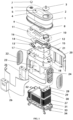
FIG. 1 is an exploded view of the structure of a high-efficiency oxyhydrogen generation device for medical care of the present invention. -
FIG. 2 is an exploded view of the structure of an electrolytic cell with heat dissipation fins of the present invention. -
FIG. 3 is an exploded view of the structure of a fan assembly of the present invention. -
FIG. 4 is a schematic diagram of the structure of a gas guide plate of the present invention. -
FIG. 5 is a partial sectional view of the high-efficiency oxyhydrogen generation device for medical care of the present invention. -
FIG. 6 is a sectional view of the structure of a secondary water tank of the present invention. -
FIG. 7 is a schematic diagram of the structure of an electric stack in a combination of serial and parallel connection according to the present invention. - In the
figures: 1 . upper cover; 2. atomization port; 3. atomization cover; 4. control panel; 5. power button; 6. water injection port; 7. sealing cover of water injection port; 8. side plate sealing element; 9. circuit board; 10. atomization chamber; 11. fixing plate; 12. atomizer; 13. gas guide plate; 14. second gas guide groove; 15. first gas guide groove; 16. sealing cover of gas guide groove; 17. cooling plate; 18. water supply tank upper cover; 19. metal probe of water level detector; 20. housing; 21. pull rod; 22. heat dissipation opening; 23. water supply tank; 24. fan assembly; 25. secondary water tank base; 26. secondary water tank; 27. electrolytic cell with heat dissipation fins; 28. gas outlet pipe; 29. pressure sensor; 30. metal probe insertion port; 31. fixing bracket; 32. safety valve; 33. bottom cover; 34. casters; 35. electrolytic tank; 36. electrolytic stack; 37. heat dissipation fins; 38. upper cover of electrolytic tank; 39. liquid injection port of electrolytic cell; 40. fan fixing bracket; 41. fan; 42. wind direction guide groove; 43. first gas outlet; 44. first gas inlet; 45. third gas outlet; 46. third gas inlet; 47. sixth gas outlet; 48. water injection channel; 49. second gas inlet; 50. second gas outlet; 51. drainage opening of electrolytic cell; 52. drainage opening of water supply tank; 53. fourth gas inlet; 54. fourth gas outlet; 55. fifth gas outlet. - It should be noted that, in the case of no conflicts, the embodiments and the features in the embodiments of the present invention can be combined mutually. The present invention will be described in detail below with reference to the accompanying drawings and the embodiments.
- To make the objectives, technical solutions and advantages of embodiments of the present disclosure more obvious, the technical solutions of the present disclosure will be clearly and completely described below in conjunction with the accompanying drawings in the embodiments of the present disclosure, and obviously, the described embodiments are some, rather than all of the embodiments of the present disclosure. The following description of at least one example embodiment is merely illustrative in nature, and is in no way intended to limit the present disclosure, an application or use thereof. Based on the embodiments of the present disclosure, all other embodiments acquired by those ordinary skilled in the art without making creative efforts fall within the scope of protection of the present disclosure.
- It should be noted that the terms used herein are only intended to describe specific embodiments and are not intended to limit the example embodiments of the present disclosure. As used herein, unless indicated obviously in the context, a singular form is also intended to include a plural form. In addition, it should also be understood that the terms "include" and/or "comprise" used in this specification indicate features, steps, operations, devices, components and/or their combinations.
- Except as otherwise specifically set forth, the relative arrangement of components and steps, numerical expressions and numerical values set forth in these embodiments do not limit the scope of the present invention. In addition, it should be clear that, for ease of description, sizes of the various components shown in the accompanying drawings are not drawn according to actual proportional relationships. Technologies, methods, and devices known to those of ordinary skill in the relevant fields may not be discussed in detail, but where appropriate, the technologies, methods, and devices should be considered as a part of the authorization specification. In all the examples shown and discussed herein, any specific value should be interpreted as merely example rather than limiting. Therefore, other examples of the example embodiments may have different values. It should be noted that similar reference signs and letters represent similar items in the accompanying drawings below. Therefore, once an item is defined in one accompanying drawing, the item does not need to be further discussed in a subsequent accompanying drawing.
- In the description of the present invention, it should be noted that orientations or position relationships indicated by orientation terms "front, rear, upper, lower, left, and right", "transverse, vertical, perpendicular, and horizontal", "top and bottom", and the like are usually based on orientations or position relationships shown in the accompanying drawings, and these terms are only used to facilitate description of the present invention and simplification of the description. In the absence of description to the contrary, these orientation terms do not indicate or imply that the apparatus or element referred to must have a specific orientation or be constructed and operated in a specific orientation, and therefore cannot be understood as a limitation on the protection scope of the present invention: orientation words "inner and outer" refer to the inside and outside relative to the contour of each component.
- For ease of description, spatially relative terms such as "on", "over", "on the upper surface", and "above" can be used here, to describe a spatial positional relationship between one device or feature and another device or feature shown in the figures. It should be understood that the spatially relative terms are intended to include different orientations in use or operation other than the orientation of the device described in the figure. For example, if the device in the figure is inverted, the device described as "above another device or structure" or "on another device or structure" is then be positioned as being "below another device or structure" or "beneath a device or structure". Therefore, the exemplary term "above" can include both orientations "above" and "below". The device can also be positioned in other different ways (rotating by 90 degrees or in another orientation), and the spatially relative description used herein is explained accordingly.
- In addition, it should be noted that using terms such as "first-stage" and "second-stage" to define components is only for the convenience of distinguishing the corresponding components. Unless otherwise stated, the foregoing words have no special meaning and therefore cannot be understood as a limitation on the protection scope of the present invention.
- As shown in
FIG. 1 , the present invention provides a high-efficiency oxyhydrogen generation device for medical care, where the main frame thereof mainly includes ahousing 20, anupper cover 1, and abottom cover 33. Thehousing 20 is composed of front and rear parts and thebottom cover 33 is fastened at the bottom of the housing to form a space for accommodating an electrolytic cell, awater supply tank 23, a water supply tankupper cover 18, and asecondary water tank 26. Theupper cover 1 fastened to the upper part of the housing, and is provided with an atomized gas circulation part, a supply part for supplying water to the water supply tank, and acontrol panel 4 for controlling the operation of an electrolyzing water hydrogen-oxygen generator. - The
water supply tank 23 is provided with the water supply tankupper cover 18, an accommodating space is disposed inside the water supply tankupper cover 18, and theupper cover 1 is sleeved on the outer side of the water supply tankupper cover 18 and is fastened to thehousing 20. Anair guide plate 13, acircuit board 9 connected to thecontrol panel 4, anatomizer 12, and a fixingplate 11 for fixing thecircuit board 9, and theatomizer 12 are disposed in the accommodating space. The atomized gas circulation part is mainly composed of theatomizer 12 disposed in anatomization chamber 10 on the fixingplate 11 and anatomization cover 3 on theupper cover 1. The atomized gas is discharged from anatomization port 2 arranged on theupper cover 1. Atomization or not depends on actual needs. Apower button 5 on theupper cover 1 is configured to control the start of thecontrol panel 4, and also the operation of the entire device. Thecontrol panel 4 is capable to control the adjustment over the gas production of the entire device, to control thewater supply tank 23 to supply water to the electrolytic cell according to the feedback of a water level detector, and to control the pressure release of the electrolytic cell according to the feedback of apressure sensor 29, and to control the start of theatomizer 12, and so on. - A side
plate sealing element 8 is further disposed between theupper cover 1 and the housing to fix and seal the two parts. - The gas guide plate 13 (as shown in
FIG. 4 ) is provided with a firstgas guide groove 15 and a secondgas guide groove 14, gas outlets/inlets are arranged at both ends of the gas guide grooves, and the structures of the gas guide grooves are rationally distributed thegas guide plate 13 according to the positions of the gas outlets. The top of the gas guide groove is sealed by a sealingcover 16 of the gas guide groove to form a gas guide chamber for gas to circulate therein. - A cooling
plate 17 is further disposed between the water supply tankupper cover 18 and thegas guiding plate 13 for cooling the generated gas. - The water supply tank
upper cover 18 is provided with a plurality of outlets/inlets corresponding to the gas outlets/inlets on thegas guide plate 12. The water supply tankupper cover 18 is further provided with awater injection channel 48 connected to awater injection port 6 arranged on theupper cover 1, to supply water to thewater supply tank 23. Thewater injection port 6 is further sealed with a sealingcover 7 of the water injection port. Further, a water pipe under thewater supply tank 23 is connected to adrainage opening 52 of the water supply tank, to empty the water stored in thewater supply tank 23. In order to monitor the water level of thewater supply tank 23, an external sensing-type water level detector for water tanks can also be used for water level monitoring. - As shown in
FIGs. 5 and 6 , thewater supply tank 23 is further provided with a device inside for generating fine air bubbles, such as an aeration device, to fully wash the gas. Similarly, thesecondary water tank 26 is also provided with a device inside for generating fine air bubbles. Thesecondary water tank 26 is used for secondary cleaning and filtering of the gas. Thesecondary water tank 26 is installed on one side of the housing through a secondarywater tank base 25. Thesecondary water tank 26 is further used as an observation window for observing the gas washing situation therein. - As shown in
FIG. 2 , the electrolytic cell that the present invention adopts is anelectrolytic cell 27 with heat dissipation fins, that is,heat dissipation fins 37 are arranged around anelectrolytic tank 35. Specifically, the electrolytic cell is arranged on thebottom cover 33 at the bottom of the housing. The electrolytic cell includes theelectrolytic tank 35, and anelectrolytic stack 36 and an electrolyte placed inside theelectrolytic tank 35. Anupper cover 38 of theelectrolytic tank 35 is provided with anair outlet pipe 28, apressure sensor 29, a metalprobe insertion port 30 of a liquid level sensor, asafety valve 32 for pressure relief, and anelectrolyte injection port 39 connected to a pump, where theelectrolyte injection port 39 supplies liquid through thewater supply tank 23. The electrolytic cell is further provided with adrainage opening 51 below, to discharge the electrolyte. The electrodes in the electrolytic stack are arranged in the serial-parallel connection mode, and in the case of low voltage input, the energy consumption is relatively low and the use is safer. In order to further fix the electrolytic cell, a fixingbracket 31 is further arranged on thebottom cover 33 to prevent the electrolytic cell from moving. - As shown in
FIG. 7 , for the electrolytic stack, compared with the serial or parallel electrode connection, the serial-parallel electrode connection mode (sharing one negative electrode) features a lower stack input voltage, and enables high gas production and relatively low energy consumption at a safe voltage (<36V). In the following table, the input voltage, input current and power in the serial-parallel mode adopted by the present invention are listed. It can be seen that at the same gas production rate, the input voltage in the serial-parallel mode is lower than that in the serial mode, the current is larger, and the energy consumption is relatively lower; and energy consumption in the serial-parallel mode is lower than that in the parallel mode.Single electrode area (cm2) Number of chambers Gas production rate (L/min) Electrode connection mode Input voltage (V) Input current (A) Power (W) 200 16 5 Serial connection 43.9 32 1404.8 200 16 5 Parallel connection 3.4 503 1710.2 200 16 5 Serial-parallel connection 22.2 63 1398.6 200 16 3 Serial connection 43.2 19 820.8 200 16 3 Parallel connection 3.2 301 963.2 200 16 3 Serial-parallel connection 21.6 38 820.8 200 16 2 Serial connection 43.4 13 564.2 200 16 2 Parallel connection 3.1 200 620 200 16 2 Serial-parallel connection 22.1 25.5 563.6 200 16 1 Serial connection 43.4 6.7 290.8 200 16 1 Parallel connection 3.1 101 313.1 200 16 1 Serial-parallel connection 22.3 13 289.9 -
Heat dissipation openings 22 for heat dissipation are arranged on both sides of the housing, and afan assembly 24 is arranged inside the housing corresponding to the heat dissipation opening (as shown inFIG. 3 ). Thefan assembly 24 includes afan 41, afan fixing bracket 40, and a wind direction guidegroove 42 arranged at the front end of thefan 41, where the wind direction guidegroove 42 faces one side of the electrolytic cell and has a gradually expanded opening used for introducing more air to better dissipate heat of the electrolytic cell. - To better achieve portability, the lower end of the
bottom cover 33 is provided withcasters 34, and the housing is further provided with apull rod 21. - The process of using the high-efficiency oxyhydrogen generating device for medical care of the present invention is as follows:
- Preparing: open the sealing
cover 7 of the water injection port, add an appropriate amount of water to the oxyhydrogen generation device, power on, turn on the power switch (arranged at the bottom of the housing to power the device) on the housing, and then turn on thepower button 5 on the upper cover to start the device. - The oxyhydrogen generated by the electrolytic cell is discharged into a
first gas outlet 43 of the gas guide plate through thegas outlet pipe 28, and then is introduced into afirst gas inlet 44 to enter asecond gas inlet 49 through the firstgas guide groove 15, and then is fully contacted with the water in thewater supply tank 23 through asecond gas outlet 50 of the aeration device, to achieve primary cleaning and filtering. The filtered gas is discharged through athird gas outlet 45, enters afourth gas inlet 53 of thesecondary water tank 26 from athird gas inlet 46 after passing through the secondgas guide groove 14, then enters the aeration device of thesecondary water tank 26, is fully contacted with the water in the secondary water tank for cleaning and filtering after passing through afourth gas outlet 54, is discharged from afifth gas outlet 55, then enters a flame arrester through asixth gas outlet 47, then enters theatomizer 12, and finally is discharged from theatomization port 2. - When the oxyhydrogen generation device works, the
metal probe 19 of the water level detector monitors the height of the electrolyte in the electrolytic cell in real time. When the electrolyte height is reduced to a preset threshold, thewater supply tank 23 is started to supply water to ensure the normal operation of the device. - The oxyhydrogen produced by the electrolysis of the electrolytic cell of the present invention flows into the
water supply tank 23 through thegas outlet pipe 28 and the firstgas guide groove 15 on thegas guide plate 13 in theupper cover 18 of the water supply tank for the purpose of primary cleaning, and then enters thesecondary water tank 26 after passing through the secondgas guide groove 14 on thegas guide plate 13 for secondary cleaning. The cleaned gas can be optionally discharged from the atomized gas circulation part through theatomizer 12 or directly discharged for use by users. - Finally, it should be noted that the above embodiments are only used to illustrate the technical solutions of the present invention, but not to limit them; although the present invention has been described in detail with reference to the foregoing embodiments, those ordinarily skilled in the art should understand that: the technical solutions described in the foregoing embodiments can still be modified, or some or all of the technical features thereof can be equivalently replaced; and these modifications or replacements do not make the essence of the corresponding technical solutions deviate from the scope of the technical solutions of the embodiments of the present invention.
Claims (10)
- A high-efficiency oxyhydrogen generation device for medical care, comprising:a housing configured to hold an electrolytic cell, a water supply tank, and a secondary water tank;an upper cover fastened to an upper part of the housing and provided with a gas circulation part, a supply part for supplying water to the water supply tank and a control panel for controlling the operation of an electrolyzing water hydrogen-oxygen generator;a bottom cover fastened to an bottom of the housing;wherein,the water supply tank is provided with a water supply tank upper cover, an accommodating space is disposed inside the water supply tank upper cover, the upper cover is sleeved on the outer side of the water supply tank upper cover and is fastened to the housing, and an air guide plate, a circuit board, an atomizer, and a fixing plate for fixing the circuit board are disposed in the accommodating space;the electrolytic cell is disposed on the bottom cover at the bottom of the housing, and is connected to the water supply tank thereabove through a pipeline, the oxyhydrogen generated by the electrolysis of the electrolytic cell passes through a gas outlet pipe and the air guide plate in the water supply tank upper cover to enter the water supply tank for primary cleaning, and then enters the secondary water tank through the air guide plate for secondary cleaning, and the cleaned gas is discharged from the gas circulation part.
- The high-efficiency oxyhydrogen generation device for medical care according to claim 1, wherein the electrolytic cell is an electrolytic cell with heat dissipation fins, and comprises an electrolytic tank, and an electrolytic stack and an electrolyte placed inside the electrolytic tank, and the electrodes in the electrolytic stack are disposed in a serial-parallel connection mode.
- The high-efficiency oxyhydrogen generation device for medical care according to claim 2, wherein the electrolytic tank is provided with a gas outlet pipe, a pressure sensor, a metal probe insertion port of a liquid level sensor, a safety valve, and a water injection port connected to a pump, wherein the water injection port is connected to the water supply tank through a pipeline.
- The high-efficiency oxyhydrogen generation device for medical care according to claim 2, wherein the heat dissipation fins are disposed around the electrolytic tank, heat dissipation openings for heat dissipation are disposed on both sides of the housing, and a fan assembly is disposed inside the housing corresponding to each the heat dissipation opening.
- The high-efficiency oxyhydrogen generation device for medical care according to claim 1, wherein two gas guide grooves are disposed on the air guide plate, a gas outlet and a gas inlet are disposed at both ends of each the gas guide groove, and a gas guide groove sealing cover is disposed on each the gas guide groove.
- The high-efficiency oxyhydrogen generation device for medical care according to claim 1, wherein each of the water supply tank and the secondary water tank is further provided with a device for generating fine bubbles.
- The high-efficiency oxyhydrogen generation device for medical care according to claim 1, wherein the secondary water tank is installed on one side of the housing through a secondary water tank base, and the secondary water tank is further used as an observation window for observing the gas washing situation therein.
- The high-efficiency oxyhydrogen generation device for medical care according to claim 1, wherein an atomizer is fixed on the fixing plate, and the gas after secondary washing is discharged from the gas circulation part after optionally passing through the atomizer.
- The high-efficiency oxyhydrogen generation device for medical care according to claim 4, wherein the fan assembly comprises a fan, a fan fixing bracket, and a wind direction guide groove disposed at the front end of the fan.
- A method for using the high-efficiency oxyhydrogen generation device for medical care according to any one of claims 1 to 9, wherein the oxyhydrogen generation device is started after adding an appropriate amount of water; oxyhydrogen generated by the electrolytic cell is discharged into an gas guide channel on the air guide plate through the gas outlet pipe and enters the water supply tank for primary cleaning, and then enters the secondary water tank through the gas guide plate for secondary cleaning, and the cleaned gas is directly discharged from the gas circulation part or discharged after passing through the atomizer.
Applications Claiming Priority (3)
| Application Number | Priority Date | Filing Date | Title |
|---|---|---|---|
| CN202122773182.4U CN216514165U (en) | 2021-11-12 | 2021-11-12 | High-efficiency hydrogen-oxygen mixed gas generating device for medical care |
| CN202111341489.5A CN116121774A (en) | 2021-11-12 | 2021-11-12 | High-efficiency oxyhydrogen mixed gas generating device for medical care and method thereof |
| PCT/CN2021/133946 WO2023082363A1 (en) | 2021-11-12 | 2021-11-29 | Efficient oxyhydrogen generation device for medical care, and method therefor |
Publications (2)
| Publication Number | Publication Date |
|---|---|
| EP4332271A1 true EP4332271A1 (en) | 2024-03-06 |
| EP4332271A4 EP4332271A4 (en) | 2025-06-11 |
Family
ID=86335034
Family Applications (1)
| Application Number | Title | Priority Date | Filing Date |
|---|---|---|---|
| EP21963805.3A Pending EP4332271A4 (en) | 2021-11-12 | 2021-11-29 | EFFICIENT HYDROGEN GAS GENERATING DEVICE FOR MEDICAL CARE AND METHOD THEREFOR |
Country Status (4)
| Country | Link |
|---|---|
| US (1) | US20240240329A1 (en) |
| EP (1) | EP4332271A4 (en) |
| JP (1) | JP7686336B2 (en) |
| WO (1) | WO2023082363A1 (en) |
Families Citing this family (1)
| Publication number | Priority date | Publication date | Assignee | Title |
|---|---|---|---|---|
| CN117379297A (en) * | 2023-11-30 | 2024-01-12 | 深圳微子医疗有限公司 | Hydrogen negative ion spa machine |
Family Cites Families (12)
| Publication number | Priority date | Publication date | Assignee | Title |
|---|---|---|---|---|
| KR100275504B1 (en) * | 1998-10-23 | 2001-04-02 | 김상남 | Brown gas mass generator including row type electrolyzer |
| TW547489U (en) * | 2001-09-14 | 2003-08-11 | Shihlin Electric & Engineering | Hydrogen oxygen generation device with insertion type electrolytic tank |
| CN101565832A (en) * | 2008-04-25 | 2009-10-28 | 清华大学 | Water electrolysis hydrogen production system for solar battery |
| CN101654786B (en) * | 2009-09-11 | 2011-01-05 | 上海高企新能源科技有限公司 | Separating-cooling-washing integrated oxyhydrogen machine |
| CN202881396U (en) * | 2012-10-18 | 2013-04-17 | 王可全 | Oxy-hydrogen gas generator |
| CN103806013A (en) * | 2013-06-19 | 2014-05-21 | 林信涌 | Gas-water circulating system |
| CN108295352B (en) * | 2014-01-07 | 2019-09-27 | 上海潓美医疗科技有限公司 | health care gas generation system |
| CN105154907B (en) * | 2015-09-22 | 2017-12-08 | 中国华能集团清洁能源技术研究院有限公司 | A kind of electrolysis water oxygen generation system and method based on solid oxide electrolyte |
| JP2018118188A (en) * | 2017-01-23 | 2018-08-02 | エムズジャパン株式会社 | Hydrogen/oxygen mixed gas generating device and hydrogen/oxygen mixed gas generating method |
| CN213925044U (en) * | 2020-08-04 | 2021-08-10 | 济南格润实验仪器有限公司 | SPE proton membrane hydrogen-oxygen mixed generator |
| CN214088680U (en) * | 2020-12-15 | 2021-08-31 | 中国科学院大连化学物理研究所 | Compact portable oxyhydrogen instrument |
| CN112501633A (en) * | 2020-12-28 | 2021-03-16 | 陕西华秦新能源科技有限责任公司 | Large-gas-production-rate oxyhydrogen generator and use method thereof |
-
2021
- 2021-11-29 US US18/556,700 patent/US20240240329A1/en active Pending
- 2021-11-29 EP EP21963805.3A patent/EP4332271A4/en active Pending
- 2021-11-29 WO PCT/CN2021/133946 patent/WO2023082363A1/en not_active Ceased
- 2021-11-29 JP JP2024518118A patent/JP7686336B2/en active Active
Also Published As
| Publication number | Publication date |
|---|---|
| WO2023082363A1 (en) | 2023-05-19 |
| US20240240329A1 (en) | 2024-07-18 |
| JP2024535325A (en) | 2024-09-30 |
| JP7686336B2 (en) | 2025-06-02 |
| EP4332271A4 (en) | 2025-06-11 |
Similar Documents
| Publication | Publication Date | Title |
|---|---|---|
| CN108624903A (en) | Electrolytic water device | |
| CN108624901A (en) | Electrolytic water device | |
| KR101732117B1 (en) | Desktop Hydrogen Gas Generation Device | |
| CN208008909U (en) | Electrolytic water device | |
| CN103789788A (en) | Gas generator | |
| CN106637280B (en) | The pressurization electrolytic cell core and the generator containing the pressurization electrolytic cell core of a kind of hydrogen-rich water | |
| CN105879098A (en) | Hydrogen-rich hydrogen water atomization device | |
| CN107349094A (en) | A kind of hydrogen-rich bubble bathing device | |
| CN216514165U (en) | High-efficiency hydrogen-oxygen mixed gas generating device for medical care | |
| US20240240329A1 (en) | High-efficiency oxyhydrogen generation device for medical care and using method thereof | |
| CN210644797U (en) | Gas supply system of hydrogen breathing machine and gas control valve thereof | |
| CN216294947U (en) | Hydrogen absorption machine | |
| RU2838998C2 (en) | Device for generating oxyhydrogen for medical care and method of using same | |
| CN223047343U (en) | Hydrogen-rich water machine with integrated structure of drinking water and bathing | |
| CN116121774A (en) | High-efficiency oxyhydrogen mixed gas generating device for medical care and method thereof | |
| CN211326741U (en) | Hydrogen-rich bathing machine | |
| WO2024155843A1 (en) | Method and system for generating a gas mixture | |
| CN211560814U (en) | Hydrogen physical therapy cabin | |
| CN215607545U (en) | Beauty instrument | |
| CN216294919U (en) | Oxyhydrogen breathing machine with low frequency generation module | |
| CN214996364U (en) | Novel automatic control personnel disinfection channel | |
| CN213538114U (en) | Multi-core high-efficiency hydrogen and oxygen generator | |
| CN212395378U (en) | Hydrogen-rich water bathing system | |
| TWI642811B (en) | Water electrolysis device | |
| CN221371296U (en) | Deodorization sterilizer for public sanitary place |
Legal Events
| Date | Code | Title | Description |
|---|---|---|---|
| STAA | Information on the status of an ep patent application or granted ep patent |
Free format text: STATUS: THE INTERNATIONAL PUBLICATION HAS BEEN MADE |
|
| PUAI | Public reference made under article 153(3) epc to a published international application that has entered the european phase |
Free format text: ORIGINAL CODE: 0009012 |
|
| STAA | Information on the status of an ep patent application or granted ep patent |
Free format text: STATUS: REQUEST FOR EXAMINATION WAS MADE |
|
| 17P | Request for examination filed |
Effective date: 20231129 |
|
| AK | Designated contracting states |
Kind code of ref document: A1 Designated state(s): AL AT BE BG CH CY CZ DE DK EE ES FI FR GB GR HR HU IE IS IT LI LT LU LV MC MK MT NL NO PL PT RO RS SE SI SK SM TR |
|
| DAV | Request for validation of the european patent (deleted) | ||
| DAX | Request for extension of the european patent (deleted) | ||
| A4 | Supplementary search report drawn up and despatched |
Effective date: 20250512 |
|
| RIC1 | Information provided on ipc code assigned before grant |
Ipc: A61M 16/00 20060101ALI20250506BHEP Ipc: C01B 13/02 20060101ALI20250506BHEP Ipc: C25B 15/023 20210101ALI20250506BHEP Ipc: C25B 9/73 20210101ALI20250506BHEP Ipc: C25B 15/08 20060101ALI20250506BHEP Ipc: C25B 9/67 20210101ALI20250506BHEP Ipc: C25B 9/17 20210101ALI20250506BHEP Ipc: A61M 16/10 20060101ALI20250506BHEP Ipc: C25B 1/044 20210101AFI20250506BHEP |