EP4332060A1 - Method for manufacturing carbon nanotube dispersion - Google Patents
Method for manufacturing carbon nanotube dispersion Download PDFInfo
- Publication number
- EP4332060A1 EP4332060A1 EP22833406.6A EP22833406A EP4332060A1 EP 4332060 A1 EP4332060 A1 EP 4332060A1 EP 22833406 A EP22833406 A EP 22833406A EP 4332060 A1 EP4332060 A1 EP 4332060A1
- Authority
- EP
- European Patent Office
- Prior art keywords
- carbon nanotube
- nanotube dispersion
- preparing
- present disclosure
- post
- Prior art date
- Legal status (The legal status is an assumption and is not a legal conclusion. Google has not performed a legal analysis and makes no representation as to the accuracy of the status listed.)
- Pending
Links
Images


Classifications
-
- C—CHEMISTRY; METALLURGY
- C01—INORGANIC CHEMISTRY
- C01B—NON-METALLIC ELEMENTS; COMPOUNDS THEREOF; METALLOIDS OR COMPOUNDS THEREOF NOT COVERED BY SUBCLASS C01C
- C01B32/00—Carbon; Compounds thereof
- C01B32/15—Nano-sized carbon materials
- C01B32/158—Carbon nanotubes
- C01B32/168—After-treatment
- C01B32/174—Derivatisation; Solubilisation; Dispersion in solvents
-
- C—CHEMISTRY; METALLURGY
- C01—INORGANIC CHEMISTRY
- C01B—NON-METALLIC ELEMENTS; COMPOUNDS THEREOF; METALLOIDS OR COMPOUNDS THEREOF NOT COVERED BY SUBCLASS C01C
- C01B32/00—Carbon; Compounds thereof
- C01B32/15—Nano-sized carbon materials
- C01B32/158—Carbon nanotubes
- C01B32/16—Preparation
- C01B32/162—Preparation characterised by catalysts
-
- C—CHEMISTRY; METALLURGY
- C09—DYES; PAINTS; POLISHES; NATURAL RESINS; ADHESIVES; COMPOSITIONS NOT OTHERWISE PROVIDED FOR; APPLICATIONS OF MATERIALS NOT OTHERWISE PROVIDED FOR
- C09C—TREATMENT OF INORGANIC MATERIALS, OTHER THAN FIBROUS FILLERS, TO ENHANCE THEIR PIGMENTING OR FILLING PROPERTIES ; PREPARATION OF CARBON BLACK ; PREPARATION OF INORGANIC MATERIALS WHICH ARE NO SINGLE CHEMICAL COMPOUNDS AND WHICH ARE MAINLY USED AS PIGMENTS OR FILLERS
- C09C1/00—Treatment of specific inorganic materials other than fibrous fillers; Preparation of carbon black
- C09C1/44—Carbon
-
- C—CHEMISTRY; METALLURGY
- C09—DYES; PAINTS; POLISHES; NATURAL RESINS; ADHESIVES; COMPOSITIONS NOT OTHERWISE PROVIDED FOR; APPLICATIONS OF MATERIALS NOT OTHERWISE PROVIDED FOR
- C09D—COATING COMPOSITIONS, e.g. PAINTS, VARNISHES OR LACQUERS; FILLING PASTES; CHEMICAL PAINT OR INK REMOVERS; INKS; CORRECTING FLUIDS; WOODSTAINS; PASTES OR SOLIDS FOR COLOURING OR PRINTING; USE OF MATERIALS THEREFOR
- C09D1/00—Coating compositions, e.g. paints, varnishes or lacquers, based on inorganic substances
-
- C—CHEMISTRY; METALLURGY
- C09—DYES; PAINTS; POLISHES; NATURAL RESINS; ADHESIVES; COMPOSITIONS NOT OTHERWISE PROVIDED FOR; APPLICATIONS OF MATERIALS NOT OTHERWISE PROVIDED FOR
- C09D—COATING COMPOSITIONS, e.g. PAINTS, VARNISHES OR LACQUERS; FILLING PASTES; CHEMICAL PAINT OR INK REMOVERS; INKS; CORRECTING FLUIDS; WOODSTAINS; PASTES OR SOLIDS FOR COLOURING OR PRINTING; USE OF MATERIALS THEREFOR
- C09D17/00—Pigment pastes, e.g. for mixing in paints
- C09D17/002—Pigment pastes, e.g. for mixing in paints in organic medium
-
- C—CHEMISTRY; METALLURGY
- C09—DYES; PAINTS; POLISHES; NATURAL RESINS; ADHESIVES; COMPOSITIONS NOT OTHERWISE PROVIDED FOR; APPLICATIONS OF MATERIALS NOT OTHERWISE PROVIDED FOR
- C09D—COATING COMPOSITIONS, e.g. PAINTS, VARNISHES OR LACQUERS; FILLING PASTES; CHEMICAL PAINT OR INK REMOVERS; INKS; CORRECTING FLUIDS; WOODSTAINS; PASTES OR SOLIDS FOR COLOURING OR PRINTING; USE OF MATERIALS THEREFOR
- C09D17/00—Pigment pastes, e.g. for mixing in paints
- C09D17/004—Pigment pastes, e.g. for mixing in paints containing an inorganic pigment
-
- C—CHEMISTRY; METALLURGY
- C09—DYES; PAINTS; POLISHES; NATURAL RESINS; ADHESIVES; COMPOSITIONS NOT OTHERWISE PROVIDED FOR; APPLICATIONS OF MATERIALS NOT OTHERWISE PROVIDED FOR
- C09D—COATING COMPOSITIONS, e.g. PAINTS, VARNISHES OR LACQUERS; FILLING PASTES; CHEMICAL PAINT OR INK REMOVERS; INKS; CORRECTING FLUIDS; WOODSTAINS; PASTES OR SOLIDS FOR COLOURING OR PRINTING; USE OF MATERIALS THEREFOR
- C09D7/00—Features of coating compositions, not provided for in group C09D5/00; Processes for incorporating ingredients in coating compositions
- C09D7/20—Diluents or solvents
-
- C—CHEMISTRY; METALLURGY
- C09—DYES; PAINTS; POLISHES; NATURAL RESINS; ADHESIVES; COMPOSITIONS NOT OTHERWISE PROVIDED FOR; APPLICATIONS OF MATERIALS NOT OTHERWISE PROVIDED FOR
- C09D—COATING COMPOSITIONS, e.g. PAINTS, VARNISHES OR LACQUERS; FILLING PASTES; CHEMICAL PAINT OR INK REMOVERS; INKS; CORRECTING FLUIDS; WOODSTAINS; PASTES OR SOLIDS FOR COLOURING OR PRINTING; USE OF MATERIALS THEREFOR
- C09D7/00—Features of coating compositions, not provided for in group C09D5/00; Processes for incorporating ingredients in coating compositions
- C09D7/40—Additives
- C09D7/60—Additives non-macromolecular
- C09D7/61—Additives non-macromolecular inorganic
-
- C—CHEMISTRY; METALLURGY
- C09—DYES; PAINTS; POLISHES; NATURAL RESINS; ADHESIVES; COMPOSITIONS NOT OTHERWISE PROVIDED FOR; APPLICATIONS OF MATERIALS NOT OTHERWISE PROVIDED FOR
- C09D—COATING COMPOSITIONS, e.g. PAINTS, VARNISHES OR LACQUERS; FILLING PASTES; CHEMICAL PAINT OR INK REMOVERS; INKS; CORRECTING FLUIDS; WOODSTAINS; PASTES OR SOLIDS FOR COLOURING OR PRINTING; USE OF MATERIALS THEREFOR
- C09D7/00—Features of coating compositions, not provided for in group C09D5/00; Processes for incorporating ingredients in coating compositions
- C09D7/40—Additives
- C09D7/70—Additives characterised by shape, e.g. fibres, flakes or microspheres
-
- H—ELECTRICITY
- H01—ELECTRIC ELEMENTS
- H01G—CAPACITORS; CAPACITORS, RECTIFIERS, DETECTORS, SWITCHING DEVICES, LIGHT-SENSITIVE OR TEMPERATURE-SENSITIVE DEVICES OF THE ELECTROLYTIC TYPE
- H01G11/00—Hybrid capacitors, i.e. capacitors having different positive and negative electrodes; Electric double-layer [EDL] capacitors; Processes for the manufacture thereof or of parts thereof
- H01G11/22—Electrodes
- H01G11/30—Electrodes characterised by their material
- H01G11/32—Carbon-based
- H01G11/36—Nanostructures, e.g. nanofibres, nanotubes or fullerenes
-
- H—ELECTRICITY
- H01—ELECTRIC ELEMENTS
- H01G—CAPACITORS; CAPACITORS, RECTIFIERS, DETECTORS, SWITCHING DEVICES, LIGHT-SENSITIVE OR TEMPERATURE-SENSITIVE DEVICES OF THE ELECTROLYTIC TYPE
- H01G11/00—Hybrid capacitors, i.e. capacitors having different positive and negative electrodes; Electric double-layer [EDL] capacitors; Processes for the manufacture thereof or of parts thereof
- H01G11/84—Processes for the manufacture of hybrid or EDL capacitors, or components thereof
- H01G11/86—Processes for the manufacture of hybrid or EDL capacitors, or components thereof specially adapted for electrodes
-
- H—ELECTRICITY
- H01—ELECTRIC ELEMENTS
- H01M—PROCESSES OR MEANS, e.g. BATTERIES, FOR THE DIRECT CONVERSION OF CHEMICAL ENERGY INTO ELECTRICAL ENERGY
- H01M4/00—Electrodes
- H01M4/02—Electrodes composed of, or comprising, active material
- H01M4/62—Selection of inactive substances as ingredients for active masses, e.g. binders, fillers
- H01M4/624—Electric conductive fillers
- H01M4/625—Carbon or graphite
-
- B—PERFORMING OPERATIONS; TRANSPORTING
- B82—NANOTECHNOLOGY
- B82Y—SPECIFIC USES OR APPLICATIONS OF NANOSTRUCTURES; MEASUREMENT OR ANALYSIS OF NANOSTRUCTURES; MANUFACTURE OR TREATMENT OF NANOSTRUCTURES
- B82Y30/00—Nanotechnology for materials or surface science, e.g. nanocomposites
-
- B—PERFORMING OPERATIONS; TRANSPORTING
- B82—NANOTECHNOLOGY
- B82Y—SPECIFIC USES OR APPLICATIONS OF NANOSTRUCTURES; MEASUREMENT OR ANALYSIS OF NANOSTRUCTURES; MANUFACTURE OR TREATMENT OF NANOSTRUCTURES
- B82Y40/00—Manufacture or treatment of nanostructures
-
- C—CHEMISTRY; METALLURGY
- C01—INORGANIC CHEMISTRY
- C01B—NON-METALLIC ELEMENTS; COMPOUNDS THEREOF; METALLOIDS OR COMPOUNDS THEREOF NOT COVERED BY SUBCLASS C01C
- C01B2202/00—Structure or properties of carbon nanotubes
- C01B2202/20—Nanotubes characterized by their properties
- C01B2202/22—Electronic properties
-
- C—CHEMISTRY; METALLURGY
- C01—INORGANIC CHEMISTRY
- C01B—NON-METALLIC ELEMENTS; COMPOUNDS THEREOF; METALLOIDS OR COMPOUNDS THEREOF NOT COVERED BY SUBCLASS C01C
- C01B2202/00—Structure or properties of carbon nanotubes
- C01B2202/20—Nanotubes characterized by their properties
- C01B2202/32—Specific surface area
-
- C—CHEMISTRY; METALLURGY
- C01—INORGANIC CHEMISTRY
- C01B—NON-METALLIC ELEMENTS; COMPOUNDS THEREOF; METALLOIDS OR COMPOUNDS THEREOF NOT COVERED BY SUBCLASS C01C
- C01B2202/00—Structure or properties of carbon nanotubes
- C01B2202/20—Nanotubes characterized by their properties
- C01B2202/36—Diameter
-
- C—CHEMISTRY; METALLURGY
- C01—INORGANIC CHEMISTRY
- C01P—INDEXING SCHEME RELATING TO STRUCTURAL AND PHYSICAL ASPECTS OF SOLID INORGANIC COMPOUNDS
- C01P2004/00—Particle morphology
- C01P2004/01—Particle morphology depicted by an image
- C01P2004/03—Particle morphology depicted by an image obtained by SEM
-
- C—CHEMISTRY; METALLURGY
- C01—INORGANIC CHEMISTRY
- C01P—INDEXING SCHEME RELATING TO STRUCTURAL AND PHYSICAL ASPECTS OF SOLID INORGANIC COMPOUNDS
- C01P2004/00—Particle morphology
- C01P2004/60—Particles characterised by their size
- C01P2004/61—Micrometer sized, i.e. from 1-100 micrometer
-
- C—CHEMISTRY; METALLURGY
- C01—INORGANIC CHEMISTRY
- C01P—INDEXING SCHEME RELATING TO STRUCTURAL AND PHYSICAL ASPECTS OF SOLID INORGANIC COMPOUNDS
- C01P2006/00—Physical properties of inorganic compounds
- C01P2006/12—Surface area
-
- C—CHEMISTRY; METALLURGY
- C01—INORGANIC CHEMISTRY
- C01P—INDEXING SCHEME RELATING TO STRUCTURAL AND PHYSICAL ASPECTS OF SOLID INORGANIC COMPOUNDS
- C01P2006/00—Physical properties of inorganic compounds
- C01P2006/22—Rheological behaviour as dispersion, e.g. viscosity, sedimentation stability
-
- C—CHEMISTRY; METALLURGY
- C08—ORGANIC MACROMOLECULAR COMPOUNDS; THEIR PREPARATION OR CHEMICAL WORKING-UP; COMPOSITIONS BASED THEREON
- C08K—Use of inorganic or non-macromolecular organic substances as compounding ingredients
- C08K2201/00—Specific properties of additives
- C08K2201/002—Physical properties
- C08K2201/003—Additives being defined by their diameter
-
- C—CHEMISTRY; METALLURGY
- C08—ORGANIC MACROMOLECULAR COMPOUNDS; THEIR PREPARATION OR CHEMICAL WORKING-UP; COMPOSITIONS BASED THEREON
- C08K—Use of inorganic or non-macromolecular organic substances as compounding ingredients
- C08K2201/00—Specific properties of additives
- C08K2201/002—Physical properties
- C08K2201/006—Additives being defined by their surface area
-
- C—CHEMISTRY; METALLURGY
- C08—ORGANIC MACROMOLECULAR COMPOUNDS; THEIR PREPARATION OR CHEMICAL WORKING-UP; COMPOSITIONS BASED THEREON
- C08K—Use of inorganic or non-macromolecular organic substances as compounding ingredients
- C08K2201/00—Specific properties of additives
- C08K2201/011—Nanostructured additives
-
- C—CHEMISTRY; METALLURGY
- C08—ORGANIC MACROMOLECULAR COMPOUNDS; THEIR PREPARATION OR CHEMICAL WORKING-UP; COMPOSITIONS BASED THEREON
- C08K—Use of inorganic or non-macromolecular organic substances as compounding ingredients
- C08K3/00—Use of inorganic substances as compounding ingredients
- C08K3/02—Elements
- C08K3/04—Carbon
- C08K3/041—Carbon nanotubes
Definitions
- the present disclosure relates to a method for preparing a carbon nanotube dispersion.
- Carbon nanotubes may have excellent mechanical robustness and chemical stability, have both semiconductor and conductor properties, and have small diameters, large lengths, and hollow properties, and thus are suitable as materials for flat panel displays, transistors, energy storage media, etc. and have high potential for application as various nano-sized electronic devices.
- the carbon nanotubes In order to use carbon nanotubes for forming conductive films or manufacturing various other electronic devices, the carbon nanotubes need to be effectively dispersed in a matrix such as a solvent or binder. However, the carbon nanotubes have a strong tendency to aggregate into bundles within the matrix due to strong Van der Waals forces and thus have a disadvantage of making processing difficult due to very low solubility in water or other solvents.
- the carbon nanotubes aggregate within the matrix, there may be problems that the unique properties of the carbon nanotubes may not be exhibited, or the uniformity of thin film properties deteriorates when manufactured as a thin film.
- the dispersion of carbon nanotubes is more important in display applications where transparency needs to be secured, like the case of using a transistor as a semiconductor material or an electrode as a conductor material.
- carbon nanotube strands are not completely separated but aggregate in bundles, so that the desired transmittance cannot be secured even if the same performance is achieved.
- carbon nanotubes used in a conventional method of preparing a carbon nanotube dispersion tend to rapidly increase and then decrease in viscosity of the dispersion as the dispersion energy increases, and such an irregular change in viscosity increases variables in the preparing process of the carbon nanotube dispersion to cause problems in efficiently preparing the dispersion.
- process efficiency may be increased.
- Korean Patent Registration No. 10-1807798 relates to a carbon nanotube dispersion and a preparing method thereof.
- Korean Patent Registration No. 10-1807798 there is disclosed a method for preparing a carbon nanotube dispersion with excellent dispersibility, dispersion stability and adhesion, but it is not disclosed to have a predictable viscosity tendency using carbon nanotubes of which an average length is controlled.
- An object to be achieved by the present disclosure is to provide a method for preparing a carbon nanotube dispersion having a predictable viscosity tendency during a dispersion process by controlling an average length of carbon nanotubes.
- Another object to be achieved by the present disclosure is to provide a carbon nanotube dispersion prepared by the preparing method.
- Yet another object to be achieved by the present disclosure is to provide an energy storage device including the carbon nanotube dispersion.
- Yet another object to be achieved by the present disclosure is to provide a composite material including the carbon nanotube dispersion.
- Yet another object to be achieved by the present disclosure is to provide a pigment including the carbon nanotube dispersion.
- Yet another object to be achieved by the present disclosure is to provide a paint including the carbon nanotube dispersion.
- a method for preparing a carbon nanotube dispersion including preparing a carbon nanotube bundle; post-processing the carbon nanotube bundle to reduce an average length of the carbon nanotube bundle to 50 ⁇ m or less; and dispersing the post-processed carbon nanotube bundle in a solution.
- a volume-average (cumulative) diameter Dv(90) of the post-processed carbon nanotube bundle may be 50 ⁇ m, but is not limited thereto.
- the solution may include a solvent and a dispersant, but is not limited thereto.
- the solvent may be selected from the group consisting of deionized water, N-methyl-2-pyrrolidone, N,N-dimethylformamide, N,N-dimethylacetamide, dimethyl sulfoxide, ethanol, methanol, pentyl alcohol, acetone, methyl ethyl ketone, cyclopentanone, ethyl acetate, ethylene glycol, diethylene glycol, 1-propanol, isopropanol, 1-butanol, isobutanol, octanol, ethylene glycol monoethyl ether, diethylene glycol monoethyl ether, triethylene glycol monoethyl ether, tetraethylene glycol monoethyl ether, and combinations thereof, but is not limited thereto.
- the dispersant may be selected from the group consisting of polyvinylpyrrolidone, hydrogenated nitrile rubber, polyvinyl alcohol, polyvinyl methyl ether, polyethylene glycol, polypropylene glycol, polyacrylamide, polyethylene oxide, polyethylene oxide/propylene oxide block copolymer, polyacrylic acid salts, cellulose derivatives, starch derivatives, and combinations thereof, but is not limited thereto.
- the carbon nanotubes may be prepared by chemical vapor deposition in the presence of a catalyst, but are not limited thereto.
- the carbon nanotubes may be prepared using a reaction source selected from the group consisting of acetylene, ethylene, methane, and combinations thereof, but are not limited thereto.
- the catalyst may include a catalyst selected from the group consisting of Fe, Co, Ni, Al, Mg, Mo, Si, and combinations thereof, but is not limited thereto.
- the catalyst may be prepared by a method selected from the group consisting of a combusting method, a supporting method, a probing method, a sol-gel method, and combinations thereof, but is not limited thereto.
- the dispersing step may be performed by a process selected from the group consisting of an ultrasonic process, a pulverization process by physical impact force, a pulverization process by physical shear force, a high pressure process, a supercritical/subcritical process, and combinations thereof, but is not limited thereto.
- the post-processing may include dry post-processing and/or wet post-processing, but is not limited thereto.
- the dry post-processing may be selected from the group consisting of air dry mill, bead mill, attrition mill, jet mill, steam jet mill, and combinations thereof, but is not limited thereto.
- the wet post-processing may be selected from the group consisting of bead mill, attrition mill, sonication, shear mill, high pressure homogenizer, mechanical homogenizer and combinations thereof, but is not limited thereto.
- the post-processed carbon nanotubes may have a specific surface area of 50 cm 2 /g or more and a diameter of 1 nm or more, but are not limited thereto.
- a carbon nanotube dispersion prepared by the method according to the first aspect of the present disclosure, in which a saturation point according to the dispersion energy of a viscosity ( ⁇ ) of the carbon nanotube dispersion is proportional to an average length value of the post-processed carbon nanotubes.
- an energy storage device including the carbon nanotube dispersion according to the second aspect of the present disclosure.
- a composite material including the carbon nanotube dispersion according to the second aspect of the present disclosure is provided.
- a pigment including the carbon nanotube dispersion according to the second aspect of the present disclosure is provided.
- a paint including the carbon nanotube dispersion according to the second aspect of the present disclosure there is provided a paint including the carbon nanotube dispersion according to the second aspect of the present disclosure.
- the method for preparing the carbon nanotube dispersion according to the present disclosure it is possible to predict and improve efficiency of the carbon nanotube dispersion process using material properties according to the length of the carbon nanotubes, and input dispersion energy and viscosity properties according to the length of the carbon nanotubes.
- the dispersion is prepared by controlling the length of the carbon nanotube bundle to 50 ⁇ m or less to have a different aspect from the viscosity tendency of the conventional carbon nanotube dispersion, and to predict and improve process efficiency during the dispersion process using the viscosity tendency.
- the saturation point according to the dispersion energy of the viscosity ( ⁇ ) of the carbon nanotube dispersion according to the present disclosure is proportional to the average length of the carbon nanotubes.
- effects obtainable herein are not limited to the effects described above, and other effects may be present.
- the term "combinations thereof" included in the expression of the Markush form means one or more mixtures or combinations selected from the group consisting of components described in the expression of the Markush form, and means to include at least one selected from the group consisting of the components.
- a and/or B means “A or B, or A and B”.
- a method for preparing a carbon nanotube dispersion including preparing a carbon nanotube bundle; post-processing the carbon nanotube bundle to reduce an average length of the carbon nanotube bundle to 50 ⁇ m or less; and dispersing the post-processed carbon nanotube bundle in a solution.
- the method for preparing the carbon nanotube dispersion according to the present disclosure it is possible to predict and improve efficiency of the carbon nanotube dispersion process using material properties according to the length of the carbon nanotubes, and input dispersion energy and viscosity properties according to the length of the carbon nanotubes.
- the dispersion by preparing the dispersion by controlling the length of the carbon nanotube bundle to 50 ⁇ m or less, unlike the viscosity tendency of the conventional carbon nanotube dispersion, as dispersion energy is applied, there is a point where the viscosity is increased and then saturated, and a saturation point according to the dispersion energy of the viscosity ( ⁇ ) of the carbon nanotube dispersion tends to be proportional to the average length value of the carbon nanotubes. It is possible to predict and improve process efficiency during the dispersing process using such viscosity tendency.
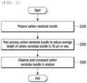
- FIG. 1 is a flowchart of a method for preparing a carbon nanotube dispersion according to an exemplary embodiment of the present disclosure.
- the carbon nanotube bundle is prepared (S100).
- the carbon nanotubes may be prepared by chemical vapor deposition in the presence of a catalyst, but are not limited thereto.
- the carbon nanotubes may be prepared using a reaction source selected from the group consisting of acetylene, ethylene, methane, and combinations thereof, but are not limited thereto.
- the catalyst may include a catalyst selected from the group consisting of Fe, Co, Ni, Al, Mg, Mo, Si, and combinations thereof, but is not limited thereto.
- the catalyst may be prepared by a method selected from the group consisting of a combusting method, a supporting method, a probing method, a sol-gel method, and combinations thereof, but is not limited thereto.
- the average length of the carbon nanotube bundle may be controlled by performing dry post-processing and/or wet post-processing.
- the length of the carbon nanotubes is controlled by directly using the prepared carbon nanotube bundle, and then a carbon nanotube dispersion may be prepared.
- the length of the carbon nanotubes is controlled using a solution in which the carbon nanotube bundle is added to a solvent (water, ethanol, etc.), the solution is dried to be prepared in a powder state, and then the carbon nanotube dispersion may be prepared.
- a solvent water, ethanol, etc.
- the carbon nanotube bundle may be prepared in a solid phase (carbon nanotube bundle) or a liquid phase (solution containing the carbon nanotube bundle) depending on how post-processing is performed.
- the carbon nanotube bundle is post-processed to reduce the average length of the carbon nanotube bundle to 50 ⁇ m or less (S200).
- a volume-average (cumulative) diameter Dv(90) of the post-processed carbon nanotube bundle may be 50 ⁇ m, but is not limited thereto.
- the volume-average (cumulative) diameter is considered as a sphere having the same volume because the sizes of non-spherical particles may not be expressed as one value, and Dv(10) refers to a size at 10% of the entire particle size distribution, Dv(50) refers to a size at 500 of the entire particle size distribution (median value), and Dv(90) refers to a size at 90% of the entire particle size distribution.
- the volume-average (cumulative) diameter Dv(90) of 50 ⁇ m means that 90% of the particle sizes are 50 ⁇ m or less, which is able to be interpreted as the majority of the particle sizes are 50 ⁇ m or less.
- the post-processed carbon nanotubes may have a specific surface area of 50 cm 2 /g or more and a diameter of 1 nm or more, but are not limited thereto.
- the post-processing may include dry post-processing and/or wet post-processing, but is not limited thereto.
- the post-processing is performed by directly using the prepared carbon nanotube bundle, and the carbon nanotube dispersion may be prepared using the post-processed carbon nanotubes.
- the post-processing may be performed using a solution in which the carbon nanotube bundle is added to a solvent (water, ethanol, etc.), and the carbon nanotubes in which the length is controlled through the wet post-processing are dried to be prepared in a powder state, and then used for the preparation of the carbon nanotube dispersion.
- a solvent water, ethanol, etc.
- the dry post-processing may be selected from the group consisting of an air dry mill, a bead mill, an attrition mill, a jet mill, a steam jet mill, and combinations thereof, but is not limited thereto.
- the wet post-processing may be selected from the group consisting of bead mill, attrition mill, sonication, shear mill, high pressure homogenizer, mechanical homogenizer and combinations thereof, but is not limited thereto.
- the step of dispersing the post-processed carbon nanotube bundle in the solution may be further included, but is not limited thereto.
- the solution may include a solvent and a dispersant, but is not limited thereto.
- the solvent may be selected from the group consisting of deionized water, N-methyl-2-pyrrolidone, N,N-dimethylformamide, N,N-dimethylacetamide, dimethyl sulfoxide, ethanol, methanol, pentyl alcohol, acetone, methyl ethyl ketone, cyclopentanone, ethyl acetate, ethylene glycol, diethylene glycol, 1-propanol, isopropanol, 1-butanol, isobutanol, octanol, ethylene glycol monoethyl ether, diethylene glycol monoethyl ether, triethylene glycol monoethyl ether, tetraethylene glycol monoethyl ether, and combinations thereof, but is not limited thereto.
- the dispersant may be selected from the group consisting of polyvinylpyrrolidone, hydrogenated nitrile rubber, polyvinyl alcohol, polyvinyl methyl ether, polyethylene glycol, polypropylene glycol, polyacrylamide, polyethylene oxide, polyethylene oxide/propylene oxide block copolymer, polyacrylic acid salts, cellulose derivatives, starch derivatives, and combinations thereof, but is not limited thereto.
- the dispersing step may be performed by a process selected from the group consisting of an ultrasonic process, a pulverization process by physical impact force, a pulverization process by physical shear force, a high pressure process, a supercritical/subcritical process, and combinations thereof, but is not limited thereto.
- a carbon nanotube dispersion prepared by the method according to the first aspect of the present disclosure, in which a saturation point according to the dispersion energy of a viscosity ( ⁇ ) of the carbon nanotube dispersion is proportional to an average length value of the post-processed carbon nanotubes.
- the carbon nanotubes according to the present disclosure have an average length of 50 ⁇ m or less, and accordingly, have a different aspect from the tendency of the viscosity change of conventional carbon nanotubes.
- the conventional carbon nanotube dispersion increases the dispersion energy, the viscosity has been irregularly changed, but in the carbon nanotube dispersion according to the present disclosure, as the dispersion energy increases, there is a saturation point where the viscosity increases and then becomes constant, and the saturation point decreases as the average length of the carbon nanotubes decreases.
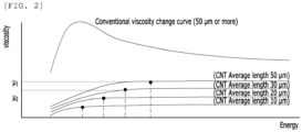
- FIG. 2 is a distributed energy-viscosity curve according to the length of carbon nanotubes according to an exemplary embodiment of the present disclosure.
- the average length of the carbon nanotubes is 50 ⁇ m or less, it may be confirmed that there is a saturation point where the viscosity increases and then becomes constant as the dispersion energy increases.
- the saturation point decreases as the average length of carbon nanotubes decreases. Accordingly, a relationship between the average length of carbon nanotubes and the viscosity of the dispersion is represented by a viscosity index of the dispersion according to the length of the carbon nanotubes, thereby predicting and improving the efficiency of the process when preparing the dispersion.
- FIG. 3 is a graph showing a viscosity index of the dispersion according to the length of carbon nanotubes according to an exemplary embodiment of the present disclosure.
- the viscosity index of the dispersion according to the length of the carbon nanotube is defined with reference to FIG. 3 .
- the viscosity may be represented as a value obtained by dividing shear stress by a shear rate.
- the shear stress is an expression of a cross-sectional area A (cm 2 ), which is a part where each fluid layer is in contact with each other when each fluid layer was considered three-dimensional.
- a constant force F (dynes) is applied to the upper part of the fluid layer, a constant force F (dynes) is generated at the contact surface of each fluid layer, that is, the cross-sectional area A (cm 2 ).
- the force received per cross-sectional area of the fluid layer is the shear stress.
- a value obtained by dividing a friction force F (dynes) by a unit area A (cm 2 ) is the shear stress F/A (dynes/cm 2 ).
- a stationary phase and a mobile phase exist at a predetermined distance X (cm), and a fluid also exists between the phases.
- the fluid When the upper plate, that is, the mobile phase is moved from the outside with a constant force, the fluid also moves at a constant velocity V (cm/sec). The farther the fluid is from the mobile phase, the slower the velocity is, and the velocity distribution of the fluid flow is linear.
- the shear rate V/X (sec -1 ) is a value obtained by dividing a fluid velocity V (cm/sec) between the two plates by a distance X (cm) between the two plates.
- the viscosity is a value obtained by dividing the shear stress (dynes/cm 2 ) by the shear rate (sec -1 ), and ultimately, the viscosity may be represented as [Equation 1] below.
- ⁇ M / L ⁇ T g / cm ⁇ s (wherein,
- ⁇ 1 is always larger than ⁇ 2 .
- an energy storage device including the carbon nanotube dispersion according to the second aspect of the present disclosure.
- a composite material including the carbon nanotube dispersion according to the second aspect of the present disclosure is provided.
- a pigment including the carbon nanotube dispersion according to the second aspect of the present disclosure is provided.
- a paint including the carbon nanotube dispersion according to the second aspect of the present disclosure there is provided a paint including the carbon nanotube dispersion according to the second aspect of the present disclosure.
- pre-processing of the carbon nanotube length was performed at 700 rpm for 5 minutes by mixing zirconia balls (3 mm in diameter) and carbon nanotubes (JEIO, 10B) in an air dry mill (KMtech, KADM-5).
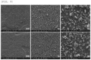
- FIG. 4 is an SEM image of a carbon nanotube dispersion according to Example of the present disclosure.
- pre-processing of the carbon nanotube length was performed at 700 rpm for 10 minutes by mixing zirconia balls (3 mm in diameter) and carbon nanotubes (JEIO, 10B) in an air dry mill (KMtech, KADM-5).
- FIG. 5 is an SEM image of a carbon nanotube dispersion according to Example of the present disclosure.
- pre-processing of the carbon nanotube length was performed at 700 rpm for 15 minutes by mixing zirconia balls (3 mm in diameter) and carbon nanotubes (JEIO, 10B) in an air dry mill (KMtech, KADM-5).
- FIG. 6 is an SEM image of a carbon nanotube dispersion according to Example of the present disclosure.
- pre-processing of the carbon nanotube length was performed at 700 rpm for 20 minutes by mixing zirconia balls (3 mm in diameter) and carbon nanotubes (JEIO, 10B) in an air dry mill (KMtech, KADM-5).
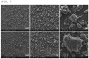
- FIG. 7 is an SEM image of a carbon nanotube dispersion according to Example of the present disclosure.
- pre-processing of the carbon nanotube length was performed at 700 rpm for 25 minutes by mixing zirconia balls (3 mm in diameter) and carbon nanotubes (JEIO, 10B) in an air dry mill (KMtech, KADM-5).
- FIG. 8 is an SEM image of a carbon nanotube dispersion according to Example of the present disclosure.
- pre-processing of the carbon nanotube length was performed at 700 rpm for 30 minutes by mixing zirconia balls (3 mm in diameter) and carbon nanotubes (JEIO, 10B) in an air dry mill (KMtech, KADM-5).
- FIG. 9 is an SEM image of a carbon nanotube dispersion according to Example of the present disclosure.
- a dispersion was prepared according to Comparative Example of the present disclosure without controlling the length by post-processing the carbon nanotube bundle.
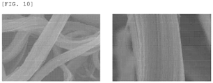
- FIG. 10 is an SEM image of a carbon nanotube dispersion according to Comparative Example of the present disclosure.
- FIG. 11 is a distributed energy-viscosity curve according to the length of carbon nanotubes according to Experimental Example of the present disclosure. Specifically, FIG. 11 is a graph showing changes in viscosity measured in a process of preparing the dispersions of carbon nanotubes post-processed in Comparative Example 1, Example 1, Example 3, and Example 6 through a bead mill process.
- the viscosity change aspect was different from the conventional viscosity change aspect when performing the dispersion process by controlling the length of the carbon nanotubes, and it was confirmed that the saturation point according to the dispersion energy of viscosity increased in proportion to the average length of the carbon nanotubes. In addition, it is considered that it is possible to predict and improve dispersion process efficiency using these properties.
- FIG. 12 is a graph of volume-average particle size distribution and volume-average cumulative particle size distribution according to Experimental Example of the present disclosure. Specifically, a graph that increases and then becomes constant is a volume-based cumulative particle size distribution graph, and a graph that increases and then decreases is a volume-based particle size distribution graph.
- the volume-based cumulative particle size distribution refers to a cumulative curve, and is represented as a percentage of particles smaller than the particles to be considered. For example, if Q3(x)[%] on a left y-axis is 10, it represents the size at 10% of the entire particle size distribution.
- the volume-based particle size distribution refers to a ratio of the volume of particles to be considered to the volume of the particles. Accordingly, all the numbers in dQ3(x)[%] on a right y-axis corresponding to each particle size are added to become 100.
- a green graph on the far right shows a volume-average particle size distribution and volume-average cumulative particle size distribution of a carbon nanotube bundle (average length of carbon nanotubes of 50 ⁇ m or more) of which the length was not controlled through post-processing.
- the remaining graphs show carbon nanotubes of which the length was has been controlled through post-processing, and carbon nanotubes having the average lengths of carbon nanotubes of 50 ⁇ m or less, 40 ⁇ m or less, 30 ⁇ m or less, 25 ⁇ m or less, 20 ⁇ m or less, and 10 ⁇ m or less in order from the right.
- [Table 2] below shows quantifying the particle sizes of Dv(10), Dv(50), and Dv(90) in FIG. 11 .
- Dv(x) 50 ⁇ m or more 50 ⁇ m or less 40 ⁇ m or less 30 ⁇ m or less 25 ⁇ m or less 20 ⁇ m or less 10 ⁇ m or less 10 15.7 9.2 7.3 5.4 4.3 3.4 2.1 50 57.1 25.7 18.6 13.5 10.4 8 4.3 90 117.2 45.4 35.4 27.9 22.3 15.5 8
Landscapes
- Chemical & Material Sciences (AREA)
- Engineering & Computer Science (AREA)
- Materials Engineering (AREA)
- Organic Chemistry (AREA)
- Nanotechnology (AREA)
- Inorganic Chemistry (AREA)
- Life Sciences & Earth Sciences (AREA)
- Wood Science & Technology (AREA)
- Power Engineering (AREA)
- Chemical Kinetics & Catalysis (AREA)
- Microelectronics & Electronic Packaging (AREA)
- Crystallography & Structural Chemistry (AREA)
- Manufacturing & Machinery (AREA)
- General Chemical & Material Sciences (AREA)
- Electrochemistry (AREA)
- Carbon And Carbon Compounds (AREA)
- Catalysts (AREA)
Abstract
Description
- The present disclosure relates to a method for preparing a carbon nanotube dispersion.
- Carbon nanotubes may have excellent mechanical robustness and chemical stability, have both semiconductor and conductor properties, and have small diameters, large lengths, and hollow properties, and thus are suitable as materials for flat panel displays, transistors, energy storage media, etc. and have high potential for application as various nano-sized electronic devices.
- In order to use carbon nanotubes for forming conductive films or manufacturing various other electronic devices, the carbon nanotubes need to be effectively dispersed in a matrix such as a solvent or binder. However, the carbon nanotubes have a strong tendency to aggregate into bundles within the matrix due to strong Van der Waals forces and thus have a disadvantage of making processing difficult due to very low solubility in water or other solvents.
- When the carbon nanotubes aggregate within the matrix, there may be problems that the unique properties of the carbon nanotubes may not be exhibited, or the uniformity of thin film properties deteriorates when manufactured as a thin film. In particular, the dispersion of carbon nanotubes is more important in display applications where transparency needs to be secured, like the case of using a transistor as a semiconductor material or an electrode as a conductor material. However, when the dispersibility is poor, carbon nanotube strands are not completely separated but aggregate in bundles, so that the desired transmittance cannot be secured even if the same performance is achieved.
- However, carbon nanotubes used in a conventional method of preparing a carbon nanotube dispersion tend to rapidly increase and then decrease in viscosity of the dispersion as the dispersion energy increases, and such an irregular change in viscosity increases variables in the preparing process of the carbon nanotube dispersion to cause problems in efficiently preparing the dispersion.
- Accordingly, if the tendency of the viscosity can be predicted during the preparing process of the carbon nanotube dispersion, process efficiency may be increased.
-
Korean Patent Registration No. 10-1807798 Korean Patent Registration No. 10-1807798 - An object to be achieved by the present disclosure is to provide a method for preparing a carbon nanotube dispersion having a predictable viscosity tendency during a dispersion process by controlling an average length of carbon nanotubes.
- Another object to be achieved by the present disclosure is to provide a carbon nanotube dispersion prepared by the preparing method.
- Yet another object to be achieved by the present disclosure is to provide an energy storage device including the carbon nanotube dispersion.
- Yet another object to be achieved by the present disclosure is to provide a composite material including the carbon nanotube dispersion.
- Yet another object to be achieved by the present disclosure is to provide a pigment including the carbon nanotube dispersion.
- Yet another object to be achieved by the present disclosure is to provide a paint including the carbon nanotube dispersion.
- However, the technical challenges sought to be achieved by the embodiments of the present application are not limited to the technical challenges described above, and other technical challenges may exist.
- According to a first aspect of the present disclosure, there is provided a method for preparing a carbon nanotube dispersion including preparing a carbon nanotube bundle; post-processing the carbon nanotube bundle to reduce an average length of the carbon nanotube bundle to 50 µm or less; and dispersing the post-processed carbon nanotube bundle in a solution.
- According to an exemplary embodiment of the present disclosure, a volume-average (cumulative) diameter Dv(90) of the post-processed carbon nanotube bundle may be 50 µm, but is not limited thereto.
- According to an exemplary embodiment of the present disclosure, the solution may include a solvent and a dispersant, but is not limited thereto.
- According to an exemplary embodiment of the present disclosure, the solvent may be selected from the group consisting of deionized water, N-methyl-2-pyrrolidone, N,N-dimethylformamide, N,N-dimethylacetamide, dimethyl sulfoxide, ethanol, methanol, pentyl alcohol, acetone, methyl ethyl ketone, cyclopentanone, ethyl acetate, ethylene glycol, diethylene glycol, 1-propanol, isopropanol, 1-butanol, isobutanol, octanol, ethylene glycol monoethyl ether, diethylene glycol monoethyl ether, triethylene glycol monoethyl ether, tetraethylene glycol monoethyl ether, and combinations thereof, but is not limited thereto.
- According to an exemplary embodiment of the present disclosure, the dispersant may be selected from the group consisting of polyvinylpyrrolidone, hydrogenated nitrile rubber, polyvinyl alcohol, polyvinyl methyl ether, polyethylene glycol, polypropylene glycol, polyacrylamide, polyethylene oxide, polyethylene oxide/propylene oxide block copolymer, polyacrylic acid salts, cellulose derivatives, starch derivatives, and combinations thereof, but is not limited thereto.
- According to an exemplary embodiment of the present disclosure, the carbon nanotubes may be prepared by chemical vapor deposition in the presence of a catalyst, but are not limited thereto.
- According to an exemplary embodiment of the present disclosure, the carbon nanotubes may be prepared using a reaction source selected from the group consisting of acetylene, ethylene, methane, and combinations thereof, but are not limited thereto.
- According to an exemplary embodiment of the present disclosure, the catalyst may include a catalyst selected from the group consisting of Fe, Co, Ni, Al, Mg, Mo, Si, and combinations thereof, but is not limited thereto.
- According to an exemplary embodiment of the present disclosure, the catalyst may be prepared by a method selected from the group consisting of a combusting method, a supporting method, a probing method, a sol-gel method, and combinations thereof, but is not limited thereto.
- According to an exemplary embodiment of the present disclosure, the dispersing step may be performed by a process selected from the group consisting of an ultrasonic process, a pulverization process by physical impact force, a pulverization process by physical shear force, a high pressure process, a supercritical/subcritical process, and combinations thereof, but is not limited thereto.
- According to an exemplary embodiment of the present disclosure, the post-processing may include dry post-processing and/or wet post-processing, but is not limited thereto.
- According to an exemplary embodiment of the present disclosure, the dry post-processing may be selected from the group consisting of air dry mill, bead mill, attrition mill, jet mill, steam jet mill, and combinations thereof, but is not limited thereto.
- According to an exemplary embodiment of the present disclosure, the wet post-processing may be selected from the group consisting of bead mill, attrition mill, sonication, shear mill, high pressure homogenizer, mechanical homogenizer and combinations thereof, but is not limited thereto.
- According to an exemplary embodiment of the present disclosure, the post-processed carbon nanotubes may have a specific surface area of 50 cm2/g or more and a diameter of 1 nm or more, but are not limited thereto.
- According to a second aspect of the present disclosure, there is provided a carbon nanotube dispersion prepared by the method according to the first aspect of the present disclosure, in which a saturation point according to the dispersion energy of a viscosity (µ) of the carbon nanotube dispersion is proportional to an average length value of the post-processed carbon nanotubes.
- According to a third aspect of the present disclosure, there is provided an energy storage device including the carbon nanotube dispersion according to the second aspect of the present disclosure.
- According to a fourth aspect of the present disclosure, there is provided a composite material including the carbon nanotube dispersion according to the second aspect of the present disclosure.
- According to a fifth aspect of the present disclosure, there is provided a pigment including the carbon nanotube dispersion according to the second aspect of the present disclosure.
- According to a sixth aspect of the present disclosure, there is provided a paint including the carbon nanotube dispersion according to the second aspect of the present disclosure.
- The above-mentioned technical solutions are merely exemplary and should not be construed as limiting the present disclosure. In addition to the above-described exemplary examples, additional examples may exist in the drawings and detailed description of the invention.
- In a conventional method of preparing a carbon nanotube dispersion, the viscosity of the dispersion tended to be changed irregularly as dispersion energy was applied. Such an irregular change in viscosity has a problem of reducing process efficiency when preparing the dispersion.
- However, in the method for preparing the carbon nanotube dispersion according to the present disclosure, it is possible to predict and improve efficiency of the carbon nanotube dispersion process using material properties according to the length of the carbon nanotubes, and input dispersion energy and viscosity properties according to the length of the carbon nanotubes.
- Specifically, the dispersion is prepared by controlling the length of the carbon nanotube bundle to 50 µm or less to have a different aspect from the viscosity tendency of the conventional carbon nanotube dispersion, and to predict and improve process efficiency during the dispersion process using the viscosity tendency.
- Specifically, as a result, the saturation point according to the dispersion energy of the viscosity (µ) of the carbon nanotube dispersion according to the present disclosure is proportional to the average length of the carbon nanotubes.
- However, effects obtainable herein are not limited to the effects described above, and other effects may be present.
-
-
FIG. 1 is a flowchart of a method for preparing a carbon nanotube dispersion according to an exemplary embodiment of the present disclosure; -
FIG. 2 is a distributed energy-viscosity curve according to the length of carbon nanotubes according to an exemplary embodiment of the present disclosure; -
FIG. 3 is a graph showing a viscosity index of the dispersion according to the length of carbon nanotubes according to an exemplary embodiment of the present disclosure; -
FIG. 4 is an SEM image of a carbon nanotube dispersion according to Example of the present disclosure; -
FIG. 5 is an SEM image of a carbon nanotube dispersion according to Example of the present disclosure; -
FIG. 6 is an SEM image of a carbon nanotube dispersion according to Example of the present disclosure; -
FIG. 7 is an SEM image of a carbon nanotube dispersion according to Example of the present disclosure; -
FIG. 8 is an SEM image of a carbon nanotube dispersion according to Example of the present disclosure; -
FIG. 9 is an SEM image of a carbon nanotube dispersion according to Example of the present disclosure; -
FIG. 10 is an SEM image of a carbon nanotube dispersion according to Comparative Example of the present disclosure; -
FIG. 11 is a distributed energy-viscosity curve according to the length of carbon nanotubes according to Experimental Example of the present disclosure; and -
FIG. 12 is a graph of volume-average particle size distribution and volume-average cumulative particle size distribution according to Experimental Example of the present disclosure. - Hereinafter, Examples of the present disclosure will be described in detail so as to be easily implemented by those skilled in the art, with reference to the accompanying drawings.
- However, the present disclosure may be embodied in many different forms and are not limited to the examples to be described herein. In addition, parts not related with the description have been omitted in order to clearly describe the present disclosure in the drawings and throughout the present specification, like reference numerals designate like elements.
- Throughout this specification, when a certain part is "connected" with the other part, it is meant that the certain part may be "directly connected" with the other part and "electrically connected" with the other part with another element interposed therebetween.
- Throughout the present specification, it will be understood that when a certain member is located "on", "above", "at the top of", "under", "below", and "at the bottom of" the other member, a certain member is in contact with the other member and another member may also be present between the two members.
- Throughout this specification, unless explicitly described to the contrary, when a certain part "includes" a certain component, it will be understood to further include another component without excluding another component.
- The terms "about", "substantially", and the like to be used in the present specification are used as a numerical value or a value close to the numerical value when inherent manufacturing and material tolerances are presented in the stated meaning, and used to prevent an unscrupulous infringer from unfairly using disclosed contents in which precise or absolute numerical values are mentioned to help in the understanding of the present disclosure. Throughout this specification, the term of "step to" or "step of" does not mean "step for".
- Throughout the present specification, the term "combinations thereof" included in the expression of the Markush form means one or more mixtures or combinations selected from the group consisting of components described in the expression of the Markush form, and means to include at least one selected from the group consisting of the components.
- Throughout the present specification, "A and/or B" means "A or B, or A and B".
- Hereinafter, a method for preparing a carbon nanotube dispersion according to the present disclosure will be described in detail with reference to exemplary embodiments, Examples, and drawings. However, the present disclosure is not limited to these exemplary embodiments, Examples and drawings.
- According to a first aspect of the present disclosure, there is provided a method for preparing a carbon nanotube dispersion including preparing a carbon nanotube bundle; post-processing the carbon nanotube bundle to reduce an average length of the carbon nanotube bundle to 50 µm or less; and dispersing the post-processed carbon nanotube bundle in a solution.
- In a conventional method of preparing a carbon nanotube dispersion, the viscosity of the dispersion tended to be changed irregularly as dispersion energy was applied. Such an irregular change in viscosity has a problem of reducing process efficiency when preparing the dispersion.
- However, in the method for preparing the carbon nanotube dispersion according to the present disclosure, it is possible to predict and improve efficiency of the carbon nanotube dispersion process using material properties according to the length of the carbon nanotubes, and input dispersion energy and viscosity properties according to the length of the carbon nanotubes.
- Specifically, in the present disclosure, by preparing the dispersion by controlling the length of the carbon nanotube bundle to 50 µm or less, unlike the viscosity tendency of the conventional carbon nanotube dispersion, as dispersion energy is applied, there is a point where the viscosity is increased and then saturated, and a saturation point according to the dispersion energy of the viscosity (µ) of the carbon nanotube dispersion tends to be proportional to the average length value of the carbon nanotubes. It is possible to predict and improve process efficiency during the dispersing process using such viscosity tendency.
- Hereinafter, a method for preparing a carbon nanotube dispersion of the present disclosure will be described with reference to
FIG. 1 . -
FIG. 1 is a flowchart of a method for preparing a carbon nanotube dispersion according to an exemplary embodiment of the present disclosure. - First, the carbon nanotube bundle is prepared (S100).
- According to an exemplary embodiment of the present disclosure, the carbon nanotubes may be prepared by chemical vapor deposition in the presence of a catalyst, but are not limited thereto.
- According to an exemplary embodiment of the present disclosure, the carbon nanotubes may be prepared using a reaction source selected from the group consisting of acetylene, ethylene, methane, and combinations thereof, but are not limited thereto.
- According to an exemplary embodiment of the present disclosure, the catalyst may include a catalyst selected from the group consisting of Fe, Co, Ni, Al, Mg, Mo, Si, and combinations thereof, but is not limited thereto.
- According to an exemplary embodiment of the present disclosure, the catalyst may be prepared by a method selected from the group consisting of a combusting method, a supporting method, a probing method, a sol-gel method, and combinations thereof, but is not limited thereto.
- Although described below, the average length of the carbon nanotube bundle may be controlled by performing dry post-processing and/or wet post-processing.
- When performing the dry post-processing, the length of the carbon nanotubes is controlled by directly using the prepared carbon nanotube bundle, and then a carbon nanotube dispersion may be prepared.
- When performing the wet post-processing, the length of the carbon nanotubes is controlled using a solution in which the carbon nanotube bundle is added to a solvent (water, ethanol, etc.), the solution is dried to be prepared in a powder state, and then the carbon nanotube dispersion may be prepared.
- Accordingly, in the preparing of the carbon nanotube bundle, the carbon nanotube bundle may be prepared in a solid phase (carbon nanotube bundle) or a liquid phase (solution containing the carbon nanotube bundle) depending on how post-processing is performed.
- Next, the carbon nanotube bundle is post-processed to reduce the average length of the carbon nanotube bundle to 50 µm or less (S200).
- According to an exemplary embodiment of the present disclosure, a volume-average (cumulative) diameter Dv(90) of the post-processed carbon nanotube bundle may be 50 µm, but is not limited thereto.
- The volume-average (cumulative) diameter is considered as a sphere having the same volume because the sizes of non-spherical particles may not be expressed as one value, and Dv(10) refers to a size at 10% of the entire particle size distribution, Dv(50) refers to a size at 500 of the entire particle size distribution (median value), and Dv(90) refers to a size at 90% of the entire particle size distribution.
- Accordingly, the volume-average (cumulative) diameter Dv(90) of 50 µm means that 90% of the particle sizes are 50 µm or less, which is able to be interpreted as the majority of the particle sizes are 50 µm or less.
- According to an exemplary embodiment of the present disclosure, the post-processed carbon nanotubes may have a specific surface area of 50 cm2/g or more and a diameter of 1 nm or more, but are not limited thereto.
- According to an exemplary embodiment of the present disclosure, the post-processing may include dry post-processing and/or wet post-processing, but is not limited thereto.
- As described above, when performing the dry post-processing, the post-processing is performed by directly using the prepared carbon nanotube bundle, and the carbon nanotube dispersion may be prepared using the post-processed carbon nanotubes.
- On the other hand, when performing the wet post-processing, the post-processing may be performed using a solution in which the carbon nanotube bundle is added to a solvent (water, ethanol, etc.), and the carbon nanotubes in which the length is controlled through the wet post-processing are dried to be prepared in a powder state, and then used for the preparation of the carbon nanotube dispersion.
- According to an exemplary embodiment of the present disclosure, the dry post-processing may be selected from the group consisting of an air dry mill, a bead mill, an attrition mill, a jet mill, a steam jet mill, and combinations thereof, but is not limited thereto.
- According to an exemplary embodiment of the present disclosure, the wet post-processing may be selected from the group consisting of bead mill, attrition mill, sonication, shear mill, high pressure homogenizer, mechanical homogenizer and combinations thereof, but is not limited thereto.
- Finally, the post-processed carbon nanotube bundle is dispersed in the solution (S300).
- According to an exemplary embodiment of the present disclosure, the step of dispersing the post-processed carbon nanotube bundle in the solution may be further included, but is not limited thereto.
- According to an exemplary embodiment of the present disclosure, the solution may include a solvent and a dispersant, but is not limited thereto.
- According to an exemplary embodiment of the present disclosure, the solvent may be selected from the group consisting of deionized water, N-methyl-2-pyrrolidone, N,N-dimethylformamide, N,N-dimethylacetamide, dimethyl sulfoxide, ethanol, methanol, pentyl alcohol, acetone, methyl ethyl ketone, cyclopentanone, ethyl acetate, ethylene glycol, diethylene glycol, 1-propanol, isopropanol, 1-butanol, isobutanol, octanol, ethylene glycol monoethyl ether, diethylene glycol monoethyl ether, triethylene glycol monoethyl ether, tetraethylene glycol monoethyl ether, and combinations thereof, but is not limited thereto.
- According to an exemplary embodiment of the present disclosure, the dispersant may be selected from the group consisting of polyvinylpyrrolidone, hydrogenated nitrile rubber, polyvinyl alcohol, polyvinyl methyl ether, polyethylene glycol, polypropylene glycol, polyacrylamide, polyethylene oxide, polyethylene oxide/propylene oxide block copolymer, polyacrylic acid salts, cellulose derivatives, starch derivatives, and combinations thereof, but is not limited thereto.
- According to an exemplary embodiment of the present disclosure, the dispersing step may be performed by a process selected from the group consisting of an ultrasonic process, a pulverization process by physical impact force, a pulverization process by physical shear force, a high pressure process, a supercritical/subcritical process, and combinations thereof, but is not limited thereto.
- In addition, according to a second aspect of the present disclosure, there is provided a carbon nanotube dispersion prepared by the method according to the first aspect of the present disclosure, in which a saturation point according to the dispersion energy of a viscosity (µ) of the carbon nanotube dispersion is proportional to an average length value of the post-processed carbon nanotubes.
- With respect to the carbon nanotube dispersion according to the second aspect of the present disclosure, the detailed description of duplicated parts with the first aspect of the present disclosure has been omitted, but even if the description thereof has been omitted, the contents described in the first aspect of the present disclosure may be equally applied to the second aspect of the present disclosure.
- The carbon nanotubes according to the present disclosure have an average length of 50 µm or less, and accordingly, have a different aspect from the tendency of the viscosity change of conventional carbon nanotubes. As the conventional carbon nanotube dispersion increases the dispersion energy, the viscosity has been irregularly changed, but in the carbon nanotube dispersion according to the present disclosure, as the dispersion energy increases, there is a saturation point where the viscosity increases and then becomes constant, and the saturation point decreases as the average length of the carbon nanotubes decreases.
-
FIG. 2 is a distributed energy-viscosity curve according to the length of carbon nanotubes according to an exemplary embodiment of the present disclosure. - Referring to
FIG. 2 , it may be confirmed that when the average length of the carbon nanotubes is 50 µm or more, as the dispersion energy increases, the viscosity increases rapidly and then tends to decrease. This irregular change in viscosity increases the process variables during the preparing process of the dispersion, and thus there is a limit to operating an efficient process. - On the other hand, when the average length of the carbon nanotubes is 50 µm or less, it may be confirmed that there is a saturation point where the viscosity increases and then becomes constant as the dispersion energy increases. The saturation point decreases as the average length of carbon nanotubes decreases. Accordingly, a relationship between the average length of carbon nanotubes and the viscosity of the dispersion is represented by a viscosity index of the dispersion according to the length of the carbon nanotubes, thereby predicting and improving the efficiency of the process when preparing the dispersion.
-
FIG. 3 is a graph showing a viscosity index of the dispersion according to the length of carbon nanotubes according to an exemplary embodiment of the present disclosure. - Hereinafter, the viscosity index of the dispersion according to the length of the carbon nanotube is defined with reference to
FIG. 3 . - The viscosity may be represented as a value obtained by dividing shear stress by a shear rate. The shear stress is an expression of a cross-sectional area A (cm2), which is a part where each fluid layer is in contact with each other when each fluid layer was considered three-dimensional. Specifically, when a constant force F (dynes) is applied to the upper part of the fluid layer, a constant force F (dynes) is generated at the contact surface of each fluid layer, that is, the cross-sectional area A (cm2). At this time, the force received per cross-sectional area of the fluid layer is the shear stress. In other words, a value obtained by dividing a friction force F (dynes) by a unit area A (cm2) is the shear stress F/A (dynes/cm2).
- A stationary phase and a mobile phase exist at a predetermined distance X (cm), and a fluid also exists between the phases. When the upper plate, that is, the mobile phase is moved from the outside with a constant force, the fluid also moves at a constant velocity V (cm/sec). The farther the fluid is from the mobile phase, the slower the velocity is, and the velocity distribution of the fluid flow is linear. The shear rate V/X (sec-1) is a value obtained by dividing a fluid velocity V (cm/sec) between the two plates by a distance X (cm) between the two plates.
- The viscosity is a value obtained by dividing the shear stress (dynes/cm2) by the shear rate (sec-1), and ultimately, the viscosity may be represented as [Equation 1] below.

(wherein, - M represents a factor caused by a force;
- L represents a distance between the mobile phase fluid and the stationary phase fluid; and
- T represents a measurement time).
- Referring to
FIG. 3 , as defined in [Equation 1], the viscosity may represent µ1 = M1/ (L1·T1) (g/cm·s) and µ2 = M2/ (L2·T2) (g/cm·s) (µ1 is the viscosity of a dispersion with an average length of carbon nanotubes of 50 µm, and µ2 is the viscosity of a dispersion with an average length of carbon nanotubes of 30 µm), and because L and T are fixed constant values, a viscosity change Δµ may be expressed as follows.
- From experimental data, it may be seen that µ1 is always larger than µ2.
- That is, since µ1 > µ2, and L and T are constants, it may be seen that M1 > M2 and the average length of M and the carbon nanotubes are proportional to each other, and in other words, M = αLCNT.
- Accordingly, the viscosity change Δµ may be represented as Δµ = αΔLCNT/ (L·T) = λΔLCNT, wherein λ is a dispersion viscosity index according to the length of the carbon nanotube. By using this, it is possible to predict the viscosity according to the length of the carbon nanotube and to improve the efficiency of the process.
- Referring to
FIG. 3 , it may be seen that it is possible to predict the viscosity at the same time when the dispersion is performed in the same process. For example, when T1 is 5 hours, if LCNT1 = 50 µm and µ1 = 2000 cp, and LCNT2 = 10 µm and µ2 = 200 cp, it may be seen that a viscosity change Δµ = [ (2000-200) / (50-10) ] LCNT = 45 LCNT, and if the average length of the carbon nanotubes is 20 µm, it is expectable that the viscosity after 5 hours is 900 cp. - In addition, according to a third aspect of the present disclosure, there is provided an energy storage device including the carbon nanotube dispersion according to the second aspect of the present disclosure.
- With respect to the energy storage device according to the third aspect of the present disclosure, the detailed description of parts duplicated with the second aspect of the present disclosure has been omitted, but even if the description has been omitted, the contents disclosed in the second aspect of the present disclosure may be equally applied to the third aspect of the present disclosure.
- In addition, according to a fourth aspect of the present disclosure, there is provided a composite material including the carbon nanotube dispersion according to the second aspect of the present disclosure.
- With respect to the composite material according to the fourth aspect of the present disclosure, the detailed description of parts duplicated with the second aspect of the present disclosure has been omitted, but even if the description has been omitted, the contents disclosed in the second aspect of the present disclosure may be equally applied to the fourth aspect of the present disclosure.
- In addition, according to a fifth aspect of the present disclosure, there is provided a pigment including the carbon nanotube dispersion according to the second aspect of the present disclosure.
- With respect to the pigment according to the fifth aspect of the present disclosure, the detailed description of parts duplicated with the second aspect of the present disclosure has been omitted, but even if the description has been omitted, the contents disclosed in the second aspect of the present disclosure may be equally applied to the fifth aspect of the present disclosure.
- In addition, according to a sixth aspect of the present disclosure, there is provided a paint including the carbon nanotube dispersion according to the second aspect of the present disclosure.
- With respect to the paint according to the sixth aspect of the present disclosure, the detailed description of parts duplicated with the second aspect of the present disclosure has been omitted, but even if the description has been omitted, the contents disclosed in the second aspect of the present disclosure may be equally applied to the sixth aspect of the present disclosure.
- Hereinafter, the present disclosure will be described in more detail with reference to the following Examples, but the following Examples are only for illustrative purposes and are not intended to limit the scope of the present disclosure.
- First, pre-processing of the carbon nanotube length was performed at 700 rpm for 5 minutes by mixing zirconia balls (3 mm in diameter) and carbon nanotubes (JEIO, 10B) in an air dry mill (KMtech, KADM-5).
- Next, 1 wt% of carbon nanotubes (average length of 50 µm) and 0.5 wt% of polyvinylpyrrolidone (PVP) were mixed with 98.5 wt% of a NMP solvent, and a carbon nanotube dispersion was prepared in a bead mill (WAB, DYNO-MILL ECM-AP) at a zirconia ball (1 mm in diameter) filling rate of 30% and a velocity of 1000 rpm.
-
FIG. 4 is an SEM image of a carbon nanotube dispersion according to Example of the present disclosure. - First, pre-processing of the carbon nanotube length was performed at 700 rpm for 10 minutes by mixing zirconia balls (3 mm in diameter) and carbon nanotubes (JEIO, 10B) in an air dry mill (KMtech, KADM-5).
- Next, 1 wt% of carbon nanotubes (average length of 40 µm) and 0.5 wt% of polyvinylpyrrolidone (PVP) were mixed with 98.5 wt% of a NMP solvent, and a carbon nanotube dispersion was prepared in a bead mill (WAB, DYNO-MILL ECM-AP) at a zirconia ball (1 mm in diameter) filling rate of 30% and a velocity of 1000 rpm.
-
FIG. 5 is an SEM image of a carbon nanotube dispersion according to Example of the present disclosure. - First, pre-processing of the carbon nanotube length was performed at 700 rpm for 15 minutes by mixing zirconia balls (3 mm in diameter) and carbon nanotubes (JEIO, 10B) in an air dry mill (KMtech, KADM-5).
- Next, 1 wt% of carbon nanotubes (average length of 30 µm) and 0.5 wt% of polyvinylpyrrolidone (PVP) were mixed with 98.5 wt% of a NMP solvent, and a carbon nanotube dispersion was prepared in a bead mill (WAB, DYNO-MILL ECM-AP) at a zirconia ball (1 mm in diameter) filling rate of 30% and a velocity of 1000 rpm.
-
FIG. 6 is an SEM image of a carbon nanotube dispersion according to Example of the present disclosure. - First, pre-processing of the carbon nanotube length was performed at 700 rpm for 20 minutes by mixing zirconia balls (3 mm in diameter) and carbon nanotubes (JEIO, 10B) in an air dry mill (KMtech, KADM-5).
- Next, 1 wt% of carbon nanotubes (average length of 25 µm) and 0.5 wt% of polyvinylpyrrolidone (PVP) were mixed with 98.5 wt% of a NMP solvent, and a carbon nanotube dispersion was prepared in a bead mill (WAB, DYNO-MILL ECM-AP) at a zirconia ball (1 mm in diameter) filling rate of 30% and a velocity of 1000 rpm.
-
FIG. 7 is an SEM image of a carbon nanotube dispersion according to Example of the present disclosure. - First, pre-processing of the carbon nanotube length was performed at 700 rpm for 25 minutes by mixing zirconia balls (3 mm in diameter) and carbon nanotubes (JEIO, 10B) in an air dry mill (KMtech, KADM-5).
- Next, 1 wt% of carbon nanotubes (average length of 20 µm) and 0.5 wt% of polyvinylpyrrolidone (PVP) were mixed with 98.5 wt% of a NMP solvent, and a carbon nanotube dispersion was prepared in a bead mill (WAB, DYNO-MILL ECM-AP) at a zirconia ball (1 mm in diameter) filling rate of 30% and a velocity of 1000 rpm.
-
FIG. 8 is an SEM image of a carbon nanotube dispersion according to Example of the present disclosure. - First, pre-processing of the carbon nanotube length was performed at 700 rpm for 30 minutes by mixing zirconia balls (3 mm in diameter) and carbon nanotubes (JEIO, 10B) in an air dry mill (KMtech, KADM-5).
- Next, 1 wt% of carbon nanotubes (average length of 10 µm) and 0.5 wt% of polyvinylpyrrolidone (PVP) were mixed with 98.5 wt% of a NMP solvent, and a carbon nanotube dispersion was prepared in a bead mill (WAB, DYNO-MILL ECM-AP) at a zirconia ball (1 mm in diameter) filling rate of 30% and a velocity of 1000 rpm.
-
FIG. 9 is an SEM image of a carbon nanotube dispersion according to Example of the present disclosure. - A dispersion was prepared according to Comparative Example of the present disclosure without controlling the length by post-processing the carbon nanotube bundle.
- 1 wt% of carbon nanotubes (average length of 50 µm or more) and 0.5 wt% of polyvinylpyrrolidone (PVP) were mixed with 98.5 wt% of a NMP solvent, and a carbon nanotube dispersion was prepared in a bead mill (WAB, DYNO-MILL ECM-AP) at a zirconia ball (1 mm in diameter) filling rate of 30% and a velocity of 1000 rpm.
-
FIG. 10 is an SEM image of a carbon nanotube dispersion according to Comparative Example of the present disclosure. -
FIG. 11 is a distributed energy-viscosity curve according to the length of carbon nanotubes according to Experimental Example of the present disclosure. Specifically,FIG. 11 is a graph showing changes in viscosity measured in a process of preparing the dispersions of carbon nanotubes post-processed in Comparative Example 1, Example 1, Example 3, and Example 6 through a bead mill process. - Referring to
FIG. 11 , it may be seen that the carbon nanotubes (raw material) of Comparative Example 1, of which the length was not controlled through post-processing, show irregular viscosity changes in which the viscosity increased and then decreased as dispersion energy was applied. - On the other hand, it may be seen that in the carbon nanotubes of Examples 1 (50 µm or less), 3 (30 µm or less), and 6 (10 µm or less) of which the length was controlled through post-processing, a section in which the viscosity gradually increased and then became constant occurred.
- [Table 1] below is a table showing actually measured viscosity values of Experimental Example 1.
[Table 1] Pass number (Bead mill Process, Requiring 30 minutes per pass) viscosity (cp) Raw material 50 µm or less 30 µm or less 10 µm or less 10 2809 83 13 5 20 3489 365.9 186 30 30 3880 500 277 116 40 2880 623.9 332.9 158 50 2430 553 425.9 214 60 1890 640.9 557.8 255.9 70 1429 691.9 535.9 317.9 80 1300 808.8 579.9 335.9 90 1229 733.8 679.9 329.9 100 1099 783.8 611.9 333.9 - Through this, it was confirmed that the viscosity change aspect was different from the conventional viscosity change aspect when performing the dispersion process by controlling the length of the carbon nanotubes, and it was confirmed that the saturation point according to the dispersion energy of viscosity increased in proportion to the average length of the carbon nanotubes. In addition, it is considered that it is possible to predict and improve dispersion process efficiency using these properties.
-
FIG. 12 is a graph of volume-average particle size distribution and volume-average cumulative particle size distribution according to Experimental Example of the present disclosure. Specifically, a graph that increases and then becomes constant is a volume-based cumulative particle size distribution graph, and a graph that increases and then decreases is a volume-based particle size distribution graph. - The volume-based cumulative particle size distribution refers to a cumulative curve, and is represented as a percentage of particles smaller than the particles to be considered. For example, if Q3(x)[%] on a left y-axis is 10, it represents the size at 10% of the entire particle size distribution.
- The volume-based particle size distribution refers to a ratio of the volume of particles to be considered to the volume of the particles. Accordingly, all the numbers in dQ3(x)[%] on a right y-axis corresponding to each particle size are added to become 100.
- Referring to
FIG. 12 , it may be visually confirmed that the particle size decreases as the post-processing time increases. Specifically, a green graph on the far right shows a volume-average particle size distribution and volume-average cumulative particle size distribution of a carbon nanotube bundle (average length of carbon nanotubes of 50 µm or more) of which the length was not controlled through post-processing. The remaining graphs show carbon nanotubes of which the length was has been controlled through post-processing, and carbon nanotubes having the average lengths of carbon nanotubes of 50 µm or less, 40 µm or less, 30 µm or less, 25 µm or less, 20 µm or less, and 10 µm or less in order from the right. - [Table 2] below shows quantifying the particle sizes of Dv(10), Dv(50), and Dv(90) in
FIG. 11 .[Table 2] Dv(x) 50 µm or more 50 µm or less 40 µm or less 30 µm or less 25 µm or less 20 µm or less 10 µm or less 10 15.7 9.2 7.3 5.4 4.3 3.4 2.1 50 57.1 25.7 18.6 13.5 10.4 8 4.3 90 117.2 45.4 35.4 27.9 22.3 15.5 8 - Referring to [Table 2], it was confirmed that as the post-processing time increased, the length of the carbon nanotube was controlled to become smaller, and thus the value of Dv90 decreased, and it was confirmed that through the particle size of Dv(90), which referred to the size at 90% of the entire particle size distribution, the majority of particles were 50 µm or more, 50 µm or less, 40 µm or less, 30 µm or less, 25 µm or less, 20 µm or less, and 10 µm or less.
- The aforementioned description of the present disclosure is to be exemplified, and it will be understood by those skilled in the art that the present disclosure may be easily modified in other detailed forms without changing the technical spirit or required features of the present disclosure. Therefore, it should be appreciated that the examples described above are illustrative in all aspects and are not restricted. Therefore, it should be appreciated that the exemplary embodiments described above are illustrative in all aspects and are not restricted.
- The scope of the present disclosure is represented by appended claims to be described below rather than the detailed description, and it is to be interpreted that the meaning and scope of the claims and all the changes or modified forms derived from the equivalents thereof come within the scope of the present disclosure.
Claims (19)
- A method for preparing a carbon nanotube dispersion comprising:preparing a carbon nanotube bundle;post-processing the carbon nanotube bundle to reduce an average length of the carbon nanotube bundle to 50 µm or less; anddispersing the post-processed carbon nanotube bundle in a solution.
- The method for preparing the carbon nanotube dispersion of claim 1, wherein a volume-average (cumulative) diameter Dv(90) of the post-processed carbon nanotube bundle is 50 µm.
- The method for preparing the carbon nanotube dispersion of claim 1, wherein the solution includes a solvent and a dispersant.
- The method for preparing the carbon nanotube dispersion of claim 3, wherein the solvent is selected from the group consisting of deionized water, N-methyl-2-pyrrolidone, N,N-dimethylformamide, N,N-dimethylacetamide, dimethyl sulfoxide, ethanol, methanol, pentyl alcohol, acetone, methyl ethyl ketone, cyclopentanone, ethyl acetate, ethylene glycol, diethylene glycol, 1-propanol, isopropanol, 1-butanol, isobutanol, octanol, ethylene glycol monoethyl ether, diethylene glycol monoethyl ether, triethylene glycol monoethyl ether, tetraethylene glycol monoethyl ether, and combinations thereof.
- The method for preparing the carbon nanotube dispersion of claim 3, wherein the dispersant is selected from the group consisting of polyvinylpyrrolidone, hydrogenated nitrile rubber, polyvinyl alcohol, polyvinyl methyl ether, polyethylene glycol, polypropylene glycol, polyacrylamide, polyethylene oxide, polyethylene oxide/propylene oxide block copolymer, polyacrylic acid salts, cellulose derivatives, starch derivatives, and combinations thereof.
- The method for preparing the carbon nanotube dispersion of claim 1, wherein the carbon nanotubes are prepared by chemical vapor deposition in the presence of a catalyst.
- The method for preparing the carbon nanotube dispersion of claim 1, wherein the carbon nanotubes are prepared using a reaction source selected from the group consisting of acetylene, ethylene, methane, and combinations thereof.
- The method for preparing the carbon nanotube dispersion of claim 6, wherein the catalyst includes a catalyst selected from the group consisting of Fe, Co, Ni, Al, Mg, Mo, Si, and combinations thereof.
- The method for preparing the carbon nanotube dispersion of claim 6, wherein the catalyst is prepared by a method selected from the group consisting of a combusting method, a supporting method, a probing method, a sol-gel method, and combinations thereof.
- The method for preparing the carbon nanotube dispersion of claim 1, wherein the dispersing step is performed by a process selected from the group consisting of an ultrasonic process, a pulverization process by physical impact force, a pulverization process by physical shear force, a high pressure process, a supercritical/subcritical process, and combinations thereof.
- The method for preparing the carbon nanotube dispersion of claim 1, wherein the post-processing includes dry post-processing and/or wet post-processing.
- The method for preparing the carbon nanotube dispersion of claim 11, wherein the dry post-processing is selected from the group consisting of an air dry mill, a bead mill, an attrition mill, a jet mill, a steam jet mill, and combinations thereof.
- The method for preparing the carbon nanotube dispersion of claim 11, wherein the wet post-processing is selected from the group consisting of bead mill, attrition mill, sonication, shear mill, high pressure homogenizer, mechanical homogenizer and combinations thereof.
- The method for preparing the carbon nanotube dispersion of claim 1, wherein the post-processed carbon nanotubes have a specific surface area of 50 cm2/g or more and a diameter of 1 nm or more.
- A carbon nanotube dispersion prepared by the method according to any one of claims 1 to 14, wherein a saturation point according to the dispersion energy of a viscosity (µ) of the carbon nanotube dispersion is proportional to an average length value of the post-processed carbon nanotubes.
- An energy storage device comprising the carbon nanotube dispersion according to claim 15.
- A composite material comprising the carbon nanotube dispersion according to claim 15.
- A pigment comprising the carbon nanotube dispersion according to claim 15.
- A paint comprising the carbon nanotube dispersion according to claim 15.
Applications Claiming Priority (2)
| Application Number | Priority Date | Filing Date | Title |
|---|---|---|---|
| KR1020210085600A KR102586634B1 (en) | 2021-06-30 | 2021-06-30 | Preparing method of carbon nanotube dispersion |
| PCT/KR2022/007339 WO2023277350A1 (en) | 2021-06-30 | 2022-05-24 | Method for manufacturing carbon nanotube dispersion |
Publications (2)
| Publication Number | Publication Date |
|---|---|
| EP4332060A1 true EP4332060A1 (en) | 2024-03-06 |
| EP4332060A4 EP4332060A4 (en) | 2025-10-22 |
Family
ID=84692058
Family Applications (1)
| Application Number | Title | Priority Date | Filing Date |
|---|---|---|---|
| EP22833406.6A Pending EP4332060A4 (en) | 2021-06-30 | 2022-05-24 | METHOD FOR PRODUCING A CARBON NANOTUBE DISPERSION |
Country Status (5)
| Country | Link |
|---|---|
| US (1) | US20240279065A1 (en) |
| EP (1) | EP4332060A4 (en) |
| JP (1) | JP2024520167A (en) |
| KR (1) | KR102586634B1 (en) |
| WO (1) | WO2023277350A1 (en) |
Families Citing this family (2)
| Publication number | Priority date | Publication date | Assignee | Title |
|---|---|---|---|---|
| JP2025158883A (en) * | 2024-04-30 | 2025-10-17 | artience株式会社 | Method for evaluating carbon nanotube powder, and method and system for producing carbon nanotube dispersion using this evaluation method |
| WO2025248588A1 (en) * | 2024-05-27 | 2025-12-04 | 株式会社カーボンフライ | Carbon nanotube dispersion liquid |
Family Cites Families (23)
| Publication number | Priority date | Publication date | Assignee | Title |
|---|---|---|---|---|
| US6280697B1 (en) * | 1999-03-01 | 2001-08-28 | The University Of North Carolina-Chapel Hill | Nanotube-based high energy material and method |
| FR2849437B1 (en) * | 2002-12-30 | 2005-03-25 | Nanoledge | CARBON NANOTUBES |
| DE102005043054A1 (en) * | 2005-09-09 | 2007-03-15 | Future Carbon Gmbh | Dispersion and process for its preparation |
| KR101024169B1 (en) * | 2008-08-07 | 2011-03-22 | 주식회사 어플라이드카본나노 | Length-controlled nanofibers, control methods and devices, composite materials using length-controlled nanofibers |
| DE102010042209A1 (en) * | 2010-10-08 | 2012-04-12 | Bayer Materialscience Aktiengesellschaft | Production of carbon nanotube-containing dispersions |
| KR101365456B1 (en) * | 2011-11-14 | 2014-02-20 | (주) 디에이치홀딩스 | Manufacturing method for highly concentrated and dispersed carbon nano tube dispersion solution |
| DE102013213273A1 (en) * | 2013-02-22 | 2014-08-28 | Bayer Materialscience Aktiengesellschaft | Carbon nanotube-containing dispersion and its use in the manufacture of electrodes |
| KR101535388B1 (en) * | 2013-07-19 | 2015-07-08 | 주식회사 엘지화학 | Supported-catalyst, method for preparing thereof, and secondary structures of carbon nanostructures prepared by using same |
| GB201408671D0 (en) * | 2014-05-15 | 2014-07-02 | Perpetuus Res & Dev Ltd | A method and apparatus for fabricating a carbon nanotube |
| KR101700355B1 (en) * | 2014-05-22 | 2017-01-26 | 주식회사 엘지화학 | Preparation method of carbon nanotube and dispersed composition of carbon nanotube |
| JP5751379B1 (en) * | 2014-06-12 | 2015-07-22 | 東洋インキScホールディングス株式会社 | Laminated body |
| KR101608621B1 (en) * | 2015-05-28 | 2016-04-01 | 주식회사 엘지화학 | Homogeneously Supported Catalyst for CNT, a Method for Preparing Thereof and an Apparatus for Preparing Thereof |
| JP6495470B2 (en) * | 2015-08-12 | 2019-04-03 | ノース チャイナ エレクトリック パワー ユニバーシティー パオティン | Multi-walled carbon nanotube catalyst, its production method and its use |
| CN107851800B (en) * | 2015-12-10 | 2021-02-09 | 株式会社Lg化学 | Conductive material dispersion liquid and lithium secondary battery manufactured using the same |
| US20210171353A1 (en) * | 2016-01-21 | 2021-06-10 | Imerys Graphite & Carbon Switzerland Ltd. | Carbonaceous materials and methods of use thereof |
| EP3466875B1 (en) * | 2017-01-05 | 2022-11-09 | LG Chem, Ltd. | Carbon nanotube dispersion with improved workability and preparation method therefor |
| KR102062550B1 (en) * | 2017-02-28 | 2020-01-06 | 한국과학기술원 | A pliable carbon pocket composite structure, a method of preparing the same, an electrode including the same, and an energy storage device including the electrode |
| KR101807798B1 (en) | 2017-03-29 | 2017-12-13 | 태양쓰리시 주식회사 | Carbon nanotube dispersion solution and method of making same |
| JP7233835B2 (en) * | 2017-10-30 | 2023-03-07 | ニッタ株式会社 | CARBON NANOTUBE DISPERSION AND METHOD FOR MANUFACTURING SAME |
| JP7135577B2 (en) * | 2018-08-20 | 2022-09-13 | 東洋インキScホールディングス株式会社 | Carbon nanotube manufacturing method, carbon nanotube dispersion manufacturing method, and carbon nanotube coating film manufacturing method |
| JP2021004434A (en) * | 2019-06-27 | 2021-01-14 | Tpr株式会社 | Composite material, dispersion, master batch, molding and method for producing composite material |
| JP7267165B2 (en) * | 2019-10-08 | 2023-05-01 | 東海カーボン株式会社 | Carbon nanotube aqueous dispersion, lubricating oil composition, grease composition, and method for producing the same |
| JP6801806B1 (en) * | 2019-10-24 | 2020-12-16 | 東洋インキScホールディングス株式会社 | Carbon nanotube dispersion liquid for non-aqueous electrolyte secondary battery and resin composition using it, mixture slurry, electrode film, non-aqueous electrolyte secondary battery. |
-
2021
- 2021-06-30 KR KR1020210085600A patent/KR102586634B1/en active Active
-
2022
- 2022-05-24 US US18/567,300 patent/US20240279065A1/en active Pending
- 2022-05-24 JP JP2023575372A patent/JP2024520167A/en active Pending
- 2022-05-24 WO PCT/KR2022/007339 patent/WO2023277350A1/en not_active Ceased
- 2022-05-24 EP EP22833406.6A patent/EP4332060A4/en active Pending
Also Published As
| Publication number | Publication date |
|---|---|
| WO2023277350A1 (en) | 2023-01-05 |
| KR102586634B9 (en) | 2024-01-11 |
| JP2024520167A (en) | 2024-05-21 |
| KR20230003930A (en) | 2023-01-06 |
| KR102586634B1 (en) | 2023-10-10 |
| EP4332060A4 (en) | 2025-10-22 |
| US20240279065A1 (en) | 2024-08-22 |
Similar Documents
| Publication | Publication Date | Title |
|---|---|---|
| EP4332060A1 (en) | Method for manufacturing carbon nanotube dispersion | |
| CN112218822B (en) | Carbon nanotube, carbon nanotube dispersion, resin composition, composite slurry, and electrode film | |
| Halelfadl et al. | Viscosity of carbon nanotubes water-based nanofluids: Influence of concentration and temperature | |
| CN101578237B (en) | Dispersion method | |
| Christensen et al. | Effects of solvent hydrogen bonding, viscosity, and polarity on the dispersion and alignment of nanofluids containing Fe2O3 nanoparticles | |
| WO2017110096A1 (en) | Electromagnetic wave absorption material and electromagnetic wave absorber | |
| CN109880405A (en) | A kind of modified carbon black particle and its preparation method and application | |
| CN111051414B (en) | Rubber composition | |
| KR20120124485A (en) | Sintered objects and processes for producing same | |
| EP2583997B1 (en) | Polyolefin resin composition and process for producing same | |
| JP2018131681A (en) | Nickel paste and method for producing the same, and nickel organic slurry and method for producing the same | |
| JP2007169120A (en) | Method for dispersing carbon nanotube | |
| JP6399160B2 (en) | Nickel paste | |
| CN107614160A (en) | Silver particle dispersion | |
| JP7126666B1 (en) | Carbon material granules, method for producing carbon material granules, and conductive resin composition | |
| CN107010614A (en) | Aqueous liquid dispersion of carbon nanomaterial and preparation method thereof | |
| CN110684392B (en) | Multi-wall carbon nano tube composite conductive material, preparation method and product thereof | |
| Wu et al. | Efficient composite dispersants for high solid content, low viscosity nano-zirconia slurries: An experimental and molecular dynamics simulation study | |
| EP4199155B1 (en) | Conductive material dispersion | |
| KR102716064B1 (en) | Manufacturing method of carbon nanotube dispersion and carbon nanotube dispersion manufactured by the method | |
| CN107880218A (en) | A kind of polymer hollow nano microspheres and its preparation method and application | |
| CN106458630A (en) | Barium titanate microparticle powder, dispersion and coating film | |
| JP2005023415A (en) | Ni powder dispersion method and Ni powder dispersion obtained by the method | |
| WO2016143299A1 (en) | Composite material production method and composite material | |
| WO2020027041A1 (en) | Method for producing composite material |
Legal Events
| Date | Code | Title | Description |
|---|---|---|---|
| STAA | Information on the status of an ep patent application or granted ep patent |
Free format text: STATUS: THE INTERNATIONAL PUBLICATION HAS BEEN MADE |
|
| PUAI | Public reference made under article 153(3) epc to a published international application that has entered the european phase |
Free format text: ORIGINAL CODE: 0009012 |
|
| STAA | Information on the status of an ep patent application or granted ep patent |
Free format text: STATUS: REQUEST FOR EXAMINATION WAS MADE |
|
| 17P | Request for examination filed |
Effective date: 20231130 |
|
| AK | Designated contracting states |
Kind code of ref document: A1 Designated state(s): AL AT BE BG CH CY CZ DE DK EE ES FI FR GB GR HR HU IE IS IT LI LT LU LV MC MK MT NL NO PL PT RO RS SE SI SK SM TR |
|
| DAV | Request for validation of the european patent (deleted) | ||
| DAX | Request for extension of the european patent (deleted) | ||
| A4 | Supplementary search report drawn up and despatched |
Effective date: 20250918 |
|
| RIC1 | Information provided on ipc code assigned before grant |
Ipc: C01B 32/174 20170101AFI20250912BHEP Ipc: C01B 32/162 20170101ALI20250912BHEP Ipc: C09D 1/00 20060101ALI20250912BHEP Ipc: C09C 1/44 20060101ALI20250912BHEP |