EP4331994A1 - Vehicle component with integrated engine support structure and body section - Google Patents
Vehicle component with integrated engine support structure and body section Download PDFInfo
- Publication number
- EP4331994A1 EP4331994A1 EP23195230.0A EP23195230A EP4331994A1 EP 4331994 A1 EP4331994 A1 EP 4331994A1 EP 23195230 A EP23195230 A EP 23195230A EP 4331994 A1 EP4331994 A1 EP 4331994A1
- Authority
- EP
- European Patent Office
- Prior art keywords
- gas turbine
- turbine engine
- stationary structure
- assembly
- vehicle body
- Prior art date
- Legal status (The legal status is an assumption and is not a legal conclusion. Google has not performed a legal analysis and makes no representation as to the accuracy of the status listed.)
- Granted
Links
Images


Classifications
-
- B—PERFORMING OPERATIONS; TRANSPORTING
- B64—AIRCRAFT; AVIATION; COSMONAUTICS
- B64D—EQUIPMENT FOR FITTING IN OR TO AIRCRAFT; FLIGHT SUITS; PARACHUTES; ARRANGEMENT OR MOUNTING OF POWER PLANTS OR PROPULSION TRANSMISSIONS IN AIRCRAFT
- B64D27/00—Arrangement or mounting of power plants in aircraft; Aircraft characterised by the type or position of power plants
- B64D27/02—Aircraft characterised by the type or position of power plants
- B64D27/10—Aircraft characterised by the type or position of power plants of gas-turbine type
- B64D27/14—Aircraft characterised by the type or position of power plants of gas-turbine type within, or attached to, fuselages
-
- B—PERFORMING OPERATIONS; TRANSPORTING
- B64—AIRCRAFT; AVIATION; COSMONAUTICS
- B64D—EQUIPMENT FOR FITTING IN OR TO AIRCRAFT; FLIGHT SUITS; PARACHUTES; ARRANGEMENT OR MOUNTING OF POWER PLANTS OR PROPULSION TRANSMISSIONS IN AIRCRAFT
- B64D27/00—Arrangement or mounting of power plants in aircraft; Aircraft characterised by the type or position of power plants
- B64D27/40—Arrangements for mounting power plants in aircraft
-
- B—PERFORMING OPERATIONS; TRANSPORTING
- B64—AIRCRAFT; AVIATION; COSMONAUTICS
- B64D—EQUIPMENT FOR FITTING IN OR TO AIRCRAFT; FLIGHT SUITS; PARACHUTES; ARRANGEMENT OR MOUNTING OF POWER PLANTS OR PROPULSION TRANSMISSIONS IN AIRCRAFT
- B64D27/00—Arrangement or mounting of power plants in aircraft; Aircraft characterised by the type or position of power plants
- B64D27/40—Arrangements for mounting power plants in aircraft
- B64D27/402—Arrangements for mounting power plants in aircraft comprising box like supporting frames, e.g. pylons or arrangements for embracing the power plant
-
- B—PERFORMING OPERATIONS; TRANSPORTING
- B64—AIRCRAFT; AVIATION; COSMONAUTICS
- B64D—EQUIPMENT FOR FITTING IN OR TO AIRCRAFT; FLIGHT SUITS; PARACHUTES; ARRANGEMENT OR MOUNTING OF POWER PLANTS OR PROPULSION TRANSMISSIONS IN AIRCRAFT
- B64D37/00—Arrangements in connection with fuel supply for power plant
- B64D37/02—Tanks
-
- B—PERFORMING OPERATIONS; TRANSPORTING
- B64—AIRCRAFT; AVIATION; COSMONAUTICS
- B64D—EQUIPMENT FOR FITTING IN OR TO AIRCRAFT; FLIGHT SUITS; PARACHUTES; ARRANGEMENT OR MOUNTING OF POWER PLANTS OR PROPULSION TRANSMISSIONS IN AIRCRAFT
- B64D37/00—Arrangements in connection with fuel supply for power plant
- B64D37/02—Tanks
- B64D37/04—Arrangement thereof in or on aircraft
-
- F—MECHANICAL ENGINEERING; LIGHTING; HEATING; WEAPONS; BLASTING
- F01—MACHINES OR ENGINES IN GENERAL; ENGINE PLANTS IN GENERAL; STEAM ENGINES
- F01D—NON-POSITIVE DISPLACEMENT MACHINES OR ENGINES, e.g. STEAM TURBINES
- F01D25/00—Component parts, details, or accessories, not provided for in, or of interest apart from, other groups
- F01D25/24—Casings; Casing parts, e.g. diaphragms, casing fastenings
-
- F—MECHANICAL ENGINEERING; LIGHTING; HEATING; WEAPONS; BLASTING
- F01—MACHINES OR ENGINES IN GENERAL; ENGINE PLANTS IN GENERAL; STEAM ENGINES
- F01D—NON-POSITIVE DISPLACEMENT MACHINES OR ENGINES, e.g. STEAM TURBINES
- F01D25/00—Component parts, details, or accessories, not provided for in, or of interest apart from, other groups
- F01D25/28—Supporting or mounting arrangements, e.g. for turbine casing
-
- F—MECHANICAL ENGINEERING; LIGHTING; HEATING; WEAPONS; BLASTING
- F02—COMBUSTION ENGINES; HOT-GAS OR COMBUSTION-PRODUCT ENGINE PLANTS
- F02C—GAS-TURBINE PLANTS; AIR INTAKES FOR JET-PROPULSION PLANTS; CONTROLLING FUEL SUPPLY IN AIR-BREATHING JET-PROPULSION PLANTS
- F02C6/00—Plural gas-turbine plants; Combinations of gas-turbine plants with other apparatus; Adaptations of gas-turbine plants for special use
- F02C6/20—Adaptations of gas-turbine plants for driving vehicles
-
- F—MECHANICAL ENGINEERING; LIGHTING; HEATING; WEAPONS; BLASTING
- F02—COMBUSTION ENGINES; HOT-GAS OR COMBUSTION-PRODUCT ENGINE PLANTS
- F02C—GAS-TURBINE PLANTS; AIR INTAKES FOR JET-PROPULSION PLANTS; CONTROLLING FUEL SUPPLY IN AIR-BREATHING JET-PROPULSION PLANTS
- F02C7/00—Features, components parts, details or accessories, not provided for in, or of interest apart form groups F02C1/00 - F02C6/00; Air intakes for jet-propulsion plants
- F02C7/20—Mounting or supporting of plant; Accommodating heat expansion or creep
-
- B—PERFORMING OPERATIONS; TRANSPORTING
- B33—ADDITIVE MANUFACTURING TECHNOLOGY
- B33Y—ADDITIVE MANUFACTURING, i.e. MANUFACTURING OF THREE-DIMENSIONAL [3D] OBJECTS BY ADDITIVE DEPOSITION, ADDITIVE AGGLOMERATION OR ADDITIVE LAYERING, e.g. BY 3D PRINTING, STEREOLITHOGRAPHY OR SELECTIVE LASER SINTERING
- B33Y80/00—Products made by additive manufacturing
-
- F—MECHANICAL ENGINEERING; LIGHTING; HEATING; WEAPONS; BLASTING
- F05—INDEXING SCHEMES RELATING TO ENGINES OR PUMPS IN VARIOUS SUBCLASSES OF CLASSES F01-F04
- F05D—INDEXING SCHEME FOR ASPECTS RELATING TO NON-POSITIVE-DISPLACEMENT MACHINES OR ENGINES, GAS-TURBINES OR JET-PROPULSION PLANTS
- F05D2230/00—Manufacture
- F05D2230/50—Building or constructing in particular ways
- F05D2230/53—Building or constructing in particular ways by integrally manufacturing a component, e.g. by milling from a billet or one piece construction
-
- F—MECHANICAL ENGINEERING; LIGHTING; HEATING; WEAPONS; BLASTING
- F05—INDEXING SCHEMES RELATING TO ENGINES OR PUMPS IN VARIOUS SUBCLASSES OF CLASSES F01-F04
- F05D—INDEXING SCHEME FOR ASPECTS RELATING TO NON-POSITIVE-DISPLACEMENT MACHINES OR ENGINES, GAS-TURBINES OR JET-PROPULSION PLANTS
- F05D2240/00—Components
- F05D2240/90—Mounting on supporting structures or systems
Definitions
- This disclosure relates generally to an aerial vehicle and, more particularly, to integrated components for the aerial vehicle.
- An aerial vehicle may include a gas turbine engine housed within a vehicle body.
- gas turbine engines and vehicle bodies are known in the art. While these known gas turbine engines and vehicle bodies have various benefits, there is still room in the art for improvement.
- an assembly for an aerial vehicle.
- This assembly includes a vehicle body, a gas turbine engine and a support structure.
- the vehicle body includes a body section.
- the gas turbine engine includes a stationary structure.
- the gas turbine engine is housed within the vehicle body.
- the support structure extends between and is connected to the body section and the stationary structure.
- the support structure supports the gas turbine engine within the vehicle body.
- the body section, the stationary structure and the support structure are included in a monolithic body.
- another assembly for an aerial vehicle.
- This assembly includes a vehicle body, a gas turbine engine and a plurality of support members.
- the gas turbine engine includes a stationary structure.
- the gas turbine engine is housed within the vehicle body.
- the support members extend between and are connected to the vehicle body and the stationary structure.
- the support members locate and support the gas turbine engine within the vehicle body. At least the stationary structure and the support members are formed together in a monolithic body.
- this assembly includes a vehicle body, a gas turbine engine and a support structure.
- the gas turbine engine includes a stationary structure and a rotating structure at least partially housed within the stationary structure.
- the gas turbine engine is housed within the vehicle body.
- the support structure extends between and is connected to the vehicle body and the stationary structure.
- the support structure supports the gas turbine engine within the vehicle body.
- the support structure includes an integral fluid reservoir between the gas turbine engine and the vehicle body.
- the vehicle body may include a tubular body section. At least the tubular body section, the stationary structure and the support members may be formed together in the monolithic body.
- the support members may include a first support member.
- the first support member may be configured as or otherwise include a fluid reservoir.
- the body section may be spaced radially out from, may extend circumferentially about and/or may extend axially along the gas turbine engine.
- the body section may partially form an outer aerodynamic surface of the aerial vehicle.
- the vehicle body may include a fuselage and/or a nacelle.
- the stationary structure may at least partially house a rotating structure within the gas turbine engine.
- the rotating structure may be configured as or otherwise include a turbine rotor.
- the stationary structure may house the turbine rotor.
- the stationary structure may include a combustor within the gas turbine engine.
- the stationary structure may include a vane array within the gas turbine engine.
- the stationary structure may include a diffuser case.
- the stationary structure may also or alternatively include a turbine case.
- the stationary structure may still also or alternatively include an exhaust case.
- the support structure may include a plurality of support members radially between the body section and the stationary structure.
- the support members may be distributed circumferentially about the gas turbine engine.
- the support members may be distributed axially along the gas turbine engine.
- a first of the support members may be configured as or otherwise include a strut.
- a first of the support members may be configured as or otherwise include a fuel reservoir for the gas turbine engine.
- the support structure may form a fluid reservoir for the gas turbine engine radially between the gas turbine engine and the body section.
- the stationary structure may include a downstream stationary structure and an upstream stationary structure mechanically attached to the downstream stationary structure.
- the upstream stationary structure may form an inlet section of the gas turbine engine.
- the invention may include any one or more of the individual features disclosed above and/or below alone or in any combination thereof.
- FIG. 1 illustrates an assembly 20 for an aerial vehicle such as, but not limited to, an unmanned aerial vehicle (UAV), a drone or any other manned or unmanned aircraft or self-propelled projectile.
- the vehicle assembly 20 of FIG. 1 includes a gas turbine engine 22, a vehicle body 24 and an engine support structure 26 coupling the gas turbine engine 22 to the vehicle body 24.
- the gas turbine engine 22 of FIG. 1 is configured as a single spool, radial-flow turbojet gas turbine engine. This gas turbine engine 22 is configured for propelling the aerial vehicle.
- the present disclosure is not limited to such an exemplary turbojet gas turbine engine configuration nor to a vehicle propulsion system application.
- the gas turbine engine 22 may alternatively be configured as an auxiliary power unit (APU) for the aerial vehicle.
- APU auxiliary power unit
- the gas turbine engine 22 of FIG. 1 extends axially along an axial centerline 28 between a forward, upstream airflow inlet 30 into the gas turbine engine 22 and an aft, downstream exhaust 32 out of the gas turbine engine 22.
- This axial centerline 28 may be a centerline axis of the gas turbine engine 22, the vehicle body 24 and/or the support structure 26.
- the axial centerline 28 may also or alternatively be a rotational axis for one or more components within the gas turbine engine 22.
- the gas turbine engine 22 includes a core flowpath 34, an inlet section 36, a (e.g., radial flow) compressor section 37, a (e.g., reverse flow) combustor section 38, a (e.g., radial flow) turbine section 39 and an exhaust section 40.
- the gas turbine engine 22 also includes a static engine structure 42 housing and/or forming one or more or all of the engine section 36-40.
- the core flowpath 34 extends within the gas turbine engine 22 between the engine inlet 30 and the engine exhaust 32. More particularly, the core flowpath 34 extends sequentially through the inlet section 36, the compressor section 37, the combustor section 38, the turbine section 39 and the exhaust section 40 from the engine inlet 30 to the engine exhaust 32.
- the compressor section 37 includes a bladed compressor rotor 44.
- the turbine section 39 includes a bladed turbine rotor 46.
- Each of these engine rotors 44, 46 includes a plurality of rotor blades arranged circumferentially around and connected to at least one respective rotor disk and/or hub.
- the rotor blades may be formed integral with or mechanically fastened, welded, brazed, adhered and/or otherwise attached to the respective rotor disk(s) and/or hub(s).
- the compressor rotor 44 may be configured as a radial flow compressor rotor.
- the turbine rotor 46 may be configured as a radial flow turbine rotor.
- the compressor rotor 44 is connected to the turbine rotor 46 through an engine shaft 48.
- This engine shaft 48 is rotatably supported by the static engine structure 42 through a plurality of bearings 50A and 50B (generally referred to as 50); e.g., rolling element bearings, journal bearings, etc.
- the combustor section 38 includes an annular combustor 52 with an annular combustion chamber 54.
- the combustor 52 of FIG. 1 is configured as a reverse flow combustor.
- Inlets ports 56 / flow tubes into the combustion chamber 54 may be arranged at (e.g., on, adjacent or proximate) and/or towards an aft bulkhead wall 58 of the combustor 52.
- An outlet from the combustor 52 may be arranged axially aft of an inlet to the turbine section 39.
- the combustor 52 may also be arranged radially outboard of and/or axially overlap at least a (e.g., aft) portion of the turbine section 39.
- the core flowpath 34 of FIG. 1 reverses direction (e.g., from a forward-to-aft direction to an aft-to-forward direction) a first time as the core flowpath 34 extends from a diffuser plenum 60 surrounding the combustor 52 into the combustion chamber 54.
- the core flowpath 34 of FIG. 1 then reverses direction (e.g., from the aft-to-forward direction to the forward-to-aft direction) a second time as the core flowpath 34 extends from the combustion chamber 54 into the turbine section 39.
- the inlet section 36 directs this air from the engine inlet 30 into the core flowpath 34 and the compressor section 37.
- the air within the core flowpath 34 may be referred to as core air.
- This core air is compressed by the compressor rotor 44 and directed through a diffuser 62 and its plenum 60 into the combustion chamber 54.
- Fuel is injected and mixed with the compressed core air to provide a fuel-air mixture.
- This fuel-air mixture is ignited within the combustion chamber 54, and combustion products thereof flow through the turbine section 39 and cause the turbine rotor 46 to rotate.
- the rotation of the turbine rotor 46 drives rotation of the compressor rotor 44 and, thus, compression of the air received from the engine inlet 30.
- the exhaust section 40 receives the combustion products from the turbine section 39.
- the exhaust section 40 directs the received combustion products out of the gas turbine engine 22 to provide forward engine thrust.
- the static engine structure 42 of FIG. 1 includes one or more stationary structures 64 and 66. These stationary structures 64 and 66 are configured as discrete sub-structures (e.g., axial sections) of the static engine structure 42.
- the forward, upstream stationary structure 64 and/or the aft, downstream stationary structure 66 may each be formed as (or part of) a monolithic body 68, 70 (e.g., a monolithic vehicle component), respectively.
- the term "monolithic” may describe a component of the vehicle which is formed as a single unitary body.
- Each stationary structure 64, 66 for example, may be additively manufactured, cast, machined and/or otherwise formed as an integral, unitary body.
- a non-monolithic body may include parts that are discretely formed from one another, where those parts are subsequently mechanically fastened and/or otherwise attached to one another.
- the upstream stationary structure 64 may form a section of the static engine structure 42 along any one or more or all of the engine sections 36 and 37.
- the upstream stationary structure 64 of FIG. 1 for example, includes an inlet nozzle 72 and at least a forward, upstream section (or an entirety) of a compressor case 74.
- the upstream stationary structure 64 may also include an internal support structure for at least one of the bearings 50; e.g., the forward bearing 50A.
- the inlet nozzle 72 is disposed within the inlet section 36, for example, at the engine inlet 30. This inlet nozzle 72 may be configured to condition the core air entering the compressor section 37.
- the inlet nozzle 72 of FIG. 1 for example, includes one or more inlet guide vanes 76 configured to impart swirl to the core air. These inlet guide vanes 76 are arranged circumferentially about the axial centerline 28 in an annular array; e.g., an inlet nozzle vane array. Each of the inlet guide vanes 76 extends radially across the core flowpath 34 between and is connected to an inner platform 78 of the inlet nozzle 72 and an outer platform 80 of the inlet nozzle 72.
- the compressor case 74 houses the compressor section 37 and its compressor rotor 44.
- the compressor case 74 for example, extends circumferentially about (e.g., circumscribes) and axially overlaps the compressor rotor 44.
- the compressor case 74 may thereby form an outer peripheral boundary of the core flowpath 34 within the compressor section 37.
- the downstream stationary structure 66 may form a section of the static engine structure 42 along any one or more or all of the engine sections 38-40.
- the downstream stationary structure 66 of FIG. 1 includes a diffuser nozzle 82, an outer diffuser (e.g., plenum) case 84, the combustor 52, a turbine nozzle 86, a turbine case 88 and an exhaust case 90.
- the downstream stationary structure 66 may also include an internal support structure for at least one of the bearings 50; e.g., the aft bearing 50B.
- the diffuser nozzle 82 is disposed within the diffuser 62 upstream of the plenum 60. This diffuser nozzle 82 may be configured to condition the core air leaving the compressor section 37 and entering the plenum 60.
- the diffuser nozzle 82 of FIG. 1 for example, includes one or more diffuser guide vanes 92 configured to impart swirl to the core air. These diffuser guide vanes 92 are arranged circumferentially about the axial centerline 28 in an annular array; e.g., a diffuser nozzle vane array. Each of the diffuser guide vanes 92 extends radially across the core flowpath 34 between and is connected to an inner platform 94 of the diffuser nozzle 82 and an outer platform 96 of the diffuser nozzle 82.
- the diffuser case 84 houses the combustor 52 within the combustor section 38.
- the diffuser case 84 extends circumferentially about (e.g., circumscribes), axially overlaps and is spaced radially outward from the combustor 52.
- the diffuser case 84 may thereby form an outer peripheral boundary of the core flowpath 34 and the plenum 60 along the combustor 52.
- the outer platform 96 of the diffuser nozzle 82 may be formed as a forward, upstream extension of the diffuser case 84.
- the combustor 52 of FIG. 1 includes an outer combustor wall 98, an inner combustor wall 100 and the bulkhead wall 58.
- the outer combustor wall 98 extends axially between and may be connected to an outer platform 102 of the turbine nozzle 86 and the bulkhead wall 58.
- the outer combustor wall 98 extends circumferentially about (e.g., circumscribes), axially overlaps and is spaced radially outward from the inner combustor wall 100.
- the inner combustor wall 100 extends axially between an inner platform 104 of the turbine nozzle 86 and the bulkhead wall 58, and the inner combustor wall 100 may be connected to the bulkhead wall 58.
- the inner combustor wall 100 extends circumferentially about (e.g., circumscribes), axially overlaps and is spaced radially outward from the turbine case 88.
- the bulkhead wall 58 extends radially between the outer combustor wall 98 and the inner combustor wall 100, at aft ends of the combustor walls 98 and 100. With this arrangement, the combustor walls 58, 98 and 100 collectively form peripheral boundaries of the combustion chamber 54 within the combustor 52.
- the turbine nozzle 86 is disposed within the turbine section 39, for example, at an intersection between the combustor section 38 and the turbine section 39. This turbine nozzle 86 may be configured to condition the combustion products leaving the combustor section 38 and its combustion chamber 54 and entering the turbine section 39.
- the turbine nozzle 86 of FIG. 1 for example, includes one or more turbine guide vanes 106 configured to impart swirl to the combustion products. These turbine guide vanes 106 are arranged circumferentially about the axial centerline 28 in an annular array; e.g., a turbine nozzle vane array. Each of the turbine guide vanes 106 extends radially across the core flowpath 34 between and is connected to the inner platform 104 of the turbine nozzle 86 and the outer platform 102 of the turbine nozzle 86.
- the turbine case 88 houses at least a portion of the turbine section 39 and its turbine rotor 46.
- the turbine case 88 extends circumferentially about (e.g., circumscribes) and axially overlaps at least a (e.g., an aft, downstream) portion of the turbine rotor 46.
- the turbine case 88 may thereby form an outer peripheral boundary of the core flowpath 34 within at least (e.g., an aft, downstream) portion of the compressor section 37.
- the exhaust case 90 extends axially between and to one or more of the engine cases 84 and 88 and the engine exhaust 32.
- the exhaust case 90 may also be connected to the diffuser case 84 and/or the turbine case 88 at aft ends thereof.
- the exhaust case 90 extends circumferentially about (e.g., completely around) the axial centerline 28. The exhaust case 90 may thereby form an outer peripheral boundary of the core flowpath 34 within the exhaust section 40 to the engine exhaust 32.
- An aft, downstream end of the upstream stationary structure 64 is mated with and connected to a forward, upstream end of the downstream stationary structure 66.
- the upstream stationary structure 64 of FIG. 1 is attached to the downstream stationary structure 66 by at least one mechanical joint; e.g., a bolted flange connection.
- the upstream stationary structure 64 may also or alternatively be attached to the downstream stationary structure 66 by at least one bond joint; e.g., a braze connection, a welded connection, etc.
- the vehicle body 24 is configured to (e.g., completely) house the gas turbine engine 22.
- the vehicle body 24 may also be configured to form an outer (e.g., exterior) aerodynamic surface 108 for the vehicle; see also FIG. 2 .
- the vehicle body 24, for example, may be configured as a nacelle for the gas turbine engine 22.
- the vehicle body 24 may also or alternatively be configured as a fuselage and/or another airframe component for the vehicle.
- the vehicle body 24 of FIG. 1 includes a plurality of sections 110-112; e.g., generally tubular exterior vehicle walls.
- the first body section 110 may be configured as a forward, upstream section of the vehicle body 24.
- the second body section 111 may be configured as an intermediate section of the vehicle body 24.
- the third body section 112 may be configured as an aft, downstream section of the vehicle body 24.
- Each of the body sections 110, 111, 112 extends circumferentially about (e.g., completely around) the axial centerline 28 providing that respective body section 110, 111, 112 with a tubular geometry.
- the first body section 110 and the second body section 111 of FIG. 1 may each extends circumferentially about (e.g., circumscribe) and axially along (e.g., overlap) the gas turbine engine 22.
- the second body section 111 in particular, extends axially along the axial centerline 28 between a forward, upstream end 114 of the second body section 111 and an aft, downstream end 116 of the second body section 111.
- the upstream end 114 of the second body section 111 may be axially aligned with (or disposed axially near) an interface between the stationary structures 64 and 66.
- the downstream end 116 of the second body section 111 may be axially aligned with (or disposed axially near) the engine exhaust 32.
- the first body section 110 may be attached to the second body section 111 at the upstream end 114 of the second body section 111 through a mechanical joint; e.g., a bolted flange coupling.
- the third body section 112 may be attached to the second body section 111 at the downstream end 116 of the second body section 111 through a mechanical joint; e.g., a bolted flange coupling.
- the second body section 111 may also or alternatively be attached to the first body section 110 and/or the third body section 112 through a bond connection; e.g., a brazed connection, a welded connection, etc.
- the support structure 26 is configured to support and locate the gas turbine engine 22 within the vehicle body 24.
- the support structure 26 of FIG. 1 extends radially between and is connected to (1) the static engine structure 42 and its downstream stationary structure 66 and (2) the vehicle body 24 and its second body section 111.
- the support structure 26 thereby (e.g., directly) connects the static engine structure 42 and its downstream stationary structure 66 to the vehicle body 24 and its second body section 111.
- the downstream stationary structure 66 may connect the upstream stationary structure 64 to the support structure 26.
- the support structure 26 may thereby also (e.g., indirectly) connect the upstream stationary structure 64 to the vehicle body 24 and its second body section 111.
- the support structure 26 of FIG. 1 is formed integral with the downstream stationary structure 66 and the second body section 111 as part of the monolithic body 70; e.g., the monolithic vehicle component.
- the support structure 26, the downstream stationary structure 66 and the second body section 111 may be additively manufactured, cast, machined and/or otherwise formed together as a common integral, unitary body.
- Such a configuration facilitates integrating the gas turbine engine 22 into a (e.g., monocoque) power module.
- the vehicle may thereby be readily provided with different power module configurations (e.g., thrust ratings, mission ranges, etc.) based on, for example, specific mission requirements, etc. Power modules may also be readily swapped out for maintenance, repair, etc. when needed.
- providing the monolithic body 70 may reduce complexity and/or a part count for the vehicle, which may in turn reduce manufacturing and/or assembly costs of the vehicle.
- the support structure 26 may include one or more support members 118A and 118B (generally referred to as 118).
- the support members 118 may be distributed circumferentially about the gas turbine engine 22 and its downstream stationary structure 66; e.g., in at least one circumferentially extending array (or multiple arrays).
- the support members 118 may thereby support the gas turbine engine 22 and its downstream stationary structure 66 at multiple locations in a reference plane, for example, perpendicular to the axial centerline 28.
- the support members 118 may also or alternatively be distributed axially along the gas turbine engine 22 and its downstream stationary structure 66; e.g., in at least one axially extending array (or multiple arrays).
- the support members 118 may thereby support the gas turbine engine 22 and its downstream stationary structure 66 at multiple locations in a reference plane, for example, parallel to and/or containing the axial centerline 28.
- the support structure 26 and its support members 118 may (e.g., directly) support a central region of and/or center of mass of the gas turbine engine 22.
- one or more of the support members 118A may each be configured as or otherwise includes a strut 120.
- the strut 120 include, but are not limited to, a stanchion, a ligament, a post, etc.
- Each strut 120 extends radially between the downstream stationary structure 66 and the second body section 111.
- Each strut 120 is connected (e.g., directly or indirectly) to the downstream stationary structure 66 and the second body section 111.
- each strut 120 may be individually connected to the downstream stationary structure 66.
- a grouping of the struts 120 may be collectively connected to the second body section 111 through a common (e.g., the same) support member base; e.g., a trunk.
- the struts 120 may be individually (e.g., discretely, separately, etc.) connected to the second body section 111 and/or the grouping of the struts 120 may be collectively connected to the downstream stationary structure 66 through a common (e.g., the same) support member base.
- one or more of the support members 118 may each be configured with a solid body; e.g., without any internal voids, passages, etc.
- one or more of the support members 118 may each include an outer (e.g., exterior) wall 122 which forms at least one internal volume 124 (e.g., a passage, a cavity, etc.) within the respective support member 118.
- This internal volume 124 may be empty.
- the internal volume 124 may be partially or completely filled with a filler 126 (e.g., a porous structure) such as, but not limited to, a lattice structure (e.g., see FIGS. 8A and 8B ) or foam.
- a filler 126 e.g., a porous structure
- a lattice structure e.g., see FIGS. 8A and 8B
- foam e.g., foam.
- At least one of the support members 118 may be configured with or at least partially form a fluid reservoir 128 for the vehicle; e.g., for the gas turbine engine 22.
- the support member 118B of FIG. 1 is configured with an integral, internal fuel reservoir for the gas turbine engine 22. This fuel reservoir is formed by an internal volume 130 (e.g., open cavity) within the support member 118B.
- the support member 118B of FIG. 1 may thereby perform multiple functions including locating the gas turbine engine 22, supporting the gas turbine engine 22 and storing fuel (or another fluid or substance) for use in gas turbine engine operation; e.g., during gas turbine engine start up.
- the monolithic (e.g., power module) body 70 may be configured with a closed aft end.
- the monolithic body 70 of FIG. 9 may also include an (e.g., annular) endwall 132 that extends radially between and is connected to the second body section 111 and the exhaust case 90 at, for example, aft, downstream ends thereof.
- the monolithic body 70 may be configured with an open aft end.
- the monolithic body 70 for example, may be configured without the endwall 132.
- Each monolithic body 68, 70 may be additively manufactured using an additive manufacturing apparatus.
- the additive manufacturing apparatus include, but are not limited to, an energy (e.g., laser or electron) beam powder bed fusion (PBF) apparatus, a stereolithography (SLA) apparatus, a direct selective laser sintering (DSLS) apparatus, an electron beam sintering (EBS) apparatus, an electron beam melting (EBM) apparatus, a laser engineered net shaping (LENS) apparatus, a laser net shape manufacturing (LNSM) apparatus, a direct metal deposition (DMD) apparatus, a direct metal laser sintering (DMLS) apparatus or any other type of additive manufacturing apparatus.
- the monolithic body 68, 70 may be formed using the additive manufacturing apparatus, the monolithic body 68, 70 may also or alternatively be formed using one or more other manufacturing processes.
- the gas turbine engine 22 is described above as a single spool, radial-flow turbojet gas turbine engine for ease of description. The present disclosure, however, is not limited to such an exemplary gas turbine engine.
- the gas turbine engine 22, for example, may alternatively be configured as an axial flow gas turbine engine.
- the gas turbine engine 22 may be configured as a direct drive gas turbine engine.
- the gas turbine engine 22 may alternatively include a gear train that connects one or more rotors together such that the rotors rotate at different speeds.
- the gas turbine engine 22 may be configured with a single spool (e.g., see FIG. 1 ), two spools, or with more than two spools.
- the gas turbine engine 22 may be configured as a turbofan engine, a turbojet engine, a turboprop engine, a turboshaft engine, a propfan engine, a pusher fan engine or any other type of turbine engine.
- the gas turbine engine 22 is described above with an exemplary reverse flow annular combustor, the gas turbine engine 22 may also or alternatively include any other type / configuration of annular, tubular (e.g., CAN), axial flow and/or reverse flow combustor.
- the present disclosure therefore is not limited to any particular types or configurations of gas turbine engines.
Landscapes
- Engineering & Computer Science (AREA)
- Aviation & Aerospace Engineering (AREA)
- Mechanical Engineering (AREA)
- General Engineering & Computer Science (AREA)
- Chemical & Material Sciences (AREA)
- Combustion & Propulsion (AREA)
- Structures Of Non-Positive Displacement Pumps (AREA)
- Turbine Rotor Nozzle Sealing (AREA)
Abstract
Description
- This disclosure relates generally to an aerial vehicle and, more particularly, to integrated components for the aerial vehicle.
- An aerial vehicle may include a gas turbine engine housed within a vehicle body. Various types and configurations of gas turbine engines and vehicle bodies are known in the art. While these known gas turbine engines and vehicle bodies have various benefits, there is still room in the art for improvement.
- According to an aspect of the invention, an assembly is provided for an aerial vehicle. This assembly includes a vehicle body, a gas turbine engine and a support structure. The vehicle body includes a body section. The gas turbine engine includes a stationary structure. The gas turbine engine is housed within the vehicle body. The support structure extends between and is connected to the body section and the stationary structure. The support structure supports the gas turbine engine within the vehicle body. The body section, the stationary structure and the support structure are included in a monolithic body.
- According to another aspect of the invention, another assembly is provided for an aerial vehicle. This assembly includes a vehicle body, a gas turbine engine and a plurality of support members. The gas turbine engine includes a stationary structure. The gas turbine engine is housed within the vehicle body. The support members extend between and are connected to the vehicle body and the stationary structure. The support members locate and support the gas turbine engine within the vehicle body. At least the stationary structure and the support members are formed together in a monolithic body.
- According to still another aspect of the invention, another assembly is provided for an aerial vehicle. This assembly includes a vehicle body, a gas turbine engine and a support structure. The gas turbine engine includes a stationary structure and a rotating structure at least partially housed within the stationary structure. The gas turbine engine is housed within the vehicle body. The support structure extends between and is connected to the vehicle body and the stationary structure. The support structure supports the gas turbine engine within the vehicle body. The support structure includes an integral fluid reservoir between the gas turbine engine and the vehicle body.
- The following optional features may be applied to any of the above aspects of the invention in any combination thereof.
- The vehicle body may include a tubular body section. At least the tubular body section, the stationary structure and the support members may be formed together in the monolithic body.
- The support members may include a first support member. The first support member may be configured as or otherwise include a fluid reservoir.
- The body section may be spaced radially out from, may extend circumferentially about and/or may extend axially along the gas turbine engine.
- The body section may partially form an outer aerodynamic surface of the aerial vehicle.
- The vehicle body may include a fuselage and/or a nacelle.
- The stationary structure may at least partially house a rotating structure within the gas turbine engine.
- The rotating structure may be configured as or otherwise include a turbine rotor. The stationary structure may house the turbine rotor.
- The stationary structure may include a combustor within the gas turbine engine.
- The stationary structure may include a vane array within the gas turbine engine.
- The stationary structure may include a diffuser case. The stationary structure may also or alternatively include a turbine case. The stationary structure may still also or alternatively include an exhaust case.
- The support structure may include a plurality of support members radially between the body section and the stationary structure.
- The support members may be distributed circumferentially about the gas turbine engine.
- The support members may be distributed axially along the gas turbine engine.
- A first of the support members may be configured as or otherwise include a strut.
- A first of the support members may be configured as or otherwise include a fuel reservoir for the gas turbine engine.
- The support structure may form a fluid reservoir for the gas turbine engine radially between the gas turbine engine and the body section.
- The stationary structure may include a downstream stationary structure and an upstream stationary structure mechanically attached to the downstream stationary structure. The upstream stationary structure may form an inlet section of the gas turbine engine.
- The invention may include any one or more of the individual features disclosed above and/or below alone or in any combination thereof.
- The foregoing features and the operation of the invention will become more apparent in light of the following description and the accompanying drawings.
-
-
FIG. 1 is a partial side sectional illustration of an assembly for an aerial vehicle. -
FIG. 2 is a perspective illustration of a portion of a vehicle body. -
FIG. 3 is an end view illustration of a monolithic component of the vehicle. -
FIG. 4 is a perspective cutaway illustration of the monolithic vehicle component. -
FIG. 5 is a schematic sectional illustration of a portion of the monolithic vehicle component with a solid support member. -
FIG. 6 is a schematic sectional illustration of a portion of the monolithic vehicle component with a hollow support member. -
FIG. 7 is a schematic sectional illustration of a portion of the monolithic vehicle component with a filled support member. -
FIGS. 8A and 8B are perspective illustrations of exemplary fillers for filling the filled support member. -
FIG. 9 is a side sectional illustration of the monolithic vehicle component with a closed aft end. -
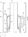
FIG. 10 is a side sectional illustration of the monolithic vehicle component with an open aft end. -
FIG. 1 illustrates anassembly 20 for an aerial vehicle such as, but not limited to, an unmanned aerial vehicle (UAV), a drone or any other manned or unmanned aircraft or self-propelled projectile. Thevehicle assembly 20 ofFIG. 1 includes agas turbine engine 22, avehicle body 24 and anengine support structure 26 coupling thegas turbine engine 22 to thevehicle body 24. - The
gas turbine engine 22 ofFIG. 1 is configured as a single spool, radial-flow turbojet gas turbine engine. Thisgas turbine engine 22 is configured for propelling the aerial vehicle. The present disclosure, however, is not limited to such an exemplary turbojet gas turbine engine configuration nor to a vehicle propulsion system application. For example, thegas turbine engine 22 may alternatively be configured as an auxiliary power unit (APU) for the aerial vehicle. - The
gas turbine engine 22 ofFIG. 1 extends axially along anaxial centerline 28 between a forward,upstream airflow inlet 30 into thegas turbine engine 22 and an aft,downstream exhaust 32 out of thegas turbine engine 22. Thisaxial centerline 28 may be a centerline axis of thegas turbine engine 22, thevehicle body 24 and/or thesupport structure 26. Theaxial centerline 28 may also or alternatively be a rotational axis for one or more components within thegas turbine engine 22. - The
gas turbine engine 22 includes acore flowpath 34, aninlet section 36, a (e.g., radial flow)compressor section 37, a (e.g., reverse flow)combustor section 38, a (e.g., radial flow)turbine section 39 and anexhaust section 40. Thegas turbine engine 22 also includes astatic engine structure 42 housing and/or forming one or more or all of the engine section 36-40. - The
core flowpath 34 extends within thegas turbine engine 22 between theengine inlet 30 and theengine exhaust 32. More particularly, thecore flowpath 34 extends sequentially through theinlet section 36, thecompressor section 37, thecombustor section 38, theturbine section 39 and theexhaust section 40 from theengine inlet 30 to theengine exhaust 32. - The
compressor section 37 includes abladed compressor rotor 44. Theturbine section 39 includes a bladed turbine rotor 46. Each of theseengine rotors 44, 46 includes a plurality of rotor blades arranged circumferentially around and connected to at least one respective rotor disk and/or hub. The rotor blades, for example, may be formed integral with or mechanically fastened, welded, brazed, adhered and/or otherwise attached to the respective rotor disk(s) and/or hub(s). - The
compressor rotor 44 may be configured as a radial flow compressor rotor. The turbine rotor 46 may be configured as a radial flow turbine rotor. Thecompressor rotor 44 is connected to the turbine rotor 46 through anengine shaft 48. Thisengine shaft 48 is rotatably supported by thestatic engine structure 42 through a plurality ofbearings - The
combustor section 38 includes anannular combustor 52 with anannular combustion chamber 54. Thecombustor 52 ofFIG. 1 is configured as a reverse flow combustor.Inlets ports 56 / flow tubes into thecombustion chamber 54, for example, may be arranged at (e.g., on, adjacent or proximate) and/or towards anaft bulkhead wall 58 of thecombustor 52. An outlet from thecombustor 52 may be arranged axially aft of an inlet to theturbine section 39. Thecombustor 52 may also be arranged radially outboard of and/or axially overlap at least a (e.g., aft) portion of theturbine section 39. With this arrangement, thecore flowpath 34 ofFIG. 1 reverses direction (e.g., from a forward-to-aft direction to an aft-to-forward direction) a first time as thecore flowpath 34 extends from adiffuser plenum 60 surrounding thecombustor 52 into thecombustion chamber 54. The core flowpath 34 ofFIG. 1 then reverses direction (e.g., from the aft-to-forward direction to the forward-to-aft direction) a second time as thecore flowpath 34 extends from thecombustion chamber 54 into theturbine section 39. - During operation, air enters the
gas turbine engine 22 through theinlet section 36 and itsengine inlet 30. Theinlet section 36 directs this air from theengine inlet 30 into thecore flowpath 34 and thecompressor section 37. The air within thecore flowpath 34 may be referred to as core air. This core air is compressed by thecompressor rotor 44 and directed through adiffuser 62 and itsplenum 60 into thecombustion chamber 54. Fuel is injected and mixed with the compressed core air to provide a fuel-air mixture. This fuel-air mixture is ignited within thecombustion chamber 54, and combustion products thereof flow through theturbine section 39 and cause the turbine rotor 46 to rotate. The rotation of the turbine rotor 46 drives rotation of thecompressor rotor 44 and, thus, compression of the air received from theengine inlet 30. Theexhaust section 40 receives the combustion products from theturbine section 39. Theexhaust section 40 directs the received combustion products out of thegas turbine engine 22 to provide forward engine thrust. - The
static engine structure 42 ofFIG. 1 includes one or morestationary structures 64 and 66. Thesestationary structures 64 and 66 are configured as discrete sub-structures (e.g., axial sections) of thestatic engine structure 42. The forward, upstream stationary structure 64 and/or the aft, downstreamstationary structure 66 may each be formed as (or part of) a monolithic body 68, 70 (e.g., a monolithic vehicle component), respectively. Herein, the term "monolithic" may describe a component of the vehicle which is formed as a single unitary body. Eachstationary structure 64, 66, for example, may be additively manufactured, cast, machined and/or otherwise formed as an integral, unitary body. By contrast, a non-monolithic body may include parts that are discretely formed from one another, where those parts are subsequently mechanically fastened and/or otherwise attached to one another. - The upstream stationary structure 64 may form a section of the
static engine structure 42 along any one or more or all of theengine sections FIG. 1 , for example, includes aninlet nozzle 72 and at least a forward, upstream section (or an entirety) of acompressor case 74. The upstream stationary structure 64 may also include an internal support structure for at least one of the bearings 50; e.g., the forward bearing 50A. - The
inlet nozzle 72 is disposed within theinlet section 36, for example, at theengine inlet 30. Thisinlet nozzle 72 may be configured to condition the core air entering thecompressor section 37. Theinlet nozzle 72 ofFIG. 1 , for example, includes one or moreinlet guide vanes 76 configured to impart swirl to the core air. Theseinlet guide vanes 76 are arranged circumferentially about theaxial centerline 28 in an annular array; e.g., an inlet nozzle vane array. Each of theinlet guide vanes 76 extends radially across thecore flowpath 34 between and is connected to aninner platform 78 of theinlet nozzle 72 and anouter platform 80 of theinlet nozzle 72. - The
compressor case 74 houses thecompressor section 37 and itscompressor rotor 44. Thecompressor case 74, for example, extends circumferentially about (e.g., circumscribes) and axially overlaps thecompressor rotor 44. Thecompressor case 74 may thereby form an outer peripheral boundary of thecore flowpath 34 within thecompressor section 37. - The downstream
stationary structure 66 may form a section of thestatic engine structure 42 along any one or more or all of the engine sections 38-40. The downstreamstationary structure 66 ofFIG. 1 , for example, includes adiffuser nozzle 82, an outer diffuser (e.g., plenum)case 84, thecombustor 52, aturbine nozzle 86, aturbine case 88 and anexhaust case 90. The downstreamstationary structure 66 may also include an internal support structure for at least one of the bearings 50; e.g., the aft bearing 50B. - The
diffuser nozzle 82 is disposed within thediffuser 62 upstream of theplenum 60. Thisdiffuser nozzle 82 may be configured to condition the core air leaving thecompressor section 37 and entering theplenum 60. Thediffuser nozzle 82 ofFIG. 1 , for example, includes one or morediffuser guide vanes 92 configured to impart swirl to the core air. Thesediffuser guide vanes 92 are arranged circumferentially about theaxial centerline 28 in an annular array; e.g., a diffuser nozzle vane array. Each of thediffuser guide vanes 92 extends radially across thecore flowpath 34 between and is connected to aninner platform 94 of thediffuser nozzle 82 and anouter platform 96 of thediffuser nozzle 82. - The
diffuser case 84 houses thecombustor 52 within thecombustor section 38. Thediffuser case 84, for example, extends circumferentially about (e.g., circumscribes), axially overlaps and is spaced radially outward from thecombustor 52. Thediffuser case 84 may thereby form an outer peripheral boundary of thecore flowpath 34 and theplenum 60 along thecombustor 52. Theouter platform 96 of thediffuser nozzle 82 may be formed as a forward, upstream extension of thediffuser case 84. - The
combustor 52 ofFIG. 1 includes anouter combustor wall 98, aninner combustor wall 100 and thebulkhead wall 58. Theouter combustor wall 98 extends axially between and may be connected to anouter platform 102 of theturbine nozzle 86 and thebulkhead wall 58. Theouter combustor wall 98 extends circumferentially about (e.g., circumscribes), axially overlaps and is spaced radially outward from theinner combustor wall 100. Theinner combustor wall 100 extends axially between aninner platform 104 of theturbine nozzle 86 and thebulkhead wall 58, and theinner combustor wall 100 may be connected to thebulkhead wall 58. Theinner combustor wall 100 extends circumferentially about (e.g., circumscribes), axially overlaps and is spaced radially outward from theturbine case 88. Thebulkhead wall 58 extends radially between theouter combustor wall 98 and theinner combustor wall 100, at aft ends of thecombustor walls combustor walls combustion chamber 54 within thecombustor 52. - The
turbine nozzle 86 is disposed within theturbine section 39, for example, at an intersection between thecombustor section 38 and theturbine section 39. Thisturbine nozzle 86 may be configured to condition the combustion products leaving thecombustor section 38 and itscombustion chamber 54 and entering theturbine section 39. Theturbine nozzle 86 ofFIG. 1 , for example, includes one or moreturbine guide vanes 106 configured to impart swirl to the combustion products. Theseturbine guide vanes 106 are arranged circumferentially about theaxial centerline 28 in an annular array; e.g., a turbine nozzle vane array. Each of theturbine guide vanes 106 extends radially across thecore flowpath 34 between and is connected to theinner platform 104 of theturbine nozzle 86 and theouter platform 102 of theturbine nozzle 86. - The
turbine case 88 houses at least a portion of theturbine section 39 and its turbine rotor 46. Theturbine case 88, for example, extends circumferentially about (e.g., circumscribes) and axially overlaps at least a (e.g., an aft, downstream) portion of the turbine rotor 46. Theturbine case 88 may thereby form an outer peripheral boundary of thecore flowpath 34 within at least (e.g., an aft, downstream) portion of thecompressor section 37. - The
exhaust case 90 extends axially between and to one or more of theengine cases engine exhaust 32. Theexhaust case 90 may also be connected to thediffuser case 84 and/or theturbine case 88 at aft ends thereof. Theexhaust case 90 extends circumferentially about (e.g., completely around) theaxial centerline 28. Theexhaust case 90 may thereby form an outer peripheral boundary of thecore flowpath 34 within theexhaust section 40 to theengine exhaust 32. - An aft, downstream end of the upstream stationary structure 64 is mated with and connected to a forward, upstream end of the downstream
stationary structure 66. The upstream stationary structure 64 ofFIG. 1 , for example, is attached to the downstreamstationary structure 66 by at least one mechanical joint; e.g., a bolted flange connection. However, in other embodiments, the upstream stationary structure 64 may also or alternatively be attached to the downstreamstationary structure 66 by at least one bond joint; e.g., a braze connection, a welded connection, etc. - The
vehicle body 24 is configured to (e.g., completely) house thegas turbine engine 22. Thevehicle body 24 may also be configured to form an outer (e.g., exterior)aerodynamic surface 108 for the vehicle; see alsoFIG. 2 . Thevehicle body 24, for example, may be configured as a nacelle for thegas turbine engine 22. Thevehicle body 24 may also or alternatively be configured as a fuselage and/or another airframe component for the vehicle. - The
vehicle body 24 ofFIG. 1 includes a plurality of sections 110-112; e.g., generally tubular exterior vehicle walls. Thefirst body section 110 may be configured as a forward, upstream section of thevehicle body 24. Thesecond body section 111 may be configured as an intermediate section of thevehicle body 24. Thethird body section 112 may be configured as an aft, downstream section of thevehicle body 24. - Each of the
body sections axial centerline 28 providing thatrespective body section first body section 110 and thesecond body section 111 ofFIG. 1 may each extends circumferentially about (e.g., circumscribe) and axially along (e.g., overlap) thegas turbine engine 22. Thesecond body section 111, in particular, extends axially along theaxial centerline 28 between a forward,upstream end 114 of thesecond body section 111 and an aft,downstream end 116 of thesecond body section 111. Theupstream end 114 of thesecond body section 111 may be axially aligned with (or disposed axially near) an interface between thestationary structures 64 and 66. Thedownstream end 116 of thesecond body section 111 may be axially aligned with (or disposed axially near) theengine exhaust 32. Thefirst body section 110 may be attached to thesecond body section 111 at theupstream end 114 of thesecond body section 111 through a mechanical joint; e.g., a bolted flange coupling. Thethird body section 112 may be attached to thesecond body section 111 at thedownstream end 116 of thesecond body section 111 through a mechanical joint; e.g., a bolted flange coupling. Of course, in other embodiments, thesecond body section 111 may also or alternatively be attached to thefirst body section 110 and/or thethird body section 112 through a bond connection; e.g., a brazed connection, a welded connection, etc. - The
support structure 26 is configured to support and locate thegas turbine engine 22 within thevehicle body 24. Thesupport structure 26 ofFIG. 1 , for example, extends radially between and is connected to (1) thestatic engine structure 42 and its downstreamstationary structure 66 and (2) thevehicle body 24 and itssecond body section 111. Thesupport structure 26 thereby (e.g., directly) connects thestatic engine structure 42 and its downstreamstationary structure 66 to thevehicle body 24 and itssecond body section 111. The downstreamstationary structure 66 may connect the upstream stationary structure 64 to thesupport structure 26. Thesupport structure 26 may thereby also (e.g., indirectly) connect the upstream stationary structure 64 to thevehicle body 24 and itssecond body section 111. - The
support structure 26 ofFIG. 1 is formed integral with the downstreamstationary structure 66 and thesecond body section 111 as part of themonolithic body 70; e.g., the monolithic vehicle component. Thesupport structure 26, the downstreamstationary structure 66 and thesecond body section 111, for example, may be additively manufactured, cast, machined and/or otherwise formed together as a common integral, unitary body. Such a configuration facilitates integrating thegas turbine engine 22 into a (e.g., monocoque) power module. The vehicle may thereby be readily provided with different power module configurations (e.g., thrust ratings, mission ranges, etc.) based on, for example, specific mission requirements, etc. Power modules may also be readily swapped out for maintenance, repair, etc. when needed. Furthermore, providing themonolithic body 70 may reduce complexity and/or a part count for the vehicle, which may in turn reduce manufacturing and/or assembly costs of the vehicle. - In some embodiments, referring to
FIGS. 3 and4 , thesupport structure 26 may include one ormore support members FIG. 3 , at least some (or all) of the support members 118 may be distributed circumferentially about thegas turbine engine 22 and its downstreamstationary structure 66; e.g., in at least one circumferentially extending array (or multiple arrays). The support members 118 may thereby support thegas turbine engine 22 and its downstreamstationary structure 66 at multiple locations in a reference plane, for example, perpendicular to theaxial centerline 28. Referring toFIG. 4 , at least some (or all) of the support members 118 may also or alternatively be distributed axially along thegas turbine engine 22 and its downstreamstationary structure 66; e.g., in at least one axially extending array (or multiple arrays). The support members 118 may thereby support thegas turbine engine 22 and its downstreamstationary structure 66 at multiple locations in a reference plane, for example, parallel to and/or containing theaxial centerline 28. Furthermore, with the support member arrangement ofFIGS. 3 and4 , thesupport structure 26 and its support members 118 may (e.g., directly) support a central region of and/or center of mass of thegas turbine engine 22. - In some embodiments, one or more of the
support members 118A may each be configured as or otherwise includes astrut 120. Examples of thestrut 120 include, but are not limited to, a stanchion, a ligament, a post, etc. Eachstrut 120 extends radially between the downstreamstationary structure 66 and thesecond body section 111. Eachstrut 120 is connected (e.g., directly or indirectly) to the downstreamstationary structure 66 and thesecond body section 111. For example, eachstrut 120 may be individually connected to the downstreamstationary structure 66. A grouping of thestruts 120, however, may be collectively connected to thesecond body section 111 through a common (e.g., the same) support member base; e.g., a trunk. Of course, in other embodiments, thestruts 120 may be individually (e.g., discretely, separately, etc.) connected to thesecond body section 111 and/or the grouping of thestruts 120 may be collectively connected to the downstreamstationary structure 66 through a common (e.g., the same) support member base. - In some embodiments, referring to
FIG. 5 , one or more of the support members 118 may each be configured with a solid body; e.g., without any internal voids, passages, etc. In other embodiments, referring toFIG. 6 , one or more of the support members 118 may each include an outer (e.g., exterior)wall 122 which forms at least one internal volume 124 (e.g., a passage, a cavity, etc.) within the respective support member 118. Thisinternal volume 124 may be empty. Alternatively, referring toFIG. 7 , theinternal volume 124 may be partially or completely filled with a filler 126 (e.g., a porous structure) such as, but not limited to, a lattice structure (e.g., seeFIGS. 8A and 8B ) or foam. - In some embodiments, referring to
FIG. 1 , at least one of the support members 118 (e.g., 118B) may be configured with or at least partially form afluid reservoir 128 for the vehicle; e.g., for thegas turbine engine 22. Thesupport member 118B ofFIG. 1 , for example, is configured with an integral, internal fuel reservoir for thegas turbine engine 22. This fuel reservoir is formed by an internal volume 130 (e.g., open cavity) within thesupport member 118B. Thesupport member 118B ofFIG. 1 may thereby perform multiple functions including locating thegas turbine engine 22, supporting thegas turbine engine 22 and storing fuel (or another fluid or substance) for use in gas turbine engine operation; e.g., during gas turbine engine start up. - In some embodiments, referring to
FIG. 9 , the monolithic (e.g., power module)body 70 may be configured with a closed aft end. Themonolithic body 70 ofFIG. 9 , for example, may also include an (e.g., annular) endwall 132 that extends radially between and is connected to thesecond body section 111 and theexhaust case 90 at, for example, aft, downstream ends thereof. In other embodiments however, referring toFIG. 10 , themonolithic body 70 may be configured with an open aft end. Themonolithic body 70, for example, may be configured without theendwall 132. - Each
monolithic body 68, 70 may be additively manufactured using an additive manufacturing apparatus. Examples of the additive manufacturing apparatus include, but are not limited to, an energy (e.g., laser or electron) beam powder bed fusion (PBF) apparatus, a stereolithography (SLA) apparatus, a direct selective laser sintering (DSLS) apparatus, an electron beam sintering (EBS) apparatus, an electron beam melting (EBM) apparatus, a laser engineered net shaping (LENS) apparatus, a laser net shape manufacturing (LNSM) apparatus, a direct metal deposition (DMD) apparatus, a direct metal laser sintering (DMLS) apparatus or any other type of additive manufacturing apparatus. However, while themonolithic body 68, 70 may be formed using the additive manufacturing apparatus, themonolithic body 68, 70 may also or alternatively be formed using one or more other manufacturing processes. - The
gas turbine engine 22 is described above as a single spool, radial-flow turbojet gas turbine engine for ease of description. The present disclosure, however, is not limited to such an exemplary gas turbine engine. Thegas turbine engine 22, for example, may alternatively be configured as an axial flow gas turbine engine. Thegas turbine engine 22 may be configured as a direct drive gas turbine engine. Thegas turbine engine 22 may alternatively include a gear train that connects one or more rotors together such that the rotors rotate at different speeds. Thegas turbine engine 22 may be configured with a single spool (e.g., seeFIG. 1 ), two spools, or with more than two spools. Thegas turbine engine 22 may be configured as a turbofan engine, a turbojet engine, a turboprop engine, a turboshaft engine, a propfan engine, a pusher fan engine or any other type of turbine engine. In addition, while thegas turbine engine 22 is described above with an exemplary reverse flow annular combustor, thegas turbine engine 22 may also or alternatively include any other type / configuration of annular, tubular (e.g., CAN), axial flow and/or reverse flow combustor. The present disclosure therefore is not limited to any particular types or configurations of gas turbine engines. - While various embodiments of the present disclosure have been described, it will be apparent to those of ordinary skill in the art that many more embodiments and implementations are possible within the scope of the disclosure. For example, the present disclosure as described herein includes several aspects and embodiments that include particular features. Although these features may be described individually, it is within the scope of the present disclosure that some or all of these features may be combined with any one of the aspects and remain within the scope of the disclosure. Accordingly, the present disclosure is not to be restricted except in light of the attached claims and their equivalents.
Claims (15)
- An assembly (20) for an aerial vehicle, the assembly (20) comprising:a vehicle body (24) comprising a body section (111);a gas turbine engine (22) comprising a stationary structure (66), the gas turbine engine (22) housed within the vehicle body (24); anda support structure (26) extending between and connected to the body section (111) and the stationary structure (66), the support structure (26) supporting the gas turbine engine (22) within the vehicle body (24), the body section (111), the stationary structure (66) and the support structure (26) included in a monolithic body (70).
- The assembly (20) of claim 1, wherein the body section (111) is spaced radially out from, extends circumferentially about and extends axially along the gas turbine engine (22).
- The assembly (20) of claim 1 or 2, wherein the body section (111) partially forms an outer aerodynamic surface (108) of the aerial vehicle.
- The assembly (20) of any preceding claim, wherein the vehicle body (24) comprises at least one of a fuselage or a nacelle.
- The assembly (20) of any preceding claim, wherein the stationary structure (66) at least partially houses a rotating structure within the gas turbine engine (22), and optionally wherein:the rotating structure comprises a turbine rotor (46); andthe stationary structure (66) houses the turbine rotor (46).
- The assembly (20) of any preceding claim, wherein the stationary structure (66) comprises a combustor (52) within the gas turbine engine (22).
- The assembly (20) of any preceding claim, wherein the stationary structure (66) comprises a vane array (92; 106) within the gas turbine engine (22).
- The assembly (20) of any preceding claim, wherein the stationary structure (66) comprises:a diffuser case (84);a turbine case (88); and/oran exhaust case (90).
- The assembly (20) of any preceding claim, wherein the support structure (26) includes a plurality of support members (118) radially between the body section (111) and the stationary structure (66), and optionally wherein:the plurality of support members (118) are distributed circumferentially about the gas turbine engine (22); and/orthe plurality of support members (118) are distributed axially along the gas turbine engine (22).
- The assembly (20) of claim 9, wherein at least one of the plurality of support members (118A) comprises a strut (120).
- The assembly (20) of claim 9 or 10, wherein at least one of the plurality of support members (118B) comprises a fuel reservoir (128) for the gas turbine engine (22).
- The assembly (20) of any preceding claim, wherein the support structure (26) forms a fluid reservoir (128) for the gas turbine engine (22) radially between the gas turbine engine (22) and the body section (111).
- The assembly (20) of any preceding claim, wherein the stationary structure (66) comprises:a downstream stationary structure (66); andan upstream stationary structure (64) mechanically attached to the downstream stationary structure (66), the upstream stationary structure (64) forming an inlet section (36) of the gas turbine engine (22).
- An assembly (20) for an aerial vehicle, comprising:a vehicle body (24);a gas turbine engine (22) comprising a stationary structure (66), the gas turbine engine (22) housed within the vehicle body (24); anda plurality of support members (118) extending between and connected to the vehicle body (24) and the stationary structure (66), the plurality of support members (118) locating and supporting the gas turbine engine (22) within the vehicle body (24), at least the stationary structure (66) and the plurality of support members (118) formed together in a monolithic body (70),optionally wherein:the vehicle body (24) comprises a tubular body section (111), and at least the tubular body section (111), the stationary structure (66) and the plurality of support members (118) are formed together in the monolithic body (70); and/orthe plurality of support members (118) comprise a first support member (118B), and the first support member (118B) comprises a fluid reservoir (128).
- An assembly (20) for an aerial vehicle, comprising:a vehicle body (24);a gas turbine engine (22) including a stationary structure (66) and a rotating structure at least partially housed within the stationary structure (66), the gas turbine engine (22) housed within the vehicle body (24); anda support structure (26) extending between and connected to the vehicle body (24) and the stationary structure (66), the support structure (26) supporting the gas turbine engine (22) within the vehicle body (24), and the support structure (26) comprising an integral fluid reservoir (128) between the gas turbine engine (22) and the vehicle body (24).
Priority Applications (1)
| Application Number | Priority Date | Filing Date | Title |
|---|---|---|---|
| EP26162045.4A EP4725841A2 (en) | 2022-09-02 | 2023-09-04 | Vehicle component with integrated engine support structure and body section |
Applications Claiming Priority (1)
| Application Number | Priority Date | Filing Date | Title |
|---|---|---|---|
| US17/902,282 US20240076049A1 (en) | 2022-09-02 | 2022-09-02 | Vehicle component with integrated engine support structure and body section |
Related Child Applications (1)
| Application Number | Title | Priority Date | Filing Date |
|---|---|---|---|
| EP26162045.4A Division EP4725841A2 (en) | 2022-09-02 | 2023-09-04 | Vehicle component with integrated engine support structure and body section |
Publications (2)
| Publication Number | Publication Date |
|---|---|
| EP4331994A1 true EP4331994A1 (en) | 2024-03-06 |
| EP4331994B1 EP4331994B1 (en) | 2026-03-04 |
Family
ID=87930144
Family Applications (2)
| Application Number | Title | Priority Date | Filing Date |
|---|---|---|---|
| EP26162045.4A Pending EP4725841A2 (en) | 2022-09-02 | 2023-09-04 | Vehicle component with integrated engine support structure and body section |
| EP23195230.0A Active EP4331994B1 (en) | 2022-09-02 | 2023-09-04 | Vehicle component with integrated engine support structure and body section |
Family Applications Before (1)
| Application Number | Title | Priority Date | Filing Date |
|---|---|---|---|
| EP26162045.4A Pending EP4725841A2 (en) | 2022-09-02 | 2023-09-04 | Vehicle component with integrated engine support structure and body section |
Country Status (2)
| Country | Link |
|---|---|
| US (1) | US20240076049A1 (en) |
| EP (2) | EP4725841A2 (en) |
Families Citing this family (2)
| Publication number | Priority date | Publication date | Assignee | Title |
|---|---|---|---|---|
| US12297777B1 (en) * | 2023-11-09 | 2025-05-13 | Xiny Structural Consultants | Jet engine |
| EP4636228A1 (en) * | 2024-04-19 | 2025-10-22 | TGM Kanis Turbinen GmbH | Additive manufacturing in metal underframes for plants |
Citations (4)
| Publication number | Priority date | Publication date | Assignee | Title |
|---|---|---|---|---|
| EP0490470A1 (en) * | 1990-12-14 | 1992-06-17 | Williams International Corporation | Integrated propulsion system |
| US20100155525A1 (en) * | 2008-12-24 | 2010-06-24 | Alan Roy Stuart | Monolithic structure for mounting aircraft engine |
| EP3670865A1 (en) * | 2018-12-17 | 2020-06-24 | United Technologies Corporation | Attritable engine integrated with vehicle |
| EP4187155A1 (en) * | 2021-11-24 | 2023-05-31 | Raytheon Technologies Corporation | Sectioned engine structure for a gas turbine engine |
Family Cites Families (15)
| Publication number | Priority date | Publication date | Assignee | Title |
|---|---|---|---|---|
| US3809340A (en) * | 1972-12-26 | 1974-05-07 | A Dolgy | Devices for mounting an engine on an aircraft pylon |
| US8205825B2 (en) * | 2008-02-27 | 2012-06-26 | Spirit Aerosystems, Inc. | Engine pylon made from composite material |
| US20110239656A1 (en) * | 2010-04-02 | 2011-10-06 | Matthew Crume | Water Augmentation System |
| US9889930B2 (en) * | 2014-11-24 | 2018-02-13 | Amazon Technologies, Inc. | Unmanned aerial vehicle protective frame configuration |
| GB2537935B (en) * | 2015-05-01 | 2021-02-24 | Intelligent Energy Ltd | Aerial vehicle |
| US9863368B1 (en) * | 2016-09-09 | 2018-01-09 | Florida Turbine Technologies, Inc. | Aircraft with gas turbine engine having outer bypass elements removed |
| US20180362171A1 (en) * | 2017-06-15 | 2018-12-20 | Donald Butler Curchod | Advanced drag reduction system for jet aircraft |
| FR3072945B1 (en) * | 2017-10-27 | 2020-11-20 | Airbus Operations Sas | PRIMARY STRUCTURE OF SUPPORT MAST OF AN AIRCRAFT POWER UNIT WITH A LOWER U-SHAPED PART OBTAINED MONOBLOC OR BY WELDING |
| US10697370B2 (en) * | 2018-08-30 | 2020-06-30 | Rolls-Royce North American Technologies Inc. | Oil supply assembly for gas turbine engine |
| US11156156B2 (en) * | 2018-10-04 | 2021-10-26 | Raytheon Technologies Corporation | Gas turbine engine with a unitary structure and method for manufacturing the same |
| CN111216901A (en) * | 2018-11-26 | 2020-06-02 | 本田技研工业株式会社 | Power supply device and flying object |
| US11761855B2 (en) * | 2019-07-03 | 2023-09-19 | Rtx Corporation | Apparatus and method for testing additively manufactured engine components |
| US11661895B2 (en) * | 2020-02-24 | 2023-05-30 | General Electric Comapny | Autonomous safety mode for distributed control of turbomachines |
| US11713695B2 (en) * | 2020-05-11 | 2023-08-01 | Raytheon Technologies Corporation | Unitized manufacturing of a gas turbine engine |
| US11634232B1 (en) * | 2022-04-30 | 2023-04-25 | Beta Air, Llc | Hybrid propulsion systems for an electric aircraft |
-
2022
- 2022-09-02 US US17/902,282 patent/US20240076049A1/en active Pending
-
2023
- 2023-09-04 EP EP26162045.4A patent/EP4725841A2/en active Pending
- 2023-09-04 EP EP23195230.0A patent/EP4331994B1/en active Active
Patent Citations (4)
| Publication number | Priority date | Publication date | Assignee | Title |
|---|---|---|---|---|
| EP0490470A1 (en) * | 1990-12-14 | 1992-06-17 | Williams International Corporation | Integrated propulsion system |
| US20100155525A1 (en) * | 2008-12-24 | 2010-06-24 | Alan Roy Stuart | Monolithic structure for mounting aircraft engine |
| EP3670865A1 (en) * | 2018-12-17 | 2020-06-24 | United Technologies Corporation | Attritable engine integrated with vehicle |
| EP4187155A1 (en) * | 2021-11-24 | 2023-05-31 | Raytheon Technologies Corporation | Sectioned engine structure for a gas turbine engine |
Also Published As
| Publication number | Publication date |
|---|---|
| US20240076049A1 (en) | 2024-03-07 |
| EP4725841A2 (en) | 2026-04-15 |
| EP4331994B1 (en) | 2026-03-04 |
Similar Documents
| Publication | Publication Date | Title |
|---|---|---|
| US12078077B2 (en) | Sectioned engine structure for a gas turbine engine | |
| US11156156B2 (en) | Gas turbine engine with a unitary structure and method for manufacturing the same | |
| EP4331994B1 (en) | Vehicle component with integrated engine support structure and body section | |
| EP4414608A2 (en) | Turbine engine fuel injector with oxygen circuit | |
| US20230407767A1 (en) | Split case structure for a gas turbine engine | |
| EP4484826A1 (en) | Turbine engine support structure with airflow ports | |
| EP2472070A2 (en) | Methods of manufacturing a gas turbine engine case and corresponding case | |
| EP4343134A2 (en) | Gas turbine engine with integral bypass duct | |
| US12398662B2 (en) | Gas turbine engine support structure with internal lattice | |
| EP4678901A2 (en) | Gas turbine engine with integral actuation system | |
| US12264624B2 (en) | Build plate integrated into additive manufactured component | |
| EP4715185A1 (en) | Additively manufactured annular fuel manifold | |
| CN114483220A (en) | Turbine engine bearing arrangement | |
| US12535212B2 (en) | Acoustic liner for a gas turbine engine | |
| EP4495383A1 (en) | Turbine engine vane array structure with air particle separator | |
| EP4481160A1 (en) | Support structure for forming turbine engine rotating structure | |
| EP4715184A1 (en) | Flow assisted integral splash plate | |
| EP4685341A1 (en) | Diffuser-turbine flow network | |
| EP4592510A1 (en) | Intermediate case for aircraft propulsion system housing |
Legal Events
| Date | Code | Title | Description |
|---|---|---|---|
| PUAI | Public reference made under article 153(3) epc to a published international application that has entered the european phase |
Free format text: ORIGINAL CODE: 0009012 |
|
| STAA | Information on the status of an ep patent application or granted ep patent |
Free format text: STATUS: THE APPLICATION HAS BEEN PUBLISHED |
|
| AK | Designated contracting states |
Kind code of ref document: A1 Designated state(s): AL AT BE BG CH CY CZ DE DK EE ES FI FR GB GR HR HU IE IS IT LI LT LU LV MC ME MK MT NL NO PL PT RO RS SE SI SK SM TR |
|
| STAA | Information on the status of an ep patent application or granted ep patent |
Free format text: STATUS: REQUEST FOR EXAMINATION WAS MADE |
|
| 17P | Request for examination filed |
Effective date: 20240906 |
|
| RBV | Designated contracting states (corrected) |
Designated state(s): AL AT BE BG CH CY CZ DE DK EE ES FI FR GB GR HR HU IE IS IT LI LT LU LV MC ME MK MT NL NO PL PT RO RS SE SI SK SM TR |
|
| GRAP | Despatch of communication of intention to grant a patent |
Free format text: ORIGINAL CODE: EPIDOSNIGR1 |
|
| STAA | Information on the status of an ep patent application or granted ep patent |
Free format text: STATUS: GRANT OF PATENT IS INTENDED |
|
| INTG | Intention to grant announced |
Effective date: 20250509 |
|
| GRAJ | Information related to disapproval of communication of intention to grant by the applicant or resumption of examination proceedings by the epo deleted |
Free format text: ORIGINAL CODE: EPIDOSDIGR1 |
|
| STAA | Information on the status of an ep patent application or granted ep patent |
Free format text: STATUS: REQUEST FOR EXAMINATION WAS MADE |
|
| GRAP | Despatch of communication of intention to grant a patent |
Free format text: ORIGINAL CODE: EPIDOSNIGR1 |
|
| STAA | Information on the status of an ep patent application or granted ep patent |
Free format text: STATUS: GRANT OF PATENT IS INTENDED |
|
| INTC | Intention to grant announced (deleted) | ||
| INTG | Intention to grant announced |
Effective date: 20250929 |
|
| GRAS | Grant fee paid |
Free format text: ORIGINAL CODE: EPIDOSNIGR3 |
|
| GRAA | (expected) grant |
Free format text: ORIGINAL CODE: 0009210 |
|
| STAA | Information on the status of an ep patent application or granted ep patent |
Free format text: STATUS: THE PATENT HAS BEEN GRANTED |
|
| AK | Designated contracting states |
Kind code of ref document: B1 Designated state(s): AL AT BE BG CH CY CZ DE DK EE ES FI FR GB GR HR HU IE IS IT LI LT LU LV MC ME MK MT NL NO PL PT RO RS SE SI SK SM TR |
|
| REG | Reference to a national code |
Ref country code: CH Ref legal event code: F10 Free format text: ST27 STATUS EVENT CODE: U-0-0-F10-F00 (AS PROVIDED BY THE NATIONAL OFFICE) Effective date: 20260304 Ref country code: GB Ref legal event code: FG4D |
|
| REG | Reference to a national code |
Ref country code: DE Ref legal event code: R096 Ref document number: 602023012901 Country of ref document: DE |
|
| REG | Reference to a national code |
Ref country code: IE Ref legal event code: FG4D |