EP4331972A1 - Electric marine propulsion system and control method with voltage adaptation - Google Patents
Electric marine propulsion system and control method with voltage adaptation Download PDFInfo
- Publication number
- EP4331972A1 EP4331972A1 EP23191674.3A EP23191674A EP4331972A1 EP 4331972 A1 EP4331972 A1 EP 4331972A1 EP 23191674 A EP23191674 A EP 23191674A EP 4331972 A1 EP4331972 A1 EP 4331972A1
- Authority
- EP
- European Patent Office
- Prior art keywords
- voltage
- motor
- change
- electric motor
- demand
- Prior art date
- Legal status (The legal status is an assumption and is not a legal conclusion. Google has not performed a legal analysis and makes no representation as to the accuracy of the status listed.)
- Granted
Links
Images



Classifications
-
- B—PERFORMING OPERATIONS; TRANSPORTING
- B63—SHIPS OR OTHER WATERBORNE VESSELS; RELATED EQUIPMENT
- B63H—MARINE PROPULSION OR STEERING
- B63H21/00—Use of propulsion power plant or units on vessels
- B63H21/12—Use of propulsion power plant or units on vessels the vessels being motor-driven
- B63H21/17—Use of propulsion power plant or units on vessels the vessels being motor-driven by electric motor
-
- B—PERFORMING OPERATIONS; TRANSPORTING
- B63—SHIPS OR OTHER WATERBORNE VESSELS; RELATED EQUIPMENT
- B63H—MARINE PROPULSION OR STEERING
- B63H21/00—Use of propulsion power plant or units on vessels
- B63H21/21—Control means for engine or transmission, specially adapted for use on marine vessels
-
- B—PERFORMING OPERATIONS; TRANSPORTING
- B63—SHIPS OR OTHER WATERBORNE VESSELS; RELATED EQUIPMENT
- B63H—MARINE PROPULSION OR STEERING
- B63H21/00—Use of propulsion power plant or units on vessels
- B63H21/21—Control means for engine or transmission, specially adapted for use on marine vessels
- B63H2021/216—Control means for engine or transmission, specially adapted for use on marine vessels using electric control means
Definitions
- the present disclosure generally relates to marine propulsions systems, and more particularly to electric marine propulsion systems having electric motors and methods for controlling power utilization thereof.
- Electric propulsion systems comprising an electric motor rotating a propeller are known.
- on-board electric drive systems and outboard electric drive systems have been developed for propelling marine vessels.
- Different power supply arrangements for powering electric propulsion systems are also known.
- Such power storage systems include one or more batteries or banks of batteries, and or may include other storage devices such as one or more ultracapacitors, fuel cells, flow batteries, and/or other devices capable of storing and outputting electric energy.
- U.S. Patent No. 6,507,164 discloses a trolling motor having current based power management including: an electric motor; a motor controller having an output for providing voltage to the motor; and a current sensor for measuring the electrical current flowing through the motor.
- the motor controller Upon determining that the trolling motor has been operating above its continuous duty limit for a predetermined period of time, the motor controller begins reducing the voltage output to the motor until reaching an acceptable output voltage.
- the controller is operated in three distinct modes with three distinct sets of operating parameters, namely: a normal mode wherein the output is set to a commanded level; a current limit mode wherein the output is set to a safe, predetermined level; and a transitional mode wherein the output is incrementally changed from the predetermined level to the commanded level.
- U.S. Patent No. 6,902,446 discloses a DC motor having a motor housing and a motor controller housed within the motor housing.
- the heat producing components of the motor controller are in thermal communication with the housing such that the majority of the heat produced by such components will be readily conducted to the environment in which the motor is operating.
- the motor housing of the present invention When incorporated into a trolling motor, the motor housing of the present invention will be submerged so that controller produced heat will be dissipated into the water in which the trolling motor is operated.
- U.S. Patent No. 7,218,118 discloses a method for monitoring the condition of a battery of a marine propulsion system that provides the measuring of a voltage characteristic of the battery, comparing the voltage characteristic to a preselected threshold value, and evaluating the condition of the battery as a function of the relative magnitudes of the voltage characteristic and the threshold value.
- the voltage characteristic of the battery is measured subsequent to a connection event when a connection relationship between the battery and an electrical load is changed.
- the electrical load is typically a starter motor which is connected in torque transmitting relation with an internal combustion engine.
- the voltage characteristic is preferably measured at its minimum value during the inrush current episode immediately prior to cranking the internal combustion engine shaft to start the engine.
- U.S. Publication No. 2022/0194542 discloses a method of controlling an electric marine propulsion system configured to propel a marine vessel including measuring at least one parameter of an electric motor in the electric marine propulsion system and determining that the parameter measurement indicates an abnormality in the electric marine propulsion system. A reduced operation limit is then determined based on the at least one parameter measurement, wherein the reduced operation limit includes at least one of a torque limit, an RPM limit, a current limit, and a power limit. The electric motor is then controlled such that the reduced operation limit is not exceeded.
- the control system is configured to determine a voltage change due to a change in demand level of the electric motor, determine a minimum voltage at a maximum rated demand level for the electric motor based on the voltage change, determine an adjusted command for the electric motor based on the minimum voltage and a current demand input, and control the electric motor based on the adjusted command.
- One embodiment of a method of controlling an electric marine propulsion system wherein the marine propulsion system comprises at least one electric motor powered by a power storage system and configured to rotate a propulsor to propel a marine vessel, includes determining a voltage change due to a change in demand level of the electric motor and determining a minimum voltage at a maximum rated demand level for the electric motor based on the voltage change.
- An adjusted command for the electric motor is determined based on the minimum voltage and a current demand input, and the electric motor is controlled based on the adjusted command.
- the present inventors have recognized that electric marine propulsion poses additional challenges as compared with electric propulsion for land vehicles.
- One such challenge is the demand for electric marine propulsion systems with removable and interchangeable power storage systems, such as battery systems. Due to range issues and the time it takes to recharge a battery, there is a demand for electric drives that operate with a removable battery, where a vessel operator can have multiple batteries on board at a given time and swap to a new battery once a first battery is drained.
- marine environments are harsh and can cause damage to batteries, such as due to water exposure, and thus users may carry backup batteries in case of battery damage or failure of the first battery.
- Vessel owners may have multiple batteries in their fleet, some of which may not be by the original equipment manufacturer (OEM) of the marine drive.
- OEM original equipment manufacturer
- the propulsion control system may not be able to communicate with the power storage system, or a controller therefor, to obtain information about the battery state of health or charge level.
- the present inventors have recognized challenges arising in the instances where non-OEM batteries are used in place of OEM batteries in an electric marine propulsion system. When a non-OEM battery is connected to an electric marine propulsion system, the system is unable to communicate with the non-OEM battery in the way the that it does with an OEM battery. The resulting effect is that the parameters and specifications of the non-OEM battery are unknown to the propulsion control system, leading to an inability to properly regulate the marine drive and ensure operation of the drive within its capabilities.
- an OEM battery may lose communication functions, either due to a failure of the communication link, a controller malfunction, etc. Given that battery voltage changes as a battery is depleted and/or due to changes in the battery's state of health, loss of communication with the power storage system may also result in improper or inconsistent motor control or output.
- the inventors have recognized that propulsion control systems need a way to account for the voltage drop across a power storage system, including the connection elements between the propulsion system and the power storage system. Ascertaining the voltage drop is important because the power producing capacity of the motor changes as a function of input voltage. Thus, accounting for the voltage drop is important for appropriately effectuating a user's propulsion command, as well as for controlling the current delivery to the motor so as to remain within the motor specifications. Accordingly, the inventors developed the disclosed systems and methods which recognize voltage changes at the input of an electric motor to determine and implement a maximum output, prevent overcurrent events, and ensure a smooth derate as the voltage changes and the battery depletes.
- the inventors developed the disclosed system and method of controlling an electric marine propulsion system to enable the marine vessel to recognize changes in voltage as a result of changes in user demand and adapt the system to perform according to those readings when the system is being powered by one or more non-OEM batteries or one or more OEM batteries that have lost their ability to communicate with the system.
- the disclosed system and method are configured to facilitate the monitoring of a demand level of the user and inputs to the motor of the electric marine propulsion system and determine the maximum output the motor can produce at a rated torque.
- the control system may calculate an adapted system resistance and determine the maximum output the motor can produce at the rated torque after recognizing a change in the demand level of the user and measuring the change in demand level and a change in motor input voltage at each demand level.
- the maximum output may be effectuated as a minimum voltage, a maximum motor torque, a maximum motor speed (RPM), a maximum motor current or motor power consumed by one or more electric motors in the propulsion system, a maximum demand instruction permitted, a maximum vessel speed, or the like.
- the output limit may be automatically effectuated by the control system on the marine vessel such that each marine drive is controlled so as not to exceed the output limit.
- the one or more electric motors, or the power delivered thereto may be limited by the control system to ensure the marine vessel undergoes a steady derate process as the power in the battery depletes, make sure the motor does not output more than its rated torque, and calibrate the system to adjust current flow as voltage fluctuates.
- a user may increase the demand level at the helm by 10%.
- the system may be configured to measure an input voltage to the motor before and after the change, calculate the adapted system resistance from the input voltage and change in demand level, and use the adapted system resistance to determine the minimum voltage the motor would use at its rated torque. From the minimum voltage, the system can then calculate a maximum torque the motor should produce and constrain the system accordingly.
- the control system may also be configured to store a lookup table or command table and determine the maximum torque by identifying the torque value in the table corresponding to the determined minimum voltage.
- the system may also be configured to store recently calculated values, such as adapted system resistance, and assign weight to selected values to further smooth the derate process.
- FIG. 1 depicts an exemplary embodiment of a marine vessel 1 having an electric marine propulsion system 2 configured to propel the marine vessel.
- the electric propulsion system 2 includes at least one electric marine drive 3 having an electric motor 4 configured to propel the marine vessel 1 by rotating a propeller 10, as well as a power storage system 16, and a user interface system 35.
- the electric marine propulsion system 2 includes an outboard marine drive 3 having an electric motor 4 housed therein, such as housed within the cowl 50 of the outboard marine drive.
- the marine propulsion system 2 may include other types of electric marine drives 3, such as inboard drives or stern drives.
- the electric marine drive 3 is powered by the scalable storage device 16.
- the electric marine propulsion system 2 may include one or a plurality of electric marine drives 3, each comprising at least one electric motor 4 configured to rotate a propulsor, or propeller 10.
- the motor 4 may be, for example, a brushless electric motor, such as a brushless DC motor.
- the electric motor may be a DC brushed motor, an AC brushless motor, a direct drive, a permanent magnet synchronous motor, an induction motor, or any other device that converts electric power to rotational motion.
- the electric motor 4 includes a rotor and a stator in a known configuration.
- the electric motor 4 is electrically connected to and powered by a power storage system 16.
- the power storage system 16 stores energy for powering the electric motor 4.
- the power storage system 16 may be a battery system configured to receive one or more batteries or banks of batteries of different varieties including OEM batteries, third party batteries, or both.
- the power storage system 16 may include one or more lithium-ion (LI) battery systems, each LI battery comprised of multiple battery cells.
- the power storage system 16 may include one or more lead-acid batteries, fuel cells, flow batteries, ultracapacitors, and/or other devices capable of storing and outputting electric energy.
- LI lithium-ion
- the electric motor 4 is operably connected to the propeller 10 and configured to rotate the propeller 10.
- the propeller 10 may include one or more propellers, impellers, or other propulsor devices and that the term "propeller” may be used to refer to all such devices.
- the electric motor 4 may be connected and configured to rotate the propeller 10 through a gear system 7 or a transmission.
- the gear system 7 translates rotation of the motor output shaft 5 to the propeller shaft 8 to adjust conversion of the rotation and/or to disconnect the propeller shaft 8 from the drive shaft 5, as is sometimes referred to in the art as a "neutral" position where rotation of the drive shaft 5 is not translated to the propeller shaft 8.
- Various gear systems 7, or transmissions, are well known in the relevant art.
- the electric motor 4 may directly connect to the propeller shaft 8 such that rotation of the drive shaft 5 is directly transmitted to the propeller shaft 8 at a constant and fixed ratio.
- a control system 11 controls the electric marine propulsion system 2, wherein the control system 11 may include a plurality of control devices configured to cooperate to provide the method of controlling the electric marine propulsion system described herein.
- the control system 11 may include a central controller 12, and one or more motor controllers, trim controllers, steering controllers, etc. communicatively connected, such as by a communication bus or other communication link.
- a person of ordinary skill in the art will understand in view of the present disclosure that other control arrangements could be implemented and are within the scope of the present disclosure, and that the control functions described herein may be combined into a single controller or divided into any number of a plurality of distributed controllers that are communicatively connected.
- Each controller may comprise a processor and a storage device, or memory, configured to store software and/or data utilized for controlling and/or tracking operation of the electric propulsion system 2.
- the memory may include volatile and/or non-volatile systems and may include removable and/or non-removable media implemented in any method or technology for storing of information.
- the storage media may include non-transitory and/or transitory storage media, including random access memory, read only memory, or any other medium which can be used to store information and be accessed by an instruction execution system, for example. Such information may include a command table containing a set of adjustment commands based on measured or calculated values.
- An input/output (I/O) system facilitates communication between the control system 11 and connected devices.
- Each electric motor 4 may be associated with a motor controller 14 configured to control power to the electric motor, such as to the stator winding thereof.
- the motor controller 14 is configured to control the function and output of the electric motor 4, such as controlling the torque outputted by the motor 4, the rotational speed of the motor 4, as well as the input current, voltage, and power supplied to and utilized by the motor 4.
- the motor controller 14 controls the current delivered to the stator windings via the leads 15, which input electrical energy to the electric motor to induce and control rotation of the rotor.
- various sensing devices 24, 26, 28, 29, 39, 49 may be configured to communicate with a local controller, such as the motor controller 14 or power controller 62, and in other embodiments the sensors 24, 26, 28, 29, 39, 49 may communicate with the central controller 12 and the motor controller 14 may be eliminated.
- a GPS system 56 may also be configured to determine a current global position of the vessel, track vessel position over time, and/or determine vessel speed and direction of travel, and to provide such information to the controller 12.
- vessel speed may be measured by a speed-over-water sensor such as a pitot tube or a paddle wheel and such information may be provided to the controller 12.
- Controllers 12 and 14 may be configured to communicate via a common communication link 34 such as a CAN bus (e.g., a CAN Kingdom Network) or a LIN bus, or by single dedicated communication links between controllers 12 and 14.
- the one or more communication links may be a wired link, such as a bus, or may be a wireless communication link, such as via any wireless protocol.
- Sensors may be configured to sense the power, including the current and voltage, delivered to the motor 4 and/or voltage sensed at other locations within the system.
- a plurality of voltage sensors 29, 39, 49 may be configured to sense voltage at various locations within the system.
- Voltage sensor 29 may be configured to sense the input voltage to the motor 4 and a current sensor 28 may be configured to measure input current to the motor 4. Accordingly, power delivered to the motor 4 can be calculated and such value can be used for monitoring and controlling the electric propulsion system 2, including for monitoring and controlling the motor 4 and ensuring the system 2 is operating within the capabilities of the electric motor 4.
- the system 2 may include a voltage sensor 39 at or near the connection point of the vessel system(s) to the power storage system 16 to sense the voltage at the location(s) of power input.
- a voltage sensor 49 or multiple voltage sensors, may be located to measure voltage powering one or more auxiliary devices 60.
- the voltage sensor 49 may comprise part of the power controller 62 for the auxiliary power system and/or may be configured to measure voltage at one or more converters, such as a DC-DC converter powering auxiliary electronics or other auxiliary devices.
- the current sensor 28 and voltage sensor 29 may be communicatively connected to the motor controller 14 to provide measurement of the voltage supplied to the motor and current supplied to the motor.
- Other voltage sensor(s) 39, 49 may be configured to provide voltage measurement outputs to the controller 12 and/or the motor controller 14.
- the motor controller 14 is configured to provide appropriate current and or voltage to meet the demand for controlling the motor 4. For example, a demand input may be received at the motor controller 14 from the central controller 12, such as based on an operator demand at a helm input device, such as the throttle lever 38.
- the motor controller 14, voltage sensor 28, and current sensor 29 may be integrated into a housing of the electric motor 4, and in other embodiments the motor controller 14 may be separately housed.
- the electric motor 4 may include means for measuring and or determining the torque, rotation speed (motor speed), current, voltage, temperature, vibration, or any other parameter.
- the electric motor 4 includes a speed sensor 24 configured to measure a rotational speed of the motor 4 (motor RPM).
- propeller speed sensor 26 may be configured to measure a rotational speed of the propeller 10.
- the propeller speed sensor 26 and/or the motor speed sensor 24 may be a Hall Effect sensor or other rotation sensor, such as using capacitive or inductive measuring techniques.
- one or more of the parameters may be calculated based on other measured parameters or characteristics.
- the torque may be calculated based on power characteristics in relation to the rotation speed of the electric motor, for example.
- the central controller 12 which in the embodiment shown in FIG. 2 is a propulsion control module (PCM), communicates with the motor controller 14 via communication link 34, such as a CAN bus.
- the controller also receives input from and/or communicates with one or more user interface devices in the user interface system 35 via the communication link, which in some embodiments may be the same communication link as utilized for communication between the controllers 12 and 14 or may be a separate communication link.
- the user interface devices in the exemplary embodiment include a throttle lever 38 and a display 40.
- the display 40 may be, for example, part of an onboard management system, such as the VesselView TM by Mercury Marine of Fond du Lac, Wisconsin.
- a steering wheel 36 is provided, which in some embodiments may communicate with the controller 12 or other control device in the control system 11 to effectuate steering control over the marine drive 3, which is well-known and typically referred to as a steer-by-wire arrangement.
- the steering wheel 36 is a wired steering arrangement where the steering wheel 36 is connected to a steering actuator that steers the marine drive 3 by a steering cable 37.
- Other steering arrangements such as various wired and steer-by-wire arrangements, are well-known in the art and could alternatively be implemented.
- the various parameters of the electric propulsion system are utilized for providing user-controlled or automatically effectuated vessel power control functionality appropriate for optimizing power usage.
- the system may be configured to control power usage by the electric propulsion system 2, for example so that power available and utilized to effectuate propulsion remains within calculated limits to provide consistent propulsion and operate the motors within the rated operation parameters.
- the system may be configured to operate in a variety of userselectable power modes, or in various power modes that may be automatically selected by the control system 11 based on sensed parameters and/or operating conditions of the propulsion system 2.
- the power storage system 16 may further be configured to power auxiliary devices 60 on the marine vessel 1 that are not part of the propulsion system 2.
- the auxiliary devices may include a bilge pump, cabin lights, a stereo system or other entertainment devices on the vessel, a water heater, a refrigerator, an air conditioner or other climate/comfort control devices on the vessel, communication systems, navigation systems, or the like. Some or all these accessory devices are sometimes referred to as a "house load" and may consume a substantial amount of battery power.
- other non-motor loads may be powered by the power storage system 16, such as steering, motor trim, trim tabs, and other devices relating to steering and/or vessel orientation control.
- the power consumption by some or all of the auxiliary devices and/or non-motor loads may be monitored and/or controllable, such as by a power controller 62 associated with each controlled auxiliary device or a group of auxiliary devices ( FIG. 1 ).
- the power controller 62 is communicatively connected to the controller 12 or is otherwise communicating with one or more controllers in the control system 11, in order to monitor and/or control power consumption by such auxiliary devices.
- the power controller 62 may be configured to communicate with one or more power monitoring or other control devices via CAN bus or LIN bus, and to then control operation of the auxiliary device and/or power delivery to the auxiliary device according to received instructions.
- the system may be configured to reduce power delivery or prevent change in power deliver to the device(s) 60 during certain measurement periods, or to selectively turn off the auxiliary device(s) 60 by turning on or off power delivery to the device(s) 60 associated with the power controller 62 during the measurement period.
- the power controller 62 for one or a set of auxiliary devices may include a battery switch controlling power thereto.
- the control system 11 may thus include digital switching system configured to control power to the various auxiliary devices, such as a CZone Control and Monitoring system by Power Products, LLC of Menomonee Falls, WI.
- Other examples of power control arrangements are further exemplified and described at US Application Nos. 17/009,412 and 16/923,866 .
- the control system 11 may be configured to receive a plurality of sensor data from the sensors. Such sensor data may include input voltage to the electric motor 4, input current to the electric motor 4, motor RPM, marine vessel speed, etc.
- the control system 22 is then configured to determine one or more parameters relating to the power storage system 16 when such values are not communicated from the power storage system, such as due to a lack of communication from a battery control system, and to operate the propulsion system 2 accordingly.
- FIG. 3 depicts an exemplary method 100 of controlling an electric marine propulsion system to determine and account for a voltage drop across a power storage system.
- the power storage system voltage assessment is initiated at step 102, such as based on an initiation instruction.
- the initiation instruction may be provided upon key up of the propulsion system 2, where the voltage monitoring runs continually during operation of the propulsion system 2, and/or may be provided periodically such that the voltage status of the power storage system 16 is monitored and accounted for throughout the operation period.
- the memory of the central controller 12 is operable to store the plurality of sensor data (e.g., from sensors 24, 26, 28, 29, 39, 49, first and second steady state torques, and demand level for a designated period of time or until the occurrence of a particular event.
- a nonlimiting list of events and periods of time may include a number of miles traveled, an amount of time the electric motor 4 has been running, turning on or off the propulsion system 2, or a threshold change in demand level.
- the control system 11 can read the data received and compare it to previously received sensor data, stored in the memory, to determine whether there has been a change in demand level.
- a threshold value may be assigned, where a recently received plurality of sensor data must differ from a previously received plurality of sensor data by a value greater than or equal to the threshold value for the electric marine propulsion system 2 to recognize that the demand level has changed. In other embodiments, the sensor data must be greater than the previously received plurality of sensor data.
- a variety of methods may be used to determine a threshold value, including a sensor resolution of the sensors or noise level of the input voltage measurement.
- Step 104 is executed to determine a voltage change due to a change in demand level.
- the system may be configured to identify a change in demand level of the electric motor and to determine a voltage change associated with the change in demand level.
- the control system 11 may also be configured to perform a plurality of calculations upon the system recognizing that a change in demand level has occurred.
- the change in demand level may be determined based on a change in demand percent (e.g., based on a change in helm command), a change in motor RPM, a change in motor current, or a change in measured or calculated motor torque.
- the control system may be configured to detect the change in demand level based on steady state demand values, such as detecting the occurrence of at least a threshold change in demand levels.
- control system 11 may also be configured to make sure that other changes in power demand from non-motor sources did not occur that would materially impact the system voltage draw and thus introduce material inaccuracies into the motor voltage calculation.
- the control system 11 may be configured to identify the threshold change in demand level only during periods of static auxiliary load, such as when the change in auxiliary load is less than a threshold.
- the system 11 may be configured to exert some control over auxiliary load during the short period where the demand change is being measured, which for example may be over a period of a few seconds, such as to prevent large load devices from turning on or off during the measurement period.
- control system 11 may be configured to identify a first steady state torque and a second steady state torque, the difference of which is delta torque representative of a change in demand level requested by the user or requested by a navigation controller generating a demand based on an autonomous control algorithm (such as a station keeping, waypoint navigation, or autonomous docking or launch control algorithm).
- the control system 11 may also measure a first motor DC input voltage at the first steady state torque and a second motor DC input voltage at the second steady state torque.
- the first and second steady state torques are measures of the demand level of the system when the system is relatively stable and a transient state has settled.
- the torque (or other demand value) may be determined as steady state when the value changes by less than a threshold amount over a predetermined period, such as a threshold amount that accounts for noise, sensor error, etc. within the system.
- the control system 11 may use the plurality of sensor data and information or instructions stored in the memory to determine a plurality of system values in addition to the voltage change across the power storage system 16 or at the motor 4, including to determine an adapted system resistance.
- the adapted system resistance may represent an internal resistance of at least one battery in the power storage system 16 and a resistance of connection elements connecting the electric motor 4 to the battery or other power storage device(s).
- the voltage change may further be used to determine a minimum voltage at a maximum rated demand level for the electric motor 4 as represented at step 106.
- the maximum rated demand level may be a maximum rated torque, or may be a different value representative of demand as described above.
- Calculation of the minimum voltage informs the system of a new minimum voltage at an instant in time of the demand change, such as if the operator requested a maximum demand level at the helm input device 38.
- the minimum voltage may be calculated based on the adapted system resistance.
- the control system 11 may be configured to use the minimum voltage to determine an adjusted command, represented at step 108.
- the adjusted command may be, for example, a torque command, a speed command, a commanded current, or other value for controlling motor operation and output.
- Adjusted commands may be determined by looking up values from the command tables corresponding to input values or the calculated minimum voltage.
- the adjusted motor command is communicated to the motor 4, such as from the PCM 12 to the motor controller 14, such that the motor 4 is operated at step 110 within the determined minimum voltage constraint.
- the adjusted command may be determined and implemented by various methods. For example, a demand level ceiling may be adjusted, such as adjusting a maximum demand value and capping the user command authority so as not to exceed the maximum demand value. Where the adjusted command is implemented as a change in the maximum permitted demand, the demand values associated with each helm command-e.g., throttle lever position-remain unchanged, and a ceiling is placed at the new maximum demand value (e.g., the maximum torque) such that the torque will cease to increase when the throttle lever 38 is pushed past the position associated with the new maximum demand value. Alternatively, the adjusted command may be determined by recalculating, or remapping, the demand level value associated with a given helm command at a user input device.
- a demand level ceiling may be adjusted, such as adjusting a maximum demand value and capping the user command authority so as not to exceed the maximum demand value.
- the adjusted command is implemented as a change in the maximum permitted demand, the demand values associated with each helm command-e.g., throttle lever position-remain unchanged
- control system 11 may adjust the output values that correspond with each helm command value, such as each throttle lever position, such that the maximum torque at the maximum rated demand level may always be achieved when the throttle lever 38 is pushed all the way forward to its maximum position.
- the maximum torque (or other maximum demand value) is associated with a maximum throttle lever position and all other throttle lever positions are remapped accordingly.
- the control diagram at FIG. 4 illustrates an exemplary control routine 190 executed by the control system 11 for determining an adapted system resistance as part of an exemplary embodiment of the method 100 for controlling the propulsion system 2.
- a first steady state torque 191, a first motor DC input voltage 193 at the first steady state torque 191, a second steady state torque 192, and a second motor DC input voltage 194 at the second steady state torque 192 are received as inputs to the control method.
- Motor constant (kt) 197 is also an input.
- the first steady state torque 191 indicates a torque of the electric motor 4 at a first steady state demand level of the user
- the second steady state torque 192 indicates the torque of the electric motor 4 after the demand level of the user increases or decreases to a second steady state demand level.
- the first motor DC input voltage 193 and second motor DC input voltage 194 indicate the voltage drop across the electric motor 4 when the torque of the motor 4 is equal to the first steady state torque 191 or the second steady state torque 192, respectively.
- the DC input voltages 193 and 194 may be measured by the voltage sensor 29 at the motor. Alternatively, voltage measurements from elsewhere in the system may be utilized, such as from voltage sensors 39 and/or 49 and logic may be executed to verify that a material change in demand from a non-motor element did not occur that would materially impact the calculations.
- the threshold change in torque may be identified only during periods of relatively static auxiliary load, such as when the change in auxiliary load is less than a threshold.
- the motor constant 197 indicates how much torque a motor will produce for a given current.
- the control algorithm utilizes a series of calculations and unit conversions to determine the adapted system resistance 199 from the inputs 191, 192, 193, 194, and 197.
- the first steady state torque 191 and the second steady state torque 192 which are exemplary demand values, may instead be steady state current values, speed values (e.g., motor RPM), or the like with logic of the control routine flow diagram changing accordingly to account for the differing input units.
- Calculation function 186 is executed to determine a delta torque 195 which represents a change in the demand level of a user.
- Calculation function 187 is executed to determine a voltage change 196 representing a change in input voltage to the motor in response to the change in the demand level.
- Calculation function 188 is executed to determine a voltage change per demand increment 198-e.g., the voltage change per newton meter (Nm) of torque.
- Calculation function 189 is then executed to determine the adapted system resistance 199 of the electric marine propulsion system 2.
- the system resistance value includes the resistance of the power storage system 16, including the internal resistance of the one or more batteries therein, any resistance of the connection hardware, etc.
- Each subsequent adapted system resistance calculation may be stored in the memory of the control system 11 for a designated period of time such as a length of a trip.
- the control system 11 may be configured to determine a filtered adapted system resistance based on the adapted system resistance calculations over time.
- Methods for determining the filtered adapted system resistance may include averaging a current adapted system resistance with the previous adapted system resistances, which may be a weighted average to give the current adaptive system resistance more weight, or worth, in the filtered calculation. Calculating and using the filtered adapted system resistance may be advantageous for providing a smooth and consistent derate as voltage of the system decreases.
- the control diagram at FIG. 5 illustrates a second exemplary control routine 200 for calculating a minimum voltage at a maximum rated demand as part of an exemplary embodiment of the method 100 of controlling the propulsion system 2.
- the demand value here is torque.
- the example may be adapted based on other demand values, as described above, and a person of ordinary skill in the art will understand in view of the present disclosure how to adapt the calculations to accommodate other demand values, such as motor current or motor RPM.
- the rated torque 201 of the electric motor 4 and the current torque 192 are received as inputs to the control routine 200.
- the adapted system resistance 199, motor constant (kt) 197, the current torque 192 (the steady state torque after the change in demand level), and the current motor input voltage 194 (the motor voltage at the second steady state demand level) are also inputs, which are values determined as part of the first control routine described above.
- the rated torque 201 indicates the highest torque the motor 4 is rated to provide-e.g., the highest torque output that the motor is capable of under normal operating conditions.
- Calculation function 207 is executed to determine a torque offset 203, which represents a difference in torque between the rated torque 201 and the current torque 192.
- the adapted system resistance 199 is utilized, along with the torque offset 203, to calculate a demand times resistance value 204.
- Function 209 is executed to determine a voltage change 205 based on the motor constant 197 and the calculated value 204.
- the voltage change 205 thus represents the difference in voltage between the current voltage value and the voltage at the maximum rated demand value, which here is the rated torque 201.
- Function 210 is then executed to determine the minimum voltage 206 based on the voltage change 205 and the current motor voltage 194.
- the minimum voltage 206 indicates a motor voltage for the rated torque 201 (or other demand value) at an instant in time if a maximum rated demand level were to be requested by the user. Determining the minimum motor voltage 206 allows the controller to determine a maximum output the motor 4 can provide and to regulate the motor 4 in a way that keeps it operating within its capabilities and in a way that gradually derates as the voltage level as the power storage system depletes.
- the following example is provided according to FIGS. 4-5 .
- the user is operating the marine vessel 1 which is being powered by non-OEM batteries in the power storage system 16.
- the motor constant (kt) 197 is 2 Nm Amp and the rated torque 201, or the highest torque the motor is normally capable of, is 100 Nm.
- the user is currently commanding a first steady state torque 191 of 80 Nm from the motor 4, and, in this example, at a demand level of 80 Nm, the first input voltage 193 at the motor 4 is 48 V .
- the user decided to increase the demand level and pushed the throttle lever forward to request a second steady state torque 192 of 88 Nm from the motor 4.
- the second input voltage 194 at the motor 4 is 40 V.
- the control system 11 is configured to calculate the delta torque 195 to be -8 Nm and the first voltage change 196 at the motor 4 to be -8 V .
- the system uses the adapted system resistance 199 to find the minimum voltage 206 the motor 4 can utilize at that instant in time if the user requested 100% demand.
- the minimum voltage 206 can then be used to determine an adjusted command.
- FIG. 6 is a graph 310 illustrating the output that an exemplary motor is capable of producing at exemplary voltage levels, represented by lines 311, 312, 313.
- the graph 310 demonstrates that at higher input voltages, the motor is capable of outputting greater torque and reaching higher motor speeds than at lower input voltages. As the voltage decreases, the motor loses its ability to produce the highest output levels, so the derate process must begin.
- the control system is operable to calculate the minimum voltage 206 at the motor, and based on the minimum voltage 206 determine the maximum demand level (e.g., torque) the motor 4 can handle and limit the system accordingly.
- the control system 11 ensures the propulsion system 2 is always operating within the capability of the motor and implements a consistent derate as voltage of the power storage system 16 drops or changes with different batteries and power storage arrangements that may be utilized.
- FIG. 6 shows exemplary minimum voltages as dashed lines 314, 315, and 316.
- Maximum torque and RPM values corresponding to the minimum voltage can be determined accordingly.
- the controller 12 may store a command table consisting of adjusted command values based on minimum voltage values, such as maximum torque values associated with each of a range of minimum voltage values. Once the minimum voltage 206 is determined, the controller may utilize the command table to look up the corresponding maximum torque and adjust the command to the motor accordingly.
- the command adjustment may be implemented by remapping the user input commands at the helm such that the maximum torque is associated with the 100% helm command level (e.g., full throttle) and everything below is adjusted accordingly.
- the maximum demand value and corresponding command adjustment may be implemented via a dead band, where the control system 11 sets a torque ceiling such that the output of the motor will only increase until the point of the maximum torque and any user commands for output above the maximum torque will not be effectuated.
Landscapes
- Chemical & Material Sciences (AREA)
- Engineering & Computer Science (AREA)
- Combustion & Propulsion (AREA)
- Mechanical Engineering (AREA)
- Ocean & Marine Engineering (AREA)
- Control Of Electric Motors In General (AREA)
Abstract
Description
- The present disclosure generally relates to marine propulsions systems, and more particularly to electric marine propulsion systems having electric motors and methods for controlling power utilization thereof.
- Electric propulsion systems comprising an electric motor rotating a propeller are known. For example, on-board electric drive systems and outboard electric drive systems have been developed for propelling marine vessels. Different power supply arrangements for powering electric propulsion systems are also known. Such power storage systems include one or more batteries or banks of batteries, and or may include other storage devices such as one or more ultracapacitors, fuel cells, flow batteries, and/or other devices capable of storing and outputting electric energy.
- The following U.S. Patents and Applications provide background information.
-
U.S. Patent No. 6,507,164 discloses a trolling motor having current based power management including: an electric motor; a motor controller having an output for providing voltage to the motor; and a current sensor for measuring the electrical current flowing through the motor. Upon determining that the trolling motor has been operating above its continuous duty limit for a predetermined period of time, the motor controller begins reducing the voltage output to the motor until reaching an acceptable output voltage. In another embodiment, the controller is operated in three distinct modes with three distinct sets of operating parameters, namely: a normal mode wherein the output is set to a commanded level; a current limit mode wherein the output is set to a safe, predetermined level; and a transitional mode wherein the output is incrementally changed from the predetermined level to the commanded level. -
U.S. Patent No. 6,902,446 discloses a DC motor having a motor housing and a motor controller housed within the motor housing. In a preferred embodiment the heat producing components of the motor controller are in thermal communication with the housing such that the majority of the heat produced by such components will be readily conducted to the environment in which the motor is operating. When incorporated into a trolling motor, the motor housing of the present invention will be submerged so that controller produced heat will be dissipated into the water in which the trolling motor is operated. -
U.S. Patent No. 7,218,118 discloses a method for monitoring the condition of a battery of a marine propulsion system that provides the measuring of a voltage characteristic of the battery, comparing the voltage characteristic to a preselected threshold value, and evaluating the condition of the battery as a function of the relative magnitudes of the voltage characteristic and the threshold value. The voltage characteristic of the battery is measured subsequent to a connection event when a connection relationship between the battery and an electrical load is changed. The electrical load is typically a starter motor which is connected in torque transmitting relation with an internal combustion engine. The voltage characteristic is preferably measured at its minimum value during the inrush current episode immediately prior to cranking the internal combustion engine shaft to start the engine. -
U.S. Publication No. 2022/0194542 discloses a method of controlling an electric marine propulsion system configured to propel a marine vessel including measuring at least one parameter of an electric motor in the electric marine propulsion system and determining that the parameter measurement indicates an abnormality in the electric marine propulsion system. A reduced operation limit is then determined based on the at least one parameter measurement, wherein the reduced operation limit includes at least one of a torque limit, an RPM limit, a current limit, and a power limit. The electric motor is then controlled such that the reduced operation limit is not exceeded. - This Summary is provided to introduce a selection of concepts that are further described below in the Detailed Description. This Summary is not intended to identify key or essential features of the claimed subject matter, nor is it intended to be used as an aid in limiting the scope of the claimed subject matter.
- In one embodiment, an electric marine propulsion system configured to propel a marine vessel includes at least one electric motor powered by a power storage system and configured to rotate a propulsor to propel the marine vessel and a control system. The control system is configured to determine a voltage change due to a change in demand level of the electric motor, determine a minimum voltage at a maximum rated demand level for the electric motor based on the voltage change, determine an adjusted command for the electric motor based on the minimum voltage and a current demand input, and control the electric motor based on the adjusted command.
- One embodiment of a method of controlling an electric marine propulsion system, wherein the marine propulsion system comprises at least one electric motor powered by a power storage system and configured to rotate a propulsor to propel a marine vessel, includes determining a voltage change due to a change in demand level of the electric motor and determining a minimum voltage at a maximum rated demand level for the electric motor based on the voltage change. An adjusted command for the electric motor is determined based on the minimum voltage and a current demand input, and the electric motor is controlled based on the adjusted command.
- Various other features, objects, and advantages of the invention will be made apparent from the following description taken together with the drawings.
- The present disclosure is described with reference to the following Figures.
-
FIG. 1 is a schematic depiction of a marine vessel having an exemplary electric marine propulsion system in accordance with the present disclosure. -
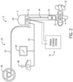
FIG. 2 is a schematic of another exemplary electric marine propulsion system in accordance with the present disclosure. -
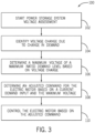
FIGS. 3 is a flow chart depicting an exemplary method of controlling an electric marine propulsion system in accordance with the present disclosure. -
FIGS. 4-5 are control routine flowcharts illustrating an exemplary calculation procedure for determining an adapted system resistance and a minimum voltage. -
FIG. 6 is a graphical illustration of exemplary motor output parameters at various input voltages and minimum voltage values. - The present inventors have recognized that electric marine propulsion poses additional challenges as compared with electric propulsion for land vehicles. One such challenge is the demand for electric marine propulsion systems with removable and interchangeable power storage systems, such as battery systems. Due to range issues and the time it takes to recharge a battery, there is a demand for electric drives that operate with a removable battery, where a vessel operator can have multiple batteries on board at a given time and swap to a new battery once a first battery is drained. Furthermore, marine environments are harsh and can cause damage to batteries, such as due to water exposure, and thus users may carry backup batteries in case of battery damage or failure of the first battery. Vessel owners may have multiple batteries in their fleet, some of which may not be by the original equipment manufacturer (OEM) of the marine drive. Thus, the propulsion control system may not be able to communicate with the power storage system, or a controller therefor, to obtain information about the battery state of health or charge level. The present inventors have recognized challenges arising in the instances where non-OEM batteries are used in place of OEM batteries in an electric marine propulsion system. When a non-OEM battery is connected to an electric marine propulsion system, the system is unable to communicate with the non-OEM battery in the way the that it does with an OEM battery. The resulting effect is that the parameters and specifications of the non-OEM battery are unknown to the propulsion control system, leading to an inability to properly regulate the marine drive and ensure operation of the drive within its capabilities.
- Additionally, an OEM battery may lose communication functions, either due to a failure of the communication link, a controller malfunction, etc. Given that battery voltage changes as a battery is depleted and/or due to changes in the battery's state of health, loss of communication with the power storage system may also result in improper or inconsistent motor control or output.
- The inventors have recognized that propulsion control systems need a way to account for the voltage drop across a power storage system, including the connection elements between the propulsion system and the power storage system. Ascertaining the voltage drop is important because the power producing capacity of the motor changes as a function of input voltage. Thus, accounting for the voltage drop is important for appropriately effectuating a user's propulsion command, as well as for controlling the current delivery to the motor so as to remain within the motor specifications. Accordingly, the inventors developed the disclosed systems and methods which recognize voltage changes at the input of an electric motor to determine and implement a maximum output, prevent overcurrent events, and ensure a smooth derate as the voltage changes and the battery depletes.
- Based on recognition of the foregoing problems and challenges in the relevant art, the inventors developed the disclosed system and method of controlling an electric marine propulsion system to enable the marine vessel to recognize changes in voltage as a result of changes in user demand and adapt the system to perform according to those readings when the system is being powered by one or more non-OEM batteries or one or more OEM batteries that have lost their ability to communicate with the system. The disclosed system and method are configured to facilitate the monitoring of a demand level of the user and inputs to the motor of the electric marine propulsion system and determine the maximum output the motor can produce at a rated torque.
- In one embodiment, the control system may calculate an adapted system resistance and determine the maximum output the motor can produce at the rated torque after recognizing a change in the demand level of the user and measuring the change in demand level and a change in motor input voltage at each demand level. In various embodiments, the maximum output may be effectuated as a minimum voltage, a maximum motor torque, a maximum motor speed (RPM), a maximum motor current or motor power consumed by one or more electric motors in the propulsion system, a maximum demand instruction permitted, a maximum vessel speed, or the like. In various embodiments, the output limit may be automatically effectuated by the control system on the marine vessel such that each marine drive is controlled so as not to exceed the output limit.
- For example, the one or more electric motors, or the power delivered thereto, may be limited by the control system to ensure the marine vessel undergoes a steady derate process as the power in the battery depletes, make sure the motor does not output more than its rated torque, and calibrate the system to adjust current flow as voltage fluctuates. For example, a user may increase the demand level at the helm by 10%. The system may be configured to measure an input voltage to the motor before and after the change, calculate the adapted system resistance from the input voltage and change in demand level, and use the adapted system resistance to determine the minimum voltage the motor would use at its rated torque. From the minimum voltage, the system can then calculate a maximum torque the motor should produce and constrain the system accordingly. The control system may also be configured to store a lookup table or command table and determine the maximum torque by identifying the torque value in the table corresponding to the determined minimum voltage. The system may also be configured to store recently calculated values, such as adapted system resistance, and assign weight to selected values to further smooth the derate process.
-
FIG. 1 depicts an exemplary embodiment of amarine vessel 1 having an electricmarine propulsion system 2 configured to propel the marine vessel. Referring also toFIG. 2 , theelectric propulsion system 2 includes at least one electricmarine drive 3 having anelectric motor 4 configured to propel themarine vessel 1 by rotating apropeller 10, as well as apower storage system 16, and auser interface system 35. In the depicted embodiment ofFIG. 2 , the electricmarine propulsion system 2 includes an outboardmarine drive 3 having anelectric motor 4 housed therein, such as housed within thecowl 50 of the outboard marine drive. A person of ordinary skill in the art will understand in view of the present disclosure that themarine propulsion system 2 may include other types of electric marine drives 3, such as inboard drives or stern drives. The electricmarine drive 3 is powered by thescalable storage device 16. - The electric
marine propulsion system 2 may include one or a plurality of electric marine drives 3, each comprising at least oneelectric motor 4 configured to rotate a propulsor, orpropeller 10. Themotor 4 may be, for example, a brushless electric motor, such as a brushless DC motor. In other embodiments, the electric motor may be a DC brushed motor, an AC brushless motor, a direct drive, a permanent magnet synchronous motor, an induction motor, or any other device that converts electric power to rotational motion. In certain embodiments, theelectric motor 4 includes a rotor and a stator in a known configuration. - The
electric motor 4 is electrically connected to and powered by apower storage system 16. Thepower storage system 16 stores energy for powering theelectric motor 4. Various power storage devices and systems are known in the relevant art. Thepower storage system 16 may be a battery system configured to receive one or more batteries or banks of batteries of different varieties including OEM batteries, third party batteries, or both. For example, thepower storage system 16 may include one or more lithium-ion (LI) battery systems, each LI battery comprised of multiple battery cells. In other embodiments, thepower storage system 16 may include one or more lead-acid batteries, fuel cells, flow batteries, ultracapacitors, and/or other devices capable of storing and outputting electric energy. - The
electric motor 4 is operably connected to thepropeller 10 and configured to rotate thepropeller 10. As will be known to the ordinary skilled person in the relevant art, thepropeller 10 may include one or more propellers, impellers, or other propulsor devices and that the term "propeller" may be used to refer to all such devices. In certain embodiments, such as that represented inFIG. 1 , theelectric motor 4 may be connected and configured to rotate thepropeller 10 through agear system 7 or a transmission. In such an embodiment, thegear system 7 translates rotation of themotor output shaft 5 to thepropeller shaft 8 to adjust conversion of the rotation and/or to disconnect thepropeller shaft 8 from thedrive shaft 5, as is sometimes referred to in the art as a "neutral" position where rotation of thedrive shaft 5 is not translated to thepropeller shaft 8.Various gear systems 7, or transmissions, are well known in the relevant art. In other embodiments, theelectric motor 4 may directly connect to thepropeller shaft 8 such that rotation of thedrive shaft 5 is directly transmitted to thepropeller shaft 8 at a constant and fixed ratio. - A
control system 11 controls the electricmarine propulsion system 2, wherein thecontrol system 11 may include a plurality of control devices configured to cooperate to provide the method of controlling the electric marine propulsion system described herein. For example, thecontrol system 11 may include acentral controller 12, and one or more motor controllers, trim controllers, steering controllers, etc. communicatively connected, such as by a communication bus or other communication link. A person of ordinary skill in the art will understand in view of the present disclosure that other control arrangements could be implemented and are within the scope of the present disclosure, and that the control functions described herein may be combined into a single controller or divided into any number of a plurality of distributed controllers that are communicatively connected. - Each controller may comprise a processor and a storage device, or memory, configured to store software and/or data utilized for controlling and/or tracking operation of the
electric propulsion system 2. The memory may include volatile and/or non-volatile systems and may include removable and/or non-removable media implemented in any method or technology for storing of information. The storage media may include non-transitory and/or transitory storage media, including random access memory, read only memory, or any other medium which can be used to store information and be accessed by an instruction execution system, for example. Such information may include a command table containing a set of adjustment commands based on measured or calculated values. An input/output (I/O) system facilitates communication between thecontrol system 11 and connected devices. - Each
electric motor 4 may be associated with amotor controller 14 configured to control power to the electric motor, such as to the stator winding thereof. Themotor controller 14 is configured to control the function and output of theelectric motor 4, such as controlling the torque outputted by themotor 4, the rotational speed of themotor 4, as well as the input current, voltage, and power supplied to and utilized by themotor 4. In one arrangement, themotor controller 14 controls the current delivered to the stator windings via theleads 15, which input electrical energy to the electric motor to induce and control rotation of the rotor. - In certain embodiments,
various sensing devices motor controller 14 orpower controller 62, and in other embodiments thesensors central controller 12 and themotor controller 14 may be eliminated. AGPS system 56 may also be configured to determine a current global position of the vessel, track vessel position over time, and/or determine vessel speed and direction of travel, and to provide such information to thecontroller 12. Alternatively or additionally, vessel speed may be measured by a speed-over-water sensor such as a pitot tube or a paddle wheel and such information may be provided to thecontroller 12.Controllers 12 and 14 (and or the various sensors and systems) may be configured to communicate via acommon communication link 34 such as a CAN bus (e.g., a CAN Kingdom Network) or a LIN bus, or by single dedicated communication links betweencontrollers - Sensors may be configured to sense the power, including the current and voltage, delivered to the
motor 4 and/or voltage sensed at other locations within the system. For example, a plurality ofvoltage sensors Voltage sensor 29 may be configured to sense the input voltage to themotor 4 and acurrent sensor 28 may be configured to measure input current to themotor 4. Accordingly, power delivered to themotor 4 can be calculated and such value can be used for monitoring and controlling theelectric propulsion system 2, including for monitoring and controlling themotor 4 and ensuring thesystem 2 is operating within the capabilities of theelectric motor 4. Alternatively or additionally, thesystem 2 may include avoltage sensor 39 at or near the connection point of the vessel system(s) to thepower storage system 16 to sense the voltage at the location(s) of power input. Alternatively or additionally, avoltage sensor 49, or multiple voltage sensors, may be located to measure voltage powering one or moreauxiliary devices 60. In certain embodiments, thevoltage sensor 49 may comprise part of thepower controller 62 for the auxiliary power system and/or may be configured to measure voltage at one or more converters, such as a DC-DC converter powering auxiliary electronics or other auxiliary devices. - In the depicted example, the
current sensor 28 andvoltage sensor 29 may be communicatively connected to themotor controller 14 to provide measurement of the voltage supplied to the motor and current supplied to the motor. Other voltage sensor(s) 39, 49 may be configured to provide voltage measurement outputs to thecontroller 12 and/or themotor controller 14. Themotor controller 14 is configured to provide appropriate current and or voltage to meet the demand for controlling themotor 4. For example, a demand input may be received at themotor controller 14 from thecentral controller 12, such as based on an operator demand at a helm input device, such as thethrottle lever 38. In certain embodiments, themotor controller 14,voltage sensor 28, andcurrent sensor 29 may be integrated into a housing of theelectric motor 4, and in other embodiments themotor controller 14 may be separately housed. - Various other sensors may be configured to measure and report parameters of the
electric motor 4. For example, theelectric motor 4 may include means for measuring and or determining the torque, rotation speed (motor speed), current, voltage, temperature, vibration, or any other parameter. In the depicted example, theelectric motor 4 includes aspeed sensor 24 configured to measure a rotational speed of the motor 4 (motor RPM). Alternatively or additionally,propeller speed sensor 26 may be configured to measure a rotational speed of thepropeller 10. For example, thepropeller speed sensor 26 and/or themotor speed sensor 24 may be a Hall Effect sensor or other rotation sensor, such as using capacitive or inductive measuring techniques. In certain embodiments, one or more of the parameters, such as the speed, torque, or power to theelectric motor 4, may be calculated based on other measured parameters or characteristics. For example, the torque may be calculated based on power characteristics in relation to the rotation speed of the electric motor, for example. - The
central controller 12, which in the embodiment shown inFIG. 2 is a propulsion control module (PCM), communicates with themotor controller 14 viacommunication link 34, such as a CAN bus. The controller also receives input from and/or communicates with one or more user interface devices in theuser interface system 35 via the communication link, which in some embodiments may be the same communication link as utilized for communication between thecontrollers throttle lever 38 and adisplay 40. In various embodiments, thedisplay 40 may be, for example, part of an onboard management system, such as the VesselView™ by Mercury Marine of Fond du Lac, Wisconsin. Asteering wheel 36 is provided, which in some embodiments may communicate with thecontroller 12 or other control device in thecontrol system 11 to effectuate steering control over themarine drive 3, which is well-known and typically referred to as a steer-by-wire arrangement. Alternatively, as in the depicted embodiment, thesteering wheel 36 is a wired steering arrangement where thesteering wheel 36 is connected to a steering actuator that steers themarine drive 3 by asteering cable 37. Other steering arrangements, such as various wired and steer-by-wire arrangements, are well-known in the art and could alternatively be implemented. - The various parameters of the electric propulsion system are utilized for providing user-controlled or automatically effectuated vessel power control functionality appropriate for optimizing power usage. The system may be configured to control power usage by the
electric propulsion system 2, for example so that power available and utilized to effectuate propulsion remains within calculated limits to provide consistent propulsion and operate the motors within the rated operation parameters. The system may be configured to operate in a variety of userselectable power modes, or in various power modes that may be automatically selected by thecontrol system 11 based on sensed parameters and/or operating conditions of thepropulsion system 2. - The
power storage system 16 may further be configured to powerauxiliary devices 60 on themarine vessel 1 that are not part of thepropulsion system 2. For example, the auxiliary devices may include a bilge pump, cabin lights, a stereo system or other entertainment devices on the vessel, a water heater, a refrigerator, an air conditioner or other climate/comfort control devices on the vessel, communication systems, navigation systems, or the like. Some or all these accessory devices are sometimes referred to as a "house load" and may consume a substantial amount of battery power. Additionally, other non-motor loads may be powered by thepower storage system 16, such as steering, motor trim, trim tabs, and other devices relating to steering and/or vessel orientation control. - The power consumption by some or all of the auxiliary devices and/or non-motor loads may be monitored and/or controllable, such as by a
power controller 62 associated with each controlled auxiliary device or a group of auxiliary devices (FIG. 1 ). Thepower controller 62 is communicatively connected to thecontroller 12 or is otherwise communicating with one or more controllers in thecontrol system 11, in order to monitor and/or control power consumption by such auxiliary devices. For example, thepower controller 62 may be configured to communicate with one or more power monitoring or other control devices via CAN bus or LIN bus, and to then control operation of the auxiliary device and/or power delivery to the auxiliary device according to received instructions. For instance, the system may be configured to reduce power delivery or prevent change in power deliver to the device(s) 60 during certain measurement periods, or to selectively turn off the auxiliary device(s) 60 by turning on or off power delivery to the device(s) 60 associated with thepower controller 62 during the measurement period. For example, thepower controller 62 for one or a set of auxiliary devices may include a battery switch controlling power thereto. Thecontrol system 11 may thus include digital switching system configured to control power to the various auxiliary devices, such as a CZone Control and Monitoring system by Power Products, LLC of Menomonee Falls, WI. Other examples of power control arrangements are further exemplified and described atUS Application Nos. 17/009,412 16/923,866 - The
control system 11 may be configured to receive a plurality of sensor data from the sensors. Such sensor data may include input voltage to theelectric motor 4, input current to theelectric motor 4, motor RPM, marine vessel speed, etc. The control system 22 is then configured to determine one or more parameters relating to thepower storage system 16 when such values are not communicated from the power storage system, such as due to a lack of communication from a battery control system, and to operate thepropulsion system 2 accordingly.FIG. 3 depicts anexemplary method 100 of controlling an electric marine propulsion system to determine and account for a voltage drop across a power storage system. The power storage system voltage assessment is initiated atstep 102, such as based on an initiation instruction. For example, the initiation instruction may be provided upon key up of thepropulsion system 2, where the voltage monitoring runs continually during operation of thepropulsion system 2, and/or may be provided periodically such that the voltage status of thepower storage system 16 is monitored and accounted for throughout the operation period. - The memory of the
central controller 12 is operable to store the plurality of sensor data (e.g., fromsensors electric motor 4 has been running, turning on or off thepropulsion system 2, or a threshold change in demand level. Thecontrol system 11 can read the data received and compare it to previously received sensor data, stored in the memory, to determine whether there has been a change in demand level. A threshold value may be assigned, where a recently received plurality of sensor data must differ from a previously received plurality of sensor data by a value greater than or equal to the threshold value for the electricmarine propulsion system 2 to recognize that the demand level has changed. In other embodiments, the sensor data must be greater than the previously received plurality of sensor data. A variety of methods may be used to determine a threshold value, including a sensor resolution of the sensors or noise level of the input voltage measurement. - Step 104 is executed to determine a voltage change due to a change in demand level. For example, the system may be configured to identify a change in demand level of the electric motor and to determine a voltage change associated with the change in demand level. The
control system 11 may also be configured to perform a plurality of calculations upon the system recognizing that a change in demand level has occurred. In various embodiments, the change in demand level may be determined based on a change in demand percent (e.g., based on a change in helm command), a change in motor RPM, a change in motor current, or a change in measured or calculated motor torque. To avoid the impacts of transient changes and/or sensor error, the control system may be configured to detect the change in demand level based on steady state demand values, such as detecting the occurrence of at least a threshold change in demand levels. - Where the voltage is being measured at the connection to the
power storage system 15, thecontrol system 11 may also be configured to make sure that other changes in power demand from non-motor sources did not occur that would materially impact the system voltage draw and thus introduce material inaccuracies into the motor voltage calculation. For example, thecontrol system 11 may be configured to identify the threshold change in demand level only during periods of static auxiliary load, such as when the change in auxiliary load is less than a threshold. Alternatively, thesystem 11 may be configured to exert some control over auxiliary load during the short period where the demand change is being measured, which for example may be over a period of a few seconds, such as to prevent large load devices from turning on or off during the measurement period. - For example, the
control system 11 may be configured to identify a first steady state torque and a second steady state torque, the difference of which is delta torque representative of a change in demand level requested by the user or requested by a navigation controller generating a demand based on an autonomous control algorithm (such as a station keeping, waypoint navigation, or autonomous docking or launch control algorithm). Thecontrol system 11 may also measure a first motor DC input voltage at the first steady state torque and a second motor DC input voltage at the second steady state torque. The first and second steady state torques are measures of the demand level of the system when the system is relatively stable and a transient state has settled. For example, the torque (or other demand value) may be determined as steady state when the value changes by less than a threshold amount over a predetermined period, such as a threshold amount that accounts for noise, sensor error, etc. within the system. - The
control system 11 may use the plurality of sensor data and information or instructions stored in the memory to determine a plurality of system values in addition to the voltage change across thepower storage system 16 or at themotor 4, including to determine an adapted system resistance. The adapted system resistance may represent an internal resistance of at least one battery in thepower storage system 16 and a resistance of connection elements connecting theelectric motor 4 to the battery or other power storage device(s). - The voltage change may further be used to determine a minimum voltage at a maximum rated demand level for the
electric motor 4 as represented atstep 106. The maximum rated demand level may be a maximum rated torque, or may be a different value representative of demand as described above. Calculation of the minimum voltage informs the system of a new minimum voltage at an instant in time of the demand change, such as if the operator requested a maximum demand level at thehelm input device 38. For example, the minimum voltage may be calculated based on the adapted system resistance. - The
control system 11 may be configured to use the minimum voltage to determine an adjusted command, represented atstep 108. The adjusted command may be, for example, a torque command, a speed command, a commanded current, or other value for controlling motor operation and output. By continuously monitoring demand level and determining new adjusted commands, a loss of propulsion of the electricmarine propulsion system 2 can be smoothed as thepower storage system 16 is depleted. Adjusted commands may be determined by looking up values from the command tables corresponding to input values or the calculated minimum voltage. The adjusted motor command is communicated to themotor 4, such as from thePCM 12 to themotor controller 14, such that themotor 4 is operated atstep 110 within the determined minimum voltage constraint. - The adjusted command may be determined and implemented by various methods. For example, a demand level ceiling may be adjusted, such as adjusting a maximum demand value and capping the user command authority so as not to exceed the maximum demand value. Where the adjusted command is implemented as a change in the maximum permitted demand, the demand values associated with each helm command-e.g., throttle lever position-remain unchanged, and a ceiling is placed at the new maximum demand value (e.g., the maximum torque) such that the torque will cease to increase when the
throttle lever 38 is pushed past the position associated with the new maximum demand value. Alternatively, the adjusted command may be determined by recalculating, or remapping, the demand level value associated with a given helm command at a user input device. In such an embodiment, thecontrol system 11 may adjust the output values that correspond with each helm command value, such as each throttle lever position, such that the maximum torque at the maximum rated demand level may always be achieved when thethrottle lever 38 is pushed all the way forward to its maximum position. The maximum torque (or other maximum demand value) is associated with a maximum throttle lever position and all other throttle lever positions are remapped accordingly. - The control diagram at
FIG. 4 illustrates an exemplary control routine 190 executed by thecontrol system 11 for determining an adapted system resistance as part of an exemplary embodiment of themethod 100 for controlling thepropulsion system 2. A firststeady state torque 191, a first motorDC input voltage 193 at the firststeady state torque 191, a secondsteady state torque 192, and a second motorDC input voltage 194 at the secondsteady state torque 192 are received as inputs to the control method. Motor constant (kt) 197 is also an input. The firststeady state torque 191 indicates a torque of theelectric motor 4 at a first steady state demand level of the user, and the secondsteady state torque 192 indicates the torque of theelectric motor 4 after the demand level of the user increases or decreases to a second steady state demand level. The first motorDC input voltage 193 and second motorDC input voltage 194 indicate the voltage drop across theelectric motor 4 when the torque of themotor 4 is equal to the firststeady state torque 191 or the secondsteady state torque 192, respectively. TheDC input voltages voltage sensor 29 at the motor. Alternatively, voltage measurements from elsewhere in the system may be utilized, such as fromvoltage sensors 39 and/or 49 and logic may be executed to verify that a material change in demand from a non-motor element did not occur that would materially impact the calculations. For example, the threshold change in torque may be identified only during periods of relatively static auxiliary load, such as when the change in auxiliary load is less than a threshold. Themotor constant 197 indicates how much torque a motor will produce for a given current. The control algorithm utilizes a series of calculations and unit conversions to determine the adaptedsystem resistance 199 from theinputs steady state torque 191 and the secondsteady state torque 192, which are exemplary demand values, may instead be steady state current values, speed values (e.g., motor RPM), or the like with logic of the control routine flow diagram changing accordingly to account for the differing input units. -
Calculation function 186 is executed to determine adelta torque 195 which represents a change in the demand level of a user.Calculation function 187 is executed to determine avoltage change 196 representing a change in input voltage to the motor in response to the change in the demand level.Calculation function 188 is executed to determine a voltage change per demand increment 198-e.g., the voltage change per newton meter (Nm) of torque.Calculation function 189 is then executed to determine the adaptedsystem resistance 199 of the electricmarine propulsion system 2. The system resistance value includes the resistance of thepower storage system 16, including the internal resistance of the one or more batteries therein, any resistance of the connection hardware, etc. - Each subsequent adapted system resistance calculation may be stored in the memory of the
control system 11 for a designated period of time such as a length of a trip. Thecontrol system 11 may be configured to determine a filtered adapted system resistance based on the adapted system resistance calculations over time. Methods for determining the filtered adapted system resistance may include averaging a current adapted system resistance with the previous adapted system resistances, which may be a weighted average to give the current adaptive system resistance more weight, or worth, in the filtered calculation. Calculating and using the filtered adapted system resistance may be advantageous for providing a smooth and consistent derate as voltage of the system decreases. - The control diagram at
FIG. 5 illustrates a secondexemplary control routine 200 for calculating a minimum voltage at a maximum rated demand as part of an exemplary embodiment of themethod 100 of controlling thepropulsion system 2. Following on the exemplary adapted system resistance calculation illustrated inFIG. 4 , the demand value here is torque. However, the example may be adapted based on other demand values, as described above, and a person of ordinary skill in the art will understand in view of the present disclosure how to adapt the calculations to accommodate other demand values, such as motor current or motor RPM. - The rated
torque 201 of theelectric motor 4 and thecurrent torque 192 are received as inputs to thecontrol routine 200. The adaptedsystem resistance 199, motor constant (kt) 197, the current torque 192 (the steady state torque after the change in demand level), and the current motor input voltage 194 (the motor voltage at the second steady state demand level) are also inputs, which are values determined as part of the first control routine described above. The ratedtorque 201 indicates the highest torque themotor 4 is rated to provide-e.g., the highest torque output that the motor is capable of under normal operating conditions.Calculation function 207 is executed to determine a torque offset 203, which represents a difference in torque between the ratedtorque 201 and thecurrent torque 192. Atcalculation function 208, the adaptedsystem resistance 199 is utilized, along with the torque offset 203, to calculate a demand timesresistance value 204.Function 209 is executed to determine avoltage change 205 based on themotor constant 197 and thecalculated value 204. Thevoltage change 205 thus represents the difference in voltage between the current voltage value and the voltage at the maximum rated demand value, which here is the ratedtorque 201.Function 210 is then executed to determine theminimum voltage 206 based on thevoltage change 205 and thecurrent motor voltage 194. Theminimum voltage 206 indicates a motor voltage for the rated torque 201 (or other demand value) at an instant in time if a maximum rated demand level were to be requested by the user. Determining theminimum motor voltage 206 allows the controller to determine a maximum output themotor 4 can provide and to regulate themotor 4 in a way that keeps it operating within its capabilities and in a way that gradually derates as the voltage level as the power storage system depletes. - To demonstrate the above process of determining a maximum voltage, the following example is provided according to
FIGS. 4-5 . In the example, the user is operating themarine vessel 1 which is being powered by non-OEM batteries in thepower storage system 16. In this example the motor constant (kt) 197 is
torque 201, or the highest torque the motor is normally capable of, is 100 Nm. The user is currently commanding a firststeady state torque 191 of 80 Nm from themotor 4, and, in this example, at a demand level of 80 Nm, thefirst input voltage 193 at themotor 4 is 48 V. The user decided to increase the demand level and pushed the throttle lever forward to request a secondsteady state torque 192 of 88 Nm from themotor 4. In this example, at a demand level of 88 Nm, thesecond input voltage 194 at themotor 4 is 40 V. Thecontrol system 11 is configured to calculate thedelta torque 195 to be -8 Nm and thefirst voltage change 196 at themotor 4 to be -8 V. The system then divides thefirst voltage change 196 by thedelta torque 195 to get
system resistance 199 of
system resistance 199 to find theminimum voltage 206 themotor 4 can utilize at that instant in time if the user requested 100% demand. Thecontrol system 11 starts by finding the offset 203 in torque between what themotor 4 is rated for and what is currently being demanded: 100 Nm - 88 Nm = 12 Nm. The torque offset 203 is multiplied by the adaptedsystem resistance 199 and divided by the motor constant 197 to determine a second voltage change 205:
second voltage change 205 is then subtracted from thecurrent motor voltage 194 to determine theminimum voltage 206 themotor 4 can handle at the rated torque 201: 48 V - 12 V = 36 V. Theminimum voltage 206 can then be used to determine an adjusted command. -
FIG. 6 is agraph 310 illustrating the output that an exemplary motor is capable of producing at exemplary voltage levels, represented bylines graph 310 demonstrates that at higher input voltages, the motor is capable of outputting greater torque and reaching higher motor speeds than at lower input voltages. As the voltage decreases, the motor loses its ability to produce the highest output levels, so the derate process must begin. The control system is operable to calculate theminimum voltage 206 at the motor, and based on theminimum voltage 206 determine the maximum demand level (e.g., torque) themotor 4 can handle and limit the system accordingly. By adapting to changes in voltage, thecontrol system 11 ensures thepropulsion system 2 is always operating within the capability of the motor and implements a consistent derate as voltage of thepower storage system 16 drops or changes with different batteries and power storage arrangements that may be utilized. -
FIG. 6 shows exemplary minimum voltages as dashedlines controller 12 may store a command table consisting of adjusted command values based on minimum voltage values, such as maximum torque values associated with each of a range of minimum voltage values. Once theminimum voltage 206 is determined, the controller may utilize the command table to look up the corresponding maximum torque and adjust the command to the motor accordingly. In various embodiments, the command adjustment may be implemented by remapping the user input commands at the helm such that the maximum torque is associated with the 100% helm command level (e.g., full throttle) and everything below is adjusted accordingly. In other embodiments, the maximum demand value and corresponding command adjustment may be implemented via a dead band, where thecontrol system 11 sets a torque ceiling such that the output of the motor will only increase until the point of the maximum torque and any user commands for output above the maximum torque will not be effectuated. - This written description uses examples to disclose the invention, including the best mode, and also to enable any person skilled in the art to make and use the invention. Certain terms have been used for brevity, clarity and understanding. No unnecessary limitations are to be inferred therefrom beyond the requirement of the prior art because such terms are used for descriptive purposes only and are intended to be broadly construed. The patentable scope of the invention is defined by the claims, and may include other examples that occur to those skilled in the art. Such other examples are intended to be within the scope of the claims if they have features or structural elements that do not differ from the literal language of the claims, or if they include equivalent features or structural elements with insubstantial differences from the literal languages of the claims.
- The following numbered embodiments are also provided:
- 1. An electric marine propulsion system configured to propel a marine vessel, the system comprising:
- at least one electric motor powered by a power storage system and configured to rotate a propulsor to propel the marine vessel;
- a control system configured to:
- determine a voltage change due to a change in demand level of the electric motor;
- determine a minimum voltage at a maximum rated demand level for the electric motor based on the voltage change;
- determine an adjusted command for the electric motor based on the minimum voltage and a current demand input; and
- control the electric motor based on the adjusted command.
- 2. The system of
embodiment 1, wherein the control system is further configured to determine an adapted system resistance based on the voltage change, and wherein the minimum voltage is determined based on the adapted system resistance. - 3. The system of
embodiment 2, wherein the adapted system resistance includes an internal resistance of at least one battery in the power storage system and a resistance of connection elements connecting the electric motor to the at least one battery. - 4. The system of
embodiment - 5. The system of
embodiment - identify the change in demand level that is at least a threshold change;
- identify the voltage change as a corresponding change in input voltage at the electric motor that corresponds with the threshold change in demand level; and
- determine the adapted system resistance based on the change in demand level and the corresponding change in input voltage.
- 6. The system of any one of embodiments 1-5, wherein the change in demand level is one of a threshold change in motor current, a threshold change in motor torque, and a threshold change in helm command.
- 7. The system of any one of embodiments 1-6, wherein the control system is further configured to:
- identify a first steady state demand level and measure a first motor input voltage at the first steady state demand level;
- identify a second steady state demand level and measure a second motor input voltage at the second steady state demand level;
- wherein the change in demand level is a difference between the first steady state demand level and the second steady state demand level.
- 8. The system of any one of embodiments 1-7, wherein the maximum rated demand level is a maximum rated torque for the electric motor, wherein the current demand input is a current torque demand, and the adjusted command is a torque command to the electric motor.
- 9. The system of any one of embodiments 1-8, wherein the current demand input (e.g. current torque demand) is based on a user demand input at a user input device.
- 10. The system of embodiment 9, wherein the control system is further configured to rescale user demand input values from the user input device based on the minimum voltage.
- 11. The system of any one of embodiments 1-10, wherein the control system is further configured to limit user authority over output of the electric motor based on the minimum voltage.
- 12. The system of any one of embodiments 1-11, further comprising a command table stored in memory comprising adjusted command values based on minimum voltage values;
wherein the control system is further configured to access the command table based on the minimum voltage and the current demand input to determine the adjusted command. - 13. A method of controlling an electric marine propulsion system comprising at least one electric motor powered by a power storage system and configured to rotate a propulsor to propel a marine vessel, the method comprising:
- determining a voltage change due to a change in demand level of the electric motor;
- determining a minimum voltage at a maximum rated demand level for the electric motor based on the voltage change;
- determining an adjusted command for the electric motor based on the minimum voltage and a current demand input; and
- controlling the electric motor based on the adjusted command.
- 14. The method of embodiment 13, further comprising determining an adapted system resistance based on the voltage change, wherein the minimum voltage is determined based on the adapted system resistance.
- 15. The method of
embodiment 14, wherein the adapted system resistance includes an internal resistance of at least one battery in the power storage system and a resistance of connection elements connecting the electric motor to the power storage system. - 16. The method of
embodiment - 17. The method of
embodiment - identifying the change in demand level that is at least a threshold change;
- identifying a corresponding change in input voltage at the motor that corresponds with the threshold change in demand level; and
- determining the adapted system resistance based on the change in demand level and the corresponding change in input voltage.
- 18. The method of any one of embodiments 13-17, wherein the change in demand level is one of a threshold change in motor current, a threshold change in motor torque, and a threshold change in helm command.
- 19. The method of any one of embodiments 13-18, further comprising:
- identifying a first steady state demand level and measure a first motor input voltage at the first steady state demand level;
- identifying a second steady state demand level and measure a second motor input voltage at the second steady state demand level;
- wherein the change in demand level is a difference between the first steady state demand level and the second steady state demand level.
- 20. The method of any one of embodiments 13-19, wherein the maximum rated demand level is a maximum rated torque for the electric motor, wherein the current demand input is a current torque demand, and the adjusted command is a torque command to the electric motor.
- 21. The method of any one of embodiments 13-20, wherein the current demand input (e.g. current torque demand) is based on a user demand input at a user input device.
- 22. The method of embodiment 21, further comprising rescaling user demand input values from the user input device based on the minimum voltage.
- 23. The method of any one of embodiments 13-22, further comprising limiting user authority over output of the electric motor based on the minimum voltage.
- 24. The method of any one of embodiments 13-23, further comprising accessing a command table based on the minimum voltage and the current demand input to determine the adjusted command, wherein the command table comprises adjusted command values based on minimum voltage values.
Claims (15)
- An electric marine propulsion system (2) configured to propel a marine vessel (1), the system (2) comprising:at least one electric motor (4) powered by a power storage system (16) and configured to rotate a propulsor (10) to propel the marine vessel (1);a control system (11) configured to:determine a voltage change (196) due to a change in demand level of the electric motor (4);determine a minimum voltage (206) at a maximum rated demand level for the electric motor (4) based on the voltage change (196);determine an adjusted command for the electric motor (4) based on the minimum voltage (206) and a current demand input; andcontrol the electric motor (4) based on the adjusted command.
- The system (2) of claim 1, wherein the control system (11) is further configured to determine an adapted system resistance (199) based on the voltage change (196), and wherein the minimum voltage (206) is determined based on the adapted system resistance (199).
- The system (2) of claim 2, wherein the adapted system resistance (199) includes an internal resistance of at least one battery in the power storage system (16) and a resistance of connection elements connecting the electric motor (4) to the at least one battery.
- The system (2) of claim 2 or 3, wherein the control system (11) is further configured to determine a filtered adapted system resistance based on the adapted system resistance (199) over time, and wherein the minimum voltage (206) is determined based on the filtered adapted system resistance.
- The system (2) of claim 2, 3 or 4, wherein the control system (11) is further configured to:identify the change in demand level that is at least a threshold change;identify the voltage change (196) as a corresponding change in input voltage at the electric motor (4) that corresponds with the threshold change in demand level; anddetermine the adapted system resistance (199) based on the change in demand level and the corresponding change in input voltage.
- The system (2) of any one of claims 1-5, wherein the change in demand level is one of a threshold change in motor current, a threshold change in motor torque, and a threshold change in helm command.
- The system (2) of any one of claims 1-6, wherein the control system (11) is further configured to:identify a first steady state demand level and measure a first motor input voltage (193) at the first steady state demand level;identify a second steady state demand level and measure a second motor input voltage (194) at the second steady state demand level;wherein the change in demand level is a difference between the first steady state demand level and the second steady state demand level.
- The system (2) of any one of claims 1-7, wherein the maximum rated demand level is a maximum rated torque (201) for the electric motor (4), wherein the current demand input is a current torque demand (192), and the adjusted command is a torque command to the electric motor (4).
- The system (2) of any one of claims 1-8, wherein the current demand input is based on a user demand input at a user input device (38).
- The system (2) of claim 9, wherein the control system (11) is further configured to rescale user demand input values from the user input device (38) based on the minimum voltage (206).
- The system (2) of any one of claims 1-10, wherein the control system (11) is further configured to limit user authority over output of the electric motor (4) based on the minimum voltage (206).
- The system (2) of any one of claims 1-11, further comprising a command table stored in memory comprising adjusted command values based on minimum voltage values;
wherein the control system (11) is further configured to access the command table based on the minimum voltage (206) and the current demand input to determine the adjusted command. - A method of controlling an electric marine propulsion system (2) comprising at least one electric motor (4) powered by a power storage system (16) and configured to rotate a propulsor (10) to propel a marine vessel (1), the method comprising:determining a voltage change (196) due to a change in demand level of the electric motor (4);determining a minimum voltage (206) at a maximum rated demand level for the electric motor (4) based on the voltage change (196);determining an adjusted command for the electric motor (4) based on the minimum voltage (206) and a current demand input; andcontrolling the electric motor (4) based on the adjusted command.
- The method of claim 13, further comprising determining an adapted system resistance (199) based on the voltage change (196), wherein the minimum voltage (206) is determined based on the adapted system resistance (199).
- The method of claim 14, wherein the adapted system resistance (199) includes an internal resistance of at least one battery in the power storage system (16) and a resistance of connection elements connecting the electric motor (4) to the power storage system (16).
Applications Claiming Priority (1)
| Application Number | Priority Date | Filing Date | Title |
|---|---|---|---|
| US17/892,882 US20240059386A1 (en) | 2022-08-22 | 2022-08-22 | Electric marine propulsion system and control method with voltage adaptation |
Publications (3)
| Publication Number | Publication Date |
|---|---|
| EP4331972A1 true EP4331972A1 (en) | 2024-03-06 |
| EP4331972C0 EP4331972C0 (en) | 2026-02-11 |
| EP4331972B1 EP4331972B1 (en) | 2026-02-11 |
Family
ID=87580298
Family Applications (1)
| Application Number | Title | Priority Date | Filing Date |
|---|---|---|---|
| EP23191674.3A Active EP4331972B1 (en) | 2022-08-22 | 2023-08-16 | Electric marine propulsion system and control method with voltage adaptation |
Country Status (2)
| Country | Link |
|---|---|
| US (1) | US20240059386A1 (en) |
| EP (1) | EP4331972B1 (en) |
Families Citing this family (1)
| Publication number | Priority date | Publication date | Assignee | Title |
|---|---|---|---|---|
| US12227279B2 (en) * | 2022-01-12 | 2025-02-18 | Brunswick Corporation | Electric marine propulsion system and control method |
Citations (5)
| Publication number | Priority date | Publication date | Assignee | Title |
|---|---|---|---|---|
| US6507164B1 (en) | 2001-04-20 | 2003-01-14 | Brunswick Corporation | Current based power management for a trolling motor |
| US6902446B1 (en) | 2003-04-07 | 2005-06-07 | Brunswick Corporation | DC motor with integral controller |
| US7218118B1 (en) | 2004-04-12 | 2007-05-15 | Brunswick Corporation | Method for monitoring a condition of a battery |
| CN110963016A (en) * | 2019-12-30 | 2020-04-07 | 宁波海伯集团有限公司 | A Wide Pressure Input Suspended Thruster |
| US20220194542A1 (en) | 2020-12-22 | 2022-06-23 | Brunswick Corporation | Electric marine propulsion systems and methods of control |
Family Cites Families (13)
| Publication number | Priority date | Publication date | Assignee | Title |
|---|---|---|---|---|
| US7228925B2 (en) * | 2002-10-04 | 2007-06-12 | Tesla Capital, Llc | Electrical systems for electric powered vehicles |
| US20070182350A1 (en) * | 2004-03-05 | 2007-08-09 | In Motion Technologies | Method and apparatus for controlling an electric motor |
| JP4699923B2 (en) * | 2006-03-13 | 2011-06-15 | 株式会社日立産機システム | Induction motor driving apparatus and method |
| US8049358B2 (en) * | 2007-10-15 | 2011-11-01 | Converteam Technology Ltd | Marine power distribution and propulsion systems |
| US8083557B2 (en) * | 2008-01-18 | 2011-12-27 | Steven Sullivan | Method and apparatus for powering of amphibious craft |
| CN102481858B (en) * | 2009-09-01 | 2014-11-05 | 波士顿电力公司 | Safety and performance optimized controls for large scale electric vehicle battery systems |
| NO332138B2 (en) * | 2009-11-09 | 2016-04-11 | Rolls Royce Marine As Power Electric Systems Bergen | Hybrid propulsion system for a vessel |
| DE102011087015B4 (en) * | 2011-11-24 | 2017-11-16 | Airbus Operations Gmbh | Energy supply system, aircraft or spacecraft and procedures |
| CN104685367B (en) * | 2012-11-29 | 2017-09-08 | 株式会社Lg化学 | Apparatus and method for estimating power of secondary battery including mixed cathode material |
| US9988135B2 (en) * | 2016-03-31 | 2018-06-05 | Caterpillar Inc. | System for controlling an electrical power system |
| US10654551B1 (en) * | 2019-02-13 | 2020-05-19 | GM Global Technology Operations LLC | Method of overshoot for faster planing of marine vessel |
| US11616457B2 (en) * | 2020-10-07 | 2023-03-28 | Steering Solutions Ip Holding Corporation | Torque capability optimization under active limiting of regenerative current in synchronous motor drives |
| US20230249795A1 (en) * | 2022-02-08 | 2023-08-10 | Hercules Electric Mobility, Inc. | Integrated electric pontoon drive system |
-
2022
- 2022-08-22 US US17/892,882 patent/US20240059386A1/en active Pending
-
2023
- 2023-08-16 EP EP23191674.3A patent/EP4331972B1/en active Active
Patent Citations (6)
| Publication number | Priority date | Publication date | Assignee | Title |
|---|---|---|---|---|
| US6507164B1 (en) | 2001-04-20 | 2003-01-14 | Brunswick Corporation | Current based power management for a trolling motor |
| US6902446B1 (en) | 2003-04-07 | 2005-06-07 | Brunswick Corporation | DC motor with integral controller |
| US7218118B1 (en) | 2004-04-12 | 2007-05-15 | Brunswick Corporation | Method for monitoring a condition of a battery |
| CN110963016A (en) * | 2019-12-30 | 2020-04-07 | 宁波海伯集团有限公司 | A Wide Pressure Input Suspended Thruster |
| US20220194542A1 (en) | 2020-12-22 | 2022-06-23 | Brunswick Corporation | Electric marine propulsion systems and methods of control |
| EP4019394A1 (en) * | 2020-12-22 | 2022-06-29 | Brunswick Corporation | Electric marine propulsion systems and methods of control |
Also Published As
| Publication number | Publication date |
|---|---|
| EP4331972C0 (en) | 2026-02-11 |
| US20240059386A1 (en) | 2024-02-22 |
| EP4331972B1 (en) | 2026-02-11 |
Similar Documents
| Publication | Publication Date | Title |
|---|---|---|
| EP4212428B1 (en) | Electric marine propulsion system and control method | |
| US12227279B2 (en) | Electric marine propulsion system and control method | |
| EP4140875A1 (en) | Electric marine propulsion system and control method | |
| US12030608B2 (en) | Electric marine propulsion systems and methods of control | |
| EP4245602A1 (en) | Electric marine propulsion system and control method | |
| US10836462B1 (en) | PCM controlled charging system | |
| EP4140874A1 (en) | Electric marine propulsion system and control method with emergency depletion mode | |
| EP4371870A1 (en) | Electric marine propulsion system and control method | |
| EP4190682A1 (en) | Marine propulsion and generator systems and methods | |
| EP4190685A1 (en) | Marine propulsion and generator systems and methods | |
| EP4331972B1 (en) | Electric marine propulsion system and control method with voltage adaptation | |
| EP3944448A1 (en) | Automatic load shedding for poor incoming power quality | |
| US20240159833A1 (en) | Battery monitoring system and method for electric marine propulsion | |
| US11897591B2 (en) | PCM controlled charging system | |
| US12134452B1 (en) | Systems and methods for improving acceleration performance of marine vessels | |
| US12466532B1 (en) | Marine propulsion systems and control methods | |
| US12071213B1 (en) | Marine propulsion and generator systems and methods | |
| US12612144B1 (en) | Electric marine propulsion system and control method | |
| US12617514B1 (en) | Propulsion systems and methods for controlling electric marine drives for a marine vessel | |
| US12611963B1 (en) | Method and system for monitoring battery range | |
| US12384507B1 (en) | Electric marine propulsion system and control method | |
| US12617503B1 (en) | Method and system for monitoring wind and current around a marine vessel | |
| US20250377706A1 (en) | Systems and methods for waking powered devices of a marine vessel | |
| EP4000994A1 (en) | Pcm controlled charging system |
Legal Events
| Date | Code | Title | Description |
|---|---|---|---|
| PUAI | Public reference made under article 153(3) epc to a published international application that has entered the european phase |
Free format text: ORIGINAL CODE: 0009012 |
|
| STAA | Information on the status of an ep patent application or granted ep patent |
Free format text: STATUS: THE APPLICATION HAS BEEN PUBLISHED |
|
| AK | Designated contracting states |
Kind code of ref document: A1 Designated state(s): AL AT BE BG CH CY CZ DE DK EE ES FI FR GB GR HR HU IE IS IT LI LT LU LV MC ME MK MT NL NO PL PT RO RS SE SI SK SM TR |
|
| STAA | Information on the status of an ep patent application or granted ep patent |
Free format text: STATUS: REQUEST FOR EXAMINATION WAS MADE |
|
| 17P | Request for examination filed |
Effective date: 20240828 |
|
| RBV | Designated contracting states (corrected) |
Designated state(s): AL AT BE BG CH CY CZ DE DK EE ES FI FR GB GR HR HU IE IS IT LI LT LU LV MC ME MK MT NL NO PL PT RO RS SE SI SK SM TR |
|
| GRAP | Despatch of communication of intention to grant a patent |
Free format text: ORIGINAL CODE: EPIDOSNIGR1 |
|
| STAA | Information on the status of an ep patent application or granted ep patent |
Free format text: STATUS: GRANT OF PATENT IS INTENDED |
|
| INTG | Intention to grant announced |
Effective date: 20250901 |
|
| GRAS | Grant fee paid |
Free format text: ORIGINAL CODE: EPIDOSNIGR3 |
|
| GRAA | (expected) grant |
Free format text: ORIGINAL CODE: 0009210 |
|
| STAA | Information on the status of an ep patent application or granted ep patent |
Free format text: STATUS: THE PATENT HAS BEEN GRANTED |
|
| AK | Designated contracting states |
Kind code of ref document: B1 Designated state(s): AL AT BE BG CH CY CZ DE DK EE ES FI FR GB GR HR HU IE IS IT LI LT LU LV MC ME MK MT NL NO PL PT RO RS SE SI SK SM TR |
|
| REG | Reference to a national code |
Ref country code: CH Ref legal event code: F10 Free format text: ST27 STATUS EVENT CODE: U-0-0-F10-F00 (AS PROVIDED BY THE NATIONAL OFFICE) Effective date: 20260211 Ref country code: GB Ref legal event code: FG4D |
|
| REG | Reference to a national code |
Ref country code: IE Ref legal event code: FG4D |
|
| U01 | Request for unitary effect filed |
Effective date: 20260211 |
|
| U07 | Unitary effect registered |
Designated state(s): AT BE BG DE DK EE FI FR IT LT LU LV MT NL PT RO SE SI Effective date: 20260217 |
|
| PG25 | Lapsed in a contracting state [announced via postgrant information from national office to epo] |
Ref country code: RS Free format text: LAPSE BECAUSE OF FAILURE TO SUBMIT A TRANSLATION OF THE DESCRIPTION OR TO PAY THE FEE WITHIN THE PRESCRIBED TIME-LIMIT Effective date: 20260511 |
|
| PG25 | Lapsed in a contracting state [announced via postgrant information from national office to epo] |
Ref country code: ES Free format text: LAPSE BECAUSE OF FAILURE TO SUBMIT A TRANSLATION OF THE DESCRIPTION OR TO PAY THE FEE WITHIN THE PRESCRIBED TIME-LIMIT Effective date: 20260211 |
|
| PG25 | Lapsed in a contracting state [announced via postgrant information from national office to epo] |
Ref country code: PL Free format text: LAPSE BECAUSE OF FAILURE TO SUBMIT A TRANSLATION OF THE DESCRIPTION OR TO PAY THE FEE WITHIN THE PRESCRIBED TIME-LIMIT Effective date: 20260211 |
|
| PG25 | Lapsed in a contracting state [announced via postgrant information from national office to epo] |
Ref country code: GR Free format text: LAPSE BECAUSE OF FAILURE TO SUBMIT A TRANSLATION OF THE DESCRIPTION OR TO PAY THE FEE WITHIN THE PRESCRIBED TIME-LIMIT Effective date: 20260512 |
|
| PG25 | Lapsed in a contracting state [announced via postgrant information from national office to epo] |
Ref country code: NO Free format text: LAPSE BECAUSE OF FAILURE TO SUBMIT A TRANSLATION OF THE DESCRIPTION OR TO PAY THE FEE WITHIN THE PRESCRIBED TIME-LIMIT Effective date: 20260511 |
|
| PG25 | Lapsed in a contracting state [announced via postgrant information from national office to epo] |
Ref country code: HR Free format text: LAPSE BECAUSE OF FAILURE TO SUBMIT A TRANSLATION OF THE DESCRIPTION OR TO PAY THE FEE WITHIN THE PRESCRIBED TIME-LIMIT Effective date: 20260211 |
|
| PG25 | Lapsed in a contracting state [announced via postgrant information from national office to epo] |
Ref country code: IS Free format text: LAPSE BECAUSE OF FAILURE TO SUBMIT A TRANSLATION OF THE DESCRIPTION OR TO PAY THE FEE WITHIN THE PRESCRIBED TIME-LIMIT Effective date: 20260611 |