EP4331898A1 - Method for detecting a fault in a tank system, computer program product, tank system and fuel cell electric vehicle - Google Patents
Method for detecting a fault in a tank system, computer program product, tank system and fuel cell electric vehicle Download PDFInfo
- Publication number
- EP4331898A1 EP4331898A1 EP22192542.3A EP22192542A EP4331898A1 EP 4331898 A1 EP4331898 A1 EP 4331898A1 EP 22192542 A EP22192542 A EP 22192542A EP 4331898 A1 EP4331898 A1 EP 4331898A1
- Authority
- EP
- European Patent Office
- Prior art keywords
- individual
- tank
- fault
- tank system
- fuel cell
- Prior art date
- Legal status (The legal status is an assumption and is not a legal conclusion. Google has not performed a legal analysis and makes no representation as to the accuracy of the status listed.)
- Granted
Links
Images


Classifications
-
- G—PHYSICS
- G01—MEASURING; TESTING
- G01M—TESTING STATIC OR DYNAMIC BALANCE OF MACHINES OR STRUCTURES; TESTING OF STRUCTURES OR APPARATUS, NOT OTHERWISE PROVIDED FOR
- G01M3/00—Investigating fluid-tightness of structures
- G01M3/002—Investigating fluid-tightness of structures by using thermal means
-
- B—PERFORMING OPERATIONS; TRANSPORTING
- B60—VEHICLES IN GENERAL
- B60L—PROPULSION OF ELECTRICALLY-PROPELLED VEHICLES; SUPPLYING ELECTRIC POWER FOR AUXILIARY EQUIPMENT OF ELECTRICALLY-PROPELLED VEHICLES; ELECTRODYNAMIC BRAKE SYSTEMS FOR VEHICLES IN GENERAL; MAGNETIC SUSPENSION OR LEVITATION FOR VEHICLES; MONITORING OPERATING VARIABLES OF ELECTRICALLY-PROPELLED VEHICLES; ELECTRIC SAFETY DEVICES FOR ELECTRICALLY-PROPELLED VEHICLES
- B60L3/00—Electric devices on electrically-propelled vehicles for safety purposes; Monitoring operating variables, e.g. speed, deceleration or energy consumption
- B60L3/0023—Detecting, eliminating, remedying or compensating for drive train abnormalities, e.g. failures within the drive train
- B60L3/0053—Detecting, eliminating, remedying or compensating for drive train abnormalities, e.g. failures within the drive train relating to fuel cells
-
- B—PERFORMING OPERATIONS; TRANSPORTING
- B60—VEHICLES IN GENERAL
- B60L—PROPULSION OF ELECTRICALLY-PROPELLED VEHICLES; SUPPLYING ELECTRIC POWER FOR AUXILIARY EQUIPMENT OF ELECTRICALLY-PROPELLED VEHICLES; ELECTRODYNAMIC BRAKE SYSTEMS FOR VEHICLES IN GENERAL; MAGNETIC SUSPENSION OR LEVITATION FOR VEHICLES; MONITORING OPERATING VARIABLES OF ELECTRICALLY-PROPELLED VEHICLES; ELECTRIC SAFETY DEVICES FOR ELECTRICALLY-PROPELLED VEHICLES
- B60L50/00—Electric propulsion with power supplied within the vehicle
- B60L50/50—Electric propulsion with power supplied within the vehicle using propulsion power supplied by batteries or fuel cells
- B60L50/70—Electric propulsion with power supplied within the vehicle using propulsion power supplied by batteries or fuel cells using power supplied by fuel cells
- B60L50/72—Constructional details of fuel cells specially adapted for electric vehicles
-
- B—PERFORMING OPERATIONS; TRANSPORTING
- B60—VEHICLES IN GENERAL
- B60L—PROPULSION OF ELECTRICALLY-PROPELLED VEHICLES; SUPPLYING ELECTRIC POWER FOR AUXILIARY EQUIPMENT OF ELECTRICALLY-PROPELLED VEHICLES; ELECTRODYNAMIC BRAKE SYSTEMS FOR VEHICLES IN GENERAL; MAGNETIC SUSPENSION OR LEVITATION FOR VEHICLES; MONITORING OPERATING VARIABLES OF ELECTRICALLY-PROPELLED VEHICLES; ELECTRIC SAFETY DEVICES FOR ELECTRICALLY-PROPELLED VEHICLES
- B60L58/00—Methods or circuit arrangements for monitoring or controlling batteries or fuel cells, specially adapted for electric vehicles
- B60L58/30—Methods or circuit arrangements for monitoring or controlling batteries or fuel cells, specially adapted for electric vehicles for monitoring or controlling fuel cells
-
- F—MECHANICAL ENGINEERING; LIGHTING; HEATING; WEAPONS; BLASTING
- F17—STORING OR DISTRIBUTING GASES OR LIQUIDS
- F17C—VESSELS FOR CONTAINING OR STORING COMPRESSED, LIQUEFIED OR SOLIDIFIED GASES; FIXED-CAPACITY GAS-HOLDERS; FILLING VESSELS WITH, OR DISCHARGING FROM VESSELS, COMPRESSED, LIQUEFIED, OR SOLIDIFIED GASES
- F17C13/00—Details of vessels or of the filling or discharging of vessels
- F17C13/02—Special adaptations of indicating, measuring, or monitoring equipment
- F17C13/026—Special adaptations of indicating, measuring, or monitoring equipment having the temperature as the parameter
-
- F—MECHANICAL ENGINEERING; LIGHTING; HEATING; WEAPONS; BLASTING
- F17—STORING OR DISTRIBUTING GASES OR LIQUIDS
- F17C—VESSELS FOR CONTAINING OR STORING COMPRESSED, LIQUEFIED OR SOLIDIFIED GASES; FIXED-CAPACITY GAS-HOLDERS; FILLING VESSELS WITH, OR DISCHARGING FROM VESSELS, COMPRESSED, LIQUEFIED, OR SOLIDIFIED GASES
- F17C13/00—Details of vessels or of the filling or discharging of vessels
- F17C13/12—Arrangements or mounting of devices for preventing or minimising the effect of explosion ; Other safety measures
-
- H—ELECTRICITY
- H01—ELECTRIC ELEMENTS
- H01M—PROCESSES OR MEANS, e.g. BATTERIES, FOR THE DIRECT CONVERSION OF CHEMICAL ENERGY INTO ELECTRICAL ENERGY
- H01M8/00—Fuel cells; Manufacture thereof
- H01M8/04—Auxiliary arrangements, e.g. for control of pressure or for circulation of fluids
- H01M8/04082—Arrangements for control of reactant parameters, e.g. pressure or concentration
- H01M8/04201—Reactant storage and supply, e.g. means for feeding, pipes
-
- H—ELECTRICITY
- H01—ELECTRIC ELEMENTS
- H01M—PROCESSES OR MEANS, e.g. BATTERIES, FOR THE DIRECT CONVERSION OF CHEMICAL ENERGY INTO ELECTRICAL ENERGY
- H01M8/00—Fuel cells; Manufacture thereof
- H01M8/04—Auxiliary arrangements, e.g. for control of pressure or for circulation of fluids
- H01M8/04298—Processes for controlling fuel cells or fuel cell systems
- H01M8/04313—Processes for controlling fuel cells or fuel cell systems characterised by the detection or assessment of variables; characterised by the detection or assessment of failure or abnormal function
- H01M8/0432—Temperature; Ambient temperature
- H01M8/04373—Temperature; Ambient temperature of auxiliary devices, e.g. reformers, compressors, burners
-
- H—ELECTRICITY
- H01—ELECTRIC ELEMENTS
- H01M—PROCESSES OR MEANS, e.g. BATTERIES, FOR THE DIRECT CONVERSION OF CHEMICAL ENERGY INTO ELECTRICAL ENERGY
- H01M8/00—Fuel cells; Manufacture thereof
- H01M8/04—Auxiliary arrangements, e.g. for control of pressure or for circulation of fluids
- H01M8/04298—Processes for controlling fuel cells or fuel cell systems
- H01M8/04313—Processes for controlling fuel cells or fuel cell systems characterised by the detection or assessment of variables; characterised by the detection or assessment of failure or abnormal function
- H01M8/04664—Failure or abnormal function
- H01M8/04686—Failure or abnormal function of auxiliary devices, e.g. batteries, capacitors
-
- B—PERFORMING OPERATIONS; TRANSPORTING
- B60—VEHICLES IN GENERAL
- B60L—PROPULSION OF ELECTRICALLY-PROPELLED VEHICLES; SUPPLYING ELECTRIC POWER FOR AUXILIARY EQUIPMENT OF ELECTRICALLY-PROPELLED VEHICLES; ELECTRODYNAMIC BRAKE SYSTEMS FOR VEHICLES IN GENERAL; MAGNETIC SUSPENSION OR LEVITATION FOR VEHICLES; MONITORING OPERATING VARIABLES OF ELECTRICALLY-PROPELLED VEHICLES; ELECTRIC SAFETY DEVICES FOR ELECTRICALLY-PROPELLED VEHICLES
- B60L2240/00—Control parameters of input or output; Target parameters
- B60L2240/10—Vehicle control parameters
- B60L2240/36—Temperature of vehicle components or parts
-
- F—MECHANICAL ENGINEERING; LIGHTING; HEATING; WEAPONS; BLASTING
- F17—STORING OR DISTRIBUTING GASES OR LIQUIDS
- F17C—VESSELS FOR CONTAINING OR STORING COMPRESSED, LIQUEFIED OR SOLIDIFIED GASES; FIXED-CAPACITY GAS-HOLDERS; FILLING VESSELS WITH, OR DISCHARGING FROM VESSELS, COMPRESSED, LIQUEFIED, OR SOLIDIFIED GASES
- F17C2205/00—Vessel construction, in particular mounting arrangements, attachments or identifications means
- F17C2205/01—Mounting arrangements
- F17C2205/0123—Mounting arrangements characterised by number of vessels
- F17C2205/013—Two or more vessels
- F17C2205/0134—Two or more vessels characterised by the presence of fluid connection between vessels
- F17C2205/0142—Two or more vessels characterised by the presence of fluid connection between vessels bundled in parallel
-
- F—MECHANICAL ENGINEERING; LIGHTING; HEATING; WEAPONS; BLASTING
- F17—STORING OR DISTRIBUTING GASES OR LIQUIDS
- F17C—VESSELS FOR CONTAINING OR STORING COMPRESSED, LIQUEFIED OR SOLIDIFIED GASES; FIXED-CAPACITY GAS-HOLDERS; FILLING VESSELS WITH, OR DISCHARGING FROM VESSELS, COMPRESSED, LIQUEFIED, OR SOLIDIFIED GASES
- F17C2221/00—Handled fluid, in particular type of fluid
- F17C2221/01—Pure fluids
- F17C2221/012—Hydrogen
-
- F—MECHANICAL ENGINEERING; LIGHTING; HEATING; WEAPONS; BLASTING
- F17—STORING OR DISTRIBUTING GASES OR LIQUIDS
- F17C—VESSELS FOR CONTAINING OR STORING COMPRESSED, LIQUEFIED OR SOLIDIFIED GASES; FIXED-CAPACITY GAS-HOLDERS; FILLING VESSELS WITH, OR DISCHARGING FROM VESSELS, COMPRESSED, LIQUEFIED, OR SOLIDIFIED GASES
- F17C2223/00—Handled fluid before transfer, i.e. state of fluid when stored in the vessel or before transfer from the vessel
- F17C2223/01—Handled fluid before transfer, i.e. state of fluid when stored in the vessel or before transfer from the vessel characterised by the phase
- F17C2223/0107—Single phase
- F17C2223/0123—Single phase gaseous, e.g. CNG, GNC
-
- F—MECHANICAL ENGINEERING; LIGHTING; HEATING; WEAPONS; BLASTING
- F17—STORING OR DISTRIBUTING GASES OR LIQUIDS
- F17C—VESSELS FOR CONTAINING OR STORING COMPRESSED, LIQUEFIED OR SOLIDIFIED GASES; FIXED-CAPACITY GAS-HOLDERS; FILLING VESSELS WITH, OR DISCHARGING FROM VESSELS, COMPRESSED, LIQUEFIED, OR SOLIDIFIED GASES
- F17C2223/00—Handled fluid before transfer, i.e. state of fluid when stored in the vessel or before transfer from the vessel
- F17C2223/03—Handled fluid before transfer, i.e. state of fluid when stored in the vessel or before transfer from the vessel characterised by the pressure level
- F17C2223/036—Very high pressure (>80 bar)
-
- F—MECHANICAL ENGINEERING; LIGHTING; HEATING; WEAPONS; BLASTING
- F17—STORING OR DISTRIBUTING GASES OR LIQUIDS
- F17C—VESSELS FOR CONTAINING OR STORING COMPRESSED, LIQUEFIED OR SOLIDIFIED GASES; FIXED-CAPACITY GAS-HOLDERS; FILLING VESSELS WITH, OR DISCHARGING FROM VESSELS, COMPRESSED, LIQUEFIED, OR SOLIDIFIED GASES
- F17C2250/00—Accessories; Control means; Indicating, measuring or monitoring of parameters
- F17C2250/03—Control means
- F17C2250/032—Control means using computers
-
- F—MECHANICAL ENGINEERING; LIGHTING; HEATING; WEAPONS; BLASTING
- F17—STORING OR DISTRIBUTING GASES OR LIQUIDS
- F17C—VESSELS FOR CONTAINING OR STORING COMPRESSED, LIQUEFIED OR SOLIDIFIED GASES; FIXED-CAPACITY GAS-HOLDERS; FILLING VESSELS WITH, OR DISCHARGING FROM VESSELS, COMPRESSED, LIQUEFIED, OR SOLIDIFIED GASES
- F17C2250/00—Accessories; Control means; Indicating, measuring or monitoring of parameters
- F17C2250/04—Indicating or measuring of parameters as input values
- F17C2250/0404—Parameters indicated or measured
- F17C2250/043—Pressure
-
- F—MECHANICAL ENGINEERING; LIGHTING; HEATING; WEAPONS; BLASTING
- F17—STORING OR DISTRIBUTING GASES OR LIQUIDS
- F17C—VESSELS FOR CONTAINING OR STORING COMPRESSED, LIQUEFIED OR SOLIDIFIED GASES; FIXED-CAPACITY GAS-HOLDERS; FILLING VESSELS WITH, OR DISCHARGING FROM VESSELS, COMPRESSED, LIQUEFIED, OR SOLIDIFIED GASES
- F17C2250/00—Accessories; Control means; Indicating, measuring or monitoring of parameters
- F17C2250/04—Indicating or measuring of parameters as input values
- F17C2250/0404—Parameters indicated or measured
- F17C2250/0439—Temperature
-
- F—MECHANICAL ENGINEERING; LIGHTING; HEATING; WEAPONS; BLASTING
- F17—STORING OR DISTRIBUTING GASES OR LIQUIDS
- F17C—VESSELS FOR CONTAINING OR STORING COMPRESSED, LIQUEFIED OR SOLIDIFIED GASES; FIXED-CAPACITY GAS-HOLDERS; FILLING VESSELS WITH, OR DISCHARGING FROM VESSELS, COMPRESSED, LIQUEFIED, OR SOLIDIFIED GASES
- F17C2250/00—Accessories; Control means; Indicating, measuring or monitoring of parameters
- F17C2250/04—Indicating or measuring of parameters as input values
- F17C2250/0486—Indicating or measuring characterised by the location
- F17C2250/0491—Parameters measured at or inside the vessel
-
- F—MECHANICAL ENGINEERING; LIGHTING; HEATING; WEAPONS; BLASTING
- F17—STORING OR DISTRIBUTING GASES OR LIQUIDS
- F17C—VESSELS FOR CONTAINING OR STORING COMPRESSED, LIQUEFIED OR SOLIDIFIED GASES; FIXED-CAPACITY GAS-HOLDERS; FILLING VESSELS WITH, OR DISCHARGING FROM VESSELS, COMPRESSED, LIQUEFIED, OR SOLIDIFIED GASES
- F17C2260/00—Purposes of gas storage and gas handling
- F17C2260/03—Dealing with losses
- F17C2260/035—Dealing with losses of fluid
-
- F—MECHANICAL ENGINEERING; LIGHTING; HEATING; WEAPONS; BLASTING
- F17—STORING OR DISTRIBUTING GASES OR LIQUIDS
- F17C—VESSELS FOR CONTAINING OR STORING COMPRESSED, LIQUEFIED OR SOLIDIFIED GASES; FIXED-CAPACITY GAS-HOLDERS; FILLING VESSELS WITH, OR DISCHARGING FROM VESSELS, COMPRESSED, LIQUEFIED, OR SOLIDIFIED GASES
- F17C2260/00—Purposes of gas storage and gas handling
- F17C2260/04—Reducing risks and environmental impact
- F17C2260/042—Reducing risk of explosion
-
- F—MECHANICAL ENGINEERING; LIGHTING; HEATING; WEAPONS; BLASTING
- F17—STORING OR DISTRIBUTING GASES OR LIQUIDS
- F17C—VESSELS FOR CONTAINING OR STORING COMPRESSED, LIQUEFIED OR SOLIDIFIED GASES; FIXED-CAPACITY GAS-HOLDERS; FILLING VESSELS WITH, OR DISCHARGING FROM VESSELS, COMPRESSED, LIQUEFIED, OR SOLIDIFIED GASES
- F17C2270/00—Applications
- F17C2270/01—Applications for fluid transport or storage
- F17C2270/0165—Applications for fluid transport or storage on the road
- F17C2270/0184—Fuel cells
-
- H—ELECTRICITY
- H01—ELECTRIC ELEMENTS
- H01M—PROCESSES OR MEANS, e.g. BATTERIES, FOR THE DIRECT CONVERSION OF CHEMICAL ENERGY INTO ELECTRICAL ENERGY
- H01M2250/00—Fuel cells for particular applications; Specific features of fuel cell system
- H01M2250/20—Fuel cells in motive systems, e.g. vehicle, ship, plane
Definitions
- the present invention relates to a method for detecting a fault in a tank system comprising multiple individual tanks for storing hydrogen connected to a common hydrogen supply line, a computer program product, a tank system and a fuel cell electric vehicle.
- tank systems comprising multiple individual tanks for storing hydrogen connected to a common hydrogen supply line in different applications such as fuel cell electric vehicles.
- a common pressure sensor is used in the common hydrogen supply line.
- a fault in the tank system such as a leak, may be detected, when the pressure falls below or above a predefined pressure level based on the operating mode. In this case, the entire tank system needs to be shut down for safety reasons. If it would be possible to identify which one of the multiple individual tanks has the fault, it may be possible to only shut off the faulty tank rather than the entire tank system. Also, such fault identification would allow for a faster repair.
- a method for detecting a fault, in particular a leak, in a tank system comprising multiple individual tanks for storing hydrogen connected to a common hydrogen supply line comprises the following steps:
- the invention provides for a method which can detect or identify a fault, in particular a leak or problem with the tank valve, of an individual tank rather than only a fault of the tank system without specifying which individual tank is causing the fault of the overall tank system, which may be reflected in a pressure reading of a common pressure sensor in the common hydrogen supply line, where the pressure reading is out of a predefined common pressure threshold range.
- This is made possible by using the individual temperature readings of each one of the individual tanks. For this purpose, every individual tank may have an individual temperature sensor. The individual temperature itself does not allow for detecting or identifying a faulty individual tank among all individual tanks.
- the inventive concept is that the individual temperatures are compared with each other to find a deviation of one of the individual tanks that is sufficient enough to judge that there is a fault. This is done by calculating an average value and based on that a deviation value. If that deviation value, meaning a deviation among the individual temperatures, is higher than a predetermined deviation value threshold, a fault of the tank system is detected.
- This fault detection may also be referred to as a rough detection, where a fault among the individual tanks is detected but cannot yet be located, i.e., assigned to one or several of the individual tanks.
- the following steps in the method are performed.
- the normal temperature threshold range is based on both, the previously calculated deviation value and an average value of the individual temperatures.
- the average value for the calculation of the deviation value and for the calculation of the normal temperature threshold range may be the same. However, preferably, different kinds of average values are used for each case in order to increase the fault detection reliability of the method.
- the number of the multiple tanks may be two and more.
- the number of individual tanks in the tank system may be three, four or more, for example.
- the method refers to detecting a fault of an individual tank it should be clear that by means of the method any number of faulty individual tanks may be detected because all the individual temperatures of the individual tanks are checked against the normal temperature threshold range.
- the tank system comprises individual tanks capable of storing hydrogen. This means that it is not necessary that the individual tanks are actually storing hydrogen but they may also store other fluids, in particular gases, when needed and the method can be applied to the tank system independent from the particular fluid or gas.
- the common hydrogen supply line which favorably transports hydrogen to a device connected thereto, such as a fuel cell. Accordingly, the individual tanks may in particular be hydrogen tanks and the tank system may in particular be referred to as a hydrogen tank system.
- shut off the faulty tank has the advantage that a possible danger arising from the fault can at least be limited to a certain level before the fault is fixed.
- the shutting off may be performed in particular by a tank valve connecting each one of the individual tanks with the common hydrogen supply line. Thereby, individually shutting off the tanks is made easy.
- the average value around which the deviation value is calculated is a first average value, wherein the first average value is a mean of the individual temperatures.
- the deviation value is a standard deviation of the individual temperatures around the first average value.
- Using the standard deviation as deviation value allows for a fast calculation and has also been found to be favorable with regards to accuracy of the fault detection.
- the checking of standard deviation against the deviation value threshold allows for a fast and reliable check whether or not there is a fault in the tank system.
- the average value based on which the normal temperature threshold range is calculated is a second average value, wherein the second average value is a median of the individual temperatures. It has been found that using the median as an average value for calculating the normal temperature threshold range further enhances the fault detection reliability of the method. While other average values, such as the mean, can in the alternative be individually or additionally in combination used to calculate the normal temperature threshold range, the median has been found to be particularly favorable due its capability of filtering outlier values (indicating a fault) that distort the results.
- the steps of the method are repeated continuously.
- This in particular relates to the steps of receiving, calculating (first and/or second calculating step), checking (first and/or second checking step) and/or, if applicable, detecting (first and/or second detecting step), of the method.
- it may also include other steps of the method as mentioned herein.
- the advantage of this is that a continuous fault monitoring is being provided.
- the steps may in particular be repeated at a predefined time interval of a few minutes or a minute or, preferably, a few seconds or milliseconds or a second or millisecond, for example.
- the method may be triggered by a certain event or action.
- the common hydrogen supply line comprises a common pressure sensor for measuring the pressure of the hydrogen in the common hydrogen supply line.
- a further rough fault detection possibility may be included in the method.
- the measured common pressure may be checked against a normal pressure threshold range. If the measured common pressure is outside of the normal pressure threshold range, a fault of the tank system may be indicated. But with this further rough fault detection possibility alone it is not possible to pinpoint the faulty individual tank.
- the above-described method using the individual temperatures and normal temperature threshold range may be additionally used to not only verify the fault detection by means of the common pressure measurement but also pinpoint which one of the individual tanks has a fault.
- the fault detection when the measured common pressure is outside of the normal pressure threshold range may be used as the above-mentioned certain event, that may trigger the execution of the above-described method including the steps of receiving, calculating, checking and detecting. Accordingly, the method capable of detecting an individual faulty tank may only be carried out when a fault of the tank system is detected based on the common pressure reading.
- the fault is a leak of an individual tank or a fault of a tank valve connecting the individual tank with the common hydrogen supply line.
- the leak of an individual tank may be lying within the tank itself while the faulty tank valve is a periphery associated with the individual tank.
- the individual temperatures are measured by individual temperature sensors of each one of the individual tanks. Further, it is possible that the individual temperatures are internal temperatures of the hydrogen inside of the individual tanks. These temperature sensors may be provided in the individual tanks for safety reasons so that their temperature may always be observed. However, the invention may make use of these for the further purpose of detecting faults, in particular in relation to leaks.
- each one of the individual tanks is connected via an individual tank valve to the common hydrogen supply line.
- the individual tank valve is considered periphery and thereby part of the individual tank.
- the individual tank valve has the particular advantage that faulty tanks may be shut off from supplying hydrogen via the common hydrogen supply line.
- the tank system is a hydrogen tank system of a fuel cell electric vehicle.
- the fuel cell electric vehicle is a particularly preferred embodiment of a device using the tank system as described above it may also be possible to use other devices making use of stored hydrogen. Such may be, for example, hydrogen storages, fuel cell plants etc.
- a further object of the present invention is a computer program product comprising instructions which, when the program is executed by a computer, cause the computer to perform the method according to the invention.
- the computer program product may be a computer program per se or a product, such as a computer-readable data storage device, on which a computer program for carrying out the method according to the invention may be stored.
- a further object of the present invention is a tank system comprising multiple individual tanks for storing hydrogen connected to a common hydrogen supply line, wherein the tank system comprises a control unit configured to carry out the method according to the invention.
- the control unit of the tank system may in particular be logically connected to the individual temperature sensors of each one of the individual tanks. Thereby, the control unit may receive the individual temperatures or, in other words, individual temperature readings of each one of the individual tanks. Moreover, the control unit may in particular be logically connected to the individual tank valves of each one of the individual tanks. Thereby, the control unit may shut off an individual tank detected as having a fault from supplying hydrogen to the common hydrogen supply line.
- the control unit may be or comprise a computer for carrying out the steps of the method of the invention.
- the control unit may comprise individual modules for performing each one of the steps of the method, e.g., a receiving module for receiving individual temperatures of each one of the individual tanks, a calculating module for calculating a normal temperature threshold range based on the individual temperatures, a checking module for checking if all of the individual temperatures are within the normal temperature threshold range and a detecting module for detecting a fault of an individual tank if its individual temperature is outside of the normal temperature threshold range.
- the modules of the control unit may, for example, each be implemented by separate computer program code or jointly by common computer program code and/or by separate or common functional units of the control unit. It is also possible that individual modules are implemented in a common module, for example the calculating module and the checking module.
- a further object of the present invention is a fuel cell electric vehicle comprising the tank system of the invention and a fuel cell system fluidically connected to the common hydrogen supply line for supplying the fuel cell system with hydrogen from the tank system.
- the fuel cell system may comprise one or multiple fuel cell stacks and balance of plants periphery, such as pumps, sensors, heat exchangers, seals, compressors, recirculation blowers, intercoolers and humidifiers.
- FIG. 1 shows schematically a fuel cell electric vehicle 60 comprising a tank system 10 and a fuel cell system 50.
- the tank system 10 is a hydrogen tank system storing hydrogen for supply to the fuel cell system 50.
- the tank system 10 is fluidically connected via a common hydrogen supply line 18 to the fuel cell system 50, in particular a main supply line (not shown) of the fuel cell system 50.
- a common valve 40 in the common hydrogen supply line 18 is provided for regulating the hydrogen flow from the tank system 10 to the fuel cell system 50.
- the fuel cell system 50 comprises one or multiple fuel cell stacks and balance of plants periphery, such as pumps, sensors, heat exchangers, seals, compressors, recirculation blowers, intercoolers and humidifiers.
- the fuel cell electric vehicle 60 may comprise one or multiple electric motors for driving the fuel cell electric vehicle 60.
- the fuel cell electric vehicle 60 is safe to be operated. However, there may be a fault F (see Fig. 4 ), such as shown in Fig. 4 as a leak in the last one or fourth (counted from left to right) of the exemplary four individual tanks 12 of the tank system 10, which may render the further operation of the fuel cell electric vehicle 60 potentially dangerous.
- a fault F see Fig. 4
- the common hydrogen supply line 18 is provided with a common pressure sensor 30.
- Each one of the individual tanks 12 is fluidically connected via the common hydrogen supply line 18 to the fuel cell system 50. Accordingly, a common pressure P reading of the common pressure sensor 30 may be checked against a predefined normal common pressure threshold range and, if the common pressure P is outside that range, the fault F may be detected. Accordingly, the driver of the fuel cell electric vehicle 60 may be notified of the fault and appropriate measures, such as shut-off of the fuel cell electric vehicle 60, notifying assistance, driving to a repair shop etc., in particular depending on the extent of the leak, may be taken.
- the method 100 which is at least partially shown in Figs. 2 and 3 , is executed by a control unit 20, which may comprise or be a computer, of the tank system 10.
- the control unit 20 is logically connected to individual temperature sensors 14 of the individual tanks 12 for measuring the internal temperature of the individual tanks 12. Accordingly, the control unit 20 receives the individual temperatures T from the temperature sensors 14.
- control unit 20 is logically connected to tank valves 16 individually provided as periphery of each one of the individual tanks 12.
- the tank valves 16 are provided between the individual tanks 12 and the common hydrogen supply line 18.
- the control unit 20 is configured to control the tank valves 16. Accordingly, the control unit 20 may turn on or shut off the individual tank valves 16.
- the method 100 in a first step 102 comprises receiving the individual temperatures T as readings from the individual temperature sensors 14.
- This first step 102, as well as the further steps of the method 100, are performed continuously as may be taken from the graph showing the individual temperatures T of the individual tanks 12 over time t.
- the method 100 therefore continues in a second step 104 (not explicitly shown) with calculating a first average value of the individual temperatures T and a deviation value of the individual temperatures around the first average value.
- the first average value preferably is a mean of the individual temperatures T.
- the deviation value preferably is a standard deviation of the individual temperatures T around the first average value.
- a third step 106 it is checked whether the calculated deviation value exceeds a predetermined deviation value threshold, which may be calculated based on the deviation value.
- a fault F of the tank system 10 may be detected if the deviation value exceeds the predetermined deviation value threshold. Accordingly, based on the deviation value threshold, it is determined whether or not there is a fault F in the tank system 10. If a fault F is not detected, the method 100 can be repeated with the first step 102 through fourth step 108.
- the proposed fault detection is highly reliable to detect that one or more of the tanks 12 have a fault F.
- the proposed fault detection is also able to quantify the magnitude of the fault. However, thereby alone it is not possible to exactly pinpoint which one or ones of the tanks 12 has or have the fault F.
- a normal temperature threshold range R is calculated by the control unit 20 based on the individual temperatures T of the individual tanks 12 (see Fig. 3 ).
- the normal temperature threshold range R is preferably calculated based on a second average value of the individual temperatures, which may be calculated before the fifth step 110 and which preferably is a median of all individual temperatures T, and the deviation value, in particular standard deviation, of the individual temperatures T such that the limits of the normal temperature threshold range R around the median are proportionate to the standard deviation.
- the normal temperature threshold range R may include the median and have an upper and lower boundary considering or corresponding to the standard deviation calculated in the second step 104 of method 100.
- the normal temperature threshold R is shown with its limits in the graph of individual temperatures T over time t in Fig. 3 .
- a sixth step 112 of method 100 it is checked if all of the individual temperatures T are within the normal temperature threshold range R. If this is the case, the first through sixth step 102-112 or only the fifth step 110 and sixth step 112 may be repeated.
- a seventh step 114 of method 100 the fault F is detected of the individual tank 12 exhibiting the individual temperature T being outside of the normal temperature threshold range R.
- an eighth step 116 of the method 100 may be carried out, in which the tank valve 16 associated with the faulty individual tank 12 is shut off. Thereby, no hydrogen from the faulty individual tank 12 can be transported via the common hydrogen supply line 18 to the fuel cell system 50 for safety purposes.
Landscapes
- Engineering & Computer Science (AREA)
- Life Sciences & Earth Sciences (AREA)
- Sustainable Energy (AREA)
- Sustainable Development (AREA)
- Mechanical Engineering (AREA)
- General Chemical & Material Sciences (AREA)
- Chemical Kinetics & Catalysis (AREA)
- Electrochemistry (AREA)
- Chemical & Material Sciences (AREA)
- Power Engineering (AREA)
- Transportation (AREA)
- Manufacturing & Machinery (AREA)
- General Engineering & Computer Science (AREA)
- Physics & Mathematics (AREA)
- General Physics & Mathematics (AREA)
- Fuel Cell (AREA)
Abstract
Description
- The present invention relates to a method for detecting a fault in a tank system comprising multiple individual tanks for storing hydrogen connected to a common hydrogen supply line, a computer program product, a tank system and a fuel cell electric vehicle.
- It is known from the prior art to use tank systems comprising multiple individual tanks for storing hydrogen connected to a common hydrogen supply line in different applications such as fuel cell electric vehicles. In such tank systems, typically a common pressure sensor is used in the common hydrogen supply line. By means of this common pressure sensor, a fault in the tank system, such as a leak, may be detected, when the pressure falls below or above a predefined pressure level based on the operating mode. In this case, the entire tank system needs to be shut down for safety reasons. If it would be possible to identify which one of the multiple individual tanks has the fault, it may be possible to only shut off the faulty tank rather than the entire tank system. Also, such fault identification would allow for a faster repair.
- It is the task of the present invention to at least partially eliminate the disadvantages described above. In particular, it is the object of the present invention to provide a method for detecting a fault in a tank system comprising multiple individual tanks for storing hydrogen connected to a common hydrogen supply line, which, in a cost-effective and simple manner, can detect individual faulty tanks.
- The foregoing problem is solved by a method having the features of claim 1, a computer program product having the features of claim 13, a tank system having the features of
claim 14 and a fuel cell electric vehicle having the features of claim 15. Further features and details of the invention result from the subclaims, the description and the drawings. Features and details described in connection with the method according to the invention are of course also valid in connection with the computer program product according to the invention as well as the tank system and the fuel cell electric vehicle according to the invention and vice versa in each case, so that with regard to the disclosure concerning the individual aspects of the invention reference is or can always be made mutually. - According to the invention, a method for detecting a fault, in particular a leak, in a tank system comprising multiple individual tanks for storing hydrogen connected to a common hydrogen supply line is provided. The method comprises the following steps:
- receiving individual temperatures of each one of the individual tanks,
- calculating at least one average value of the individual temperatures and a deviation value of the individual temperatures around one of the at least one average value,
- checking if the deviation value is exceeding a predetermined deviation value threshold,
- detecting a fault of the tank system if the deviation value is exceeding the predetermined deviation value threshold,
- calculating a normal temperature threshold range based on one of the at least one average value and the deviation value,
- checking if all of the individual temperatures are within the normal temperature threshold range, and
- detecting a fault of an individual tank if its individual temperature is outside of the normal temperature threshold range.
- In contrast to the state of the art, the invention provides for a method which can detect or identify a fault, in particular a leak or problem with the tank valve, of an individual tank rather than only a fault of the tank system without specifying which individual tank is causing the fault of the overall tank system, which may be reflected in a pressure reading of a common pressure sensor in the common hydrogen supply line, where the pressure reading is out of a predefined common pressure threshold range. This is made possible by using the individual temperature readings of each one of the individual tanks. For this purpose, every individual tank may have an individual temperature sensor. The individual temperature itself does not allow for detecting or identifying a faulty individual tank among all individual tanks. However, the inventive concept is that the individual temperatures are compared with each other to find a deviation of one of the individual tanks that is sufficient enough to judge that there is a fault. This is done by calculating an average value and based on that a deviation value. If that deviation value, meaning a deviation among the individual temperatures, is higher than a predetermined deviation value threshold, a fault of the tank system is detected. This fault detection may also be referred to as a rough detection, where a fault among the individual tanks is detected but cannot yet be located, i.e., assigned to one or several of the individual tanks. In order to locate the fault in the tank system, i.e., assign it to one or several of the individual tanks, the following steps in the method are performed. That is, to also pinpoint the one or more tanks having the fault, the individual temperatures are being compared or checked against a normal temperature threshold range. The normal temperature threshold range is based on both, the previously calculated deviation value and an average value of the individual temperatures. As will be explained later, the average value for the calculation of the deviation value and for the calculation of the normal temperature threshold range may be the same. However, preferably, different kinds of average values are used for each case in order to increase the fault detection reliability of the method.
- The number of the multiple tanks may be two and more. In particular, the number of individual tanks in the tank system may be three, four or more, for example.
- Although the method refers to detecting a fault of an individual tank it should be clear that by means of the method any number of faulty individual tanks may be detected because all the individual temperatures of the individual tanks are checked against the normal temperature threshold range.
- Further, it should be understood that the tank system comprises individual tanks capable of storing hydrogen. This means that it is not necessary that the individual tanks are actually storing hydrogen but they may also store other fluids, in particular gases, when needed and the method can be applied to the tank system independent from the particular fluid or gas. The same applies to the common hydrogen supply line, which is capable of transporting hydrogen, but not necessarily carries hydrogen. However, it is favorable that the individual tanks store hydrogen due to their capability of doing so, which requires very good insulation of the tanks to prevent leakage of the hydrogen. The same applies to the common hydrogen supply line, which favorably transports hydrogen to a device connected thereto, such as a fuel cell. Accordingly, the individual tanks may in particular be hydrogen tanks and the tank system may in particular be referred to as a hydrogen tank system.
- It is possible that the operation of the detected individual tank having the fault is shut off. Shutting off the faulty tank has the advantage that a possible danger arising from the fault can at least be limited to a certain level before the fault is fixed. The shutting off may be performed in particular by a tank valve connecting each one of the individual tanks with the common hydrogen supply line. Thereby, individually shutting off the tanks is made easy.
- It is possible that the average value around which the deviation value is calculated is a first average value, wherein the first average value is a mean of the individual temperatures.
- This is in particular advantageous, when the deviation value is a standard deviation of the individual temperatures around the first average value. Using the standard deviation as deviation value allows for a fast calculation and has also been found to be favorable with regards to accuracy of the fault detection. In particular, the checking of standard deviation against the deviation value threshold allows for a fast and reliable check whether or not there is a fault in the tank system.
- Further, it is possible that the average value based on which the normal temperature threshold range is calculated is a second average value, wherein the second average value is a median of the individual temperatures. It has been found that using the median as an average value for calculating the normal temperature threshold range further enhances the fault detection reliability of the method. While other average values, such as the mean, can in the alternative be individually or additionally in combination used to calculate the normal temperature threshold range, the median has been found to be particularly favorable due its capability of filtering outlier values (indicating a fault) that distort the results.
- Moreover, it is possible that at least some or all of the steps of the method are repeated continuously. This in particular relates to the steps of receiving, calculating (first and/or second calculating step), checking (first and/or second checking step) and/or, if applicable, detecting (first and/or second detecting step), of the method. But it may also include other steps of the method as mentioned herein. The advantage of this is that a continuous fault monitoring is being provided. The steps may in particular be repeated at a predefined time interval of a few minutes or a minute or, preferably, a few seconds or milliseconds or a second or millisecond, for example.
- In the alternative or in addition, the method may be triggered by a certain event or action. For example, it may be provided that the common hydrogen supply line comprises a common pressure sensor for measuring the pressure of the hydrogen in the common hydrogen supply line. This has the advantage that a further rough fault detection possibility may be included in the method. For this purpose, the measured common pressure may be checked against a normal pressure threshold range. If the measured common pressure is outside of the normal pressure threshold range, a fault of the tank system may be indicated. But with this further rough fault detection possibility alone it is not possible to pinpoint the faulty individual tank. In this regard, the above-described method using the individual temperatures and normal temperature threshold range may be additionally used to not only verify the fault detection by means of the common pressure measurement but also pinpoint which one of the individual tanks has a fault. In particular, the fault detection when the measured common pressure is outside of the normal pressure threshold range may be used as the above-mentioned certain event, that may trigger the execution of the above-described method including the steps of receiving, calculating, checking and detecting. Accordingly, the method capable of detecting an individual faulty tank may only be carried out when a fault of the tank system is detected based on the common pressure reading.
- It is possible that the fault is a leak of an individual tank or a fault of a tank valve connecting the individual tank with the common hydrogen supply line. The leak of an individual tank may be lying within the tank itself while the faulty tank valve is a periphery associated with the individual tank.
- It is possible that the individual temperatures are measured by individual temperature sensors of each one of the individual tanks. Further, it is possible that the individual temperatures are internal temperatures of the hydrogen inside of the individual tanks. These temperature sensors may be provided in the individual tanks for safety reasons so that their temperature may always be observed. However, the invention may make use of these for the further purpose of detecting faults, in particular in relation to leaks.
- It is possible that each one of the individual tanks is connected via an individual tank valve to the common hydrogen supply line. The individual tank valve is considered periphery and thereby part of the individual tank. The individual tank valve has the particular advantage that faulty tanks may be shut off from supplying hydrogen via the common hydrogen supply line.
- It is possible that the tank system is a hydrogen tank system of a fuel cell electric vehicle. While the fuel cell electric vehicle is a particularly preferred embodiment of a device using the tank system as described above it may also be possible to use other devices making use of stored hydrogen. Such may be, for example, hydrogen storages, fuel cell plants etc.
- A further object of the present invention is a computer program product comprising instructions which, when the program is executed by a computer, cause the computer to perform the method according to the invention.
- Thus, a computer program product according to the invention brings the same advantages as have been explained in detail with reference to the method according to the invention.
- The computer program product may be a computer program per se or a product, such as a computer-readable data storage device, on which a computer program for carrying out the method according to the invention may be stored.
- A further object of the present invention is a tank system comprising multiple individual tanks for storing hydrogen connected to a common hydrogen supply line, wherein the tank system comprises a control unit configured to carry out the method according to the invention.
- Thus, a tank system according to the invention brings the same advantages as have been explained in detail with reference to the method according to the invention.
- The control unit of the tank system may in particular be logically connected to the individual temperature sensors of each one of the individual tanks. Thereby, the control unit may receive the individual temperatures or, in other words, individual temperature readings of each one of the individual tanks. Moreover, the control unit may in particular be logically connected to the individual tank valves of each one of the individual tanks. Thereby, the control unit may shut off an individual tank detected as having a fault from supplying hydrogen to the common hydrogen supply line.
- The control unit may be or comprise a computer for carrying out the steps of the method of the invention. Moreover, the control unit may comprise individual modules for performing each one of the steps of the method, e.g., a receiving module for receiving individual temperatures of each one of the individual tanks, a calculating module for calculating a normal temperature threshold range based on the individual temperatures, a checking module for checking if all of the individual temperatures are within the normal temperature threshold range and a detecting module for detecting a fault of an individual tank if its individual temperature is outside of the normal temperature threshold range.
- The modules of the control unit may, for example, each be implemented by separate computer program code or jointly by common computer program code and/or by separate or common functional units of the control unit. It is also possible that individual modules are implemented in a common module, for example the calculating module and the checking module.
- A further object of the present invention is a fuel cell electric vehicle comprising the tank system of the invention and a fuel cell system fluidically connected to the common hydrogen supply line for supplying the fuel cell system with hydrogen from the tank system.
- Thus, a fuel cell electric vehicle according to the invention brings the same advantages as have been explained in detail with reference to the method according to the invention.
- The fuel cell system may comprise one or multiple fuel cell stacks and balance of plants periphery, such as pumps, sensors, heat exchangers, seals, compressors, recirculation blowers, intercoolers and humidifiers.
- Further advantages, features and details of the invention will be apparent from the following description, in which embodiments are described in detail with reference to the drawings. It shows schematically:
- Fig. 1
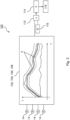
- a fuel cell electric vehicle according to an embodiment of the invention,
- Fig. 2
- a method according to an embodiment of the invention,
- Fig. 3
- the method of
Fig. 2 with a normal temperature threshold range illustrated in an exemplary way, and - Fig. 4
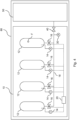
- the fuel cell electric vehicle of
Fig. 1 with a fault illustrated in an exemplary way. - Identical or functionally identical elements are each designated with the same reference sign in
Figures 1 to 4 . -
Figure 1 shows schematically a fuel cellelectric vehicle 60 comprising atank system 10 and afuel cell system 50. Thetank system 10 is a hydrogen tank system storing hydrogen for supply to thefuel cell system 50. Thetank system 10 is fluidically connected via a commonhydrogen supply line 18 to thefuel cell system 50, in particular a main supply line (not shown) of thefuel cell system 50. Acommon valve 40 in the commonhydrogen supply line 18 is provided for regulating the hydrogen flow from thetank system 10 to thefuel cell system 50. - The
fuel cell system 50 comprises one or multiple fuel cell stacks and balance of plants periphery, such as pumps, sensors, heat exchangers, seals, compressors, recirculation blowers, intercoolers and humidifiers. Although not shown, the fuel cellelectric vehicle 60 may comprise one or multiple electric motors for driving the fuel cellelectric vehicle 60. By means of supplying thefuel cell system 50 of the fuel cellelectric vehicle 60 with hydrogen from thetank system 10, electricity is produced by thefuel cell system 50 and this electricity is supplied to the electric motor(s) of the fuel cellelectric vehicle 60. - During normal operation of the fuel cell
electric vehicle 60, the fuel cellelectric vehicle 60 is safe to be operated. However, there may be a fault F (seeFig. 4 ), such as shown inFig. 4 as a leak in the last one or fourth (counted from left to right) of the exemplary fourindividual tanks 12 of thetank system 10, which may render the further operation of the fuel cellelectric vehicle 60 potentially dangerous. - In order to detect such fault F, the common
hydrogen supply line 18 is provided with acommon pressure sensor 30. Each one of theindividual tanks 12 is fluidically connected via the commonhydrogen supply line 18 to thefuel cell system 50. Accordingly, a common pressure P reading of thecommon pressure sensor 30 may be checked against a predefined normal common pressure threshold range and, if the common pressure P is outside that range, the fault F may be detected. Accordingly, the driver of the fuel cellelectric vehicle 60 may be notified of the fault and appropriate measures, such as shut-off of the fuel cellelectric vehicle 60, notifying assistance, driving to a repair shop etc., in particular depending on the extent of the leak, may be taken. - However, by means of the
common pressure sensor 30 it is not possible to identify the fourthindividual tank 12 as having the fault F. In this exemplary case, in order to detect and pinpoint the fault F to the fourthindividual tank 12, the now explained method 100 (seeFigs. 2 and3 ) is being used. - The
method 100, which is at least partially shown inFigs. 2 and3 , is executed by acontrol unit 20, which may comprise or be a computer, of thetank system 10. Thecontrol unit 20 is logically connected toindividual temperature sensors 14 of theindividual tanks 12 for measuring the internal temperature of theindividual tanks 12. Accordingly, thecontrol unit 20 receives the individual temperatures T from thetemperature sensors 14. - Moreover, the
control unit 20 is logically connected totank valves 16 individually provided as periphery of each one of theindividual tanks 12. Thetank valves 16 are provided between theindividual tanks 12 and the commonhydrogen supply line 18. Thecontrol unit 20 is configured to control thetank valves 16. Accordingly, thecontrol unit 20 may turn on or shut off theindividual tank valves 16. - The
method 100 in afirst step 102 comprises receiving the individual temperatures T as readings from theindividual temperature sensors 14. Thisfirst step 102, as well as the further steps of themethod 100, are performed continuously as may be taken from the graph showing the individual temperatures T of theindividual tanks 12 over time t. - From this graph it can be taken that one of the individual temperatures T, in this exemplary case namely the one of the fourth
individual tank 12, is significantly lower than the other individual temperatures T. However, this alone is not sufficient to judge whether there is actually a fault F in the fourthindividual tank 12 because there is no comparative measure. - The
method 100 therefore continues in a second step 104 (not explicitly shown) with calculating a first average value of the individual temperatures T and a deviation value of the individual temperatures around the first average value. The first average value preferably is a mean of the individual temperatures T. The deviation value preferably is a standard deviation of the individual temperatures T around the first average value. - In a third step 106 (not explicitly shown) of the
method 100, it is checked whether the calculated deviation value exceeds a predetermined deviation value threshold, which may be calculated based on the deviation value. - Then, in a fourth step 108 (not explicitly shown) of
method 100, a fault F of thetank system 10 may be detected if the deviation value exceeds the predetermined deviation value threshold. Accordingly, based on the deviation value threshold, it is determined whether or not there is a fault F in thetank system 10. If a fault F is not detected, themethod 100 can be repeated with thefirst step 102 through fourth step 108. - The proposed fault detection is highly reliable to detect that one or more of the
tanks 12 have a fault F. The proposed fault detection is also able to quantify the magnitude of the fault. However, thereby alone it is not possible to exactly pinpoint which one or ones of thetanks 12 has or have the fault F. - For this reason, in a
fifth step 110 ofmethod 100, a normal temperature threshold range R is calculated by thecontrol unit 20 based on the individual temperatures T of the individual tanks 12 (seeFig. 3 ). The normal temperature threshold range R is preferably calculated based on a second average value of the individual temperatures, which may be calculated before thefifth step 110 and which preferably is a median of all individual temperatures T, and the deviation value, in particular standard deviation, of the individual temperatures T such that the limits of the normal temperature threshold range R around the median are proportionate to the standard deviation. In other words, the normal temperature threshold range R may include the median and have an upper and lower boundary considering or corresponding to the standard deviation calculated in thesecond step 104 ofmethod 100. - The normal temperature threshold R is shown with its limits in the graph of individual temperatures T over time t in
Fig. 3 . - In a
sixth step 112 ofmethod 100, it is checked if all of the individual temperatures T are within the normal temperature threshold range R. If this is the case, the first through sixth step 102-112 or only thefifth step 110 andsixth step 112 may be repeated. - If this is not the case, i.e., one of the individual temperatures T is not within the normal temperature threshold range R, such as it is the case with the individual temperature T of the fourth
individual tank 12 due to the fault F in form of the leak therein as seen inFig. 4 , in aseventh step 114 ofmethod 100 the fault F is detected of theindividual tank 12 exhibiting the individual temperature T being outside of the normal temperature threshold range R. - Consequently, an
eighth step 116 of themethod 100 may be carried out, in which thetank valve 16 associated with the faultyindividual tank 12 is shut off. Thereby, no hydrogen from the faultyindividual tank 12 can be transported via the commonhydrogen supply line 18 to thefuel cell system 50 for safety purposes. - Now that the faulty
individual tank 12 is known, a consequent repair can be carried out faster because the fault F is already narrowed down to one of theindividual tanks 12, whereby it is not necessary anymore to search for the fault F in all of theindividual tanks 12. - The foregoing explanations of embodiments describe the present invention by way of example only.
-
- 10
- tank system
- 12
- individual tank
- 14
- temperature sensor
- 16
- tank valve
- 18
- common hydrogen supply line
- 20
- control unit
- 30
- common pressure sensor
- 40
- common valve
- 50
- fuel cell system
- 60
- fuel cell electric vehicle
- 100
- method
- 102
- first step
- 104
- second step
- 106
- third step
- 108
- fourth step
- 110
- fifth step
- 112
- sixth step
- 114
- seventh step
- 116
- eighth step
- F
- fault
- P
- common pressure
- R
- normal temperature threshold range
- T
- individual temperature
- t
- time
Claims (15)
- Method (100) for detecting a fault (F) in a tank system (10) comprising multiple individual tanks (12) for storing hydrogen connected to a common hydrogen supply line (18), wherein the method (100) is characterized by the following steps:- receiving individual temperatures (T) of each one of the individual tanks (12),- calculating at least one average value of the individual temperatures (T) and a deviation value of the individual temperatures (T) around one of the at least one average value,- checking if the deviation value is exceeding a predetermined deviation value threshold,- detecting a fault (F) of the tank system (10) if the deviation value is exceeding the predetermined deviation value threshold,- calculating a normal temperature threshold range (R) based on one of the at least one average value and the deviation value,- checking if all of the individual temperatures (T) are within the normal temperature threshold range (R), and- detecting a fault (F) of an individual tank (12) if its individual temperature (T) is outside of the normal temperature threshold range (R).
- Method (100) according to claim 1, characterized in that an operation of the detected individual tank (12) having the fault (F) is shut off.
- Method (100) according to any of the previous claims, characterized in that the average value around which the deviation value is calculated is a first average value, wherein the first average value is a mean of the individual temperatures (T).
- Method (100) according to claim 3, characterized in that the deviation value is a standard deviation of the individual temperatures (T) around the first average value.
- Method (100) according to any of the previous claims, characterized in that the average value based on which the normal temperature threshold range (R) is calculated is a second average value, wherein the second average value is a median of the individual temperatures (T).
- Method (100) according to any of the previous claims, characterized in that at least some of the steps of the method (100) are repeated continuously.
- Method (100) according to any of the previous claims, characterized in that the common hydrogen supply line (18) comprises a common pressure sensor (30) for measuring the pressure (P) of the hydrogen in the common hydrogen supply line (18).
- Method (100) according to any of the previous claims, characterized in that the fault (F) is a leak of an individual tank (12) or a fault (F) of a tank valve (16) connecting the individual tank (12) with the common hydrogen supply line (18).
- Method (100) according to any of the previous claims, characterized in that the individual temperatures (T) are measured by individual temperature sensors (14) of each one of the individual tanks (12).
- Method (100) according to any of the previous claims, characterized in that the individual temperatures (T) are internal temperatures of the hydrogen inside of the individual tanks (12).
- Method (100) according to any of the previous claims, characterized in that each one of the individual tanks (12) is connected via an individual tank valve (16) to the common hydrogen supply line (18).
- Method (100) according to any of the previous claims, characterized in that the tank system (10) is a hydrogen tank system of a fuel cell electric vehicle (60).
- Computer program product comprising instructions which, when the program is executed by a computer, cause the computer to perform the method (100) according to any of the previous claims.
- Tank system (10) comprising multiple individual tanks (12) for storing hydrogen connected to a common hydrogen supply line (18), wherein the tank system (10) comprises a control unit (20) configured to carry out the method (100) according to any of claims 1 to 12.
- Fuel cell electric vehicle (60) characterized in that it comprises the tank system (10) according to claim 14 and a fuel cell system (50) fluidically connected to the common hydrogen supply line (18) for supplying the fuel cell system (50) with hydrogen from the tank system (10).
Priority Applications (1)
| Application Number | Priority Date | Filing Date | Title |
|---|---|---|---|
| EP22192542.3A EP4331898B1 (en) | 2022-08-29 | 2022-08-29 | Method for detecting a fault in a tank system, computer program product, tank system and fuel cell electric vehicle |
Applications Claiming Priority (1)
| Application Number | Priority Date | Filing Date | Title |
|---|---|---|---|
| EP22192542.3A EP4331898B1 (en) | 2022-08-29 | 2022-08-29 | Method for detecting a fault in a tank system, computer program product, tank system and fuel cell electric vehicle |
Publications (2)
| Publication Number | Publication Date |
|---|---|
| EP4331898A1 true EP4331898A1 (en) | 2024-03-06 |
| EP4331898B1 EP4331898B1 (en) | 2025-09-24 |
Family
ID=83444851
Family Applications (1)
| Application Number | Title | Priority Date | Filing Date |
|---|---|---|---|
| EP22192542.3A Active EP4331898B1 (en) | 2022-08-29 | 2022-08-29 | Method for detecting a fault in a tank system, computer program product, tank system and fuel cell electric vehicle |
Country Status (1)
| Country | Link |
|---|---|
| EP (1) | EP4331898B1 (en) |
Cited By (1)
| Publication number | Priority date | Publication date | Assignee | Title |
|---|---|---|---|---|
| WO2026064773A1 (en) * | 2024-09-23 | 2026-03-26 | Hyroad Networks Llc | Systems and methods for hydrogen tank assembly diagnostics |
Citations (3)
| Publication number | Priority date | Publication date | Assignee | Title |
|---|---|---|---|---|
| US20150134277A1 (en) * | 2012-03-21 | 2015-05-14 | Audi Ag | Method for checking the gas tightness of a fuel cell system |
| DE102014213745A1 (en) * | 2014-07-15 | 2016-01-21 | Robert Bosch Gmbh | Method for detecting a leak |
| CN110926707A (en) * | 2019-12-13 | 2020-03-27 | 潍柴动力股份有限公司 | Method, device and equipment for detecting leakage of hydrogen storage system |
-
2022
- 2022-08-29 EP EP22192542.3A patent/EP4331898B1/en active Active
Patent Citations (3)
| Publication number | Priority date | Publication date | Assignee | Title |
|---|---|---|---|---|
| US20150134277A1 (en) * | 2012-03-21 | 2015-05-14 | Audi Ag | Method for checking the gas tightness of a fuel cell system |
| DE102014213745A1 (en) * | 2014-07-15 | 2016-01-21 | Robert Bosch Gmbh | Method for detecting a leak |
| CN110926707A (en) * | 2019-12-13 | 2020-03-27 | 潍柴动力股份有限公司 | Method, device and equipment for detecting leakage of hydrogen storage system |
Cited By (1)
| Publication number | Priority date | Publication date | Assignee | Title |
|---|---|---|---|---|
| WO2026064773A1 (en) * | 2024-09-23 | 2026-03-26 | Hyroad Networks Llc | Systems and methods for hydrogen tank assembly diagnostics |
Also Published As
| Publication number | Publication date |
|---|---|
| EP4331898B1 (en) | 2025-09-24 |
Similar Documents
| Publication | Publication Date | Title |
|---|---|---|
| EP3905263A1 (en) | Nuclear power plant leakage monitoring alarm method and alarm system | |
| US20230187666A1 (en) | Hydrogen leak sensing device and method for fuel cell vehicle | |
| US9284895B2 (en) | Methods and apparatuses for diagnosing leaks in a compressed natural gas delivery system | |
| US12188620B2 (en) | Control unit and method for operating a pressure vessel valve of a pressure vessel | |
| JP2010521625A (en) | Diagnosis method of shut-off valve | |
| US11626629B2 (en) | Method for performing a test of a thermal management system | |
| US20120318368A1 (en) | Leak detection logic for closed-volume system | |
| CN105221307A (en) | For the system of the detection air filter situation of internal-combustion engine | |
| US11196067B2 (en) | Leakage monitoring of a fuel cell system | |
| CN108953295B (en) | Pipe burst detection system and detection method for hydraulic motor endurance test | |
| US20220397479A1 (en) | Leak detection for pressurized fluid systems | |
| EP3379218A1 (en) | Method for providing a diagnostic on a combined humidity and temperature sensor | |
| EP4331898B1 (en) | Method for detecting a fault in a tank system, computer program product, tank system and fuel cell electric vehicle | |
| CN103423439A (en) | Method for detecting loss of fluid or blockage in a hydraulic circuit using exponentially weighted moving average (EWMA) filter | |
| KR101509971B1 (en) | Hydrogen Tank Temperature Sensor failure Management Method and Safe Improving System therefor | |
| CN120548432A (en) | Tank system and method for monitoring the tightness of a tank system | |
| CN110410943A (en) | A kind of return oil detection method, system and air conditioner | |
| JP7668897B2 (en) | How to Calibrate a Fuel Sensor | |
| EP4307414A1 (en) | Method for detecting a hydrogen leak in a fuel cell electric vehicle, computer program product, leakage detection system and fuel cell electric vehicle | |
| US7359790B2 (en) | Apparatus for converting energy that can be operated with fuel, in particular fuel cell assembly | |
| CA2580408C (en) | Aircraft fuel storage leak detection method and detection circuit therefor | |
| EP4300066A1 (en) | An automatic liquid tank jacket testing apparatus | |
| US12000758B2 (en) | Leak detection for pressurized fluid systems | |
| US11280358B2 (en) | Method for monitoring the condition of the hydraulic system | |
| KR102571200B1 (en) | Evaluation method for impact of abnormal operation of pumps and valves |
Legal Events
| Date | Code | Title | Description |
|---|---|---|---|
| PUAI | Public reference made under article 153(3) epc to a published international application that has entered the european phase |
Free format text: ORIGINAL CODE: 0009012 |
|
| STAA | Information on the status of an ep patent application or granted ep patent |
Free format text: STATUS: THE APPLICATION HAS BEEN PUBLISHED |
|
| AK | Designated contracting states |
Kind code of ref document: A1 Designated state(s): AL AT BE BG CH CY CZ DE DK EE ES FI FR GB GR HR HU IE IS IT LI LT LU LV MC MK MT NL NO PL PT RO RS SE SI SK SM TR |
|
| P01 | Opt-out of the competence of the unified patent court (upc) registered |
Effective date: 20240516 |
|
| STAA | Information on the status of an ep patent application or granted ep patent |
Free format text: STATUS: REQUEST FOR EXAMINATION WAS MADE |
|
| 17P | Request for examination filed |
Effective date: 20240703 |
|
| RBV | Designated contracting states (corrected) |
Designated state(s): AL AT BE BG CH CY CZ DE DK EE ES FI FR GB GR HR HU IE IS IT LI LT LU LV MC MK MT NL NO PL PT RO RS SE SI SK SM TR |
|
| RIC1 | Information provided on ipc code assigned before grant |
Ipc: H01M 8/04664 20160101ALI20250417BHEP Ipc: H01M 8/04082 20160101ALI20250417BHEP Ipc: F17C 13/12 20060101ALI20250417BHEP Ipc: B60L 3/00 20190101ALI20250417BHEP Ipc: G01M 3/00 20060101ALI20250417BHEP Ipc: F17C 13/02 20060101ALI20250417BHEP Ipc: H01M 8/0432 20160101ALI20250417BHEP Ipc: B60L 58/30 20190101ALI20250417BHEP Ipc: B60L 50/72 20190101AFI20250417BHEP |
|
| GRAP | Despatch of communication of intention to grant a patent |
Free format text: ORIGINAL CODE: EPIDOSNIGR1 |
|
| STAA | Information on the status of an ep patent application or granted ep patent |
Free format text: STATUS: GRANT OF PATENT IS INTENDED |
|
| INTG | Intention to grant announced |
Effective date: 20250605 |
|
| GRAS | Grant fee paid |
Free format text: ORIGINAL CODE: EPIDOSNIGR3 |
|
| GRAA | (expected) grant |
Free format text: ORIGINAL CODE: 0009210 |
|
| STAA | Information on the status of an ep patent application or granted ep patent |
Free format text: STATUS: THE PATENT HAS BEEN GRANTED |
|
| AK | Designated contracting states |
Kind code of ref document: B1 Designated state(s): AL AT BE BG CH CY CZ DE DK EE ES FI FR GB GR HR HU IE IS IT LI LT LU LV MC MK MT NL NO PL PT RO RS SE SI SK SM TR |
|
| REG | Reference to a national code |
Ref country code: GB Ref legal event code: FG4D |
|
| REG | Reference to a national code |
Ref country code: CH Ref legal event code: EP |
|
| REG | Reference to a national code |
Ref country code: DE Ref legal event code: R096 Ref document number: 602022021872 Country of ref document: DE |
|
| REG | Reference to a national code |
Ref country code: IE Ref legal event code: FG4D |
|
| PG25 | Lapsed in a contracting state [announced via postgrant information from national office to epo] |
Ref country code: NO Free format text: LAPSE BECAUSE OF FAILURE TO SUBMIT A TRANSLATION OF THE DESCRIPTION OR TO PAY THE FEE WITHIN THE PRESCRIBED TIME-LIMIT Effective date: 20251224 |
|
| REG | Reference to a national code |
Ref country code: LT Ref legal event code: MG9D |
|
| PG25 | Lapsed in a contracting state [announced via postgrant information from national office to epo] |
Ref country code: FI Free format text: LAPSE BECAUSE OF FAILURE TO SUBMIT A TRANSLATION OF THE DESCRIPTION OR TO PAY THE FEE WITHIN THE PRESCRIBED TIME-LIMIT Effective date: 20250924 |
|
| PG25 | Lapsed in a contracting state [announced via postgrant information from national office to epo] |
Ref country code: HR Free format text: LAPSE BECAUSE OF FAILURE TO SUBMIT A TRANSLATION OF THE DESCRIPTION OR TO PAY THE FEE WITHIN THE PRESCRIBED TIME-LIMIT Effective date: 20250924 |
|
| PG25 | Lapsed in a contracting state [announced via postgrant information from national office to epo] |
Ref country code: GR Free format text: LAPSE BECAUSE OF FAILURE TO SUBMIT A TRANSLATION OF THE DESCRIPTION OR TO PAY THE FEE WITHIN THE PRESCRIBED TIME-LIMIT Effective date: 20251225 |
|
| PG25 | Lapsed in a contracting state [announced via postgrant information from national office to epo] |
Ref country code: SE Free format text: LAPSE BECAUSE OF FAILURE TO SUBMIT A TRANSLATION OF THE DESCRIPTION OR TO PAY THE FEE WITHIN THE PRESCRIBED TIME-LIMIT Effective date: 20250924 |
|
| PG25 | Lapsed in a contracting state [announced via postgrant information from national office to epo] |
Ref country code: LV Free format text: LAPSE BECAUSE OF FAILURE TO SUBMIT A TRANSLATION OF THE DESCRIPTION OR TO PAY THE FEE WITHIN THE PRESCRIBED TIME-LIMIT Effective date: 20250924 |
|
| PG25 | Lapsed in a contracting state [announced via postgrant information from national office to epo] |
Ref country code: BG Free format text: LAPSE BECAUSE OF FAILURE TO SUBMIT A TRANSLATION OF THE DESCRIPTION OR TO PAY THE FEE WITHIN THE PRESCRIBED TIME-LIMIT Effective date: 20250924 |
|
| PG25 | Lapsed in a contracting state [announced via postgrant information from national office to epo] |
Ref country code: RS Free format text: LAPSE BECAUSE OF FAILURE TO SUBMIT A TRANSLATION OF THE DESCRIPTION OR TO PAY THE FEE WITHIN THE PRESCRIBED TIME-LIMIT Effective date: 20251224 |
|
| REG | Reference to a national code |
Ref country code: NL Ref legal event code: MP Effective date: 20250924 |
|
| PG25 | Lapsed in a contracting state [announced via postgrant information from national office to epo] |
Ref country code: NL Free format text: LAPSE BECAUSE OF FAILURE TO SUBMIT A TRANSLATION OF THE DESCRIPTION OR TO PAY THE FEE WITHIN THE PRESCRIBED TIME-LIMIT Effective date: 20250924 |
|
| REG | Reference to a national code |
Ref country code: AT Ref legal event code: MK05 Ref document number: 1840140 Country of ref document: AT Kind code of ref document: T Effective date: 20250924 |
|
| PG25 | Lapsed in a contracting state [announced via postgrant information from national office to epo] |
Ref country code: SM Free format text: LAPSE BECAUSE OF FAILURE TO SUBMIT A TRANSLATION OF THE DESCRIPTION OR TO PAY THE FEE WITHIN THE PRESCRIBED TIME-LIMIT Effective date: 20250924 |
|
| PG25 | Lapsed in a contracting state [announced via postgrant information from national office to epo] |
Ref country code: ES Free format text: LAPSE BECAUSE OF FAILURE TO SUBMIT A TRANSLATION OF THE DESCRIPTION OR TO PAY THE FEE WITHIN THE PRESCRIBED TIME-LIMIT Effective date: 20250924 |
|
| PG25 | Lapsed in a contracting state [announced via postgrant information from national office to epo] |
Ref country code: AT Free format text: LAPSE BECAUSE OF FAILURE TO SUBMIT A TRANSLATION OF THE DESCRIPTION OR TO PAY THE FEE WITHIN THE PRESCRIBED TIME-LIMIT Effective date: 20250924 |
|
| PG25 | Lapsed in a contracting state [announced via postgrant information from national office to epo] |
Ref country code: IT Free format text: LAPSE BECAUSE OF FAILURE TO SUBMIT A TRANSLATION OF THE DESCRIPTION OR TO PAY THE FEE WITHIN THE PRESCRIBED TIME-LIMIT Effective date: 20250924 |
|
| PG25 | Lapsed in a contracting state [announced via postgrant information from national office to epo] |
Ref country code: IS Free format text: LAPSE BECAUSE OF FAILURE TO SUBMIT A TRANSLATION OF THE DESCRIPTION OR TO PAY THE FEE WITHIN THE PRESCRIBED TIME-LIMIT Effective date: 20260124 |
|
| PG25 | Lapsed in a contracting state [announced via postgrant information from national office to epo] |
Ref country code: CZ Free format text: LAPSE BECAUSE OF FAILURE TO SUBMIT A TRANSLATION OF THE DESCRIPTION OR TO PAY THE FEE WITHIN THE PRESCRIBED TIME-LIMIT Effective date: 20250924 Ref country code: PT Free format text: LAPSE BECAUSE OF FAILURE TO SUBMIT A TRANSLATION OF THE DESCRIPTION OR TO PAY THE FEE WITHIN THE PRESCRIBED TIME-LIMIT Effective date: 20260126 |
|
| PG25 | Lapsed in a contracting state [announced via postgrant information from national office to epo] |
Ref country code: PL Free format text: LAPSE BECAUSE OF FAILURE TO SUBMIT A TRANSLATION OF THE DESCRIPTION OR TO PAY THE FEE WITHIN THE PRESCRIBED TIME-LIMIT Effective date: 20250924 |
|
| PG25 | Lapsed in a contracting state [announced via postgrant information from national office to epo] |
Ref country code: EE Free format text: LAPSE BECAUSE OF FAILURE TO SUBMIT A TRANSLATION OF THE DESCRIPTION OR TO PAY THE FEE WITHIN THE PRESCRIBED TIME-LIMIT Effective date: 20250924 Ref country code: SK Free format text: LAPSE BECAUSE OF FAILURE TO SUBMIT A TRANSLATION OF THE DESCRIPTION OR TO PAY THE FEE WITHIN THE PRESCRIBED TIME-LIMIT Effective date: 20250924 |