EP4331894A1 - Powertrain, control method, and hybrid electric vehicle - Google Patents
Powertrain, control method, and hybrid electric vehicle Download PDFInfo
- Publication number
- EP4331894A1 EP4331894A1 EP23187182.3A EP23187182A EP4331894A1 EP 4331894 A1 EP4331894 A1 EP 4331894A1 EP 23187182 A EP23187182 A EP 23187182A EP 4331894 A1 EP4331894 A1 EP 4331894A1
- Authority
- EP
- European Patent Office
- Prior art keywords
- motor
- power battery
- bridge arm
- voltage
- bus
- Prior art date
- Legal status (The legal status is an assumption and is not a legal conclusion. Google has not performed a legal analysis and makes no representation as to the accuracy of the status listed.)
- Pending
Links
Images








Classifications
-
- B—PERFORMING OPERATIONS; TRANSPORTING
- B60—VEHICLES IN GENERAL
- B60L—PROPULSION OF ELECTRICALLY-PROPELLED VEHICLES; SUPPLYING ELECTRIC POWER FOR AUXILIARY EQUIPMENT OF ELECTRICALLY-PROPELLED VEHICLES; ELECTRODYNAMIC BRAKE SYSTEMS FOR VEHICLES IN GENERAL; MAGNETIC SUSPENSION OR LEVITATION FOR VEHICLES; MONITORING OPERATING VARIABLES OF ELECTRICALLY-PROPELLED VEHICLES; ELECTRIC SAFETY DEVICES FOR ELECTRICALLY-PROPELLED VEHICLES
- B60L50/00—Electric propulsion with power supplied within the vehicle
- B60L50/50—Electric propulsion with power supplied within the vehicle using propulsion power supplied by batteries or fuel cells
- B60L50/60—Electric propulsion with power supplied within the vehicle using propulsion power supplied by batteries or fuel cells using power supplied by batteries
- B60L50/61—Electric propulsion with power supplied within the vehicle using propulsion power supplied by batteries or fuel cells using power supplied by batteries by batteries charged by engine-driven generators, e.g. series hybrid electric vehicles
-
- H—ELECTRICITY
- H02—GENERATION; CONVERSION OR DISTRIBUTION OF ELECTRIC POWER
- H02P—CONTROL OR REGULATION OF ELECTRIC MOTORS, ELECTRIC GENERATORS OR DYNAMO-ELECTRIC CONVERTERS; CONTROLLING TRANSFORMERS, REACTORS OR CHOKE COILS
- H02P5/00—Arrangements specially adapted for regulating or controlling the speed or torque of two or more electric motors
- H02P5/74—Arrangements specially adapted for regulating or controlling the speed or torque of two or more electric motors controlling two or more AC dynamo-electric motors
-
- B—PERFORMING OPERATIONS; TRANSPORTING
- B60—VEHICLES IN GENERAL
- B60K—ARRANGEMENT OR MOUNTING OF PROPULSION UNITS OR OF TRANSMISSIONS IN VEHICLES; ARRANGEMENT OR MOUNTING OF PLURAL DIVERSE PRIME-MOVERS IN VEHICLES; AUXILIARY DRIVES FOR VEHICLES; INSTRUMENTATION OR DASHBOARDS FOR VEHICLES; ARRANGEMENTS IN CONNECTION WITH COOLING, AIR INTAKE, GAS EXHAUST OR FUEL SUPPLY OF PROPULSION UNITS IN VEHICLES
- B60K6/00—Arrangement or mounting of plural diverse prime-movers for mutual or common propulsion, e.g. hybrid propulsion systems comprising electric motors and internal combustion engines
- B60K6/20—Arrangement or mounting of plural diverse prime-movers for mutual or common propulsion, e.g. hybrid propulsion systems comprising electric motors and internal combustion engines the prime-movers consisting of electric motors and internal combustion engines, e.g. HEVs
- B60K6/22—Arrangement or mounting of plural diverse prime-movers for mutual or common propulsion, e.g. hybrid propulsion systems comprising electric motors and internal combustion engines the prime-movers consisting of electric motors and internal combustion engines, e.g. HEVs characterised by apparatus, components or means specially adapted for HEVs
- B60K6/26—Arrangement or mounting of plural diverse prime-movers for mutual or common propulsion, e.g. hybrid propulsion systems comprising electric motors and internal combustion engines the prime-movers consisting of electric motors and internal combustion engines, e.g. HEVs characterised by apparatus, components or means specially adapted for HEVs characterised by the motors or the generators
-
- B—PERFORMING OPERATIONS; TRANSPORTING
- B60—VEHICLES IN GENERAL
- B60L—PROPULSION OF ELECTRICALLY-PROPELLED VEHICLES; SUPPLYING ELECTRIC POWER FOR AUXILIARY EQUIPMENT OF ELECTRICALLY-PROPELLED VEHICLES; ELECTRODYNAMIC BRAKE SYSTEMS FOR VEHICLES IN GENERAL; MAGNETIC SUSPENSION OR LEVITATION FOR VEHICLES; MONITORING OPERATING VARIABLES OF ELECTRICALLY-PROPELLED VEHICLES; ELECTRIC SAFETY DEVICES FOR ELECTRICALLY-PROPELLED VEHICLES
- B60L15/00—Methods, circuits, or devices for controlling the traction-motor speed of electrically-propelled vehicles
- B60L15/007—Physical arrangements or structures of drive train converters specially adapted for the propulsion motors of electric vehicles
-
- B—PERFORMING OPERATIONS; TRANSPORTING
- B60—VEHICLES IN GENERAL
- B60W—CONJOINT CONTROL OF VEHICLE SUB-UNITS OF DIFFERENT TYPE OR DIFFERENT FUNCTION; CONTROL SYSTEMS SPECIALLY ADAPTED FOR HYBRID VEHICLES; ROAD VEHICLE DRIVE CONTROL SYSTEMS FOR PURPOSES NOT RELATED TO THE CONTROL OF A PARTICULAR SUB-UNIT
- B60W20/00—Control systems specially adapted for hybrid vehicles
-
- H—ELECTRICITY
- H02—GENERATION; CONVERSION OR DISTRIBUTION OF ELECTRIC POWER
- H02P—CONTROL OR REGULATION OF ELECTRIC MOTORS, ELECTRIC GENERATORS OR DYNAMO-ELECTRIC CONVERTERS; CONTROLLING TRANSFORMERS, REACTORS OR CHOKE COILS
- H02P27/00—Arrangements or methods for the control of AC motors characterised by the kind of supply voltage
- H02P27/04—Arrangements or methods for the control of AC motors characterised by the kind of supply voltage using variable-frequency supply voltage, e.g. inverter or converter supply voltage
- H02P27/06—Arrangements or methods for the control of AC motors characterised by the kind of supply voltage using variable-frequency supply voltage, e.g. inverter or converter supply voltage using DC to AC converters or inverters
- H02P27/08—Arrangements or methods for the control of AC motors characterised by the kind of supply voltage using variable-frequency supply voltage, e.g. inverter or converter supply voltage using DC to AC converters or inverters with pulse width modulation
-
- B—PERFORMING OPERATIONS; TRANSPORTING
- B60—VEHICLES IN GENERAL
- B60L—PROPULSION OF ELECTRICALLY-PROPELLED VEHICLES; SUPPLYING ELECTRIC POWER FOR AUXILIARY EQUIPMENT OF ELECTRICALLY-PROPELLED VEHICLES; ELECTRODYNAMIC BRAKE SYSTEMS FOR VEHICLES IN GENERAL; MAGNETIC SUSPENSION OR LEVITATION FOR VEHICLES; MONITORING OPERATING VARIABLES OF ELECTRICALLY-PROPELLED VEHICLES; ELECTRIC SAFETY DEVICES FOR ELECTRICALLY-PROPELLED VEHICLES
- B60L2210/00—Converter types
- B60L2210/10—DC to DC converters
-
- B—PERFORMING OPERATIONS; TRANSPORTING
- B60—VEHICLES IN GENERAL
- B60L—PROPULSION OF ELECTRICALLY-PROPELLED VEHICLES; SUPPLYING ELECTRIC POWER FOR AUXILIARY EQUIPMENT OF ELECTRICALLY-PROPELLED VEHICLES; ELECTRODYNAMIC BRAKE SYSTEMS FOR VEHICLES IN GENERAL; MAGNETIC SUSPENSION OR LEVITATION FOR VEHICLES; MONITORING OPERATING VARIABLES OF ELECTRICALLY-PROPELLED VEHICLES; ELECTRIC SAFETY DEVICES FOR ELECTRICALLY-PROPELLED VEHICLES
- B60L2210/00—Converter types
- B60L2210/30—AC to DC converters
-
- B—PERFORMING OPERATIONS; TRANSPORTING
- B60—VEHICLES IN GENERAL
- B60L—PROPULSION OF ELECTRICALLY-PROPELLED VEHICLES; SUPPLYING ELECTRIC POWER FOR AUXILIARY EQUIPMENT OF ELECTRICALLY-PROPELLED VEHICLES; ELECTRODYNAMIC BRAKE SYSTEMS FOR VEHICLES IN GENERAL; MAGNETIC SUSPENSION OR LEVITATION FOR VEHICLES; MONITORING OPERATING VARIABLES OF ELECTRICALLY-PROPELLED VEHICLES; ELECTRIC SAFETY DEVICES FOR ELECTRICALLY-PROPELLED VEHICLES
- B60L50/00—Electric propulsion with power supplied within the vehicle
- B60L50/10—Electric propulsion with power supplied within the vehicle using propulsion power supplied by engine-driven generators, e.g. generators driven by combustion engines
-
- B—PERFORMING OPERATIONS; TRANSPORTING
- B60—VEHICLES IN GENERAL
- B60L—PROPULSION OF ELECTRICALLY-PROPELLED VEHICLES; SUPPLYING ELECTRIC POWER FOR AUXILIARY EQUIPMENT OF ELECTRICALLY-PROPELLED VEHICLES; ELECTRODYNAMIC BRAKE SYSTEMS FOR VEHICLES IN GENERAL; MAGNETIC SUSPENSION OR LEVITATION FOR VEHICLES; MONITORING OPERATING VARIABLES OF ELECTRICALLY-PROPELLED VEHICLES; ELECTRIC SAFETY DEVICES FOR ELECTRICALLY-PROPELLED VEHICLES
- B60L50/00—Electric propulsion with power supplied within the vehicle
- B60L50/10—Electric propulsion with power supplied within the vehicle using propulsion power supplied by engine-driven generators, e.g. generators driven by combustion engines
- B60L50/13—Electric propulsion with power supplied within the vehicle using propulsion power supplied by engine-driven generators, e.g. generators driven by combustion engines using AC generators and AC motors
-
- B—PERFORMING OPERATIONS; TRANSPORTING
- B60—VEHICLES IN GENERAL
- B60L—PROPULSION OF ELECTRICALLY-PROPELLED VEHICLES; SUPPLYING ELECTRIC POWER FOR AUXILIARY EQUIPMENT OF ELECTRICALLY-PROPELLED VEHICLES; ELECTRODYNAMIC BRAKE SYSTEMS FOR VEHICLES IN GENERAL; MAGNETIC SUSPENSION OR LEVITATION FOR VEHICLES; MONITORING OPERATING VARIABLES OF ELECTRICALLY-PROPELLED VEHICLES; ELECTRIC SAFETY DEVICES FOR ELECTRICALLY-PROPELLED VEHICLES
- B60L50/00—Electric propulsion with power supplied within the vehicle
- B60L50/10—Electric propulsion with power supplied within the vehicle using propulsion power supplied by engine-driven generators, e.g. generators driven by combustion engines
- B60L50/15—Electric propulsion with power supplied within the vehicle using propulsion power supplied by engine-driven generators, e.g. generators driven by combustion engines with additional electric power supply
-
- B—PERFORMING OPERATIONS; TRANSPORTING
- B60—VEHICLES IN GENERAL
- B60L—PROPULSION OF ELECTRICALLY-PROPELLED VEHICLES; SUPPLYING ELECTRIC POWER FOR AUXILIARY EQUIPMENT OF ELECTRICALLY-PROPELLED VEHICLES; ELECTRODYNAMIC BRAKE SYSTEMS FOR VEHICLES IN GENERAL; MAGNETIC SUSPENSION OR LEVITATION FOR VEHICLES; MONITORING OPERATING VARIABLES OF ELECTRICALLY-PROPELLED VEHICLES; ELECTRIC SAFETY DEVICES FOR ELECTRICALLY-PROPELLED VEHICLES
- B60L50/00—Electric propulsion with power supplied within the vehicle
- B60L50/50—Electric propulsion with power supplied within the vehicle using propulsion power supplied by batteries or fuel cells
- B60L50/51—Electric propulsion with power supplied within the vehicle using propulsion power supplied by batteries or fuel cells characterised by AC-motors
-
- B—PERFORMING OPERATIONS; TRANSPORTING
- B60—VEHICLES IN GENERAL
- B60L—PROPULSION OF ELECTRICALLY-PROPELLED VEHICLES; SUPPLYING ELECTRIC POWER FOR AUXILIARY EQUIPMENT OF ELECTRICALLY-PROPELLED VEHICLES; ELECTRODYNAMIC BRAKE SYSTEMS FOR VEHICLES IN GENERAL; MAGNETIC SUSPENSION OR LEVITATION FOR VEHICLES; MONITORING OPERATING VARIABLES OF ELECTRICALLY-PROPELLED VEHICLES; ELECTRIC SAFETY DEVICES FOR ELECTRICALLY-PROPELLED VEHICLES
- B60L50/00—Electric propulsion with power supplied within the vehicle
- B60L50/50—Electric propulsion with power supplied within the vehicle using propulsion power supplied by batteries or fuel cells
- B60L50/60—Electric propulsion with power supplied within the vehicle using propulsion power supplied by batteries or fuel cells using power supplied by batteries
-
- H—ELECTRICITY
- H02—GENERATION; CONVERSION OR DISTRIBUTION OF ELECTRIC POWER
- H02P—CONTROL OR REGULATION OF ELECTRIC MOTORS, ELECTRIC GENERATORS OR DYNAMO-ELECTRIC CONVERTERS; CONTROLLING TRANSFORMERS, REACTORS OR CHOKE COILS
- H02P2201/00—Indexing scheme relating to controlling arrangements characterised by the converter used
- H02P2201/07—DC-DC step-up or step-down converter inserted between the power supply and the inverter supplying the motor, e.g. to control voltage source fluctuations, to vary the motor speed
-
- H—ELECTRICITY
- H02—GENERATION; CONVERSION OR DISTRIBUTION OF ELECTRIC POWER
- H02P—CONTROL OR REGULATION OF ELECTRIC MOTORS, ELECTRIC GENERATORS OR DYNAMO-ELECTRIC CONVERTERS; CONTROLLING TRANSFORMERS, REACTORS OR CHOKE COILS
- H02P2209/00—Indexing scheme relating to controlling arrangements characterised by the waveform of the supplied voltage or current
- H02P2209/01—Motors with neutral point connected to the power supply
-
- Y—GENERAL TAGGING OF NEW TECHNOLOGICAL DEVELOPMENTS; GENERAL TAGGING OF CROSS-SECTIONAL TECHNOLOGIES SPANNING OVER SEVERAL SECTIONS OF THE IPC; TECHNICAL SUBJECTS COVERED BY FORMER USPC CROSS-REFERENCE ART COLLECTIONS [XRACs] AND DIGESTS
- Y02—TECHNOLOGIES OR APPLICATIONS FOR MITIGATION OR ADAPTATION AGAINST CLIMATE CHANGE
- Y02T—CLIMATE CHANGE MITIGATION TECHNOLOGIES RELATED TO TRANSPORTATION
- Y02T10/00—Road transport of goods or passengers
- Y02T10/60—Other road transportation technologies with climate change mitigation effect
- Y02T10/62—Hybrid vehicles
Definitions
- This application relates to the field of new-energy vehicle technologies, and in particular, to a powertrain, a control method, and a hybrid electric vehicle.
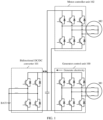
- the powertrain includes a generator M1, a generator control unit 100 connected to the generator M1, a bi-directional DC/DC converter 101, a motor M2, and a motor controller unit 102 connected to the motor M2.
- the generator M1 is driven by an engine (which may also be referred to as an internal combustion engine). In a torque outputting process, the generator M1 may convert mechanical energy into electrical energy, provide the generated electrical energy for the motor M2, and provide the generated electrical energy for a battery BAT1 by using the bi-directional DC/DC converter 101. Alternatively, the battery BAT1 may supply power to the motor M2 by using the bi-directional DC/DC converter 101. It can be learned that the power battery BAT1 can be charged or discharge. However, the bi-directional DC/DC converter 101 needs to be used for both charging and discharging of the power battery BAT1. Therefore, in addition to the generator control unit 100 and the motor controller unit 102, the powertrain of the existing hybrid electric vehicle further includes the bi-directional DC/DC converter 101, which results in high production costs of the powertrain.
- This application provides a powertrain, a control method, and a hybrid electric vehicle, to reduce production costs of the powertrain.
- an embodiment of this application provides a powertrain, where the powertrain includes a motor controller unit (Motor Controller Unit, MCU) and a motor, the MCU includes N bridge arms, and the motor includes N motor windings corresponding to the N bridge arms.
- MCU Motor Controller Unit
- the motor is in mechanical contact with a transmission system (for example, a transmission shaft), and the motor may drive a hybrid electric vehicle by using the transmission system in a torque outputting process.
- Each of the N bridge arms includes a first end and a second end, the first end of each bridge arm is connected to a positive bus, the second end of each bridge arm is connected to a negative bus, a midpoint of each bridge arm is connected to one end of one motor winding, the other end of each of the N motor windings is connected to one end of a power battery, and the other end of the power battery is connected to the positive bus or the negative bus.
- a power battery is connected to a dedicated bi-directional DC/DC converter
- the power battery is connected to the motor windings, and charging and discharging of the power battery are implemented by reusing the motor windings and the bridge arms.
- this embodiment of this application provides a structure of a new powertrain, so that a bi-directional DC/DC converter for charging and discharging a power battery can be saved, and production costs of the powertrain are reduced.
- the powertrain further includes a bus capacitor unit connected between the positive bus and the negative bus
- the MCU further includes a controller
- the N bridge arms include at least one first bridge arm
- the first bridge arm may be turned on or off based on a first pulse width modulation (Pulse Width Modulation, PWM) signal.
- PWM pulse width modulation
- the first PWM signal may enable the bus capacitor unit to charge the power battery through a motor winding connected to the first bridge arm; or the first PWM signal may enable the power battery to discharge through a motor winding connected to the first bridge arm.
- the first PWM signal is determined by the controller based on a working parameter of the motor, a bus voltage, and a voltage of the power battery.
- the bus voltage is a voltage between the positive bus and the negative bus.
- the working parameter of the motor includes at least one of an input voltage, an input current, and a rotational speed of the motor. It should be noted that the input voltage of the motor may be specifically the bus voltage.
- the first PWM signal is obtained by the controller by comparing a first modulation signal with a preset reference signal.
- the first modulation signal is obtained by the controller based on a second modulation signal and a preset target value
- the second modulation signal is determined by the controller based on a working parameter of the motor and the bus voltage
- the preset target value is determined by the controller based on the voltage of the power battery and the bus voltage.
- the first modulation signal is a sum of the second modulation signal and the preset target value.
- the first modulation signal is a difference between the second modulation signal and the preset target value.
- the powertrain further includes a bus capacitor unit connected between the positive bus and the negative bus; the MCU further includes a controller; the N bridge arms include at least one second bridge arm; and the second bridge arm may be turned on or off based on a second PWM signal.
- the second PWM signal may enable the bus capacitor unit to charge the power battery through a motor winding connected to the second bridge arm.
- the second bridge arm and the motor winding connected to the second bridge arm may implement a function of a DC/DC converter, and specifically implement a voltage step-down function of the DC/DC converter, namely, implement a function of a buck converter.
- the second PWM signal may enable the power battery to discharge through a motor winding connected to the second bridge arm.
- the second bridge arm and the motor winding connected to the second bridge arm may implement a function of a DC/DC converter, and specifically implement a voltage step-up function in the DC/DC converter, namely, implement a function of a boost converter.
- the second PWM signal is determined by the controller based on a bus voltage and a voltage of the power battery, where the bus voltage is a voltage between the positive bus and the negative bus.
- the powertrain further includes a generator control unit (Generator Control Unit, GCU) and a generator, where an input end of the GCU is connected to the generator, and an output end of the GCU is connected between the positive bus and the negative bus.
- GCU Generator Control Unit
- the generator is in direct mechanical contact with an internal combustion engine, and may be driven by the internal combustion engine. The generator may convert mechanical energy into electrical energy, and transmit the electrical energy to the motor.
- the GCU converts a voltage output by the generator to obtain a first voltage; and the MCU drives, based on the first voltage, the motor to output torque and charge the power battery.
- the first PWM signal enables the bus capacitor unit to charge the power battery through the motor winding connected to the first bridge arm, and the bus capacitor unit may provide a driving voltage for the motor. In other words, the motor outputs torque, and the power battery is in a charging state.
- energy stored in the bus capacitor unit may be provided by the generator, and the first bridge arm and the motor winding connected to the first bridge arm may ensure a function of a drive system of the motor, namely, may implement a function of a DC/AC converter.
- the first bridge arm and the motor winding connected to the first bridge arm may further implement a function of a DC/DC converter, and specifically implement a voltage step-down function of the DC/DC converter, namely, implement a function of a buck converter.
- the generator drives the motor, and the generator charges the power battery.
- the GCU when the first PWM signal enables the power battery to discharge through the motor winding connected to the first bridge arm, the GCU is configured to convert a voltage output by the generator to obtain a second voltage; and the MCU drives, based on the second voltage and the voltage of the power battery, the motor to output torque.
- the first PWM signal may enable the power battery and the generator to provide a driving voltage for the motor through the motor winding connected to the first bridge arm. In other words, the motor outputs torque, and the power battery discharges.
- the first bridge arm and the motor winding connected to the first bridge arm may ensure a function of a drive system of the motor, namely, may implement a function of a DC/AC converter.
- the first bridge arm and the motor winding connected to the first bridge arm may implement a function of a DC/DC converter, and specifically implement a voltage step-up function in the DC/DC converter, namely, implement a function of a boost converter.
- the generator and the power battery jointly drive the motor.
- the powertrain further includes a GCU and a generator, where an input end of the GCU is connected to the generator, and an output end of the GCU is connected between the positive bus and the negative bus.
- the GCU converts a voltage output by the generator to obtain a third voltage; and the MCU charges the power battery based on the third voltage.
- the second bridge arm and the motor winding connected to the second bridge arm may implement a function of a DC/DC converter, and specifically implement a voltage step-down function of the DC/DC converter, namely, implement a function of a buck converter.
- the generator charges the power battery.
- the powertrain further includes a GCU and a generator, where an input end of the GCU is connected to the generator, and an output end of the GCU is connected between the positive bus and the negative bus.
- the MCU converts a voltage of the power battery to obtain a fourth voltage; and the GCU drives the generator based on the fourth voltage.
- the second bridge arm and the motor winding connected to the second bridge arm may implement a function of a DC/DC converter, and specifically implement a voltage step-up function in the DC/DC converter, namely, implement a function of a boost converter.
- the power battery discharges to drive the generator.
- each bridge arm includes a third end, the third end of each bridge arm is connected to a neutral point of the positive bus and the negative bus, and a voltage of the neutral point is half of the voltage between the positive bus and the negative bus.
- an embodiment of this application provides a control method of a powertrain.
- the powertrain includes a motor controller unit (Motor Controller Unit, MCU), a motor, and a bus capacitor unit connected between a positive bus and a negative bus.
- MCU Motor Controller Unit
- the MCU includes N bridge arms, where the N bridge arms include at least one first bridge arm; and the motor includes N motor windings corresponding to the N bridge arms, where N is greater than or equal to 2.
- the control method is specifically implemented as follows: turning on or off the first bridge arm according to a first pulse width modulation (Pulse Width Modulation, PWM) signal, so that the bus capacitor unit charges a power battery through a motor winding connected to the first bridge arm, or a power battery discharges through a motor winding connected to the first bridge arm.
- PWM Pulse Width Modulation
- each of the N bridge arms includes a first end and a second end, the first end of each bridge arm is connected to the positive bus, and the second end of each bridge arm is connected to the negative bus; and before the turning on or off the first bridge arm according to a first PWM signal, the control method further includes: determining the first PWM signal based on a working parameter of the motor, a bus voltage, and a voltage of the power battery, where the bus voltage is a voltage between the positive bus and the negative bus.
- the determining the first PWM signal based on a working parameter of the motor, a bus voltage, and a voltage of the power battery is specifically implemented as follows: obtaining a first modulation signal based on a second modulation signal and a preset target value, and comparing the first modulation signal with a preset reference signal to obtain the first PWM signal.
- the second modulation signal is determined based on a working parameter of the motor and the bus voltage
- the preset target value is determined based on the voltage of the power battery and the bus voltage.
- the first modulation signal is a sum of the second modulation signal and the preset target value.
- the first PWM signal enables the bus capacitor unit to charge the power battery through the motor winding connected to the first bridge arm.
- the first modulation signal is a difference between the second modulation signal and the preset target value.
- the first PWM signal enables the power battery to discharge through the motor winding connected to the first bridge arm.
- the powertrain further includes a bus capacitor unit connected between the positive bus and the negative bus, and the N bridge arms include at least one second bridge arm.
- the control method may be further specifically implemented as follows: turning on or off the second bridge arm according to a second PWM signal, so that the bus capacitor unit charges the power battery through a motor winding connected to the second bridge arm; or the power battery discharges through a motor winding connected to the second bridge arm.
- the second PWM signal is determined based on a bus voltage and a voltage of the power battery, where the bus voltage is a voltage between the positive bus and the negative bus.
- an embodiment of this application provides a hybrid electric vehicle, where the hybrid electric vehicle includes a power battery and the powertrain with reference to the first aspect or any one of the foregoing possible implementations of the first aspect.
- a motor in the powertrain is connected to the power battery.
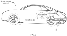
- FIG. 2 is a schematic diagram of a structure of a hybrid electric vehicle according to an embodiment of this application.
- the hybrid electric vehicle 2 includes a powertrain 20 and a power battery 21.
- the hybrid electric vehicle 2 is a new-energy vehicle with functions of both an all-electric vehicle and a gasoline-powered vehicle.
- the powertrain 20 in the hybrid electric vehicle 2 includes both a generator 201 and a motor 202.
- the hybrid electric vehicle 2 may be specifically understood as a plug-in hybrid electric vehicle (Plug-in hybrid electric vehicle, PHEV).
- the generator 201 is in direct mechanical contact with an internal combustion engine, and is driven by the internal combustion engine.
- the generator 201 may convert mechanical energy into electrical energy in a rotation (namely, torque outputting) process.
- the generator 201 may transmit the electrical energy to the motor 202.
- the generator 201 provides a driving voltage for the motor 202, to enable the motor 202 to output torque.
- the power battery 21 may also provide a driving voltage for the motor 202. In other words, the power battery 21 discharges, to enable the motor 202 to output torque.
- the generator 201 and the power battery 21 simultaneously transmit electrical energy to the motor 202. In other words, the generator 201 and the power battery 21 simultaneously provide a driving voltage for the motor 202, to enable the motor 202 to output torque.
- the motor 202 is in mechanical contact with a transmission system (for example, a transmission shaft). Therefore, the motor 202 may drive the hybrid electric vehicle 2 by using the transmission system in a torque outputting process.
- a transmission system for example, a transmission shaft
- this embodiment of this application provides a structure of a new powertrain.
- FIG. 3 is a schematic diagram of a structure of a powertrain according to an embodiment of this application.
- the powertrain provided in this embodiment of this application includes a motor controller unit (Motor Controller Unit, MCU) 300 and a motor M3.
- MCU Motor Controller Unit
- the MCU 300 includes three bridge arms, and the motor M3 includes three motor windings (for example, motor windings N U 3 , N V 3 , and N W 3 ) corresponding to the three bridge arms.
- the motor M3 includes three motor windings (for example, motor windings N U 3 , N V 3 , and N W 3 ) corresponding to the three bridge arms.
- each bridge arm may include two switch units connected in series, and the switch unit may include at least one switch connected in series or in parallel.
- the switch unit a plurality of switches connected in series or in parallel may be selected depending on a voltage and a current in the MCU.
- the switch may be specifically implemented as an insulated gate bipolar transistor (Insulated Gate Bipolar Transistor, IGBT) and an anti-parallel diode of the IGBT, a metal-oxide semiconductor field-effect transistor (Metal-Oxide-Semiconductor Field-Effect Transistor, MOSFET), or the like.
- IGBT Insulated Gate Bipolar Transistor
- MOSFET Metal-oxide semiconductor field-effect transistor
- a switch included in a bridge arm is specifically implemented as an IGBT and an anti-parallel diode of the IGBT is used.
- a first end of each of the three bridge arms is connected to a positive bus BUS3+.
- a collector of a switch transistor Q 31 a collector of a switch transistor Q 33 , and a collector of a switch transistor Q 35 are connected to the positive bus BUS3+.
- a second end of each bridge arm is connected to a negative bus BUS3-.
- an emitter of the switch transistor Q 32 , an emitter of the switch transistor Q 34 , and an emitter of the switch transistor Q 36 are connected to the negative bus BUS3-.
- a midpoint of each bridge arm is connected to one end of one motor winding.
- an emitter of the switch transistor Q 31 and a collector of the switch transistor Q 32 are connected to one end of the motor winding N U 3
- an emitter of the switch transistor Q 33 and a collector of the switch transistor Q 34 are connected to one end of the motor winding N V 3
- an emitter of the switch transistor Q 35 and a collector of the switch transistor Q 36 are connected to one end of the motor winding N W 3 .
- the other end of the motor winding N U 3 , the other end of the motor winding N V 3 , and the other end of the motor winding N W 3 are connected to one end of a power battery B.AT3, and the other end of the power battery B.AT3 is connected to the negative bus BUS3-.
- the powertrain further includes a bus capacitor unit connected between the positive bus BUS3+ and the negative bus BUS3-.
- a bus capacitor unit connected between the positive bus BUS3+ and the negative bus BUS3-.
- the bus capacitor unit may include at least two capacitors connected in series or in parallel. In other words, a quantity of capacitors in the bus capacitor unit and a manner in which the capacitors are connected are not limited in this embodiment of this application.
- this embodiment of this application provides a structure of a new powertrain, so that a bi-directional DC/DC converter for charging and discharging a power battery can be saved, and production costs of the powertrain are reduced.
- the bi-directional DC/DC converter in an existing powertrain needs to be equipped with a heat dissipation apparatus.
- the heat dissipation apparatus of the bi-directional DC/DC converter can be naturally saved.
- the bi-directional DC/DC converter includes a plurality of switch transistors, and the switch transistors in the bi-directional DC/DC converter also need to be controlled by a control chip.
- the control chip for controlling the bi-directional DC/DC converter can also be naturally saved.
- the total production costs reduced by the powertrain further include costs caused by other configurations (for example, the heat dissipation apparatus and the control chip) required for using the bi-directional DC/DC converter.
- power supply to the control chip and power supply to the bi-directional DC/DC converter can be reduced, so that complexity of power distribution of the powertrain is reduced, and complexity of the structure of the powertrain is also reduced.
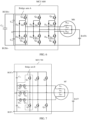
- the structure of the powertrain may alternatively be specifically implemented as a structure of a powertrain shown in FIG. 4 .
- the powertrain provided in this embodiment of this application includes an MCU 400 and a motor M4.
- the MCU 400 includes two bridge arms, and the motor M4 includes two motor windings (for example, motor windings N U 4 and N V 4 ) corresponding to the two bridge arms.
- a collector of a switch transistor Q 41 and a collector of a switch transistor Q 43 are connected to a positive bus BUS4+; an emitter of a switch transistor Q 42 and an emitter of a switch transistor Q 44 are connected to a negative bus BUS4-; an emitter of the switch transistor Q 41 and a collector of the switch transistor Q 42 are connected to one end of the motor winding N U 4 ; and an emitter of the switch transistor Q 43 and a collector of the switch transistor Q 44 are connected to one end of the motor winding N V 4 .
- the other end of the motor winding N U 4 and the other end of the motor winding N V 4 are connected to one end of a power battery BAT4, and the other end of the power battery BAT4 is connected to the negative bus BUS4-.
- the powertrain further includes a bus capacitor unit (for example, a capacitor C 41 ) connected between the positive bus BUS4+ and the negative bus BUS4-.
- a bus capacitor unit for example, a capacitor C 41
- the motor included in the powertrain provided in this embodiment of this application is a two-phase alternating current motor, and the powertrain in FIG. 3 includes a three-phase alternating current motor. Therefore, two bridge arms are correspondingly disposed in the MCU provided in this embodiment of this application.
- the power battery in this embodiment of this application is also connected to the motor windings, and charging and discharging of the power battery may also be implemented by reusing the motor windings and the bridge arms, so that a bi-directional DC/DC converter for charging and discharging the power battery is saved, and production costs of the powertrain are reduced.
- the structure of the powertrain may alternatively be specifically implemented as a structure of a powertrain shown in FIG. 5 .
- the powertrain provided in this embodiment of this application includes an MCU 500 and a motor M5.
- the MCU 500 includes four bridge arms, and the motor M5 includes four motor windings (for example, motor windings N U 5 , N V 5 , N W 5 , and N X 5 ) corresponding to the four bridge arms.
- a collector of a switch transistor Q 31 , a collector of a switch transistor Q 53 , a collector of a switch transistor Q 55 , and a collector of a switch transistor Q 57 are connected to a positive bus BUS5+; and an emitter of a switch transistor Q 52 , an emitter of a switch transistor Q 54 , an emitter of a switch transistor Q 56 , and an emitter of a switch transistor Q 58 are connected to a negative bus BUSS-.
- An emitter of the switch transistor Q 51 and a collector of the switch transistor Q 52 are connected to one end of the motor winding N U 5
- an emitter of the switch transistor Q 53 and a collector of the switch transistor Q 54 are connected to one end of the motor winding N V 5
- an emitter of the switch transistor Q 55 and a collector of the switch transistor Q 56 are connected to one end of the motor winding N W 5
- an emitter of the switch transistor Q 57 and a collector of the switch transistor Q 58 are connected to one end of the motor winding N X 5 .
- the other end of the motor winding N U 5 , the other end of the motor winding N V 5 , the other end of the motor winding N W 5 , and the other end of the motor winding N X 5 are connected to one end of a power battery BAT5, and the other end of the power battery BAT5 is connected to the negative bus BUSS-.
- the powertrain further includes a bus capacitor unit (for example, a capacitor C 51 ) connected between the positive bus BUSS+ and the negative bus BUSS-.
- a bus capacitor unit for example, a capacitor C 51
- the motor included in the powertrain provided in this embodiment of this application is a four-phase alternating current motor, and four bridge arms are correspondingly disposed in the MCU.
- the power battery in this embodiment of this application is also connected to the motor windings, and charging and discharging of the power battery may also be implemented by reusing the motor windings and the bridge arms, so that a bi-directional DC/DC converter for charging and discharging the power battery is saved, and production costs of the powertrain are reduced.
- the motor in the powertrain may be a two-phase alternating current motor, a three-phase alternating current motor, a four-phase alternating current motor, or the like.
- a specific implementation type of the motor is not limited in this application. Therefore, the structure of the powertrain may also be adaptively changed based on different motor types. For example, a quantity of bridge arms is changed. In other words, the powertrain provided in this application may further specifically include five bridge arms, six bridge arms, or the like.
- the bridge arm included in the MCU shown in FIG. 3 to FIG. 5 is a bridge arm that outputs two levels.
- a type of the bridge arm may also be changed to obtain a bridge arm that outputs a plurality of levels, so as to obtain a structure of a different powertrain.
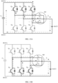
- FIG. 6 is still another schematic diagram of a structure of a powertrain according to an embodiment of this application.
- the powertrain provided in this embodiment of this application includes an MCU 600 and a motor M6.
- the motor M6 is specifically implemented as a three-phase alternating current motor.
- the MCU 600 includes three bridge arms A, and the motor M6 includes three motor windings (for example, motor windings N U 6 , N V 6 , and N W 6 ) corresponding to the three bridge arms A. It can be learned that, a type of the three bridge arms A included in the MCU 600 is different from that of the bridge arms included in FIG. 3 to FIG. 5 .
- the bridge arm A includes a first end, a second end, and a third end.
- the bridge arm A may output three levels.
- Each bridge arm A includes two switch units connected in series and two diodes respectively connected to the two switch units. Two ends that are obtained after the two switch units are connected in series are respectively the first end and the second end of the bridge arm A.
- the first end of the bridge arm A is connected to a positive bus BUS6+, and the second end of the bridge arm A is connected to a negative bus BUS6-.
- a midpoint of the bridge arm A is a series connection point of the two switch units, and is connected to a corresponding motor winding.
- a connection point of the two diodes in the bridge arm A is the third end of the bridge arm A, and the third end of the bridge arm A is connected to a neutral point O of the positive bus BUS6+ and the negative bus BUS6-. It may be understood that a voltage at the neutral point O is a half of a voltage between the positive bus BUS6+ and the negative bus BUS6-.
- one switch unit includes two switches connected in series.
- one switch unit includes a switch transistor Q 61 and a switch transistor Q 62
- the other switch unit includes a switch transistor Q 63 and a switch transistor Q 64 . Therefore, the first end of the bridge arm A is a collector of the switch transistor Q 61 .
- the collector of the switch transistor Q 61 is connected to the positive bus BUS6+.
- An emitter of the switch transistor Q 61 is connected to a collector of the switch transistor Q 62 , and a connection point between an emitter of the switch transistor Q 62 and a collector of the switch transistor Q 63 is the midpoint of the bridge arm A.
- the emitter of the switch transistor Q 62 and the collector of the switch transistor Q 63 are connected to one end of the motor winding N U 6 .
- An emitter of the switch transistor Q 63 is connected to a collector of the switch transistor Q 64 .
- the second end of the bridge arm A is an emitter of the switch transistor Q 64 .
- the emitter of the switch transistor Q 64 is connected to the negative bus BUS6-.
- a cathode of a diode D 61 is connected to the emitter of the switch transistor Q 61 and the collector of the switch transistor Q 62 .
- a connection point between an anode of the diode D 61 and a cathode of a diode D 62 is the third end of the bridge arm A.
- the anode of the diode D 61 and the cathode of the diode D 62 are connected to the neutral point O of the positive bus BUS6+ and the negative bus BUS6-, and an anode of the diode D 62 is connected to the emitter of the switch transistor Q 63 and the collector of the switch transistor Q 64 .
- a collector of a switch transistor Q 65 is connected to the positive bus BUS6+, an emitter of the switch transistor Q 65 is connected to a collector of a switch transistor Q 66 , an emitter of the switch transistor Q 66 and a collector of a switch transistor Q 67 are connected to one end of the motor winding N V 6 , an emitter of the switch transistor Q 67 is connected to a collector of a switch transistor Q 68 , and an emitter of the switch transistor Q 68 is connected to the negative bus BUS6-.
- a cathode of a diode D 63 is connected to the emitter of the switch transistor Q 65 and the collector of the switch transistor Q 66 , an anode of the diode D 63 and a cathode of a diode D 64 are connected to the neutral point O of the positive bus BUS6+ and the negative bus BUS6-, and an anode of the diode D 64 is connected to the emitter of the switch transistor Q 67 and the collector of the switch transistor Q 68 .
- a collector of a switch transistor Q 69 is connected to the positive bus BUS6+, an emitter of the switch transistor Q 69 is connected to a collector of a switch transistor Q 610 , an emitter of the switch transistor Q 610 and a collector of a switch transistor Q 611 are connected to one end of the motor winding N W 6 , an emitter of the switch transistor Q 611 is connected to a collector of the switch transistor Q 612 , and an emitter of the switch transistor Q 612 is connected to the negative bus BUS6-.
- a cathode of a diode D 65 is connected to the emitter of the switch transistor Q 69 and the collector of the switch transistor Q 610 , an anode of the diode D 65 and a cathode of a diode D 66 are connected to the neutral point O of the positive bus BUS6+ and the negative bus BUS6-, and an anode of the diode D 66 is connected to the emitter of the switch transistor Q 611 and the collector of the switch transistor Q 612 .
- the other end of the motor winding N U 6 , the other end of the motor winding N V 6 , and the other end of the motor winding N W 6 are connected to one end of a power battery BAT6, and the other end of the power battery B.AT6 is connected to the negative bus BUS6-.
- the powertrain further includes a bus capacitor unit (for example, capacitors C 61 , C 62 , and C 63 ) connected between the positive bus BUS6+ and the negative bus BUS6-.
- a bus capacitor unit for example, capacitors C 61 , C 62 , and C 63
- the capacitor C 62 and the capacitor C 63 are connected in series between the positive bus BUS6+ and the negative bus BUS6-, and a series connection point between the capacitor C 62 and the capacitor C 63 is the neutral point O.
- the three bridge arms A included in the MCU provided in this embodiment of this application output three levels.
- the powertrain may also implement charging and discharging of the power battery by reusing the motor windings and the bridge arms, so that a bi-directional DC/DC converter for charging and discharging the power battery is saved, and production costs of the powertrain are reduced.
- FIG. 7 is still another schematic diagram of a structure of a powertrain according to an embodiment of this application.
- the powertrain provided in this embodiment of this application includes an MCU 700 and a motor M7.
- the motor M7 is specifically implemented as a three-phase alternating current motor.
- the MCU 700 includes three bridge arms B, and the motor M7 includes three motor windings (for example, motor windings N U 7 , N V 7 , and N W 7 ) corresponding to the three bridge arms B.
- the bridge arm B includes a first end, a second end, and a third end, and the bridge arm B may also output three levels.
- Each bridge arm B includes a vertical bridge arm and a horizontal bridge arm, and the horizontal bridge arm and the vertical bridge arm each include two switch units connected in series.
- a midpoint of the vertical bridge arm is a midpoint of the bridge arm B, two ends that are obtained after the two switch units are connected in series in the vertical bridge arm are respectively the first end and the second end of the bridge arm B, one end of the two switch units connected in series in the horizontal bridge arm is connected to the midpoint of the bridge arm B, and the other end is the third end of the bridge arm B.
- one switch unit includes one switch
- the vertical bridge arm includes a switch transistor Q 71 and a switch transistor Q 72
- the horizontal bridge arm includes a switch transistor Q 73 and a switch transistor Q 74 . Therefore, the first end of the bridge arm B is a collector of the switch transistor Q 71 .
- the collector of the switch transistor Q 71 is connected to a positive bus BUS7+.
- a connection point between an emitter of the switch transistor Q 71 and a collector of the switch transistor Q 72 is the midpoint of the bridge arm B.
- the emitter of the switch transistor Q 71 and the collector of the switch transistor Q 72 are connected to one end of the motor winding N U 7 and a collector of the switch transistor Q 74 .
- An emitter of the switch transistor Q 74 is connected to an emitter of the switch transistor Q 73 .
- the third end of the bridge arm B is a collector of the switch transistor Q 73 .
- the collector of the switch transistor Q 73 is connected to a neutral point O1 of the positive bus BUS7+ and a negative bus BUS7-.
- a collector of a switch transistor Q 75 is connected to the positive bus BUS7+
- an emitter of the switch transistor Q 75 and a collector of a switch transistor Q 76 are connected to one end of the motor winding N V 7 and a collector of a switch transistor Q 78
- an emitter of the switch transistor Q 78 is connected to an emitter of a switch transistor Q 77
- a collector of the switch transistor Q 77 is connected to the neutral point O1 of the positive bus BUS7+ and the negative bus BUS7-.
- a collector of a switch transistor Q 79 is connected to the positive bus BUS7+, an emitter of the switch transistor Q 79 and a collector of a switch transistor Q 710 are connected to one end of the motor winding N W 7 and a collector of a switch transistor Q 712 , an emitter of the switch transistor Q 712 is connected to an emitter of a switch transistor Q 711 , and a collector of the switch transistor Q 711 is connected to the neutral point O1 of the positive bus BUS7+ and the negative bus BUS7-.
- the other end of the motor winding N U 7 , the other end of the motor winding N V 7 , and the other end of the motor winding N W 7 are connected to one end of a power battery BAT7, and the other end of the power battery BAT7 is connected to the negative bus BUS7-.
- the powertrain further includes a bus capacitor unit (for example, capacitors C 71 and C 72 ) connected between the positive bus BUS7+ and the negative bus BUS7-.
- a bus capacitor unit for example, capacitors C 71 and C 72
- the capacitor C 71 and the capacitor C 72 are connected in series between the positive bus BUS7+ and the negative bus BUS7-, and a series connection point between the capacitor C 71 and the capacitor C 72 is the neutral point O1.
- this embodiment of this application provides another bridge arm B that can output three levels.
- the powertrain may also implement charging and discharging of the power battery by reusing the motor windings and the bridge arms, so that a bi-directional DC/DC converter for charging and discharging the power battery is saved, and production costs of the powertrain are reduced.
- the bridge arm may be specifically implemented as another multi-level bridge arm different from the bridge arms that output two levels and three levels, for example, a multi-level bridge arm such as a four-level bridge arm or a five-level bridge arm, provided that bridge arms and motor windings may implement functions of both a DC/AC converter and a DC/DC converter.
- a quantity and a type of the bridge arms in the MCU are not limited in this embodiment of this application.
- the MCU includes three bridge arms and each bridge arm outputs two levels.
- the structure of the powertrain shown in FIG. 3 is used as an example.
- a powertrain shown in FIG. 8 may be obtained by adding an integrated power generation module to the powertrain shown in FIG. 3 .
- the powertrain provided in this embodiment of this application further includes a power generation module in addition to the MCU 300 and the motor M3 described with reference to FIG. 3 .
- the power generation module includes a generator control unit (Generator Control Unit, GCU) 801 and a generator M8.
- GCU Generator Control Unit
- the MCU 300, the motor M3, the GCU 801, and the generator M8 may be all integrated in the powertrain.
- the MCU 300 and the motor M3 may be integrated in the powertrain, and the GCU 801 and the generator M8 may be separately disposed.
- an input end of the GCU 801 is connected to the generator M8, and an output end of the GCU 801 is connected between the positive bus BUS3+ and the negative bus BUS3-.
- the GCU 801 may convert an alternating current output by the generator M8 into a direct current, and output the direct current between the positive bus BUS3+ and the negative bus BUS3-.
- electrical energy generated by the generator M8 may be provided for the power battery BAT3 and the motor M3; or electrical energy generated by the generator M8 and electrical energy generated by discharging of the power battery BAT3 are jointly provided for the motor M3.
- the powertrain shown in FIG. 8 further includes a GCU and a generator, and the technical effect of the embodiment described in FIG. 3 can still be implemented.
- a bi-directional DC/DC converter for charging and discharging a power battery can be saved, production costs of the powertrain can be reduced, and the powertrain has a simple structure and a simple power distribution structure.
- FIG. 9 is a schematic diagram of a waveform according to an embodiment of this application.
- a controller may determine, based on a working parameter of a motor and a bus voltage, a second modulation signal of each bridge arm, for example, a second modulation signal V U 32 , a second modulation signal V V 32 , and a second modulation signal V W 32 .
- the bus voltage is specifically a voltage between the positive bus BUS3+ and the negative bus BUS3-.
- the working parameter of the motor may be preset, and the working parameter of the motor includes at least one of an input voltage and an input current of the motor and a motor rotational speed.
- the input voltage of the motor may be specifically implemented as the bus voltage, and the bus voltage may be determined by using a working parameter of the generator and an AC/DC converter.
- controller determines the second modulation signal based on the working parameter of the motor and the bus voltage, refer to an existing control manner of a driving motor. Details are not described herein.
- an MCU includes the controller and N bridge arms, where N is greater than or equal to 2.
- the controller may be, for example, a central processing unit (central processing unit, CPU), another general purpose processor, a digital signal processor (digital signal processor, DSP), an application-specific integrated circuit (application specific integrated circuit, ASIC), a field programmable gate array (field-programmable gate array, FPGA) or another programmable logic device, a discrete gate or transistor logic device, or a discrete hardware component.
- the controller compares the second modulation signal V U 32 with a preset reference signal.
- the preset reference signal is a triangular wave, and an amplitude and a frequency of the preset reference signal are preset.
- the controller when the second modulation signal V U 32 is greater than the preset reference signal, the controller generates a high level; or when the second modulation signal V U 32 is less than the preset reference signal, the controller generates a low level.
- the controller may generate, based on a result of comparison between the second modulation signal V U 32 and the preset reference signal, a PWM_ Q 31 signal prior to a moment t0.
- the controller may generate, based on a result of comparison between the second modulation signal V V 32 and the preset reference signal, a PWM_ Q 33 signal prior to the moment t0; and the controller may generate, based on a result of comparison between the second modulation signal V W 32 and the preset reference signal, a PWM_ Q 35 signal prior to the moment t0.
- the controller sends the PWM_ Q 31 signal prior to the moment t0 to the switch transistor Q 31 , sends the PWM_ Q 33 signal prior to the moment t0 to the switch transistor Q 33 , and sends the PWM_ Q 35 signal prior to the moment t0 to the switch transistor Q 35 .
- a sum of currents of the three motor windings of the motor M3 is zero, and the motor M3 outputs torque.
- the switch transistor Q 31 , the switch transistor Q 33 , and the switch transistor Q 35 are turned off, and the switch transistor Q 32 , the switch transistor Q 34 , and the switch transistor Q 36 are turned on.
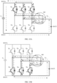
- a circuit status shown in FIG. 10 may be formed for the powertrain shown in FIG. 3 .
- a current flows in from the motor winding N U 3 , and flows out from the motor winding N V 3 and the motor winding N W 3 .
- I U 3 + I V 3 + I W 3 0.
- the motor M3 outputs torque to drive a hybrid electric vehicle.
- the current loop shown in FIG. 10 should be understood as an example, and the current flowing into the motor winding N U 3 may be provided by at least one of the generator and the power battery BAT3.
- Signals of the controller for controlling two switch transistors in a same bridge arm are complementary.
- a signal sent by the controller to the switch transistor Q 32 is complementary to the PWM_ Q 31 signal
- a signal sent by the controller to the switch transistor Q 34 is complementary to the PWM_ Q 33 signal
- a signal sent by the controller to the switch transistor Q 36 is complementary to the PWM_ Q 35 signal.
- the controller may determine at least one first bridge arm from the three bridge arms, and add a preset target value V 1 to a second modulation signal of each first bridge arm, to obtain a first modulation signal of each first bridge arm.
- the preset target value V 1 is determined by the controller based on a voltage of the power battery BAT3 and the bus voltage.
- the preset target value V 1 is a ratio of the voltage of the power battery BAT3 to the bus voltage.
- FIG. 9 an example in which the controller determines one first bridge arm from the three bridge arms is used, and specifically, a bridge arm formed by connecting the switch transistor Q 31 and the switch transistor Q 32 in series is the first bridge arm.
- the preset target value V 1 is used as a positive bias voltage, and the controller adds the preset target value V 1 to the second modulation signal V U 32 , to obtain the first modulation signal V U 31 .
- the controller compares the first modulation signal V U 31 with the preset reference signal, to generate a PWM_ Q 31 signal (that is, a first PWM signal of a first bridge arm on which the switch transistor Q 31 is located) subsequent to the moment t0. It can be learned that a duty cycle of the PWM_ Q 31 signal subsequent to the moment t0 is greater than a duty cycle of the PWM_ Q 31 signal subsequent to the moment t0. To be specific, the controller adds the preset target value V 1 to the second modulation signal V U 32 , and specifically, a duty cycle of a control signal of the switch transistor Q 31 is increased.
- modulation signals prior to the moment t0 are still used.
- the second modulation signal V V 32 and the second modulation signal V W 32 are still used. Therefore, duty cycles of the PWM_ Q 33 signal and the PWM_ Q 35 signal prior to and subsequent to the moment t0 do not change.
- the controller sends the PWM_ Q 31 signal subsequent to the moment t0 to the switch transistor Q 31 , sends the PWM_ Q 33 signal subsequent to the moment t0 to the switch transistor Q 33 , and sends the PWM_ Q 35 signal subsequent to the moment t0 to the switch transistor Q 35 .
- the capacitor C 31 charges the power battery BAT3 through the motor winding N U 3 , charges the power battery BAT3 through the motor winding N V 3 , and charges the power battery BAT3 through the motor winding N W 3 .
- the motor M3 outputs torque.
- energy stored in the capacitor C 31 may be provided by a generator.
- a GCU connected to the generator converts a voltage output by the generator to obtain a first voltage, specifically, converts an alternating current output by the generator into a direct current, and then the MCU converts the first voltage to drive the motor M3 to output torque.
- the first bridge arm and the motor winding connected to the first bridge arm may ensure a function of an electric drive system of the motor, namely, may implement a function of a DC/AC converter.
- the first bridge arm and the motor winding connected to the first bridge arm may implement a function of a DC/DC converter, and specifically implement a voltage step-down function of the DC/DC converter, namely, implement a function of a buck converter.
- the generator drives the motor, and the generator charges the power battery.
- the PWM_ Q 31 signal, the PWM_ Q 33 signal, and the PWM_ Q 35 are all at a high level.
- the switch transistor Q 31 , the switch transistor Q 33 , and the switch transistor Q 35 are turned on, and the switch transistor Q 32 , the switch transistor Q 34 , and the switch transistor Q 36 are turned off.
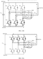
- a circuit status shown in FIG. 11A may be formed for the powertrain. As shown in FIG. 11A , it is assumed that inductive reactances of the three motor windings are the same.
- a current flowing through the motor winding N U 3 is I U 3 + I C /3
- a current flowing through the motor winding N V 3 is I V 3 + I C /3
- the motor M3 outputs torque, and the three motor windings are in an energy storage stage.
- the PWM_ Q 31 signal, the PWM_ Q 33 signal, and the PWM_ Q 35 signal are all at a low level.
- the switch transistor Q 31 , the switch transistor Q 33 , and the switch transistor Q 35 are turned off, and the switch transistor Q 32 , the switch transistor Q 34 , and the switch transistor Q 36 are turned on.
- a circuit status shown in FIG. 11B may be formed for the powertrain. As shown in FIG. 11B , the currents of the motor windings cannot change abruptly, and the currents flowing through the three motor windings are still the currents that flow in the circuit status shown in FIG. 11A .
- the current flowing through the motor winding N U 3 is I U 3 + I C /3
- the current flowing through the motor winding N V 3 is I V 3 + I C /3
- the motor M3 outputs torque.
- the motor winding N U 3 charges the power battery BAT3
- the motor winding N V 3 charges the power battery BAT3
- the motor winding N W 3 charges the power battery BAT3.
- a current on each motor winding is provided by the capacitor C 31 .
- the capacitor C 31 charges the power battery BAT3 through the motor winding connected to the first bridge arm, where a charging current is I C .
- the controller may directly send the PWM_ Q 31 signal, the PWM_ Q 33 signal, and the PWM_ Q 35 signal that are subsequent to the moment t0.
- the PWM_ Q 31 signal, the PWM_ Q 33 signal, and the PWM_ Q 35 signal that are prior to the moment t0 are directly sent.
- signals prior to the moment t0 and signals subsequent to the moment t0 may exist relatively independently.
- the controller may specifically determine, depending on a battery level of a power battery, a control signal to be sent to each bridge arm. For example, if the controller detects that a battery level of the power battery BAT3 is lower than a preset charging threshold, the controller sends the PWM_ Q 31 signal subsequent to the moment t0 to the switch transistor Q 31 , sends the PWM_ Q 33 signal subsequent to the moment t0 to the switch transistor Q 33 , and sends the PWM_ Q 35 signal subsequent to the moment t0 to the switch transistor Q 35 .
- the controller When the battery level of the power battery BAT3 is greater than or equal to the preset charging threshold, the controller sends the PWM_ Q 31 signal prior to the moment t0 to the switch transistor Q 31 , sends the PWM_ Q 33 signal prior to the moment t0 to the switch transistor Q 33 , and sends the PWM_ Q 35 signal prior to the moment t0 to the switch transistor Q 35 .
- the controller may send the PWM_ Q 31 signal subsequent to the moment t0 to the switch transistor Q 31 , send the PWM_ Q 33 signal subsequent to the moment t0 to the switch transistor Q 33 , and send the PWM_ Q 35 signal subsequent to the moment t0 to the switch transistor Q 35 .
- the preset target value V 1 is added to the second modulation signal of one first bridge arm.
- one of the three bridge arms is reused for charging control of the power battery.
- a time for turning on and turning off the switch transistors corresponding to the first bridge arm is changed, to implement output torque of the motor and charging of the power battery.
- the powertrain may implement both a function of the DC/AC converter and a function of the buck converter.
- FIG. 12 is a schematic diagram of still another waveform according to an embodiment of this application.
- a controller may determine a second modulation signal, for example, a second modulation signal V U 32 ' , a second modulation signal V V 32 ' , and a second modulation signal V W 32 ' , of each bridge arm based on a working parameter of a motor and a bus voltage.
- the controller generates, based on a result of comparison of the second modulation signal V U 32 ' and a preset reference signal, a PWM_ Q 31 ' signal prior to a moment t0'.
- the controller generates, based on a result of comparison of the second modulation signal V V 32 ' and the preset reference signal, a PWM_ Q 33 ' signal prior to the moment t0'.
- the controller generates, based on a result of comparison of the second modulation signal V W 32 ' and the preset reference signal, a PWM_ Q 35 ' signal prior to the moment t0'.
- the controller sends the PWM_ Q 31 ' signal prior to the moment t0' to the switch transistors Q 31 , sends the PWM_ Q 33 ' signal prior to the moment t0' to the switch transistors Q 33 , and sends the PWM_ Q 35 ' signal prior to the moment t0' to the switch transistors Q 35 .
- the controller may use the three bridge arms as three first bridge arms respectively; therefore, the controller adds a preset target value V 1 to a second modulation signal of each first bridge arm, so as to obtain a first modulation signal of each first bridge arm.
- the controller adds the preset target value V 1 to the second modulation signal V U 32 ' to obtain a first modulation signal V U 31 ', adds the preset target value V 1 to the second modulation signal V V 32 ' to obtain a first modulation signal V V 31 ', and adds the preset target value V 1 to the second modulation signal V W 32 ' to obtain a first modulation signal V W 31 '.
- the controller compares the first modulation signal V U 31 ' with the preset reference signal, to generate a PWM_ Q 31 ' signal (that is, a first PWM signal of a first bridge arm on which the switch transistor Q 31 is located) subsequent to the moment t0'. It can be learned that, a duty cycle of the PWM_ Q 31 ' signal subsequent to the moment t0' is greater than a duty cycle of the PWM_ Q 31 ' signal prior to the moment t0'.
- the controller compares the first modulation signal V V 31 ' with the preset reference signal, to generate a PWM_ Q 33 ' signal (that is, a first PWM signal of a first bridge arm on which the switch transistor Q 33 is located) subsequent to the moment t0', where a duty cycle of the PWM_ Q 33 ' signal subsequent to the moment t0' is greater than a duty cycle of the PWM_ Q 33 ' signal prior to the moment t0'.
- a PWM_ Q 33 ' signal that is, a first PWM signal of a first bridge arm on which the switch transistor Q 33 is located
- the controller compares the first modulation signal V W 31 ' with the preset reference signal, to generate a PWM_ Q 35 ' signal (that is, a first PWM signal of a first bridge arm on which the switch transistor Q 35 is located) subsequent to the moment t0', where a duty cycle of the PWM_ Q 35 ' signal subsequent to the moment t0' is greater than a duty cycle of the PWM_ Q 35 ' signal prior to the moment t0'.
- a PWM_ Q 35 ' signal that is, a first PWM signal of a first bridge arm on which the switch transistor Q 35 is located
- the controller sends the PWM_ Q 31 ' signal subsequent to the moment t0' to the switch transistors Q 31 , sends the PWM_ Q 33 ' signal subsequent to the moment t0' to the switch transistors Q 33 , and sends the PWM_ Q 35 ' signal subsequent to the moment t0' to the switch transistors Q 35 .
- the motor M3 outputs torque, and the power battery BAT3 is charged.
- the circuit status shown in FIG. 11A may still be formed for the powertrain; and in a time period from a moment t2' to a moment t3', the circuit status shown in FIG. 11B may still be formed for the powertrain. Therefore, for a circuit status of the powertrain, reference may be made to the descriptions in FIG. 11A and FIG. 11B . Details are not described herein again.
- the schematic diagram of the waveform shown in FIG. 12 is used by the controller to specifically reuse three bridge arms for charging control of the power battery.
- the preset target value V 1 is added to the second modulation signal of each of the three bridge arms, and the effect of embodiments described above with reference to FIG. 9 to FIG. 11B can still be implemented.
- the three bridge arms are reused, so that current equalization can be performed among the three bridge arms.
- the preset target value V 1 may be added to second modulation signals of two of the three bridge arms (this is not shown in the figure).
- the two bridge arms may be reused for charging control of the power battery.
- the circuit statuses in FIG. 11A and FIG. 11B may still be formed, the motor M3 outputs torque, and the power battery BAT3 is in a charging state.
- the motor may not output torque, and the power battery is in a charging state.
- the controller may determine at least one second bridge arm from the three bridge arms of the MCU, and determine a second PWM signal of each second bridge arm based on the bus voltage and a voltage of the power battery BAT3.
- controller determines the second PWM signal based on the bus voltage and the voltage of the power battery BAT3
- reference may be made to an existing manner of determining a control signal of a switch transistor in a buck converter. Details are not described herein again.
- That the capacitor C 31 charges the power battery BAT3 may be divided into an energy storage phase of motor windings and a power battery charging phase.
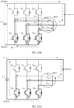
- FIG. 13A and FIG. 13B an example in which the three bridge arms are respectively used as three second bridge arms is used.
- the switch transistor Q 31 , the switch transistor Q 33 , and the switch transistor Q 35 are turned on, and the switch transistor Q 32 , the switch transistor Q 34 , and the switch transistor Q 36 are turned off.
- the motor winding N U 3 , the motor winding N V 3 , and the motor winding N W 3 are in an energy storage stage.
- the circuit status shown in FIG. 11A may be understood as a combination of the circuit status shown in FIG. 13A and the circuit status shown in FIG. 10 .
- the capacitor C 31 charges the power battery BAT3 through the motor winding N U 3
- the capacitor C 31 charges the power battery B.AT3 through the motor winding N V 3
- the capacitor C 31 charges the power battery BAT3 through the motor winding N W 3 . Therefore, a charging current of the power battery BAT3 may be I C .
- energy stored in the capacitor C 31 may be provided by a generator.
- a GCU connected to the generator converts a voltage output by the generator to obtain a third voltage, and then the MCU converts the third voltage to charge the power battery BAT3. In conclusion, the generator charges the power battery.
- the circuit status shown in FIG. 11B may be understood as a combination of the circuit status shown in FIG. 13B and the circuit status shown in FIG. 10 .
- a current flowing through each motor winding is a sum of a current flowing through the motor winding when the motor outputs torque and a charging current of the power battery.
- circuit statuses shown in FIG. 13A and FIG. 13B should be understood as an example.
- a function of a buck converter can be implemented by controlling only one or two of the three bridge arms.
- FIG. 14 is a schematic diagram of still another waveform according to an embodiment of this application.
- a controller may determine a second modulation signal, for example, a second modulation signal V U 3 B , a second modulation signal V V 3 B , and a second modulation signal V W 3 B , of each bridge arm based on a working parameter of a motor, a bus voltage, and a voltage of a power battery.
- the controller generates, based on a result of comparison of the second modulation signal V U 3 B and a preset reference signal, a PWM1_ Q 31 signal prior to a moment t4.
- the controller may generate, based on a result of comparison of the second modulation signal V V 3 B and the preset reference signal, a PWM1_ Q 33 signal prior to the moment t4.
- the controller may generate, based on a result of comparison of the second modulation signal V W 3 B and the preset reference signal, a PWM1_ Q 35 signal prior to the moment t4.
- the controller sends the PWM1_ Q 31 signal prior to the moment t4 to the switch transistor Q 31 , sends the PWM1_ Q 33 signal prior to the moment t4 to the switch transistor Q 33 , and sends the PWM1_ Q 35 signal prior to the moment t4 to the switch transistor Q 35 .
- the power battery BAT3 in this embodiment of this application discharges, and the motor M3 outputs torque.
- the controller may determine at least one first bridge arm from the three bridge arms, and subtract a preset target value V 2 from a second modulation signal of each first bridge arm, to obtain a first modulation signal of each first bridge arm.
- the preset target value V 2 is determined by the controller based on a voltage of the power battery BAT3 and the bus voltage.
- the preset target value V 2 is a ratio of the voltage of the power battery BAT3 to the bus voltage.
- FIG. 14 an example in which the three bridge arms include one first bridge arm is used, and specifically, a bridge arm formed by connecting the switch transistor Q 31 and the switch transistor Q 32 in series is the first bridge arm.
- the controller compares the first modulation signal V U 3 A with the preset reference signal, to generate a PWM1_ Q 31 signal (that is, a first PWM signal of a first bridge arm on which the switch transistor Q 31 is located) subsequent to the moment t4. It can be learned that, a duty cycle of the PWM1_ Q 31 signal subsequent to the moment t4 is less than a duty cycle of the PWM1_ Q 31 signal subsequent to the moment t4. To be specific, the controller subtracts the preset target value V 2 from the second modulation signal V U 3 B , and specifically, a duty cycle of a control signal of the switch transistor Q 31 is decreased.
- modulation signals prior to the moment t4 are still used.
- the second modulation signal V V 3 B and the second modulation signal V W 3 B are still used. Therefore, duty cycles of the PWM1_ Q 33 signal and the PWM1_ Q 35 signal prior to and subsequent to the moment t4 do not change.
- the controller sends the PWM1_ Q 31 signal subsequent to the moment t4 to the switch transistor Q 31 , sends the PWM1_ Q 33 signal subsequent to the moment t4 to the switch transistor Q 33 , and sends the PWM1_ Q 35 signal subsequent to the moment t4 to the switch transistor Q 35 .
- the motor M3 outputs torque
- the power battery BAT3 is in a discharging state.
- the power battery BAT3 and the bus capacitor unit (for example, the capacitor C 31 ) jointly provide a driving voltage for the motor M3.
- the first bridge arm and a motor winding corresponding to the first bridge arm may ensure a function of an electric drive system of the motor, namely, may implement a function of a DC/AC converter.
- the first bridge arm and the motor winding corresponding to the first bridge arm may implement a function of a DC/DC converter, and specifically implement a voltage step-up function in the DC/DC converter, namely, implement a function of a boost converter.
- the PWM1_ Q 31 signal, the PWM1_ Q 33 signal, and the PWM1_ Q 35 signal are all at a high level.
- the switch transistor Q 31 , the switch transistor Q 33 , and the switch transistor Q 35 are turned on, and the switch transistor Q 32 , the switch transistor Q 34 , and the switch transistor Q 36 are turned off.
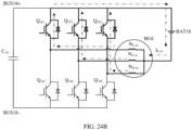
- a circuit status shown in FIG. 15A may be formed for the powertrain. As shown in FIG. 15A , it is assumed that inductive reactances of the three motor windings are the same.
- a current flowing through the motor winding N U 3 is I U 3 + I DC /3
- a current flowing through the motor winding N V 3 is I V 3 + I DC /3
- the motor M3 outputs torque.
- the power battery BAT3 discharges through the motor winding N U 3 , the motor winding N V 3 , and the motor winding N W 3 .
- the power battery BAT3 is in a discharging state, where a discharging current is I DC .
- a generator and the power battery drive the motor simultaneously.
- a GCU connected to the generator converts a voltage output by the generator to obtain a second voltage
- the MCU may drive, based on the second voltage and the voltage of the power battery, the motor to output torque.
- the PWM1_ Q 31 signal, the PWM1_ Q 33 signal, and the PWM1_ Q 35 signal are all at a low level.
- the switch transistor Q 31 , the switch transistor Q 33 , and the switch transistor Q 35 are turned off, and the switch transistor Q 32 , the switch transistor Q 34 , and the switch transistor Q 36 are turned on.
- a circuit status shown in FIG. 15B may be formed for the powertrain. As shown in FIG. 15B , the currents of the motor windings cannot change abruptly, and the currents flowing through the three motor windings are still the currents that flow in the circuit status shown in FIG. 15A .
- the current flowing through the motor winding N U 3 is I U 3 + I DC /3
- the current flowing through the motor winding N V 3 is I V 3 + I DC /3
- the motor M3 outputs torque, and the three motor windings are in an energy storage stage.
- the controller may directly send the PWM1_ Q 31 signal, the PWM1_ Q 33 signal, and the PWM1_ Q 35 signal that are subsequent to the moment t4.
- the PWM1_ Q 31 signal, the PWM1_ Q 33 signal, and the PWM1_ Q 35 signal that are prior to the moment t4 are directly sent.
- signals prior to the moment t4 and signals subsequent to the moment t4 may exist relatively independently.
- the controller may determine, based on a rotation speed of the motor and a battery level of the power battery, a control signal to be sent to each bridge arm. For example, if it is detected that the rotational speed of the motor is greater than a preset speed and the voltage at both ends of the power battery is greater than a preset discharging threshold, the controller sends the PWM1_ Q 31 signal subsequent to the moment t4 to the switch transistor Q 31 , sends the PWM1_ Q 33 signal subsequent to the moment t4 to the switch transistor Q 33 , and sends the PWM1_ Q 35 signal subsequent to the moment t4 to the switch transistor Q 35 .
- the preset target value V 2 is subtracted from the second modulation signal of one first bridge arm of the three bridge arms.
- one of the three bridge arms is reused for discharging control of the power battery.
- a time for turning on and turning off the switch transistors corresponding to the first bridge arm is changed, so that the motor outputs torque while the power battery discharges.
- the powertrain may implement both a function of the boost converter and a function of the DC/AC converter.
- FIG. 16 is a schematic diagram of still another waveform according to an embodiment of this application.
- a controller may determine a second modulation signal, for example, a second modulation signal V U 3 B ', a second modulation signal V V 3 B ', and a second modulation signal V W 3 B ', of each bridge arm based on a working parameter of a motor and a bus voltage.
- the controller generates, based on a result of comparison of the second modulation signal V U 3 B ' and a preset reference signal, a PWM1_ Q 31 ' signal prior to a moment t4'.
- the controller generates, based on a result of comparison of the second modulation signal V V 3 B ' and the preset reference signal, a PWM1_ Q 33 ' signal prior to the moment t4'.
- the controller generates, based on a result of comparison of the second modulation signal V W 3 B ' and the preset reference signal, a PWM1_ Q 35 ' signal prior to the moment t4'.
- the controller sends the PWM1_ Q 31 ' signal prior to the moment t4' to the switch transistors Q 31 , sends the PWM1_ Q 33 ' signal prior to the moment t4' to the switch transistors Q 33 , and sends the PWM1_ Q 35 ' signal prior to the moment t4' to the switch transistors Q 35 .
- the controller may use the three bridge arms as three first bridge arms respectively; therefore, the controller subtracts the preset target value V 2 from a second modulation signal of each first bridge arm, to obtain a first modulation signal of each first bridge arm.
- the controller subtracts the preset target value V 2 from the second modulation signal V U 3 B ' to obtain a first modulation signal V U 3 A ', subtracts the preset target value V 2 from the second modulation signal V V 3 B ' to obtain a first modulation signal V V 3 A ', and subtracts the preset target value V 2 from the second modulation signal V W 3 B ' to obtain a first modulation signal V W 3 A ' .
- the controller compares the first modulation signal V U 3 A ' with the preset reference signal, to generate a PWM1_ Q 31 ' signal (that is, a first PWM signal of a first bridge arm on which the switch transistor Q 31 is located) subsequent to the moment t4'. It can be learned that, a duty cycle of the PWM1_ Q 31 ' signal subsequent to the moment t4' is less than a duty cycle of the PWM1_ Q 31 ' signal prior to the moment t4'.
- the controller compares the first modulation signal V V 3 A ' with the preset reference signal, to generate a PWM1_ Q 33 ' signal (that is, a first PWM signal of a first bridge arm on which the switch transistor Q 33 is located) subsequent to the moment t4'.
- a duty cycle of the PWM1_ Q 33 ' signal subsequent to the moment t4' is less than a duty cycle of the PWM1_ Q 33 ' signal prior to the moment t4'.
- the controller compares the first modulation signal V W 3 A ' with the preset reference signal, to generate a PWM1_ Q 35 ' signal (that is, a first PWM signal of a first bridge arm on which the switch transistor Q 35 is located) subsequent to the moment t4'.
- a duty cycle of the PWM1_ Q 35 ' signal subsequent to the moment t4' is less than a duty cycle of the PWM1_ Q 35 ' signal prior to the moment t4'.
- the controller sends the PWM1_ Q 31 ' signal subsequent to the moment t4' to the switch transistors Q 31 , sends the PWM1_ Q 33 ' signal subsequent to the moment t4' to the switch transistors Q 33 , and sends the PWM1_ Q 35 ' signal subsequent to the moment t4' to the switch transistors Q 35 .
- the motor M3 outputs torque, and the power battery BAT3 is in a discharging state.
- the circuit status shown in FIG. 15A may still be formed for the powertrain; and in a time period from a moment t6' to a moment t7', the circuit status shown in FIG. 15B may still be formed for the powertrain. Therefore, for a circuit status of the powertrain, reference may be made to the descriptions in FIG. 15A and FIG. 15B . Details are not described herein again.
- the schematic diagram of the waveform shown in FIG. 16 is used by the controller to specifically reuse three bridge arms for discharging control of the power battery.
- the preset target value V 2 of the power battery is subtracted from the second modulation signal of each of the three bridge arms, and the effect of embodiments described above with reference to FIG. 14 to FIG. 15B can still be implemented.
- the three bridge arms are reused, so that current equalization can be performed among the three bridge arms.
- the preset target value V 2 may be subtracted from second modulation signals of two of the three bridge arms (this is not shown in the figure).
- the two bridge arms may be reused for discharging control of the power battery.
- circuit statuses in FIG. 15A and FIG. 15B may still be formed, the motor outputs torque, and the power battery BAT3 is in a discharging state.
- the motor may not output torque, and the power battery is in a discharging state.
- the power battery outputs a voltage between the positive bus BUS3+ and the negative bus BUS3-.
- the powertrain includes a generator.
- the power battery may provide power for the generator, and the generator drives an internal combustion engine to ignite in a rotation process, so that the generator is started to convert mechanical energy into electrical energy.
- the controller may determine at least one second bridge arm from the three bridge arms of the MCU, and determine a second PWM signal of each second bridge arm based on the bus voltage and a voltage of the power battery BAT3.
- controller determines the second PWM signal based on the bus voltage and the voltage of the power battery BAT3
- reference may be made to an existing manner of determining a control signal of a switch transistor in a boost converter. Details are not described herein again.
- the power battery BAT3 discharges.
- the power battery BAT3 outputs a voltage to a bus. That the power battery BAT3 outputs the voltage to the bus may be divided into an energy storage stage of motor windings and a power battery discharging stage.
- FIG. 17A and FIG. 17B an example in which the three bridge arms are respectively used as three second bridge arms is used.
- the switch transistor Q 31 , the switch transistor Q 33 , and the switch transistor Q 35 are turned on, and the switch transistor Q 32 , the switch transistor Q 34 , and the switch transistor Q 36 are turned off.
- the power battery BAT3 discharges through the motor winding N U 3
- the power battery BAT3 discharges through the motor winding N V 3
- the power battery BAT3 discharges through the motor winding N W 3 .
- the MCU converts a voltage of the power battery BAT3 to obtain a fourth voltage, and outputs the fourth voltage between the positive bus BUS3+ and the negative bus BUS3-.
- a GCU connected between the positive bus BUS3+ and the negative bus BUS3- may drive the generator based on the fourth voltage.
- the power battery discharges to drive the generator.
- circuit status shown in FIG. 15A may be understood as a combination of the circuit status shown in FIG. 17A and the circuit status shown in FIG. 10 .
- the switch transistor Q 31 , the switch transistor Q 33 , and the switch transistor Q 35 are turned off, and the switch transistor Q 32 , the switch transistor Q 34 , and the switch transistor Q 36 are turned on.
- the motor winding N U 3 , the motor winding N V 3 , and the motor winding N W 3 are in an energy storage stage.
- the circuit status shown in FIG. 15B may be understood as a combination of the circuit status shown in FIG. 17B and the circuit status shown in FIG. 10 .
- a current flowing through each motor winding is a sum of a current flowing through the motor winding when the motor outputs torque and a discharging current of the power battery.
- circuit statuses shown in FIG. 17A and FIG. 17B should be understood as an example.
- a function of a boost converter can be implemented by controlling only one or two of the three bridge arms.
- one end of the power battery BAT3 is a positive electrode and is connected to the motor windings, and the other end of the power battery BAT3 is a negative electrode and is connected to the negative bus BUS3-.
- one end of a power battery may be a negative electrode and is connected to motor windings, and the other end of the power battery may be a positive electrode and is connected to a positive bus.
- the powertrain provided in this embodiment of this application includes an MCU 1800 and a motor M 18. It can be learned that a difference between the powertrain in FIG. 18 and the powertrain shown with reference to FIG. 3 to FIG. 17B lies in that the other end of a power battery BAT18 is connected to a positive bus.
- a first end of each of the three bridge arms is connected to a positive bus BUS18+.
- a collector of a switch transistor Q 181 , a collector of a switch transistor Q 183 , and a collector of a switch transistor Q 185 are connected to the positive bus BUS18+.
- a second end of each bridge arm is connected to a negative bus BUS18-.
- an emitter of a switch transistor Q 182 , an emitter of a switch transistor Q 184 , and an emitter of a switch transistor Q 186 are connected to the negative bus BUS 18-.
- a midpoint of each bridge arm is connected to one end of one motor winding.
- an emitter of the switch transistor Q 181 and a collector of the switch transistor Q 182 are connected to one end of a motor winding N U 18
- an emitter of the switch transistor Q 183 and a collector of the switch transistor Q 184 are connected to one end of a motor winding N V 18
- an emitter of the switch transistor Q 185 and a collector of the switch transistor Q 186 are connected to one end of a motor winding N W 18 .
- the other end of the motor winding N U 18 , the other end of the motor winding N V 18 , and the other end of the motor winding N W 18 are connected to one end of the power battery BAT18, and the other end of the power battery BAT18 is connected to the positive bus BUS18+.
- the powertrain further includes a bus capacitor unit (for example, a capacitor C 181 ) connected between the positive bus BUS18+ and the negative bus BUS18-.
- a bus capacitor unit for example, a capacitor C 181
- a power generation module may be added to the powertrain shown in FIG. 18 , to obtain a powertrain shown in FIG. 19 .
- the powertrain in addition to the MCU 1800 and the motor M18 described with reference to FIG. 18 , the powertrain further includes a GCU 1901 and a generator M19.
- the MCU 1800, the motor M18, the GCU 1901, and the generator M19 may be all integrated in the powertrain.
- the MCU 1800 and the motor M18 may be integrated in the powertrain, and the GCU 1901 and the generator M19 may be separately disposed.
- an input end of the GCU 1901 is connected to the generator M19, and an output end of the GCU 1901 is connected between the positive bus BUS18+ and the negative bus BUS18-.
- the GCU 1901 may convert an alternating current output by the generator M19 into a direct current, and output the direct current between the positive bus BUS18+ and the negative bus BUS18-.
- a bus voltage between the positive bus BUS18+ and the negative bus BUS18- may be provided by the generator M19, or may be jointly provided by the power battery BAT18 and the generator M19.
- FIG. 9 the schematic diagrams of the waveforms shown in FIG. 9 , FIG. 12 , FIG. 14 , and FIG. 16 are still applicable to the structure of the powertrain in FIG. 18 and FIG. 19 .
- a controller sends a signal prior to the moment t0 shown in FIG. 9 to each bridge arm.
- the controller sends the PWM_ Q 31 signal prior to the moment t0 to the switch transistor Q 181 , sends the PWM_ Q 33 signal prior to the moment t0 to the switch transistor Q 183 , and sends the PWM_ Q 35 signal prior to the moment t0 to the switch transistor Q 185 .
- a sum of currents of the three motor windings of the motor M18 is zero, and the motor M18 outputs torque.
- a circuit status shown in FIG. 20 may be formed for the powertrain shown in FIG. 18 .
- a current of the motor M18 flows in from the motor winding N U 18 , and flows out from the motor winding N V 18 and the motor winding N W 18 .
- I U 18 + I V 18 + I W 18 0.
- the motor M18 outputs torque. In other words, the generator drives the motor M18.
- the controller may send a signal subsequent to the moment t0 shown in FIG. 9 to each bridge arm.
- the controller sends the PWM_ Q 31 signal subsequent to the moment t0 to the switch transistor Q 181 , sends the PWM_ Q 33 signal subsequent to the moment t0 to the switch transistor Q 183 , and sends the PWM_ Q 35 signal subsequent to the moment t0 to the switch transistor Q 185 .
- the motor M18 outputs torque
- the power battery BAT18 discharges.
- the generator and the power battery jointly drive the motor M18.
- the PWM_ Q 31 signal, the PWM_ Q 33 signal, and the PWM_ Q 35 signal are all at a high level.
- the switch transistor Q 181 , the switch transistor Q 183 , and the switch transistor Q 185 are turned on, and the switch transistor Q 182 , the switch transistor Q 184 , and the switch transistor Q 186 are turned off.
- a circuit status shown in FIG. 21A may be formed for the powertrain. As shown in FIG. 21A , it is assumed that inductive reactances of the three motor windings are the same.
- a current flowing through the motor winding N U 18 is I U 18 + I DC 18 /3
- a current flowing through the motor winding N V 18 is I V 18 + I DC 18 /3
- the motor M18 outputs torque, and the three motor windings are in an energy storage stage.
- the PWM_ Q 31 signal, the PWM_ Q 33 signal, and the PWM_ Q 35 signal are all at a low level.
- the switch transistor Q 181 , the switch transistor Q 183 , and the switch transistor Q 185 are turned off, and the switch transistor Q 182 , the switch transistor Q 184 , and the switch transistor Q 186 are turned on.
- a circuit status shown in FIG. 21B may be formed for the powertrain. As shown in FIG. 21B , the currents of the motor windings cannot change abruptly, and the currents flowing through the three motor windings are still the currents that flow in the circuit status shown in FIG. 21A .
- the current flowing through the motor winding N U 18 is I U 18 + I DC 18 /3
- the current flowing through the motor winding N V 18 is I V 18 + I DC 18 /3
- the motor M18 outputs torque.
- the power battery BAT18 discharges, where a discharging current is I DC 18 .
- the controller sends a signal subsequent to the moment t0' shown in FIG. 12 to each bridge arm.
- the controller sends the PWM_ Q 31 ' signal subsequent to the moment t0' to the switch transistor Q 181 , sends the PWM_ Q 33 ' signal subsequent to the moment t0' to the switch transistor Q 183 , and sends the PWM_ Q 35 ' signal subsequent to the moment t0' to the switch transistor Q 185 .
- the circuit status shown in FIG. 21A may still be formed for the powertrain; and in a time period from the moment t1' to the moment t2', the circuit status shown in FIG. 21B may still be formed for the powertrain. Therefore, for a circuit status of the powertrain, reference may be made to the descriptions in FIG. 21A and FIG. 21B . Details are not described herein again.
- the controller may determine at least one second bridge arm from the three bridge arms of the MCU, and determine a second PWM signal of each second bridge arm based on a bus voltage and a voltage of the power battery BAT18.
- the controller determines the second PWM signal based on the bus voltage and the voltage of the power battery BAT18.
- reference may be made to an existing manner of determining a control signal of a switch transistor in a boost converter.
- That the capacitor C 181 charges the power battery BAT18 may be divided into an energy storage phase of motor windings and a power battery charging phase.
- FIG. 22A and FIG. 22B an example in which the three bridge arms are respectively used as three second bridge arms is used.
- the switch transistor Q 181 , the switch transistor Q 183 , and the switch transistor Q 185 are turned on, and the switch transistor Q 182 , the switch transistor Q 184 , and the switch transistor Q 186 are turned off.
- the motor winding N U 18 , the motor winding N V 18 , and the motor winding N W 18 are in an energy storage stage.
- the circuit status shown in FIG. 21A may be understood as a combination of the circuit status shown in FIG. 22A and the circuit status shown in FIG. 20 .
- the switch transistor Q 181 , the switch transistor Q 183 , and the switch transistor Q 185 are turned off, and the switch transistor Q 182 , the switch transistor Q 184 , and the switch transistor Q 186 are turned off.
- the power battery BAT18 provides a voltage for the capacitor C 181 by using the three motor windings, that is, outputs a voltage between the positive bus BUS18+ and the negative bus BUS18-, and the motor M18 is driven by the power battery BAT18.
- the circuit status shown in FIG. 21B may be understood as a combination of the circuit status shown in FIG. 22B and the circuit status shown in FIG. 20 .
- a current flowing through each generator winding is a sum of a current generated by the generator and a discharging current of the power battery.
- circuit statuses shown in FIG. 22A and FIG. 22B should be understood as an example.
- a function of a boost converter can be implemented by controlling only one or two of the three bridge arms.
- the controller sends a signal prior to the moment t4 shown in FIG. 14 to each bridge arm.
- the controller sends the PWM1_ Q 31 signal prior to the moment t4 to the switch transistor Q 181 , sends the PWM1_ Q 33 signal prior to the moment t4 to the switch transistor Q 183 , and sends the PWM1_ Q 35 signal prior to the moment t4 to the switch transistor Q 185 .
- the switch transistor Q 181 , the switch transistor Q 183 , and the switch transistor Q 185 are turned off, and the switch transistor Q 182 , the switch transistor Q 184 , and the switch transistor Q 186 are turned on.
- the controller may send a signal subsequent to the moment t4 shown in FIG. 14 to each bridge arm.
- the controller sends the PWM1_ Q 31 signal subsequent to the moment t4 to the switch transistor Q 181 , sends the PWM1_ Q 33 signal subsequent to the moment t4 to the switch transistor Q 183 , and sends the PWM1_ Q 35 signal subsequent to the moment t4 to the switch transistor Q 185 .
- the motor M18 outputs torque
- the power battery BAT18 is in a charging state.
- the generator drives the motor M18, and charges the power battery BAT18.
- the PWM1_ Q 31 signal, the PWM1_ Q 33 signal, and the PWM1_ Q 35 signal are all at a high level.
- the switch transistor Q 181 , the switch transistor Q 183 , and the switch transistor Q 185 are turned on, and the switch transistor Q 182 , the switch transistor Q 184 , and the switch transistor Q 186 are turned off.
- a circuit status shown in FIG. 23A may be formed for the powertrain. As shown in FIG. 23A , it is assumed that inductive reactances of the three motor windings are the same.
- a current flowing through the motor winding N U 18 is I U 18 + I C 18 /3
- a current flowing through the motor winding N V 18 is I V 18 + I C 18 /3
- the motor outputs torque, and the three motor windings are in an energy storage stage.
- the PWM1_ Q 31 signal, the PWM1_ Q 33 signal, and the PWM1_ Q 35 signal are all at a low level.
- the switch transistor Q 181 , the switch transistor Q 183 , and the switch transistor Q 185 are turned off, and the switch transistor Q 182 , the switch transistor Q 184 , and the switch transistor Q 186 are turned on.
- a circuit status shown in FIG. 23B may be formed for the powertrain. As shown in FIG. 23B , the currents flowing through the three motor windings are still the currents that flow in the circuit status shown in FIG. 23A .
- the current flowing through the motor winding N U 18 is I U 18 + I C 18 /3
- the current flowing through the motor winding N V 18 is I V 18 + I C 18 /3
- the motor outputs torque
- the motor winding N U 18 charges the power battery BAT18
- the motor winding N V 18 charges the power battery BAT18
- the motor winding N W 18 charges the power battery BAT18.
- the power battery BAT18 is in a charging state, where a charging current is I C 18 .
- the controller sends a signal subsequent to the moment t4' shown in FIG. 16 to each bridge arm.
- the controller sends the PWM_ Q 31 signal subsequent to the moment t4' to the switch transistor Q 181 , sends the PWM_ Q 183 signal subsequent to the moment t4' to the switch transistor Q 183 , and sends the PWM_ Q 185 signal subsequent to the moment t4' to the switch transistor Q 185 .
- the circuit status shown in FIG. 23A may still be formed for the powertrain; and in a time period from the moment t6' to the moment t7', the circuit status shown in FIG. 23B may still be formed for the powertrain. Therefore, for a circuit status of the powertrain, reference may be made to the descriptions in FIG. 23A and FIG. 23B . Details are not described herein again.
- the controller may determine at least one second bridge arm from the three bridge arms of the MCU, and determine a second PWM signal of each second bridge arm based on a bus voltage and a voltage of the power battery BAT18.
- the controller determines the second PWM signal based on the bus voltage and the voltage of the power battery BAT18.
- reference may be made to an existing manner of determining a control signal of a switch transistor in a buck converter.
- That the capacitor C 181 charges the power battery BAT18 may be divided into an energy storage phase of motor windings and a power battery charging phase.
- FIG. 24A and FIG. 24B an example in which the three bridge arms are respectively used as three second bridge arms is used.
- the switch transistor Q 181 , the switch transistor Q 183 , and the switch transistor Q 185 are turned off, and the switch transistor Q 182 , the switch transistor Q 184 , and the switch transistor Q 186 are turned on. It is assumed that inductive reactances of the three motor windings are the same.
- a current flowing through the motor winding N U 18 is I C 18 /3
- a current flowing through the motor winding N V 18 is I C 18 /3
- a current flowing through the motor winding N W 18 is I C 18 /3.
- the motor winding N U 18 charges the power battery BAT18
- the motor winding N V 18 charges the power battery BAT18
- the motor winding N W 18 charges the power battery BAT18. Therefore, a charging current of the power battery may be I C 18 .
- the capacitor C 181 charges the power battery BAT18.
- the switch transistor Q 181 , the switch transistor Q 183 , and the switch transistor Q 185 are turned on, and the switch transistor Q 182 , the switch transistor Q 184 , and the switch transistor Q 186 are turned off.
- the motor winding N U 3 , the motor winding N V 3 , and the motor winding N W 3 are in an energy storage stage.
- the powertrain shown in FIG. 18 to FIG. 24B may also implement beneficial effects of embodiments described in FIG. 3 to FIG. 17B .
- Mutual reference may be made between the powertrain shown in FIG. 3 to FIG. 17B and the powertrain shown in FIG. 18 to FIG. 24B , and details are not described herein again.
Landscapes
- Engineering & Computer Science (AREA)
- Power Engineering (AREA)
- Transportation (AREA)
- Mechanical Engineering (AREA)
- Automation & Control Theory (AREA)
- Chemical & Material Sciences (AREA)
- Combustion & Propulsion (AREA)
- Life Sciences & Earth Sciences (AREA)
- Sustainable Development (AREA)
- Sustainable Energy (AREA)
- Electric Propulsion And Braking For Vehicles (AREA)
Abstract
Description
- This application relates to the field of new-energy vehicle technologies, and in particular, to a powertrain, a control method, and a hybrid electric vehicle.
- Currently, a powertrain of a hybrid electric vehicle is shown in
FIG. 1 . To be specific, the powertrain includes a generator M1, agenerator control unit 100 connected to the generator M1, a bi-directional DC/DC converter 101, a motor M2, and amotor controller unit 102 connected to the motor M2. - The generator M1 is driven by an engine (which may also be referred to as an internal combustion engine). In a torque outputting process, the generator M1 may convert mechanical energy into electrical energy, provide the generated electrical energy for the motor M2, and provide the generated electrical energy for a battery BAT1 by using the bi-directional DC/DC converter 101. Alternatively, the battery BAT1 may supply power to the motor M2 by using the bi-directional DC/DC converter 101. It can be learned that the power battery BAT1 can be charged or discharge. However, the bi-directional DC/DC converter 101 needs to be used for both charging and discharging of the power battery BAT1. Therefore, in addition to the
generator control unit 100 and themotor controller unit 102, the powertrain of the existing hybrid electric vehicle further includes the bi-directional DC/DC converter 101, which results in high production costs of the powertrain. - This application provides a powertrain, a control method, and a hybrid electric vehicle, to reduce production costs of the powertrain.
- According to a first aspect, an embodiment of this application provides a powertrain, where the powertrain includes a motor controller unit (Motor Controller Unit, MCU) and a motor, the MCU includes N bridge arms, and the motor includes N motor windings corresponding to the N bridge arms. It should be explained that the motor is in mechanical contact with a transmission system (for example, a transmission shaft), and the motor may drive a hybrid electric vehicle by using the transmission system in a torque outputting process.
- A specific connection relationship of the powertrain is as follows: Each of the N bridge arms includes a first end and a second end, the first end of each bridge arm is connected to a positive bus, the second end of each bridge arm is connected to a negative bus, a midpoint of each bridge arm is connected to one end of one motor winding, the other end of each of the N motor windings is connected to one end of a power battery, and the other end of the power battery is connected to the positive bus or the negative bus. Different from the prior art in which a power battery is connected to a dedicated bi-directional DC/DC converter, in this embodiment of this application, the power battery is connected to the motor windings, and charging and discharging of the power battery are implemented by reusing the motor windings and the bridge arms. In other words, this embodiment of this application provides a structure of a new powertrain, so that a bi-directional DC/DC converter for charging and discharging a power battery can be saved, and production costs of the powertrain are reduced.
- With reference to the first aspect, in a first possible implementation, the powertrain further includes a bus capacitor unit connected between the positive bus and the negative bus, the MCU further includes a controller, the N bridge arms include at least one first bridge arm, and the first bridge arm may be turned on or off based on a first pulse width modulation (Pulse Width Modulation, PWM) signal. The first PWM signal may enable the bus capacitor unit to charge the power battery through a motor winding connected to the first bridge arm; or the first PWM signal may enable the power battery to discharge through a motor winding connected to the first bridge arm.
- With reference to the first possible implementation of the first aspect, in a second possible implementation, the first PWM signal is determined by the controller based on a working parameter of the motor, a bus voltage, and a voltage of the power battery. The bus voltage is a voltage between the positive bus and the negative bus. The working parameter of the motor includes at least one of an input voltage, an input current, and a rotational speed of the motor. It should be noted that the input voltage of the motor may be specifically the bus voltage.
- With reference to the second possible implementation of the first aspect, in a third possible implementation, that the first PWM signal is determined by the controller based on a working parameter of the motor, a bus voltage, and a voltage of the power battery may be specifically implemented as follows.
- The first PWM signal is obtained by the controller by comparing a first modulation signal with a preset reference signal. The first modulation signal is obtained by the controller based on a second modulation signal and a preset target value, the second modulation signal is determined by the controller based on a working parameter of the motor and the bus voltage, and the preset target value is determined by the controller based on the voltage of the power battery and the bus voltage.
- With reference to the third possible implementation of the first aspect, in a fourth possible implementation, when the first PWM signal enables the bus capacitor unit to charge the power battery through the motor winding connected to the first bridge arm, the first modulation signal is a sum of the second modulation signal and the preset target value.
- With reference to the third possible implementation of the first aspect, in a fifth possible implementation, when the first PWM signal enables the power battery to discharge through the motor winding connected to the first bridge arm, the first modulation signal is a difference between the second modulation signal and the preset target value.
- With reference to the first aspect, in a sixth possible implementation, the powertrain further includes a bus capacitor unit connected between the positive bus and the negative bus; the MCU further includes a controller; the N bridge arms include at least one second bridge arm; and the second bridge arm may be turned on or off based on a second PWM signal.
- The second PWM signal may enable the bus capacitor unit to charge the power battery through a motor winding connected to the second bridge arm. In this case, the second bridge arm and the motor winding connected to the second bridge arm may implement a function of a DC/DC converter, and specifically implement a voltage step-down function of the DC/DC converter, namely, implement a function of a buck converter.
- Alternatively, the second PWM signal may enable the power battery to discharge through a motor winding connected to the second bridge arm. In this case, the second bridge arm and the motor winding connected to the second bridge arm may implement a function of a DC/DC converter, and specifically implement a voltage step-up function in the DC/DC converter, namely, implement a function of a boost converter.
- With reference to the sixth possible implementation of the first aspect, in a seventh possible implementation, the second PWM signal is determined by the controller based on a bus voltage and a voltage of the power battery, where the bus voltage is a voltage between the positive bus and the negative bus.
- With reference to the first possible implementation of the first aspect to the seventh possible implementation of the first aspect, in an eighth possible implementation, the powertrain further includes a generator control unit (Generator Control Unit, GCU) and a generator, where an input end of the GCU is connected to the generator, and an output end of the GCU is connected between the positive bus and the negative bus. It should be explained that, different from the motor, the generator is in direct mechanical contact with an internal combustion engine, and may be driven by the internal combustion engine. The generator may convert mechanical energy into electrical energy, and transmit the electrical energy to the motor.
- With reference to the eighth possible implementation of the first aspect, in a ninth possible implementation, when the first PWM signal enables the bus capacitor unit to charge the power battery through the motor winding connected to the first bridge arm, the GCU converts a voltage output by the generator to obtain a first voltage; and the MCU drives, based on the first voltage, the motor to output torque and charge the power battery. In this case, the first PWM signal enables the bus capacitor unit to charge the power battery through the motor winding connected to the first bridge arm, and the bus capacitor unit may provide a driving voltage for the motor. In other words, the motor outputs torque, and the power battery is in a charging state. In this case, energy stored in the bus capacitor unit may be provided by the generator, and the first bridge arm and the motor winding connected to the first bridge arm may ensure a function of a drive system of the motor, namely, may implement a function of a DC/AC converter. In addition, the first bridge arm and the motor winding connected to the first bridge arm may further implement a function of a DC/DC converter, and specifically implement a voltage step-down function of the DC/DC converter, namely, implement a function of a buck converter. In other words, the generator drives the motor, and the generator charges the power battery.
- With reference to an eighth possible implementation of the first aspect, in a tenth possible implementation, when the first PWM signal enables the power battery to discharge through the motor winding connected to the first bridge arm, the GCU is configured to convert a voltage output by the generator to obtain a second voltage; and the MCU drives, based on the second voltage and the voltage of the power battery, the motor to output torque. In this case, the first PWM signal may enable the power battery and the generator to provide a driving voltage for the motor through the motor winding connected to the first bridge arm. In other words, the motor outputs torque, and the power battery discharges. In this case, the first bridge arm and the motor winding connected to the first bridge arm may ensure a function of a drive system of the motor, namely, may implement a function of a DC/AC converter. In addition, the first bridge arm and the motor winding connected to the first bridge arm may implement a function of a DC/DC converter, and specifically implement a voltage step-up function in the DC/DC converter, namely, implement a function of a boost converter. In other words, the generator and the power battery jointly drive the motor.
- With reference to the sixth possible implementation of the first aspect or the seventh possible implementation of the first aspect, in an eleventh possible implementation, the powertrain further includes a GCU and a generator, where an input end of the GCU is connected to the generator, and an output end of the GCU is connected between the positive bus and the negative bus. When the second PWM signal enables the bus capacitor unit to charge the power battery through the motor winding connected to the second bridge arm, the GCU converts a voltage output by the generator to obtain a third voltage; and the MCU charges the power battery based on the third voltage. In this case, the second bridge arm and the motor winding connected to the second bridge arm may implement a function of a DC/DC converter, and specifically implement a voltage step-down function of the DC/DC converter, namely, implement a function of a buck converter. In other words, the generator charges the power battery.
- With reference to the sixth possible implementation of the first aspect or the seventh possible implementation of the first aspect, in a twelfth possible implementation, the powertrain further includes a GCU and a generator, where an input end of the GCU is connected to the generator, and an output end of the GCU is connected between the positive bus and the negative bus. When the second PWM signal enables the power battery to discharge through the motor winding connected to the second bridge arm, the MCU converts a voltage of the power battery to obtain a fourth voltage; and the GCU drives the generator based on the fourth voltage. In this case, the second bridge arm and the motor winding connected to the second bridge arm may implement a function of a DC/DC converter, and specifically implement a voltage step-up function in the DC/DC converter, namely, implement a function of a boost converter. In other words, the power battery discharges to drive the generator.
- With reference to the first aspect or with reference to any one of the foregoing possible implementations of the first aspect, in a thirteenth possible implementation, each bridge arm includes a third end, the third end of each bridge arm is connected to a neutral point of the positive bus and the negative bus, and a voltage of the neutral point is half of the voltage between the positive bus and the negative bus.
- According to a second aspect, an embodiment of this application provides a control method of a powertrain. The powertrain includes a motor controller unit (Motor Controller Unit, MCU), a motor, and a bus capacitor unit connected between a positive bus and a negative bus. The MCU includes N bridge arms, where the N bridge arms include at least one first bridge arm; and the motor includes N motor windings corresponding to the N bridge arms, where N is greater than or equal to 2.
- The control method is specifically implemented as follows: turning on or off the first bridge arm according to a first pulse width modulation (Pulse Width Modulation, PWM) signal, so that the bus capacitor unit charges a power battery through a motor winding connected to the first bridge arm, or a power battery discharges through a motor winding connected to the first bridge arm.
- With reference to the second aspect, in a first possible implementation, each of the N bridge arms includes a first end and a second end, the first end of each bridge arm is connected to the positive bus, and the second end of each bridge arm is connected to the negative bus; and before the turning on or off the first bridge arm according to a first PWM signal, the control method further includes: determining the first PWM signal based on a working parameter of the motor, a bus voltage, and a voltage of the power battery, where the bus voltage is a voltage between the positive bus and the negative bus.
- With reference to the first possible implementation of the second aspect, in a second possible implementation, the determining the first PWM signal based on a working parameter of the motor, a bus voltage, and a voltage of the power battery is specifically implemented as follows:
obtaining a first modulation signal based on a second modulation signal and a preset target value, and comparing the first modulation signal with a preset reference signal to obtain the first PWM signal. The second modulation signal is determined based on a working parameter of the motor and the bus voltage, and the preset target value is determined based on the voltage of the power battery and the bus voltage. - With reference to the second possible implementation of the second aspect, in a third possible implementation, the first modulation signal is a sum of the second modulation signal and the preset target value. In this case, the first PWM signal enables the bus capacitor unit to charge the power battery through the motor winding connected to the first bridge arm.
- With reference to the second possible implementation of the second aspect, in a fourth possible implementation, the first modulation signal is a difference between the second modulation signal and the preset target value. In this case, the first PWM signal enables the power battery to discharge through the motor winding connected to the first bridge arm.
- With reference to the second aspect, in a fifth possible implementation, the powertrain further includes a bus capacitor unit connected between the positive bus and the negative bus, and the N bridge arms include at least one second bridge arm.
- The control method may be further specifically implemented as follows: turning on or off the second bridge arm according to a second PWM signal, so that the bus capacitor unit charges the power battery through a motor winding connected to the second bridge arm; or the power battery discharges through a motor winding connected to the second bridge arm.
- With reference to the fifth possible implementation of the second aspect, in a sixth possible implementation, before the second bridge arm is turned on or off based on the second PWM signal, the second PWM signal is determined based on a bus voltage and a voltage of the power battery, where the bus voltage is a voltage between the positive bus and the negative bus.
- According to a third aspect, an embodiment of this application provides a hybrid electric vehicle, where the hybrid electric vehicle includes a power battery and the powertrain with reference to the first aspect or any one of the foregoing possible implementations of the first aspect. A motor in the powertrain is connected to the power battery.
- It should be understood that implementation and beneficial effects of the foregoing aspects of this application may be referred to each other.
-
-
FIG. 1 is a schematic diagram of a structure of an existing powertrain; -
FIG. 2 is a schematic diagram of a structure of a hybrid electric vehicle according to an embodiment of this application; -
FIG. 3 is a schematic diagram of a structure of a powertrain according to an embodiment of this application; -
FIG. 4 is another schematic diagram of a structure of a powertrain according to an embodiment of this application; -
FIG. 5 is another schematic diagram of a structure of a powertrain according to an embodiment of this application; -
FIG. 6 is another schematic diagram of a structure of a powertrain according to an embodiment of this application; -
FIG. 7 is another schematic diagram of a structure of a powertrain according to an embodiment of this application; -
FIG. 8 is another schematic diagram of a structure of a powertrain according to an embodiment of this application; -
FIG. 9 is a schematic diagram of a waveform according to an embodiment of this application; -
FIG. 10 is a schematic diagram of a circuit status according to an embodiment of this application; -
FIG. 11A andFIG. 11B each are a schematic diagram of still another circuit status according to an embodiment of this application; -
FIG. 12 is a schematic diagram of still another waveform according to an embodiment of this application; -
FIG. 13A and FIG. 13B each are a schematic diagram of still another circuit status according to an embodiment of this application; -
FIG. 14 is a schematic diagram of still another waveform according to an embodiment of this application; -
FIG. 15A and FIG. 15B each are a schematic diagram of still another circuit status according to an embodiment of this application; -
FIG. 16 is a schematic diagram of still another waveform according to an embodiment of this application; -
FIG. 17A and FIG. 17B each are a schematic diagram of still another circuit status according to an embodiment of this application; -
FIG. 18 is still another schematic diagram of a structure of a powertrain according to an embodiment of this application; -
FIG. 19 is still another schematic diagram of a structure of a powertrain according to an embodiment of this application; -
FIG. 20 is a schematic diagram of still another circuit status according to an embodiment of this application; -
FIG. 21A andFIG. 21B each are a schematic diagram of still another circuit status according to an embodiment of this application; -
FIG. 22A andFIG. 22B each are a schematic diagram of still another circuit status according to an embodiment of this application; -
FIG. 23A andFIG. 23B each are a schematic diagram of still another circuit status according to an embodiment of this application; and -
FIG. 24A andFIG. 24B each are a schematic diagram of still another circuit status according to an embodiment of this application. - The following clearly describes the technical solutions in embodiments of this application with reference to the accompanying drawings in embodiments of this application. It is clear that the described embodiments are some but not all embodiments of this application. All other embodiments obtained by a person of ordinary skill in the art based on embodiments of this application without creative efforts shall fall within the protection scope of this application.
- The technical solutions of this application are further described below in detail with reference to the accompanying drawings.
- Refer to
FIG. 2. FIG. 2 is a schematic diagram of a structure of a hybrid electric vehicle according to an embodiment of this application. As shown inFIG. 2 , the hybridelectric vehicle 2 includes apowertrain 20 and apower battery 21. - The hybrid
electric vehicle 2 is a new-energy vehicle with functions of both an all-electric vehicle and a gasoline-powered vehicle. In this embodiment of this application, thepowertrain 20 in the hybridelectric vehicle 2 includes both agenerator 201 and amotor 202. For example, the hybridelectric vehicle 2 may be specifically understood as a plug-in hybrid electric vehicle (Plug-in hybrid electric vehicle, PHEV). - In a specific implementation, the
generator 201 is in direct mechanical contact with an internal combustion engine, and is driven by the internal combustion engine. Thegenerator 201 may convert mechanical energy into electrical energy in a rotation (namely, torque outputting) process. Thegenerator 201 may transmit the electrical energy to themotor 202. In other words, thegenerator 201 provides a driving voltage for themotor 202, to enable themotor 202 to output torque. - If the
motor 202 is connected to thepower battery 21, thepower battery 21 may also provide a driving voltage for themotor 202. In other words, thepower battery 21 discharges, to enable themotor 202 to output torque. Alternatively, thegenerator 201 and thepower battery 21 simultaneously transmit electrical energy to themotor 202. In other words, thegenerator 201 and thepower battery 21 simultaneously provide a driving voltage for themotor 202, to enable themotor 202 to output torque. - The
motor 202 is in mechanical contact with a transmission system (for example, a transmission shaft). Therefore, themotor 202 may drive the hybridelectric vehicle 2 by using the transmission system in a torque outputting process. - Different from a structure of a prior-art powertrain, there is a connection relationship between the power battery and the motor in this embodiment of this application, and the power battery may be charged or discharge by using the motor. In other words, this embodiment of this application provides a structure of a new powertrain.
- In some feasible implementations, reference may be made to
FIG. 3. FIG. 3 is a schematic diagram of a structure of a powertrain according to an embodiment of this application. As shown inFIG. 3 , the powertrain provided in this embodiment of this application includes a motor controller unit (Motor Controller Unit, MCU) 300 and a motor M3. - In a specific implementation, the
MCU 300 includes three bridge arms, and the motor M3 includes three motor windings (for example, motor windings N U3 , N V3 , and N W3) corresponding to the three bridge arms. - It should be noted that each bridge arm may include two switch units connected in series, and the switch unit may include at least one switch connected in series or in parallel. In a specific practice, for the switch unit, a plurality of switches connected in series or in parallel may be selected depending on a voltage and a current in the MCU. The switch may be specifically implemented as an insulated gate bipolar transistor (Insulated Gate Bipolar Transistor, IGBT) and an anti-parallel diode of the IGBT, a metal-oxide semiconductor field-effect transistor (Metal-Oxide-Semiconductor Field-Effect Transistor, MOSFET), or the like. In conclusion, a switch type and a quantity of switches in the switch unit are not limited in this embodiment of this application.
- In this embodiment of this application, an example in which a switch included in a bridge arm is specifically implemented as an IGBT and an anti-parallel diode of the IGBT is used. A first end of each of the three bridge arms is connected to a positive bus BUS3+. To be specific, a collector of a switch transistor Q 31, a collector of a switch transistor Q 33, and a collector of a switch transistor Q 35 are connected to the positive bus BUS3+. A second end of each bridge arm is connected to a negative bus BUS3-. To be specific, an emitter of the switch transistor Q 32, an emitter of the switch transistor Q 34, and an emitter of the switch transistor Q 36 are connected to the negative bus BUS3-. A midpoint of each bridge arm is connected to one end of one motor winding. To be specific, an emitter of the switch transistor Q 31 and a collector of the switch transistor Q 32 are connected to one end of the motor winding N U3 , an emitter of the switch transistor Q 33 and a collector of the switch transistor Q 34 are connected to one end of the motor winding N V3 , and an emitter of the switch transistor Q 35 and a collector of the switch transistor Q 36 are connected to one end of the motor winding N W3 .
- The other end of the motor winding N U3 , the other end of the motor winding N V3 , and the other end of the motor winding N W3 are connected to one end of a power battery B.AT3, and the other end of the power battery B.AT3 is connected to the negative bus BUS3-.
- Optionally, the powertrain further includes a bus capacitor unit connected between the positive bus BUS3+ and the negative bus BUS3-. It should be noted that, in this embodiment of this application, an example in which the bus capacitor unit includes one capacitor C 31 is used. In some feasible implementations, the bus capacitor unit may include at least two capacitors connected in series or in parallel. In other words, a quantity of capacitors in the bus capacitor unit and a manner in which the capacitors are connected are not limited in this embodiment of this application.
- Different from the prior art in which a power battery is connected to a dedicated bi-directional DC/DC converter, in this embodiment of this application, the power battery is connected to three motor windings in the motor, and charging and discharging of the power battery are implemented by reusing the motor windings and the bridge arms. In other words, this embodiment of this application provides a structure of a new powertrain, so that a bi-directional DC/DC converter for charging and discharging a power battery can be saved, and production costs of the powertrain are reduced.
- In addition, the bi-directional DC/DC converter in an existing powertrain needs to be equipped with a heat dissipation apparatus. In this embodiment of this application, when the bi-directional DC/DC converter is saved, the heat dissipation apparatus of the bi-directional DC/DC converter can be naturally saved. In addition, the bi-directional DC/DC converter includes a plurality of switch transistors, and the switch transistors in the bi-directional DC/DC converter also need to be controlled by a control chip. In this embodiment of this application, when the bi-directional DC/DC converter is saved, the control chip for controlling the bi-directional DC/DC converter can also be naturally saved. In other words, in addition to the production costs directly caused by the bi-directional DC/DC converter, the total production costs reduced by the powertrain further include costs caused by other configurations (for example, the heat dissipation apparatus and the control chip) required for using the bi-directional DC/DC converter. In addition, in this embodiment of this application, power supply to the control chip and power supply to the bi-directional DC/DC converter can be reduced, so that complexity of power distribution of the powertrain is reduced, and complexity of the structure of the powertrain is also reduced.
- Optionally, in some feasible implementations, the structure of the powertrain may alternatively be specifically implemented as a structure of a powertrain shown in
FIG. 4 . As shown inFIG. 4 , the powertrain provided in this embodiment of this application includes anMCU 400 and a motor M4. - In a specific implementation, the
MCU 400 includes two bridge arms, and the motor M4 includes two motor windings (for example, motor windings N U4 and N V4) corresponding to the two bridge arms. In this case, a collector of a switch transistor Q 41 and a collector of a switch transistor Q 43 are connected to a positive bus BUS4+; an emitter of a switch transistor Q 42 and an emitter of a switch transistor Q 44 are connected to a negative bus BUS4-; an emitter of the switch transistor Q 41 and a collector of the switch transistor Q 42 are connected to one end of the motor winding N U4; and an emitter of the switch transistor Q 43 and a collector of the switch transistor Q 44 are connected to one end of the motor winding N V4. The other end of the motor winding N U4 and the other end of the motor winding N V4 are connected to one end of a power battery BAT4, and the other end of the power battery BAT4 is connected to the negative bus BUS4-. - Optionally, the powertrain further includes a bus capacitor unit (for example, a capacitor C 41) connected between the positive bus BUS4+ and the negative bus BUS4-.
- Different from the powertrain shown in
FIG. 3 , the motor included in the powertrain provided in this embodiment of this application is a two-phase alternating current motor, and the powertrain inFIG. 3 includes a three-phase alternating current motor. Therefore, two bridge arms are correspondingly disposed in the MCU provided in this embodiment of this application. - It can be learned that the power battery in this embodiment of this application is also connected to the motor windings, and charging and discharging of the power battery may also be implemented by reusing the motor windings and the bridge arms, so that a bi-directional DC/DC converter for charging and discharging the power battery is saved, and production costs of the powertrain are reduced.
- Optionally, in some feasible implementations, the structure of the powertrain may alternatively be specifically implemented as a structure of a powertrain shown in
FIG. 5 . As shown inFIG. 5 , the powertrain provided in this embodiment of this application includes anMCU 500 and a motor M5. - In a specific implementation, the
MCU 500 includes four bridge arms, and the motor M5 includes four motor windings (for example, motor windings N U5 , N V5 , N W5 , and N X5) corresponding to the four bridge arms. In this case, a collector of a switch transistor Q 31, a collector of a switch transistor Q 53, a collector of a switch transistor Q 55, and a collector of a switch transistor Q 57 are connected to a positive bus BUS5+; and an emitter of a switch transistor Q 52, an emitter of a switch transistor Q 54, an emitter of a switch transistor Q 56, and an emitter of a switch transistor Q 58 are connected to a negative bus BUSS-. An emitter of the switch transistor Q 51 and a collector of the switch transistor Q 52 are connected to one end of the motor winding N U5 , an emitter of the switch transistor Q 53 and a collector of the switch transistor Q 54 are connected to one end of the motor winding N V5 , an emitter of the switch transistor Q 55 and a collector of the switch transistor Q 56 are connected to one end of the motor winding N W5 , and an emitter of the switch transistor Q 57 and a collector of the switch transistor Q 58 are connected to one end of the motor winding N X5 . The other end of the motor winding N U5 , the other end of the motor winding N V5 , the other end of the motor winding N W5 , and the other end of the motor winding N X5 are connected to one end of a power battery BAT5, and the other end of the power battery BAT5 is connected to the negative bus BUSS-. - Optionally, the powertrain further includes a bus capacitor unit (for example, a capacitor C 51) connected between the positive bus BUSS+ and the negative bus BUSS-.
- The motor included in the powertrain provided in this embodiment of this application is a four-phase alternating current motor, and four bridge arms are correspondingly disposed in the MCU.
- It can be learned that the power battery in this embodiment of this application is also connected to the motor windings, and charging and discharging of the power battery may also be implemented by reusing the motor windings and the bridge arms, so that a bi-directional DC/DC converter for charging and discharging the power battery is saved, and production costs of the powertrain are reduced.
- With reference to the structures of the powertrains shown in
FIG. 3 to FIG. 5 , it can be learned that the motor in the powertrain may be a two-phase alternating current motor, a three-phase alternating current motor, a four-phase alternating current motor, or the like. In other words, a specific implementation type of the motor is not limited in this application. Therefore, the structure of the powertrain may also be adaptively changed based on different motor types. For example, a quantity of bridge arms is changed. In other words, the powertrain provided in this application may further specifically include five bridge arms, six bridge arms, or the like. - The bridge arm included in the MCU shown in
FIG. 3 to FIG. 5 is a bridge arm that outputs two levels. In some feasible implementations, a type of the bridge arm may also be changed to obtain a bridge arm that outputs a plurality of levels, so as to obtain a structure of a different powertrain. - In some feasible implementations, reference may be made to
FIG. 6. FIG. 6 is still another schematic diagram of a structure of a powertrain according to an embodiment of this application. As shown inFIG. 6 , the powertrain provided in this embodiment of this application includes anMCU 600 and a motor M6. - In a specific implementation, an example in which the motor M6 is specifically implemented as a three-phase alternating current motor is used. The
MCU 600 includes three bridge arms A, and the motor M6 includes three motor windings (for example, motor windings N U6 , N V6 , and N W6) corresponding to the three bridge arms A. It can be learned that, a type of the three bridge arms A included in theMCU 600 is different from that of the bridge arms included inFIG. 3 to FIG. 5 . - In this embodiment of this application, the bridge arm A includes a first end, a second end, and a third end. The bridge arm A may output three levels. Each bridge arm A includes two switch units connected in series and two diodes respectively connected to the two switch units. Two ends that are obtained after the two switch units are connected in series are respectively the first end and the second end of the bridge arm A. The first end of the bridge arm A is connected to a positive bus BUS6+, and the second end of the bridge arm A is connected to a negative bus BUS6-. A midpoint of the bridge arm A is a series connection point of the two switch units, and is connected to a corresponding motor winding. A connection point of the two diodes in the bridge arm A is the third end of the bridge arm A, and the third end of the bridge arm A is connected to a neutral point O of the positive bus BUS6+ and the negative bus BUS6-. It may be understood that a voltage at the neutral point O is a half of a voltage between the positive bus BUS6+ and the negative bus BUS6-.
- In
FIG. 6 , an example in which one switch unit includes two switches connected in series is used. For example, in one bridge arm A, one switch unit includes a switch transistor Q 61 and a switch transistor Q 62, and the other switch unit includes a switch transistor Q 63 and a switch transistor Q 64. Therefore, the first end of the bridge arm A is a collector of the switch transistor Q 61. In this case, the collector of the switch transistor Q 61 is connected to the positive bus BUS6+. An emitter of the switch transistor Q 61 is connected to a collector of the switch transistor Q 62, and a connection point between an emitter of the switch transistor Q 62 and a collector of the switch transistor Q 63 is the midpoint of the bridge arm A. In this case, the emitter of the switch transistor Q 62 and the collector of the switch transistor Q 63 are connected to one end of the motor winding N U6 . An emitter of the switch transistor Q 63 is connected to a collector of the switch transistor Q 64. The second end of the bridge arm A is an emitter of the switch transistor Q 64. In this case, the emitter of the switch transistor Q 64 is connected to the negative bus BUS6-. In addition, a cathode of a diode D 61 is connected to the emitter of the switch transistor Q 61 and the collector of the switch transistor Q 62. A connection point between an anode of the diode D 61 and a cathode of a diode D 62 is the third end of the bridge arm A. In this case, the anode of the diode D 61 and the cathode of the diode D 62 are connected to the neutral point O of the positive bus BUS6+ and the negative bus BUS6-, and an anode of the diode D 62 is connected to the emitter of the switch transistor Q 63 and the collector of the switch transistor Q 64. - Similarly, in another bridge arm A, a collector of a switch transistor Q 65 is connected to the positive bus BUS6+, an emitter of the switch transistor Q 65 is connected to a collector of a switch transistor Q 66, an emitter of the switch transistor Q 66 and a collector of a switch transistor Q 67 are connected to one end of the motor winding N V6, an emitter of the switch transistor Q 67 is connected to a collector of a switch transistor Q 68, and an emitter of the switch transistor Q 68 is connected to the negative bus BUS6-. In addition, a cathode of a diode D 63 is connected to the emitter of the switch transistor Q 65 and the collector of the switch transistor Q 66, an anode of the diode D 63 and a cathode of a diode D 64 are connected to the neutral point O of the positive bus BUS6+ and the negative bus BUS6-, and an anode of the diode D 64 is connected to the emitter of the switch transistor Q 67 and the collector of the switch transistor Q 68.
- In still another bridge arm A, a collector of a switch transistor Q 69 is connected to the positive bus BUS6+, an emitter of the switch transistor Q 69 is connected to a collector of a switch transistor Q 610, an emitter of the switch transistor Q 610 and a collector of a switch transistor Q 611 are connected to one end of the motor winding N W6, an emitter of the switch transistor Q 611 is connected to a collector of the switch transistor Q 612, and an emitter of the switch transistor Q 612 is connected to the negative bus BUS6-. In addition, a cathode of a diode D 65 is connected to the emitter of the switch transistor Q 69 and the collector of the switch transistor Q 610, an anode of the diode D 65 and a cathode of a diode D 66 are connected to the neutral point O of the positive bus BUS6+ and the negative bus BUS6-, and an anode of the diode D 66 is connected to the emitter of the switch transistor Q 611 and the collector of the switch transistor Q 612.
- The other end of the motor winding N U6 , the other end of the motor winding N V6, and the other end of the motor winding N W6 are connected to one end of a power battery BAT6, and the other end of the power battery B.AT6 is connected to the negative bus BUS6-.
- Optionally, the powertrain further includes a bus capacitor unit (for example, capacitors C 61, C 62, and C 63) connected between the positive bus BUS6+ and the negative bus BUS6-. In this case, the capacitor C 62 and the capacitor C 63 are connected in series between the positive bus BUS6+ and the negative bus BUS6-, and a series connection point between the capacitor C 62 and the capacitor C 63 is the neutral point O.
- Different from the three bridge arms included in the MCU shown in
FIG. 3 that output two levels, the three bridge arms A included in the MCU provided in this embodiment of this application output three levels. In this case, the powertrain may also implement charging and discharging of the power battery by reusing the motor windings and the bridge arms, so that a bi-directional DC/DC converter for charging and discharging the power battery is saved, and production costs of the powertrain are reduced. - Optionally, in some feasible implementations, reference may be made to
FIG. 7. FIG. 7 is still another schematic diagram of a structure of a powertrain according to an embodiment of this application. As shown inFIG. 7 , the powertrain provided in this embodiment of this application includes anMCU 700 and a motor M7. - In a specific implementation, an example in which the motor M7 is specifically implemented as a three-phase alternating current motor is used. The
MCU 700 includes three bridge arms B, and the motor M7 includes three motor windings (for example, motor windings N U7 , N V7 , and N W7) corresponding to the three bridge arms B. - In this embodiment of this application, the bridge arm B includes a first end, a second end, and a third end, and the bridge arm B may also output three levels. Each bridge arm B includes a vertical bridge arm and a horizontal bridge arm, and the horizontal bridge arm and the vertical bridge arm each include two switch units connected in series. A midpoint of the vertical bridge arm is a midpoint of the bridge arm B, two ends that are obtained after the two switch units are connected in series in the vertical bridge arm are respectively the first end and the second end of the bridge arm B, one end of the two switch units connected in series in the horizontal bridge arm is connected to the midpoint of the bridge arm B, and the other end is the third end of the bridge arm B.
- In
FIG. 7 , an example in which one switch unit includes one switch is used. For example, in one bridge arm B, the vertical bridge arm includes a switch transistor Q 71 and a switch transistor Q 72, and the horizontal bridge arm includes a switch transistor Q 73 and a switch transistor Q 74. Therefore, the first end of the bridge arm B is a collector of the switch transistor Q 71. In this case, the collector of the switch transistor Q 71 is connected to a positive bus BUS7+. A connection point between an emitter of the switch transistor Q 71 and a collector of the switch transistor Q 72 is the midpoint of the bridge arm B. In this case, the emitter of the switch transistor Q 71 and the collector of the switch transistor Q 72 are connected to one end of the motor winding N U7 and a collector of the switch transistor Q 74. An emitter of the switch transistor Q 74 is connected to an emitter of the switch transistor Q 73. The third end of the bridge arm B is a collector of the switch transistor Q 73. In this case, the collector of the switch transistor Q 73 is connected to a neutral point O1 of the positive bus BUS7+ and a negative bus BUS7-. - Similarly, in another bridge arm B, a collector of a switch transistor Q 75 is connected to the positive bus BUS7+, an emitter of the switch transistor Q 75 and a collector of a switch transistor Q 76 are connected to one end of the motor winding N V7 and a collector of a switch transistor Q 78, an emitter of the switch transistor Q 78 is connected to an emitter of a switch transistor Q 77, and a collector of the switch transistor Q 77 is connected to the neutral point O1 of the positive bus BUS7+ and the negative bus BUS7-.
- In still another bridge arm B, a collector of a switch transistor Q 79 is connected to the positive bus BUS7+, an emitter of the switch transistor Q 79 and a collector of a switch transistor Q 710 are connected to one end of the motor winding N W7 and a collector of a switch transistor Q 712, an emitter of the switch transistor Q 712 is connected to an emitter of a switch transistor Q 711, and a collector of the switch transistor Q 711 is connected to the neutral point O1 of the positive bus BUS7+ and the negative bus BUS7-.
- The other end of the motor winding N U7 , the other end of the motor winding N V7 , and the other end of the motor winding N W7 are connected to one end of a power battery BAT7, and the other end of the power battery BAT7 is connected to the negative bus BUS7-.
- Optionally, the powertrain further includes a bus capacitor unit (for example, capacitors C 71 and C 72) connected between the positive bus BUS7+ and the negative bus BUS7-. In this case, the capacitor C 71 and the capacitor C 72 are connected in series between the positive bus BUS7+ and the negative bus BUS7-, and a series connection point between the capacitor C 71 and the capacitor C 72 is the neutral point O1.
- Different from the bridge arm A in
FIG. 6 that can output three levels, this embodiment of this application provides another bridge arm B that can output three levels. In this case, the powertrain may also implement charging and discharging of the power battery by reusing the motor windings and the bridge arms, so that a bi-directional DC/DC converter for charging and discharging the power battery is saved, and production costs of the powertrain are reduced. - It should be noted that, types of the bridge arms included in the MCU in
FIG. 6 and FIG. 7 should be understood as examples, and should not be construed as limitations. For example, in some feasible implementations, the bridge arm may be specifically implemented as another multi-level bridge arm different from the bridge arms that output two levels and three levels, for example, a multi-level bridge arm such as a four-level bridge arm or a five-level bridge arm, provided that bridge arms and motor windings may implement functions of both a DC/AC converter and a DC/DC converter. - In conclusion, a quantity and a type of the bridge arms in the MCU are not limited in this embodiment of this application.
- Optionally, in some feasible implementations, an example in which the MCU includes three bridge arms and each bridge arm outputs two levels is used. In other words, the structure of the powertrain shown in
FIG. 3 is used as an example. A powertrain shown inFIG. 8 may be obtained by adding an integrated power generation module to the powertrain shown inFIG. 3 . In this case, the powertrain provided in this embodiment of this application further includes a power generation module in addition to theMCU 300 and the motor M3 described with reference toFIG. 3 . The power generation module includes a generator control unit (Generator Control Unit, GCU) 801 and a generator M8. - It should be explained that the
MCU 300, the motor M3, theGCU 801, and the generator M8 may be all integrated in the powertrain. Alternatively, theMCU 300 and the motor M3 may be integrated in the powertrain, and theGCU 801 and the generator M8 may be separately disposed. - In a specific implementation, an input end of the
GCU 801 is connected to the generator M8, and an output end of theGCU 801 is connected between the positive bus BUS3+ and the negative bus BUS3-. TheGCU 801 may convert an alternating current output by the generator M8 into a direct current, and output the direct current between the positive bus BUS3+ and the negative bus BUS3-. - Optionally, in some feasible implementations, electrical energy generated by the generator M8 may be provided for the power battery BAT3 and the motor M3; or electrical energy generated by the generator M8 and electrical energy generated by discharging of the power battery BAT3 are jointly provided for the motor M3.
- Compared with the structure of the powertrain shown in
FIG. 3 , the powertrain shown inFIG. 8 further includes a GCU and a generator, and the technical effect of the embodiment described inFIG. 3 can still be implemented. To be specific, a bi-directional DC/DC converter for charging and discharging a power battery can be saved, production costs of the powertrain can be reduced, and the powertrain has a simple structure and a simple power distribution structure. - With reference to the accompanying drawings, the following describes, by using examples, how to specifically control the powertrain provided in this application.
- In some feasible implementations, reference may be made to
FIG. 9. FIG. 9 is a schematic diagram of a waveform according to an embodiment of this application. As shown inFIG. 9 , a controller may determine, based on a working parameter of a motor and a bus voltage, a second modulation signal of each bridge arm, for example, a second modulation signal V U32, a second modulation signal V V32, and a second modulation signal V W32 . In this case, the bus voltage is specifically a voltage between the positive bus BUS3+ and the negative bus BUS3-. - The working parameter of the motor may be preset, and the working parameter of the motor includes at least one of an input voltage and an input current of the motor and a motor rotational speed. It should be noted that, the input voltage of the motor may be specifically implemented as the bus voltage, and the bus voltage may be determined by using a working parameter of the generator and an AC/DC converter.
- For a specific implementation in which the controller determines the second modulation signal based on the working parameter of the motor and the bus voltage, refer to an existing control manner of a driving motor. Details are not described herein.
- It may be understood that an MCU includes the controller and N bridge arms, where N is greater than or equal to 2. In a specific implementation, the controller may be, for example, a central processing unit (central processing unit, CPU), another general purpose processor, a digital signal processor (digital signal processor, DSP), an application-specific integrated circuit (application specific integrated circuit, ASIC), a field programmable gate array (field-programmable gate array, FPGA) or another programmable logic device, a discrete gate or transistor logic device, or a discrete hardware component.
- The controller compares the second modulation signal V U32 with a preset reference signal. As shown in
FIG. 9 , the preset reference signal is a triangular wave, and an amplitude and a frequency of the preset reference signal are preset. - In a specific implementation, when the second modulation signal V U32 is greater than the preset reference signal, the controller generates a high level; or when the second modulation signal V U32 is less than the preset reference signal, the controller generates a low level. In this case, the controller may generate, based on a result of comparison between the second modulation signal V U32 and the preset reference signal, a PWM_Q 31 signal prior to a moment t0.
- Similarly, the controller may generate, based on a result of comparison between the second modulation signal V V32 and the preset reference signal, a PWM_Q 33 signal prior to the moment t0; and the controller may generate, based on a result of comparison between the second modulation signal V W32 and the preset reference signal, a PWM_Q 35 signal prior to the moment t0.
- The controller sends the PWM_Q 31 signal prior to the moment t0 to the switch transistor Q 31, sends the PWM_Q 33 signal prior to the moment t0 to the switch transistor Q 33, and sends the PWM_Q 35 signal prior to the moment t0 to the switch transistor Q 35. In this case, a sum of currents of the three motor windings of the motor M3 is zero, and the motor M3 outputs torque.
- For example, the switch transistor Q 31, the switch transistor Q 33, and the switch transistor Q 35 are turned off, and the switch transistor Q 32, the switch transistor Q 34, and the switch transistor Q 36 are turned on. A circuit status shown in
FIG. 10 may be formed for the powertrain shown inFIG. 3 . To be specific, a current flows in from the motor winding N U3 , and flows out from the motor winding N V3 and the motor winding N W3 . In the circuit status, I U3 + I V3 + I W3 = 0. In this case, the motor M3 outputs torque to drive a hybrid electric vehicle. - It should be explained that the current loop shown in
FIG. 10 should be understood as an example, and the current flowing into the motor winding N U3 may be provided by at least one of the generator and the power battery BAT3. In some other feasible implementations, a current may flow in from the motor winding N U3 and the motor winding N V3, and flow out from the motor winding N W3 . No matter how current directions of the motor windings change, when the sum of the currents of the three motor windings is zero, namely, I U3 + I V3 + I W3 = 0, the motor M3 outputs torque. - Signals of the controller for controlling two switch transistors in a same bridge arm are complementary. To be specific, a signal sent by the controller to the switch transistor Q 32 is complementary to the PWM_Q 31 signal, a signal sent by the controller to the switch transistor Q 34 is complementary to the PWM_Q 33 signal, and a signal sent by the controller to the switch transistor Q 36 is complementary to the PWM_Q 35 signal.
- Optionally, in some feasible implementations, the controller may determine at least one first bridge arm from the three bridge arms, and add a preset target value V 1 to a second modulation signal of each first bridge arm, to obtain a first modulation signal of each first bridge arm. The preset target value V 1 is determined by the controller based on a voltage of the power battery BAT3 and the bus voltage. For example, the preset target value V 1 is a ratio of the voltage of the power battery BAT3 to the bus voltage.
- In
FIG. 9 , an example in which the controller determines one first bridge arm from the three bridge arms is used, and specifically, a bridge arm formed by connecting the switch transistor Q 31 and the switch transistor Q 32 in series is the first bridge arm. It can be learned fromFIG. 9 that, compared with an amplitude of the second modulation signal V U32 prior to the moment t0, an amplitude of a first modulation signal V U31 subsequent to the moment t0 is increased by the preset target value V 1. In other words, the preset target value V 1 is used as a positive bias voltage, and the controller adds the preset target value V 1 to the second modulation signal V U32, to obtain the first modulation signal V U31 . - In this case, the controller compares the first modulation signal V U31 with the preset reference signal, to generate a PWM_Q 31 signal (that is, a first PWM signal of a first bridge arm on which the switch transistor Q 31 is located) subsequent to the moment t0. It can be learned that a duty cycle of the PWM_Q 31 signal subsequent to the moment t0 is greater than a duty cycle of the PWM_Q 31 signal subsequent to the moment t0. To be specific, the controller adds the preset target value V 1 to the second modulation signal V U32, and specifically, a duty cycle of a control signal of the switch transistor Q 31 is increased.
- For bridge arms other than the first bridge arm, modulation signals prior to the moment t0 are still used. To be specific, the second modulation signal V V32 and the second modulation signal V W32 are still used. Therefore, duty cycles of the PWM_Q 33 signal and the PWM_Q 35 signal prior to and subsequent to the moment t0 do not change.
- The controller sends the PWM_Q 31 signal subsequent to the moment t0 to the switch transistor Q 31, sends the PWM_Q 33 signal subsequent to the moment t0 to the switch transistor Q 33, and sends the PWM_Q 35 signal subsequent to the moment t0 to the switch transistor Q 35. In this case, the capacitor C 31 charges the power battery BAT3 through the motor winding N U3 , charges the power battery BAT3 through the motor winding N V3, and charges the power battery BAT3 through the motor winding N W3 . In addition, the motor M3 outputs torque. In this case, energy stored in the capacitor C 31 may be provided by a generator. A GCU connected to the generator converts a voltage output by the generator to obtain a first voltage, specifically, converts an alternating current output by the generator into a direct current, and then the MCU converts the first voltage to drive the motor M3 to output torque. In conclusion, the first bridge arm and the motor winding connected to the first bridge arm may ensure a function of an electric drive system of the motor, namely, may implement a function of a DC/AC converter. In addition, the first bridge arm and the motor winding connected to the first bridge arm may implement a function of a DC/DC converter, and specifically implement a voltage step-down function of the DC/DC converter, namely, implement a function of a buck converter. In other words, the generator drives the motor, and the generator charges the power battery.
- For example, in a time period from the moment t0 to a moment t1, the PWM_Q 31 signal, the PWM_Q 33 signal, and the PWM_Q 35 are all at a high level. To be specific, the switch transistor Q 31, the switch transistor Q 33, and the switch transistor Q 35 are turned on, and the switch transistor Q 32, the switch transistor Q 34, and the switch transistor Q 36 are turned off. A circuit status shown in
FIG. 11A may be formed for the powertrain. As shown inFIG. 11A , it is assumed that inductive reactances of the three motor windings are the same. Therefore, a current flowing through the motor winding N U3 is I U3 + IC /3, a current flowing through the motor winding N V3 is I V3 + IC /3, and a current flowing through the motor winding N W3 is I W3 + IC /3, where I U3 + I V3 + I W3 = 0. In this case, the motor M3 outputs torque, and the three motor windings are in an energy storage stage. - It should be explained that a current direction in a process in which the motor M3 outputs torque is random, and a current may flow in from the motor winding N U3 and the motor winding N V3, and flow out from the motor winding N W3 . No matter how current directions of the motor windings change, the sum of the currents of the three motor windings is zero, namely, I U3 + I V3 + I W3 = 0.
- In a time period from a moment t2 to a moment t3, the PWM_Q 31 signal, the PWM_Q 33 signal, and the PWM_Q 35 signal are all at a low level. To be specific, the switch transistor Q 31, the switch transistor Q 33, and the switch transistor Q 35 are turned off, and the switch transistor Q 32, the switch transistor Q 34, and the switch transistor Q 36 are turned on. A circuit status shown in
FIG. 11B may be formed for the powertrain. As shown inFIG. 11B , the currents of the motor windings cannot change abruptly, and the currents flowing through the three motor windings are still the currents that flow in the circuit status shown inFIG. 11A . To be specific, the current flowing through the motor winding N U3 is I U3 + IC /3, the current flowing through the motor winding N V3 is I V3 + IC /3, and the current flowing through the motor winding N W3 is I W3 + IC /3, where I U3 + I V3 + I W3 = 0. In this case, the motor M3 outputs torque. In addition, the motor winding N U3 charges the power battery BAT3, the motor winding N V3 charges the power battery BAT3, and the motor winding N W3 charges the power battery BAT3. A current on each motor winding is provided by the capacitor C 31. To be specific, the capacitor C 31 charges the power battery BAT3 through the motor winding connected to the first bridge arm, where a charging current is IC. - It should be explained that, in a specific implementation application, the controller may directly send the PWM_Q 31 signal, the PWM_Q 33 signal, and the PWM_Q 35 signal that are subsequent to the moment t0. Alternatively, the PWM_Q 31 signal, the PWM_Q 33 signal, and the PWM_Q 35 signal that are prior to the moment t0 are directly sent. In other words, signals prior to the moment t0 and signals subsequent to the moment t0 may exist relatively independently.
- Optionally, in some feasible implementations, the controller may specifically determine, depending on a battery level of a power battery, a control signal to be sent to each bridge arm. For example, if the controller detects that a battery level of the power battery BAT3 is lower than a preset charging threshold, the controller sends the PWM_Q 31 signal subsequent to the moment t0 to the switch transistor Q 31, sends the PWM_Q 33 signal subsequent to the moment t0 to the switch transistor Q 33, and sends the PWM_Q 35 signal subsequent to the moment t0 to the switch transistor Q 35. When the battery level of the power battery BAT3 is greater than or equal to the preset charging threshold, the controller sends the PWM_Q 31 signal prior to the moment t0 to the switch transistor Q 31, sends the PWM_Q 33 signal prior to the moment t0 to the switch transistor Q 33, and sends the PWM_Q 35 signal prior to the moment t0 to the switch transistor Q 35. Alternatively, when receiving a charging instruction of the power battery BAT3, the controller may send the PWM_Q 31 signal subsequent to the moment t0 to the switch transistor Q 31, send the PWM_Q 33 signal subsequent to the moment t0 to the switch transistor Q 33, and send the PWM_Q 35 signal subsequent to the moment t0 to the switch transistor Q 35.
- In conclusion, the preset target value V 1 is added to the second modulation signal of one first bridge arm. In other words, one of the three bridge arms is reused for charging control of the power battery. In this embodiment of this application, a time for turning on and turning off the switch transistors corresponding to the first bridge arm is changed, to implement output torque of the motor and charging of the power battery. In other words, the powertrain may implement both a function of the DC/AC converter and a function of the buck converter.
- Optionally, in some feasible implementations, reference may be made to
FIG. 12. FIG. 12 is a schematic diagram of still another waveform according to an embodiment of this application. As shown inFIG. 12 , a controller may determine a second modulation signal, for example, a second modulation signal V U32 ', a second modulation signal V V32 ', and a second modulation signal V W32 ', of each bridge arm based on a working parameter of a motor and a bus voltage. - The controller generates, based on a result of comparison of the second modulation signal V U32' and a preset reference signal, a PWM_Q 31' signal prior to a moment t0'. The controller generates, based on a result of comparison of the second modulation signal V V32' and the preset reference signal, a PWM_Q 33' signal prior to the moment t0'. The controller generates, based on a result of comparison of the second modulation signal V W32' and the preset reference signal, a PWM_Q 35' signal prior to the moment t0'.
- The controller sends the PWM_Q 31' signal prior to the moment t0' to the switch transistors Q 31, sends the PWM_Q 33' signal prior to the moment t0' to the switch transistors Q 33, and sends the PWM_Q 35' signal prior to the moment t0' to the switch transistors Q 35. In this case, the circuit status shown in
FIG. 10 may also be formed for the powertrain. In the circuit status, I U3 + I V3 + I W3 = 0, and the motor M3 outputs torque. - Optionally, in some feasible implementations, the controller may use the three bridge arms as three first bridge arms respectively; therefore, the controller adds a preset target value V 1 to a second modulation signal of each first bridge arm, so as to obtain a first modulation signal of each first bridge arm.
- In this case, the controller adds the preset target value V 1 to the second modulation signal V U32' to obtain a first modulation signal V U31', adds the preset target value V 1 to the second modulation signal V V32' to obtain a first modulation signal V V31', and adds the preset target value V 1 to the second modulation signal V W32' to obtain a first modulation signal V W31'.
- The controller compares the first modulation signal V U31 ' with the preset reference signal, to generate a PWM_Q 31' signal (that is, a first PWM signal of a first bridge arm on which the switch transistor Q 31 is located) subsequent to the moment t0'. It can be learned that, a duty cycle of the PWM_Q 31' signal subsequent to the moment t0' is greater than a duty cycle of the PWM_Q 31' signal prior to the moment t0'.
- Similarly, the controller compares the first modulation signal V V31' with the preset reference signal, to generate a PWM_Q 33' signal (that is, a first PWM signal of a first bridge arm on which the switch transistor Q 33 is located) subsequent to the moment t0', where a duty cycle of the PWM_Q 33' signal subsequent to the moment t0' is greater than a duty cycle of the PWM_Q 33' signal prior to the moment t0'.
- The controller compares the first modulation signal V W31' with the preset reference signal, to generate a PWM_Q 35' signal (that is, a first PWM signal of a first bridge arm on which the switch transistor Q 35 is located) subsequent to the moment t0', where a duty cycle of the PWM_Q 35' signal subsequent to the moment t0' is greater than a duty cycle of the PWM_Q 35' signal prior to the moment t0'.
- The controller sends the PWM_Q 31' signal subsequent to the moment t0' to the switch transistors Q 31, sends the PWM_Q 33' signal subsequent to the moment t0' to the switch transistors Q 33, and sends the PWM_Q 35' signal subsequent to the moment t0' to the switch transistors Q 35. In this case, the motor M3 outputs torque, and the power battery BAT3 is charged.
- For example, in a time period from the moment t0' to a moment t1', the circuit status shown in
FIG. 11A may still be formed for the powertrain; and in a time period from a moment t2' to a moment t3', the circuit status shown inFIG. 11B may still be formed for the powertrain. Therefore, for a circuit status of the powertrain, reference may be made to the descriptions inFIG. 11A andFIG. 11B . Details are not described herein again. - Compared with the schematic diagram of the waveform shown in
FIG. 9 , the schematic diagram of the waveform shown inFIG. 12 is used by the controller to specifically reuse three bridge arms for charging control of the power battery. To be specific, the preset target value V 1 is added to the second modulation signal of each of the three bridge arms, and the effect of embodiments described above with reference toFIG. 9 to FIG. 11B can still be implemented. In addition, in this embodiment of this application, the three bridge arms are reused, so that current equalization can be performed among the three bridge arms. - Optionally, in some feasible implementations, the preset target value V 1 may be added to second modulation signals of two of the three bridge arms (this is not shown in the figure). In other words, the two bridge arms may be reused for charging control of the power battery. In this case, the circuit statuses in
FIG. 11A andFIG. 11B may still be formed, the motor M3 outputs torque, and the power battery BAT3 is in a charging state. - Optionally, in some feasible implementations, the motor may not output torque, and the power battery is in a charging state. In this case, the controller may determine at least one second bridge arm from the three bridge arms of the MCU, and determine a second PWM signal of each second bridge arm based on the bus voltage and a voltage of the power battery BAT3.
- It may be understood that, for a specific implementation in which the controller determines the second PWM signal based on the bus voltage and the voltage of the power battery BAT3, reference may be made to an existing manner of determining a control signal of a switch transistor in a buck converter. Details are not described herein again.
- That the capacitor C 31 charges the power battery BAT3 may be divided into an energy storage phase of motor windings and a power battery charging phase. In
FIG. 13A and FIG. 13B , an example in which the three bridge arms are respectively used as three second bridge arms is used. In a circuit status shown inFIG. 13A , the switch transistor Q 31, the switch transistor Q 33, and the switch transistor Q 35 are turned on, and the switch transistor Q 32, the switch transistor Q 34, and the switch transistor Q 36 are turned off. In this case, the motor winding N U3 , the motor winding N V3 , and the motor winding N W3 are in an energy storage stage. For example, the circuit status shown inFIG. 11A may be understood as a combination of the circuit status shown inFIG. 13A and the circuit status shown inFIG. 10 . - In a circuit status shown in
FIG. 13B , the switch transistor Q 31, the switch transistor Q 33, and the switch transistor Q 35 are turned off, and the switch transistor Q 32, the switch transistor Q 34, and the switch transistor Q 36 are turned on. It is assumed that inductive reactances of the three motor windings are the same. Therefore, a current flowing through the motor winding N U3 is IC /3, a current flowing through the motor winding N V3 is IC /3, and a current flowing through the motor winding N W3 is IC /3. In this case, the capacitor C 31 charges the power battery BAT3 through the motor winding N U3 , the capacitor C 31 charges the power battery B.AT3 through the motor winding N V3 , and the capacitor C 31 charges the power battery BAT3 through the motor winding N W3 . Therefore, a charging current of the power battery BAT3 may be IC. In addition, energy stored in the capacitor C 31 may be provided by a generator. A GCU connected to the generator converts a voltage output by the generator to obtain a third voltage, and then the MCU converts the third voltage to charge the power battery BAT3. In conclusion, the generator charges the power battery. - For example, the circuit status shown in
FIG. 11B may be understood as a combination of the circuit status shown inFIG. 13B and the circuit status shown inFIG. 10 . To be specific, a current flowing through each motor winding is a sum of a current flowing through the motor winding when the motor outputs torque and a charging current of the power battery. - It should be noted that, the circuit statuses shown in
FIG. 13A and FIG. 13B should be understood as an example. In another feasible implementation, a function of a buck converter can be implemented by controlling only one or two of the three bridge arms. - Optionally, in some feasible implementations, reference may be made to
FIG. 14. FIG. 14 is a schematic diagram of still another waveform according to an embodiment of this application. As shown inFIG. 14 , a controller may determine a second modulation signal, for example, a second modulation signal V U3 B, a second modulation signal V V3 B, and a second modulation signal V W3B , of each bridge arm based on a working parameter of a motor, a bus voltage, and a voltage of a power battery. - The controller generates, based on a result of comparison of the second modulation signal V U3B and a preset reference signal, a PWM1_Q 31 signal prior to a moment t4. The controller may generate, based on a result of comparison of the second modulation signal V V3B and the preset reference signal, a PWM1_Q 33 signal prior to the moment t4. The controller may generate, based on a result of comparison of the second modulation signal V W3B and the preset reference signal, a PWM1_Q 35 signal prior to the moment t4.
- The controller sends the PWM1_Q 31 signal prior to the moment t4 to the switch transistor Q 31, sends the PWM1_Q 33 signal prior to the moment t4 to the switch transistor Q 33, and sends the PWM1_Q 35 signal prior to the moment t4 to the switch transistor Q 35. In this case, the circuit status shown in
FIG. 10 may also be formed for the powertrain. In other words, for example, the switch transistor Q 31, the switch transistor Q 33, and the switch transistor Q 35 are turned off, and the switch transistor Q 32, the switch transistor Q 34, and the switch transistor Q 36 are turned on. In the circuit status, I U3 + I V3 + I W3 = 0, and the motor M3 outputs torque. - Optionally, in some feasible implementations, different from that the motor M3 outputs torque and that the power battery BAT3 is in a charging state, the power battery BAT3 in this embodiment of this application discharges, and the motor M3 outputs torque.
- In a specific implementation, the controller may determine at least one first bridge arm from the three bridge arms, and subtract a preset target value V 2 from a second modulation signal of each first bridge arm, to obtain a first modulation signal of each first bridge arm. The preset target value V 2 is determined by the controller based on a voltage of the power battery BAT3 and the bus voltage. For example, the preset target value V 2 is a ratio of the voltage of the power battery BAT3 to the bus voltage.
- In
FIG. 14 , an example in which the three bridge arms include one first bridge arm is used, and specifically, a bridge arm formed by connecting the switch transistor Q 31 and the switch transistor Q 32 in series is the first bridge arm. It can be learned fromFIG. 14 that, compared with an amplitude of the second modulation signal V U3B prior to the moment t4, an amplitude of a first modulation signal V U3A subsequent to the moment t4 is decreased by the preset target value V 2. In other words, the preset target value V 2 is used as a negative bias voltage, and the controller may subtract the preset target value V 2 from the second modulation signal V U3 B, to obtain the first modulation signal V U3A . - In this case, the controller compares the first modulation signal V U3A with the preset reference signal, to generate a PWM1_Q 31 signal (that is, a first PWM signal of a first bridge arm on which the switch transistor Q 31 is located) subsequent to the moment t4. It can be learned that, a duty cycle of the PWM1_Q 31 signal subsequent to the moment t4 is less than a duty cycle of the PWM1_Q 31 signal subsequent to the moment t4. To be specific, the controller subtracts the preset target value V 2 from the second modulation signal V U3 B, and specifically, a duty cycle of a control signal of the switch transistor Q 31 is decreased.
- For bridge arms other than the first bridge arm, modulation signals prior to the moment t4 are still used. To be specific, the second modulation signal V V3B and the second modulation signal V W3B are still used. Therefore, duty cycles of the PWM1_Q 33 signal and the PWM1_Q 35 signal prior to and subsequent to the moment t4 do not change.
- The controller sends the PWM1_Q 31 signal subsequent to the moment t4 to the switch transistor Q 31, sends the PWM1_Q 33 signal subsequent to the moment t4 to the switch transistor Q 33, and sends the PWM1_Q 35 signal subsequent to the moment t4 to the switch transistor Q 35. In this case, the motor M3 outputs torque, and the power battery BAT3 is in a discharging state. In other words, the power battery BAT3 and the bus capacitor unit (for example, the capacitor C 31) jointly provide a driving voltage for the motor M3. In this case, the first bridge arm and a motor winding corresponding to the first bridge arm may ensure a function of an electric drive system of the motor, namely, may implement a function of a DC/AC converter. In addition, the first bridge arm and the motor winding corresponding to the first bridge arm may implement a function of a DC/DC converter, and specifically implement a voltage step-up function in the DC/DC converter, namely, implement a function of a boost converter.
- For example, in a time period from the moment t4 to a moment t5, the PWM1_Q 31 signal, the PWM1_Q 33 signal, and the PWM1_Q 35 signal are all at a high level. To be specific, the switch transistor Q 31, the switch transistor Q 33, and the switch transistor Q 35 are turned on, and the switch transistor Q 32, the switch transistor Q 34, and the switch transistor Q 36 are turned off. A circuit status shown in
FIG. 15A may be formed for the powertrain. As shown inFIG. 15A , it is assumed that inductive reactances of the three motor windings are the same. Therefore, a current flowing through the motor winding N U3 is I U3 + IDC /3, a current flowing through the motor winding N V3 is I V3 + IDC /3, and a current flowing through the motor winding N W3 is I W3 + IDC /3, where I U3 + I V3 + I W3 = 0. In this case, the motor M3 outputs torque. In addition, the power battery BAT3 discharges through the motor winding N U3 , the motor winding N V3 , and the motor winding N W3 . In other words, the power battery BAT3 is in a discharging state, where a discharging current is IDC. It may be understood that, in this case, a generator and the power battery drive the motor simultaneously. To be specific, a GCU connected to the generator converts a voltage output by the generator to obtain a second voltage, and the MCU may drive, based on the second voltage and the voltage of the power battery, the motor to output torque. - In a time period from a moment t6 to a moment t7, the PWM1_Q 31 signal, the PWM1_Q 33 signal, and the PWM1_Q 35 signal are all at a low level. In other words, the switch transistor Q 31, the switch transistor Q 33, and the switch transistor Q 35 are turned off, and the switch transistor Q 32, the switch transistor Q 34, and the switch transistor Q 36 are turned on. A circuit status shown in
FIG. 15B may be formed for the powertrain. As shown inFIG. 15B , the currents of the motor windings cannot change abruptly, and the currents flowing through the three motor windings are still the currents that flow in the circuit status shown inFIG. 15A . To be specific, the current flowing through the motor winding N U3 is I U3 + IDC /3, the current flowing through the motor winding N V3 is I V3 + IDC /3, and the current flowing through the motor winding N W3 is I W3 + IDC /3, where I U3 + I V3 + I W3 = 0. In this case, the motor M3 outputs torque, and the three motor windings are in an energy storage stage. - It should be explained that, in a specific implementation application, the controller may directly send the PWM1_Q 31 signal, the PWM1_Q 33 signal, and the PWM1_Q 35 signal that are subsequent to the moment t4. Alternatively, the PWM1_Q 31 signal, the PWM1_Q 33 signal, and the PWM1_Q 35 signal that are prior to the moment t4 are directly sent. In other words, signals prior to the moment t4 and signals subsequent to the moment t4 may exist relatively independently.
- Optionally, in some feasible implementations, the controller may determine, based on a rotation speed of the motor and a battery level of the power battery, a control signal to be sent to each bridge arm. For example, if it is detected that the rotational speed of the motor is greater than a preset speed and the voltage at both ends of the power battery is greater than a preset discharging threshold, the controller sends the PWM1_Q 31 signal subsequent to the moment t4 to the switch transistor Q 31, sends the PWM1_Q 33 signal subsequent to the moment t4 to the switch transistor Q 33, and sends the PWM1_Q 35 signal subsequent to the moment t4 to the switch transistor Q 35.
- In conclusion, the preset target value V 2 is subtracted from the second modulation signal of one first bridge arm of the three bridge arms. In other words, one of the three bridge arms is reused for discharging control of the power battery. In this embodiment of this application, a time for turning on and turning off the switch transistors corresponding to the first bridge arm is changed, so that the motor outputs torque while the power battery discharges. In other words, the powertrain may implement both a function of the boost converter and a function of the DC/AC converter.
- Optionally, in some feasible implementations, reference may be made to
FIG. 16. FIG. 16 is a schematic diagram of still another waveform according to an embodiment of this application. As shown inFIG. 16 , a controller may determine a second modulation signal, for example, a second modulation signal V U3 B', a second modulation signal V V3 B', and a second modulation signal V W3 B', of each bridge arm based on a working parameter of a motor and a bus voltage. - The controller generates, based on a result of comparison of the second modulation signal V U3 B' and a preset reference signal, a PWM1_Q 31 ' signal prior to a moment t4'. The controller generates, based on a result of comparison of the second modulation signal V V3 B' and the preset reference signal, a PWM1_Q 33 ' signal prior to the moment t4'. The controller generates, based on a result of comparison of the second modulation signal V W3B ' and the preset reference signal, a PWM1_Q 35' signal prior to the moment t4'.
- The controller sends the PWM1_Q 31' signal prior to the moment t4' to the switch transistors Q 31, sends the PWM1_Q 33' signal prior to the moment t4' to the switch transistors Q 33, and sends the PWM1_Q 35 ' signal prior to the moment t4' to the switch transistors Q 35. In this case, the circuit status shown in
FIG. 10 may also be formed for the powertrain. In the circuit status, I U3 + I V3 + I W3 = 0, and the motor M3 outputs torque. - Optionally, in some feasible implementations, the controller may use the three bridge arms as three first bridge arms respectively; therefore, the controller subtracts the preset target value V 2 from a second modulation signal of each first bridge arm, to obtain a first modulation signal of each first bridge arm.
- In this case, the controller subtracts the preset target value V 2 from the second modulation signal V U3 B' to obtain a first modulation signal V U3A ', subtracts the preset target value V 2 from the second modulation signal V V3 B' to obtain a first modulation signal V V3 A', and subtracts the preset target value V 2 from the second modulation signal V W3 B' to obtain a first modulation signal V W3 A' .
- The controller compares the first modulation signal V U3 A' with the preset reference signal, to generate a PWM1_Q 31 ' signal (that is, a first PWM signal of a first bridge arm on which the switch transistor Q 31 is located) subsequent to the moment t4'. It can be learned that, a duty cycle of the PWM1_Q 31 ' signal subsequent to the moment t4' is less than a duty cycle of the PWM1_Q 31 ' signal prior to the moment t4'.
- Similarly, the controller compares the first modulation signal V V3 A' with the preset reference signal, to generate a PWM1_Q 33 ' signal (that is, a first PWM signal of a first bridge arm on which the switch transistor Q 33 is located) subsequent to the moment t4'. A duty cycle of the PWM1_Q 33 ' signal subsequent to the moment t4' is less than a duty cycle of the PWM1_Q 33 ' signal prior to the moment t4'.
- The controller compares the first modulation signal V W3 A' with the preset reference signal, to generate a PWM1_Q 35 ' signal (that is, a first PWM signal of a first bridge arm on which the switch transistor Q 35 is located) subsequent to the moment t4'. A duty cycle of the PWM1_Q 35' signal subsequent to the moment t4' is less than a duty cycle of the PWM1_Q 35 ' signal prior to the moment t4'.
- The controller sends the PWM1_Q 31 ' signal subsequent to the moment t4' to the switch transistors Q 31, sends the PWM1_Q 33 ' signal subsequent to the moment t4' to the switch transistors Q 33, and sends the PWM1_Q 35 ' signal subsequent to the moment t4' to the switch transistors Q 35. In this case, the motor M3 outputs torque, and the power battery BAT3 is in a discharging state.
- For example, in a time period from the moment t4' to a moment t5', the circuit status shown in
FIG. 15A may still be formed for the powertrain; and in a time period from a moment t6' to a moment t7', the circuit status shown inFIG. 15B may still be formed for the powertrain. Therefore, for a circuit status of the powertrain, reference may be made to the descriptions inFIG. 15A and FIG. 15B . Details are not described herein again. - Compared with the schematic diagram of the waveform shown in
FIG. 14 , the schematic diagram of the waveform shown inFIG. 16 is used by the controller to specifically reuse three bridge arms for discharging control of the power battery. To be specific, the preset target value V 2 of the power battery is subtracted from the second modulation signal of each of the three bridge arms, and the effect of embodiments described above with reference toFIG. 14 to FIG. 15B can still be implemented. In addition, in this embodiment of this application, the three bridge arms are reused, so that current equalization can be performed among the three bridge arms. - Optionally, in some feasible implementations, the preset target value V 2 may be subtracted from second modulation signals of two of the three bridge arms (this is not shown in the figure). In other words, the two bridge arms may be reused for discharging control of the power battery. In this case, circuit statuses in
FIG. 15A and FIG. 15B may still be formed, the motor outputs torque, and the power battery BAT3 is in a discharging state. - Optionally, in some feasible implementations, the motor may not output torque, and the power battery is in a discharging state. For example, in this case, the power battery outputs a voltage between the positive bus BUS3+ and the negative bus BUS3-. For example, the powertrain includes a generator. In this case, the power battery may provide power for the generator, and the generator drives an internal combustion engine to ignite in a rotation process, so that the generator is started to convert mechanical energy into electrical energy.
- In this case, the controller may determine at least one second bridge arm from the three bridge arms of the MCU, and determine a second PWM signal of each second bridge arm based on the bus voltage and a voltage of the power battery BAT3.
- It may be understood that, for a specific implementation in which the controller determines the second PWM signal based on the bus voltage and the voltage of the power battery BAT3, reference may be made to an existing manner of determining a control signal of a switch transistor in a boost converter. Details are not described herein again.
- The power battery BAT3 discharges. In other words, the power battery BAT3 outputs a voltage to a bus. That the power battery BAT3 outputs the voltage to the bus may be divided into an energy storage stage of motor windings and a power battery discharging stage. In
FIG. 17A and FIG. 17B , an example in which the three bridge arms are respectively used as three second bridge arms is used. In a circuit status shown inFIG. 17A , the switch transistor Q 31, the switch transistor Q 33, and the switch transistor Q 35 are turned on, and the switch transistor Q 32, the switch transistor Q 34, and the switch transistor Q 36 are turned off. In this case, the power battery BAT3 discharges through the motor winding N U3 , the power battery BAT3 discharges through the motor winding N V3 , and the power battery BAT3 discharges through the motor winding N W3 . In this case, the MCU converts a voltage of the power battery BAT3 to obtain a fourth voltage, and outputs the fourth voltage between the positive bus BUS3+ and the negative bus BUS3-. In this case, a GCU connected between the positive bus BUS3+ and the negative bus BUS3-may drive the generator based on the fourth voltage. In conclusion, the power battery discharges to drive the generator. - For example, the circuit status shown in
FIG. 15A may be understood as a combination of the circuit status shown inFIG. 17A and the circuit status shown inFIG. 10 . - In a circuit status shown in
FIG. 17B , the switch transistor Q 31, the switch transistor Q 33, and the switch transistor Q 35 are turned off, and the switch transistor Q 32, the switch transistor Q 34, and the switch transistor Q 36 are turned on. In this case, the motor winding N U3 , the motor winding N V3 , and the motor winding N W3 are in an energy storage stage. For example, the circuit status shown inFIG. 15B may be understood as a combination of the circuit status shown inFIG. 17B and the circuit status shown inFIG. 10 . To be specific, a current flowing through each motor winding is a sum of a current flowing through the motor winding when the motor outputs torque and a discharging current of the power battery. - It should be noted that, the circuit statuses shown in
FIG. 17A and FIG. 17B should be understood as an example. In another feasible implementation, a function of a boost converter can be implemented by controlling only one or two of the three bridge arms. - In conclusion, in embodiments described above with reference to
FIG. 10 to FIG. 17B , one end of the power battery BAT3 is a positive electrode and is connected to the motor windings, and the other end of the power battery BAT3 is a negative electrode and is connected to the negative bus BUS3-. - Optionally, in some feasible implementations, one end of a power battery may be a negative electrode and is connected to motor windings, and the other end of the power battery may be a positive electrode and is connected to a positive bus.
- In this case, for a structure of a powertrain, reference may be made to
FIG. 18 . As shown inFIG. 18 , the powertrain provided in this embodiment of this application includes anMCU 1800 and amotor M 18. It can be learned that a difference between the powertrain inFIG. 18 and the powertrain shown with reference toFIG. 3 to FIG. 17B lies in that the other end of a power battery BAT18 is connected to a positive bus. - In this case, a first end of each of the three bridge arms is connected to a positive bus BUS18+. To be specific, a collector of a switch transistor Q 181, a collector of a switch transistor Q 183, and a collector of a switch transistor Q 185 are connected to the positive bus BUS18+. A second end of each bridge arm is connected to a negative bus BUS18-. To be specific, an emitter of a switch transistor Q 182, an emitter of a switch transistor Q 184, and an emitter of a switch transistor Q 186 are connected to the negative bus BUS 18-. A midpoint of each bridge arm is connected to one end of one motor winding. To be specific, an emitter of the switch transistor Q 181 and a collector of the switch transistor Q 182 are connected to one end of a motor winding N U18 , an emitter of the switch transistor Q 183 and a collector of the switch transistor Q 184 are connected to one end of a motor winding N V18, and an emitter of the switch transistor Q 185 and a collector of the switch transistor Q 186 are connected to one end of a motor winding N W18.
- The other end of the motor winding N U18, the other end of the motor winding N V18, and the other end of the motor winding N W18 are connected to one end of the power battery BAT18, and the other end of the power battery BAT18 is connected to the positive bus BUS18+.
- Similarly, the powertrain further includes a bus capacitor unit (for example, a capacitor C 181) connected between the positive bus BUS18+ and the negative bus BUS18-.
- Optionally, a power generation module may be added to the powertrain shown in
FIG. 18 , to obtain a powertrain shown inFIG. 19 . In this case, in addition to theMCU 1800 and the motor M18 described with reference toFIG. 18 , the powertrain further includes aGCU 1901 and a generator M19. - It should be explained that the
MCU 1800, the motor M18, theGCU 1901, and the generator M19 may be all integrated in the powertrain. Alternatively, theMCU 1800 and the motor M18 may be integrated in the powertrain, and theGCU 1901 and the generator M19 may be separately disposed. - In a specific implementation, an input end of the
GCU 1901 is connected to the generator M19, and an output end of theGCU 1901 is connected between the positive bus BUS18+ and the negative bus BUS18-. TheGCU 1901 may convert an alternating current output by the generator M19 into a direct current, and output the direct current between the positive bus BUS18+ and the negative bus BUS18-. - Optionally, in some feasible implementations, a bus voltage between the positive bus BUS18+ and the negative bus BUS18- may be provided by the generator M19, or may be jointly provided by the power battery BAT18 and the generator M19.
- In this case, the schematic diagrams of the waveforms shown in
FIG. 9 ,FIG. 12 ,FIG. 14 , andFIG. 16 are still applicable to the structure of the powertrain inFIG. 18 andFIG. 19 . - In some feasible implementations, a controller sends a signal prior to the moment t0 shown in
FIG. 9 to each bridge arm. To be specific, the controller sends the PWM_Q 31 signal prior to the moment t0 to the switch transistor Q 181, sends the PWM_Q 33 signal prior to the moment t0 to the switch transistor Q 183, and sends the PWM_Q 35 signal prior to the moment t0 to the switch transistor Q 185. In this case, a sum of currents of the three motor windings of the motor M18 is zero, and the motor M18 outputs torque. - For example, the switch transistor Q 181, the switch transistor Q 183, and the switch transistor Q 185 are turned off, and the switch transistor Q 182, the switch transistor Q 184, and the switch transistor Q 186 are turned on. A circuit status shown in
FIG. 20 may be formed for the powertrain shown inFIG. 18 . To be specific, a current of the motor M18 flows in from the motor winding N U18, and flows out from the motor winding N V18 and the motor winding N W18. In the circuit status, I U18 + I V18 + I W18 = 0. In this case, the motor M18 outputs torque. In other words, the generator drives the motor M18. - Optionally, in some feasible implementations, the controller may send a signal subsequent to the moment t0 shown in
FIG. 9 to each bridge arm. To be specific, the controller sends the PWM_Q 31 signal subsequent to the moment t0 to the switch transistor Q 181, sends the PWM_Q 33 signal subsequent to the moment t0 to the switch transistor Q 183, and sends the PWM_Q 35 signal subsequent to the moment t0 to the switch transistor Q 185. In this case, the motor M18 outputs torque, and the power battery BAT18 discharges. In other words, the generator and the power battery jointly drive the motor M18. - For example, in a time period from the moment t0 to the moment t1, the PWM_Q 31 signal, the PWM_Q 33 signal, and the PWM_Q 35 signal are all at a high level. To be specific, the switch transistor Q 181, the switch transistor Q 183, and the switch transistor Q 185 are turned on, and the switch transistor Q 182, the switch transistor Q 184, and the switch transistor Q 186 are turned off. A circuit status shown in
FIG. 21A may be formed for the powertrain. As shown inFIG. 21A , it is assumed that inductive reactances of the three motor windings are the same. Therefore, a current flowing through the motor winding N U18 is I U18 + I DC18/3, a current flowing through the motor winding N V18 is I V18 + I DC18/3, and a current flowing through a motor winding N W18 is I W18 + I DC18/3, where I U18 + I V18 + I W18 = 0. In this case, the motor M18 outputs torque, and the three motor windings are in an energy storage stage. - In a time period from the moment t2 to the moment t3, the PWM_Q 31 signal, the PWM_Q 33 signal, and the PWM_Q 35 signal are all at a low level. To be specific, the switch transistor Q 181, the switch transistor Q 183, and the switch transistor Q 185 are turned off, and the switch transistor Q 182, the switch transistor Q 184, and the switch transistor Q 186 are turned on. A circuit status shown in
FIG. 21B may be formed for the powertrain. As shown inFIG. 21B , the currents of the motor windings cannot change abruptly, and the currents flowing through the three motor windings are still the currents that flow in the circuit status shown inFIG. 21A . To be specific, the current flowing through the motor winding N U18 is I U18 + I DC18/3, the current flowing through the motor winding N V18 is I V18 + I DC18/3, and the current flowing through the motor winding N W18 is I W18 + I DC18/3, where I U18 + I V18 + I W18 = 0. In this case, the motor M18 outputs torque. In addition, the power battery BAT18 discharges, where a discharging current is I DC18 . - Similarly, the controller sends a signal subsequent to the moment t0' shown in
FIG. 12 to each bridge arm. To be specific, the controller sends the PWM_Q 31' signal subsequent to the moment t0' to the switch transistor Q 181, sends the PWM_Q 33' signal subsequent to the moment t0' to the switch transistor Q 183, and sends the PWM_Q 35 ' signal subsequent to the moment t0' to the switch transistor Q 185. - For example, in a time period from the moment t0' to the moment t1', the circuit status shown in
FIG. 21A may still be formed for the powertrain; and in a time period from the moment t1' to the moment t2', the circuit status shown inFIG. 21B may still be formed for the powertrain. Therefore, for a circuit status of the powertrain, reference may be made to the descriptions inFIG. 21A andFIG. 21B . Details are not described herein again. - Optionally, in some feasible implementations, the controller may determine at least one second bridge arm from the three bridge arms of the MCU, and determine a second PWM signal of each second bridge arm based on a bus voltage and a voltage of the power battery BAT18. In this case, for a specific implementation in which the controller determines the second PWM signal based on the bus voltage and the voltage of the power battery BAT18, reference may be made to an existing manner of determining a control signal of a switch transistor in a boost converter.
- That the capacitor C 181 charges the power battery BAT18 may be divided into an energy storage phase of motor windings and a power battery charging phase. In
FIG. 22A andFIG. 22B , an example in which the three bridge arms are respectively used as three second bridge arms is used. In a circuit status shown inFIG. 22A , the switch transistor Q 181, the switch transistor Q 183, and the switch transistor Q 185 are turned on, and the switch transistor Q 182, the switch transistor Q 184, and the switch transistor Q 186 are turned off. In this case, the motor winding N U18, the motor winding N V18, and the motor winding N W18 are in an energy storage stage. For example, the circuit status shown inFIG. 21A may be understood as a combination of the circuit status shown inFIG. 22A and the circuit status shown inFIG. 20 . - In a circuit status shown in
FIG. 22B , the switch transistor Q 181, the switch transistor Q 183, and the switch transistor Q 185 are turned off, and the switch transistor Q 182, the switch transistor Q 184, and the switch transistor Q 186 are turned off. In this case, the power battery BAT18 provides a voltage for the capacitor C 181 by using the three motor windings, that is, outputs a voltage between the positive bus BUS18+ and the negative bus BUS18-, and the motor M18 is driven by the power battery BAT18. For example, the circuit status shown inFIG. 21B may be understood as a combination of the circuit status shown inFIG. 22B and the circuit status shown inFIG. 20 . To be specific, a current flowing through each generator winding is a sum of a current generated by the generator and a discharging current of the power battery. - It should be noted that, the circuit statuses shown in
FIG. 22A andFIG. 22B should be understood as an example. In another feasible implementation, a function of a boost converter can be implemented by controlling only one or two of the three bridge arms. - Optionally, in some feasible implementations, the controller sends a signal prior to the moment t4 shown in
FIG. 14 to each bridge arm. To be specific, the controller sends the PWM1_Q 31 signal prior to the moment t4 to the switch transistor Q 181, sends the PWM1_Q 33 signal prior to the moment t4 to the switch transistor Q 183, and sends the PWM1_Q 35 signal prior to the moment t4 to the switch transistor Q 185. In this case, for example, the switch transistor Q 181, the switch transistor Q 183, and the switch transistor Q 185 are turned off, and the switch transistor Q 182, the switch transistor Q 184, and the switch transistor Q 186 are turned on. The circuit status shown inFIG. 20 may also be formed for the powertrain. In the circuit status, I U18 + I V18 + I W18 = 0, and the motor M18 outputs torque. - Optionally, in some feasible implementations, the controller may send a signal subsequent to the moment t4 shown in
FIG. 14 to each bridge arm. To be specific, the controller sends the PWM1_Q 31 signal subsequent to the moment t4 to the switch transistor Q 181, sends the PWM1_Q 33 signal subsequent to the moment t4 to the switch transistor Q 183, and sends the PWM1_Q 35 signal subsequent to the moment t4 to the switch transistor Q 185. In this case, the motor M18 outputs torque, and the power battery BAT18 is in a charging state. In other words, the generator drives the motor M18, and charges the power battery BAT18. - For example, in a time period from the moment t4 to the moment t5, the PWM1_Q 31 signal, the PWM1_Q 33 signal, and the PWM1_Q 35 signal are all at a high level. To be specific, the switch transistor Q 181, the switch transistor Q 183, and the switch transistor Q 185 are turned on, and the switch transistor Q 182, the switch transistor Q 184, and the switch transistor Q 186 are turned off. A circuit status shown in
FIG. 23A may be formed for the powertrain. As shown inFIG. 23A , it is assumed that inductive reactances of the three motor windings are the same. Therefore, a current flowing through the motor winding N U18 is I U18 + I C18/3, a current flowing through the motor winding N V18 is I V18 + I C18/3, and a current flowing through the motor winding N W18 is I W18 + I C18/3, where I U18 + I V18 + I W18 = 0. In this case, the motor outputs torque, and the three motor windings are in an energy storage stage. - In a time period from the moment t6 to the moment t7, the PWM1_Q 31 signal, the PWM1_Q 33 signal, and the PWM1_Q 35 signal are all at a low level. To be specific, the switch transistor Q 181, the switch transistor Q 183, and the switch transistor Q 185 are turned off, and the switch transistor Q 182, the switch transistor Q 184, and the switch transistor Q 186 are turned on. A circuit status shown in
FIG. 23B may be formed for the powertrain. As shown inFIG. 23B , the currents flowing through the three motor windings are still the currents that flow in the circuit status shown inFIG. 23A . To be specific, the current flowing through the motor winding N U18 is I U18 + I C18/3, the current flowing through the motor winding N V18 is I V18 + I C18/3, and the current flowing through the motor winding N W18 is I W18 + I C18/3, where I U18 + I V18 + I W18 = 0. In this case, the motor outputs torque, the motor winding N U18 charges the power battery BAT18, the motor winding N V18 charges the power battery BAT18, and the motor winding N W18 charges the power battery BAT18. In other words, the power battery BAT18 is in a charging state, where a charging current is I C18. - Similarly, the controller sends a signal subsequent to the moment t4' shown in
FIG. 16 to each bridge arm. To be specific, the controller sends the PWM_Q 31 signal subsequent to the moment t4' to the switch transistor Q 181, sends the PWM_Q 183 signal subsequent to the moment t4' to the switch transistor Q 183, and sends the PWM_Q 185 signal subsequent to the moment t4' to the switch transistor Q 185. For example, in a time period from the moment t4' to the moment t5', the circuit status shown inFIG. 23A may still be formed for the powertrain; and in a time period from the moment t6' to the moment t7', the circuit status shown inFIG. 23B may still be formed for the powertrain. Therefore, for a circuit status of the powertrain, reference may be made to the descriptions inFIG. 23A andFIG. 23B . Details are not described herein again. - Optionally, in some feasible implementations, the controller may determine at least one second bridge arm from the three bridge arms of the MCU, and determine a second PWM signal of each second bridge arm based on a bus voltage and a voltage of the power battery BAT18. In this case, for a specific implementation in which the controller determines the second PWM signal based on the bus voltage and the voltage of the power battery BAT18, reference may be made to an existing manner of determining a control signal of a switch transistor in a buck converter.
- That the capacitor C 181 charges the power battery BAT18 may be divided into an energy storage phase of motor windings and a power battery charging phase. In
FIG. 24A andFIG. 24B , an example in which the three bridge arms are respectively used as three second bridge arms is used. In a circuit status shown inFIG. 24A , the switch transistor Q 181, the switch transistor Q 183, and the switch transistor Q 185 are turned off, and the switch transistor Q 182, the switch transistor Q 184, and the switch transistor Q 186 are turned on. It is assumed that inductive reactances of the three motor windings are the same. Therefore, a current flowing through the motor winding N U18 is I C18/3, a current flowing through the motor winding N V18 is I C18/3, and a current flowing through the motor winding N W18 is I C18/3. In this case, the motor winding N U18 charges the power battery BAT18, the motor winding N V18 charges the power battery BAT18, and the motor winding N W18 charges the power battery BAT18. Therefore, a charging current of the power battery may be I C18 . In other words, the capacitor C 181 charges the power battery BAT18. - In a circuit status shown in
FIG. 24B , the switch transistor Q 181, the switch transistor Q 183, and the switch transistor Q 185 are turned on, and the switch transistor Q 182, the switch transistor Q 184, and the switch transistor Q 186 are turned off. In this case, the motor winding N U3 , the motor winding N V3 , and the motor winding N W3 are in an energy storage stage. - It may be understood that a difference between the powertrain shown in
FIG. 3 to FIG. 17B and the powertrain shown inFIG. 18 to FIG. 24B lies in whether the power battery is connected to a positive bus or a negative bus. Therefore, the powertrain shown inFIG. 18 to FIG. 24B may also implement beneficial effects of embodiments described inFIG. 3 to FIG. 17B . Mutual reference may be made between the powertrain shown inFIG. 3 to FIG. 17B and the powertrain shown inFIG. 18 to FIG. 24B , and details are not described herein again. - It should be noted that the terms "first" and "second" are merely intended for a purpose of description, and shall not be understood as an indication or implication of relative importance.
- The foregoing descriptions are merely specific implementations of the present application, but are not intended to limit the protection scope of the present invention. Any variation or replacement readily figured out by a person skilled in the art within the technical scope disclosed in the present invention shall fall within the protection scope of the present invention. Therefore, the protection scope of the present invention shall be subject to the protection scope of the claims.
Claims (15)
- A powertrain, wherein the powertrain comprises a motor controller unit, MCU, and a motor, the MCU comprises N bridge arms, and the motor comprises N motor windings corresponding to the N bridge arms, wherein N is greater than or equal to 2;each of the N bridge arms comprises a first end and a second end;the first end of each bridge arm is connected to a positive bus, the second end of each bridge arm is connected to a negative bus, and a midpoint of each bridge arm is connected to one end of one motor winding; andthe other end of each of the N motor windings is connected to one end of a power battery, and the other end of the power battery is connected to the positive bus or the negative bus.
- The powertrain according to claim 1, wherein the powertrain further comprises a bus capacitor unit connected between the positive bus and the negative bus, the MCU further comprises a controller, and the N bridge arms comprise at least one first bridge arm; and
the first bridge arm is configured to be turned on or off based on a first pulse width modulation, PWM, signal, wherein the first PWM signal is used to enable the bus capacitor unit to charge the power battery through a motor winding connected to the first bridge arm; or the first PWM signal is used to enable the power battery to discharge through a motor winding connected to the first bridge arm. - The powertrain according to claim 2, wherein the first PWM signal is determined by the controller based on a working parameter of the motor, a bus voltage, and a voltage of the power battery, wherein the bus voltage is a voltage between the positive bus and the negative bus.
- The powertrain according to claim 3, wherein that the first PWM signal is determined by the controller based on a working parameter of the motor, a bus voltage, and a voltage of the power battery specifically comprises:the first PWM signal is obtained by the controller by comparing a first modulation signal with a preset reference signal, whereinthe first modulation signal is obtained by the controller based on a second modulation signal and a preset target value; the second modulation signal is determined by the controller based on a working parameter of the motor and the bus voltage; and the preset target value is determined by the controller based on the voltage of the power battery and the bus voltage.
- The powertrain according to claim 4, wherein when the first PWM signal is used to enable the bus capacitor unit to charge the power battery through the motor winding connected to the first bridge arm, that the first modulation signal is obtained by the controller based on a second modulation signal and a preset target value specifically comprises:
the first modulation signal is a sum of the second modulation signal and the preset target value. - The powertrain according to claim 4, wherein when the first PWM signal is used to enable the power battery to discharge through the motor winding connected to the first bridge arm, that the first modulation signal is obtained by the controller based on a second modulation signal and a preset target value specifically comprises:
the first modulation signal is a difference between the second modulation signal and the preset target value. - The powertrain according to claim 1, wherein the powertrain further comprises a bus capacitor unit connected between the positive bus and the negative bus, the MCU further comprises a controller, and the N bridge arms comprise at least one second bridge arm; and
the second bridge arm is configured to be turned on or off based on a second PWM signal, wherein the second PWM signal is used to enable the bus capacitor unit to charge the power battery through a motor winding connected to the second bridge arm; or the second PWM signal is used to enable the power battery to discharge through a motor winding connected to the second bridge arm. - The powertrain according to claim 7, wherein the second PWM signal is determined by the controller based on a bus voltage and a voltage of the power battery, wherein the bus voltage is a voltage between the positive bus and the negative bus.
- The powertrain according to any one of claims 2 to 8, wherein the powertrain further comprises a generator control unit, GCU, and a generator, wherein an input end of the GCU is connected to the generator, and an output end of the GCU is connected between the positive bus and the negative bus.
- The powertrain according to claim 9, wherein when the first PWM signal is used to enable the bus capacitor unit to charge the power battery through the motor winding connected to the first bridge arm, the GCU is configured to convert a voltage output by the generator to obtain a first voltage; and
the MCU is configured to drive, based on the first voltage, the motor to output torque and charge the power battery. - The powertrain according to claim 9, wherein when the first PWM signal is used to enable the power battery to discharge through the motor winding connected to the first bridge arm, the GCU is configured to convert a voltage output by the generator to obtain a second voltage; and
the MCU is configured to drive, based on the second voltage and the voltage of the power battery, the motor to output torque. - The powertrain according to claim 7 or 8, wherein the powertrain further comprises a GCU and a generator, wherein an input end of the GCU is connected to the generator, and an output end of the GCU is connected between the positive bus and the negative bus;when the second PWM signal is used to enable the bus capacitor unit to charge the power battery through the motor winding connected to the second bridge arm, the GCU is configured to convert a voltage output by the generator to obtain a third voltage; andthe MCU is configured to charge the power battery based on the third voltage.
- The powertrain according to claim 7 or 8, wherein the powertrain further comprises a GCU and a generator, wherein an input end of the GCU is connected to the generator, and an output end of the GCU is connected between the positive bus and the negative bus;when the second PWM signal is used to enable the power battery to discharge through the motor winding connected to the second bridge arm, the MCU is configured to convert a voltage of the power battery to obtain a fourth voltage; andthe GCU is configured to drive the generator based on the fourth voltage.
- A control method of a powertrain, wherein the powertrain comprises a motor controller unit, MCU, a motor, and a bus capacitor unit connected between a positive bus and a negative bus; the MCU comprises N bridge arms, the N bridge arms comprise at least one first bridge arm; and the motor comprises N motor windings corresponding to the N bridge arms, wherein N is greater than or equal to 2; andthe control method comprises:turning on or turning off the first bridge arm according to a first pulse width modulation, PWM, signal, so that the bus capacitor unit charges a power battery through a motor winding connected to the first bridge arm, or the power battery discharges through a motor winding connected to the first bridge arm.
- A hybrid electric vehicle, wherein the hybrid electric vehicle comprises a power battery and the powertrain according to any one of claims 1 to 13, wherein a motor in the powertrain is connected to the power battery.
Applications Claiming Priority (1)
| Application Number | Priority Date | Filing Date | Title |
|---|---|---|---|
| CN202210989253.0A CN115339329B (en) | 2022-08-17 | 2022-08-17 | A powertrain, control method and hybrid vehicle |
Publications (1)
| Publication Number | Publication Date |
|---|---|
| EP4331894A1 true EP4331894A1 (en) | 2024-03-06 |
Family
ID=83952129
Family Applications (1)
| Application Number | Title | Priority Date | Filing Date |
|---|---|---|---|
| EP23187182.3A Pending EP4331894A1 (en) | 2022-08-17 | 2023-07-24 | Powertrain, control method, and hybrid electric vehicle |
Country Status (3)
| Country | Link |
|---|---|
| US (1) | US12476572B2 (en) |
| EP (1) | EP4331894A1 (en) |
| CN (1) | CN115339329B (en) |
Families Citing this family (4)
| Publication number | Priority date | Publication date | Assignee | Title |
|---|---|---|---|---|
| CN115742771B (en) * | 2022-11-16 | 2026-04-17 | 华为数字能源技术有限公司 | Electric vehicle drive system, controller and electric vehicle |
| CN116404944A (en) * | 2023-03-06 | 2023-07-07 | 华为数字能源技术有限公司 | A kind of power assembly, controller and hybrid electric vehicle |
| CN117021967A (en) * | 2023-08-03 | 2023-11-10 | 华为数字能源技术有限公司 | Powertrain, controls and electric vehicles |
| CN117227501A (en) * | 2023-08-03 | 2023-12-15 | 华为数字能源技术有限公司 | Motor controller, electric vehicle, control method for electric vehicle |
Citations (3)
| Publication number | Priority date | Publication date | Assignee | Title |
|---|---|---|---|---|
| US20170305298A1 (en) * | 2015-01-21 | 2017-10-26 | Mitsubishi Electric Corporation | Power conversion device |
| US20190393821A1 (en) * | 2018-06-22 | 2019-12-26 | Ford Global Technologies, Llc | Isolated dual bus hybrid vehicle drivetrain |
| US20210316624A1 (en) * | 2018-08-20 | 2021-10-14 | Jheeco E-Drive Ag | Charging device having controllable dc link center point voltage, and drive system having such a charging device |
Family Cites Families (6)
| Publication number | Priority date | Publication date | Assignee | Title |
|---|---|---|---|---|
| CN205836811U (en) * | 2016-06-27 | 2016-12-28 | 山东大学 | A kind of plug-in hybrid-electric car comprehensive transformation system topological structure |
| US10967743B2 (en) * | 2017-02-21 | 2021-04-06 | Ford Global Technologies, Llc | Hybrid drive system |
| US10525833B2 (en) * | 2017-08-14 | 2020-01-07 | Hamilton Sundstrand Corporation | Tactical vehicle to grid electric power architecture |
| US10618423B2 (en) * | 2017-09-15 | 2020-04-14 | Ford Global Technologies, Llc | Isolated dual bus hybrid vehicle drivetrain |
| CN111660875B (en) * | 2020-06-04 | 2021-04-20 | 比亚迪股份有限公司 | Vehicle, energy conversion device and control method thereof |
| CN113752908B (en) * | 2020-06-04 | 2023-12-12 | 比亚迪股份有限公司 | Vehicle, energy conversion device, and control method therefor |
-
2022
- 2022-08-17 CN CN202210989253.0A patent/CN115339329B/en active Active
-
2023
- 2023-07-24 EP EP23187182.3A patent/EP4331894A1/en active Pending
- 2023-08-03 US US18/364,666 patent/US12476572B2/en active Active
Patent Citations (3)
| Publication number | Priority date | Publication date | Assignee | Title |
|---|---|---|---|---|
| US20170305298A1 (en) * | 2015-01-21 | 2017-10-26 | Mitsubishi Electric Corporation | Power conversion device |
| US20190393821A1 (en) * | 2018-06-22 | 2019-12-26 | Ford Global Technologies, Llc | Isolated dual bus hybrid vehicle drivetrain |
| US20210316624A1 (en) * | 2018-08-20 | 2021-10-14 | Jheeco E-Drive Ag | Charging device having controllable dc link center point voltage, and drive system having such a charging device |
Also Published As
| Publication number | Publication date |
|---|---|
| US12476572B2 (en) | 2025-11-18 |
| CN115339329A (en) | 2022-11-15 |
| US20240128914A1 (en) | 2024-04-18 |
| CN115339329B (en) | 2025-03-21 |
Similar Documents
| Publication | Publication Date | Title |
|---|---|---|
| US11431184B2 (en) | Power supply device | |
| US11342876B2 (en) | Drive system and method of operation thereof for reducing DC link current ripple | |
| US12476572B2 (en) | Powertrain, control method, and hybrid electric vehicle | |
| US7417393B2 (en) | Load driver capable of suppressing overcurrent | |
| US7362597B2 (en) | AC voltage generating apparatus and motive power outputting apparatus | |
| US8884564B2 (en) | Voltage converter and voltage converter system including voltage converter | |
| CN102195330B (en) | Battery charging circuit and charging method | |
| US8292009B2 (en) | Power supply device and vehicle including the same, control method for power supply device, and computer-readable recording medium having program for causing computer to execute that control method recorded thereon | |
| US10576828B2 (en) | Variable voltage converter modulation obtaining lower minimum boost ratio | |
| JP6636905B2 (en) | Power converter | |
| US9941694B2 (en) | Power supply system | |
| CN115339328B (en) | Powertrain, control method and hybrid vehicle | |
| US11038367B2 (en) | Power supply apparatus for vehicle | |
| US20260005540A1 (en) | Powertrain, controller, and hybrid electric vehicle | |
| CN115742771A (en) | Electric vehicle driving system, controller and electric vehicle | |
| Akiyama et al. | A novel charging control for D-EPC with DC power sources connected in series | |
| EP4306354B1 (en) | Powertrain, charging control method, and electric vehicle | |
| JP7559573B2 (en) | Power Supplies | |
| JP7559617B2 (en) | Power Supplies | |
| JP6156153B2 (en) | Switched reluctance motor drive device |
Legal Events
| Date | Code | Title | Description |
|---|---|---|---|
| PUAI | Public reference made under article 153(3) epc to a published international application that has entered the european phase |
Free format text: ORIGINAL CODE: 0009012 |
|
| STAA | Information on the status of an ep patent application or granted ep patent |
Free format text: STATUS: THE APPLICATION HAS BEEN PUBLISHED |
|
| AK | Designated contracting states |
Kind code of ref document: A1 Designated state(s): AL AT BE BG CH CY CZ DE DK EE ES FI FR GB GR HR HU IE IS IT LI LT LU LV MC ME MK MT NL NO PL PT RO RS SE SI SK SM TR |
|
| STAA | Information on the status of an ep patent application or granted ep patent |
Free format text: STATUS: REQUEST FOR EXAMINATION WAS MADE |
|
| 17P | Request for examination filed |
Effective date: 20240607 |
|
| RBV | Designated contracting states (corrected) |
Designated state(s): AL AT BE BG CH CY CZ DE DK EE ES FI FR GB GR HR HU IE IS IT LI LT LU LV MC ME MK MT NL NO PL PT RO RS SE SI SK SM TR |
|
| STAA | Information on the status of an ep patent application or granted ep patent |
Free format text: STATUS: EXAMINATION IS IN PROGRESS |
|
| 17Q | First examination report despatched |
Effective date: 20251013 |