EP4331811A1 - Bedarfsangepasste wasserlösliche stützstrukturen für die additive fertigung - Google Patents
Bedarfsangepasste wasserlösliche stützstrukturen für die additive fertigung Download PDFInfo
- Publication number
- EP4331811A1 EP4331811A1 EP23192482.0A EP23192482A EP4331811A1 EP 4331811 A1 EP4331811 A1 EP 4331811A1 EP 23192482 A EP23192482 A EP 23192482A EP 4331811 A1 EP4331811 A1 EP 4331811A1
- Authority
- EP
- European Patent Office
- Prior art keywords
- thermoplastic
- support structure
- plastic component
- meltable material
- salt
- Prior art date
- Legal status (The legal status is an assumption and is not a legal conclusion. Google has not performed a legal analysis and makes no representation as to the accuracy of the status listed.)
- Granted
Links
Images


Classifications
-
- B—PERFORMING OPERATIONS; TRANSPORTING
- B29—WORKING OF PLASTICS; WORKING OF SUBSTANCES IN A PLASTIC STATE IN GENERAL
- B29C—SHAPING OR JOINING OF PLASTICS; SHAPING OF MATERIAL IN A PLASTIC STATE, NOT OTHERWISE PROVIDED FOR; AFTER-TREATMENT OF THE SHAPED PRODUCTS, e.g. REPAIRING
- B29C64/00—Additive manufacturing, i.e. manufacturing of three-dimensional [3D] objects by additive deposition, additive agglomeration or additive layering, e.g. by 3D printing, stereolithography or selective laser sintering
- B29C64/10—Processes of additive manufacturing
- B29C64/106—Processes of additive manufacturing using only liquids or viscous materials, e.g. depositing a continuous bead of viscous material
- B29C64/118—Processes of additive manufacturing using only liquids or viscous materials, e.g. depositing a continuous bead of viscous material using filamentary material being melted, e.g. fused deposition modelling [FDM]
-
- B—PERFORMING OPERATIONS; TRANSPORTING
- B29—WORKING OF PLASTICS; WORKING OF SUBSTANCES IN A PLASTIC STATE IN GENERAL
- B29C—SHAPING OR JOINING OF PLASTICS; SHAPING OF MATERIAL IN A PLASTIC STATE, NOT OTHERWISE PROVIDED FOR; AFTER-TREATMENT OF THE SHAPED PRODUCTS, e.g. REPAIRING
- B29C64/00—Additive manufacturing, i.e. manufacturing of three-dimensional [3D] objects by additive deposition, additive agglomeration or additive layering, e.g. by 3D printing, stereolithography or selective laser sintering
- B29C64/40—Structures for supporting 3D objects during manufacture and intended to be sacrificed after completion thereof
-
- B—PERFORMING OPERATIONS; TRANSPORTING
- B33—ADDITIVE MANUFACTURING TECHNOLOGY
- B33Y—ADDITIVE MANUFACTURING, i.e. MANUFACTURING OF THREE-DIMENSIONAL [3D] OBJECTS BY ADDITIVE DEPOSITION, ADDITIVE AGGLOMERATION OR ADDITIVE LAYERING, e.g. BY 3D PRINTING, STEREOLITHOGRAPHY OR SELECTIVE LASER SINTERING
- B33Y10/00—Processes of additive manufacturing
-
- B—PERFORMING OPERATIONS; TRANSPORTING
- B33—ADDITIVE MANUFACTURING TECHNOLOGY
- B33Y—ADDITIVE MANUFACTURING, i.e. MANUFACTURING OF THREE-DIMENSIONAL [3D] OBJECTS BY ADDITIVE DEPOSITION, ADDITIVE AGGLOMERATION OR ADDITIVE LAYERING, e.g. BY 3D PRINTING, STEREOLITHOGRAPHY OR SELECTIVE LASER SINTERING
- B33Y70/00—Materials specially adapted for additive manufacturing
Definitions
- the present invention relates to a method for producing a plastic component by additive manufacturing, wherein the plastic component to be produced should have a complex geometry which requires the use of a support structure.
- the present invention further relates to a filament, granules or powder for use as a support structure in the manufacturing method according to the invention.
- the melt layering process also known as the strand deposition process, is a manufacturing process from the field of rapid prototyping, with which a component is built up in layers from a meltable starting material, for example a meltable plastic.
- Support structures which are also referred to synonymously as support structures, are used wherever the plastic component to be manufactured is to be free-standing or freely hanging, i.e. in all those places that are otherwise free in space, i.e. without support from an already completed sub-component of the plastic component. would arise.
- the support structure thus provides the necessary support for the plastic melt applied during additive manufacturing, which forms the plastic component after solidification.
- the support structure is now unnecessary or rather disruptive. It must therefore be removed, i.e. separated from the plastic component produced.
- the support structures used in additive manufacturing are often made of the same material as the plastic component to be manufactured. In this case, the support structure must be mechanically removed from the plastic component after it has been completed, primarily in time-consuming manual work. Even complex mechanical post-processing using grinding and polishing cannot always prevent residues from the support structure from sticking to the plastic component, which has a negative impact on its external appearance. Mechanical post-processing can also cause scratches in the surface of the plastic component, which also have a negative effect on its external appearance. If the support structures are removed using increased force, the plastic component can even be damaged.
- Support structures made of water-soluble polymers such as polyvinylpyrrolidone, are also known in the prior art, which can be washed out after the plastic component has been completed.
- polymer chains of the support structure that are dissolved in water cannot be removed from the wastewater via a conventional sewage treatment plant, which means they ultimately end up in the environment. The consequences of this type of environmental pollution on people and nature have not yet been researched.
- the present invention is therefore based on the object of providing a method which enables the production of a plastic component of complex geometry additive manufacturing allows, whereby the support structure used here should be able to be separated from the finished plastic component without leaving any residue or stress after the additive manufacturing has ended, without affecting its external appearance and ideally without damaging the environment.
- the manufacturing method according to the invention enables the support structure to be removed without leaving any residue or stress after the plastic component has been completed, without the need for complex mechanical post-processing, such as grinding or polishing.
- the risk of damage to the plastic component when the support structure is separated is almost completely minimized in this way.
- This is achieved by using a support structure made of a meltable material M 2 , which is formed from at least one thermoplastic material K 2 , which is compounded with at least a salt and a plasticizer. If, after additive manufacturing has ended, the finished plastic component, including the still adhering support structure, is brought into contact with an aqueous solvent, in particular water, the salt contained in the meltable material M 2 and compounded together with the at least one thermoplastic material K 2 dissolves .
- the at least one thermoplastic K 2 does not dissolve and instead remains as a porous structure. This ultimately breaks down into fragments with dimensions ranging from a few micrometers to a few centimeters.
- the at least one thermoplastic K 2 thus separates itself to a certain extent after the salt has dissolved.
- the presence of a plasticizer, which is also contained in the meltable material M 2 and is compounded together with the at least one thermoplastic K 2 also ensures that the brittleness resulting from the addition of the salt is reduced.
- the meltable material M 2 which is used to build the support structure, thus retains sufficient processability.
- the term "meltable" in connection with the meltable material M 1 or M 2 means that at least the at least one thermoplastic material K 1 or K 2 can be converted into an extrudable state.
- other components of the meltable material M 1 or M 2 can remain dispersed as a solid in the plastic melt.
- the at least one thermoplastic K 2 itself is not water-soluble, one can speak of a water-soluble support structure due to the water solubility of the salt contained in the meltable material M 2 . If the at least one thermoplastic material K 2 is also biodegradable, the support structure can, after being brought into contact with the aqueous solvent, especially with water, can be safely disposed of with wastewater without causing harmful plastics to enter the environment.
- a meltable material M 1 which is formed from at least one thermoplastic K 1 , is repeatedly deposited to build a plastic component with a predetermined geometry.
- the repeated depositing of the meltable material M 1 can, as in Fig. 1 shown, can be done with the help of a (mini) extruder (7).
- a plastic wire (1) of the meltable material M 1 which is also referred to as a plastic filament or just a filament, emerges - after heating beyond the melting point of the at least one thermoplastic material K 1 - in the form of a plastic melt from the nozzle (5).
- Melt layers suitable 3D printing device By applying the plastic melt in a line-like manner (8), the plastic component (6) is gradually built up in layers according to the predetermined geometry, with further layers of the meltable material M 1 being created as part of the melt layering on an already completed, ie solidified, partial component of the plastic component.
- the line-like application of the plastic melt which is also referred to as a repeated depositing of a melt strand, can be carried out on any construction platform (10) suitable for melt layering.
- any construction platform (10) suitable for melt layering for example, on a construction platform like the one in Fig. 1 is shown, there is the support structure (9), which enables complex geometries, such as overhangs or undercuts, in the plastic component to be produced.
- the support structure can also be located on an already completed partial component of the plastic component.
- the production method according to the invention is not limited to melt layers.
- any other form of additive manufacturing can be used to produce a plastic component, as long as it provides for the use of a support structure.
- the support structure is constructed by repeatedly depositing the meltable material M 2 .
- This is particularly useful if several support structures are to be used in different positions, which may only be the case later in the additive manufacturing process.
- the construction of the plastic component and the construction of the support structure can take place in parallel.
- a 3D printing device with at least two extruders and nozzles can expediently be used to build the plastic component and to build the support structure, as shown in Fig. 1 is shown as an example, wherein the 3D printing device is equipped with both a filament (1) of the meltable material M 1 and a filament (2) of the meltable material M 2 , as described in more detail below. Propulsion (3) and contact heating (4) of the 3D printing device are in Fig. 1 also shown.
- filaments of the meltable material M 1 and the meltable material M 2 corresponding granules or powders thereof can also be used.
- the present invention also includes embodiments in which more than two different meltable materials are used.
- two different meltable materials M 1a and M 1b can be used, which are preferably provided from two different extruders and form the plastic component.
- these two different meltable materials M 1a and M 1b can differ both in the type of at least one thermoplastic K 1 and in the color or other properties.
- the meltable material M 2 from which the support structure is/is formed can be provided here, for example, from a third extruder. Further combinations of meltable materials (such as M 1a /M 1b /M 1c /M 2 or M 1 /M 2a /M 2b ) are also conceivable within the meaning of the present invention.
- the water solubility of the support structure is based on the solubility of the salt compounded with the at least one thermoplastic material K 2
- the at least one thermoplastic material K 1 of the meltable material M 1 which serves to construct the plastic component
- the at least one thermoplastic K 2 of the meltable material M 2 which serves to build the support structure, may even be identical.
- thermoplastics naturally ensures compatibility between the plastic component and the support structure.
- support structures made of water-soluble polymers such as polyvinylpyrrolidone, which is a conventional, petroleum-based plastic and which is also not biodegradable
- a different thermoplastic plastic must necessarily be used for the plastic component to be produced.
- the at least one thermoplastic K 1 of the meltable material M 1 which serves to construct the plastic component, is not further restricted.
- any thermoplastic material that is usually used in the additive manufacturing of plastic components can also be used in the manufacturing process according to the invention.
- the at least one thermoplastic material K 1 is selected from the group consisting of polyesters, polyamides, polyurethanes, polycarbonates, polyketones and polyolefins, and optionally a thermoplastic elastomer. If desired, the at least one thermoplastic material K 1 can have elastomeric properties. The at least one thermoplastic K 1 can be both homopolymers and copolymers as well as corresponding ones Mixtures thereof.
- the at least one thermoplastic K 1 is in particular from the group consisting of polylactide (PLA), acrylonitrile-butadiene-styrene copolymer (ABS), acrylonitrile-styrene-acrylate copolymer (ASA), Polymethyl methacrylate (PMMA), polyether ether ketone (PEEK) and glycol-modified polyethylene terephthalate (PETG), selected, but not limited to.
- the at least one thermoplastic material K 1 is PLA or ABS.
- the at least one thermoplastic material K 1 should not exceed a melting temperature of approximately 250 ° C so that its processability and handling in additive manufacturing, for example in melt layering, are guaranteed.
- the at least one thermoplastic K 1 can be compounded with one or more additives.
- additives include flow aids, impact modifiers, nucleating agents and fillers, as described in more detail below in connection with the meltable material M 2 . Compounding is also described in more detail below.
- the at least one thermoplastic K 2 of the meltable material M 2 which is compounded with at least a salt and a plasticizer and which serves to build the support structure, is not further restricted as long as it is not water-soluble.
- any thermoplastic material such as is usually used in additive manufacturing, for example in melt layering, for support structures, can also be used in the manufacturing process according to the invention, including those in connection with the meltable material M 1 mentioned above thermoplastics.
- the at least one thermoplastic material K 1 can be both These include homopolymers and copolymers as well as corresponding mixtures thereof. If the at least one thermoplastic K 2 is biodegradable, as described below, the support structure can be safely disposed of via wastewater after the plastic component has been completed.
- the at least one thermoplastic K 2 is from the group consisting of polyhydroxyalkanoates (PHA), in particular poly-3-hydroxybutyrate (PHB), poly (3-hydroxybutyrate-co-3-hydroxyvalerate) (PHBV ) and poly(3-hydroxybutyrate-co-3-hydroxyhexanoate), as well as polycaprolactone (PCL), thermoplastic starch, polybutylene adipate terephthalate (PBAT) and polybutylene succinate (PBS). What all of these (bio)polymers have in common is that they are biodegradable. While thermoplastic starch and PCL are biodegradable in water, PBAT and PBS are less biodegradable in water but more biodegradable in soil.
- PHA polyhydroxyalkanoates
- PBB poly-3-hydroxybutyrate
- PHBV poly (3-hydroxybutyrate-co-3-hydroxyvalerate)
- PCL polycaprolactone
- PCL polycaprolactone
- thermoplastic starch polybuty
- Polyhydroxyalkanoates which are also known as polyhydroxy fatty acids, can be biodegraded in both water and soil. They are naturally occurring, water-insoluble polyesters that can be broken down aerobically or anaerobically by microorganisms, such as bacteria.
- the at least one thermoplastic K 2 can therefore be a polyhydroxyalkanoate, such as poly(3-hydroxybutyric acid).
- Poly(3-hydroxybutyric acid), also known as poly(3-hydroxybutyrate) is a structurally simple and commonly occurring polyhydroxyalkanoate.
- PHB is formed by fermentation, for example based on sugar or starch, and usually consists of 1,000 to several 100,000 3-hydroxybutyric acid units.
- the naturally occurring poly(3-hydroxybutyric acid) is derived from the monomer with ( R ) configuration. It is therefore poly( R )-(3-hydroxybutyrate).
- the monomer with (S) configuration and the corresponding poly-( S )-(3-hydroxybutyrate) only play a minor role, as does the racemic mixture of poly-( R )-(3-hydroxybutyrate) and poly-( S )-(3-hydroxybutyrate).
- Naturally occurring poly(3-hydroxybutyric acid) has a melting point of around 175 °C; decomposition occurs above 200 °C.
- poly(3-hydroxybutyric acid) is comparable to polypropylene, particularly in terms of crystallinity, glass transition temperature and tensile strength.
- poly(3-hydroxybutyric acid) it is understood to mean any stereoisomer thereof, ie, regardless of tacticity.
- the copolymer of 3-hydroxybutyric acid and 3-hydroxyvaleric acid i.e. poly(3-hydroxybutyrate-co-3-hydroxyvalerate)
- the copolymer of 3-hydroxybutyric acid and 3-hydroxyhexanoic acid i.e.
- poly(3-hydroxybutyrate-co -3-hydroxyhexanoate) are particularly suitable thermoplastics for the meltable material M 2 .
- 3-Hydroxyvaleric acid and 3-hydroxyhexanoic acid follow 3-hydroxybutyric acid in the homologous series. In comparison, they have one or two additional methylene groups, which means that the elasticity increases and the brittleness decreases while the biodegradability remains almost the same.
- the at least one thermoplastic K 2 is compounded, ie mixed, with at least a salt and a plasticizer.
- the salt and the plasticizer are added as additives to the at least one thermoplastic K 2 .
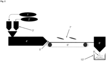
- the thermoplastic K 2 is compounded with the salt and the plasticizer in a twin-screw extruder, whereby granules are obtained, as in Fig. 2 shown.
- the twin screw extruder can be co-rotating or counter-rotating.
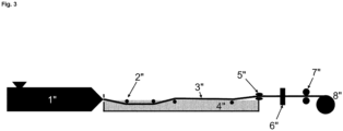
- a planetary roller extruder or co-kneader can also be used. If necessary, the obtained granules can be processed into a filament using a single-screw extruder, as in Fig. 3 shown.
- the present invention is not particularly limited as far as the salt for compounding with the at least one thermoplastic K 2 is concerned.
- salts are expediently used which, in addition to having a high solubility in the aqueous solvent used, in particular in water, do not react with it in an acidic or basic manner, that is, they leave the pH value of the aqueous solvent, in particular water, almost unchanged.
- the salts used should also only have a low hygroscopicity, so that excessive water absorption does not occur during additive manufacturing, which would otherwise adversely affect the stability of the support structure.
- the salts used are neither environmentally hazardous nor otherwise objectionable.
- the salt with which the at least one thermoplastic K 2 is compounded is selected from the group consisting of sodium chloride, sodium sulfate, sodium nitrate, potassium chloride, potassium sulfate and potassium nitrate, but is not limited to this.
- the chlorides, sulfates and nitrates of the light alkali metals sodium and potassium are characterized by their high water solubility. They are also largely ecologically harmless. In principle, however, the corresponding chlorides, sulfates and nitrates of alkaline earth metals such as magnesium and calcium can also be used for compounding, as can those of other metals, provided they meet the criteria mentioned above.
- plasticizer for compounding with the at least one thermoplastic material K 2 is concerned, the present invention is also not subject to any particular restrictions.
- plasticizers which are soluble in the aqueous solvent used in particular in water
- plasticizers which are insoluble in the aqueous solvent used, in particular in water can also be used here.
- the plasticizers used are neither environmentally hazardous nor otherwise objectionable.
- the plasticizer is polyethylene glycol (PEG).
- PEG polyethylene glycol
- the melting point of PEG increases as the chain length increases. From a molecular weight of around 1,500 g/mol, PEG exists as a waxy solid at room temperature.
- PEG polyethylene glycol
- citric acid esters, glycerols and their derivatives such as tributyrin and triacetin fatty acid esters such as methyl oleate and epoxidized esters and oils such as epoxidized soybean oil (ESO) are particularly suitable plasticizers.
- the meltable material M 2 based on 100 parts by mass of the total amount of the at least one thermoplastic material K 2 , there are 100 to 150 parts by mass of the salt and 10 to 50 parts by mass of the plasticizer, preferably 115 to 135 parts by mass of the salt and 20 to 35 parts by mass of the plasticizer, for example 125 parts by mass of the salt and 25 parts by mass of the plasticizer, are present. If the proportion of plasticizer is too low in relation to the proportion of salt, the meltable material M 2 is too brittle. The result is inadequate processability, which manifests itself, for example, in clogging or wear of the nozzle as well as in tearing of the melt strand when the meltable material M 2 is repeatedly deposited to build up the support structure.
- the meltable material M 2 is too brittle, the filament tears off when it is fed into the extruder.
- the proportion of plasticizer is too high in relation to the proportion of salt, the meltable material M 2 is not stiff enough. As a result of this, the support structure deforms under the load of the plastic component, which also results in a deformation of the plastic component.
- the at least one thermoplastic K 2 can be further compounded with one or more additives selected from the group consisting of flow aids, impact modifiers, nucleating agents and fillers.
- one or more additives selected from the group consisting of flow aids, impact modifiers, nucleating agents and fillers.
- the viscosity of the meltable material M 2 can be adjusted using flow aids such as epoxides, peroxides or isocyanates.
- the energy absorption capacity of the meltable material M 2 can be influenced using impact modifiers.
- nucleating agents which are also referred to as nucleating agents, such as boron nitride, which is already contained in commercially available PHBV
- nucleating agents such as boron nitride
- the addition of nucleating agents also prevents post-crystallization, which would otherwise lead to warping of the support structure.
- Fillers such as wood flour, coal, graphite, cellulose powder, shell and kernel flour can ultimately influence the density, the modulus of elasticity, the hardness, the heat resistance and the tendency to shrink of the meltable material M 2 .
- step (b) of the manufacturing method according to the invention the support structure is removed from the plastic component constructed in step (a) after its completion by bringing it into contact with an aqueous solvent.
- the aqueous solvent is not particularly limited and includes all solvents having a water content of at least 50% by volume.
- the aqueous solvent can contain portions of organic solvents, such as alcohols, etc., or additives, such as special salts, etc.
- the aqueous solvent can also contain acids or bases. Because it is easier to handle and for ecological reasons, the use of an aqueous solvent, which is essentially, i.e. H. consists of at least 95% by volume of water, preferably.
- the aqueous solvent is water.
- the salt compounded together with the at least one thermoplastic K 2 dissolves as soon as it comes into contact with the aqueous solvent, in particular with water. What remains is a porous structure of at least one thermoplastic material K2 , which does not dissolve. Since this porous structure is mechanically unstable, it breaks down into fragments with dimensions ranging from a few micrometers to a few centimeters, which means that it can be easily separated from the finished plastic component. There is therefore no need for any complex mechanical post-processing to remove the support structure from the finished plastic component. Rather, in the context of the production method according to the invention, the support structure separates to a certain extent on its own as a result of being brought into contact with the aqueous solvent, in particular with water.
- the support structure breaks down into sufficiently small fragments while the compounded salt is dissolving, so that almost no residue remains on the finished plastic component and no post-processing is necessary.
- a thermoplastic that is not biodegradable is used for the support structure, the above-mentioned fragments of the support structure are expediently filtered out of the aqueous solvent in order not to end up in the environment. Such filtering is only possible because the at least one thermoplastic K 2 itself is not water-soluble.
- thermoplastic material K 2 is a naturally occurring polymer, as is the case with the biopolymers shown above, for example polyhydroxyalkanoates, such as polyhydroxybutyric acid, microorganisms, fungi and enzymes present in the aqueous solvent, in particular in water, can form the fragments of the Dismantle the support structure made of at least one thermoplastic K 2 .
- polyhydroxyalkanoates such as polyhydroxybutyric acid, microorganisms, fungi and enzymes present in the aqueous solvent, in particular in water
- the use of a biodegradable thermoplastic also enables simplified disposal of the Create support structure.
- the fragments made of the at least one thermoplastic material K 2 have comparatively small dimensions, they can easily be disposed of via the drain.
- Wastewater in particular contains a large number of microorganisms, such as bacteria, which allow degradation under aerobic or anaerobic conditions under which their growth is possible.
- Decomposition products are essentially carbon dioxide and water.
- the at least one thermoplastic K 2 is correspondingly biodegradable. In this case, there is no need to filter off the above-mentioned fragments of the support structure from the aqueous solvent, but it may still be desirable for reasons of sustainability, for example in order to enable recycling.
- the at least one thermoplastic material K 2 which itself is not water-soluble, can for this purpose be selected from the group consisting of polyhydroxyalkanoates, in particular poly(3-hydroxybutyrate), poly(3-hydroxybutyrate-co-3- hydroxyvalerate) and poly(3-hydroxybutyrate-co-3-hydroxyhexanoate), as well as polycaprolactone, thermoplastic starch, polybutylene adipate terephthalate and polybutylene succinate, may be selected, but are not limited to this.
- the present invention relates to a filament, granulate or powder of the meltable material M 2 for use as a support structure, for example in the production method according to the invention.
- the filament according to the invention can have a diameter in the range of 1 mm to 4 mm, for example 1.5 mm to 3.5 mm.
- Commercially available diameters include: B. 1.75 mm or 2.85 mm. The dimensions mentioned above also apply to the diameter of the granules according to the invention.
- the present invention allows a simple, residue-free and stress-free separation of the support structure from a plastic component of complex geometry, which is produced by additive manufacturing, for example melt layers. Since no mechanical post-processing is required, there is no impairment of the external appearance of the plastic component produced. In particular, its surface quality is not negatively affected. This is achieved by using a support structure made of a meltable material M 2 , which is formed from at least one thermoplastic material K 2 , which is compounded with at least a salt and a plasticizer.
- the present invention also allows the support structure to be easily disposed of, provided that the at least one thermoplastic material K 2 is biodegradable.
- the aqueous solvent brought into contact with the support structure, in particular water can, for example, simply be poured into the drain.
- Microorganisms, fungi or enzymes contained in the wastewater ultimately break down the at least one thermoplastic K 2 , which has broken down into fragments as a result of contact with the aqueous solvent, in particular with water. Since neither acids nor bases have to be used in the production process according to the invention, microorganisms, such as bacteria, which react sensitively to the pH value of the water, are not disturbed in their descendantss by disposing of the support structure with the wastewater.
- the fragments emerging from the support structure have at least one thermoplastic material K 2 has a high specific surface area, which further accelerates the biological degradation process.
- no residues of the at least one thermoplastic material K 2 originating from the support structure remain in the environment.
- the at least one thermoplastic K 2 can precipitate again and then remains in the environment as microplastics, for example in the form of individual polymer chains. This ultimately enters the food chain via soil or water.
- the production method according to the invention and the filament, granules or powder according to the invention do not have all of these problems, especially if the at least one thermoplastic material K 2 used for the support structure is biodegradable.
- the support structures were then constructed by strand deposition at a deposition speed of 36 mm/s, a nozzle temperature of 190 °C, a platform temperature of 75 °C and a relative flow rate of approximately 105%. Photographs of the support structures constructed in this way are in Fig. 4(a) shown, left for material A and right for material B. Three consecutive shots of the construction process of the support structure are shown from top to bottom. It can be seen that the support structure made of material A had a more inhomogeneous surface structure compared to that made of material B. This can be explained by the lower viscosity in the case of material A, due to the higher proportion of plasticizer in the composition. Like the photographs Fig. 4(b) can be seen, the surface structure was ultimately transferred to the plastic component to be manufactured. Despite the more inhomogeneous surface structure, satisfactory results could still be achieved with the support structure made of material A.
- the impact strength was determined depending on the composition of the meltable material.
- material C material D
- material E material F
- Table 2 The composition of the corresponding compounds (in parts by mass of the respective components) is shown in Table 2 below: Table 2 Bulk parts PHBV Bulk parts PEG Mass parts NaCl Material C 100 40 60 Material D 100 00 42.86 Material E 100 50 100 Material F 100 00 66.67
- meltable materials M 2 were used, hereinafter referred to as material G, material H, material I, material J and material K.
- the composition of the corresponding compounds is shown in Table 3 below: Table 3 Bulk parts PHBV Bulk parts PEG Mass parts NaCl Material G 100 50 100 Material H 100 40 60 Material I 100 25 125 Material J 100 11.11 111.11 Material K 100 24 76
- the soluble portion results from the total amount of plasticizer and salt. It turns out that in all cases a significant portion of the support structure was dissolved in water after four hours.
- the presence of the plasticizer in the meltable material M 2 can reduce the brittleness of the support structure, which results from the addition of the salt, without adversely affecting the functionality of the support structure.
Landscapes
- Chemical & Material Sciences (AREA)
- Engineering & Computer Science (AREA)
- Materials Engineering (AREA)
- Manufacturing & Machinery (AREA)
- Physics & Mathematics (AREA)
- Mechanical Engineering (AREA)
- Optics & Photonics (AREA)
Abstract
Description
- Die vorliegende Erfindung betrifft ein Verfahren zur Herstellung eines Kunststoffbauteiles durch additive Fertigung, wobei das herzustellende Kunststoffbauteil eine komplexe Geometrie aufweisen soll, welche den Einsatz einer Stützstruktur erfordert. Ferner betrifft die vorliegende Erfindung ein Filament, Granulat oder Pulver zur Verwendung als Stützstruktur in dem erfindungsgemäßen Herstellungsverfahren.
- Im Stand der Technik sind verschiedene additive Fertigungsverfahren bekannt, um Kunststoffbauteile unter Anwendung eines 3D-Drucks in Kleinserien oder als Prototyp herzustellen, wie etwa das selektive Lasersintern (engl. selective laser sintering, SLS) oder das Schmelzschichten (engl. fused deposition modeling, FDM). Das auch als Strangablegeverfahren bezeichnete Schmelzschichten ist ein Fertigungsverfahren aus dem Bereich Rapid Prototyping, mit dem ein Bauteil schichtweise aus einem schmelzfähigen Ausgangsstoff, beispielsweise einem schmelzfähigen Kunststoff, aufgebaut wird.
- Um in einem derartigen mittels additiver Fertigung herzustellenden Kunststoffbauteil komplexe Geometrien, wie etwa Überhänge bzw. Hinterschneidungen, zu ermöglichen, bedarf es des Einsatzes einer Stützstruktur. Stützstrukturen, welche synonym auch als Stützkonstruktionen bezeichnet werden, kommen überall dort zum Einsatz, wo das herzustellende Kunststoffbauteil freistehend bzw. freihängend sein soll, d. h. an all jenen Stellen, die ansonsten frei im Raum, also ohne Stützung durch eine bereits fertiggestellte Teilkomponente des Kunststoffbauteiles, entstehen würden. Die Stützstruktur vermittelt somit den notwendigen Halt der während der additiven Fertigung aufgetragenen Kunststoffschmelze, welche nach Erstarrung das Kunststoffbauteil bildet. Das Prinzip des Strangablegeverfahrens, eines der am häufigsten angewandten 3D-DruckVerfahren, ist in
Fig. 1 veranschaulicht. - Nach der Fertigstellung bzw. dem Erstarren des Kunststoffbauteiles ist dieses in den Bereichen, wo sich die Überhänge bzw. Hinterschneidungen befinden, selbsttragend. Die Stützstruktur ist nunmehr überflüssig bzw. vielmehr störend. Sie muss daher entfernt, also von dem hergestellten Kunststoffbauteil abgetrennt werden. Häufig bestehen die in der additiven Fertigung eingesetzten Stützstrukturen aus dem gleichen Werkstoff wie das herzustellende Kunststoffbauteil. In diesem Fall muss die Stützstruktur nach der Fertigstellung des Kunststoffbauteiles mechanisch von diesem entfernt werden, vorwiegend in zeitintensiver Handarbeit. Selbst eine aufwendige mechanische Nachbearbeitung mittels Schleifen und Polieren kann hierbei nicht immer verhindern, dass Rückstände der Stützstruktur am Kunststoffbauteil haften bleiben, was dessen äußeres Erscheinungsbild negativ beeinflusst. Ebenso können durch die mechanische Nachbearbeitung Kratzer in der Oberfläche des Kunststoffbauteiles entstehen, welche sich ebenfalls negativ auf dessen äußeres Erscheinungsbild auswirken. Werden die Stützstrukturen unter erhöhtem Krafteinsatz entfernt, kann es sogar zu einer Vorschädigung des Kunststoffbauteiles kommen.
- Zwar wurde in diesem Zusammenhang durch die Kombination unterschiedlicher Werkstoffe für das Kunststoffbauteil und für die Stützstruktur, welche weniger stark aneinander haften, eine Verbesserung erzielt. Da es jedoch beim Stützen des Kunststoffbauteiles notwendigerweise zu einer Kraftübertragung auf die Stützstruktur kommt, kann zwar die Haftung verringert, jedoch nie vollständig unterbunden werden. Somit lassen sich auch bei Verwendung unterschiedlicher Werkstoffe die vorstehend beschriebenen Probleme, wie sie bislang beim Entfernen der Stützstruktur auftreten, nicht vollständig vermeiden.
- Im Stand der Technik sind auch Stützstrukturen aus wasserlöslichen Polymeren, wie etwa Polyvinylpyrrolidon, bekannt, die nach der Fertigstellung des Kunststoffbauteiles ausgewaschen werden können. Die in Wasser gelösten Polymerketten der Stützstruktur können jedoch nicht über eine übliche Kläranlage aus dem Abwasser entfernt werden, womit sie letztlich in die Umwelt gelangen. Die Folgen dieser Art der Umweltverschmutzung auf Mensch und Natur sind noch nicht erforscht.
- Der vorliegenden Erfindung liegt somit die Aufgabe zugrunde, ein Verfahren bereitzustellen, welches die Herstellung eines Kunststoffbauteiles komplexer Geometrie durch additive Fertigung erlaubt, wobei sich die hierbei zum Einsatz kommende Stützstruktur nach Beendigung der additiven Fertigung rückstands- und belastungsfrei von dem fertiggestellten Kunststoffbauteil abtrennen lassen soll, ohne dabei dessen äußeres Erscheinungsbild zu beeinträchtigen und ohne dabei idealerweise die Umwelt zu schädigen.
- Diese Aufgabe wird durch die in den Ansprüchen gekennzeichneten Ausführungsformen der vorliegenden Erfindung gelöst.
- Insbesondere wird erfindungsgemäß ein Verfahren zur Herstellung eines Kunststoffbauteiles durch additive Fertigung bereitgestellt, welches die folgenden Schritte (a) und (b) umfasst:
- (a) wiederholtes Ablegen eines schmelzfähigen Materials M1, welches aus mindestens einem thermoplastischen Kunststoff K1 gebildet ist, zum Aufbau eines Kunststoffbauteiles mit vorgegebener Geometrie, wobei während des Aufbaus des Kunststoffbauteiles eine Stützstruktur aus einem schmelzfähigen Material M2 zur Ermöglichung von Überhängen bzw. Hinterschneidungen im Kunststoffbauteil verwendet wird, und
- (b) Entfernen der Stützstruktur von dem in Schritt (a) aufgebauten Kunststoffbauteil nach dessen Fertigstellung durch Inkontaktbringen mit einem wässrigen Lösungsmittel,
- Das erfindungsgemäße Herstellungsverfahren ermöglicht ein rückstands- und belastungsfreies Entfernen der Stützstruktur nach Fertigstellung des Kunststoffbauteiles, ohne dass es einer aufwendigen mechanischen Nachbearbeitung, etwa durch Schleifen oder Polieren, bedarf. Die Gefahr einer Beschädigung des Kunststoffbauteiles beim Abtrennen der Stützstruktur wird auf diese Weise nahezu gänzlich minimiert. Erreicht wird dies durch den Einsatz einer Stützstruktur aus einem schmelzfähigen Material M2, das aus mindestens einem thermoplastischen Kunststoff K2, welcher zumindest mit einem Salz und einem Weichmacher compoundiert ist, gebildet ist. Wird nach Beendigung der additiven Fertigung das fertiggestellte Kunststoffbauteil einschließlich der noch anhaftenden Stützstruktur mit einem wässrigen Lösungsmittel, insbesondere mit Wasser, in Kontakt gebracht, löst sich das in dem schmelzfähigen Material M2 enthaltene und zusammen mit dem mindestens einen thermoplastischen Kunststoff K2 compoundierte Salz auf. Der mindestens eine thermoplastische Kunststoff K2 geht hingegen nicht in Lösung und bleibt stattdessen als poröses Gebilde zurück. Dieses zerfällt schließlich in Bruchstücke mit Abmessungen im Bereich von wenigen Mikrometern bis hin zu einigen Zentimetern. Der mindestens eine thermoplastische Kunststoff K2 trennt sich nach dem Auflösen des Salzes somit gewissermaßen von allein ab. Durch die Anwesenheit eines Weichmachers, der ebenfalls in dem schmelzfähigen Material M2 enthalten und zusammen mit dem mindestens einen thermoplastischen Kunststoff K2 compoundiert ist, wird zudem sichergestellt, dass die vom Zusatz des Salzes herrührende Sprödigkeit verringert wird. Das schmelzfähige Material M2, welches dem Aufbau der Stützstruktur dient, behält somit eine ausreichende Verarbeitbarkeit.
- Gemäß der vorliegenden Erfindung meint der Begriff "schmelzfähig" im Zusammenhang mit dem schmelzfähigen Material M1 bzw. M2, dass zumindest der mindestens eine thermoplastische Kunststoff K1 bzw. K2 in einen extrudierbaren Zustand überführt werden kann. Man spricht in diesem Zusammenhang auch von einem Plastifizieren des schmelzfähigen Materials M1 bzw. M2. Andere Bestandteile des schmelzfähigen Materials M1 bzw. M2 können hingegen in der Kunststoffschmelze als Feststoff dispergiert verbleiben.
- Auch wenn der mindestens eine thermoplastische Kunststoff K2 selbst nicht wasserlöslich ist, kann aufgrund der Wasserlöslichkeit des in dem schmelzfähigen Material M2 enthaltenen Salzes von einer wasserlöslichen Stützstruktur gesprochen werden. Ist der mindestens eine thermoplastische Kunststoff K2 zudem biologisch abbaubar, kann die Stützstruktur nach dem Inkontaktbringen mit dem wässrigen Lösungsmittel, insbesondere mit Wasser, bedenkenlos mit dem Abwasser entsorgt werden, ohne hierbei einen schädlichen Eintrag von Kunststoffen in die Umwelt zu verursachen.
- Im Folgenden wird das erfindungsgemäße Verfahren zur Herstellung eines Kunststoffbauteiles durch additive Fertigung mit den Schritten (a) und (b) unter Verweis auf
Fig. 1 näher beschrieben, wobei die darin gezeigte Darstellung des erfindungsgemäßen Herstellungsverfahrens nicht als einschränkend aufzufassen ist. - In Schritt (a) des erfindungsgemäßen Herstellungsverfahrens wird ein schmelzfähiges Material M1, welches aus mindestens einem thermoplastischen Kunststoff K1 gebildet ist, wiederholt zum Aufbau eines Kunststoffbauteiles mit vorgegebener Geometrie abgelegt.
- Das wiederholte Ablegen des schmelzfähigen Materials M1 kann, wie in
Fig. 1 dargestellt, mit Hilfe eines (Mini-)Extruders (7) erfolgen. Ein Kunststoffdraht (1) des schmelzfähigen Materials M1, welcher auch als Kunststofffilament oder nur als Filament bezeichnet wird, tritt - nach Erwärmen über den Schmelzpunkt des mindestens einen thermoplastischen Kunststoffes K1 hinaus - in Form einer Kunststoffschmelze aus der Düse (5) einer zum Schmelzschichten geeigneten 3D-Druckvorrichtung aus. Durch linienartige Auftragung (8) der Kunststoffschmelze wird nach und nach das Kunststoffbauteil (6) entsprechend der vorgegebenen Geometrie schichtweise aufgebaut, wobei im Rahmen des Schmelzschichtens auf einer bereits fertiggestellten, d. h. erstarrten Teilkomponente des Kunststoffbauteiles weitere Schichten des schmelzfähigen Materials M1 entstehen. - Das linienartige Auftragen der Kunststoffschmelze, wobei man sinngemäß auch von einem wiederholten Ablegen eines Schmelzstranges spricht, kann auf einer beliebigen für das Schmelzschichten geeigneten Bauplattform (10) erfolgen. Beispielsweise auf einer solchen Bauplattform, wie sie in
Fig. 1 dargestellt ist, befindet sich die Stützstruktur (9), welche komplexe Geometrien, wie etwa Überhänge bzw. Hinterschneidungen, im herzustellenden Kunststoffbauteil ermöglicht. In gleicher Weise kann sich die Stützstruktur jedoch auch auf einer bereits fertiggestellten Teilkomponente des Kunststoffbauteiles befinden. - Das erfindungsgemäße Herstellungsverfahren ist nicht auf ein Schmelzschichten beschränkt. So kann vorliegend grundsätzlich jede andere Form der additiven Fertigung zur Herstellung eines Kunststoffbauteiles Anwendung finden, solange diese den Einsatz einer Stützstruktur vorsieht.
- In einer Ausführungsform des vorstehend definierten Herstellungsverfahrens wird in Schritt (a) während des Aufbaus des Kunststoffbauteiles die Stützstruktur durch wiederholtes Ablegen des schmelzfähigen Materials M2 aufgebaut. Dies ist insbesondere dann zweckmäßig, wenn mehrere Stützstrukturen an unterschiedlichen Positionen zum Einsatz kommen sollen, was auch erst im weiteren Verlauf der additiven Fertigung der Fall sein kann. Der Aufbau des Kunststoffbauteiles und der Aufbau der Stützstruktur können hierbei parallel erfolgen. Zweckmäßigerweise kann zum Aufbau des Kunststoffbauteiles und zum Aufbau der Stützstruktur eine 3D-Druckvorrichtung mit mindestens zwei Extrudern und Düsen verwendet werden, wie sie in
Fig. 1 exemplarisch dargestellt ist, wobei die 3D-Druckvorrichtung sowohl mit einem Filament (1) des schmelzfähigen Materials M1 als auch mit einem Filament (2) des schmelzfähigen Materials M2 ausgestattet ist, wie weiter unten näher beschrieben. Vortrieb (3) sowie Kontaktheizung (4) der 3D-Druckvorrichtung sind inFig. 1 ebenfalls dargestellt. Anstelle von Filamenten des schmelzfähigen Materials M1 und des schmelzfähigen Materials M2 können auch entsprechende Granulate oder Pulver hiervon verwendet werden. - Die vorliegende Erfindung umfasst auch Ausführungsformen, in denen mehr als zwei verschiedene schmelzfähige Materialien zum Einsatz kommen. Beispielsweise können - abgesehen vom schmelzfähigen Material M2 - zwei verschiedene schmelzfähige Materialien M1a und M1b verwendet werden, welche vorzugsweise aus zwei verschiedenen Extrudern bereitgestellt werden und das Kunststoffbauteil bilden. Diese zwei verschiedenen schmelzfähigen Materialien M1a und M1b können sich je nach Zweck sowohl in der Art des mindestens einen thermoplastischen Kunststoffes K1 als auch in der Farbe oder in anderen Eigenschaften unterscheiden. Das schmelzfähige Material M2, aus welchem die Stützstruktur gebildet ist/wird, kann hier beispielsweise aus einem dritten Extruder bereitgestellt werden. Weitere Kombinationen von schmelzfähigen Materialien (etwa M1a/M1b/M1c/M2 oder M1/M2a/M2b) sind ebenfalls im Sinne der vorliegenden Erfindung denkbar.
- Da gemäß der vorliegenden Erfindung die Wasserlöslichkeit der Stützstruktur auf der Löslichkeit des mit dem mindestens einen thermoplastischen Kunststoff K2 compoundierten Salzes beruht, können der mindestens eine thermoplastische Kunststoff K1 des schmelzfähigen Materials M1, welches dem Aufbau des Kunststoffbauteiles dient, und der mindestens eine thermoplastische Kunststoff K2 des schmelzfähigen Materials M2, welches dem Aufbau der Stützstruktur dient, sogar identisch sein. So bleibt nach Kontakt mit einem wässrigen Lösungsmittel, insbesondere mit Wasser, die Stützstruktur als ein poröses Gebilde aus dem mindestens einen thermoplastischen Kunststoff K1 = K2 zurück, welches schließlich in Bruchstücke mit Abmessungen im Bereich von wenigen Mikrometern bis hin zu einigen Zentimetern zerfällt. Das aus dem identischen thermoplastischen Kunststoff aufgebaute Kunststoffbauteil wird aufgrund der fehlenden Wasserlöslichkeit des mindestens einen thermoplastischen Kunststoffes K1 = K2 hingegen nicht angegriffen.
- Durch die Verwendung identischer thermoplastischer Kunststoffe ist eine Kompatibilität zwischen dem Kunststoffbauteil und der Stützstruktur naturgemäß gewährleistet. Bei Stützstrukturen aus wasserlöslichen Polymeren, wie etwa Polyvinylpyrrolidon, bei dem es sich um einen konventionellen, erdölbasierten Kunststoff handelt, welcher zudem nicht biologisch abbaubar ist, muss für das herzustellende Kunststoffbauteil hingegen zwangsläufig ein anderer thermoplastischer Kunststoff verwendet werden.
- Gemäß der vorliegenden Erfindung ist der mindestens eine thermoplastische Kunststoff K1 des schmelzfähigen Materials M1, welches dem Aufbau des Kunststoffbauteiles dient, nicht weiter eingeschränkt. So kann grundsätzlich jeder thermoplastische Kunststoff, wie er üblicherweise in der additiven Fertigung von Kunststoffbauteilen eingesetzt wird, auch im erfindungsgemäßen Herstellungsverfahren verwendet werden.
- In einer Ausführungsform des vorstehend definierten Herstellungsverfahrens ist der mindestens eine thermoplastische Kunststoff K1 aus der Gruppe, bestehend aus Polyestern, Polyamiden, Polyurethanen, Polycarbonaten, Polyketonen und Polyolefinen, ausgewählt und gegebenenfalls ein thermoplastisches Elastomer. Falls gewünscht, kann der mindestens eine thermoplastische Kunststoff K1 also elastomere Eigenschaften aufweisen. Bei dem mindestens einen thermoplastischen Kunststoff K1 kann es sich sowohl um Homopolymere als auch um Copolymere sowie um entsprechende Gemische hiervon handeln. In einer weiteren Ausführungsform des vorstehend definierten Herstellungsverfahrens ist der mindestens eine thermoplastische Kunststoff K1 insbesondere aus der Gruppe, bestehend aus Polylactid (PLA), Acrylnitril-Butadien-Styrol-Copolymer (ABS), Acrylnitril-Styrol-Acrylat-Copolymer (ASA), Polymethylmethacrylat (PMMA), Polyetheretherketon (PEEK) und Glykol-modifiziertem Polyethylenterephthalat (PETG), ausgewählt, ohne jedoch hierauf beschränkt zu sein. Gemäß einer bevorzugten Ausführungsform der vorliegenden Erfindung ist der mindestens eine thermoplastische Kunststoff K1 PLA oder ABS.
- Typischerweise sollte der mindestens eine thermoplastische Kunststoff K1 eine Schmelztemperatur von etwa 250 °C nicht überschreiten, damit seine Verarbeitbarkeit und Handhabung in der additiven Fertigung, beispielsweise im Schmelzschichten, gewährleistet bleiben.
- Falls erforderlich, kann der mindestens eine thermoplastische Kunststoff K1 mit einem oder mehreren Additiven compoundiert sein. Hierdurch lassen sich dem schmelzfähigen Material M1, welches dem Aufbau des Kunststoffbauteiles dient, bestimmte Eigenschaften verleihen. Neben Weichmachern sind als mögliche Additive Fließhilfsmittel, Schlagzähmodifizierer, Keimbildner und Füllstoffe zu nennen, wie sie weiter unten im Zusammenhang mit dem schmelzfähigen Material M2 näher beschrieben sind. Das Compoundieren ist ebenfalls weiter unten näher beschrieben.
- Gemäß der vorliegenden Erfindung ist der zumindest mit einem Salz und einem Weichmacher compoundierte mindestens eine thermoplastische Kunststoff K2 des schmelzfähigen Materials M2, welches dem Aufbau der Stützstruktur dient, nicht weiter eingeschränkt, solange er nicht wasserlöslich ist. Mit der Maßgabe, dass der mindestens eine thermoplastische Kunststoff K2 nicht wasserlöslich ist, kann grundsätzlich jeder thermoplastische Kunststoff, wie er üblicherweise in der additiven Fertigung, beispielsweise im Schmelzschichten, für Stützstrukturen eingesetzt wird, auch im erfindungsgemäßen Herstellungsverfahren verwendet werden, einschließlich der im Zusammenhang mit dem schmelzfähigen Material M1 vorstehend genannten thermoplastischen Kunststoffe. Wie im Falle des mindestens einen thermoplastischen Kunststoffes K1 kann es sich bei dem mindestens einen thermoplastischen Kunststoff K2 sowohl um Homopolymere als auch um Copolymere sowie um entsprechende Gemische hiervon handeln. Ist der mindestens eine thermoplastische Kunststoff K2 biologisch abbaubar, wie weiter unten beschrieben, ist eine Entsorgung der Stützstruktur nach der Fertigstellung des Kunststoffbauteiles über das Abwasser bedenkenlos möglich.
- In einer Ausführungsform des vorstehend definierten Herstellungsverfahrens ist der mindestens eine thermoplastische Kunststoff K2 aus der Gruppe, bestehend aus Polyhydroxyalkanoaten (PHA), insbesondere Poly-3-hydroxybutyrat (PHB), Poly(3-hydroxybutyrat-co-3-hydroxyvalerat) (PHBV) und Poly(3-hydroxybutyrat-co-3-hydroxyhexanoat), sowie Polycaprolacton (PCL), thermoplastischer Stärke, Polybutylenadipatterephthalat (PBAT) und Polybutylensuccinat (PBS), ausgewählt, ohne jedoch hierauf beschränkt zu sein. All diesen (Bio-)Polymeren ist gemeinsam, dass sie biologisch abbaubar sind. Während thermoplastische Stärke und PCL in Gewässern biologisch abbaubar sind, sind PBAT und PBS weniger in Gewässern, dafür aber in Böden biologisch abbaubar.
- Polyhydroxyalkanoate, welche auch als Polyhydroxyfettsäuren bezeichnet werden, lassen sich sowohl in Gewässern als auch in Böden biologisch abbauen. Bei ihnen handelt es sich um natürlich vorkommende, wasserunlösliche Polyester, welche von Mikroorganismen, beispielsweise Bakterien, aerob oder anaerob abgebaut werden können. Bei dem mindestens einen thermoplastischen Kunststoff K2 kann es sich demnach um ein Polyhydroxyalkanoat, wie etwa Poly(3-hydroxybuttersäure), handeln. Poly(3-hydroxybuttersäure), welche auch als Poly(3-hydroxybutyrat) bezeichnet wird, ist ein strukturell einfaches und in der Natur häufig vorkommendes Polyhydroxyalkanoat. PHB wird durch Fermentation gebildet, beispielsweise auf Basis von Zucker oder Stärke, und besteht üblicherweise aus 1.000 bis mehreren 100.000 3-Hydroxybuttersäureeinheiten. Zumeist leitet sich die natürlich vorkommende Poly(3-hydroxybuttersäure) von dem Monomer mit (R)-Konfiguration ab. Es handelt sich demnach um Poly-(R)-(3-hydroxybutyrat). Das Monomer mit (S)-Konfiguration und das entsprechende Poly-(S)-(3-hydroxybutyrat) spielen demgegenüber lediglich eine untergeordnete Rolle, ebenso wie die racemische Mischung aus Poly-(R)-(3-hydroxybutyrat) und Poly-(S)-(3-hydroxybutyrat). Natürlich vorkommende Poly(3-hydroxybuttersäure) weist einen Schmelzpunkt von etwa 175 °C auf, oberhalb von 200 °C tritt Zersetzung ein. In einem Teil ihrer Eigenschaften ist Poly(3-hydroxybuttersäure) mit Polypropylen vergleichbar, insbesondere hinsichtlich Kristallinität, Glasübergangstemperatur und Zugfestigkeit. Vorliegend wird, wenn auf Poly(3-hydroxybuttersäure) Bezug genommen wird, jedwedes Stereoisomer hiervon, d. h. gleich welcher Taktizität, verstanden. Neben PHB sind insbesondere auch das Copolymer von 3-Hydroxybuttersäure und 3-Hydroxyvaleriansäure, also Poly(3-hydroxybutyrat-co-3-hydroxyvalerat), und das Copolymer von 3-Hydroxybuttersäure und 3-Hydroxyhexansäure, also Poly(3-hydroxybutyrat-co-3-hydroxyhexanoat), als besonders geeignete thermoplastische Kunststoffe für das schmelzfähige Material M2 zu nennen. 3-Hydroxyvaleriansäure und 3-Hydroxyhexansäure folgen in der homologen Reihe auf 3-Hydroxybuttersäure. Sie weisen also im Vergleich hierzu eine bzw. zwei zusätzliche Methylengruppen auf, wodurch bei nahezu gleichbleibender biologischer Abbaubarkeit die Dehnfähigkeit zunimmt und die Sprödigkeit abnimmt.
- Gemäß der vorliegenden Erfindung ist der mindestens eine thermoplastische Kunststoff K2 zumindest mit einem Salz und einem Weichmacher compoundiert, d. h. gemischt. Das Salz und der Weichmacher werden als Zuschlagstoffe dem mindestens einen thermoplastischen Kunststoff K2 beigemischt. Dies gilt in gleicher Weise für die nachstehend genannten Additive, sofern vorgesehen. Zu diesem Zweck können alle Verfahren eingesetzt werden, wie sie beim Compoundieren in der Kunststofftechnik üblich sind. Typischerweise erfolgt die Compoundierung des thermoplastischen Kunststoffes K2 mit dem Salz und dem Weichmacher in einem Doppelschneckenextruder, wodurch ein Granulat erhalten wird, wie in
Fig. 2 dargestellt. Der Doppelschneckenextruder kann dabei gleichläufig oder gegenläufig sein. Anstelle eines Doppelschneckenextruders kann jedoch auch ein Planetwalzenextruder oder ein Ko-Kneter verwendet werden. Bei Bedarf kann das erhaltene Granulat unter Verwendung eines Einschneckenextruders zu einem Filament verarbeitet werden, wie inFig. 3 dargestellt. - Grundsätzlich ist die vorliegende Erfindung, was das Salz zur Compoundierung mit dem mindestens einen thermoplastischen Kunststoff K2 anbelangt, nicht besonders eingeschränkt. Zweckmäßigerweise werden hierzu Salze verwendet, welche neben einer hohen Löslichkeit in dem verwendeten wässrigen Lösungsmittel, insbesondere in Wasser, mit diesem weder sauer noch basisch reagieren, d. h. den pH-Wert des wässrigen Lösungsmittels, insbesondere von Wasser, nahezu unverändert lassen. Auch sollten die eingesetzten Salze lediglich eine geringe Hygroskopizität aufweisen, damit es nicht bereits während der additiven Fertigung zu einer übermäßigen Aufnahme von Wasser kommt, was ansonsten die Stabilität der Stützstruktur nachteilig beeinflussen würde. Idealerweise sind die zum Einsatz kommenden Salze weder umweltgefährlich noch anderweitig bedenklich.
- In einer Ausführungsform des vorstehend definierten Herstellungsverfahrens ist das Salz, mit welchem der mindestens eine thermoplastische Kunststoff K2 compoundiert ist, aus der Gruppe, bestehend aus Natriumchlorid, Natriumsulfat, Natriumnitrat, Kaliumchlorid, Kaliumsulfat und Kaliumnitrat, ausgewählt, ohne jedoch hierauf beschränkt zu sein. Die Chloride, Sulfate und Nitrate der leichten Alkalimetalle Natrium und Kalium zeichnen sich durch ihre hohe Wasserlöslichkeit aus. Auch sind sie ökologisch weitestgehend unbedenklich. Grundsätzlich können jedoch auch die entsprechenden Chloride, Sulfate und Nitrate von Erdalkalimetallen wie Magnesium und Calcium zur Compoundierung verwendet werden, wie auch diejenigen anderer Metalle, sofern sie die vorstehend genannten Kriterien erfüllen.
- Was den Weichmacher zur Compoundierung mit dem mindestens einen thermoplastischen Kunststoff K2 anbelangt, unterliegt die vorliegende Erfindung ebenso wenig einer besonderen Einschränkung. Neben Weichmachern, welche in dem verwendeten wässrigen Lösungsmittel, insbesondere in Wasser, löslich sind, können vorliegend auch Weichmacher eingesetzt werden, welche in dem verwendeten wässrigen Lösungsmittel, insbesondere in Wasser, unlöslich sind. Idealerweise sind die zum Einsatz kommenden Weichmacher weder umweltgefährlich noch anderweitig bedenklich.
- In einer Ausführungsform des vorstehend definierten Herstellungsverfahrens ist der Weichmacher Polyethylenglykol (PEG). Naturgemäß nimmt mit zunehmender Kettenlänge der Schmelzpunkt von PEG zu. Ab einer Molmasse von etwa 1.500 g/mol liegt PEG bei Raumtemperatur als wachsartiger Feststoff vor. Neben Polyethylenglykol, welches in Gewässern biologisch abbaubar ist, sind insbesondere auch Zitronensäureester, Glycerine und ihre Derivate wie etwa Tributyrin und Triacetin, Fettsäureester wie etwa Methyloleat sowie epoxidierte Ester und Öle wie etwa epoxidiertes Sojabohnenöl (ESO) als besonders geeignete Weichmacher zu nennen.
- Gemäß der vorliegenden Erfindung sind in dem schmelzfähigen Material M2, bezogen auf 100 Massenteile der Gesamtmenge des mindestens einen thermoplastischen Kunststoffes K2, 100 bis 150 Massenteile des Salzes und 10 bis 50 Massenteile des Weichmachers, vorzugsweise 115 bis 135 Massenteile des Salzes und 20 bis 35 Massenteile des Weichmachers, beispielsweise 125 Massenteile des Salzes und 25 Massenteile des Weichmachers, vorhanden. Ist der Anteil des Weichmachers in Bezug auf den Anteil des Salzes zu niedrig, ist das schmelzfähige Material M2 zu spröde. Die Folge ist eine unzureichende Verarbeitbarkeit, welche sich beispielsweise in einem Verstopfen oder in einer Abnutzung der Düse sowie in einem Abreißen des Schmelzstranges beim wiederholten Ablegen des schmelzfähigen Materials M2 zum Aufbau der Stützstruktur manifestiert. So reißt etwa beim Strangablegeverfahren, wenn das schmelzfähige Material M2 zu spröde ist, das Filament bei der Zuführung in den Extruder ab. Ist der Anteil des Weichmachers in Bezug auf den Anteil des Salzes hingegen zu hoch, ist das schmelzfähige Material M2 nicht steif genug. Als Folge hiervon verformt sich die Stützstruktur unter der Last des Kunststoffbauteiles, wodurch es im Ergebnis auch zu einer Verformung des Kunststoffbauteiles kommt.
- Bei Bedarf kann der mindestens eine thermoplastische Kunststoff K2 weiter mit einem oder mehreren Additiven, ausgewählt aus der Gruppe, bestehend aus Fließhilfsmitteln, Schlagzähmodifizierern, Keimbildnern und Füllstoffen, compoundiert sein. Hierdurch lassen sich dem schmelzfähigen Material M2, welches dem Aufbau der Stützstruktur dient, bestimmte Eigenschaften verleihen. Mit Fließhilfsmitteln wie etwa Epoxiden, Peroxiden oder Isocyanaten kann die Viskosität des schmelzfähigen Materials M2 eingestellt werden. Mit Schlagzähmodifizierern lässt sich die Energieaufnahmefähigkeit des schmelzfähigen Materials M2 beeinflussen. Durch den Zusatz von Keimbildnern, welche auch als Nukleierungsmittel bezeichnet werden, wie etwa Bornitrid, das in kommerziell erhältlichem PHBV bereits enthalten ist, lassen sich die Bruchdehnung sowie die Zähigkeit des schmelzfähigen Materials M2 erhöhen. Auch wird durch den Zusatz von Keimbildnern eine Nachkristallisation verhindert, welche anderenfalls zu einem Verziehen (engl. warping) der Stützstruktur führt. Mit Füllstoffen wie etwa Holzmehl, Kohle, Graphit, Cellulosepulver, Schalen- und Kernmehl kann schließlich Einfluss auf die Dichte, den E-Modul, die Härte, die Wärmeformbeständigkeit und die Schwindungsneigung des schmelzfähigen Materials M2 genommen werden.
- In Schritt (b) des erfindungsgemäßen Herstellungsverfahrens wird die Stützstruktur von dem in Schritt (a) aufgebauten Kunststoffbauteil nach dessen Fertigstellung durch Inkontaktbringen mit einem wässrigen Lösungsmittel entfernt.
- Gemäß der vorliegenden Erfindung ist das wässrige Lösungsmittel nicht besonders eingeschränkt und schließt sämtliche Lösungsmittel ein, die einen Wasseranteil von mindestens 50 Vol.-% aufweisen. Je nach Anwendung kann das wässrige Lösungsmittel Anteile von organischen Lösungsmitteln, wie Alkoholen usw. oder Additive, wie spezielle Salze usw. aufweisen. Auch kann das wässrige Lösungsmittel Säuren oder Basen enthalten. Aufgrund der einfacheren Handhabbarkeit und aus ökologischen Gründen ist die Verwendung eines wässrigen Lösungsmittels, welches im Wesentlichen, d. h. aus mindestens 95 Vol.-% Wasser besteht, bevorzugt. Gemäß einer spezifischen Ausführungsform der vorliegenden Erfindung ist das wässrige Lösungsmittel Wasser.
- Das zusammen mit dem mindestens einen thermoplastischen Kunststoff K2 compoundierte Salz löst sich, sobald es mit dem wässrigen Lösungsmittel, insbesondere mit Wasser, in Kontakt kommt, auf. Zurück bleibt ein poröses Gebilde des mindestens einen thermoplastischen Kunststoffes K2, welcher nicht in Lösung geht. Da dieses poröse Gebilde mechanisch instabil ist, zerfällt es in Bruchstücke mit Abmessungen im Bereich von wenigen Mikrometern bis hin zu einigen Zentimetern, wodurch es sich von dem fertiggestellten Kunststoffbauteil leicht abtrennen lässt. Es bedarf somit keiner aufwendigen mechanischen Nachbearbeitung, um die Stützstruktur von dem fertiggestellten Kunststoffbauteil zu entfernen. Vielmehr trennt sich im Rahmen des erfindungsgemäßen Herstellungsverfahrens die Stützstruktur in Folge des Inkontaktbringens mit dem wässrigen Lösungsmittel, insbesondere mit Wasser, gewissermaßen von allein ab. Idealerweise zerfällt die Stützstruktur bereits während des Auflösens des compoundierten Salzes in ausreichend kleine Bruchstücke, so dass nahezu keinerlei Rückstände am fertiggestellten Kunststoffbauteil verbleiben und keine Nachbearbeitung notwendig ist. Wird für die Stützstruktur ein thermoplastischer Kunststoff verwendet, welcher nicht biologisch abbaubar ist, werden die vorstehend erwähnten Bruchstücke der Stützstruktur zweckmäßigerweise aus dem wässrigen Lösungsmittel abfiltriert, um nicht in die Umwelt zu gelangen. Ein derartiges Abfiltrieren ist nur möglich, da der mindestens eine thermoplastische Kunststoff K2 selbst nicht wasserlöslich ist. Ist der mindestens eine thermoplastische Kunststoff K2 ein natürlich vorkommendes Polymer, wie dies bei den vorstehend aufgezeigten Biopolymeren, beispielsweise Polyhydroxyalkanoaten, wie etwa Polyhydroxybuttersäure, der Fall ist, können im wässrigen Lösungsmittel, insbesondere in Wasser, vorhandene Mikroorganismen, Pilze und Enzyme die Bruchstücke der Stützstruktur aus dem mindestens einen thermoplastischen Kunststoff K2 abbauen. Neben der vereinfachten Abtrennbarkeit der Stützstruktur, welche auf die Compoundierung mit dem Salz sowie dessen Herauslösen aus der Stützstruktur bei Inkontaktbringen mit dem wässrigen Lösungsmittel, insbesondere mit Wasser, zurückgeführt werden kann, lässt sich bei Verwendung eines biologisch abbaubaren thermoplastischen Kunststoffes ferner also eine vereinfachte Entsorgung der Stützstruktur herbeiführen. Da die Bruchstücke aus dem mindestens einen thermoplastischen Kunststoff K2 vergleichsweise geringe Abmessungen aufweisen, lassen sich diese einfach über den Abfluss entsorgen. Gerade im Abwasser befindet sich eine Vielzahl von Mikroorganismen, wie etwa Bakterien, die einen Abbau unter aeroben oder anaeroben Bedingungen, unter denen ihr Wachstum möglich ist, erlauben. Abbauprodukte sind hierbei im Wesentlichen Kohlenstoffdioxid und Wasser. In einer Ausführungsform des vorstehend definierten Herstellungsverfahrens ist der mindestens eine thermoplastische Kunststoff K2 entsprechend biologisch abbaubar. Eines Abfiltrierens der vorstehend erwähnten Bruchstücke der Stützstruktur aus dem wässrigen Lösungsmittel bedarf es in diesem Fall also nicht, kann jedoch aus Gründen der Nachhaltigkeit dennoch wünschenswert sein, um etwa ein Recycling zu ermöglichen.
- In Einklang mit den vorstehenden Ausführungen kann der mindestens eine thermoplastische Kunststoff K2, welcher selbst nicht wasserlöslich ist, zu diesem Zweck aus der Gruppe, bestehend aus Polyhydroxyalkanoaten, insbesondere Poly(3-hydroxybutyrat), Poly(3-hydroxybutyrat-co-3-hydroxyvalerat) und Poly(3-hydroxybutyrat-co-3-hydroxyhexanoat), sowie Polycaprolacton, thermoplastischer Stärke, Polybutylenadipatterephthalat und Polybutylensuccinat, ausgewählt sein, ohne jedoch hierauf beschränkt zu sein.
- In einem weiteren Aspekt betrifft die vorliegende Erfindung ein Filament, Granulat oder Pulver des schmelzfähigen Materials M2 zur Verwendung als Stützstruktur beispielsweise in dem erfindungsgemäßen Herstellungsverfahren. Für das erfindungsgemäße Filament, Granulat oder Pulver gelten in Bezug auf das schmelzfähige Material M2 alle Ausführungen, wie weiter oben im Zusammenhang mit dem erfindungsgemäßen Herstellungsverfahren beschrieben, auf gleiche Weise. Ohne hierauf beschränkt zu sein, kann das erfindungsgemäße Filament einen Durchmesser im Bereich von 1 mm bis 4 mm, beispielsweise 1,5 mm bis 3,5 mm, aufweisen. Handelsübliche Durchmesser sind z. B. 1,75 mm oder 2,85 mm. Die vorstehend genannten Abmessungen gelten auch für den Durchmesser des erfindungsgemäßen Granulats.
- Die vorliegende Erfindung erlaubt ein einfaches, rückstands- und belastungsfreies Abtrennen der Stützstruktur von einem Kunststoffbauteil komplexer Geometrie, welches durch additive Fertigung, beispielsweise Schmelzschichten, hergestellt wird. Da es keiner mechanischen Nachbearbeitung bedarf, kommt es zu keiner Beeinträchtigung des äußeren Erscheinungsbildes des hergestellten Kunststoffbauteiles. Insbesondere wird dessen Oberflächenqualität nicht negativ beeinflusst. Erreicht wird dies durch den Einsatz einer Stützstruktur aus einem schmelzfähigen Material M2, das aus mindestens einem thermoplastischen Kunststoff K2, welcher zumindest mit einem Salz und einem Weichmacher compoundiert ist, gebildet ist.
- Darüber hinaus erlaubt die vorliegende Erfindung auch ein einfaches Entsorgen der Stützstruktur, sofern der mindestens eine thermoplastische Kunststoff K2 biologisch abbaubar ist. In diesem Fall kann das mit der Stützstruktur in Kontakt gebrachte wässrige Lösungsmittel, insbesondere Wasser, beispielsweise einfach in den Abfluss gegeben werden. Im Abwasser enthaltene Mikroorganismen, Pilze oder Enzyme bauen den in Folge des Inkontaktbringens mit dem wässrigen Lösungsmittel, insbesondere mit Wasser, in Bruchstücke zerfallenen mindestens einen thermoplastischen Kunststoff K2 schließlich ab. Da im Rahmen des erfindungsgemäßen Herstellungsverfahrens weder Säuren noch Basen eingesetzt werden müssen, werden Mikroorganismen, wie etwa Bakterien, welche empfindlich auf den pH-Wert des Wassers reagieren, durch die Entsorgung der Stützstruktur mit dem Abwasser auch nicht in ihrer Lebensgrundlage gestört.
- Aufgrund ihrer vergleichsweise geringen Abmessungen weisen die aus der Stützstruktur hervorgehenden Bruchstücke des mindestens einen thermoplastischen Kunststoffes K2 eine hohe spezifische Oberfläche auf, was den biologischen Abbauprozess weiter beschleunigt. Mittelbar verbleiben somit keine Rückstände des aus der Stützstruktur stammenden mindestens einen thermoplastischen Kunststoffes K2 in der Umwelt. Demgegenüber kommt es im Falle einer Stützstruktur aus wasserlöslichen, aber nicht biologisch abbaubaren thermoplastischen Kunststoffen lediglich zu einer physikalischen Auflösung der Polymerketten, d. h. die Polymerketten bleiben intakt. Ändern sich die Umgebungsbedingungen, beispielsweise Temperatur, Mineralstoffgehalt oder pH-Wert, kann der mindestens eine thermoplastische Kunststoff K2 wieder ausfallen und verbleibt sodann als Mikroplastik, etwa in Form einzelner Polymerketten, in der Umwelt. Über Böden oder Gewässer gelangt dieser schließlich in die Nahrungskette. All jene Probleme weisen das erfindungsgemäße Herstellungsverfahren sowie das erfindungsgemäße Filament, Granulat oder Pulver nicht auf, insbesondere wenn der für die Stützstruktur verwendete mindestens eine thermoplastische Kunststoff K2 biologisch abbaubar ist.
-
-
Fig. 1 zeigt schematisch das wiederholte Ablegen eines Schmelzstranges im Rahmen des Schmelzschichtens, einschließlich der dabei zum Einsatz kommenden Stützstruktur. Diese dient der Realisierung von Kunststoffbauteilen komplexer Geometrie, welche etwa Überhänge bzw. Hinterschneidungen aufweisen. -
Fig. 2 zeigt schematisch die Compoundierung des thermoplastischen Kunststoffes K2 mit dem Salz und dem Weichmacher in einem Doppelschneckenextruder, wodurch ein Granulat erhalten wird. -
Fig. 3 zeigt schematisch die Verarbeitung des Granulats zu einem Filament unter Verwendung eines Einschneckenextruders. -
Fig. 4 zeigt Photographien von (a) Stützstrukturen und von (b) mit deren Hilfe fertiggestellten Kunststoffbauteilen für verschiedene schmelzfähige Materialien M2. -
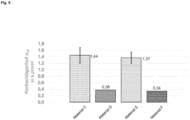
Fig. 5 zeigt die Ergebnisse eines Schlagzähigkeitstests für verschiedene schmelzfähige Materialien M2. -
- 1
- Kunststoffdraht/-filament des schmelzfähigen Materials M1 für das Kunststoffbauteil
- 2
- Kunststoffdraht/-filament des schmelzfähigen Materials M2 für die Stützstruktur
- 3
- Vortrieb
- 4
- Kontaktheizung
- 5
- Düse
- 6
- Kunststoffbauteil
- 7
- Extruder
- 8
- linienartige Auftragung
- 9
- Stützstruktur
- 10
- Bauplattform
- 1'
- Dryblend (thermoplastischer Kunststoff K2 und Weichmacher)
- 2'
- Salz
- 3'
- Dosiereinheiten
- 4'
- Doppelschneckenextruder
- 5'
- extrudiertes Compound
- 6'
- Förderband
- 7'
- Ventilatoren
- 8'
- Granulator
- 9'
- Granulat
- 10'
- Auffangbehälter
- 1"
- Einschneckenextruder
- 2"
- Positionierrollen
- 3"
- Filament
- 4"
- Wasserbad
- 5"
- Abstreiftuch
- 6"
- Laservermessung der Filamente
- 7"
- Abzugsrollen
- 8"
- Filamentspule
- Die folgenden Beispiele dienen der weiteren Erläuterung der vorliegenden Erfindung, ohne jedoch hierauf beschränkt zu sein.
- Mittels einer handelsüblichen 3D-Druckvorrichtung wurden Kunststoffbauteile gefertigt, welche aufgrund ihres Überhangs den Einsatz einer Stützstruktur erforderten. Zum Aufbau der Stützstruktur kamen zwei verschiedene schmelzfähige Materialien M2 zum Einsatz, im Folgenden als Material A und Material B bezeichnet. Die Zusammensetzung der entsprechenden Compounds (in Massenteilen der jeweiligen Komponenten) ist in nachstehender Tabelle 1 wiedergegeben:
Tabelle 1 Massenteile PHBV Massenteile PEG Massenteile NaCl Material A 100 50 100 Material B 100 25 125 - Die Stützstrukturen wurden sodann durch Strangablegen aufgebaut, wobei dies bei einer Ablegegeschwindigkeit von 36 mm/s, einer Düsentemperatur von 190 °C, einer Plattformtemperatur von 75 °C und einer relativen Durchflussrate von etwa 105 % erfolgte. Photographien der so aufgebauten Stützstrukturen sind in
Fig. 4(a) gezeigt, links für Material A und rechts für Material B. Von oben nach unten sind jeweils drei konsekutive Aufnahmen des Aufbauprozesses der Stützstruktur gezeigt. Dabei lässt sich erkennen, dass die Stützstruktur aus dem Material A im Vergleich zu derjenigen aus dem Material B eine inhomogenere Oberflächenstruktur aufwies. Erklärt werden kann dies anhand der niedrigeren Viskosität im Falle des Materials A, bedingt durch den höheren Anteil des Weichmachers in der Zusammensetzung. Wie sich den Photographien ausFig. 4(b) entnehmen lässt, wurde die Oberflächenstruktur letztlich in das herzustellende Kunststoffbauteil übertragen. Trotz der inhomogeneren Oberflächenstruktur ließen sich auch mit der Stützstruktur aus dem Material A noch zufriedenstellende Ergebnisse erzielen. - Um die mechanischen Eigenschaften der Stützstruktur näher zu untersuchen, wurde die Schlagzähigkeit in Abhängigkeit der Zusammensetzung des schmelzfähigen Materials bestimmt. Hierzu kamen vier verschiedene schmelzfähige Materialien M2 zum Einsatz, im Folgenden als Material C, Material D, Material E und Material F bezeichnet. Die Zusammensetzung der entsprechenden Compounds (in Massenteilen der jeweiligen Komponenten) ist in nachstehender Tabelle 2 wiedergegeben:
Tabelle 2 Massenteile PHBV Massenteile PEG Massenteile NaCl Material C 100 40 60 Material D 100 00 42,86 Material E 100 50 100 Material F 100 00 66,67 - Die Ergebnisse sind in
Fig. 5 veranschaulicht. Im Falle der Materialien D und F, welche keinen Weichmacher enthielten, wurde eine vergleichsweise niedrige Kerbschlagarbeit ermittelt. Demgegenüber wurde im Falle der Materialien C und E eine vergleichsweise hohe Kerbschlagarbeit ermittelt. Im Gegensatz zu den Stützstrukturen aus den Materialien D und F brachen die Stützstrukturen aus den Materialien C und E demnach erst bei deutlich höherem Energieeintrag. Zurückzuführen ist dies auf die Anwesenheit des Weichmachers, welcher zu einer Verringerung der Sprödigkeit führte. - Schließlich wurde noch die Löslichkeit der Stützstruktur in Wasser näher untersucht. Hierzu kamen fünf verschiedene schmelzfähige Materialien M2 zum Einsatz, im Folgenden als Material G, Material H, Material I, Material J und Material K bezeichnet. Die Zusammensetzung der entsprechenden Compounds (in Massenteilen der jeweiligen Komponenten) ist in nachstehender Tabelle 3 wiedergegeben:
Tabelle 3 Massenteile PHBV Massenteile PEG Massenteile NaCl Material G 100 50 100 Material H 100 40 60 Material I 100 25 125 Material J 100 11,11 111,11 Material K 100 24 76 - Die jeweiligen Stützstrukturen wurden in demineralisiertes Wasser eingetaucht und darin für insgesamt vier Stunden bei einer Temperatur von 70 °C unter Rühren bei 100 U/min aufbewahrt. Die Auswertung erfolgte über Auswiegen nach dem Trocknen bei Raumtemperatur. Nachstehende Tabelle 4 zeigt die Ergebnisse:
Tabelle 4 mvorher in g mnachher in g mlöslich in g mgelöst in g mgelöst/mlöslich Material G 6,2 3,5 3,7 2,7 73% Material H 5,8 3,8 2,9 2,0 69% Material I 7,3 4,1 4,4 3,2 73% Material J 7,2 4,4 4,0 2,8 70% Material K 7,2 5,6 3,6 1,6 44% - Der lösliche Anteil ergibt sich hierbei aus der Gesamtmenge des Weichmachers und des Salzes. Es zeigt sich, dass in allen Fällen nach vier Stunden ein erheblicher Anteil der Stützstruktur in Wasser aufgelöst war.
- Zusammenfassend lässt sich feststellen, dass durch die Anwesenheit des Weichmachers im schmelzfähigen Material M2 die Sprödigkeit der Stützstruktur, welche vom Zusatz des Salzes herrührt, verringert werden kann, ohne dabei die Funktionsweise der Stützstruktur nachteilig zu beeinflussen.
wobei sich das zusammen mit dem mindestens einen thermoplastischen Kunststoff K2 compoundierte Salz auflöst, sobald es mit dem wässrigen Lösungsmittel in Kontakt kommt, während der mindestens eine thermoplastische Kunststoff K2 nicht in Lösung geht und als poröses Gebilde zurückbleibt.
Claims (12)
- Verfahren zur Herstellung eines Kunststoffbauteiles durch additive Fertigung, umfassend die folgenden Schritte (a) und (b):(a) wiederholtes Ablegen eines schmelzfähigen Materials M1, welches aus mindestens einem thermoplastischen Kunststoff K1 gebildet ist, zum Aufbau eines Kunststoffbauteiles mit vorgegebener Geometrie, wobei während des Aufbaus des Kunststoffbauteiles eine Stützstruktur aus einem schmelzfähigen Material M2 zur Ermöglichung von Überhängen bzw. Hinterschneidungen im Kunststoffbauteil verwendet wird, und(b) Entfernen der Stützstruktur von dem in Schritt (a) aufgebauten Kunststoffbauteil nach dessen Fertigstellung durch Inkontaktbringen mit einem wässrigen Lösungsmittel,wobei das schmelzfähige Material M2 aus mindestens einem thermoplastischen Kunststoff K2, welcher zumindest mit einem Salz und einem Weichmacher compoundiert ist, gebildet ist und wobei in dem schmelzfähigen Material M2, bezogen auf 100 Massenteile der Gesamtmenge des mindestens einen thermoplastischen Kunststoffes K2, 100 bis 150 Massenteile des Salzes und 10 bis 50 Massenteile des Weichmachers vorhanden sind, und
wobei sich das zusammen mit dem mindestens einen thermoplastischen Kunststoff K2 compoundierte Salz auflöst, sobald es mit dem wässrigen Lösungsmittel in Kontakt kommt, während der mindestens eine thermoplastische Kunststoff K2 nicht in Lösung geht und als poröses Gebilde zurückbleibt. - Verfahren nach Anspruch 1, wobei die Stützstruktur in Schritt (a) während des Aufbaus des Kunststoffbauteiles durch wiederholtes Ablegen des schmelzfähigen Materials M2 aufgebaut wird.
- Verfahren nach Anspruch 2, wobei zum Aufbau des Kunststoffbauteiles und der Stützstruktur eine 3D-Druckvorrichtung mit mindestens zwei Extrudern und Düsen verwendet wird, wobei die 3D-Druckvorrichtung sowohl mit einem Filament, Granulat oder Pulver des schmelzfähigen Materials M1 als auch mit einem Filament, Granulat oder Pulver des schmelzfähigen Materials M2 ausgestattet ist.
- Verfahren nach einem der Ansprüche 1 bis 3, wobei der mindestens eine thermoplastische Kunststoff K1 und der mindestens eine thermoplastische Kunststoff K2 identisch sind.
- Verfahren nach einem der Ansprüche 1 bis 4, wobei der mindestens eine thermoplastische Kunststoff K1 aus der Gruppe, bestehend aus Polyestern, Polyamiden, Polyurethanen, Polycarbonaten, Polyketonen und Polyolefinen, ausgewählt und gegebenenfalls ein thermoplastisches Elastomer ist.
- Verfahren nach Anspruch 5, wobei der mindestens eine thermoplastische Kunststoff K1 aus der Gruppe, bestehend aus Polylactid, Acrylnitril-Butadien-Styrol-Copolymer, Acrylnitril-Styrol-Acrylat-Copolymer, Polymethylmethacrylat, Polyetheretherketon und Glykol-modifiziertem Polyethylenterephthalat, ausgewählt ist.
- Verfahren nach einem der Ansprüche 1 bis 6, wobei der mindestens eine thermoplastische Kunststoff K2 aus der Gruppe, bestehend aus Polyhydroxyalkanoaten, insbesondere Poly(3-hydroxybutyrat), Poly(3-hydroxybutyrat-co-3-hydroxyvalerat) und Poly(3-hydroxybutyrat-co-3-hydroxyhexanoat), sowie Polycaprolacton, thermoplastischer Stärke, Polybutylenadipatterephthalat und Polybutylensuccinat, ausgewählt ist.
- Verfahren nach einem der Ansprüche 1 bis 7, wobei das Salz aus der Gruppe, bestehend aus Natriumchlorid, Natriumsulfat, Natriumnitrat, Kaliumchlorid, Kaliumsulfat und Kaliumnitrat, ausgewählt ist.
- Verfahren nach einem der Ansprüche 1 bis 8, wobei der Weichmacher Polyethylenglykol ist.
- Verfahren nach einem der Ansprüche 1 bis 9, wobei der mindestens eine thermoplastische Kunststoff K2 weiter mit einem oder mehreren Additiven, ausgewählt aus der Gruppe, bestehend aus Fließhilfsmitteln, Schlagzähmodifizierern, Keimbildnern und Füllstoffen, compoundiert ist.
- Verfahren nach einem der Ansprüche 1 bis 10, wobei der mindestens eine thermoplastische Kunststoff K2 biologisch abbaubar ist.
- Filament, Granulat oder Pulver des schmelzfähigen Materials M2 zur Verwendung als Stützstruktur in dem Verfahren nach einem der Ansprüche 1 bis 11.
Applications Claiming Priority (1)
| Application Number | Priority Date | Filing Date | Title |
|---|---|---|---|
| DE102022208661.9A DE102022208661A1 (de) | 2022-08-22 | 2022-08-22 | Bedarfsangepasste wasserlösliche Stützstrukturen für die additive Fertigung |
Publications (3)
| Publication Number | Publication Date |
|---|---|
| EP4331811A1 true EP4331811A1 (de) | 2024-03-06 |
| EP4331811B1 EP4331811B1 (de) | 2025-05-28 |
| EP4331811C0 EP4331811C0 (de) | 2025-05-28 |
Family
ID=87760340
Family Applications (1)
| Application Number | Title | Priority Date | Filing Date |
|---|---|---|---|
| EP23192482.0A Active EP4331811B1 (de) | 2022-08-22 | 2023-08-21 | Bedarfsangepasste wasserlösliche stützstrukturen für die additive fertigung |
Country Status (2)
| Country | Link |
|---|---|
| EP (1) | EP4331811B1 (de) |
| DE (1) | DE102022208661A1 (de) |
Citations (3)
| Publication number | Priority date | Publication date | Assignee | Title |
|---|---|---|---|---|
| US6790403B1 (en) * | 1999-04-20 | 2004-09-14 | Stratasys, Inc. | Soluble material and process for three-dimensional modeling |
| US20170217087A1 (en) * | 2016-01-28 | 2017-08-03 | Nozomu Tamoto | Solid freeform fabrication material, solid freeform fabrication material set, and method of manufacturing solid freeform fabrication object |
| US20200254695A1 (en) * | 2017-09-28 | 2020-08-13 | Rhodia Operations | Method for manufacturing a three-dimensional object using dimensionally stable and water soluble polyamide support material |
Family Cites Families (1)
| Publication number | Priority date | Publication date | Assignee | Title |
|---|---|---|---|---|
| WO2017112689A1 (en) * | 2015-12-24 | 2017-06-29 | Stratasys, Inc. | Water soluble support materials for high temperature additive manufacturing applications |
-
2022
- 2022-08-22 DE DE102022208661.9A patent/DE102022208661A1/de not_active Ceased
-
2023
- 2023-08-21 EP EP23192482.0A patent/EP4331811B1/de active Active
Patent Citations (3)
| Publication number | Priority date | Publication date | Assignee | Title |
|---|---|---|---|---|
| US6790403B1 (en) * | 1999-04-20 | 2004-09-14 | Stratasys, Inc. | Soluble material and process for three-dimensional modeling |
| US20170217087A1 (en) * | 2016-01-28 | 2017-08-03 | Nozomu Tamoto | Solid freeform fabrication material, solid freeform fabrication material set, and method of manufacturing solid freeform fabrication object |
| US20200254695A1 (en) * | 2017-09-28 | 2020-08-13 | Rhodia Operations | Method for manufacturing a three-dimensional object using dimensionally stable and water soluble polyamide support material |
Also Published As
| Publication number | Publication date |
|---|---|
| DE102022208661A1 (de) | 2024-02-22 |
| EP4331811B1 (de) | 2025-05-28 |
| EP4331811C0 (de) | 2025-05-28 |
Similar Documents
| Publication | Publication Date | Title |
|---|---|---|
| DE69917910T2 (de) | Verfahren zum Herstellen von wasserlöslichen Elementen | |
| DE69212557T2 (de) | Verfahren zur Herstellung eines stärkehaltigen biologisch abbaubaren Kunststoffmaterials | |
| DE69907224T2 (de) | Bioabbaubare zusammensetzungen von stärke und polysaccharide-estern | |
| DE4117628C2 (de) | Verfahren und Vorrichtung zur Herstellung von Stärkeschmelze sowie nach diesem Verfahren erhältliche Produkte | |
| DE602004011759T3 (de) | Formteile, die ein polyhydroxyalkanoatcopolymer und ein in der umwelt abbaubares thermoplastisches polymer enthalten | |
| EP3898183B1 (de) | Pulverschichtungsverfahren zur fertigung 3d-gedruckter bauteile mit verbesserten mechanischen eigenschaften | |
| DE69306874T2 (de) | Durch Wärme formbare Zusammensetzung, Verfahren zu ihrer Herstellung und ihre Anwendung zur Herstellung von thermogeformten Gegenständen | |
| EP3606999B1 (de) | Biologisch abbaubare folie, transportbeutel enthaltend eine folie, verfahren zur herstellung einer folie und verwendung einer folie | |
| DE102013005568B4 (de) | Verfahren zur Herstellung von Lebensmittelverpackungen und nach diesem Verfahren hergestellte Lebensmittelverpackung | |
| EP3250356B1 (de) | Verfahren zur herstellung eines spritzgussproduktes, entsprechendes spritzgussprodukt sowie verwendung speziell zubereiteter sonnenblumenschalenfasern als additiv | |
| WO1993019124A1 (de) | Thermoplastisch verarbeitbare werkstoffe auf stärkebasis, daraus gewonnene formteile und verfahren zu ihrer herstellung | |
| EP3737519A1 (de) | VERFAHREN ZUM METALLPULVERSPRITZGIEßEN | |
| DE60036845T2 (de) | Aliphatische polyesterzusammensetzung für eine grundmischung und verfahren zur herstellung einer aliphatischen polyesterfolie unter verwendung der zusammensetzung | |
| EP4331811B1 (de) | Bedarfsangepasste wasserlösliche stützstrukturen für die additive fertigung | |
| EP3902661B1 (de) | Compound bzw. folie enthaltend thermoplastische stärke sowie ein thermoplastisches polymer | |
| DE69628532T2 (de) | Bioabbaubare Zusammensetzung, Verfahren und Einrichtung zu ihrer Herstellung | |
| WO2000027611A1 (de) | Verfahren zur herstellung eines stabförmigen verbundkörpers sowie stabförmiger verbundkörper | |
| EP3750686A1 (de) | Wasserlösliche stützstrukturen für das strangablegeverfahren | |
| EP3604184B1 (de) | Verwendung von umweltfreundlichem streugranulat | |
| EP4066807B1 (de) | Urne aus einem biologisch abbaubaren, spritzgussfähigen material, verfahren zu ihrer herstellung und ihre verwendung | |
| DE4429269A1 (de) | Verfahren zur Herstellung von Gegenständen aus thermoplastischer Amylose, Formmasse zur Durchführung des Verfahrens sowie Formteil | |
| DE102019114918A1 (de) | Verfahren zur additiven Herstellung eines zumindest abschnittsweise mit Hohlräumen versehenen porösen Formkörpers | |
| EP4317323A1 (de) | Verfahren zum vernetzen von polysacchariden aus makroalgen zu einem polymerwerkstoff | |
| EP3576800B1 (de) | Knochenersatzmaterialkörper und verfahren zu dessen herstellung | |
| DE102022121548A1 (de) | Verfahren zum Drucken von dreidimensionalen Strukturen mit verringertem Aufarbeitungsaufwand |
Legal Events
| Date | Code | Title | Description |
|---|---|---|---|
| PUAI | Public reference made under article 153(3) epc to a published international application that has entered the european phase |
Free format text: ORIGINAL CODE: 0009012 |
|
| STAA | Information on the status of an ep patent application or granted ep patent |
Free format text: STATUS: THE APPLICATION HAS BEEN PUBLISHED |
|
| AK | Designated contracting states |
Kind code of ref document: A1 Designated state(s): AL AT BE BG CH CY CZ DE DK EE ES FI FR GB GR HR HU IE IS IT LI LT LU LV MC ME MK MT NL NO PL PT RO RS SE SI SK SM TR |
|
| STAA | Information on the status of an ep patent application or granted ep patent |
Free format text: STATUS: REQUEST FOR EXAMINATION WAS MADE |
|
| 17P | Request for examination filed |
Effective date: 20240725 |
|
| RBV | Designated contracting states (corrected) |
Designated state(s): AL AT BE BG CH CY CZ DE DK EE ES FI FR GB GR HR HU IE IS IT LI LT LU LV MC ME MK MT NL NO PL PT RO RS SE SI SK SM TR |
|
| GRAP | Despatch of communication of intention to grant a patent |
Free format text: ORIGINAL CODE: EPIDOSNIGR1 |
|
| STAA | Information on the status of an ep patent application or granted ep patent |
Free format text: STATUS: GRANT OF PATENT IS INTENDED |
|
| INTG | Intention to grant announced |
Effective date: 20250108 |
|
| GRAS | Grant fee paid |
Free format text: ORIGINAL CODE: EPIDOSNIGR3 |
|
| GRAA | (expected) grant |
Free format text: ORIGINAL CODE: 0009210 |
|
| STAA | Information on the status of an ep patent application or granted ep patent |
Free format text: STATUS: THE PATENT HAS BEEN GRANTED |
|
| AK | Designated contracting states |
Kind code of ref document: B1 Designated state(s): AL AT BE BG CH CY CZ DE DK EE ES FI FR GB GR HR HU IE IS IT LI LT LU LV MC ME MK MT NL NO PL PT RO RS SE SI SK SM TR |
|
| REG | Reference to a national code |
Ref country code: GB Ref legal event code: FG4D Free format text: NOT ENGLISH |
|
| REG | Reference to a national code |
Ref country code: CH Ref legal event code: EP |
|
| REG | Reference to a national code |
Ref country code: DE Ref legal event code: R081 Ref document number: 502023001052 Country of ref document: DE Owner name: UNIVERSITAET STUTTGART, KOERPERSCHAFT DES OEFF, DE Free format text: FORMER OWNER: ANMELDERANGABEN UNKLAR / UNVOLLSTAENDIG, 80297 MUENCHEN, DE |
|
| REG | Reference to a national code |
Ref country code: IE Ref legal event code: FG4D Free format text: LANGUAGE OF EP DOCUMENT: GERMAN |
|
| REG | Reference to a national code |
Ref country code: DE Ref legal event code: R096 Ref document number: 502023001052 Country of ref document: DE |
|
| U01 | Request for unitary effect filed |
Effective date: 20250604 |
|
| U07 | Unitary effect registered |
Designated state(s): AT BE BG DE DK EE FI FR IT LT LU LV MT NL PT RO SE SI Effective date: 20250612 |
|
| U20 | Renewal fee for the european patent with unitary effect paid |
Year of fee payment: 3 Effective date: 20250827 |
|
| PG25 | Lapsed in a contracting state [announced via postgrant information from national office to epo] |
Ref country code: ES Free format text: LAPSE BECAUSE OF FAILURE TO SUBMIT A TRANSLATION OF THE DESCRIPTION OR TO PAY THE FEE WITHIN THE PRESCRIBED TIME-LIMIT Effective date: 20250528 |
|
| PG25 | Lapsed in a contracting state [announced via postgrant information from national office to epo] |
Ref country code: GR Free format text: LAPSE BECAUSE OF FAILURE TO SUBMIT A TRANSLATION OF THE DESCRIPTION OR TO PAY THE FEE WITHIN THE PRESCRIBED TIME-LIMIT Effective date: 20250829 Ref country code: NO Free format text: LAPSE BECAUSE OF FAILURE TO SUBMIT A TRANSLATION OF THE DESCRIPTION OR TO PAY THE FEE WITHIN THE PRESCRIBED TIME-LIMIT Effective date: 20250828 |
|
| PG25 | Lapsed in a contracting state [announced via postgrant information from national office to epo] |
Ref country code: PL Free format text: LAPSE BECAUSE OF FAILURE TO SUBMIT A TRANSLATION OF THE DESCRIPTION OR TO PAY THE FEE WITHIN THE PRESCRIBED TIME-LIMIT Effective date: 20250528 |
|
| PG25 | Lapsed in a contracting state [announced via postgrant information from national office to epo] |
Ref country code: HR Free format text: LAPSE BECAUSE OF FAILURE TO SUBMIT A TRANSLATION OF THE DESCRIPTION OR TO PAY THE FEE WITHIN THE PRESCRIBED TIME-LIMIT Effective date: 20250528 |
|
| PG25 | Lapsed in a contracting state [announced via postgrant information from national office to epo] |
Ref country code: RS Free format text: LAPSE BECAUSE OF FAILURE TO SUBMIT A TRANSLATION OF THE DESCRIPTION OR TO PAY THE FEE WITHIN THE PRESCRIBED TIME-LIMIT Effective date: 20250828 |
|
| PG25 | Lapsed in a contracting state [announced via postgrant information from national office to epo] |
Ref country code: IS Free format text: LAPSE BECAUSE OF FAILURE TO SUBMIT A TRANSLATION OF THE DESCRIPTION OR TO PAY THE FEE WITHIN THE PRESCRIBED TIME-LIMIT Effective date: 20250928 |
|
| PG25 | Lapsed in a contracting state [announced via postgrant information from national office to epo] |
Ref country code: SM Free format text: LAPSE BECAUSE OF FAILURE TO SUBMIT A TRANSLATION OF THE DESCRIPTION OR TO PAY THE FEE WITHIN THE PRESCRIBED TIME-LIMIT Effective date: 20250528 |
|
| PG25 | Lapsed in a contracting state [announced via postgrant information from national office to epo] |
Ref country code: CZ Free format text: LAPSE BECAUSE OF FAILURE TO SUBMIT A TRANSLATION OF THE DESCRIPTION OR TO PAY THE FEE WITHIN THE PRESCRIBED TIME-LIMIT Effective date: 20250528 |
|
| PG25 | Lapsed in a contracting state [announced via postgrant information from national office to epo] |
Ref country code: SK Free format text: LAPSE BECAUSE OF FAILURE TO SUBMIT A TRANSLATION OF THE DESCRIPTION OR TO PAY THE FEE WITHIN THE PRESCRIBED TIME-LIMIT Effective date: 20250528 |
|
| PG25 | Lapsed in a contracting state [announced via postgrant information from national office to epo] |
Ref country code: MC Free format text: LAPSE BECAUSE OF FAILURE TO SUBMIT A TRANSLATION OF THE DESCRIPTION OR TO PAY THE FEE WITHIN THE PRESCRIBED TIME-LIMIT Effective date: 20250528 |
|
| PLBE | No opposition filed within time limit |
Free format text: ORIGINAL CODE: 0009261 |
|
| STAA | Information on the status of an ep patent application or granted ep patent |
Free format text: STATUS: NO OPPOSITION FILED WITHIN TIME LIMIT |
|
| REG | Reference to a national code |
Ref country code: CH Ref legal event code: L10 Free format text: ST27 STATUS EVENT CODE: U-0-0-L10-L00 (AS PROVIDED BY THE NATIONAL OFFICE) Effective date: 20260409 |
|
| 26N | No opposition filed |
Effective date: 20260303 |
|
| PG25 | Lapsed in a contracting state [announced via postgrant information from national office to epo] |
Ref country code: IE Free format text: LAPSE BECAUSE OF NON-PAYMENT OF DUE FEES Effective date: 20250821 |