EP4331799A1 - Individual zone tension control - Google Patents
Individual zone tension control Download PDFInfo
- Publication number
- EP4331799A1 EP4331799A1 EP23192072.9A EP23192072A EP4331799A1 EP 4331799 A1 EP4331799 A1 EP 4331799A1 EP 23192072 A EP23192072 A EP 23192072A EP 4331799 A1 EP4331799 A1 EP 4331799A1
- Authority
- EP
- European Patent Office
- Prior art keywords
- textile material
- tensioner
- tension
- shaped portion
- signal
- Prior art date
- Legal status (The legal status is an assumption and is not a legal conclusion. Google has not performed a legal analysis and makes no representation as to the accuracy of the status listed.)
- Pending
Links
Images




Classifications
-
- B—PERFORMING OPERATIONS; TRANSPORTING
- B65—CONVEYING; PACKING; STORING; HANDLING THIN OR FILAMENTARY MATERIAL
- B65H—HANDLING THIN OR FILAMENTARY MATERIAL, e.g. SHEETS, WEBS, CABLES
- B65H23/00—Registering, tensioning, smoothing or guiding webs
- B65H23/04—Registering, tensioning, smoothing or guiding webs longitudinally
- B65H23/044—Sensing web tension
-
- B—PERFORMING OPERATIONS; TRANSPORTING
- B29—WORKING OF PLASTICS; WORKING OF SUBSTANCES IN A PLASTIC STATE IN GENERAL
- B29B—PREPARATION OR PRETREATMENT OF THE MATERIAL TO BE SHAPED; MAKING GRANULES OR PREFORMS; RECOVERY OF PLASTICS OR OTHER CONSTITUENTS OF WASTE MATERIAL CONTAINING PLASTICS
- B29B11/00—Making preforms
- B29B11/14—Making preforms characterised by structure or composition
- B29B11/16—Making preforms characterised by structure or composition comprising fillers or reinforcement
-
- B—PERFORMING OPERATIONS; TRANSPORTING
- B29—WORKING OF PLASTICS; WORKING OF SUBSTANCES IN A PLASTIC STATE IN GENERAL
- B29C—SHAPING OR JOINING OF PLASTICS; SHAPING OF MATERIAL IN A PLASTIC STATE, NOT OTHERWISE PROVIDED FOR; AFTER-TREATMENT OF THE SHAPED PRODUCTS, e.g. REPAIRING
- B29C70/00—Shaping composites, i.e. plastics material comprising reinforcements, fillers or preformed parts, e.g. inserts
- B29C70/04—Shaping composites, i.e. plastics material comprising reinforcements, fillers or preformed parts, e.g. inserts comprising reinforcements only, e.g. self-reinforcing plastics
- B29C70/28—Shaping operations therefor
- B29C70/54—Component parts, details or accessories; Auxiliary operations, e.g. feeding or storage of prepregs or SMC after impregnation or during ageing
- B29C70/56—Tensioning reinforcements before or during shaping
Definitions
- the present disclosure relates generally to controlling individual tensioning of textile material in respective zones when forming a preform.
- Composite bodies are utilized in various industries, including the aerospace industry.
- the composite bodies start with a preform that is formed using layers of textile material.
- textile material naturally arrives at the preform forming machine with varying tensions causing variation in the final preform product.
- a system for controlling tension on textile material used in forming a preform includes a sensor; and a controller, where the controller is configured to: receive a signal, from the sensor, indicative of a compressive force applied by the textile material feeding into the system; determine whether the compressive force is within range of a setpoint of the tension for the textile material; and responsive to the compressive force being outside the range, send a command of at least one of an increase or a decrease of the tension on the textile material.
- the senor is at least one of a load cell or a strain gauge. In various embodiments, the sensor is located between a front bar and a back bar of a forming machine and the compressive force is the textile material acting on at least one of the back bar, the front bar, a structure associated with the back bar, or a structure associated with the front bar.
- the system further includes a double bar tensioner, where the tension is provided by the double bar tensioner.
- the double bar tensioner comprises a first cylindrically shaped portion and a second cylindrically shaped portion, where a first end of the first cylindrically shaped portion and a first end of the second cylindrically shaped portion are coupled to a first side structure, and where a second end of the first cylindrically shaped portion and a second end of the second cylindrically shaped portion are coupled to a second side structure.
- the system further includes a tensioner motor, where the double bar tensioner is coupled to the tensioner motor and where the tensioner motor rotates the double bar tensioner along a central axis between the first cylindrically shaped portion and the second cylindrically shaped portion to either increase or decrease the tension on the textile material.
- rotating the double bar tensioner clockwise along the central axis increases the tension on the textile material and rotating the double bar tensioner counterclockwise along the central axis decreases the tension on the textile material.
- rotating the double bar tensioner counterclockwise along the central axis increases the tension on the textile material and rotating the double bar tensioner clockwise along the central axis decreases the tension on the textile material.
- the system further includes a signal amplifier, where the signal is an analog signal and where the signal amplifier amplifies the analog signal prior to being received by the controller.
- the system further includes a digital-to-analog converter; and a signal amplifier, where the signal is a digital signal, where the digital-to-analog converter converts the digital signal to an analog signal, and where signal amplifier amplifies the analog signal prior to being received by the controller.
- the method includes receiving, by a controller, a signal indicative of a compressive force applied by the textile material feeding into a forming machine; determining, by the controller, whether the compressive force is within range of a setpoint of a tension for the textile material; and responsive to the compressive force being outside the range, sending, by the controller, a command of at least one of an increase or a decrease of the tension on the textile material.
- the signal is received from a sensor and the sensor is at least one of a load cell or a strain gauge.
- the sensor is located between a front bar and a back bar of the forming machine and the compressive force is the textile material acting on at least one of the back bar, the front bar, a structure associated with the back bar, or a structure associated with the front bar.
- the tension is provided by a double bar tensioner.
- the double bar tensioner comprises a first cylindrically shaped portion and a second cylindrically shaped portion, where a first end of the first cylindrically shaped portion and a first end of the second cylindrically shaped portion are coupled to a first side structure, and where a second end of the first cylindrically shaped portion and a second end of the second cylindrically shaped portion are coupled to a second side structure.
- the double bar tensioner is coupled to a tensioner motor, where the tensioner motor rotates the double bar tensioner along a central axis between the first cylindrically shaped portion and the second cylindrically shaped portion to either increase or decrease the tension on the textile material.
- rotating the double bar tensioner clockwise along the central axis increases the tension on the textile material and rotating the double bar tensioner counterclockwise along the central axis decreases the tension on the textile material. In various embodiments, rotating the double bar tensioner counterclockwise along the central axis increases the tension on the textile material and rotating the double bar tensioner clockwise along the central axis decreases the tension on the textile material.
- the signal is an analog signal and the analog signal is amplified prior to being received by the controller.
- the signal is a digital signal and the digital signal is converted to an analog signal and then amplified prior to being received by the controller.
- references to "a,” “an,” or “the” may include one or more than one and that reference to an item in the singular may also include the item in the plural. Further, all ranges may include upper and lower values and all ranges and ratio limits disclosed herein may be combined.
- textile material may pass over a set of rollers designed to keep the textile material at a same tension as the preform material travels through the preform forming machinery.
- textile material wrapping may occur where the textile material wraps around the rollers causing tears in the textile material and thereby creating poor quality preforms, breaking rollers, etc.
- such rollers have been removed and the textile material is routed through a series of directional changes to provide tensioning.
- the textile material properties may change. The effects of changing the routing are amplified if an inlet roller is in an undesirable position while the preform forming machinery is running.
- an outlet roller may pull the textile material through the preform forming machinery without the inlet rollers grabbing the textile material. Also, if the tension on the textile material is greater than the gripping force of the inlet roller, the textile material may slip between the inlet roller changing a needling effect on the textile material as it passes through the loom of the preform forming machinery.
- tensioning may be applied to all textile materials used in forming the preform at a predetermined setpoint, which fails to account for differences and variation in each of the textile materials.
- the systems and methods disclosed herein monitor a compressive force applied by each textile material as the textile material is pulled into the preform forming machinery.
- the systems and methods analyze the compressive force of each textile material and apply individual tensioning, where desired, to account for variations in the textile material so that the materials are pulled into the preform forming machinery thereby reducing variations in the formed preform.
- aircraft wheel braking assembly such as may be found on an aircraft, is illustrated.
- aircraft wheel braking assembly 10 may include a bogie axle 12, a wheel 14 including a hub 16 and a wheel well 18, a web 20, a torque take-out assembly 22, one or more torque bars 24, a wheel rotational axis 26, a wheel well recess 28, an actuator 30, multiple brake rotors 32, multiple brake stators 34, a pressure plate 36, an end plate 38, a heat shield 40, multiple heat shield sections 42, multiple heat shield carriers 44, an air gap 46, multiple torque bar bolts 48, a torque bar pin 50, a wheel web hole 52, multiple heat shield fasteners 53, multiple rotor lugs 54, and multiple stator slots 56.
- the various components of aircraft wheel braking assembly 10 may be subjected to the application of compositions and methods for protecting the components from oxidation.
- Brake disks e.g., interleaved rotors 32 and stators 34
- Rotors 32 are secured to torque bars 24 for rotation with wheel 14, while stators 34 are engaged with torque take-out assembly 22.
- At least one actuator 30 is operable to compress interleaved rotors 32 and stators 34 for stopping the aircraft.
- actuator 30 is shown as a hydraulically actuated piston, but many types of actuators are suitable, such as an electromechanical actuator.
- Pressure plate 36 and end plate 38 are disposed at opposite ends of the interleaved rotors 32 and stators 34.
- Rotors 32 and stators 34 can comprise any material suitable for friction disks, including ceramics or carbon materials, such as a carbon/carbon composite.
- Torque take-out assembly 22 is secured to a stationary portion of the landing gear truck such as a bogie beam or other landing gear strut, such that torque take-out assembly 22 and stators 34 are prevented from rotating during braking of the aircraft.
- Carbon-carbon composites (also referred to herein as composite structures, composite substrates, and carbon-carbon composite structures, interchangeably) in the friction disks may operate as a heat sink to absorb large amounts of kinetic energy converted to heat during slowing of the aircraft.
- Heat shield 40 may reflect thermal energy away from wheel well 18 and back toward rotors 32 and stators 34. Heat shield 40 is attached to wheel 14 and is concentric with wheel well 18. Individual heat shield sections 42 may be secured in place between wheel well 18 and rotors 32 by respective heat shield carriers 44 fixed to wheel well 18. Air gap 46 is defined annularly between heat shield segments 42 and wheel well 18.
- Torque bars 24 and heat shield carriers 44 can be secured to wheel 14 using bolts or other fasteners.
- Torque bar bolts 48 can extend through a hole formed in a flange or other mounting surface on wheel 14.
- Each torque bar 24 can optionally include at least one torque bar pin 50 at an end opposite torque bar bolts 48, such that torque bar pin 50 can be received through wheel web hole 52 in web 20.
- Heat shield sections 42 and respective heat shield carriers 44 can then be fastened to wheel well 18 by heat shield fasteners 53.
- Fibrous preform 110 may comprise a plurality of sheets of fabric 100 stacked together. Sheets of fabric 100 may all be oriented in a common direction so that their respective plurality of fibers (i.e., first plurality of fibers 102, second plurality of fibers 104, third plurality of fibers 106, and/or fourth plurality of fibers 108) are commonly oriented, or may be alternatingly rotated so that their respective plurality of fibers extend in different direction in a crisscross pattern.
- first plurality of fibers 102, second plurality of fibers 104, third plurality of fibers 106, and/or fourth plurality of fibers 108 are commonly oriented, or may be alternatingly rotated so that their respective plurality of fibers extend in different direction in a crisscross pattern.
- Fibrous preform 110 may comprise one or more layers of a non-woven fabric, one or more layers of a woven fabric (e.g., plain weave, 5-harness satin weave, 8-harness satin weave, etc.), or combinations thereof.
- Fibrous preform 110 may comprise PAN or OPF fibers extending in three directions and leaving a plurality of pores or open spaces and may be prepared for shape-forming, compression, and carbonization.
- fibrous preform 110 is formed by stacking layers of PAN or OPF fibers and superimposing the layers (e.g., by stacking sheets of fabric 100). The layers may be needled perpendicularly to each other (i.e., along the Z-direction) with barbed, textile needles or barbless, structuring needles.
- the layers are needled at an angle of between 0° and 60° (e.g., 0°, 30°, 45°, and/or 60°) with respect to the Z-direction to each other.
- the needling process generates a series of z-fibers through fibrous preform 110 that extend perpendicularly to the fibrous layers.
- the z-fibers are generated through the action of the needles pushing fibers from within the layer (x-y or in-plane) and reorienting them in the z-direction (through-thickness). Needling of the fibrous preform may be done as one or more layers are added to the stack or may be done after the entire stack of layers is formed.
- the needles may also penetrate through only a portion of fibrous preform 110, or may penetrate through the entire fibrous preform 110.
- resins are sometimes added to fibrous preform 110 by either injecting the resin into the preform following construction or coating the fibers or layers prior to forming the fibrous preform 110.
- the needling process may take into account needling parameters optimized to maintain fiber orientation, minimize in-plane fiber damage, and maintain target interlaminar properties.
- the fibrous preform 110 may be both compressed to higher fiber volume ratio and formed to shape in a single-step shape-forming process; though it is also contemplated that in various embodiments the fibrous preform 110 is compressed and shape formed without undergoing the needling process.
- Fibrous preform 200 may be employed to form a leading-edge surface or other aerospace component, as described above. Although illustrated as comprising a round shape, it is contemplated and understood that fibrous preform 200 may comprise any desired shape, such as square, rectangular, polygonal, ovular, circular, or any other shape as desired. Fibrous preform 200 may comprise a stacked plurality of textile layers 202.
- Each textile layer in the textile layers 202 has a first dimension in the thickness direction (e.g., as measured along the direction of the Y-axis) that may be substantially less than the dimensions of the textile layer in the textile layers 202 in the lateral and transverse directions (e.g., as measured along directions of the X-axis and Z-axis, respectively).
- textile layers 202 include woven, braided, entangled, or knitted carbon fibers.
- one or more of the textile layers 202 may comprise silicon carbide fibers or boron fibers.
- one or more of the textile layers 202 may comprise carbon fibers in an open weave pattern (i.e., a weave where there is increased distance between the warp tows and between the weft tows).
- one or more of the textile layers 202 may comprise stretch-broken carbon fibers. Stretch-broken fibers are generally made by stretching a fiber bundle until the individual fibers break or fracture into multiple fragments.
- Stretch-broken fibers may take a form of aligned discontinuous fiber. Stretch-broken fibers provide flexibility to form complex shapes while maintaining comparable strength and stiffness to that of continuous fibers.
- the carbon fibers may be derived from polyacrylonitrile (PAN), rayon (synthetic fiber derived from cellulose), oxidized polyacrylonitrile fiber (OPF), carbon pitch, or the like.
- the starting fiber may be pre-oxidized PAN or fully carbonized commercial carbon fiber.
- the textile layers 202 may be formed or cut having any desired shape or form.
- textile layers 202 may have any desired shape such as, for example, a polygon, circular, triangular, square, rectangular, pentagonal, hexagonal, octagonal, among others.
- textile layers 202 and fibrous preform 200 may have a generally planar geometry or a non-planar geometry (e.g., a complex 3D shape).
- Fibrous preform 200 is a lay-up of textile layers 202.
- fibrous preform 200 includes one or more ceramic particle layers 204.
- Each ceramic particle layer in the one or more ceramic particle layers 204 is located between a pair of textile layers 202 adjacent to one another.
- ceramic particle layers 204 may be comprised of silicon carbide particles.
- a range of particle sizes (or powder sizes) may be employed in the ceramic powders used to fabricate the ceramic particle layers 204.
- a silicon carbide powder between 100 grit and 500 grit may be selected for ceramic particle layers 204.
- a silicon carbide powder between 200 grit and 500 grit may be selected for ceramic particle layers 204.
- a silicon carbide powder between 250 grit and 450 grit may be selected for ceramic particle layers 204.
- a silicon carbide powder between 400 grit and 500 grit may be selected for ceramic particle layers 204.
- the silicon carbide particles may have an average particle size between about 35 micrometers ( ⁇ m) and about 163 ⁇ m, between about 35 ⁇ m and about 85 ⁇ m, between about 39 ⁇ m and about 68 ⁇ m, and/or between about 35 ⁇ m and about 44 ⁇ m (i.e., between about 0.00137 inches and about 0.0064 inches, between about 0.00137 inches and about 0.0033 inches, between about 0.0015 inches and about 0.00267 inches, and/or between about 0.00137 inches and about 0.0017 inches).
- the term "about” means plus or minus ten percent of the associated value.
- FIG. 3 a system for controlling individual tensions of textile material, such as textile layers 202 of FIG. 2B , in respective zones when forming a preform is illustrated.
- the system 300 may include a set of sensors 302, a set of signal amplifiers 304, a controller 306, and a set of tensioner motors 308.
- each textile material is routed through a respective double bar tensioner coupled to respective one of the set of tensioner motors 308.
- the system uses a positioning frame as a cantilever such that each textile material changes direction just prior to entering the preform forming machine by an angle that allows each textile material to compress an associated one of the set of sensors 302.
- each sensor in the set of sensors 302 may be a load cell, strain gauge, among others.
- the angle may be between 75 degrees and 105 degrees. In various embodiments, the angle may be within 85 degrees and 95 degrees. In various embodiments, the angle may be substantially 90 degrees.
- the terms “substantially,” “about,” or “approximately” as used herein represent an amount close to the stated amount that still performs a desired function or achieves a desired result. For example, the term “substantially,” “about,” or “approximately” may refer to an amount that is within 5 degrees, within 3 degrees, within 2 degrees, or within 1 degree of a stated amount or value.
- the textile material is pulled into the preform forming machinery by an inlet roller.
- the textile material passes over a front bar or a structure associated with the front bar at the previously described angle compressing the front bar toward a back bar.
- the textile material passes over the back bar or a structure associated with the back bar at the previously described angle compressing the back bar toward the front bar.
- an associated sensor in the set of sensors 302 is located between the front bar and the back bar.
- the sensor in the set of sensors 302 when a desired compressive force is detected, sends a signal to a respective signal amplifier in the set of signal amplifiers 304.
- a desired compressive force may be between 10 and 200 pounds (lbs.). In various embodiments, the desired compressive force may be between 30 and 150 pounds (lbs.). In various embodiments, the desired compressive force may be between 50 and 100 pounds (lbs.). In various embodiments, the desired compressive force may be between 70 and 80 pounds (lbs.). In various embodiments, each signal amplifier in the set of signal amplifiers 304 amplifies or converts the signal received from the respective sensor of the set of sensors 302 into a signal recognizable by the controller 306.
- the controller 306 may include a logic device such as one or more of a central processing unit (CPU), an accelerated processing unit (APU), a digital signal processor (DSP), a field programmable gate array (FPGA), an application specific integrated circuit (ASIC), or the like.
- the controller 306 may further include any non-transitory memory known in the art.
- the memory may store instructions usable by the controller 306 to perform operations as described herein.
- the controller 306 is an analog controller and where the received signal is an analog signal, the signal amplifier amplifies the signal recognizable by the controller 306.
- the signal amplifier may include a digital-to-analog converter that converts the digital signal to an analog signal and then the signal amplifier amplifies the signal recognizable by the controller 306.
- the controller 306 is a digital controller and the receive signal is a digital signal
- the signal amplifier may be omitted and the digital signal is sent directly to the controller 306.
- an analog-to-digital converter may be provided that converts the analog signal to a digital signal that is then sent to the controller 306.
- the controller 306 compares the received signal to a predetermined tension setpoint. In various embodiments, the controller 306 utilizes respective tension setpoints for each textile material that is used to form the preform. In that regard, in various embodiments, one tension setpoint of one textile material may differ from another tension setpoint of another textile material. Likewise, in various embodiments, the tension setpoint of one textile material may be the same as a tension setpoint of another textile material. In various embodiment, if the controller 306 determines that the received signal fails to be within a range of the associated tension setpoint, then the controller sends a signal to the associated tensioner motor in the set of tensioner motors 308 to either increase tension or decrease tension using the associated double bar tensioner.
- the tensioner motor may rotate the associated double bar tensioner along a central axis in a clockwise direction to increase tension and in a counterclockwise direction to decrease tension, depending on implementation. In various embodiment, the tensioner motor may rotate the associated double bar tensioner along the central axis in a counterclockwise direction to increase tension and in a clockwise direction to decrease tension, depending on implementation.
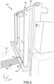
- a front structure 400 of a preform forming machine is illustrated.
- the front structure 400 along the x-axis, includes a cantilever carriage 402 mounted on support structure 404.
- the textile material 406 exits the front structure 400 at the bottom where the textile material 406 changes direction by the previously described angle around a lower structure, i.e., a circular bar 502, illustrated in FIG. 5 , associated with the cantilever carriage 402, such that the textile material 406 travels in a downward direction, i.e., a negative y-direction, around the lower structure, and then in a negative x-direction after changing direction, as indicated by arrow 412.
- a compression force is applied by moving the lower portion of the cantilever carriage 402 and the back bar 408 mounted to the cantilever carriage 402 toward a front bar 410.
- sensor 414 is mounted between the back bar 408 and, as the bottom of the cantilever carriage 402 is forced forward by the textile material 406 toward the front bar 410, the sensor 414 detects the compressive force which is then sent to a controller, such as controller 306 through signal amplifier 304 shown in FIG. 3 , as a signal.
- the signal may be either an analog signal or a digital signal.
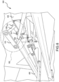
- FIG. 5 a portion of the front structure 400 of a preform forming machine is illustrated.
- the textile material 406 passes the back bar 408 or, as depicted, a circular bar 502 associated with the back bar 408, cantilever carriage 402, to which both the back bar 408 and the circular bar 502 are coupled, traverses toward front bar 410 applying a compressive force to the front bar 410, which is detected by sensor 414 mounted between the back bar 408 and the front bar 410.
- the compressive force is then sent to a controller as a signal.
- sensor 412 measures a horizontal stress force.
- the signal may be either an analog signal or a digital signal.
- a tensioning mechanism 600 of a preform forming machine is illustrated.
- the textile material 406 is routed through a respective double bar tensioner 602 coupled to a respective tensioner motor 604, such as one of the set of tensioner motors 308 of FIG. 3 .
- the double bar tensioner 602 includes a first cylindrically shaped portion 606 and a second cylindrically shaped portion 608.
- a first end of the first cylindrically shaped portion 606 and a first end of the second cylindrically shaped portion 608 are coupled to a first side structure 610.
- a second end of the first cylindrically shaped portion 606 and a second end of the second cylindrically shaped portion 608 are coupled to a second side structure 612.
- the first cylindrically shaped portion 606 and the second cylindrically shaped portion 608 are separated by a first distance.
- the first side structure 610 and the second side structure 612 are separated by a second distance.
- the first cylindrically shaped portion 606 and the second cylindrically shaped portion 608 are substantially perpendicular to the first side structure 610 and the second side structure 612.
- the term “substantially,” as used herein, represents an amount close to the stated amount that still performs a desired function or achieves a desired result.
- the term “substantially” may refer to an amount that is within 10% of, within 5% of, within 1% of, within 0.1% of, and within 0.01% of a stated amount or value.
- tensioner motor 604 may be mounted to the preform forming machine substantially horizontally. In various embodiments, tensioner motor 604 may be mounted to the preform forming machine substantially vertically. In various embodiments, tensioner motor 604 may be mounted to the preform forming machine at an angle that differs from a horizontal or vertical angle. In various embodiments, as illustrated, the tensioner motor 604 may be coupled to an outside of the second side structure 612 of the double bar tensioner 602 such that the tensioner motor 604 is at substantially a 90-degree angle to the second side structure 612.
- the tensioner motor 604 may be coupled to an outside of the second side structure 612 of the double bar tensioner 602 such that the tensioner motor 604 is at substantially a 180-degree angle to the second side structure 612. In various embodiments, tensioner motor 604 may be coupled to an outside of the second side structure 612 of the double bar tensioner 602 at substantially a center 614 of the second side structure 612.
- the tensioner motor 604 may rotate the double bar tensioner 602 in a clockwise direction along a central axis between the first cylindrically shaped portion 606 and the second cylindrically shaped portion 608 to increase tension and in a counterclockwise direction to decrease tension, depending on implementation.
- the tensioner motor 604 in response to the controller sending a signal to the tensioner motor 604 to either increase tension or decrease tension using the associated double bar tensioner, may rotate the double bar tensioner 602 in a counterclockwise direction to increase tension and in a clockwise direction to decrease tension, depending on implementation.
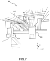
- tensioner motor 604 may be mounted to the preform forming machine substantially horizontally, i.e., in an x direction. In various embodiments, as illustrated, tensioner motor 604 may be mounted to the preform forming machine substantially vertically, i.e., in a y-direction. In various embodiments, tensioner motor 604 may be mounted to the preform forming machine at an angle that differs from a horizontal or vertical angle.
- the tensioner motor 604 may be coupled to an outside of the second side structure 612 of the double bar tensioner 602 such that the tensioner motor 604 is at substantially a 90-degree angle to the second side structure 612. In various embodiments, the tensioner motor 604 may be coupled to an outside of the second side structure 612 of the double bar tensioner 602 such that the tensioner motor 604 is at substantially a 180-degree angle to the second side structure 612.
- FIG. 8 a method for tensioning textile material being fed into a preform forming machine is illustrated.
- the method 800 is described with reference to elements shown in FIGS. 1 thru 7 .
- the system 300 monitors a set of compressive forces induced on a set of sensors 302 associated with a set of textile material 406 feeds passing around a structure associated with the preform forming machine.
- the system 300 evaluates the one or more signals to determine whether the received signal within a range of an associated tension setpoint.
- the system 300 may send a command to a respective tensioner motor 308, 604 to rotate a respective double bar tensioner 602 to increase tension on the associated textile material 406.
- the system 300 may send a command to a respective tensioner motor 308, 604 to rotate a respective double bar tensioner 602 to decrease tension on the associated textile material 406.
- references to "one embodiment,” “an embodiment,” “various embodiments,” etc. indicate that the embodiment described may include a particular feature, structure, or characteristic, but every embodiment may not necessarily include the particular feature, structure, or characteristic. Moreover, such phrases are not necessarily referring to the same embodiment. Further, when a particular feature, structure, or characteristic is described in connection with an embodiment, it is submitted that it is within the knowledge of one skilled in the art to affect such feature, structure, or characteristic in connection with other embodiments whether or not explicitly described. After reading the description, it will be apparent to one skilled in the relevant art(s) how to implement the disclosure in alternative embodiments.
- Numbers, percentages, or other values stated herein are intended to include that value, and also other values that are about or approximately equal to the stated value, as would be appreciated by one of ordinary skill in the art encompassed by various embodiments of the present disclosure.
- a stated value should therefore be interpreted broadly enough to encompass values that are at least close enough to the stated value to perform a desired function or achieve a desired result.
- the stated values include at least the variation to be expected in a suitable industrial process, and may include values that are within 10%, within 5%, within 1%, within 0.1%, or within 0.01% of a stated value.
- the terms “substantially,” “about,” or “approximately” as used herein represent an amount close to the stated amount that still performs a desired function or achieves a desired result.
- the term “substantially,” “about,” or “approximately” may refer to an amount that is within 10% of, within 5% of, within 1% of, within 0.1 % of, and within 0.01% of a stated amount
Landscapes
- Engineering & Computer Science (AREA)
- Mechanical Engineering (AREA)
- Chemical & Material Sciences (AREA)
- Composite Materials (AREA)
- Moulding By Coating Moulds (AREA)
Abstract
Description
- The present disclosure relates generally to controlling individual tensioning of textile material in respective zones when forming a preform.
- Composite bodies are utilized in various industries, including the aerospace industry. The composite bodies start with a preform that is formed using layers of textile material. When running through the preform forming machine, textile material naturally arrives at the preform forming machine with varying tensions causing variation in the final preform product.
- According to various embodiments of the present disclosure, a system for controlling tension on textile material used in forming a preform is provided. The system includes a sensor; and a controller, where the controller is configured to: receive a signal, from the sensor, indicative of a compressive force applied by the textile material feeding into the system; determine whether the compressive force is within range of a setpoint of the tension for the textile material; and responsive to the compressive force being outside the range, send a command of at least one of an increase or a decrease of the tension on the textile material.
- In various embodiments, the sensor is at least one of a load cell or a strain gauge. In various embodiments, the sensor is located between a front bar and a back bar of a forming machine and the compressive force is the textile material acting on at least one of the back bar, the front bar, a structure associated with the back bar, or a structure associated with the front bar.
- In various embodiments, the system further includes a double bar tensioner, where the tension is provided by the double bar tensioner. In various embodiments, the double bar tensioner comprises a first cylindrically shaped portion and a second cylindrically shaped portion, where a first end of the first cylindrically shaped portion and a first end of the second cylindrically shaped portion are coupled to a first side structure, and where a second end of the first cylindrically shaped portion and a second end of the second cylindrically shaped portion are coupled to a second side structure.
- In various embodiments, the system further includes a tensioner motor, where the double bar tensioner is coupled to the tensioner motor and where the tensioner motor rotates the double bar tensioner along a central axis between the first cylindrically shaped portion and the second cylindrically shaped portion to either increase or decrease the tension on the textile material. In various embodiments, rotating the double bar tensioner clockwise along the central axis increases the tension on the textile material and rotating the double bar tensioner counterclockwise along the central axis decreases the tension on the textile material. In various embodiments, rotating the double bar tensioner counterclockwise along the central axis increases the tension on the textile material and rotating the double bar tensioner clockwise along the central axis decreases the tension on the textile material.
- In various embodiments, the system further includes a signal amplifier, where the signal is an analog signal and where the signal amplifier amplifies the analog signal prior to being received by the controller. In various embodiments, the system further includes a digital-to-analog converter; and a signal amplifier, where the signal is a digital signal, where the digital-to-analog converter converts the digital signal to an analog signal, and where signal amplifier amplifies the analog signal prior to being received by the controller.
- Also disclose herein is a method for controlling tension on textile material used in forming a product. The method includes receiving, by a controller, a signal indicative of a compressive force applied by the textile material feeding into a forming machine; determining, by the controller, whether the compressive force is within range of a setpoint of a tension for the textile material; and responsive to the compressive force being outside the range, sending, by the controller, a command of at least one of an increase or a decrease of the tension on the textile material.
- In various embodiments, the signal is received from a sensor and the sensor is at least one of a load cell or a strain gauge. In various embodiments, the sensor is located between a front bar and a back bar of the forming machine and the compressive force is the textile material acting on at least one of the back bar, the front bar, a structure associated with the back bar, or a structure associated with the front bar.
- In various embodiments, the tension is provided by a double bar tensioner. In various embodiments, the double bar tensioner comprises a first cylindrically shaped portion and a second cylindrically shaped portion, where a first end of the first cylindrically shaped portion and a first end of the second cylindrically shaped portion are coupled to a first side structure, and where a second end of the first cylindrically shaped portion and a second end of the second cylindrically shaped portion are coupled to a second side structure. In various embodiments, the double bar tensioner is coupled to a tensioner motor, where the tensioner motor rotates the double bar tensioner along a central axis between the first cylindrically shaped portion and the second cylindrically shaped portion to either increase or decrease the tension on the textile material. In various embodiments, rotating the double bar tensioner clockwise along the central axis increases the tension on the textile material and rotating the double bar tensioner counterclockwise along the central axis decreases the tension on the textile material. In various embodiments, rotating the double bar tensioner counterclockwise along the central axis increases the tension on the textile material and rotating the double bar tensioner clockwise along the central axis decreases the tension on the textile material.
- In various embodiments, the signal is an analog signal and the analog signal is amplified prior to being received by the controller. In various embodiments, the signal is a digital signal and the digital signal is converted to an analog signal and then amplified prior to being received by the controller.
-
-
FIG. 1 illustrates a cross sectional view of an aircraft wheel braking assembly, in accordance with various embodiments. -
FIG. 2A illustrates a perspective of fibrous preform, in accordance with various embodiments. -
FIG. 2B illustrates a fibrous preform, in accordance with various embodiments. -
FIG. 3 illustrates a system for controlling individual tensions of textile material in respective zones when forming a preform, in accordance with various embodiments. -
FIG. 4 illustrates a front structure of a preform forming machine, in accordance with various embodiments. -
FIG. 5 illustrates a portion of the front structure of a preform forming machine, in accordance with various embodiments. -
FIG. 6 illustrates a tensioning mechanism of a preform forming machine, in accordance with various embodiments. -
FIG. 7 illustrates a tensioning mechanism of a preform forming machine, in accordance with various embodiments. -
FIG. 8 illustrates a method for tensioning textile material being fed into a preform forming machine, in accordance with various embodiments. - The following detailed description of various embodiments herein makes reference to the accompanying drawings, which show various embodiments by way of illustration. While these various embodiments are described in sufficient detail to enable those skilled in the art to practice the disclosure, it should be understood that other embodiments may be realized and that changes may be made without departing from the scope of the disclosure. Thus, the detailed description herein is presented for purposes of illustration only and not of limitation. Furthermore, any reference to singular includes plural embodiments, and any reference to more than one component or step may include a singular embodiment or step. Also, any reference to attached, fixed, connected, or the like may include permanent, removable, temporary, partial, full or any other possible attachment option. Additionally, any reference to without contact (or similar phrases) may also include reduced contact or minimal contact. It should also be understood that unless specifically stated otherwise, references to "a," "an," or "the" may include one or more than one and that reference to an item in the singular may also include the item in the plural. Further, all ranges may include upper and lower values and all ranges and ratio limits disclosed herein may be combined.
- In some current preform forming systems, textile material may pass over a set of rollers designed to keep the textile material at a same tension as the preform material travels through the preform forming machinery. However, in such preform forming machinery, textile material wrapping may occur where the textile material wraps around the rollers causing tears in the textile material and thereby creating poor quality preforms, breaking rollers, etc. In some current preform forming systems, such rollers have been removed and the textile material is routed through a series of directional changes to provide tensioning. However, anytime the textile material routing is changed, the textile material properties may change. The effects of changing the routing are amplified if an inlet roller is in an undesirable position while the preform forming machinery is running. If the inlet roller is not properly adjusted to help guide the textile material through a loom of the preform forming machinery, an outlet roller may pull the textile material through the preform forming machinery without the inlet rollers grabbing the textile material. Also, if the tension on the textile material is greater than the gripping force of the inlet roller, the textile material may slip between the inlet roller changing a needling effect on the textile material as it passes through the loom of the preform forming machinery.
- Disclosed herein are systems and methods for individually tensioning each textile material used in forming a preform. In current preform forming systems, tensioning may be applied to all textile materials used in forming the preform at a predetermined setpoint, which fails to account for differences and variation in each of the textile materials. Accordingly, in various embodiments, the systems and methods disclosed herein monitor a compressive force applied by each textile material as the textile material is pulled into the preform forming machinery. In various embodiment, the systems and methods analyze the compressive force of each textile material and apply individual tensioning, where desired, to account for variations in the textile material so that the materials are pulled into the preform forming machinery thereby reducing variations in the formed preform.
- Referring now to
FIG. 1 , in accordance with various embodiments, aircraft wheel braking assembly such as may be found on an aircraft, is illustrated. In various embodiments, aircraftwheel braking assembly 10 may include abogie axle 12, awheel 14 including ahub 16 and awheel well 18, aweb 20, a torque take-out assembly 22, one ormore torque bars 24, a wheelrotational axis 26, a wheel well recess 28, anactuator 30, multiple brake rotors 32, multiple brake stators 34, a pressure plate 36, an end plate 38, aheat shield 40, multipleheat shield sections 42, multipleheat shield carriers 44, anair gap 46, multipletorque bar bolts 48, atorque bar pin 50, awheel web hole 52, multipleheat shield fasteners 53,multiple rotor lugs 54, andmultiple stator slots 56. - In various embodiments, the various components of aircraft
wheel braking assembly 10 may be subjected to the application of compositions and methods for protecting the components from oxidation. - Brake disks (e.g., interleaved rotors 32 and stators 34) are disposed in wheel well recess 28 of wheel well 18. Rotors 32 are secured to
torque bars 24 for rotation withwheel 14, while stators 34 are engaged with torque take-outassembly 22. At least oneactuator 30 is operable to compress interleaved rotors 32 and stators 34 for stopping the aircraft. In this example,actuator 30 is shown as a hydraulically actuated piston, but many types of actuators are suitable, such as an electromechanical actuator. Pressure plate 36 and end plate 38 are disposed at opposite ends of the interleaved rotors 32 and stators 34. Rotors 32 and stators 34 can comprise any material suitable for friction disks, including ceramics or carbon materials, such as a carbon/carbon composite. - Through compression of interleaved rotors 32 and stators 34 between pressure plates 36 and end plate 38, the resulting frictional contact slows rotation of
wheel 14. Torque take-outassembly 22 is secured to a stationary portion of the landing gear truck such as a bogie beam or other landing gear strut, such that torque take-outassembly 22 and stators 34 are prevented from rotating during braking of the aircraft. - Carbon-carbon composites (also referred to herein as composite structures, composite substrates, and carbon-carbon composite structures, interchangeably) in the friction disks may operate as a heat sink to absorb large amounts of kinetic energy converted to heat during slowing of the aircraft.
Heat shield 40 may reflect thermal energy away from wheel well 18 and back toward rotors 32 and stators 34.Heat shield 40 is attached towheel 14 and is concentric withwheel well 18. Individualheat shield sections 42 may be secured in place between wheel well 18 and rotors 32 by respectiveheat shield carriers 44 fixed towheel well 18.Air gap 46 is defined annularly betweenheat shield segments 42 andwheel well 18. - Torque bars 24 and
heat shield carriers 44 can be secured towheel 14 using bolts or other fasteners.Torque bar bolts 48 can extend through a hole formed in a flange or other mounting surface onwheel 14. Eachtorque bar 24 can optionally include at least onetorque bar pin 50 at an end oppositetorque bar bolts 48, such thattorque bar pin 50 can be received throughwheel web hole 52 inweb 20.Heat shield sections 42 and respectiveheat shield carriers 44 can then be fastened to wheel well 18 byheat shield fasteners 53. - Referring now to
FIG. 2A , in accordance with various embodiments, a fibrous preform is illustrated.Fibrous preform 110 may comprise a plurality of sheets offabric 100 stacked together. Sheets offabric 100 may all be oriented in a common direction so that their respective plurality of fibers (i.e., first plurality offibers 102, second plurality offibers 104, third plurality offibers 106, and/or fourth plurality of fibers 108) are commonly oriented, or may be alternatingly rotated so that their respective plurality of fibers extend in different direction in a crisscross pattern.Fibrous preform 110 may comprise one or more layers of a non-woven fabric, one or more layers of a woven fabric (e.g., plain weave, 5-harness satin weave, 8-harness satin weave, etc.), or combinations thereof.Fibrous preform 110 may comprise PAN or OPF fibers extending in three directions and leaving a plurality of pores or open spaces and may be prepared for shape-forming, compression, and carbonization. In various embodiments,fibrous preform 110 is formed by stacking layers of PAN or OPF fibers and superimposing the layers (e.g., by stacking sheets of fabric 100). The layers may be needled perpendicularly to each other (i.e., along the Z-direction) with barbed, textile needles or barbless, structuring needles. In various embodiments, the layers are needled at an angle of between 0° and 60° (e.g., 0°, 30°, 45°, and/or 60°) with respect to the Z-direction to each other. The needling process generates a series of z-fibers throughfibrous preform 110 that extend perpendicularly to the fibrous layers. The z-fibers are generated through the action of the needles pushing fibers from within the layer (x-y or in-plane) and reorienting them in the z-direction (through-thickness). Needling of the fibrous preform may be done as one or more layers are added to the stack or may be done after the entire stack of layers is formed. The needles may also penetrate through only a portion offibrous preform 110, or may penetrate through the entirefibrous preform 110. In addition, resins are sometimes added tofibrous preform 110 by either injecting the resin into the preform following construction or coating the fibers or layers prior to forming thefibrous preform 110. The needling process may take into account needling parameters optimized to maintain fiber orientation, minimize in-plane fiber damage, and maintain target interlaminar properties. After needling thefibrous preform 110, thefibrous preform 110 may be both compressed to higher fiber volume ratio and formed to shape in a single-step shape-forming process; though it is also contemplated that in various embodiments thefibrous preform 110 is compressed and shape formed without undergoing the needling process. - Referring now to
FIG. 2B , in accordance with various embodiments, afibrous preform 200 is illustrated.Fibrous preform 200 may be employed to form a leading-edge surface or other aerospace component, as described above. Although illustrated as comprising a round shape, it is contemplated and understood thatfibrous preform 200 may comprise any desired shape, such as square, rectangular, polygonal, ovular, circular, or any other shape as desired.Fibrous preform 200 may comprise a stacked plurality of textile layers 202. Each textile layer in the textile layers 202 has a first dimension in the thickness direction (e.g., as measured along the direction of the Y-axis) that may be substantially less than the dimensions of the textile layer in the textile layers 202 in the lateral and transverse directions (e.g., as measured along directions of the X-axis and Z-axis, respectively). - In accordance with various embodiments, textile layers 202 include woven, braided, entangled, or knitted carbon fibers. In various embodiments, one or more of the
textile layers 202 may comprise silicon carbide fibers or boron fibers. In various embodiments, one or more of thetextile layers 202 may comprise carbon fibers in an open weave pattern (i.e., a weave where there is increased distance between the warp tows and between the weft tows). In various embodiments, one or more of thetextile layers 202 may comprise stretch-broken carbon fibers. Stretch-broken fibers are generally made by stretching a fiber bundle until the individual fibers break or fracture into multiple fragments. During the stretch-breaking process, the fibers in a carbon tow are pulled, causing a more or less regular pattern of breakage. The individual filaments, still quite long and aligned with one another, have some freedom to move independently. As a result, individual tows may be conformed to a contour or wrapped around a corner more easily, because fibers on the tow's outside radius can separate at the breaks, allowing the material to be conformed to deep draws and complex contours. Stretch-broken fibers may take a form of aligned discontinuous fiber. Stretch-broken fibers provide flexibility to form complex shapes while maintaining comparable strength and stiffness to that of continuous fibers. Employing stretch-broken fibers tends to increase the bonding or securing of the matrix material during CVI/CVD within the textile layers of the fibrous preform. Employing stretch-broken carbon fibers tends to increase the bonding or securing of the ceramic particles (e.g., SiC) within the textile layer and the composite part. In various embodiments, the carbon fibers may be derived from polyacrylonitrile (PAN), rayon (synthetic fiber derived from cellulose), oxidized polyacrylonitrile fiber (OPF), carbon pitch, or the like. The starting fiber may be pre-oxidized PAN or fully carbonized commercial carbon fiber. The textile layers 202 may be formed or cut having any desired shape or form. For example, although illustrated as having a round shape, it is contemplated and understood that thetextile layers 202 may have any desired shape such as, for example, a polygon, circular, triangular, square, rectangular, pentagonal, hexagonal, octagonal, among others. In various embodiments, textile layers 202 andfibrous preform 200 may have a generally planar geometry or a non-planar geometry (e.g., a complex 3D shape). -
Fibrous preform 200 is a lay-up of textile layers 202. In accordance with various embodiments,fibrous preform 200 includes one or more ceramic particle layers 204. Each ceramic particle layer in the one or more ceramic particle layers 204 is located between a pair oftextile layers 202 adjacent to one another. In various embodiments, ceramic particle layers 204 may be comprised of silicon carbide particles. A range of particle sizes (or powder sizes) may be employed in the ceramic powders used to fabricate the ceramic particle layers 204. For example, in various embodiments, a silicon carbide powder between 100 grit and 500 grit may be selected for ceramic particle layers 204. In various embodiments, a silicon carbide powder between 200 grit and 500 grit may be selected for ceramic particle layers 204. In various embodiments, a silicon carbide powder between 250 grit and 450 grit may be selected for ceramic particle layers 204. In various embodiments, a silicon carbide powder between 400 grit and 500 grit may be selected for ceramic particle layers 204. Stated differently, the silicon carbide particles may have an average particle size between about 35 micrometers (µm) and about 163 µm, between about 35 µm and about 85 µm, between about 39 µm and about 68 µm, and/or between about 35 µm and about 44 µm (i.e., between about 0.00137 inches and about 0.0064 inches, between about 0.00137 inches and about 0.0033 inches, between about 0.0015 inches and about 0.00267 inches, and/or between about 0.00137 inches and about 0.0017 inches). As used in the previous context only, the term "about" means plus or minus ten percent of the associated value. - Turning to
FIG. 3 , in accordance with various embodiments, a system for controlling individual tensions of textile material, such astextile layers 202 ofFIG. 2B , in respective zones when forming a preform is illustrated. Thesystem 300 may include a set ofsensors 302, a set ofsignal amplifiers 304, acontroller 306, and a set oftensioner motors 308. In various embodiments, as textile material is loaded into the preform forming machinery, each textile material is routed through a respective double bar tensioner coupled to respective one of the set oftensioner motors 308. In various embodiments, the system uses a positioning frame as a cantilever such that each textile material changes direction just prior to entering the preform forming machine by an angle that allows each textile material to compress an associated one of the set ofsensors 302. In various embodiments, each sensor in the set ofsensors 302 may be a load cell, strain gauge, among others. In various embodiments, the angle may be between 75 degrees and 105 degrees. In various embodiments, the angle may be within 85 degrees and 95 degrees. In various embodiments, the angle may be substantially 90 degrees. The terms "substantially," "about," or "approximately" as used herein represent an amount close to the stated amount that still performs a desired function or achieves a desired result. For example, the term "substantially," "about," or "approximately" may refer to an amount that is within 5 degrees, within 3 degrees, within 2 degrees, or within 1 degree of a stated amount or value. - In various embodiments, as the preform forming machinery starts up, the textile material is pulled into the preform forming machinery by an inlet roller. In various embodiments, the textile material passes over a front bar or a structure associated with the front bar at the previously described angle compressing the front bar toward a back bar. In various embodiments, the textile material passes over the back bar or a structure associated with the back bar at the previously described angle compressing the back bar toward the front bar. In various embodiments, for each material, an associated sensor in the set of
sensors 302 is located between the front bar and the back bar. In various embodiments, the sensor in the set ofsensors 302, when a desired compressive force is detected, sends a signal to a respective signal amplifier in the set ofsignal amplifiers 304. In various embodiments, a desired compressive force may be between 10 and 200 pounds (lbs.). In various embodiments, the desired compressive force may be between 30 and 150 pounds (lbs.). In various embodiments, the desired compressive force may be between 50 and 100 pounds (lbs.). In various embodiments, the desired compressive force may be between 70 and 80 pounds (lbs.). In various embodiments, each signal amplifier in the set ofsignal amplifiers 304 amplifies or converts the signal received from the respective sensor of the set ofsensors 302 into a signal recognizable by thecontroller 306. - The
controller 306 may include a logic device such as one or more of a central processing unit (CPU), an accelerated processing unit (APU), a digital signal processor (DSP), a field programmable gate array (FPGA), an application specific integrated circuit (ASIC), or the like. In various embodiments, thecontroller 306 may further include any non-transitory memory known in the art. The memory may store instructions usable by thecontroller 306 to perform operations as described herein. In various embodiments, where thecontroller 306 is an analog controller and where the received signal is an analog signal, the signal amplifier amplifies the signal recognizable by thecontroller 306. In various embodiments, where thecontroller 306 is an analog controller and where the received signal is a digital signal, the signal amplifier may include a digital-to-analog converter that converts the digital signal to an analog signal and then the signal amplifier amplifies the signal recognizable by thecontroller 306. In various embodiments, where thecontroller 306 is a digital controller and the receive signal is a digital signal, the signal amplifier may be omitted and the digital signal is sent directly to thecontroller 306. In various embodiments, where thecontroller 306 is a digital controller and the receive signal is an analog signal, an analog-to-digital converter may be provided that converts the analog signal to a digital signal that is then sent to thecontroller 306. - In various embodiments, the
controller 306 compares the received signal to a predetermined tension setpoint. In various embodiments, thecontroller 306 utilizes respective tension setpoints for each textile material that is used to form the preform. In that regard, in various embodiments, one tension setpoint of one textile material may differ from another tension setpoint of another textile material. Likewise, in various embodiments, the tension setpoint of one textile material may be the same as a tension setpoint of another textile material. In various embodiment, if thecontroller 306 determines that the received signal fails to be within a range of the associated tension setpoint, then the controller sends a signal to the associated tensioner motor in the set oftensioner motors 308 to either increase tension or decrease tension using the associated double bar tensioner. In various embodiments, the tensioner motor may rotate the associated double bar tensioner along a central axis in a clockwise direction to increase tension and in a counterclockwise direction to decrease tension, depending on implementation. In various embodiment, the tensioner motor may rotate the associated double bar tensioner along the central axis in a counterclockwise direction to increase tension and in a clockwise direction to decrease tension, depending on implementation. - Turning to
FIG. 4 , in accordance with various embodiments, afront structure 400 of a preform forming machine is illustrated. In various embodiments, thefront structure 400, along the x-axis, includes acantilever carriage 402 mounted onsupport structure 404. In various embodiments, thetextile material 406 exits thefront structure 400 at the bottom where thetextile material 406 changes direction by the previously described angle around a lower structure, i.e., acircular bar 502, illustrated inFIG. 5 , associated with thecantilever carriage 402, such that thetextile material 406 travels in a downward direction, i.e., a negative y-direction, around the lower structure, and then in a negative x-direction after changing direction, as indicated byarrow 412. In various embodiments, as thetextile material 406 passes over the lower structure associated with thecantilever carriage 402, a compression force is applied by moving the lower portion of thecantilever carriage 402 and theback bar 408 mounted to thecantilever carriage 402 toward afront bar 410. In various embodiments,sensor 414 is mounted between theback bar 408 and, as the bottom of thecantilever carriage 402 is forced forward by thetextile material 406 toward thefront bar 410, thesensor 414 detects the compressive force which is then sent to a controller, such ascontroller 306 throughsignal amplifier 304 shown inFIG. 3 , as a signal. In various embodiments, the signal may be either an analog signal or a digital signal. - Turning to
FIG. 5 , in accordance with various embodiments, a portion of thefront structure 400 of a preform forming machine is illustrated. In various embodiments, as thetextile material 406 passes theback bar 408 or, as depicted, acircular bar 502 associated with theback bar 408,cantilever carriage 402, to which both theback bar 408 and thecircular bar 502 are coupled, traverses towardfront bar 410 applying a compressive force to thefront bar 410, which is detected bysensor 414 mounted between theback bar 408 and thefront bar 410. The compressive force is then sent to a controller as a signal. In that regard, in various embodiments,sensor 412 measures a horizontal stress force. In various embodiments, the signal may be either an analog signal or a digital signal. - Turning to
FIG. 6 , in accordance with various embodiments, atensioning mechanism 600 of a preform forming machine is illustrated. As previously described, in various embodiments, astextile material 406 is loaded into the preform forming machine, thetextile material 406 is routed through a respectivedouble bar tensioner 602 coupled to arespective tensioner motor 604, such as one of the set oftensioner motors 308 ofFIG. 3 . In various embodiments, thedouble bar tensioner 602 includes a first cylindrically shapedportion 606 and a second cylindrically shapedportion 608. In various embodiments, a first end of the first cylindrically shapedportion 606 and a first end of the second cylindrically shapedportion 608 are coupled to afirst side structure 610. In various embodiments, a second end of the first cylindrically shapedportion 606 and a second end of the second cylindrically shapedportion 608 are coupled to asecond side structure 612. In various embodiments, the first cylindrically shapedportion 606 and the second cylindrically shapedportion 608 are separated by a first distance. In various embodiments, thefirst side structure 610 and thesecond side structure 612 are separated by a second distance. In various embodiments, the first cylindrically shapedportion 606 and the second cylindrically shapedportion 608 are substantially perpendicular to thefirst side structure 610 and thesecond side structure 612. In various embodiment, the term "substantially," as used herein, represents an amount close to the stated amount that still performs a desired function or achieves a desired result. For example, the term "substantially" may refer to an amount that is within 10% of, within 5% of, within 1% of, within 0.1% of, and within 0.01% of a stated amount or value. - In various embodiments, as illustrated,
tensioner motor 604 may be mounted to the preform forming machine substantially horizontally. In various embodiments,tensioner motor 604 may be mounted to the preform forming machine substantially vertically. In various embodiments,tensioner motor 604 may be mounted to the preform forming machine at an angle that differs from a horizontal or vertical angle. In various embodiments, as illustrated, thetensioner motor 604 may be coupled to an outside of thesecond side structure 612 of thedouble bar tensioner 602 such that thetensioner motor 604 is at substantially a 90-degree angle to thesecond side structure 612. In various embodiments, thetensioner motor 604 may be coupled to an outside of thesecond side structure 612 of thedouble bar tensioner 602 such that thetensioner motor 604 is at substantially a 180-degree angle to thesecond side structure 612. In various embodiments,tensioner motor 604 may be coupled to an outside of thesecond side structure 612 of thedouble bar tensioner 602 at substantially acenter 614 of thesecond side structure 612. In that regard, in various embodiments, when the controller sends a signal to thetensioner motor 604 to either increase tension or decrease tension using the associated double bar tensioner, thetensioner motor 604 may rotate thedouble bar tensioner 602 in a clockwise direction along a central axis between the first cylindrically shapedportion 606 and the second cylindrically shapedportion 608 to increase tension and in a counterclockwise direction to decrease tension, depending on implementation. In various embodiments, in response to the controller sending a signal to thetensioner motor 604 to either increase tension or decrease tension using the associated double bar tensioner, thetensioner motor 604 may rotate thedouble bar tensioner 602 in a counterclockwise direction to increase tension and in a clockwise direction to decrease tension, depending on implementation. - Turning to
FIG. 7 , in accordance with various embodiments, atensioning mechanism 600 of a preform forming machine is illustrated. In various embodiment, as described previously,tensioner motor 604 may be mounted to the preform forming machine substantially horizontally, i.e., in an x direction. In various embodiments, as illustrated,tensioner motor 604 may be mounted to the preform forming machine substantially vertically, i.e., in a y-direction. In various embodiments,tensioner motor 604 may be mounted to the preform forming machine at an angle that differs from a horizontal or vertical angle. In various embodiments, as illustrated, thetensioner motor 604 may be coupled to an outside of thesecond side structure 612 of thedouble bar tensioner 602 such that thetensioner motor 604 is at substantially a 90-degree angle to thesecond side structure 612. In various embodiments, thetensioner motor 604 may be coupled to an outside of thesecond side structure 612 of thedouble bar tensioner 602 such that thetensioner motor 604 is at substantially a 180-degree angle to thesecond side structure 612. - Referring now to
FIG. 8 , in accordance with various embodiments, a method for tensioning textile material being fed into a preform forming machine is illustrated. For ease of description, the method 800 is described with reference to elements shown inFIGS. 1 thru 7 . Atblock 802, thesystem 300 monitors a set of compressive forces induced on a set ofsensors 302 associated with a set oftextile material 406 feeds passing around a structure associated with the preform forming machine. Atblock 804, thesystem 300 evaluates the one or more signals to determine whether the received signal within a range of an associated tension setpoint. Atblock 806, if the one or more signals is outside the range of the associated tension setpoint, i.e., below, indicating more tension should be applied, then, atblock 808, thesystem 300 may send a command to arespective tensioner motor double bar tensioner 602 to increase tension on the associatedtextile material 406. Atblock 806, if the one or more signals is outside the range of the associated tension setpoint, i.e., above, indicating less tension should be applied, then, atblock 810, thesystem 300 may send a command to arespective tensioner motor double bar tensioner 602 to decrease tension on the associatedtextile material 406. - Benefits and other advantages have been described herein with regard to specific embodiments. Furthermore, the connecting lines shown in the various figures contained herein are intended to represent exemplary functional relationships and/or physical couplings between the various elements. It should be noted that many alternative or additional functional relationships or physical connections may be present in a practical system. However, the benefits, advantages, and any elements that may cause any benefit or advantage to occur or become more pronounced are not to be construed as critical, required, or essential features or elements of the disclosure. The scope of the disclosure is accordingly to be limited by nothing other than the appended claims, in which reference to an element in the singular is not intended to mean "one and only one" unless explicitly so stated, but rather "one or more." Moreover, where a phrase similar to "at least one of A, B, or C" is used in the claims, it is intended that the phrase be interpreted to mean that A alone may be present in an embodiment, B alone may be present in an embodiment, C alone may be present in an embodiment, or that any combination of the elements A, B and C may be present in a single embodiment; for example, A and B, A and C, B and C, or A and B and C.
- Systems, methods, and apparatus are provided herein. In the detailed description herein, references to "one embodiment," "an embodiment," "various embodiments," etc., indicate that the embodiment described may include a particular feature, structure, or characteristic, but every embodiment may not necessarily include the particular feature, structure, or characteristic. Moreover, such phrases are not necessarily referring to the same embodiment. Further, when a particular feature, structure, or characteristic is described in connection with an embodiment, it is submitted that it is within the knowledge of one skilled in the art to affect such feature, structure, or characteristic in connection with other embodiments whether or not explicitly described. After reading the description, it will be apparent to one skilled in the relevant art(s) how to implement the disclosure in alternative embodiments.
- Numbers, percentages, or other values stated herein are intended to include that value, and also other values that are about or approximately equal to the stated value, as would be appreciated by one of ordinary skill in the art encompassed by various embodiments of the present disclosure. A stated value should therefore be interpreted broadly enough to encompass values that are at least close enough to the stated value to perform a desired function or achieve a desired result. The stated values include at least the variation to be expected in a suitable industrial process, and may include values that are within 10%, within 5%, within 1%, within 0.1%, or within 0.01% of a stated value. Additionally, the terms "substantially," "about," or "approximately" as used herein represent an amount close to the stated amount that still performs a desired function or achieves a desired result. For example, the term "substantially," "about," or "approximately" may refer to an amount that is within 10% of, within 5% of, within 1% of, within 0.1 % of, and within 0.01% of a stated amount or value.
- Furthermore, no element, component, or method step in the present disclosure is intended to be dedicated to the public regardless of whether the element, component, or method step is explicitly recited in the claims. As used herein, the terms "comprises," "comprising," or any other variation thereof, are intended to cover a non-exclusive inclusion, such that a process, method, article, or apparatus that comprises a list of elements does not include only those elements but may include other elements not expressly listed or inherent to such process, method, article, or apparatus.
- Finally, it should be understood that any of the above-described concepts can be used alone or in combination with any or all of the other above described concepts. Although various embodiments have been disclosed and described, one of ordinary skill in this art would recognize that certain modifications would come within the scope of this disclosure. Accordingly, the description is not intended to be exhaustive or to limit the principles described or illustrated herein to any precise form. Many modifications and variations are possible in light of the above teaching.
Claims (15)
- A system for controlling tension on textile material used in forming a preform, the system comprising:a sensor (302); anda controller (306), wherein the controller is configured to:receive a signal, from the sensor, indicative of a compressive force applied by the textile material feeding into the system;determine whether the compressive force is within range of a setpoint of the tension for the textile material; andresponsive to the compressive force being outside the range, send a command of at least one of an increase or a decrease of the tension on the textile material.
- The system of claim 1, wherein the sensor (302) is at least one of a load cell or a strain gauge, and preferably wherein the sensor (302) is located between a front bar and a back bar of a forming machine and wherein the compressive force is the textile material acting on at least one of the back bar, the front bar, a structure associated with the back bar, or a structure associated with the front bar.
- The system of claim 1 or 2, further comprising:
a double bar tensioner (602), wherein the tension is provided by the double bar tensioner. - The system of claim 3, wherein the double bar tensioner (602) comprises a first cylindrically shaped portion (606) and a second cylindrically shaped portion (608), wherein a first end of the first cylindrically shaped portion (606) and a first end of the second cylindrically shaped portion (608) are coupled to a first side structure (610), and wherein a second end of the first cylindrically shaped portion (606) and a second end of the second cylindrically shaped portion (608) are coupled to a second side structure (612).
- The system of claim 4, further comprising:
a tensioner motor (308), wherein the double bar tensioner (602) is coupled to the tensioner motor (308) and wherein the tensioner motor rotates the double bar tensioner (602) along a central axis between the first cylindrically shaped portion (606) and the second cylindrically shaped portion (608) to either increase or decrease the tension on the textile material. - The system of claim 5, wherein rotating the double bar tensioner (602) clockwise along the central axis increases the tension on the textile material and wherein rotating the double bar tensioner (602) counterclockwise along the central axis decreases the tension on the textile material; and/or wherein rotating the double bar tensioner (602) counterclockwise along the central axis increases the tension on the textile material and wherein rotating the double bar tensioner (602) clockwise along the central axis decreases the tension on the textile material.
- The system of any preceding claim, further comprising:
a signal amplifier (304), wherein the signal is an analog signal and wherein the signal amplifier amplifies the analog signal prior to being received by the controller (306). - The system of any preceding claim, further comprising:a digital-to-analog converter; anda signal amplifier (304), wherein the signal is a digital signal, wherein the digital-to-analog converter converts the digital signal to an analog signal, and wherein signal amplifier amplifies the analog signal prior to being received by the controller.
- A method for controlling tension on textile material used in forming a product, comprising:receiving, by a controller, a signal indicative of a compressive force applied by the textile material feeding into a forming machine;determining, by the controller, whether the compressive force is within range of a setpoint of a tension for the textile material; andresponsive to the compressive force being outside the range, sending, by the controller, a command of at least one of an increase or a decrease of the tension on the textile material.
- The method of claim 9, wherein the signal is received from a sensor and wherein the sensor is at least one of a load cell or a strain gauge, and preferably wherein the sensor is located between a front bar and a back bar of the forming machine and wherein the compressive force is the textile material acting on at least one of the back bar, the front bar, a structure associated with the back bar, or a structure associated with the front bar.
- The method of claim 9 or 10, wherein the tension is provided by a double bar tensioner.
- The method of claim 11, wherein the double bar tensioner comprises a first cylindrically shaped portion and a second cylindrically shaped portion, wherein a first end of the first cylindrically shaped portion and a first end of the second cylindrically shaped portion are coupled to a first side structure, and wherein a second end of the first cylindrically shaped portion and a second end of the second cylindrically shaped portion are coupled to a second side structure.
- The method of claim 12, wherein the double bar tensioner is coupled to a tensioner motor and wherein the tensioner motor rotates the double bar tensioner along a central axis between the first cylindrically shaped portion and the second cylindrically shaped portion to either increase or decrease the tension on the textile material.
- The method of claim 13, wherein rotating the double bar tensioner clockwise along the central axis increases the tension on the textile material and wherein rotating the double bar tensioner counterclockwise along the central axis decreases the tension on the textile material; and/or wherein rotating the double bar tensioner counterclockwise along the central axis increases the tension on the textile material and wherein rotating the double bar tensioner clockwise along the central axis decreases the tension on the textile material.
- The method of any of claims 9-14, wherein the signal is an analog signal and wherein the analog signal is amplified prior to being received by the controller; and/or wherein the signal is a digital signal and wherein the digital signal is converted to an analog signal and then amplified prior to being received by the controller.
Applications Claiming Priority (1)
| Application Number | Priority Date | Filing Date | Title |
|---|---|---|---|
| US17/897,738 US12344492B2 (en) | 2022-08-29 | 2022-08-29 | Individual zone tension control |
Publications (1)
| Publication Number | Publication Date |
|---|---|
| EP4331799A1 true EP4331799A1 (en) | 2024-03-06 |
Family
ID=87748278
Family Applications (1)
| Application Number | Title | Priority Date | Filing Date |
|---|---|---|---|
| EP23192072.9A Pending EP4331799A1 (en) | 2022-08-29 | 2023-08-18 | Individual zone tension control |
Country Status (2)
| Country | Link |
|---|---|
| US (1) | US12344492B2 (en) |
| EP (1) | EP4331799A1 (en) |
Citations (4)
| Publication number | Priority date | Publication date | Assignee | Title |
|---|---|---|---|---|
| GB1577313A (en) * | 1975-11-04 | 1980-10-22 | Nat Res Dev | Feed apparatus for yarn and like filamentary and other elongate materials |
| US20180326621A1 (en) * | 2017-05-10 | 2018-11-15 | Globe Machine Manufacturing Company | Machine and process to automatically reconfigure composite tape and fabric |
| FR3066429A1 (en) * | 2017-05-19 | 2018-11-23 | Safran Aircraft Engines | INSTALLATION AND METHOD FOR MANUFACTURING A FIBROUS PREFORM BY WINDING A FIBROUS BAND-FORM TEXTURE |
| US20190210251A1 (en) * | 2016-08-16 | 2019-07-11 | Safran Aircraft Engines | An installation and a method for shaping an axisymmetric fiber preform presenting a profile that varies in radial section |
Family Cites Families (12)
| Publication number | Priority date | Publication date | Assignee | Title |
|---|---|---|---|---|
| JP3925791B2 (en) * | 2002-03-08 | 2007-06-06 | リコープリンティングシステムズ株式会社 | Printing device |
| KR100923541B1 (en) | 2007-07-20 | 2009-10-27 | 건국대학교 산학협력단 | Tapered Tension Control Method in Winding Process of Web Handling System |
| US7891597B1 (en) | 2008-02-08 | 2011-02-22 | Henson Dale L | Tension control system for a continuous winding machine |
| DE102012005439A1 (en) * | 2012-03-20 | 2013-09-26 | Texmag Gmbh Vertriebsgesellschaft | Device for influencing a running web |
| JP6447151B2 (en) * | 2015-01-14 | 2019-01-09 | 株式会社Ihi | Tension control device and transfer device |
| US10865068B2 (en) | 2019-04-23 | 2020-12-15 | PATCO Machine & Fab., Inc. | Electronically controlled reel systems including electric motors |
| TWI620703B (en) * | 2016-07-25 | 2018-04-11 | 財團法人工業技術研究院 | Roller with pressure sensor and r to r device |
| CN109969841A (en) * | 2017-12-27 | 2019-07-05 | 耐克创新有限合伙公司 | Rolled goods feed device and method |
| US10654677B2 (en) * | 2018-08-13 | 2020-05-19 | Web Industries, Inc. | Traverse winding apparatus |
| ES3036876T3 (en) * | 2019-01-31 | 2025-09-25 | Kimberly Clark Co | Improved web tension control |
| US11821495B2 (en) | 2020-10-26 | 2023-11-21 | Patz Corporation | Automatic tensioning apparatus and method of use |
| KR20230125666A (en) * | 2022-02-21 | 2023-08-29 | 삼성에스디아이 주식회사 | Winding device capable of real-time precision tension measurement in the winding process |
-
2022
- 2022-08-29 US US17/897,738 patent/US12344492B2/en active Active
-
2023
- 2023-08-18 EP EP23192072.9A patent/EP4331799A1/en active Pending
Patent Citations (4)
| Publication number | Priority date | Publication date | Assignee | Title |
|---|---|---|---|---|
| GB1577313A (en) * | 1975-11-04 | 1980-10-22 | Nat Res Dev | Feed apparatus for yarn and like filamentary and other elongate materials |
| US20190210251A1 (en) * | 2016-08-16 | 2019-07-11 | Safran Aircraft Engines | An installation and a method for shaping an axisymmetric fiber preform presenting a profile that varies in radial section |
| US20180326621A1 (en) * | 2017-05-10 | 2018-11-15 | Globe Machine Manufacturing Company | Machine and process to automatically reconfigure composite tape and fabric |
| FR3066429A1 (en) * | 2017-05-19 | 2018-11-23 | Safran Aircraft Engines | INSTALLATION AND METHOD FOR MANUFACTURING A FIBROUS PREFORM BY WINDING A FIBROUS BAND-FORM TEXTURE |
Also Published As
| Publication number | Publication date |
|---|---|
| US12344492B2 (en) | 2025-07-01 |
| US20240067482A1 (en) | 2024-02-29 |
Similar Documents
| Publication | Publication Date | Title |
|---|---|---|
| US4790052A (en) | Process for manufacturing homogeneously needled three-dimensional structures of fibrous material | |
| US9783917B2 (en) | System and method for air entanglement | |
| EP3257987B1 (en) | Systems and methods for forming a composite structure | |
| EP3804967B1 (en) | Method for manufacturing composite fiber preform for disc brakes | |
| EP3746292B1 (en) | Fiber-reinforced composites and methods of forming and using same | |
| EP3805592B1 (en) | Composite fiber preform for disc brakes | |
| US6660355B2 (en) | Wear resistant articles | |
| US12344492B2 (en) | Individual zone tension control | |
| EP3312326B1 (en) | System and method for multiple surface air jet needling | |
| EP3287553B1 (en) | Systems and methods for air entanglement | |
| EP4140968B1 (en) | Method for manufacturing composite fiber preform for disc brakes | |
| WO2015084556A1 (en) | Continuous fiber brake rotor preform and apparatuses and methods for manufacturing same | |
| EP4137313A1 (en) | Method for manufacturing composite fiber preform for disc brakes | |
| EP3222765B1 (en) | System and method for multiple surface water jet needling |
Legal Events
| Date | Code | Title | Description |
|---|---|---|---|
| PUAI | Public reference made under article 153(3) epc to a published international application that has entered the european phase |
Free format text: ORIGINAL CODE: 0009012 |
|
| STAA | Information on the status of an ep patent application or granted ep patent |
Free format text: STATUS: THE APPLICATION HAS BEEN PUBLISHED |
|
| AK | Designated contracting states |
Kind code of ref document: A1 Designated state(s): AL AT BE BG CH CY CZ DE DK EE ES FI FR GB GR HR HU IE IS IT LI LT LU LV MC ME MK MT NL NO PL PT RO RS SE SI SK SM TR |
|
| STAA | Information on the status of an ep patent application or granted ep patent |
Free format text: STATUS: REQUEST FOR EXAMINATION WAS MADE |
|
| 17P | Request for examination filed |
Effective date: 20240828 |
|
| RBV | Designated contracting states (corrected) |
Designated state(s): AL AT BE BG CH CY CZ DE DK EE ES FI FR GB GR HR HU IE IS IT LI LT LU LV MC ME MK MT NL NO PL PT RO RS SE SI SK SM TR |
|
| STAA | Information on the status of an ep patent application or granted ep patent |
Free format text: STATUS: EXAMINATION IS IN PROGRESS |
|
| 17Q | First examination report despatched |
Effective date: 20250115 |