EP4331507A1 - Hemostatic instrument - Google Patents
Hemostatic instrument Download PDFInfo
- Publication number
- EP4331507A1 EP4331507A1 EP22807526.3A EP22807526A EP4331507A1 EP 4331507 A1 EP4331507 A1 EP 4331507A1 EP 22807526 A EP22807526 A EP 22807526A EP 4331507 A1 EP4331507 A1 EP 4331507A1
- Authority
- EP
- European Patent Office
- Prior art keywords
- tube
- distal
- hemostatic device
- end surface
- curved
- Prior art date
- Legal status (The legal status is an assumption and is not a legal conclusion. Google has not performed a legal analysis and makes no representation as to the accuracy of the status listed.)
- Pending
Links
Images






Classifications
-
- A—HUMAN NECESSITIES
- A61—MEDICAL OR VETERINARY SCIENCE; HYGIENE
- A61B—DIAGNOSIS; SURGERY; IDENTIFICATION
- A61B17/00—Surgical instruments, devices or methods
- A61B17/12—Surgical instruments, devices or methods for ligaturing or otherwise compressing tubular parts of the body, e.g. blood vessels or umbilical cord
- A61B17/132—Tourniquets
- A61B17/135—Tourniquets inflatable
-
- A—HUMAN NECESSITIES
- A61—MEDICAL OR VETERINARY SCIENCE; HYGIENE
- A61B—DIAGNOSIS; SURGERY; IDENTIFICATION
- A61B17/00—Surgical instruments, devices or methods
- A61B17/12—Surgical instruments, devices or methods for ligaturing or otherwise compressing tubular parts of the body, e.g. blood vessels or umbilical cord
- A61B17/132—Tourniquets
- A61B17/1322—Tourniquets comprising a flexible encircling member
- A61B17/1325—Tourniquets comprising a flexible encircling member with means for applying local pressure
-
- A—HUMAN NECESSITIES
- A61—MEDICAL OR VETERINARY SCIENCE; HYGIENE
- A61B—DIAGNOSIS; SURGERY; IDENTIFICATION
- A61B17/00—Surgical instruments, devices or methods
- A61B17/12—Surgical instruments, devices or methods for ligaturing or otherwise compressing tubular parts of the body, e.g. blood vessels or umbilical cord
- A61B17/132—Tourniquets
- A61B17/1322—Tourniquets comprising a flexible encircling member
-
- A—HUMAN NECESSITIES
- A61—MEDICAL OR VETERINARY SCIENCE; HYGIENE
- A61B—DIAGNOSIS; SURGERY; IDENTIFICATION
- A61B17/00—Surgical instruments, devices or methods
- A61B2017/00477—Coupling
-
- A—HUMAN NECESSITIES
- A61—MEDICAL OR VETERINARY SCIENCE; HYGIENE
- A61B—DIAGNOSIS; SURGERY; IDENTIFICATION
- A61B17/00—Surgical instruments, devices or methods
- A61B2017/00831—Material properties
- A61B2017/00902—Material properties transparent or translucent
- A61B2017/00907—Material properties transparent or translucent for light
-
- A—HUMAN NECESSITIES
- A61—MEDICAL OR VETERINARY SCIENCE; HYGIENE
- A61B—DIAGNOSIS; SURGERY; IDENTIFICATION
- A61B17/00—Surgical instruments, devices or methods
- A61B17/12—Surgical instruments, devices or methods for ligaturing or otherwise compressing tubular parts of the body, e.g. blood vessels or umbilical cord
- A61B2017/12004—Surgical instruments, devices or methods for ligaturing or otherwise compressing tubular parts of the body, e.g. blood vessels or umbilical cord for haemostasis, for prevention of bleeding
-
- A—HUMAN NECESSITIES
- A61—MEDICAL OR VETERINARY SCIENCE; HYGIENE
- A61B—DIAGNOSIS; SURGERY; IDENTIFICATION
- A61B90/00—Instruments, implements or accessories specially adapted for surgery or diagnosis and not covered by any of the groups A61B1/00 - A61B50/00, e.g. for luxation treatment or for protecting wound edges
- A61B90/08—Accessories or related features not otherwise provided for
- A61B2090/0807—Indication means
-
- A—HUMAN NECESSITIES
- A61—MEDICAL OR VETERINARY SCIENCE; HYGIENE
- A61B—DIAGNOSIS; SURGERY; IDENTIFICATION
- A61B90/00—Instruments, implements or accessories specially adapted for surgery or diagnosis and not covered by any of the groups A61B1/00 - A61B50/00, e.g. for luxation treatment or for protecting wound edges
- A61B90/39—Markers, e.g. radio-opaque or breast lesions markers
- A61B2090/3937—Visible markers
Definitions
- the present invention relates to a hemostatic device.
- PTL 1 discloses a hemostatic device for stopping bleeding at a puncture site formed to enable access to a blood vessel (including a distal radial artery) running in a hand.
- the hemostatic device disclosed in PTL 1 includes: an inflatable member that applies a compressive force to a puncture site formed in a hand of a patient; a fixing member that fixes a pressing member to the hand of the patient; an injection member including a port (connector portion) that can inject a fluid for inflating the inflatable member, and a tube portion that connects the connector portion to an inner cavity of the inflatable member; and a tube fixing portion that is located on the fixing member and can fix the tube portion.
- An operator such as a doctor can prevent the inflatable member from shifting from the puncture site formed in the hand of the patient by fixing the hemostatic device using band bodies in a state in which the inflatable member is disposed at the puncture site formed in the hand of the patient and a peripheral site thereof when stopping bleeding at the puncture site formed in the hand of the patient using the hemostatic device disclosed in PTL 1.
- the operator can reduce movement of the tube portion following movement of the hand of the patient by fixing the tube portion to the tube fixing portion.
- the hemostatic device disclosed in PTL 1 may have the following problems.
- a groove for fixing the tube portion is formed in the tube fixing portion. Therefore, when the operator attaches the tube portion to and detaches the tube portion from the tube fixing portion, the operator needs to deform (for example, elastically deform) the tube fixing portion in a direction in which the groove is widened by an external force applied to the tube portion. At this time, the force required for the operator to deform the tube fixing portion in the direction in which the groove is widened is determined by a mechanical configuration of the tube fixing portion, but the configuration may not be designed in consideration of operability and convenience of the operator.
- the external force (the force applied by the operator) is transmitted to the inflatable member via the fixing member provided with the tube fixing portion, and thus the external force may be unintentionally applied to the puncture site.
- the external force is transmitted to the fixing member, the external force is unintentionally transmitted to the inflatable member, and the inflatable member may shift from the puncture site formed in the hand of the patient accordingly.
- the invention has been made in view of the above problems, and an object thereof is to prevent an external force from being unintentionally applied to a puncture site due to transmission of the external force applied to a tube portion by an operator to an inflatable member via a tube fixing portion and a fixing member when the operator attaches the tube portion to and detaches the tube portion from the tube fixing portion in a state in which a hemostatic device is attached to a hand of a patient, and/or to prevent the hemostatic device from shifting due to unintentional application of an external force to the inflatable member caused by transmission of the external force applied to the tube portion by the operator to the fixing member via the tube fixing portion.
- a hemostatic device includes: an inflatable member configured to be capable of compressing a site where bleeding is to be stopped in a limb of a patient; a fixing member configured to be capable of fixing the inflatable member to the limb of the patient; an injection member including a connector portion configured to be capable of injecting a fluid for inflating the inflatable member, and a tube portion connecting the connector portion to an inner cavity of the inflatable member; and a tube fixing portion located on the fixing member and configured to be capable of fixing the tube portion.
- the tube fixing portion includes a first member, a second member located closer to the inflatable member than is the first member and facing the first member, a slit portion formed between the first member and the second member and configured to allow insertion of the tube portion, and a tube holding portion surrounded by the first member, the second member, and the slit portion and configured to hold the tube portion.
- the first member includes a first body portion, a first curved portion curved toward the second member, and a first distal-end surface located at a distal end of the first curved portion.
- the second member includes a second body portion, a second curved portion curved toward the first member, and a second distal-end surface located at a distal end of the second curved portion and facing the first distal-end surface across the slit portion.
- a part of the first member is further away from the inflatable member than is the second member in a direction perpendicular to a virtual plane defined by the slit portion.
- the first distal-end surface includes a first region not facing the second distal-end surface across the slit portion and a second region corresponding to the second distal-end surface across the slit portion.
- the first curved portion has a first curved surface curved toward the second member. The first curved surface faces the second distal-end surface across the tube holding portion.
- the hemostatic device configured as described above, by providing a height difference between the first member and the second member forming the tube fixing portion, a region where a distal-end surface (first distal-end surface) of the first member and a distal-end surface (second distal-end surface) of the second member face each other across the slit portion is reduced. Therefore, when an operator pushes the tube portion into the tube fixing portion (inserts into the tube fixing portion), the first member is deformed in a direction in which the slit portion is widened, and then the second member is deformed. Accordingly, the hemostatic device can reduce a force required for the operator to insert the tube portion into the tube fixing portion in a state of being attached to a hand of the patient.
- the first member of the hemostatic device includes a first curved surface at a position facing the second distal-end surface of the second member across the tube holding portion. Therefore, when the operator separates the tube portion from the tube fixing portion (removes from the tube fixing portion), the tube portion is moved from the tube holding portion toward the slit portion with the first curved surface as a guide surface. Accordingly, the hemostatic device can reduce a force required for the operator to remove the tube portion from the tube fixing portion.
- the hemostatic device can reduce a force required for the operator to attach the tube portion to and detach the tube portion from the tube fixing portion in a state of being attached to the hand of the patient, it is possible to prevent an external force from being unintentionally applied to the puncture site and/or to prevent the hemostatic device from shifting due to unintentional application of an external force to the inflatable member.
- FIGS. 1 to 10 are views showing a hemostatic device 100 according to the present embodiment
- FIGS. 11 to 16 are views showing a usage example of the hemostatic device 100.
- the hemostatic device 100 can be used to stop bleeding at a puncture site (for example, each of puncture sites p1 and p2 to be described later) formed in a hand H located on a distal side (finger side) with respect to a forearm A of a patient when a sheath tube of an introducer 200 that is indwelled in the puncture site is removed.
- a puncture site for example, each of puncture sites p1 and p2 to be described later
- a specific position of the puncture site where bleeding is to be stopped by the hemostatic device 100 is not particularly limited, and the following first puncture site p1 is exemplified in the present embodiment.
- the first puncture site p1 is a puncture site formed in an artery B (hereinafter also referred to as a "blood vessel B") located in a snuff box of a palmar artery running on a dorsal side Hb of a right hand H1 (hand H) located on a distal side with respect to the forearm A of the patient.
- a blood vessel B located in a snuff box of a palmar artery running on a dorsal side Hb of a right hand H1 (hand H) located on a distal side with respect to the forearm A of the patient.
- the snuff box is a hollow of the hand located near a radius when the patient spreads a thumb of the hand H.
- the second puncture site p2 is a puncture site formed in a distal radial artery located on a distal side with respect to the snuff box of the palmar artery running on the dorsal side Hb of the right hand H1 of the patient.
- the second puncture site p2 is located on a distal side of the right hand H1 with respect to the first puncture site p1 with reference to an extensor pollicis longus tendon t located at the dorsal side Hb of the right hand H1 of the patient.
- hemostatic device 100 will be described in detail.
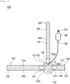
- the hemostatic device 100 generally includes: an inflatable member 110 that compresses the first puncture site p1 formed on the right hand H1 of the patient; a fixing member 120 that can fix the inflatable member 110 to the right hand H1 of the patient; an injection member 180 including a connector portion 181 that can inject a fluid for inflating the inflatable member 110, and a tube portion 183 that connects the connector portion 181 to an inner cavity 113 of the inflatable member 110; and a tube fixing portion 300 that is located on the fixing member 120 and is configured to be capable of fixing the tube portion 183.
- the inflatable member 110 can be implemented by a single balloon having the inner cavity 113 partitioned by a film member.
- the inflatable member 110 can be formed by, for example, joining edge portions of two sheet-shaped film members formed in a substantially rectangular shape in a state in which the inner cavity 113 is defined between the two sheet-shaped film members. Note that the inflatable member 110 may be formed of, for example, a single film-shaped member formed in a bag shape so as to have an inner cavity.
- the inflatable member 110 is inflated when a fluid such as air is supplied to the inner cavity 113, and is contracted when the fluid supplied to the inner cavity 113 is discharged. Note that FIGS. 6 and 7 show cross-sectional views when the fluid is supplied to the inflatable member 110 and the inflatable member 110 is inflated.
- the film member forming the inflatable member 110 can be made of, for example, a resin material having a predetermined thickness.
- the tube portion 183 (see FIGS. 1 and 2 ) to be described later is connected to the inner cavity 113 of the inflatable member 110.
- a material of the film member forming the inflatable member 110 is not particularly limited, and examples thereof include polyolefins such as polyvinyl chloride, polyethylene, polypropylene, polybutadiene, and ethylene-vinyl acetate copolymer (EVA), polyesters such as polyethylene terephthalate (PET) and polybutylene terephthalate (PBT), various thermoplastic elastomers such as polyvinylidene chloride, silicone, polyurethane, polyamide elastomer, polyurethane elastomer, and polyester elastomer, nylon, nylon elastomer, and any combination thereof (blend resin, polymer alloy, laminate, and the like).
- polyolefins such as polyvinyl chloride, polyethylene, polypropylene, polybutadiene, and ethylene-vinyl acetate copolymer (EVA)
- PET polyethylene terephthalate
- PBT polybutylene terephthalate
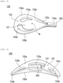
- the inflatable member 110 is disposed on an inner surface 130a side of a support member 130 provided on the fixing member 120.
- An inner surface 130a of the support member 130 is a surface disposed on a body surface side of the hand H of the patient when the hemostatic device 100 is attached to the hand H of the patient.
- An outer surface 130b of the support member 130 is a surface opposite to the inner surface 130a.
- the inflatable member 110 can be directly connected to the inner surface 130a of the support member 130.
- the inflatable member 110 and the support member 130 can be connected by, for example, fusion bonding or adhesion.
- the inflatable member 110 may be connected to the inner surface 130a of the support member 130 via another member.
- the inflatable member 110 may be formed of a single film-shaped member defining an inner cavity between the inflatable member 110 and the inner surface 130a of the support member 130.
- the inflatable member 110 may be configured such that one film-shaped member is directly connected to the inner surface 130a of the support member 130, and an inner cavity is defined between the inner surface 130a of the support member 130 and the one film-shaped member.
- the inflatable member 110 has a circular shape in a plan view shown in FIGS. 1 to 5 .
- a shape of the inflatable member 110 in the plan view is not limited to the circular shape.
- Cross-sectional shapes of the inflatable member 110 before and after inflation, a specific structure of the inflatable member 110, and the like are not particularly limited.
- a marker 115 that aligns the inflatable member 110 with the first puncture site p1 is disposed on the inflatable member 110.
- the marker 115 is disposed on an outer surface of a surface of the inflatable member 110 that is opposite to a surface on which the support member 130 is disposed (a surface disposed on the body surface side of the hand H of the patient when the hemostatic device 100 is attached to the hand H of the patient).
- a specific arrangement position of the marker 115 is not particularly limited as long as the marker 115 is disposed on the inflatable member 110.
- the marker 115 may be disposed on an inner surface of the surface of the inflatable member 110 that is opposite to the surface on which the support member 130 is disposed (the surface disposed on the body surface side of the hand H of the patient when the hemostatic device 100 is attached to the hand H of the patient).
- the marker 115 is disposed at a substantially central position of the inflatable member 110 in a plane direction.
- the marker 115 overlaps a substantially central position of the support member 130 in a plane direction.
- the plane direction of the inflatable member 110 and the plane direction of the support member 130 refer to a direction in which the support member 130 (inflatable member 110) extends in the plan view shown in FIG. 5 .
- the marker 115 can be formed of, for example, a rectangular marker in which the entire marker 115 is colored. Note that the shape, the size, the color, the formation method, the position, and the like of the marker 115 are not particularly limited. For example, the marker 115 may be provided on the support member 130.
- the fixing member 120 includes the support member 130, and a plurality of band bodies 140, 150, and 160 that are connectable to the support member 130 and are to be wrapped around the hand H of the patient.
- the support member 130 includes a first region 131 where the inflatable member 110 is disposed, and a second region 132 that is located outside the first region 131 and is connectable to the first band body 140, the second band body 150, and the third band body 160.
- the support member 130 has a circular shape in the plan view shown in FIG. 5 .
- the first region 131 is a region where the inflatable member 110 overlaps in the plan view shown in FIG. 5 .
- the second region 132 is a region located outside the first region 131 in the plan view shown in FIG. 5 .
- first region 131 can be defined as desired based on the outer shape and size of the inflatable member 110 disposed on the support member 130.
- the second region 132 can be defined based on a relative positional relationship with the first region 131. Therefore, the first region 131 and the second region 132 can be appropriately changed according to the outer shape and size of the inflatable member 110 disposed on the support member 130.
- a center point R which is a center when the first band body 140 and the second band body 150 slide along second holes 133b and 133c, is located in the first region 131.
- the center point R is located at the substantially central position of the support member 130 in the plane direction. Therefore, as shown in FIGS. 6 and 7 , the center point R is located at a position overlapping the marker 115 when projected onto the inflatable member 110.
- the second region 132 has a first hole 133a and the pair of second holes 133b and 133c facing each other with the inflatable member 110 interposed therebetween.
- the first hole 133a is disposed on the distal side (fingertip side) of the hand H with respect to the inflatable member 110.
- the second hole 133b and the second hole 133c are formed with the inflatable member 110 interposed therebetween in a direction intersecting a straight line connecting the first hole 133a and the inflatable member 110 (a straight line connecting the first hole 133a and the tube fixing portion 300.
- the straight line is shown as a virtual line C in FIG. 5 ).
- the holes 133a, 133b, and 133c are formed on a virtual circle along an outer shape of the support member 130.
- the first band body 140 is connected to the second hole 133b.
- the second band body 150 is connected to the second hole 133c.
- the third band body 160 is connected to the first hole 133a.
- a width of one end portion 141 of the first band body 140 is smaller than a hole length of the second hole 133b. Therefore, as shown in FIG. 8 , the first band body 140 is slidable around the inflatable member 110 in the second region 132 about the center point A of the support member 130 in a state in which the one end portion 141 of the first band body 140 is connected to the second hole 133b.
- a width of one end portion 151 of the second band body 150 is smaller than a hole length of the second hole 133c. Therefore, as shown in FIG. 8 , the second band body 150 is slidable around the inflatable member 110 in the second region 132 about the center point R in a state in which the one end portion 151 of the second band body 150 is connected to the second hole 133c.
- An angle (slidable range) at which the first band body 140 and the second band body 150 are slidable around the inflatable member 110 about the center point R is not particularly limited, and may be set to, for example, 1° to 75°.
- a width of one end portion 161 of the third band body 160 is substantially the same as a hole length of the first hole 133a. Therefore, the third band body 160 is restricted from sliding about the center point R in a state in which the one end portion 161 of the third band body 160 is connected to the first hole 133a.
- first curved regions 134a each curved in a convex shape away from the inflatable member 110 (an upper side in FIGS. 6 and 7 ) are formed in portions where the first hole 133a and the tube fixing portion 300 are disposed in the second region 132 of the support member 130.
- second curved regions 134b each curved in a convex shape toward the inflatable member 110 (a lower side in FIGS. 6 and 7 ) are formed in portions where the second holes 133b and 133c are formed in the second region 132 of the support member 130.
- the support member 130 is made of a more rigid material than the band bodies 140, 150, and 160.
- constituent material of the support member 130 having the rigidity as described above examples include acrylic resin, polyvinyl chloride (in particular, rigid polyvinyl chloride), polyolefin such as polyethylene, polypropylene, and polybutadiene, polystyrene, poly-(4-methylpentene-1), polycarbonate, ABS resin, polymethyl methacrylate (PMMA), polyacetal, polyacrylate, polyacrylonitrile, polyvinylidene fluoride, ionomer, acrylonitrile-butadiene-styrene copolymer, and polyethylene terephthalate (PET).
- acrylic resin polyvinyl chloride (in particular, rigid polyvinyl chloride), polyolefin such as polyethylene, polypropylene, and polybutadiene
- polystyrene poly-(4-methylpentene-1)
- polycarbonate ABS resin
- PMMA polymethyl methacrylate
- PET polyethylene terephthalate
- each of the inflatable member 110 and the support member 130 portions overlapping each other in the plan view shown in FIGS. 3 and 4 can be transparent.
- the inflatable member 110 and the support member 130 are configured as described above, as shown in FIGS. 12 , 13 , and 14 , when the hemostatic device 100 is attached to the right hand H1 of the patient, an operator can more easily visually check positions of the marker 115 and/or the first puncture site p1 via the inflatable member 110 and the support member 130.
- transparent includes colored transparent, colorless transparent, and translucent.
- the first band body 140 includes the one end portion 141 that is connectable to the second hole 133b of the support member 130, the other end portion 143 that is free and not connected to the support member 130, and a body portion 145 that extends between the one end portion 141 and the other end portion 143.
- the second band body 150 includes the one end portion 151 that is connectable to the second hole 133c of the support member 130, the other end portion 153 that is free and not connected to the support member 130, and a body portion 155 that extends between the one end portion 151 and the other end portion 153.
- the first band body 140 extends from the support member 130 in a predetermined first direction.
- the second band body 150 extends from the support member 130 in a predetermined second direction different from the first direction.
- the first band body 140 and the second band body 150 can be wrapped around an outer periphery of the right hand H1.
- the third band body 160 includes the one end portion 161 that is connectable to the first hole 133a of the support member 130, the other end portion 163 that is free and not connected to the support member 130, and a body portion 165 that extends between the one end portion 161 and the other end portion 163.
- the third band body 160 extends from the support member 130 in a third direction different from the first direction in which the first band body 140 extends and the second direction in which the second band body 150 extends.
- the third band body 160 can be hooked on an inter-finger portion fb located between the thumb and the forefinger of the right hand H1 of the patient in a state in which the inflatable member 110 is disposed at the first puncture site p1.
- the one end portions 141, 151, and 161 of the band bodies 140, 150, and 160 can be inserted into and rolled around the holes 133a, 133b, and 133c of the support member 130, respectively.
- a structure for connecting the one end portions 141, 151, and 161 of the band bodies 140, 150, and 160 to the support member 130 is not particularly limited.
- a member for example, a hook-and-loop fastener capable of holding and releasing a state of being rolled around each of the holes 133a, 133b, and 133c of the support member 130 can be disposed at respective one end portions 141.
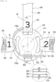
- the one end portions 141, 151, and 161 of the band bodies 140, 150, and 160 are provided with symbols M (including figures and characters) for being capable of identifying the band bodies 140, 150, and 160.
- the one end portion 141 of the first band body 140, the one end portion 151 of the second band body 150, and the one end portion 161 of the third band body 160 are respectively provided with numbers "1", "2", and "3".
- the numbers provided on the band bodies 140, 150, and 160 correspond to an order of rolling the band bodies 140, 150, and 160 when the operator attaches the hemostatic device 100 to the right hand H1 of the patient.
- the operator can attach the band bodies 140, 150, and 160 to the right hand H1 of the patient in a correct order by visually recognizing the symbols M.
- the size, the color, the formation method, the position, and the like of the symbol M are not particularly limited.
- a constituent material of each of the band bodies 140, 150, and 160 is not particularly limited, and may be, for example, vinyl chloride resin, amide resin, amide elastomer resin, polyurethane resin, or polyester resin.
- the shape, the length, the thickness, and the like of each of the band bodies 140, 150, and 160 are not particularly limited.
- the hemostatic device 100 includes five fixing sites, namely a first fixing site 171, a second fixing site 172, a third fixing site 173, a fourth fixing site 174, and a fifth fixing site 175.
- the first fixing site 171 is disposed on an outer surface of the first band body 140.
- the second fixing site 172 is disposed on an outer surface of the second band body 150.
- the third fixing site 173 is disposed on an inner surface of the first band body 140.
- the fourth fixing site 174 is disposed on an inner surface of the second band body 150.
- the fifth fixing site 175 is disposed on an inner surface of the third band body 160.
- each of the band bodies 140, 150, and 160 is a surface disposed on a body surface side of the patient when the hemostatic device 100 is attached to the patient, and the “outer surface” of each of the band bodies 140, 150, and 160 is a surface located on a side opposite to the inner surface.
- the first fixing site 171 and the second fixing site 172 are each formed of a male side of the hook-and-loop fastener.
- the third fixing site 173, the fourth fixing site 174, and the fifth fixing site 175 are each formed of a female side of the hook-and-loop fastener.
- the hook-and-loop fastener in this specification is a fastener that can be attached to and detached from a surface, such as Magic Tape (registered trademark) and Velcro (registered trademark).
- the fixing sites 171, 172, 174, and 175 are used to connect the band bodies 140, 150, and 160 to one another in a state in which the hemostatic device 100 is attached to the right hand H1 of the patient.
- the one end portions 141, 151, and 161 corresponding to the fixing sites 173, 174, and 175 are used to connect the band bodies 140, 150, and 160 to the support member 130.
- specific structures of the fixing sites 171, 172, 174, and 175 are not limited as long as the support member 130 can be fixed to the right hand H1 of the patient.
- arrangement of a part of the fixing sites can be omitted and positions of the fixing sites in the band bodies 140, 150, and 160 can be changed as desired.
- each of the fixing sites 171, 172, 173, 174, and 175 When each of the fixing sites 171, 172, 173, 174, and 175 is formed of the hook-and-loop fastener, a configuration may be such that the male and female sides of the hook-and-loop fastener are interchanged.
- Each of the fixing sites 171, 172, 173, 174, and 175 may be formed of, for example, a snap, a button, a clip, a coupling mechanism including a frame portion having a hole and an engaged portion including a protrusion engageable with the frame portion, or the like.
- the injection member 180 includes the connector portion 181 that can inject a fluid for inflating the inflatable member 110, and the tube portion 183 that connects the connector portion 181 to the inner cavity 113 of the inflatable member 110.
- the connector portion 181 has a built-in check valve (not shown).
- a syringe (not shown) can be connected to the connector portion 181.
- a cushioning member 182 having an inflatable space is disposed between the connector portion 181 and the inflatable member 110.
- the cushioning member 182 is formed of a flexible bag-shaped member having a space defined therein. Note that the cushioning member 182 may be provided with an arrow-shaped marker indicating an insertion direction of the syringe into the connector portion 181.
- the connector portion 181 is connected to one end side of the cushioning member 182. An inner cavity of the connector portion 181 communicates with the space of the cushioning member 182. However, while the check valve built in the connector portion 181 is closed, communication between the inner cavity of the connector portion 181 and the space of the cushioning member 182 is blocked.
- the flexible tube portion 183 is connected to the other end side of the cushioning member 182.
- An inner cavity of the tube portion 183 communicates with the space of the cushioning member 182.
- the tube portion 183 is connected to the inflatable member 110 at the other end portion opposite to one end portion connected to the cushioning member 182.
- the inner cavity of the tube portion 183 communicates with the inner cavity 113 of the inflatable member 110.
- the operator When inflating the inflatable member 110, the operator inserts a front tube portion of the syringe (not shown) into the connector portion 181 to open the check valve.
- the operator injects air in the syringe into the inner cavity 113 of the inflatable member 110 by pushing a plunger of the syringe in a state in which the check valve of the connector portion 181 is opened.
- the inflatable member 110 When the air is injected into the inner cavity 113 of the inflatable member 110, the inflatable member 110 is inflated. When the inflatable member 110 is inflated, the cushioning member 182 communicating with the inner cavity 113 of the inflatable member 110 via the tube portion 183 is inflated. The operator can easily recognize that the inflatable member 110 is inflated without air leakage by visually checking inflation of the cushioning member 182.
- the operator When contracting the inflatable member 110, the operator inserts the front tube portion of the syringe into the connector portion 181 and pulls the plunger of the syringe. The operator can discharge the air in the inner cavity 113 of the inflatable member 110 to the syringe by performing the above-described operation.
- the connector portion 181, the cushioning member 182, and the tube portion 183 may be prepared and provided in a state of being connected to the inflatable member 110, or in a state of being separated from the inflatable member 110.
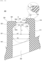
- the tube fixing portion 300 includes a first member 310, a second member 320 that is located closer to the inflatable member 110 than is the first member 310 and faces the first member 310, a slit portion 330 that is formed between the first member 310 and the second member 320 and allows insertion of the tube portion 183, and a tube holding portion 340 that is surrounded by the first member 310, the second member 320, and the slit portion 330 and holds the tube portion 183.
- the first member 310 includes a first body portion 311, a first curved portion 312 that is curved toward the second member 320, and a first distal-end surface 313 that is located at a distal end of the first curved portion 312.
- the second member 320 includes a second body portion 321, a second curved portion 322 that is curved toward the first member 310, and a second distal-end surface 323 that is located at a distal end of the second curved portion 322 and faces the first distal-end surface 313 across the slit portion 330.
- a width Z1 of the first body portion 311 (here, the "width" is a length in a left-right direction in FIG. 5 ) is set to be the same value as a width Z2 of the first distal-end surface 313, and a width Z3 of the second body portion 321 is set to be the same value as a width Z4 of the second distal-end surface 323.
- width Z1 of the first body portion 311, the width Z2 of the first distal-end surface 313, the width Z3 of the second body portion 321, and the width Z4 of the second distal-end surface 323 are a length of the tube fixing portion 300 in a left-right direction in FIG. 1 .
- a width Y1 of the slit portion 330 formed between the first curved portion 312 and the second curved portion 322 (here, the "width" is a length in a left-right direction in FIG. 10 ) is smaller than a width Y2 of the tube holding portion 340 and smaller than a diameter ⁇ 1 of the tube portion 183. Therefore, the hemostatic device 100 can prevent the tube portion 183 inserted into the tube holding portion 340 from being unintentionally removed from the tube fixing portion 300.
- the width Y2 of the tube holding portion 340 is preferably equal to the diameter ⁇ 1 of the tube portion 183. With this configuration, the hemostatic device 100 can prevent the tube portion 183 from moving in the left-right direction in FIG.
- a height of the tube holding portion 340 (here, the "height" is a length in an upper-lower direction in FIG. 10 ) is preferably equal to the diameter ⁇ 1 of the tube portion 183.
- the hemostatic device 100 can prevent the tube portion 183 from moving in the upper-lower direction in FIG. 10 in the tube holding portion 340. Therefore, the hemostatic device 100 can prevent the tube portion 183 inserted into the tube holding portion 340 from being unintentionally removed from the tube fixing portion 300.
- the width Y1 of the slit portion 330 and the width Y2 of the tube holding portion 340 are a length of the tube fixing portion 300 in an upper-lower direction in FIG. 1 .
- a part of the first member 310 (a part of the first curved portion 312) is further away from the inflatable member 110 than is the second member 320 in a direction perpendicular to a virtual plane S defined by the slit portion 330, and the first distal-end surface 313 includes a first region 313a that does not face the second distal-end surface 323 across the slit portion 330, and a second region 313b that corresponds to the second distal-end surface 323 across the slit portion 330.
- the virtual plane S defined by the slit portion 330 here refers to a plane that passes through an upper end surface 324 of the second member 320 and extends toward the first member 310.
- the virtual plane S is a plane that passes through the upper end surface 324 of the second member 320 and extends perpendicularly toward the first member 310.
- the hemostatic device 100 has a height difference between the first member 310 and the second member 320 with reference to the virtual plane S.
- An upper end surface 314 of the first member 310 is higher than the upper end surface 324 of the second member 320 (away from the inflatable member 110).
- the hemostatic device 100 is configured such that a region where the first distal-end surface 313 and the second distal-end surface 323 face each other across the slit portion 330 in a height direction of the tube fixing portion 300 (the upper-lower direction in FIG. 10 ) (a region where the first distal-end surface 313 and the second distal-end surface 323 overlap each other in a direction orthogonal to the upper-lower direction in FIG. 10 ) is reduced.
- the hemostatic device 100 when the operator pushes the tube portion 183 into the tube fixing portion 300 (inserts the tube portion 183 into the tube fixing portion 300), the first member 310 can be deformed in a direction in which the slit portion 330 is widened by an external force applied to the tube portion 183, and then the second member 320 can be deformed in the direction in which the slit portion 330 is widened in a state of maintaining deformation of the first member 310. Accordingly, the hemostatic device 100 can reduce a force required for the operator to insert the tube portion 183 into the tube fixing portion 300 in a state of being attached to the right hand H1 of the patient, and the operator can easily insert the tube portion 183 into the tube fixing portion 300.
- a hole 350 is formed between the first member 310 and the second member 320 as shown in FIGS. 4 , 5 , and 10 .
- the hole 350 is a through hole located between the first member 310 and the second member 320 and penetrating the support member 130 between the inner surface 130a and the outer surface 130b of the support member 130.
- a position of the hole 350 is not particularly limited as long as the position is between the first member 310 and the second member 320 in the plan view shown in FIG. 5 .
- the support member 130 has the hole 350 between the first member 310 and the second member 320. Accordingly, in the hemostatic device 100, when an external force (a force pressing the tube portion 183 in the left-right direction in FIG. 5 , for example, a force pressing the tube portion 183 from a left side to a right side in FIG. 5 or a force pressing the tube portion 183 from the right side to the left side in FIG.
- an external force a force pressing the tube portion 183 in the left-right direction in FIG. 5 , for example, a force pressing the tube portion 183 from a left side to a right side in FIG. 5 or a force pressing the tube portion 183 from the right side to the left side in FIG.
- the hemostatic device 100 when the external force (the force pressing the tube portion 183 from the left side to the right side in FIG. 5 ) is applied to the tube portion 183 in a state in which the tube portion 183 is inserted into the tube holding portion 340, a part of the tube portion 183 enters the hole 350, whereby the tube portion 183 can be prevented from moving from the left side to the right side in FIG. 5 , and the connector portion 181 and the cushioning member 182 can be prevented from sliding in a direction away from the tube fixing portion 300. Therefore, in the hemostatic device 100, when the external force (the force pressing the tube portion 183 from the left side to the right side in FIG.
- the hole 350 functions as a hole for removing a mold when molding the first member 310 and the second member 320. Therefore, in the hemostatic device 100, the number of molds when molding the support member 130 that is integrally formed with the tube fixing portion 300 can be reduced, and a manufacturing cost can be reduced.
- a vertical width of the hole 350 (here, the "vertical width” is a length in an upper-lower direction in FIG. 5 and a length in the left-right direction in FIG. 10 ) can be the width Y2 of the tube holding portion 340, for example.
- the vertical width of the hole 350 is preferably equal to or greater than the diameter ⁇ 1 of the tube portion 183. Accordingly, in the hemostatic device 100, when the external force (the force pressing the tube portion 183 in the left-right direction in FIG. 5 ) is applied to the tube portion 183 in a state in which the tube portion 183 is inserted into the tube holding portion 340, a part of the tube portion 183 can easily enter the hole 350.
- a lateral width of the hole 350 (here, the "lateral width” is a length in the left-right direction in FIG. 5 ) can be the width Z1 of the first body portion 311 or the width Z3 of the second body portion 321, for example.
- the first curved portion 312 has a first curved surface 312a that is curved toward the second member 320.
- the first curved surface 312a is formed at a position facing the second distal-end surface 323 across the tube holding portion 340. Therefore, in the hemostatic device 100, when the operator separates the tube portion 183 from the tube fixing portion 300 (removes the tube portion 183 from the tube fixing portion 300), the tube portion 183 is moved from the tube holding portion 340 toward the slit portion 330 with the first curved surface 312a as a guide surface.
- the hemostatic device 100 can reduce a force required for the operator to remove the tube portion 183 from the tube fixing portion 300 in a state of being attached to the right hand H1 of the patient, and the operator can easily remove the tube portion 183 from the tube fixing portion 300.
- the second curved portion 322 has a second curved surface 322a that is curved toward the first member 310.
- the tube portion 183 fixed to the tube fixing portion 300 is moved along the first curved surface 312a and/or the second curved surface 322a, whereby the tube portion 183 can be more easily directed to the slit portion 330. Accordingly, it is easier for the operator to remove the tube portion 183 from the tube fixing portion 300.
- a thickness of a distal portion of each of the first curved portion 312 and the second curved portion 322 (that is, a length X1 of the first distal-end surface 313 obtained by adding a length X2 of the first region 313a and a length X3 of the second region 313b of the first distal-end surface 313, or a length of the second distal-end surface 323.
- the "length” is a length in the upper-lower direction in the enlarged view of the first distal-end surface 313 in FIG.
- the tube fixing portion 300 is not particularly limited, and can be set to any thickness with little risk of breakage when the tube fixing portion 300 is formed stably and the operator attaches the tube portion 183 to and detaches the tube portion 183 from the tube fixing portion 300.
- the tube fixing portion 300 is configured such that the region where the first distal-end surface 313 and the second distal-end surface 323 face each other across the slit portion 330 in the height direction of the tube fixing portion 300 (the upper-lower direction in FIG. 10 ) is reduced.
- the tube fixing portion 300 can be designed such that distal portions of the first curved portion 312 and the second curved portion 322 have large thicknesses while reducing a force required for the operator to attach the tube portion 183 to and detach the tube portion 183 from the tube fixing portion 300.
- the length X3 of the second region 313b of the first distal-end surface 313 is preferably smaller than a radius r1 of the tube portion 183.
- the second distal-end surface 323 includes a curved surface portion 323c at a position corresponding to the first distal-end surface 313 across the slit portion 330. Since the curved surface portion 323c is formed between the upper end surface 324 and the second distal-end surface 323 of the second member 320 adjacent to the slit portion 330, the hemostatic device 100 guides a moving direction of the tube portion 183 to the curved surface portion 323c when inserting the tube portion 183 into the tube fixing portion 300, and facilitates the tube portion 183 held by the tube holding portion 340 to be directed to the slit portion 330. Therefore, the hemostatic device 100 can reduce the force required for the operator to insert the tube portion 183 into the tube fixing portion 300 in a state of being attached to the right hand H1 of the patient, and the operator can easily insert the tube portion 183 into the tube fixing portion 300.
- the hemostatic device 100 can reduce a force required for the operator to attach the tube portion 183 to and detach the tube portion 183 from the tube fixing portion 300 in a state of being attached to the right hand H1 of the patient. Therefore, in the hemostatic device 100, it is possible to prevent an external force from being unintentionally applied to the first puncture site p1, and/or to prevent the hemostatic device 100 from shifting due to unintentional application of an external force to the inflatable member 110.
- the tube fixing portion 300 is made of a material more rigid than a material forming the tube portion 183. As shown in FIG. 3 , the tube fixing portion 300 is located on the outer surface 130b of the support member 130 made of a more rigid material than the band bodies 140, 150, and 160. Therefore, the operator can easily perform an operation of attaching the tube portion 183 to and detaching the tube portion 183 from the tube fixing portion 300 in a state in which the hemostatic device 100 is attached to the right hand H1 of the patient.
- the tube fixing portion 300 is made of a more rigid material than the tube portion 183, the first body portion 311 and the second member 320 are less likely to be deformed by an unintentionally applied force, and the tube portion 183 held by the tube fixing portion 300 can be prevented from being unintentionally removed from the tube fixing portion 300. Since the tube fixing portion 300 is provided on the support member 130 made of the rigid material, the hemostatic device 100 can be prevented from shifting due to unintentional application of the external force to the inflatable member 110 connected to the support member 130. Note that as shown in FIG.
- the hemostatic device 100 when the tube fixing portion 300 is located on the outer surface 130b of the support member 130 outside the inflatable member 110, the hemostatic device 100 can be more reliably prevented from shifting due to unintentional application of the external force to the inflatable member 110 connected to the support member 130.
- a method for forming the tube fixing portion 300 is not particularly limited, and as shown in FIG. 3 , the tube fixing portion 300 can be formed integrally with the support member 130, and can be made of the same constituent material as the support member 130.
- a position of the tube fixing portion 300 is not limited as long as the tube fixing portion 300 is provided at a position where the tube portion 183 is easily attached to and detached from the tube fixing portion 300 in a state in which the hemostatic device 100 is attached to the right hand H1 of the patient. Therefore, the tube fixing portion 300 may be provided on the fixing member 120 for fixing the inflatable member 110, and may be provided on any one of the band bodies 140, 150, and 160.
- the tube fixing portion 300 is located in the first curved region 134a of the support member 130 and outside the inflatable member 110.
- the hemostatic device 100 is attached such that the first curved region 134a of the support member 130 does not come into close contact with a body surface of the right hand H1 of the patient. Therefore, the operator can hold the support member 130 of the hemostatic device 100 attached to the right hand H1 of the patient by pinching with two fingers when fixing the tube portion 183 to the tube fixing portion 300.
- the operator can insert the tube portion 183 into the tube fixing portion 300 with one finger located on an outer surface 130b side of the support member 130, and absorb an external force applied to the tube portion 183 with the other finger located on an inner surface 130a side of the support member 130.
- the operator can fix the tube portion 183 to the tube fixing portion 300 without applying an unintended external force to the support member 130. Since the operator pinches and holds the support member 130 of the hemostatic device 100 attached to the right hand H1 of the patient when fixing the tube portion 183 to the tube fixing portion 300, the support member 130 can be more reliably prevented from being inclined due to the external force applied to the tube portion 183.
- the inflatable member 100 when the operator inserts the tube portion 183 into the tube fixing portion 300 in a state in which the hemostatic device 100 is attached to the right hand H1 of the patient, it is possible to prevent an external force from being unintentionally applied to the first puncture site p1, and/or to prevent the hemostatic device 100 from shifting due to unintentional application of an external force to the inflatable member 110 caused by transmission of the external force to the support member 130.
- the tube fixing portion 300 is provided at a position facing the third band body 160 with the inflatable member 110 interposed therebetween.
- the connection portion K between the inflatable member 110 and the tube portion 183 is disposed on a third band body 160 side in view of convenience in operating the injection member 180 when the operator adjusts a fluid amount of the inflatable member 110. Therefore, since the tube fixing portion 300 is provided at the position facing the third band body 160, it is possible to reduce a remainder of the tube portion 183 that may be generated between the tube fixing portion 300 and the connection portion K of the tube portion 183 fixed to the tube fixing portion 300.
- an end portion of the tube portion 183 on a connector portion 181 side can be prevented from swinging, and an external force can be prevented from being unintentionally applied to the inflatable member 110.
- a radius of curvature formed by the tube portion 183 located between the connection portion K and the tube fixing portion 300 is increased, and thus the tube portion 183 can also be prevented from kinking.
- FIG. 12 shows a state in which the sheath tube of the introducer 200 is inserted into the first puncture site p1 and various procedures have been performed.
- the operator When attaching the hemostatic device 100 to the right hand H1 of the patient, the operator disposes the support member 130 to overlap a dorsal side of the right hand H1 of the patient as shown in FIG. 12 . At this time, the operator can appropriately position the inflatable member 110 at the first puncture site p1 by disposing the marker 115 at the first puncture site p1 while visually checking a position of the marker 115 disposed on the inflatable member 110.
- the operator may pull out a part of the sheath tube of the introducer 200 from the first puncture site p1 formed in the right hand H1 of the patient after finishing a procedure using the introducer 200 and before attaching the hemostatic device 100 to the right hand H1 of the patient.
- the operator can start an attachment operation of the hemostatic device 100 after pulling out the sheath tube by approximately 2 cm to 3 cm to a hand side of the operator in a state in which the sheath tube of the introducer 200 is indwelled in the blood vessel B.
- the operator wraps the first band body 140 and the second band body 150 along the outer periphery of the right hand H1 of the patient.
- the operator can connect the first band body 140 and the second band body 150 via the fixing sites 171 and 174 by bringing the fourth fixing site 174 disposed on the inner surface of the second band body 150 (see FIG. 2 ) into contact with the first fixing site 171 disposed on the outer surface of the first band body 140 (see FIG. 1 ).
- the operator passes the third band body 160 through the inter-finger portion fb located between the thumb and the forefinger of the right hand H1 of the patient, and disposes a part of the third band body 160 on a palm side of the right hand H1 of the patient.
- the operator can connect the second band body 150 and the third band body 160 via the fixing sites 172 and 175 by bringing the fifth fixing site 175 disposed on the inner surface of the third band body 160 (see FIG. 2 ) into contact with the second fixing site 172 disposed on the outer surface of the second band body 150 (see FIG. 1 ).
- the operator inflates the inflatable member 110 by injecting air into the inflatable member 110 in a state in which the syringe is connected to the connector portion 181.
- the inflatable member 110 when the inflatable member 110 is inflated, the inflatable member 110 applies a compressive force to the first puncture site p1 of the right hand H1 of the patient.
- the operator fixes the tube portion 183 to the tube fixing portion 300 (see FIGS. 3 to 5 ).
- the tube fixing portion 300 can reduce a force required for the operator to fix the tube portion 183 to the tube fixing portion 300.
- the operator pinches and holds the support member 130 of the hemostatic device 100 attached to the right hand H1 of the patient when fixing the tube portion 183 to the tube fixing portion 300, whereby the support member 130 can be prevented from being inclined due to an external force applied to the tube portion 183 by the operator. Therefore, in the hemostatic device 100, it is possible to prevent an external force from being unintentionally applied to the first puncture site p1, and/or to prevent the hemostatic device 100 from shifting due to unintentional application of an external force to the inflatable member 110.
- the operator can stop bleeding at the first puncture site p1 formed in the right hand H1 of the patient using the hemostatic device 100.
- the operator slides the band bodies 140 and 150 about the center point R when wrapping the band bodies 140 and 150 around the right hand H1 of the patient.
- the operator can stop bleeding at the second puncture site p2 formed in the right hand H1 of the patient by wrapping the slid band bodies 140 and 150 around the right hand H1 of the patient at a position closer to the forearm A (proximal side) than is the first puncture site p1.
- the hemostatic device 100 includes: the inflatable member 110 configured to be capable of compressing a site where bleeding is to be stopped in a limb of a patient; the fixing member 120 configured to be capable of fixing the inflatable member 110 to the limb of the patient; the injection member 180 including the connector portion 181 configured to be capable of injecting a fluid for inflating the inflatable member 110 and the tube portion 183 connecting the connector portion 181 to the inner cavity 113 of the inflatable member 110; and the tube fixing portion 300 located on the fixing member 120 and configured to be capable of fixing the tube portion 183.
- the tube fixing portion 300 includes the first member 310, the second member 320 located closer to the inflatable member 110 than is the first member 310 and facing the first member 310, the slit portion 330 formed between the first member 310 and the second member 320 and configured to allow insertion of the tube portion 183, and the tube holding portion 340 surrounded by the first member 310, the second member 320, and the slit portion 330 and configured to hold the tube portion 183.
- the first member 310 includes the first body portion 311, the first curved portion 312 curved toward the second member 320, and the first distal-end surface 313 located at a distal end of the first curved portion 312.
- the second member 320 includes the second body portion 321, the second curved portion 322 curved toward the first member 310, and the second distal-end surface 323 located at a distal end of the second curved portion 322 and facing the first distal-end surface 313 across the slit portion 330.
- a part of the first member 310 is further away from the inflatable member 110 than is the second member 320 in a direction perpendicular to the virtual plane S defined by the slit portion 330.
- the first distal-end surface 313 includes the first region 313a not facing the second distal-end surface 323 across the slit portion 330 and the second region 313b corresponding to the second distal-end surface 323 across the slit portion 330.
- the first curved portion 312 includes the first curved surface 312a curved toward the second member 320.
- the first curved surface 312a faces the second distal-end surface 323 across the tube holding portion 340.
- the hemostatic device 100 configured as described above, by providing a height difference between the first member 310 and the second member 320, a region where the first distal-end surface 313 and the second distal-end surface 323 face each other across the slit portion 330 is reduced. Therefore, the hemostatic device 100 can reduce a force required for the operator to insert the tube portion 183 into the tube fixing portion 300 in a state of being attached to the right hand H1 of the patient.
- the first curved surface 312a is formed at a position facing the second distal-end surface 323 across the tube holding portion 340.
- the hemostatic device 100 when the operator separates the tube portion 183 from the tube fixing portion 300 (removes the tube portion 183 from the tube fixing portion 300), the tube portion 183 can be moved from the tube holding portion 340 toward the slit portion 330 with the first curved surface 312a as a guide surface. Accordingly, the hemostatic device 100 can reduce a force required for the operator to remove the tube portion 183 from the tube fixing portion 300 in the state of being attached to the right hand H1 of the patient. Therefore, in the hemostatic device 100, it is possible to prevent an external force from being unintentionally applied to the puncture sites p1 and p2, and/or to prevent the hemostatic device 100 from shifting due to unintentional application of an external force to the inflatable member 110.
- the fixing member 120 includes the support member 130 to which the inflatable member 110 is fixed, and a band body (band bodies 140, 150, and 160) that is connectable to the support member 130, the support member 130 is made of a material more rigid than a material forming the band body, and the tube fixing portion 300 is made of a material more rigid than a material forming the tube portion 183, and is located on a surface (outer surface 130b) of the support member 130.
- a band body band bodies 140, 150, and 160
- the operator can easily perform an operation of attaching the tube portion 183 to and detaching the tube portion 183 from the tube fixing portion 300 in a state in which the hemostatic device 100 is attached to the right hand H1 of the patient.
- the tube fixing portion 300 is made of a more rigid material than the tube portion 183, the first body portion 311 and the second member 320 are less likely to be deformed by an unintentionally applied force, and the tube portion 183 held by the tube fixing portion 300 can be prevented from being unintentionally removed from the tube f i xing portion 300.
- the tube fixing portion 300 is provided on the support member 130 made of a rigid material, the hemostatic device 100 can be prevented from shifting due to unintentional application of the external force to the inflatable member 110 connected to the support member 130.
- the support member 130 includes the first curved region 134a curved in a direction away from the inflatable member 110, and the tube fixing portion 300 is located in the first curved region 134a and outside the inflatable member 110.
- the hemostatic device 100 configured as described above is attached such that the first curved region 134a of the support member 130 does not come into close contact with a body surface of the right hand H1 of the patient. Therefore, the operator holds and pinches the support member 130 of the hemostatic device 100 attached to the right hand H1 of the patient when fixing the tube portion 183 to the tube fixing portion 300, whereby an external force applied to the tube portion 183 can be absorbed by fingers of the operator. Accordingly, the operator can fix the tube portion 183 to the tube fixing portion 300 without applying an unintended external force to the support member 130.
- the support member 130 of the hemostatic device 100 attached to the right hand H1 of the patient since the operator holds and pinches the support member 130 of the hemostatic device 100 attached to the right hand H1 of the patient when fixing the tube portion 183 to the tube fixing portion 300, the support member 130 can be more reliably prevented from being inclined due to the external force applied to the tube portion 183 by the operator. Therefore, in the inflatable member 100, when the operator inserts the tube portion 183 into the tube fixing portion 300 in a state in which the hemostatic device 100 is attached to the right hand H1 of the patient, it is possible to prevent an external force from being unintentionally applied to the puncture sites p1 and p2, and/or to prevent the hemostatic device 100 from shifting due to unintentional application of an external force to the inflatable member 110 caused by transmission of the external force to the support member 130.
- the band body includes the first band body 140 extending from the support member 130 in a first direction, the second band body 150 extending from the support member 130 in a second direction different from the first direction, and the third band body 160 configured to be disposed between fingers of the patient and extending from the support member 130 in a third direction different from the first direction and the second direction.
- the connection portion K between the inflatable member 110 and the tube portion 183 is located on a third band body 160 side.
- the tube fixing portion 300 is located on a surface (outer surface 130b) of the support member 130 facing the third band body 160 with the inflatable member 110 interposed therebetween.
- the hemostatic device 100 configured as described above, it is possible to reduce a remainder of the tube portion 183 that may be generated between the tube fixing portion 300 and the connection portion K of the tube portion 183 fixed to the tube fixing portion 300.
- the tube portion 183 can be prevented from kinking between the connection portion K and the tube fixing portion 300.
- the length X3 of the second region 313b of the first distal-end surface 313 is smaller than the radius r1 of the tube portion 183.
- the hemostatic device 100 when the operator inserts the tube portion 183 into the tube fixing portion 300, the hemostatic device 100 can reduce an amount of work required for the operator to move the tube portion 183 from the slit portion 330 toward the tube holding portion 340. Therefore, the hemostatic device 100 can reduce a force with which the operator pushes the tube portion 183 from the slit portion 330 toward the tube holding portion 340, and the operator can more easily insert the tube portion 183 into the tube fixing portion 300. Accordingly, in the hemostatic device 100, it is possible to prevent an external force from being unintentionally applied to the puncture sites p1 and p2, and/or to prevent the hemostatic device 100 from shifting due to unintentional application of an external force to the inflatable member 110.
- the second distal-end surface 323 includes the curved surface portion 323c at a position corresponding to the first distal-end surface 313 across the slit portion 330.
- the hemostatic device 100 guides a moving direction of the tube portion 183 to the curved surface portion 323c when the operator inserts the tube portion 183 into the tube fixing portion 300, and facilitates the tube portion 183 held by the tube holding portion 340 to be directed to the slit portion 330. Therefore, the hemostatic device 100 can reduce a force required for the operator to insert the tube portion 183 into the tube fixing portion 300 in a state of being attached to the right hand H1 of the patient.
- the hemostatic device 100 it is possible to prevent an external force from being unintentionally applied to the puncture sites p1 and p2, and/or to prevent the hemostatic device 100 from shifting due to unintentional application of an external force to the inflatable member 110.
- FIG. 17 is an enlarged view of a part of a hemostatic device 100A according to a modification.
- a tube fixing portion 300A of the hemostatic device 100A according to the modification includes a first member 310A and a second member 320A.
- a width ZA2 of a first distal-end surface 313A is smaller than a width ZA1 of a first body portion
- a width ZA4 of a second distal-end surface 323A is smaller than a width ZA3 of a second body portion.
- the hemostatic device 100A configured as described above, it is possible to reduce widths of the first distal-end surface 313A and the second distal-end surface 323A defining the slit portion 330 while increasing an area for disposing the tube fixing portion 300A to the support member 130. Therefore, the hemostatic device 100A can ensure a strength of the tube fixing portion 300A, and reduce a force required for the operator to attach the tube portion 183 to and detach the tube portion 183 from the tube fixing portion 300A in a state of being attached to the right hand H1 of the patient.
- the hemostatic device 100A it is possible to prevent an external force from being unintentionally applied to the puncture sites p1 and p2, and/or to prevent the hemostatic device 100 from shifting due to unintentional application of an external force to the inflatable member 110.
- the hemostatic device 100A can also increase the strength of the tube fixing portion 300A.
- hemostatic device according to the invention has been described above through the present embodiment, but the invention is not limited to the contents described in the specification, and can be appropriately changed based on the description of the claims.
- the hemostatic device for stopping bleeding at the puncture site formed on the dorsal side of the right hand and the puncture site formed in the forearm has been exemplified in the description of the present embodiment.
- the hemostatic device may stop bleeding at a puncture site formed on a dorsal side of a left hand, a puncture site formed in a palm of any one of left and right hands, a puncture site formed in a foot of the patient (for example, dorsum or sole), or the like.
- each part of the hemostatic device are not particularly limited as long as the inflatable member can be disposed at a site where bleeding is to be stopped, and can be appropriately changed.
Landscapes
- Health & Medical Sciences (AREA)
- Life Sciences & Earth Sciences (AREA)
- Surgery (AREA)
- Heart & Thoracic Surgery (AREA)
- Molecular Biology (AREA)
- Vascular Medicine (AREA)
- Engineering & Computer Science (AREA)
- Biomedical Technology (AREA)
- Reproductive Health (AREA)
- Medical Informatics (AREA)
- Nuclear Medicine, Radiotherapy & Molecular Imaging (AREA)
- Animal Behavior & Ethology (AREA)
- General Health & Medical Sciences (AREA)
- Public Health (AREA)
- Veterinary Medicine (AREA)
- Biophysics (AREA)
- Hematology (AREA)
- Surgical Instruments (AREA)
Abstract
Description
- The present invention relates to a hemostatic device.
- As one of catheter procedures, a procedure is known in which various medical elongated bodies are introduced into a blood vessel through a puncture site formed by puncturing the blood vessel of an arm or hand of a patient, and treatment or cure is performed on a lesion site.
For example,PTL 1 discloses a hemostatic device for stopping bleeding at a puncture site formed to enable access to a blood vessel (including a distal radial artery) running in a hand. - The hemostatic device disclosed in
PTL 1 includes: an inflatable member that applies a compressive force to a puncture site formed in a hand of a patient; a fixing member that fixes a pressing member to the hand of the patient; an injection member including a port (connector portion) that can inject a fluid for inflating the inflatable member, and a tube portion that connects the connector portion to an inner cavity of the inflatable member; and a tube fixing portion that is located on the fixing member and can fix the tube portion. - PTL 1:
WO2019/090104A - An operator such as a doctor (hereinafter, referred to as an "operator") can prevent the inflatable member from shifting from the puncture site formed in the hand of the patient by fixing the hemostatic device using band bodies in a state in which the inflatable member is disposed at the puncture site formed in the hand of the patient and a peripheral site thereof when stopping bleeding at the puncture site formed in the hand of the patient using the hemostatic device disclosed in
PTL 1.
The operator can reduce movement of the tube portion following movement of the hand of the patient by fixing the tube portion to the tube fixing portion. - However, the hemostatic device disclosed in
PTL 1 may have the following problems. - In the hemostatic device disclosed in
PTL 1, a groove for fixing the tube portion is formed in the tube fixing portion.
Therefore, when the operator attaches the tube portion to and detaches the tube portion from the tube fixing portion, the operator needs to deform (for example, elastically deform) the tube fixing portion in a direction in which the groove is widened by an external force applied to the tube portion.
At this time, the force required for the operator to deform the tube fixing portion in the direction in which the groove is widened is determined by a mechanical configuration of the tube fixing portion, but the configuration may not be designed in consideration of operability and convenience of the operator. - For example, when a force required for the operator to attach the tube portion to and detach the tube portion from the tube fixing portion is large, the external force (the force applied by the operator) is transmitted to the inflatable member via the fixing member provided with the tube fixing portion, and thus the external force may be unintentionally applied to the puncture site.
When the external force is transmitted to the fixing member, the external force is unintentionally transmitted to the inflatable member, and the inflatable member may shift from the puncture site formed in the hand of the patient accordingly. - The invention has been made in view of the above problems, and an object thereof is to prevent an external force from being unintentionally applied to a puncture site due to transmission of the external force applied to a tube portion by an operator to an inflatable member via a tube fixing portion and a fixing member when the operator attaches the tube portion to and detaches the tube portion from the tube fixing portion in a state in which a hemostatic device is attached to a hand of a patient, and/or to prevent the hemostatic device from shifting due to unintentional application of an external force to the inflatable member caused by transmission of the external force applied to the tube portion by the operator to the fixing member via the tube fixing portion.
- A hemostatic device according to the invention includes: an inflatable member configured to be capable of compressing a site where bleeding is to be stopped in a limb of a patient; a fixing member configured to be capable of fixing the inflatable member to the limb of the patient; an injection member including a connector portion configured to be capable of injecting a fluid for inflating the inflatable member, and a tube portion connecting the connector portion to an inner cavity of the inflatable member; and a tube fixing portion located on the fixing member and configured to be capable of fixing the tube portion. The tube fixing portion includes a first member, a second member located closer to the inflatable member than is the first member and facing the first member, a slit portion formed between the first member and the second member and configured to allow insertion of the tube portion, and a tube holding portion surrounded by the first member, the second member, and the slit portion and configured to hold the tube portion. The first member includes a first body portion, a first curved portion curved toward the second member, and a first distal-end surface located at a distal end of the first curved portion. The second member includes a second body portion, a second curved portion curved toward the first member, and a second distal-end surface located at a distal end of the second curved portion and facing the first distal-end surface across the slit portion. A part of the first member is further away from the inflatable member than is the second member in a direction perpendicular to a virtual plane defined by the slit portion. The first distal-end surface includes a first region not facing the second distal-end surface across the slit portion and a second region corresponding to the second distal-end surface across the slit portion. The first curved portion has a first curved surface curved toward the second member. The first curved surface faces the second distal-end surface across the tube holding portion.
- In the hemostatic device configured as described above, by providing a height difference between the first member and the second member forming the tube fixing portion, a region where a distal-end surface (first distal-end surface) of the first member and a distal-end surface (second distal-end surface) of the second member face each other across the slit portion is reduced.
Therefore, when an operator pushes the tube portion into the tube fixing portion (inserts into the tube fixing portion), the first member is deformed in a direction in which the slit portion is widened, and then the second member is deformed. Accordingly, the hemostatic device can reduce a force required for the operator to insert the tube portion into the tube fixing portion in a state of being attached to a hand of the patient.
The first member of the hemostatic device includes a first curved surface at a position facing the second distal-end surface of the second member across the tube holding portion. Therefore, when the operator separates the tube portion from the tube fixing portion (removes from the tube fixing portion), the tube portion is moved from the tube holding portion toward the slit portion with the first curved surface as a guide surface.
Accordingly, the hemostatic device can reduce a force required for the operator to remove the tube portion from the tube fixing portion.
As described above, since the hemostatic device can reduce a force required for the operator to attach the tube portion to and detach the tube portion from the tube fixing portion in a state of being attached to the hand of the patient, it is possible to prevent an external force from being unintentionally applied to the puncture site and/or to prevent the hemostatic device from shifting due to unintentional application of an external force to the inflatable member. -
- [
FIG. 1] FIG. 1 is a plan view showing a hemostatic device according to an embodiment, as viewed from an outer surface side of each band body. - [
FIG. 2]FIG. 2 is a plan view showing the hemostatic device according to the present embodiment, as viewed from an inner surface side of each band body. - [
FIG. 3] FIG. 3 is an enlarged plan view of a part of the hemostatic device as viewed from the outer surface side of each band body. - [
FIG. 4] FIG. 4 is an enlarged plan view of a part of the hemostatic device as viewed from the inner surface side of each band body. - [
FIG. 5] FIG. 5 is an enlarged plan view of a part of the hemostatic device as viewed from the outer surface side of each band body. - [
FIG. 6] FIG. 6 is a cross-sectional view of the hemostatic device taken along anarrow 6A-6A shown inFIG. 5 , showing a state in which an inflatable member is inflated. - [
FIG. 7] FIG. 7 is a cross-sectional view of the hemostatic device taken along anarrow 7A-7A shown inFIG. 5 , showing a state in which the inflatable member is inflated. - [
FIG. 8] FIG. 8 is a perspective view showing a support member. - [
FIG. 9] FIG. 9 is a perspective view showing the support member. - [
FIG. 10] FIG. 10 is a cross-sectional view showing a tube fixing portion, and is an enlarged view of a part ofFIG. 7 . - [
FIG. 11] FIG. 11 is a view showing a hand (right hand) of a patient to whom the hemostatic device is to be used. - [
FIG. 12] FIG. 12 is a view schematically showing a usage example of the hemostatic device. - [
FIG. 13] FIG. 13 is a view schematically showing the usage example of the hemostatic device. - [
FIG. 14] FIG. 14 is a view schematically showing the usage example of the hemostatic device. - [
FIG. 15] FIG. 15 is a cross-sectional view of a part taken along anarrow 15A-15A shown inFIG. 14 . - [
FIG. 16] FIG. 16 is a cross-sectional view of a part taken along anarrow 16A-16A shown inFIG. 14 . - [
FIG. 17] FIG. 17 is an enlarged plan view of a part of the hemostatic device according toModification 1. - Hereinafter, an embodiment of the invention will be described with reference to the accompanying drawings.
The following description does not limit the technical scope and meaning of terms described in the claims.
Dimensional ratios in the drawings are exaggerated for convenience of illustration, and may be different from actual ratios. -
FIGS. 1 to 10 are views showing ahemostatic device 100 according to the present embodiment, andFIGS. 11 to 16 are views showing a usage example of thehemostatic device 100. - For example, as shown in
FIGS. 11 and14 to 16 , thehemostatic device 100 can be used to stop bleeding at a puncture site (for example, each of puncture sites p1 and p2 to be described later) formed in a hand H located on a distal side (finger side) with respect to a forearm A of a patient when a sheath tube of anintroducer 200 that is indwelled in the puncture site is removed. - A specific position of the puncture site where bleeding is to be stopped by the
hemostatic device 100 is not particularly limited, and the following first puncture site p1 is exemplified in the present embodiment. - As shown in
FIG. 11 , the first puncture site p1 is a puncture site formed in an artery B (hereinafter also referred to as a "blood vessel B") located in a snuff box of a palmar artery running on a dorsal side Hb of a right hand H1 (hand H) located on a distal side with respect to the forearm A of the patient.
Note that the snuff box is a hollow of the hand located near a radius when the patient spreads a thumb of the hand H. - As shown in
FIG. 11 , the second puncture site p2 is a puncture site formed in a distal radial artery located on a distal side with respect to the snuff box of the palmar artery running on the dorsal side Hb of the right hand H1 of the patient.
The second puncture site p2 is located on a distal side of the right hand H1 with respect to the first puncture site p1 with reference to an extensor pollicis longus tendon t located at the dorsal side Hb of the right hand H1 of the patient. - Hereinafter, the
hemostatic device 100 will be described in detail. - As shown in
FIGS. 1 to 4 andFIGS. 14 to 16 , thehemostatic device 100 generally includes: aninflatable member 110 that compresses the first puncture site p1 formed on the right hand H1 of the patient; a fixingmember 120 that can fix theinflatable member 110 to the right hand H1 of the patient; aninjection member 180 including aconnector portion 181 that can inject a fluid for inflating theinflatable member 110, and atube portion 183 that connects theconnector portion 181 to aninner cavity 113 of theinflatable member 110; and atube fixing portion 300 that is located on the fixingmember 120 and is configured to be capable of fixing thetube portion 183. - As shown in
FIGS. 6 and 7 , theinflatable member 110 can be implemented by a single balloon having theinner cavity 113 partitioned by a film member. - The
inflatable member 110 can be formed by, for example, joining edge portions of two sheet-shaped film members formed in a substantially rectangular shape in a state in which theinner cavity 113 is defined between the two sheet-shaped film members.
Note that theinflatable member 110 may be formed of, for example, a single film-shaped member formed in a bag shape so as to have an inner cavity. - The
inflatable member 110 is inflated when a fluid such as air is supplied to theinner cavity 113, and is contracted when the fluid supplied to theinner cavity 113 is discharged. Note thatFIGS. 6 and 7 show cross-sectional views when the fluid is supplied to theinflatable member 110 and theinflatable member 110 is inflated. - The film member forming the
inflatable member 110 can be made of, for example, a resin material having a predetermined thickness.
The tube portion 183 (seeFIGS. 1 and2 ) to be described later is connected to theinner cavity 113 of theinflatable member 110. - A material of the film member forming the
inflatable member 110 is not particularly limited, and examples thereof include polyolefins such as polyvinyl chloride, polyethylene, polypropylene, polybutadiene, and ethylene-vinyl acetate copolymer (EVA), polyesters such as polyethylene terephthalate (PET) and polybutylene terephthalate (PBT), various thermoplastic elastomers such as polyvinylidene chloride, silicone, polyurethane, polyamide elastomer, polyurethane elastomer, and polyester elastomer, nylon, nylon elastomer, and any combination thereof (blend resin, polymer alloy, laminate, and the like). - As shown in
FIGS. 6, 7 ,15, and 16 , theinflatable member 110 is disposed on aninner surface 130a side of asupport member 130 provided on the fixingmember 120.
Aninner surface 130a of thesupport member 130 is a surface disposed on a body surface side of the hand H of the patient when thehemostatic device 100 is attached to the hand H of the patient.
Anouter surface 130b of thesupport member 130 is a surface opposite to theinner surface 130a. - The
inflatable member 110 can be directly connected to theinner surface 130a of thesupport member 130.
Theinflatable member 110 and thesupport member 130 can be connected by, for example, fusion bonding or adhesion. - Note that the
inflatable member 110 may be connected to theinner surface 130a of thesupport member 130 via another member. - The
inflatable member 110 may be formed of a single film-shaped member defining an inner cavity between theinflatable member 110 and theinner surface 130a of thesupport member 130.
For example, theinflatable member 110 may be configured such that one film-shaped member is directly connected to theinner surface 130a of thesupport member 130, and an inner cavity is defined between theinner surface 130a of thesupport member 130 and the one film-shaped member. - The
inflatable member 110 has a circular shape in a plan view shown inFIGS. 1 to 5 .
However, a shape of theinflatable member 110 in the plan view is not limited to the circular shape.
Cross-sectional shapes of theinflatable member 110 before and after inflation, a specific structure of theinflatable member 110, and the like are not particularly limited. - As shown in
FIGS. 2 ,4 ,6, 7 ,15, and 16 , amarker 115 that aligns theinflatable member 110 with the first puncture site p1 is disposed on theinflatable member 110. - The
marker 115 is disposed on an outer surface of a surface of theinflatable member 110 that is opposite to a surface on which thesupport member 130 is disposed (a surface disposed on the body surface side of the hand H of the patient when thehemostatic device 100 is attached to the hand H of the patient). - A specific arrangement position of the
marker 115 is not particularly limited as long as themarker 115 is disposed on theinflatable member 110.
For example, themarker 115 may be disposed on an inner surface of the surface of theinflatable member 110 that is opposite to the surface on which thesupport member 130 is disposed (the surface disposed on the body surface side of the hand H of the patient when thehemostatic device 100 is attached to the hand H of the patient). - As shown in
FIG. 5 , themarker 115 is disposed at a substantially central position of theinflatable member 110 in a plane direction.
Themarker 115 overlaps a substantially central position of thesupport member 130 in a plane direction.
Note that the plane direction of theinflatable member 110 and the plane direction of thesupport member 130 refer to a direction in which the support member 130 (inflatable member 110) extends in the plan view shown inFIG. 5 . - The
marker 115 can be formed of, for example, a rectangular marker in which theentire marker 115 is colored. Note that the shape, the size, the color, the formation method, the position, and the like of themarker 115 are not particularly limited.
For example, themarker 115 may be provided on thesupport member 130. - As shown in
FIG. 1 , the fixingmember 120 includes thesupport member 130, and a plurality ofband bodies support member 130 and are to be wrapped around the hand H of the patient. - As shown in
FIGS. 3 to 7 , thesupport member 130 includes afirst region 131 where theinflatable member 110 is disposed, and asecond region 132 that is located outside thefirst region 131 and is connectable to thefirst band body 140, thesecond band body 150, and thethird band body 160. - The
support member 130 has a circular shape in the plan view shown inFIG. 5 . - The
first region 131 is a region where theinflatable member 110 overlaps in the plan view shown inFIG. 5 .
Thesecond region 132 is a region located outside thefirst region 131 in the plan view shown inFIG. 5 . - Note that the
first region 131 can be defined as desired based on the outer shape and size of theinflatable member 110 disposed on thesupport member 130.
Thesecond region 132 can be defined based on a relative positional relationship with thefirst region 131.
Therefore, thefirst region 131 and thesecond region 132 can be appropriately changed according to the outer shape and size of theinflatable member 110 disposed on thesupport member 130. - As shown in
FIGS. 6 to 8 , a center point R, which is a center when thefirst band body 140 and thesecond band body 150 slide alongsecond holes first region 131.
The center point R is located at the substantially central position of thesupport member 130 in the plane direction. Therefore, as shown inFIGS. 6 and 7 , the center point R is located at a position overlapping themarker 115 when projected onto theinflatable member 110. - As shown in
FIGS. 5 to 9 , thesecond region 132 has afirst hole 133a and the pair ofsecond holes inflatable member 110 interposed therebetween. - As shown in
FIG. 5 , when thehemostatic device 100 is attached to the hand H of the patient, thefirst hole 133a is disposed on the distal side (fingertip side) of the hand H with respect to theinflatable member 110. - As shown in
FIG. 5 , thesecond hole 133b and thesecond hole 133c are formed with theinflatable member 110 interposed therebetween in a direction intersecting a straight line connecting thefirst hole 133a and the inflatable member 110 (a straight line connecting thefirst hole 133a and thetube fixing portion 300. The straight line is shown as a virtual line C inFIG. 5 ). - As shown in
FIGS. 3 to 5 , theholes support member 130. - As shown in
FIGS. 3 to 7 , thefirst band body 140 is connected to thesecond hole 133b.
Thesecond band body 150 is connected to thesecond hole 133c. Thethird band body 160 is connected to thefirst hole 133a. - As shown in
FIG. 5 , a width of oneend portion 141 of thefirst band body 140 is smaller than a hole length of thesecond hole 133b.
Therefore, as shown inFIG. 8 , thefirst band body 140 is slidable around theinflatable member 110 in thesecond region 132 about the center point A of thesupport member 130 in a state in which the oneend portion 141 of thefirst band body 140 is connected to thesecond hole 133b. - As shown in
FIG. 5 , a width of oneend portion 151 of thesecond band body 150 is smaller than a hole length of thesecond hole 133c.
Therefore, as shown inFIG. 8 , thesecond band body 150 is slidable around theinflatable member 110 in thesecond region 132 about the center point R in a state in which the oneend portion 151 of thesecond band body 150 is connected to thesecond hole 133c. - An angle (slidable range) at which the
first band body 140 and thesecond band body 150 are slidable around theinflatable member 110 about the center point R is not particularly limited, and may be set to, for example, 1° to 75°. - As shown in
FIG. 5 , a width of oneend portion 161 of thethird band body 160 is substantially the same as a hole length of thefirst hole 133a.
Therefore, thethird band body 160 is restricted from sliding about the center point R in a state in which the oneend portion 161 of thethird band body 160 is connected to thefirst hole 133a. - As shown in
FIGS. 8 and 9 , firstcurved regions 134a each curved in a convex shape away from the inflatable member 110 (an upper side inFIGS. 6 and 7 ) are formed in portions where thefirst hole 133a and thetube fixing portion 300 are disposed in thesecond region 132 of thesupport member 130. - As shown in
FIGS. 8 and 9 , secondcurved regions 134b each curved in a convex shape toward the inflatable member 110 (a lower side inFIGS. 6 and 7 ) are formed in portions where thesecond holes second region 132 of thesupport member 130. - The
support member 130 is made of a more rigid material than theband bodies - Examples of the constituent material of the
support member 130 having the rigidity as described above include acrylic resin, polyvinyl chloride (in particular, rigid polyvinyl chloride), polyolefin such as polyethylene, polypropylene, and polybutadiene, polystyrene, poly-(4-methylpentene-1), polycarbonate, ABS resin, polymethyl methacrylate (PMMA), polyacetal, polyacrylate, polyacrylonitrile, polyvinylidene fluoride, ionomer, acrylonitrile-butadiene-styrene copolymer, and polyethylene terephthalate (PET). - In each of the
inflatable member 110 and thesupport member 130, portions overlapping each other in the plan view shown inFIGS. 3 and4 can be transparent.
In a case where theinflatable member 110 and thesupport member 130 are configured as described above, as shown inFIGS. 12 ,13 , and14 , when thehemostatic device 100 is attached to the right hand H1 of the patient, an operator can more easily visually check positions of themarker 115 and/or the first puncture site p1 via theinflatable member 110 and thesupport member 130.
Note that the term "transparent" includes colored transparent, colorless transparent, and translucent. - As shown in
FIGS. 1 ,2 ,3 , and4 , thefirst band body 140 includes the oneend portion 141 that is connectable to thesecond hole 133b of thesupport member 130, theother end portion 143 that is free and not connected to thesupport member 130, and abody portion 145 that extends between the oneend portion 141 and theother end portion 143. - As shown in
FIGS. 1 to 5 , thesecond band body 150 includes the oneend portion 151 that is connectable to thesecond hole 133c of thesupport member 130, theother end portion 153 that is free and not connected to thesupport member 130, and abody portion 155 that extends between the oneend portion 151 and theother end portion 153. - The
first band body 140 extends from thesupport member 130 in a predetermined first direction.
Thesecond band body 150 extends from thesupport member 130 in a predetermined second direction different from the first direction. - As shown in
FIGS. 12 ,13 , and14 , when thehemostatic device 100 is attached to the right hand H1 of the patient, thefirst band body 140 and thesecond band body 150 can be wrapped around an outer periphery of the right hand H1. - As shown in
FIGS. 1 to 5 , thethird band body 160 includes the oneend portion 161 that is connectable to thefirst hole 133a of thesupport member 130, theother end portion 163 that is free and not connected to thesupport member 130, and abody portion 165 that extends between the oneend portion 161 and theother end portion 163. - The
third band body 160 extends from thesupport member 130 in a third direction different from the first direction in which thefirst band body 140 extends and the second direction in which thesecond band body 150 extends. - As shown in
FIG. 14 , thethird band body 160 can be hooked on an inter-finger portion fb located between the thumb and the forefinger of the right hand H1 of the patient in a state in which theinflatable member 110 is disposed at the first puncture site p1. - The one
end portions band bodies holes support member 130, respectively.
Note that a structure for connecting the oneend portions band bodies support member 130 is not particularly limited.
For example, a member (for example, a hook-and-loop fastener) capable of holding and releasing a state of being rolled around each of theholes support member 130 can be disposed at respective oneend portions 141. - The one
end portions band bodies band bodies
In the present embodiment, the oneend portion 141 of thefirst band body 140, the oneend portion 151 of thesecond band body 150, and the oneend portion 161 of thethird band body 160 are respectively provided with numbers "1", "2", and "3".
The numbers provided on theband bodies band bodies hemostatic device 100 to the right hand H1 of the patient.
Therefore, the operator can attach theband bodies
Note that the size, the color, the formation method, the position, and the like of the symbol M are not particularly limited. - A constituent material of each of the
band bodies
The shape, the length, the thickness, and the like of each of theband bodies - As shown in
FIGS. 1 to 4 , thehemostatic device 100 includes five fixing sites, namely afirst fixing site 171, asecond fixing site 172, athird fixing site 173, afourth fixing site 174, and afifth fixing site 175. - As shown in
FIGS. 1 and3 , thefirst fixing site 171 is disposed on an outer surface of thefirst band body 140. Thesecond fixing site 172 is disposed on an outer surface of thesecond band body 150. - As shown in
FIGS. 2 and4 , thethird fixing site 173 is disposed on an inner surface of thefirst band body 140. Thefourth fixing site 174 is disposed on an inner surface of thesecond band body 150. Thefifth fixing site 175 is disposed on an inner surface of thethird band body 160. - The "inner surface" of each of the
band bodies hemostatic device 100 is attached to the patient, and the "outer surface" of each of theband bodies - The
first fixing site 171 and thesecond fixing site 172 are each formed of a male side of the hook-and-loop fastener.
Thethird fixing site 173, thefourth fixing site 174, and thefifth fixing site 175 are each formed of a female side of the hook-and-loop fastener.
The hook-and-loop fastener in this specification is a fastener that can be attached to and detached from a surface, such as Magic Tape (registered trademark) and Velcro (registered trademark). - The fixing
sites band bodies hemostatic device 100 is attached to the right hand H1 of the patient.
The oneend portions sites band bodies support member 130.
Note that specific structures of the fixingsites support member 130 can be fixed to the right hand H1 of the patient.
For example, arrangement of a part of the fixing sites can be omitted and positions of the fixing sites in theband bodies
When each of the fixingsites
Each of the fixingsites - As shown in
FIGS. 1 and2 , theinjection member 180 includes theconnector portion 181 that can inject a fluid for inflating theinflatable member 110, and thetube portion 183 that connects theconnector portion 181 to theinner cavity 113 of theinflatable member 110. - The
connector portion 181 has a built-in check valve (not shown).
A syringe (not shown) can be connected to theconnector portion 181. - A cushioning
member 182 having an inflatable space is disposed between theconnector portion 181 and theinflatable member 110.
The cushioningmember 182 is formed of a flexible bag-shaped member having a space defined therein.
Note that the cushioningmember 182 may be provided with an arrow-shaped marker indicating an insertion direction of the syringe into theconnector portion 181. - The
connector portion 181 is connected to one end side of the cushioningmember 182.
An inner cavity of theconnector portion 181 communicates with the space of the cushioningmember 182.
However, while the check valve built in theconnector portion 181 is closed, communication between the inner cavity of theconnector portion 181 and the space of the cushioningmember 182 is blocked. - The
flexible tube portion 183 is connected to the other end side of the cushioningmember 182.
An inner cavity of thetube portion 183 communicates with the space of the cushioningmember 182.
Thetube portion 183 is connected to theinflatable member 110 at the other end portion opposite to one end portion connected to the cushioningmember 182.
The inner cavity of thetube portion 183 communicates with theinner cavity 113 of theinflatable member 110. - When inflating the
inflatable member 110, the operator inserts a front tube portion of the syringe (not shown) into theconnector portion 181 to open the check valve.
The operator injects air in the syringe into theinner cavity 113 of theinflatable member 110 by pushing a plunger of the syringe in a state in which the check valve of theconnector portion 181 is opened. - When the air is injected into the
inner cavity 113 of theinflatable member 110, theinflatable member 110 is inflated.
When theinflatable member 110 is inflated, the cushioningmember 182 communicating with theinner cavity 113 of theinflatable member 110 via thetube portion 183 is inflated. The operator can easily recognize that theinflatable member 110 is inflated without air leakage by visually checking inflation of the cushioningmember 182. - When contracting the
inflatable member 110, the operator inserts the front tube portion of the syringe into theconnector portion 181 and pulls the plunger of the syringe. The operator can discharge the air in theinner cavity 113 of theinflatable member 110 to the syringe by performing the above-described operation. - Note that the
connector portion 181, the cushioningmember 182, and thetube portion 183 may be prepared and provided in a state of being connected to theinflatable member 110, or in a state of being separated from theinflatable member 110. - As shown in
FIGS. 5 and10 , thetube fixing portion 300 includes afirst member 310, asecond member 320 that is located closer to theinflatable member 110 than is thefirst member 310 and faces thefirst member 310, aslit portion 330 that is formed between thefirst member 310 and thesecond member 320 and allows insertion of thetube portion 183, and atube holding portion 340 that is surrounded by thefirst member 310, thesecond member 320, and theslit portion 330 and holds thetube portion 183. - As shown in
FIG. 10 , thefirst member 310 includes afirst body portion 311, a firstcurved portion 312 that is curved toward thesecond member 320, and a first distal-end surface 313 that is located at a distal end of the firstcurved portion 312. - As shown in
FIG. 10 , thesecond member 320 includes asecond body portion 321, a secondcurved portion 322 that is curved toward thefirst member 310, and a second distal-end surface 323 that is located at a distal end of the secondcurved portion 322 and faces the first distal-end surface 313 across theslit portion 330. - As shown in
FIG. 10 , thefirst body portion 311 and thesecond member 320 extend from thesupport member 130 in a direction substantially perpendicular to the plane direction of thesupport member 130 and away from thesupport member 130.
As shown in an enlarged view of thetube fixing portion 300 inFIG. 5 , a width Z1 of the first body portion 311 (here, the "width" is a length in a left-right direction inFIG. 5 ) is set to be the same value as a width Z2 of the first distal-end surface 313, and a width Z3 of thesecond body portion 321 is set to be the same value as a width Z4 of the second distal-end surface 323.
Note that the width Z1 of thefirst body portion 311, the width Z2 of the first distal-end surface 313, the width Z3 of thesecond body portion 321, and the width Z4 of the second distal-end surface 323 are a length of thetube fixing portion 300 in a left-right direction inFIG. 1 . - As shown in
FIG. 10 , a width Y1 of theslit portion 330 formed between the firstcurved portion 312 and the second curved portion 322 (here, the "width" is a length in a left-right direction inFIG. 10 ) is smaller than a width Y2 of thetube holding portion 340 and smaller than a diameter ϕ1 of thetube portion 183.
Therefore, thehemostatic device 100 can prevent thetube portion 183 inserted into thetube holding portion 340 from being unintentionally removed from thetube fixing portion 300.
Note that the width Y2 of thetube holding portion 340 is preferably equal to the diameter ϕ1 of thetube portion 183. With this configuration, thehemostatic device 100 can prevent thetube portion 183 from moving in the left-right direction inFIG. 5 in thetube holding portion 340.
A height of the tube holding portion 340 (here, the "height" is a length in an upper-lower direction inFIG. 10 ) is preferably equal to the diameter ϕ1 of thetube portion 183. With this configuration, thehemostatic device 100 can prevent thetube portion 183 from moving in the upper-lower direction inFIG. 10 in thetube holding portion 340.
Therefore, thehemostatic device 100 can prevent thetube portion 183 inserted into thetube holding portion 340 from being unintentionally removed from thetube fixing portion 300.
Note that the width Y1 of theslit portion 330 and the width Y2 of thetube holding portion 340 are a length of thetube fixing portion 300 in an upper-lower direction inFIG. 1 . - A part of the first member 310 (a part of the first curved portion 312) is further away from the
inflatable member 110 than is thesecond member 320 in a direction perpendicular to a virtual plane S defined by theslit portion 330, and the first distal-end surface 313 includes afirst region 313a that does not face the second distal-end surface 323 across theslit portion 330, and asecond region 313b that corresponds to the second distal-end surface 323 across theslit portion 330. - As shown in
FIG. 10 , the virtual plane S defined by theslit portion 330 here refers to a plane that passes through anupper end surface 324 of thesecond member 320 and extends toward thefirst member 310.
For example, as shown inFIG. 10 , the virtual plane S is a plane that passes through theupper end surface 324 of thesecond member 320 and extends perpendicularly toward thefirst member 310. - The
hemostatic device 100 has a height difference between thefirst member 310 and thesecond member 320 with reference to the virtual plane S.
Anupper end surface 314 of thefirst member 310 is higher than theupper end surface 324 of the second member 320 (away from the inflatable member 110).
Accordingly, thehemostatic device 100 is configured such that a region where the first distal-end surface 313 and the second distal-end surface 323 face each other across theslit portion 330 in a height direction of the tube fixing portion 300 (the upper-lower direction inFIG. 10 ) (a region where the first distal-end surface 313 and the second distal-end surface 323 overlap each other in a direction orthogonal to the upper-lower direction inFIG. 10 ) is reduced.
Therefore, in thehemostatic device 100, when the operator pushes thetube portion 183 into the tube fixing portion 300 (inserts thetube portion 183 into the tube fixing portion 300), thefirst member 310 can be deformed in a direction in which theslit portion 330 is widened by an external force applied to thetube portion 183, and then thesecond member 320 can be deformed in the direction in which theslit portion 330 is widened in a state of maintaining deformation of thefirst member 310.
Accordingly, thehemostatic device 100 can reduce a force required for the operator to insert thetube portion 183 into thetube fixing portion 300 in a state of being attached to the right hand H1 of the patient, and the operator can easily insert thetube portion 183 into thetube fixing portion 300. - In the hemostatic device 100 (the support member 130), a
hole 350 is formed between thefirst member 310 and thesecond member 320 as shown inFIGS. 4 ,5 , and10 .
As shown inFIG. 10 , thehole 350 is a through hole located between thefirst member 310 and thesecond member 320 and penetrating thesupport member 130 between theinner surface 130a and theouter surface 130b of thesupport member 130. Note that a position of thehole 350 is not particularly limited as long as the position is between thefirst member 310 and thesecond member 320 in the plan view shown inFIG. 5 . - The
support member 130 has thehole 350 between thefirst member 310 and thesecond member 320.
Accordingly, in thehemostatic device 100, when an external force (a force pressing thetube portion 183 in the left-right direction inFIG. 5 , for example, a force pressing thetube portion 183 from a left side to a right side inFIG. 5 or a force pressing thetube portion 183 from the right side to the left side inFIG. 5 ) is applied to thetube portion 183 in a state in which thetube portion 183 is inserted into thetube holding portion 340, a part of thetube portion 183 enters thehole 350, whereby deformation of thetube portion 183 between a connection portion K and thetube fixing portion 300 and movement thereof in a direction away from theouter surface 130b of thesupport member 130 can be reduced.
Therefore, in thehemostatic device 100, even when the external force is applied to thetube portion 183 in a state in which thetube portion 183 is inserted into thetube holding portion 340, deformation of thetube portion 183 between the connection portion K and thetube fixing portion 300 can be reduced, and the operator or the like can be prevented from being caught by thedeformed tube portion 183. In addition, in thehemostatic device 100, when the external force (the force pressing thetube portion 183 from the left side to the right side inFIG. 5 ) is applied to thetube portion 183 in a state in which thetube portion 183 is inserted into thetube holding portion 340, a part of thetube portion 183 enters thehole 350, whereby thetube portion 183 can be prevented from moving from the left side to the right side inFIG. 5 , and theconnector portion 181 and the cushioningmember 182 can be prevented from sliding in a direction away from thetube fixing portion 300.
Therefore, in thehemostatic device 100, when the external force (the force pressing thetube portion 183 from the left side to the right side inFIG. 5 ) is applied to thetube portion 183 in a state in which thetube portion 183 is inserted into thetube holding portion 340, sliding of theconnector portion 181 and the cushioningmember 182 from the left side to the right side inFIG. 5 can be reduced, and theconnector portion 181 and the cushioningmember 182 can be prevented from being caught by a member located around the patient such as a bed.
Thehole 350 functions as a hole for removing a mold when molding thefirst member 310 and thesecond member 320.
Therefore, in thehemostatic device 100, the number of molds when molding thesupport member 130 that is integrally formed with thetube fixing portion 300 can be reduced, and a manufacturing cost can be reduced. - A vertical width of the hole 350 (here, the "vertical width" is a length in an upper-lower direction in
FIG. 5 and a length in the left-right direction inFIG. 10 ) can be the width Y2 of thetube holding portion 340, for example.
The vertical width of thehole 350 is preferably equal to or greater than the diameter ϕ1 of thetube portion 183.
Accordingly, in thehemostatic device 100, when the external force (the force pressing thetube portion 183 in the left-right direction inFIG. 5 ) is applied to thetube portion 183 in a state in which thetube portion 183 is inserted into thetube holding portion 340, a part of thetube portion 183 can easily enter thehole 350.
A lateral width of the hole 350 (here, the "lateral width" is a length in the left-right direction inFIG. 5 ) can be the width Z1 of thefirst body portion 311 or the width Z3 of thesecond body portion 321, for example. - As shown in
FIG. 10 , the firstcurved portion 312 has a firstcurved surface 312a that is curved toward thesecond member 320.
The firstcurved surface 312a is formed at a position facing the second distal-end surface 323 across thetube holding portion 340.
Therefore, in thehemostatic device 100, when the operator separates thetube portion 183 from the tube fixing portion 300 (removes thetube portion 183 from the tube fixing portion 300), thetube portion 183 is moved from thetube holding portion 340 toward theslit portion 330 with the firstcurved surface 312a as a guide surface.
Accordingly, thehemostatic device 100 can reduce a force required for the operator to remove thetube portion 183 from thetube fixing portion 300 in a state of being attached to the right hand H1 of the patient, and the operator can easily remove thetube portion 183 from thetube fixing portion 300. - As shown in
FIG. 10 , the secondcurved portion 322 has a secondcurved surface 322a that is curved toward thefirst member 310.
In thehemostatic device 100, when the operator removes thetube portion 183 from thetube fixing portion 300, thetube portion 183 fixed to thetube fixing portion 300 is moved along the firstcurved surface 312a and/or the secondcurved surface 322a, whereby thetube portion 183 can be more easily directed to theslit portion 330.
Accordingly, it is easier for the operator to remove thetube portion 183 from thetube fixing portion 300. - A thickness of a distal portion of each of the first
curved portion 312 and the second curved portion 322 (that is, a length X1 of the first distal-end surface 313 obtained by adding a length X2 of thefirst region 313a and a length X3 of thesecond region 313b of the first distal-end surface 313, or a length of the second distal-end surface 323. Here, the "length" is a length in the upper-lower direction in the enlarged view of the first distal-end surface 313 inFIG. 10 ) is not particularly limited, and can be set to any thickness with little risk of breakage when thetube fixing portion 300 is formed stably and the operator attaches thetube portion 183 to and detaches thetube portion 183 from thetube fixing portion 300.
As described above, thetube fixing portion 300 is configured such that the region where the first distal-end surface 313 and the second distal-end surface 323 face each other across theslit portion 330 in the height direction of the tube fixing portion 300 (the upper-lower direction inFIG. 10 ) is reduced.
Accordingly, thetube fixing portion 300 can be designed such that distal portions of the firstcurved portion 312 and the secondcurved portion 322 have large thicknesses while reducing a force required for the operator to attach thetube portion 183 to and detach thetube portion 183 from thetube fixing portion 300. - However, the length X3 of the
second region 313b of the first distal-end surface 313 is preferably smaller than a radius r1 of thetube portion 183.
With such a configuration, when the operator inserts thetube portion 183 into thetube fixing portion 300, thehemostatic device 100 can reduce an amount of work required for the operator to move thetube portion 183 from theslit portion 330 toward the tube holding portion 340 (referring to an amount obtained by multiplying an external force applied to thetube portion 183 by the operator by a moving distance of thetube portion 183. Here, the "distance" is a moving distance along the first distal-end surface 313 and a moving distance along the second distal-end surface 323 facing each other across the slit portion 330).
Therefore, thehemostatic device 100 can reduce a force with which the operator pushes thetube portion 183 from theslit portion 330 toward thetube holding portion 340, and the operator can more easily insert thetube portion 183 into thetube fixing portion 300. - As shown in
FIG. 10 , the second distal-end surface 323 includes acurved surface portion 323c at a position corresponding to the first distal-end surface 313 across theslit portion 330.
Since thecurved surface portion 323c is formed between theupper end surface 324 and the second distal-end surface 323 of thesecond member 320 adjacent to theslit portion 330, thehemostatic device 100 guides a moving direction of thetube portion 183 to thecurved surface portion 323c when inserting thetube portion 183 into thetube fixing portion 300, and facilitates thetube portion 183 held by thetube holding portion 340 to be directed to theslit portion 330. Therefore, thehemostatic device 100 can reduce the force required for the operator to insert thetube portion 183 into thetube fixing portion 300 in a state of being attached to the right hand H1 of the patient, and the operator can easily insert thetube portion 183 into thetube fixing portion 300. - As described above, the
hemostatic device 100 can reduce a force required for the operator to attach thetube portion 183 to and detach thetube portion 183 from thetube fixing portion 300 in a state of being attached to the right hand H1 of the patient.
Therefore, in thehemostatic device 100, it is possible to prevent an external force from being unintentionally applied to the first puncture site p1, and/or to prevent thehemostatic device 100 from shifting due to unintentional application of an external force to theinflatable member 110. - The
tube fixing portion 300 is made of a material more rigid than a material forming thetube portion 183.
As shown inFIG. 3 , thetube fixing portion 300 is located on theouter surface 130b of thesupport member 130 made of a more rigid material than theband bodies tube portion 183 to and detaching thetube portion 183 from thetube fixing portion 300 in a state in which thehemostatic device 100 is attached to the right hand H1 of the patient.
Since thetube fixing portion 300 is made of a more rigid material than thetube portion 183, thefirst body portion 311 and thesecond member 320 are less likely to be deformed by an unintentionally applied force, and thetube portion 183 held by thetube fixing portion 300 can be prevented from being unintentionally removed from thetube fixing portion 300.
Since thetube fixing portion 300 is provided on thesupport member 130 made of the rigid material, thehemostatic device 100 can be prevented from shifting due to unintentional application of the external force to theinflatable member 110 connected to thesupport member 130.
Note that as shown inFIG. 3 , when thetube fixing portion 300 is located on theouter surface 130b of thesupport member 130 outside theinflatable member 110, thehemostatic device 100 can be more reliably prevented from shifting due to unintentional application of the external force to theinflatable member 110 connected to thesupport member 130. - Note that a method for forming the
tube fixing portion 300 is not particularly limited, and as shown inFIG. 3 , thetube fixing portion 300 can be formed integrally with thesupport member 130, and can be made of the same constituent material as thesupport member 130. - A position of the
tube fixing portion 300 is not limited as long as thetube fixing portion 300 is provided at a position where thetube portion 183 is easily attached to and detached from thetube fixing portion 300 in a state in which thehemostatic device 100 is attached to the right hand H1 of the patient.
Therefore, thetube fixing portion 300 may be provided on the fixingmember 120 for fixing theinflatable member 110, and may be provided on any one of theband bodies - As shown in
FIG. 3 , thetube fixing portion 300 is located in the firstcurved region 134a of thesupport member 130 and outside theinflatable member 110.
Thehemostatic device 100 is attached such that the firstcurved region 134a of thesupport member 130 does not come into close contact with a body surface of the right hand H1 of the patient.
Therefore, the operator can hold thesupport member 130 of thehemostatic device 100 attached to the right hand H1 of the patient by pinching with two fingers when fixing thetube portion 183 to thetube fixing portion 300.
The operator can insert thetube portion 183 into thetube fixing portion 300 with one finger located on anouter surface 130b side of thesupport member 130, and absorb an external force applied to thetube portion 183 with the other finger located on aninner surface 130a side of thesupport member 130.
Accordingly, the operator can fix thetube portion 183 to thetube fixing portion 300 without applying an unintended external force to thesupport member 130.
Since the operator pinches and holds thesupport member 130 of thehemostatic device 100 attached to the right hand H1 of the patient when fixing thetube portion 183 to thetube fixing portion 300, thesupport member 130 can be more reliably prevented from being inclined due to the external force applied to thetube portion 183.
Therefore, in theinflatable member 100, when the operator inserts thetube portion 183 into thetube fixing portion 300 in a state in which thehemostatic device 100 is attached to the right hand H1 of the patient, it is possible to prevent an external force from being unintentionally applied to the first puncture site p1, and/or to prevent thehemostatic device 100 from shifting due to unintentional application of an external force to theinflatable member 110 caused by transmission of the external force to thesupport member 130. - As shown in
FIG. 3 , thetube fixing portion 300 is provided at a position facing thethird band body 160 with theinflatable member 110 interposed therebetween.
As shown inFIGS. 3 and4 , the connection portion K between theinflatable member 110 and thetube portion 183 is disposed on athird band body 160 side in view of convenience in operating theinjection member 180 when the operator adjusts a fluid amount of theinflatable member 110.
Therefore, since thetube fixing portion 300 is provided at the position facing thethird band body 160, it is possible to reduce a remainder of thetube portion 183 that may be generated between thetube fixing portion 300 and the connection portion K of thetube portion 183 fixed to thetube fixing portion 300.
Accordingly, when the patient moves the right hand H1 or the like, an end portion of thetube portion 183 on aconnector portion 181 side can be prevented from swinging, and an external force can be prevented from being unintentionally applied to theinflatable member 110.
In addition, when thetube portion 183 is fixed to thetube fixing portion 300, a radius of curvature formed by thetube portion 183 located between the connection portion K and thetube fixing portion 300 is increased, and thus thetube portion 183 can also be prevented from kinking. - Next, a usage example of the
hemostatic device 100 will be described with reference toFIGS. 12 to 16 . - In the usage example, procedures for using the
hemostatic device 100 when stopping bleeding at the first puncture site p1 formed in the right hand H1 of the patient will be described. -
FIG. 12 shows a state in which the sheath tube of theintroducer 200 is inserted into the first puncture site p1 and various procedures have been performed. - When attaching the
hemostatic device 100 to the right hand H1 of the patient, the operator disposes thesupport member 130 to overlap a dorsal side of the right hand H1 of the patient as shown inFIG. 12 .
At this time, the operator can appropriately position theinflatable member 110 at the first puncture site p1 by disposing themarker 115 at the first puncture site p1 while visually checking a position of themarker 115 disposed on theinflatable member 110. - Note that the operator may pull out a part of the sheath tube of the
introducer 200 from the first puncture site p1 formed in the right hand H1 of the patient after finishing a procedure using theintroducer 200 and before attaching thehemostatic device 100 to the right hand H1 of the patient.
For example, the operator can start an attachment operation of thehemostatic device 100 after pulling out the sheath tube by approximately 2 cm to 3 cm to a hand side of the operator in a state in which the sheath tube of theintroducer 200 is indwelled in the blood vessel B. - As shown in
FIGS. 12 and13 , the operator wraps thefirst band body 140 and thesecond band body 150 along the outer periphery of the right hand H1 of the patient.
The operator can connect thefirst band body 140 and thesecond band body 150 via the fixingsites fourth fixing site 174 disposed on the inner surface of the second band body 150 (seeFIG. 2 ) into contact with thefirst fixing site 171 disposed on the outer surface of the first band body 140 (seeFIG. 1 ). - As shown in
FIG. 14 , the operator passes thethird band body 160 through the inter-finger portion fb located between the thumb and the forefinger of the right hand H1 of the patient, and disposes a part of thethird band body 160 on a palm side of the right hand H1 of the patient.
At this time, the operator can connect thesecond band body 150 and thethird band body 160 via the fixingsites fifth fixing site 175 disposed on the inner surface of the third band body 160 (seeFIG. 2 ) into contact with thesecond fixing site 172 disposed on the outer surface of the second band body 150 (seeFIG. 1 ). - The operator inflates the
inflatable member 110 by injecting air into theinflatable member 110 in a state in which the syringe is connected to theconnector portion 181. As shown inFIGS. 15 and 16 , in thehemostatic device 100, when theinflatable member 110 is inflated, theinflatable member 110 applies a compressive force to the first puncture site p1 of the right hand H1 of the patient. - The operator fixes the
tube portion 183 to the tube fixing portion 300 (seeFIGS. 3 to 5 ).
Thetube fixing portion 300 according to the present embodiment can reduce a force required for the operator to fix thetube portion 183 to thetube fixing portion 300.
The operator pinches and holds thesupport member 130 of thehemostatic device 100 attached to the right hand H1 of the patient when fixing thetube portion 183 to thetube fixing portion 300, whereby thesupport member 130 can be prevented from being inclined due to an external force applied to thetube portion 183 by the operator.
Therefore, in thehemostatic device 100, it is possible to prevent an external force from being unintentionally applied to the first puncture site p1, and/or to prevent thehemostatic device 100 from shifting due to unintentional application of an external force to theinflatable member 110. - According to the above procedures, the operator can stop bleeding at the first puncture site p1 formed in the right hand H1 of the patient using the
hemostatic device 100. - Note that in a case where the
hemostatic device 100 stops bleeding at the second puncture site p2 formed in the right hand H1 of the patient, the operator slides theband bodies band bodies
The operator can stop bleeding at the second puncture site p2 formed in the right hand H1 of the patient by wrapping the slidband bodies - As described above, the
hemostatic device 100 according to the present embodiment includes: theinflatable member 110 configured to be capable of compressing a site where bleeding is to be stopped in a limb of a patient; the fixingmember 120 configured to be capable of fixing theinflatable member 110 to the limb of the patient; theinjection member 180 including theconnector portion 181 configured to be capable of injecting a fluid for inflating theinflatable member 110 and thetube portion 183 connecting theconnector portion 181 to theinner cavity 113 of theinflatable member 110; and thetube fixing portion 300 located on the fixingmember 120 and configured to be capable of fixing thetube portion 183. Thetube fixing portion 300 includes thefirst member 310, thesecond member 320 located closer to theinflatable member 110 than is thefirst member 310 and facing thefirst member 310, theslit portion 330 formed between thefirst member 310 and thesecond member 320 and configured to allow insertion of thetube portion 183, and thetube holding portion 340 surrounded by thefirst member 310, thesecond member 320, and theslit portion 330 and configured to hold thetube portion 183. Thefirst member 310 includes thefirst body portion 311, the firstcurved portion 312 curved toward thesecond member 320, and the first distal-end surface 313 located at a distal end of the firstcurved portion 312. Thesecond member 320 includes thesecond body portion 321, the secondcurved portion 322 curved toward thefirst member 310, and the second distal-end surface 323 located at a distal end of the secondcurved portion 322 and facing the first distal-end surface 313 across theslit portion 330. A part of thefirst member 310 is further away from theinflatable member 110 than is thesecond member 320 in a direction perpendicular to the virtual plane S defined by theslit portion 330. The first distal-end surface 313 includes thefirst region 313a not facing the second distal-end surface 323 across theslit portion 330 and thesecond region 313b corresponding to the second distal-end surface 323 across theslit portion 330. The firstcurved portion 312 includes the firstcurved surface 312a curved toward thesecond member 320. The firstcurved surface 312a faces the second distal-end surface 323 across thetube holding portion 340. - According to the
hemostatic device 100 configured as described above, by providing a height difference between thefirst member 310 and thesecond member 320, a region where the first distal-end surface 313 and the second distal-end surface 323 face each other across theslit portion 330 is reduced.
Therefore, thehemostatic device 100 can reduce a force required for the operator to insert thetube portion 183 into thetube fixing portion 300 in a state of being attached to the right hand H1 of the patient.
The firstcurved surface 312a is formed at a position facing the second distal-end surface 323 across thetube holding portion 340.
Therefore, in thehemostatic device 100, when the operator separates thetube portion 183 from the tube fixing portion 300 (removes thetube portion 183 from the tube fixing portion 300), thetube portion 183 can be moved from thetube holding portion 340 toward theslit portion 330 with the firstcurved surface 312a as a guide surface.
Accordingly, thehemostatic device 100 can reduce a force required for the operator to remove thetube portion 183 from thetube fixing portion 300 in the state of being attached to the right hand H1 of the patient.
Therefore, in thehemostatic device 100, it is possible to prevent an external force from being unintentionally applied to the puncture sites p1 and p2, and/or to prevent thehemostatic device 100 from shifting due to unintentional application of an external force to theinflatable member 110. - The fixing
member 120 includes thesupport member 130 to which theinflatable member 110 is fixed, and a band body (band bodies support member 130, thesupport member 130 is made of a material more rigid than a material forming the band body, and thetube fixing portion 300 is made of a material more rigid than a material forming thetube portion 183, and is located on a surface (outer surface 130b) of thesupport member 130. - According to the
hemostatic device 100 configured as described above, the operator can easily perform an operation of attaching thetube portion 183 to and detaching thetube portion 183 from thetube fixing portion 300 in a state in which thehemostatic device 100 is attached to the right hand H1 of the patient.
Since thetube fixing portion 300 is made of a more rigid material than thetube portion 183, thefirst body portion 311 and thesecond member 320 are less likely to be deformed by an unintentionally applied force, and thetube portion 183 held by thetube fixing portion 300 can be prevented from being unintentionally removed from the tube fixing portion 300.
Since thetube fixing portion 300 is provided on thesupport member 130 made of a rigid material, thehemostatic device 100 can be prevented from shifting due to unintentional application of the external force to theinflatable member 110 connected to thesupport member 130. - The
support member 130 includes the firstcurved region 134a curved in a direction away from theinflatable member 110, and thetube fixing portion 300 is located in the firstcurved region 134a and outside theinflatable member 110. - The
hemostatic device 100 configured as described above is attached such that the firstcurved region 134a of thesupport member 130 does not come into close contact with a body surface of the right hand H1 of the patient.
Therefore, the operator holds and pinches thesupport member 130 of thehemostatic device 100 attached to the right hand H1 of the patient when fixing thetube portion 183 to thetube fixing portion 300, whereby an external force applied to thetube portion 183 can be absorbed by fingers of the operator.
Accordingly, the operator can fix thetube portion 183 to thetube fixing portion 300 without applying an unintended external force to thesupport member 130.
Since the operator holds and pinches thesupport member 130 of thehemostatic device 100 attached to the right hand H1 of the patient when fixing thetube portion 183 to thetube fixing portion 300, thesupport member 130 can be more reliably prevented from being inclined due to the external force applied to thetube portion 183 by the operator.
Therefore, in theinflatable member 100, when the operator inserts thetube portion 183 into thetube fixing portion 300 in a state in which thehemostatic device 100 is attached to the right hand H1 of the patient, it is possible to prevent an external force from being unintentionally applied to the puncture sites p1 and p2, and/or to prevent thehemostatic device 100 from shifting due to unintentional application of an external force to theinflatable member 110 caused by transmission of the external force to thesupport member 130. - The band body includes the
first band body 140 extending from thesupport member 130 in a first direction, thesecond band body 150 extending from thesupport member 130 in a second direction different from the first direction, and thethird band body 160 configured to be disposed between fingers of the patient and extending from thesupport member 130 in a third direction different from the first direction and the second direction. The connection portion K between theinflatable member 110 and thetube portion 183 is located on athird band body 160 side. Thetube fixing portion 300 is located on a surface (outer surface 130b) of thesupport member 130 facing thethird band body 160 with theinflatable member 110 interposed therebetween. - According to the
hemostatic device 100 configured as described above, it is possible to reduce a remainder of thetube portion 183 that may be generated between thetube fixing portion 300 and the connection portion K of thetube portion 183 fixed to thetube fixing portion 300.
In addition, when thetube portion 183 is fixed to thetube fixing portion 300, thetube portion 183 can be prevented from kinking between the connection portion K and thetube fixing portion 300. - The length X3 of the
second region 313b of the first distal-end surface 313 is smaller than the radius r1 of thetube portion 183. - According to the
hemostatic device 100 configured as described above, when the operator inserts thetube portion 183 into thetube fixing portion 300, thehemostatic device 100 can reduce an amount of work required for the operator to move thetube portion 183 from theslit portion 330 toward thetube holding portion 340.
Therefore, thehemostatic device 100 can reduce a force with which the operator pushes thetube portion 183 from theslit portion 330 toward thetube holding portion 340, and the operator can more easily insert thetube portion 183 into thetube fixing portion 300.
Accordingly, in thehemostatic device 100, it is possible to prevent an external force from being unintentionally applied to the puncture sites p1 and p2, and/or to prevent thehemostatic device 100 from shifting due to unintentional application of an external force to theinflatable member 110. - The second distal-
end surface 323 includes thecurved surface portion 323c at a position corresponding to the first distal-end surface 313 across theslit portion 330. - According to the
hemostatic device 100 configured as described above, thehemostatic device 100 guides a moving direction of thetube portion 183 to thecurved surface portion 323c when the operator inserts thetube portion 183 into thetube fixing portion 300, and facilitates thetube portion 183 held by thetube holding portion 340 to be directed to theslit portion 330.
Therefore, thehemostatic device 100 can reduce a force required for the operator to insert thetube portion 183 into thetube fixing portion 300 in a state of being attached to the right hand H1 of the patient.
Accordingly, in thehemostatic device 100, it is possible to prevent an external force from being unintentionally applied to the puncture sites p1 and p2, and/or to prevent thehemostatic device 100 from shifting due to unintentional application of an external force to theinflatable member 110. - Next, a modification of the hemostatic device according to the invention will be described.
In the description of the modification, the description of members, procedures for using the hemostatic device, and the like already described in the description of the above embodiment will be appropriately omitted.
In addition, contents that are not particularly described in each modification may be the same as those of the above embodiment. -
FIG. 17 is an enlarged view of a part of ahemostatic device 100A according to a modification. - As shown in
FIG. 17 , atube fixing portion 300A of thehemostatic device 100A according to the modification includes afirst member 310A and asecond member 320A.
As shown in the enlarged view of thetube fixing portion 300A inFIG. 17 , a width ZA2 of a first distal-end surface 313A is smaller than a width ZA1 of a first body portion, and a width ZA4 of a second distal-end surface 323A is smaller than a width ZA3 of a second body portion. - According to the
hemostatic device 100A configured as described above, it is possible to reduce widths of the first distal-end surface 313A and the second distal-end surface 323A defining theslit portion 330 while increasing an area for disposing thetube fixing portion 300A to thesupport member 130.
Therefore, thehemostatic device 100A can ensure a strength of thetube fixing portion 300A, and reduce a force required for the operator to attach thetube portion 183 to and detach thetube portion 183 from thetube fixing portion 300A in a state of being attached to the right hand H1 of the patient. Therefore, in thehemostatic device 100A, it is possible to prevent an external force from being unintentionally applied to the puncture sites p1 and p2, and/or to prevent thehemostatic device 100 from shifting due to unintentional application of an external force to theinflatable member 110. In addition, thehemostatic device 100A can also increase the strength of thetube fixing portion 300A. - The hemostatic device according to the invention has been described above through the present embodiment, but the invention is not limited to the contents described in the specification, and can be appropriately changed based on the description of the claims.
- The hemostatic device for stopping bleeding at the puncture site formed on the dorsal side of the right hand and the puncture site formed in the forearm has been exemplified in the description of the present embodiment.
However, the hemostatic device may stop bleeding at a puncture site formed on a dorsal side of a left hand, a puncture site formed in a palm of any one of left and right hands, a puncture site formed in a foot of the patient (for example, dorsum or sole), or the like. - The shape, the dimension, and the like of each part of the hemostatic device are not particularly limited as long as the inflatable member can be disposed at a site where bleeding is to be stopped, and can be appropriately changed.
- The application is based on
Japanese Patent Application No. 2021-082265 filed on May 14, 2021 -
- 100, 100A hemostatic device
- 110 inflatable member
- 120 fixing member
- 130 support member
- 140 first band body
- 150 second band body
- 160 third band body
- 180 injection member
- 181 connector portion
- 183 tube portion
- 300, 300A tube fixing portion
- 310, 310A first member
- 311 first body portion
- 312 first curved portion
- 313, 313A first distal-end surface
- 313a first region of first distal-end surface
- 313b second region of first distal-end surface
- 320, 320A second member
- 321 second body portion
- 322 second curved portion
- 323, 323A second distal-end surface
- 323c curved surface portion
- 330 slit portion
- 340 tube holding portion
- A forearm
- B blood vessel (artery)
- H hand
- H1 right hand
- fb inter-finger portion
- p1 first puncture site (puncture site)
- p2 second puncture site (puncture site)
- R center point
Claims (7)
- A hemostatic device comprising:an inflatable member configured to be capable of compressing a site where bleeding is to be stopped in a limb of a patient;a fixing member configured to be capable of fixing the inflatable member to the limb of the patient;an injection member including a connector portion configured to be capable of injecting a fluid for inflating the inflatable member, and a tube portion connecting the connector portion to an inner cavity of the inflatable member; anda tube fixing portion located on the fixing member and configured to be capable of fixing the tube portion, whereinthe tube fixing portion includes a first member, a second member located closer to the inflatable member than is the first member and facing the first member, a slit portion formed between the first member and the second member and configured to allow insertion of the tube portion, and a tube holding portion surrounded by the first member, the second member, and the slit portion and configured to hold the tube portion,the first member includes a first body portion, a first curved portion curved toward the second member, and a first distal-end surface located at a distal end of the first curved portion,the second member includes a second body portion, a second curved portion curved toward the first member, and a second distal-end surface located at a distal end of the second curved portion and facing the first distal-end surface across the slit portion,a part of the first member is further away from the inflatable member than is the second member in a direction perpendicular to a virtual plane defined by the slit portion,the first distal-end surface includes a first region not facing the second distal-end surface across the slit portion and a second region corresponding to the second distal-end surface across the slit portion,the first curved portion has a first curved surface curved toward the second member, andthe first curved surface faces the second distal-end surface across the tube holding portion.
- The hemostatic device according to claim 1, whereinthe fixing member includes a support member to which the inflatable member is fixed, and a band body connectable to the support member,the support member is made of a material more rigid than a material forming the band body, andthe tube fixing portion is made of a material more rigid than a material forming the tube portion, and is located on a surface of the support member.
- The hemostatic device according to claim 2, whereinthe support member includes a curved region curved in a direction away from the inflatable member, andthe tube fixing portion is located in the curved region and outside the inflatable member.
- The hemostatic device according to claim 2 or 3, whereinthe band body includes a first band body extending from the support member in a first direction, a second band body extending from the support member in a second direction different from the first direction, and a third band body configured to be disposed between fingers of the patient and extending from the support member in a third direction different from the first direction and the second direction,a connection portion between the inflatable member and the tube portion is located on a third band body side, andthe tube fixing portion is located on a surface of the support member facing the third band body with the inflatable member interposed therebetween.
- The hemostatic device according to any one of claims 1 to 4, wherein
a length of the second region of the first distal-end surface is smaller than a radius of the tube portion. - The hemostatic device according to any one of claims 1 to 5, wherein
the second distal-end surface includes a curved surface portion at a position corresponding to the first distal-end surface across the slit portion. - The hemostatic device according to any one of claims 1 to 6, whereina width of the first distal-end surface is smaller than a width of the first body portion, anda width of the second distal-end surface is smaller than a width of the second body portion.
Applications Claiming Priority (2)
| Application Number | Priority Date | Filing Date | Title |
|---|---|---|---|
| JP2021082265 | 2021-05-14 | ||
| PCT/JP2022/020040 WO2022239827A1 (en) | 2021-05-14 | 2022-05-12 | Hemostatic instrument |
Publications (2)
| Publication Number | Publication Date |
|---|---|
| EP4331507A1 true EP4331507A1 (en) | 2024-03-06 |
| EP4331507A4 EP4331507A4 (en) | 2024-08-14 |
Family
ID=84029658
Family Applications (1)
| Application Number | Title | Priority Date | Filing Date |
|---|---|---|---|
| EP22807526.3A Pending EP4331507A4 (en) | 2021-05-14 | 2022-05-12 | HEMOSTATIC INSTRUMENT |
Country Status (5)
| Country | Link |
|---|---|
| US (1) | US12605165B2 (en) |
| EP (1) | EP4331507A4 (en) |
| JP (1) | JPWO2022239827A1 (en) |
| CN (1) | CN117279580A (en) |
| WO (1) | WO2022239827A1 (en) |
Family Cites Families (12)
| Publication number | Priority date | Publication date | Assignee | Title |
|---|---|---|---|---|
| JPS5275096U (en) * | 1975-12-04 | 1977-06-04 | ||
| US6491664B2 (en) * | 1998-08-18 | 2002-12-10 | Venetec International, Inc. | Anchoring system for a medical article |
| JP2012010825A (en) * | 2010-06-30 | 2012-01-19 | Terumo Corp | Hemostatic unit |
| US9332994B2 (en) * | 2013-07-12 | 2016-05-10 | Vasoinnovations, Inc. | Apparatus and method to stop bleeding |
| JP2015066028A (en) * | 2013-09-27 | 2015-04-13 | テルモ株式会社 | Hemostatic band |
| AU2017299466B2 (en) | 2016-07-18 | 2022-07-14 | Merit Medical Systems, Inc. | Inflatable radial artery compression device |
| EP3481309A4 (en) * | 2016-09-15 | 2020-04-01 | Merit Medical Systems, Inc. | Method of manufacturing an inflatable compression device |
| JP7458319B2 (en) | 2017-11-03 | 2024-03-29 | メリット・メディカル・システムズ・インコーポレイテッド | Hemostatic devices and methods of use |
| US20210113815A1 (en) * | 2018-02-27 | 2021-04-22 | 3M Innovative Properties Company | Catheter securement device |
| JP7181280B2 (en) * | 2018-03-30 | 2022-11-30 | テルモ株式会社 | hemostatic device |
| JP2020018686A (en) * | 2018-08-02 | 2020-02-06 | テルモ株式会社 | Hemostatic device |
| CN111047620A (en) | 2019-11-15 | 2020-04-21 | 广东工业大学 | A UAV Visual Odometry Method Based on Depth Point-Line Features |
-
2022
- 2022-05-12 WO PCT/JP2022/020040 patent/WO2022239827A1/en not_active Ceased
- 2022-05-12 EP EP22807526.3A patent/EP4331507A4/en active Pending
- 2022-05-12 JP JP2023521239A patent/JPWO2022239827A1/ja active Pending
- 2022-05-12 CN CN202280034127.8A patent/CN117279580A/en active Pending
-
2023
- 2023-11-13 US US18/507,779 patent/US12605165B2/en active Active
Also Published As
| Publication number | Publication date |
|---|---|
| WO2022239827A1 (en) | 2022-11-17 |
| US20240081832A1 (en) | 2024-03-14 |
| CN117279580A (en) | 2023-12-22 |
| US12605165B2 (en) | 2026-04-21 |
| JPWO2022239827A1 (en) | 2022-11-17 |
| EP4331507A4 (en) | 2024-08-14 |
Similar Documents
| Publication | Publication Date | Title |
|---|---|---|
| US10980546B2 (en) | Hemostatic device | |
| CN110461255B (en) | Hemostatic device and hemostatic method | |
| CN108882943B (en) | Hemostatic instrument | |
| EP3482699B1 (en) | Hemostatic instrument | |
| JP6667234B2 (en) | Hemostatic device | |
| CN109414269B (en) | hemostatic device | |
| US20180008282A1 (en) | Hemostatic device | |
| US20240000462A1 (en) | Hemostatic device | |
| EP3821827A1 (en) | Hemostasis apparatus | |
| JP2020018686A (en) | Hemostatic device | |
| WO2022039272A1 (en) | Hemostatic instrument | |
| US12605165B2 (en) | Hemostatic device | |
| US20240074767A1 (en) | Hemostatic device | |
| JP7791069B2 (en) | hemostasis device | |
| EP4487792A1 (en) | Hemostasis tool | |
| WO2020027123A1 (en) | Hemostatic instrument | |
| JP7691278B2 (en) | hemostasis device | |
| EP4473920A1 (en) | Hemostasis device | |
| EP4487793A1 (en) | Hemostasis device | |
| EP4458282A1 (en) | Hemostasis device | |
| JP2022121821A (en) | hemostatic device | |
| EP4494575A1 (en) | Hemostasis instrument | |
| WO2022176938A1 (en) | Hemostatic instrument | |
| AU2024352012A1 (en) | Hemostatic device and hemostatic device set | |
| JP2025027571A (en) | Hemostatic devices |
Legal Events
| Date | Code | Title | Description |
|---|---|---|---|
| STAA | Information on the status of an ep patent application or granted ep patent |
Free format text: STATUS: THE INTERNATIONAL PUBLICATION HAS BEEN MADE |
|
| PUAI | Public reference made under article 153(3) epc to a published international application that has entered the european phase |
Free format text: ORIGINAL CODE: 0009012 |
|
| STAA | Information on the status of an ep patent application or granted ep patent |
Free format text: STATUS: REQUEST FOR EXAMINATION WAS MADE |
|
| 17P | Request for examination filed |
Effective date: 20231201 |
|
| AK | Designated contracting states |
Kind code of ref document: A1 Designated state(s): AL AT BE BG CH CY CZ DE DK EE ES FI FR GB GR HR HU IE IS IT LI LT LU LV MC MK MT NL NO PL PT RO RS SE SI SK SM TR |
|
| A4 | Supplementary search report drawn up and despatched |
Effective date: 20240717 |
|
| RIC1 | Information provided on ipc code assigned before grant |
Ipc: A61B 17/135 20060101AFI20240711BHEP |
|
| DAV | Request for validation of the european patent (deleted) | ||
| DAX | Request for extension of the european patent (deleted) |