EP4331478A1 - Pressurization control method for blood pressure measurement and blood pressure measurement device using the same - Google Patents
Pressurization control method for blood pressure measurement and blood pressure measurement device using the same Download PDFInfo
- Publication number
- EP4331478A1 EP4331478A1 EP23187506.3A EP23187506A EP4331478A1 EP 4331478 A1 EP4331478 A1 EP 4331478A1 EP 23187506 A EP23187506 A EP 23187506A EP 4331478 A1 EP4331478 A1 EP 4331478A1
- Authority
- EP
- European Patent Office
- Prior art keywords
- blood pressure
- pressure measurement
- pump
- unit
- control method
- Prior art date
- Legal status (The legal status is an assumption and is not a legal conclusion. Google has not performed a legal analysis and makes no representation as to the accuracy of the status listed.)
- Granted
Links
Images




Classifications
-
- A—HUMAN NECESSITIES
- A61—MEDICAL OR VETERINARY SCIENCE; HYGIENE
- A61B—DIAGNOSIS; SURGERY; IDENTIFICATION
- A61B5/00—Measuring for diagnostic purposes; Identification of persons
- A61B5/02—Detecting, measuring or recording for evaluating the cardiovascular system, e.g. pulse, heart rate, blood pressure or blood flow
- A61B5/021—Measuring pressure in heart or blood vessels
- A61B5/022—Measuring pressure in heart or blood vessels by applying pressure to close blood vessels, e.g. against the skin; Ophthalmodynamometers
- A61B5/0225—Measuring pressure in heart or blood vessels by applying pressure to close blood vessels, e.g. against the skin; Ophthalmodynamometers the pressure being controlled by electric signals, e.g. derived from Korotkoff sounds
-
- A—HUMAN NECESSITIES
- A61—MEDICAL OR VETERINARY SCIENCE; HYGIENE
- A61B—DIAGNOSIS; SURGERY; IDENTIFICATION
- A61B5/00—Measuring for diagnostic purposes; Identification of persons
- A61B5/02—Detecting, measuring or recording for evaluating the cardiovascular system, e.g. pulse, heart rate, blood pressure or blood flow
- A61B5/021—Measuring pressure in heart or blood vessels
- A61B5/02141—Details of apparatus construction, e.g. pump units or housings therefor, cuff pressurising systems, arrangements of fluid conduits or circuits
-
- A—HUMAN NECESSITIES
- A61—MEDICAL OR VETERINARY SCIENCE; HYGIENE
- A61B—DIAGNOSIS; SURGERY; IDENTIFICATION
- A61B5/00—Measuring for diagnostic purposes; Identification of persons
- A61B5/02—Detecting, measuring or recording for evaluating the cardiovascular system, e.g. pulse, heart rate, blood pressure or blood flow
- A61B5/021—Measuring pressure in heart or blood vessels
- A61B5/022—Measuring pressure in heart or blood vessels by applying pressure to close blood vessels, e.g. against the skin; Ophthalmodynamometers
- A61B5/02225—Measuring pressure in heart or blood vessels by applying pressure to close blood vessels, e.g. against the skin; Ophthalmodynamometers using the oscillometric method
-
- A—HUMAN NECESSITIES
- A61—MEDICAL OR VETERINARY SCIENCE; HYGIENE
- A61B—DIAGNOSIS; SURGERY; IDENTIFICATION
- A61B5/00—Measuring for diagnostic purposes; Identification of persons
- A61B5/02—Detecting, measuring or recording for evaluating the cardiovascular system, e.g. pulse, heart rate, blood pressure or blood flow
- A61B5/021—Measuring pressure in heart or blood vessels
- A61B5/022—Measuring pressure in heart or blood vessels by applying pressure to close blood vessels, e.g. against the skin; Ophthalmodynamometers
- A61B5/0235—Valves specially adapted therefor
-
- A—HUMAN NECESSITIES
- A61—MEDICAL OR VETERINARY SCIENCE; HYGIENE
- A61B—DIAGNOSIS; SURGERY; IDENTIFICATION
- A61B2562/00—Details of sensors; Constructional details of sensor housings or probes; Accessories for sensors
- A61B2562/02—Details of sensors specially adapted for in-vivo measurements
- A61B2562/0247—Pressure sensors
Definitions
- the present invention relates to a blood pressure measurement device and the pressurization control method, more particularly to a pressurization control method for blood pressure measurement and a blood pressure measurement device using the same.
- a blood pressure measurement device is a common blood pressure detection device for families with elderly elders.
- a conventional blood pressure measurement device needs to control a pump to perform linear inflation for blood pressure measurement.
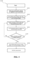
- the most commonly used means of linear inflation control is the feedback control method, which detects the pressure regularly through a pressure sensor and limits the speed of pump inflation within a certain inflation rate to eliminate deviations, so as to obtain an expected system performance, as shown in Fig. 1 , which is a flowchart of a pressurization control method for a conventional blood pressure measurement device with a low-startup-voltage pump.
- the above-mentioned conventional blood pressure measurement device requires a very low startup voltage for the pump, and requires the reduction of inflation rate during the inflation process not to cause noise interference due to the voltage drop being too low at the moment the pump is stopped and then started again. Therefore, the above-mentioned conventional blood pressure measurement device can only inflate the air bag by using a low-startup-voltage pump in the feedback control mode, and cannot be provided with a slow exhaust valve to measure a blood pressure result.
- the above-mentioned blood pressure measurement device controls the low-startup-voltage pump to inflate the air bag via a pulse width modulation (PWM) signal during pressurization and inflation, and continuously captures a current pressure and pulses through a pressure sensor.
- PWM pulse width modulation
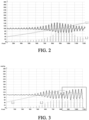
- the air bag can perform the linear pressurization (such as the line L1 shown in Fig. 2 ) until a blood pressure measurement result including diastolic pressure, average pressure, systolic pressure is obtained based on the captured current pressure and its pulse waveform, such as L2 shown in Fig. 2 .
- the conventional blood pressure measurement device uses a high startup voltage pump to shorten the pressurization and inflation time for obtaining blood pressure measurement result
- the conventional blood pressure measurement device measures the pulse waveform by the feedback control method, as shown in Fig. 3 .
- this conventional blood pressure measurement device causes the pump to stop and restart during the pressurization and inflation period, resulting in the pressure falling and then rising again (such as the inflation and pressurization line L1 marked by a frame shown in Fig. 3 ), and resulting in the pulse wave interference (such as a line L2 shown in Fig. 3 ).
- the present invention provides a pressurization control method for blood pressure measurement and a blood pressure measurement device using the same, and the technical solution of the present invention has higher industrial utilization.
- An objective of the present invention is to provide a pressurization control method for blood pressure measurement, the pressurization control method adopts a nonlinear increasing inflation rate and a slow exhaust valve having a nonlinear decreasing depressurization, to achieve linear inflation control.
- the present invention provides a pressurization control method for blood pressure measurement, wherein the pressurization control method is applied on a blood pressure measurement device and includes: connecting an airbag unit with a pump and a pressure sensor; controlling the pump to perform pressurization on the airbag unit with a nonlinear inflation rate until a pulse of a pressure signal outputted from the pressure sensor is interpreted to obtain a blood pressure measurement result.
- the pressurization control method further includes: connecting the airbag unit with a slow exhaust valve unit, wherein the slow exhaust valve unit has a nonlinear depressurization rate.
- the step of controlling the pump with a nonlinear inflation rate further includes: controlling the pump via a pulse width modulation (PWM) signal, wherein the PWM has an adjustable duty cycle; linearly increasing a duty cycle of the PWM signal upon a temporal sequence, to inflate the airbag unit with the nonlinear inflation rate, wherein the slow exhaust valve unit depressurizes the airbag unit with a nonlinear depressurization rate upon the temporal sequence.
- PWM pulse width modulation
- the present invention provides a blood pressure measurement device, include an airbag unit, a pump, a pressure sensor and a processing unit, the airbag unit is connected with the pump and the pressure sensor, and the processing unit is configured to control the pump with a nonlinear inflation rate; when performing pressurization on the airbag unit, the processing unit interprets pulses of a pressure signal outputted from the pressure sensor, to obtain a blood pressure measurement result.
- the processing unit is configured to control the pump with a PWM signal, and the PWM signal has an adjustable duty cycle, and the processing unit linearly increases a duty cycle of the PWM signal upon a temporal sequence.
- the present invention can adopt a high-startup-voltage pump or a low-startup-voltage pump during pressurization and inflation, the method and the blood pressure measurement device of the present invention can prevent the noise interference caused at the moment the pump stops and then restarts, and can achieve linear inflation control.
- a blood pressure measurement device 10 mainly includes a processing unit 11, a display unit 12, a button input unit 13, a pump 14, a pressure sensor 15, an airbag unit 16, a quick exhaust valve unit 17 and a power supply unit (not shown in Fig. 1 ).
- the power supply unit is configured to provide electrical power to component units of the blood pressure measurement device 10.
- the airbag unit 16 can be a cuff airbag unit, the airbag unit 16 is connected with the pump 14, the quick exhaust valve unit 17, and the pressure sensor 15.
- the display unit 12 can be a LCD device.
- the button input unit 13 is configured to provide a user to start a blood pressure measurement mode of the blood pressure measurement device.
- the processing unit 11 includes a storage unit configured to store a program instruction set, and the processing unit 11 executes the program instruction set to execute the pressurization control method for blood pressure measurement, according to the present invention.
- Fig. 5 is a flowchart of a pressurization control method for blood pressure measurement, according to the present invention.
- the blood pressure measurement device 10 does not include a slow exhaust valve unit 18, and adopts a high-startup-voltage pump 14 to perform nonlinear increasing inflation rate on the airbag unit 16 in a feedback control manner. Therefore, when the quick exhaust valve unit 17 is turned off, the processing unit 11 captures a current pressure value through pressure sensor 15; the current pressure value is a value of pressure applied on the airbag unit 16 to inflate with a current inflation rate by the pump 14. After the user operates the button input unit 13 to start the blood pressure measurement mode of the blood pressure measurement device, the processing unit 11 executes the following steps of the pressurization control method for blood pressure measurement, according to the present invention.
- a step 101 the processing unit 11 turns on the pressure sensor 15 to capture the zero pressure of the airbag unit 16.
- the processing unit 11 turns off the quick exhaust valve unit 17, and controls the pump 14 to inflate the airbag unit 16 via a PWM signal.
- the processing unit 11 linearly increases a PWM value to control the pump 14 upon temporal sequence, to make the pump 14 increasingly inflate the airbag unit 16 nonlinearly.
- Fig. 6 shows a schematic view of a linear increasing PWM value according to the present invention.
- the PWM value corresponds to a duty cycle controlled by the PWM signal
- the different PWM value corresponds to different duty cycle.
- the processing unit 11 applies different PWM value to control the pump 14 to inflation the airbag unit 16 with a different inflation rate. As shown in Fig. 6 , upon a temporal sequence, the PWM value is increased linearly over time, to increase the inflation rate of the pump 14 over time to make pressurization faster, such as the line M1 with a nonlinear increasing value in Fig. 7 . Therefore, the processing unit 11 can control the pump 14 to inflate the airbag unit 16 with a nonlinear increasing inflation rate.
- the processing unit 11 When performing pressurization on the airbag unit 16, the processing unit 11 continuously executes a step S104, the processing unit 11 captures the current pressure of the airbag unit 16 through the pressure sensor 15, and interpret the pulse waveform based on the pressure signal outputted from the pressure sensor 15. Next, the processing unit 11 continuously executes a step S105, the processing unit 11 determines whether the blood pressure measurement result including a diastolic pressure, an average pressure and a systolic pressure are obtained based on the waveform and amplitude of the pulses.
- the processing unit 11 determines that the blood pressure measurement result is not obtained yet, the processing unit 11 repeats the step S103, to inflate the airbag unit 16 with the nonlinear increasing inflation rate until the processing unit 11 obtains the blood pressure measurement result including the diastolic pressure, the average pressure and the systolic pressure in the step S105.
- the processing unit 11 executes a step S106 to turn off the pump 14, turn on the quick exhaust valve unit 17 to quickly exhaust the airbag unit 16, and display the blood pressure measurement result including diastolic pressure, average pressure, and systolic pressure on the display unit 12.
- Fig. 8 is a waveform diagram of a pressure signal, pulses, and nonlinear pressurization inflation measured by a first embodiment of the present invention.
- the blood pressure measurement device 10 adopts the high-startup-voltage pump 14 to control the airbag unit 16 with a nonlinear increasing inflation rate in a feedback control manner, such as the inflation pressurization line L1 shown in Fig. 8 .
- the blood pressure measurement device 10 of the present invention does not make the pump stop and then restart during pressurization inflation, to prevent pulse noise interference because the pressure drops and then rises, such as the inflation pressurization line L1 shown in Fig. 3 .
- the first embodiment of the present invention solves the problem caused by the pump which is stopped and then restarted, but causes the problem that the sampling rate is insufficient due to too fast inflation and may result in inaccurate data calculation.
- the present invention further provides a second embodiment of the blood pressure measurement device 10, to solve the problem of the first embodiment having an insufficient sampling rate.
- the blood pressure measurement device 10 further includes a slow exhaust valve unit 18, the airbag unit 16 is connected with the pump 14, the quick exhaust valve unit 17, the slow exhaust valve unit 18, and the pressure sensor 15.
- the slow exhaust valve unit 18 has a nonlinear depressurization rate.
- the line M2 shown in Fig. 7 has a nonlinear decreasing rate, the slow exhaust valve unit 18 depressurizes the airbag unit 16 with a nonlinear depressurization rate upon the temporal sequence.
- the depressurization rate of the slow exhaust valve unit 18 is higher; when the pressure of the airbag unit 16 is lower, the depressurization rate of the slow exhaust valve unit 18 is lower.
- the processing unit 11 similarly executes the steps of the pressurization control method shown in Fig. 5 .
- the steps can refer to the above-mentioned content, so the details are not repeated herein.
- the difference between the first embodiment and the second embodiment is that the pressurization effects applied on the airbag unit 16 are different.
- the blood pressure measurement device 10 can adopt any one of the high-startup-voltage pump 14 and the low-startup-voltage pump 14 to control the airbag unit 16 with nonlinear increasing inflation rate in the feedback control manner; during inflation pressurization, the slow exhaust valve unit 18 is adopted to depressurize the airbag unit 16 with a nonlinear depressurization rate upon a temporal sequence, so that the second embodiment can make the airbag unit 16 have linear pressurization effect, as shown in Fig. 9 , which shows a waveform diagram of a pressure signal, pulses and linear pressurization inflation measured by the second embodiment.
- the blood pressure measurement device 10 does not make the pump stop and then restart, so as to prevent the pressure from dropping and then rising again to cause pulse noise interference, and the linear pressurization effect does not cause the problem that the sampling rate is insufficient and results in inaccurate data calculation.
Landscapes
- Health & Medical Sciences (AREA)
- Life Sciences & Earth Sciences (AREA)
- Cardiology (AREA)
- Vascular Medicine (AREA)
- Heart & Thoracic Surgery (AREA)
- Surgery (AREA)
- Biophysics (AREA)
- Pathology (AREA)
- Engineering & Computer Science (AREA)
- Biomedical Technology (AREA)
- Physiology (AREA)
- Medical Informatics (AREA)
- Molecular Biology (AREA)
- Physics & Mathematics (AREA)
- Animal Behavior & Ethology (AREA)
- General Health & Medical Sciences (AREA)
- Public Health (AREA)
- Veterinary Medicine (AREA)
- Ophthalmology & Optometry (AREA)
- Measuring Pulse, Heart Rate, Blood Pressure Or Blood Flow (AREA)
- External Artificial Organs (AREA)
Abstract
Description
- The present invention relates to a blood pressure measurement device and the pressurization control method, more particularly to a pressurization control method for blood pressure measurement and a blood pressure measurement device using the same.
- High blood pressure is a chronic disease that is common but easily overlooked in Chinese people. Therefore, a blood pressure measurement device is a common blood pressure detection device for families with elderly elders. A conventional blood pressure measurement device needs to control a pump to perform linear inflation for blood pressure measurement. The most commonly used means of linear inflation control is the feedback control method, which detects the pressure regularly through a pressure sensor and limits the speed of pump inflation within a certain inflation rate to eliminate deviations, so as to obtain an expected system performance, as shown in
Fig. 1 , which is a flowchart of a pressurization control method for a conventional blood pressure measurement device with a low-startup-voltage pump. - However, the above-mentioned conventional blood pressure measurement device requires a very low startup voltage for the pump, and requires the reduction of inflation rate during the inflation process not to cause noise interference due to the voltage drop being too low at the moment the pump is stopped and then started again. Therefore, the above-mentioned conventional blood pressure measurement device can only inflate the air bag by using a low-startup-voltage pump in the feedback control mode, and cannot be provided with a slow exhaust valve to measure a blood pressure result. The above-mentioned blood pressure measurement device controls the low-startup-voltage pump to inflate the air bag via a pulse width modulation (PWM) signal during pressurization and inflation, and continuously captures a current pressure and pulses through a pressure sensor. When the difference between the current pressure and the previous pressure is less than a lower limit, the low-startup-voltage pump is controlled to increase an inflation rate; when the difference between the current pressure and the previous pressure is greater than an upper limit, the low-startup-voltage pump is controlled to decrease the inflation rate. Therefore, during the pressurization and inflation period of the above-mentioned conventional blood pressure measurement device, the air bag can perform the linear pressurization (such as the line L1 shown in
Fig. 2 ) until a blood pressure measurement result including diastolic pressure, average pressure, systolic pressure is obtained based on the captured current pressure and its pulse waveform, such as L2 shown inFig. 2 . - When the conventional blood pressure measurement device uses a high startup voltage pump to shorten the pressurization and inflation time for obtaining blood pressure measurement result, the conventional blood pressure measurement device measures the pulse waveform by the feedback control method, as shown in
Fig. 3 . However, this conventional blood pressure measurement device causes the pump to stop and restart during the pressurization and inflation period, resulting in the pressure falling and then rising again (such as the inflation and pressurization line L1 marked by a frame shown inFig. 3 ), and resulting in the pulse wave interference (such as a line L2 shown inFig. 3 ). - Therefore, in order to prevent the noise interference problem caused at the moment the pump stops and restarts, and the present invention provides a pressurization control method for blood pressure measurement and a blood pressure measurement device using the same, and the technical solution of the present invention has higher industrial utilization.
- An objective of the present invention is to provide a pressurization control method for blood pressure measurement, the pressurization control method adopts a nonlinear increasing inflation rate and a slow exhaust valve having a nonlinear decreasing depressurization, to achieve linear inflation control.
- In order to achieve the above-mentioned objective, the present invention provides a pressurization control method for blood pressure measurement, wherein the pressurization control method is applied on a blood pressure measurement device and includes: connecting an airbag unit with a pump and a pressure sensor; controlling the pump to perform pressurization on the airbag unit with a nonlinear inflation rate until a pulse of a pressure signal outputted from the pressure sensor is interpreted to obtain a blood pressure measurement result.
- According to an embodiment of the present invention, the pressurization control method further includes: connecting the airbag unit with a slow exhaust valve unit, wherein the slow exhaust valve unit has a nonlinear depressurization rate.
- According to an embodiment of the present invention, the step of controlling the pump with a nonlinear inflation rate further includes: controlling the pump via a pulse width modulation (PWM) signal, wherein the PWM has an adjustable duty cycle; linearly increasing a duty cycle of the PWM signal upon a temporal sequence, to inflate the airbag unit with the nonlinear inflation rate, wherein the slow exhaust valve unit depressurizes the airbag unit with a nonlinear depressurization rate upon the temporal sequence.
- In order to achieve the above-mentioned objective, the present invention provides a blood pressure measurement device, include an airbag unit, a pump, a pressure sensor and a processing unit, the airbag unit is connected with the pump and the pressure sensor, and the processing unit is configured to control the pump with a nonlinear inflation rate; when performing pressurization on the airbag unit, the processing unit interprets pulses of a pressure signal outputted from the pressure sensor, to obtain a blood pressure measurement result.
- According to an embodiment of the present invention, the processing unit is configured to control the pump with a PWM signal, and the PWM signal has an adjustable duty cycle, and the processing unit linearly increases a duty cycle of the PWM signal upon a temporal sequence.
- According to the above-mentioned pressurization control method for blood pressure measurement and the blood pressure measurement device using the same, the present invention can adopt a high-startup-voltage pump or a low-startup-voltage pump during pressurization and inflation, the method and the blood pressure measurement device of the present invention can prevent the noise interference caused at the moment the pump stops and then restarts, and can achieve linear inflation control.
- The structure, operating principle and effects of the present invention will be described in detail by way of various embodiments which are illustrated in the accompanying drawings.
-
Fig. 1 is a flowchart of a pressurization control method adopting a low startup voltage pump in prior art. -
Fig. 2 is a waveform diagram of a pressure signal, pulses and linear pressurization inflation measured in the pressurization control method ofFig. 1 . -
Fig. 3 is a waveform diagram of a pressure signal, pulses and pressurization inflation measured by conventional technology adopting a high-startup-voltage pump. -
Fig. 4 is a system block diagram of a blood pressure measurement device, according to the present invention. -
Fig. 5 is a flowchart of a pressurization control method for blood pressure measurement, according to the present invention. -
Fig. 6 is a schematic view of a linear increasing value of PWM signal, according to the present invention. -
Fig. 7 is a schematic view of a nonlinear increasing inflation rate of a pump and a nonlinear decreasing depressurization of a slow exhaust valve unit controlled upon temporal sequence. -
Fig. 8 is a waveform diagram of a pressure signal, pulses and nonlinear pressurization inflation measured by a first embodiment of the present invention. -
Fig. 9 is a waveform diagram of a pressure signal, pulses and linear pressurization inflation measure by a second embodiment of the present invention. - The following embodiments of the present invention are herein described in detail with reference to the accompanying drawings. These drawings show specific examples of the embodiments of the present invention. These embodiments are provided so that this disclosure will be thorough and complete, and will fully convey the scope of the invention to those skilled in the art. It is to be acknowledged that these embodiments are exemplary implementations and are not to be construed as limiting the scope of the present invention in any way. Further modifications to the disclosed embodiments, as well as other embodiments, are also included within the scope of the appended claims.
- These embodiments are provided so that this disclosure is thorough and complete, and fully conveys the inventive concept to those skilled in the art. Regarding the drawings, the relative proportions and ratios of elements in the drawings may be exaggerated or diminished in size for the sake of clarity and convenience. Such arbitrary proportions are only illustrative and not limiting in any way. The same reference numbers are used in the drawings and description to refer to the same or like parts. As used herein, the singular forms "a", "an" and "the" are intended to include the plural forms as well, unless the context clearly indicates otherwise.
- It is to be acknowledged that, although the terms 'first', 'second', 'third', and so on, may be used herein to describe various elements, these elements should not be limited by these terms. These terms are used only for the purpose of distinguishing one component from another component. Thus, a first element discussed herein could be termed a second element without altering the description of the present disclosure. As used herein, the term "or" includes any and all combinations of one or more of the associated listed items.
- It will be acknowledged that when an element or layer is referred to as being "on," "connected to" or "coupled to" another element or layer, it can be directly on, connected or coupled to the other element or layer, or intervening elements or layers may be present. In contrast, when an element is referred to as being "directly on," "directly connected to" or "directly coupled to" another element or layer, there are no intervening elements or layers present.
- In addition, unless explicitly described to the contrary, the words "comprise" and "include", and variations such as "comprises", "comprising", "includes", or "including", will be acknowledged to imply the inclusion of stated elements but not the exclusion of any other elements.
- Please refer to
Fig. 4 , which is a system block diagram of a blood pressure measurement device, according to the present invention. In a first embodiment of the present invention, a bloodpressure measurement device 10 mainly includes aprocessing unit 11, adisplay unit 12, abutton input unit 13, apump 14, apressure sensor 15, anairbag unit 16, a quickexhaust valve unit 17 and a power supply unit (not shown inFig. 1 ). The power supply unit is configured to provide electrical power to component units of the bloodpressure measurement device 10. Theairbag unit 16 can be a cuff airbag unit, theairbag unit 16 is connected with thepump 14, the quickexhaust valve unit 17, and thepressure sensor 15. Thedisplay unit 12 can be a LCD device. Thebutton input unit 13 is configured to provide a user to start a blood pressure measurement mode of the blood pressure measurement device. Theprocessing unit 11 includes a storage unit configured to store a program instruction set, and theprocessing unit 11 executes the program instruction set to execute the pressurization control method for blood pressure measurement, according to the present invention. - Please refer to
Fig. 5 , which is a flowchart of a pressurization control method for blood pressure measurement, according to the present invention. In a first embodiment of the present invention, the bloodpressure measurement device 10 does not include a slowexhaust valve unit 18, and adopts a high-startup-voltage pump 14 to perform nonlinear increasing inflation rate on theairbag unit 16 in a feedback control manner. Therefore, when the quickexhaust valve unit 17 is turned off, theprocessing unit 11 captures a current pressure value throughpressure sensor 15; the current pressure value is a value of pressure applied on theairbag unit 16 to inflate with a current inflation rate by thepump 14. After the user operates thebutton input unit 13 to start the blood pressure measurement mode of the blood pressure measurement device, theprocessing unit 11 executes the following steps of the pressurization control method for blood pressure measurement, according to the present invention. - In a
step 101, theprocessing unit 11 turns on thepressure sensor 15 to capture the zero pressure of theairbag unit 16. In a step S102 theprocessing unit 11 turns off the quickexhaust valve unit 17, and controls thepump 14 to inflate theairbag unit 16 via a PWM signal. In a step S103, theprocessing unit 11 linearly increases a PWM value to control thepump 14 upon temporal sequence, to make thepump 14 increasingly inflate theairbag unit 16 nonlinearly. Please refer toFig. 6 , which shows a schematic view of a linear increasing PWM value according to the present invention. The PWM value corresponds to a duty cycle controlled by the PWM signal, the different PWM value corresponds to different duty cycle. Theprocessing unit 11 applies different PWM value to control thepump 14 to inflation theairbag unit 16 with a different inflation rate. As shown inFig. 6 , upon a temporal sequence, the PWM value is increased linearly over time, to increase the inflation rate of thepump 14 over time to make pressurization faster, such as the line M1 with a nonlinear increasing value inFig. 7 . Therefore, theprocessing unit 11 can control thepump 14 to inflate theairbag unit 16 with a nonlinear increasing inflation rate. - When performing pressurization on the
airbag unit 16, theprocessing unit 11 continuously executes a step S104, theprocessing unit 11 captures the current pressure of theairbag unit 16 through thepressure sensor 15, and interpret the pulse waveform based on the pressure signal outputted from thepressure sensor 15. Next, theprocessing unit 11 continuously executes a step S105, theprocessing unit 11 determines whether the blood pressure measurement result including a diastolic pressure, an average pressure and a systolic pressure are obtained based on the waveform and amplitude of the pulses. When theprocessing unit 11 determines that the blood pressure measurement result is not obtained yet, theprocessing unit 11 repeats the step S103, to inflate theairbag unit 16 with the nonlinear increasing inflation rate until theprocessing unit 11 obtains the blood pressure measurement result including the diastolic pressure, the average pressure and the systolic pressure in the step S105. - After obtaining the blood pressure measurement result, the
processing unit 11 executes a step S106 to turn off thepump 14, turn on the quickexhaust valve unit 17 to quickly exhaust theairbag unit 16, and display the blood pressure measurement result including diastolic pressure, average pressure, and systolic pressure on thedisplay unit 12. - Please refer to
Fig. 8 , which is a waveform diagram of a pressure signal, pulses, and nonlinear pressurization inflation measured by a first embodiment of the present invention. In a first embodiment of the present invention, the bloodpressure measurement device 10 adopts the high-startup-voltage pump 14 to control theairbag unit 16 with a nonlinear increasing inflation rate in a feedback control manner, such as the inflation pressurization line L1 shown inFig. 8 . The bloodpressure measurement device 10 of the present invention does not make the pump stop and then restart during pressurization inflation, to prevent pulse noise interference because the pressure drops and then rises, such as the inflation pressurization line L1 shown inFig. 3 . The first embodiment of the present invention solves the problem caused by the pump which is stopped and then restarted, but causes the problem that the sampling rate is insufficient due to too fast inflation and may result in inaccurate data calculation. The present invention further provides a second embodiment of the bloodpressure measurement device 10, to solve the problem of the first embodiment having an insufficient sampling rate. - Please refer to
Fig. 4 , which is a system block diagram of a blood pressure measurement device, according to the present invention. In the second embodiment of the present invention, the bloodpressure measurement device 10 further includes a slowexhaust valve unit 18, theairbag unit 16 is connected with thepump 14, the quickexhaust valve unit 17, the slowexhaust valve unit 18, and thepressure sensor 15. The slowexhaust valve unit 18 has a nonlinear depressurization rate. The line M2 shown inFig. 7 has a nonlinear decreasing rate, the slowexhaust valve unit 18 depressurizes theairbag unit 16 with a nonlinear depressurization rate upon the temporal sequence. When the pressure of theairbag unit 16 is higher, the depressurization rate of the slowexhaust valve unit 18 is higher; when the pressure of theairbag unit 16 is lower, the depressurization rate of the slowexhaust valve unit 18 is lower. - In the second embodiment of the present invention, after the user operates the
button input unit 13 to start a blood pressure measurement mode of the blood pressure measurement device, theprocessing unit 11 similarly executes the steps of the pressurization control method shown inFig. 5 . The steps can refer to the above-mentioned content, so the details are not repeated herein. The difference between the first embodiment and the second embodiment is that the pressurization effects applied on theairbag unit 16 are different. In the second embodiment of the present invention, the bloodpressure measurement device 10 can adopt any one of the high-startup-voltage pump 14 and the low-startup-voltage pump 14 to control theairbag unit 16 with nonlinear increasing inflation rate in the feedback control manner; during inflation pressurization, the slowexhaust valve unit 18 is adopted to depressurize theairbag unit 16 with a nonlinear depressurization rate upon a temporal sequence, so that the second embodiment can make theairbag unit 16 have linear pressurization effect, as shown inFig. 9 , which shows a waveform diagram of a pressure signal, pulses and linear pressurization inflation measured by the second embodiment. In the second embodiment of the present invention, the bloodpressure measurement device 10 does not make the pump stop and then restart, so as to prevent the pressure from dropping and then rising again to cause pulse noise interference, and the linear pressurization effect does not cause the problem that the sampling rate is insufficient and results in inaccurate data calculation. - The present invention disclosed herein has been described by means of specific embodiments. However, numerous modifications, variations and enhancements can be made thereto by those skilled in the art without departing from the spirit and scope of the disclosure set forth in the claims.
Claims (12)
- A pressurization control method for blood pressure measurement, characterized in that the pressurization control method is applied on a blood pressure measurement device (10) and comprises:connecting an airbag unit (16) with a pump (14) and a pressure sensor (15); andcontrolling the pump (14) to perform pressurization on the airbag unit (16) with a nonlinear inflation rate until a pulse of a pressure signal outputted from the pressure sensor (15) is interpreted to obtain a blood pressure measurement result.
- The pressurization control method according to claim 1, characterized in further comprising:
connecting the airbag unit (16) with a slow exhaust valve unit (18), wherein the slow exhaust valve unit (18) has a nonlinear depressurization rate. - The pressurization control method according to claim 2, characterized in that controlling the pump (14) with the nonlinear inflation rate comprises:
controlling the pump (14) via a pulse width modulation (PWM) signal, wherein the PWM has an adjustable duty cycle. - The pressurization control method according to claim 3, characterized in that controlling the pump (14) with the nonlinear inflation rate comprising:
linearly increasing a duty cycle of the PWM signal upon a temporal sequence. - The pressurization control method according to claim 4, characterized in that the pump (14) inflates the airbag unit (16) with the nonlinear inflation rate upon the temporal sequence, and the slow exhaust valve unit (18) depressurizes the airbag unit (16) with a nonlinear depressurization rate upon the temporal sequence.
- The pressurization control method according to claim 4, characterized in that the airbag unit (16) performs a quasi-linear pressurization process upon the temporal sequence.
- The pressurization control method according to claim 6, characterized in that when the pressure of the airbag unit (16) is higher, the depressurization rate of the slow exhaust valve unit (18) is higher, and when the pressure of the airbag unit (16) is lower, the depressurization rate of the slow exhaust valve unit (18) is lower.
- The pressurization control method according to claim 1, characterized in that controlling the pump (14) with a nonlinear inflation rate comprising:
controlling the pump (14) with the PWM signal, wherein the PWM has a duty cycle, and the duty cycle of the PWM signal is linearly increased upon a temporal sequence. - The pressurization control method according to claim 1, characterized in further comprising:connecting the airbag unit (16) with a quick exhaust valve unit (17); andafter the blood pressure measurement result is obtained, turning on the quick exhaust valve unit (17) to quickly depressurize the airbag unit (16).
- A blood pressure measurement device (10) performing the pressurization control method according to one of claims 1 to 9.
- The blood pressure measurement device (10) according to claim 10, characterized in further comprising:
a processing unit (11), configured to control the pump (14) to pressurize the airbag unit (16) with a nonlinear inflation rate. - The blood pressure measurement device (10) according to claim 11, characterized in that the processing unit (11) interprets the pulses of the pressure signal outputted from the pressure sensor (15), to obtain the blood pressure measurement result, and displays the blood pressure measurement result on a display unit (12).
Applications Claiming Priority (1)
| Application Number | Priority Date | Filing Date | Title |
|---|---|---|---|
| TW111132749A TWI813432B (en) | 2022-08-30 | 2022-08-30 | Pressurization control method for blood pressure measurement and blood pressure machine using the pressurization control method |
Publications (3)
| Publication Number | Publication Date |
|---|---|
| EP4331478A1 true EP4331478A1 (en) | 2024-03-06 |
| EP4331478C0 EP4331478C0 (en) | 2025-11-12 |
| EP4331478B1 EP4331478B1 (en) | 2025-11-12 |
Family
ID=87473812
Family Applications (1)
| Application Number | Title | Priority Date | Filing Date |
|---|---|---|---|
| EP23187506.3A Active EP4331478B1 (en) | 2022-08-30 | 2023-07-25 | Pressurization control method for blood pressure measurement and blood pressure measurement device using the same |
Country Status (4)
| Country | Link |
|---|---|
| US (1) | US20240065562A1 (en) |
| EP (1) | EP4331478B1 (en) |
| JP (1) | JP7770363B2 (en) |
| TW (1) | TWI813432B (en) |
Cited By (1)
| Publication number | Priority date | Publication date | Assignee | Title |
|---|---|---|---|---|
| US20240065562A1 (en) * | 2022-08-30 | 2024-02-29 | Avita Corporation | Pressurization control method for blood pressure measurement and blood pressure measurement device using the same |
Citations (3)
| Publication number | Priority date | Publication date | Assignee | Title |
|---|---|---|---|---|
| CN1394546A (en) * | 2002-08-08 | 2003-02-05 | 天津市先石光学技术有限公司 | Blood pressure measuring device and method |
| US20110152650A1 (en) * | 2009-12-21 | 2011-06-23 | General Electric Company | Adaptive pump control during non-invasive blood pressure measurement |
| US20190099092A1 (en) * | 2017-09-29 | 2019-04-04 | Fitbit, Inc. | Finger blood pressure cuff |
Family Cites Families (21)
| Publication number | Priority date | Publication date | Assignee | Title |
|---|---|---|---|---|
| CA1275449C (en) * | 1984-11-27 | 1990-10-23 | J. Stanford Hutcheson | Portable automated blood pressure monitoring apparatus and method |
| US4889132A (en) * | 1986-09-26 | 1989-12-26 | The University Of North Carolina At Chapel Hill | Portable automated blood pressure monitoring apparatus and method |
| JPH06105814A (en) * | 1992-09-25 | 1994-04-19 | Matsushita Electric Works Ltd | Constant speed exhaust valve device for blood pressure monitor |
| JPH10137204A (en) * | 1996-11-12 | 1998-05-26 | Hioki Ee Corp | Non-invasive sphygmomanometer |
| US6093152A (en) * | 1998-10-30 | 2000-07-25 | Protocol Systems, Inc. | Pulse width modulation valve control for vital sign monitors |
| KR100745747B1 (en) * | 2001-08-21 | 2007-08-02 | 삼성전자주식회사 | Blood pressure measurement device and method using air pressure that can be changed linearly |
| TWI275381B (en) * | 2005-04-11 | 2007-03-11 | Dailycare Biomedical Inc | An apparatus and method for measurement of pulse wave base on blood pressure method |
| JP4794278B2 (en) | 2005-11-08 | 2011-10-19 | 株式会社エルクエスト | Blood pressure measurement device |
| JP4153543B2 (en) * | 2006-10-27 | 2008-09-24 | シチズンホールディングス株式会社 | Electronic blood pressure monitor |
| US20100292586A1 (en) * | 2009-05-13 | 2010-11-18 | Rooke Thom W | Wireless automatic ankle-brachial index (AABI) measurement system |
| WO2016126445A1 (en) * | 2015-02-02 | 2016-08-11 | Midmark Corporation | System and method for non-invasive blood pressure measurement |
| US10939832B2 (en) * | 2015-02-11 | 2021-03-09 | Microlife Intellectual Property Gmbh | Device and method for measuring blood pressure and for indication of the presence of atrial fibrillation |
| MX2018013616A (en) | 2016-05-13 | 2019-02-21 | Amgen Inc | Vial sleeve assembly. |
| CN106108877B (en) * | 2016-06-03 | 2017-09-26 | 广州中科新知科技有限公司 | A kind of survey meter of blood pressure |
| TWI604821B (en) * | 2016-11-11 | 2017-11-11 | Microlife Corp | Blood pressure measuring device with piezoelectric pump and control method for blood pressure measuring device with piezoelectric pump |
| WO2018135553A1 (en) | 2017-01-20 | 2018-07-26 | 株式会社村田製作所 | Fluid control device and sphygmomanometer |
| CN111265201A (en) * | 2018-12-04 | 2020-06-12 | 爱奥乐医疗器械(深圳)有限公司 | Intelligent sphygmomanometer, intelligent sphygmomanometer system and blood pressure measuring method |
| JP7367478B2 (en) | 2019-11-14 | 2023-10-24 | オムロンヘルスケア株式会社 | Blood pressure monitor, blood pressure measurement method, and program |
| CN113827211B (en) * | 2021-08-09 | 2024-12-06 | 研和智能科技(杭州)有限公司 | A blood pressure measurement and calculation method based on multiple signals |
| TWI813432B (en) * | 2022-08-30 | 2023-08-21 | 豪展醫療科技股份有限公司 | Pressurization control method for blood pressure measurement and blood pressure machine using the pressurization control method |
| CN117898690B (en) * | 2024-03-19 | 2024-05-24 | 深圳市微克科技股份有限公司 | Inflation control method, system and storage medium for watch-type blood pressure detection |
-
2022
- 2022-08-30 TW TW111132749A patent/TWI813432B/en active
-
2023
- 2023-07-25 EP EP23187506.3A patent/EP4331478B1/en active Active
- 2023-07-28 US US18/227,309 patent/US20240065562A1/en active Pending
- 2023-08-10 JP JP2023130737A patent/JP7770363B2/en active Active
Patent Citations (3)
| Publication number | Priority date | Publication date | Assignee | Title |
|---|---|---|---|---|
| CN1394546A (en) * | 2002-08-08 | 2003-02-05 | 天津市先石光学技术有限公司 | Blood pressure measuring device and method |
| US20110152650A1 (en) * | 2009-12-21 | 2011-06-23 | General Electric Company | Adaptive pump control during non-invasive blood pressure measurement |
| US20190099092A1 (en) * | 2017-09-29 | 2019-04-04 | Fitbit, Inc. | Finger blood pressure cuff |
Cited By (1)
| Publication number | Priority date | Publication date | Assignee | Title |
|---|---|---|---|---|
| US20240065562A1 (en) * | 2022-08-30 | 2024-02-29 | Avita Corporation | Pressurization control method for blood pressure measurement and blood pressure measurement device using the same |
Also Published As
| Publication number | Publication date |
|---|---|
| EP4331478C0 (en) | 2025-11-12 |
| US20240065562A1 (en) | 2024-02-29 |
| JP7770363B2 (en) | 2025-11-14 |
| TWI813432B (en) | 2023-08-21 |
| TW202408418A (en) | 2024-03-01 |
| JP2024035108A (en) | 2024-03-13 |
| EP4331478B1 (en) | 2025-11-12 |
Similar Documents
| Publication | Publication Date | Title |
|---|---|---|
| CN109715053B (en) | Sensor localization using electroactive polymers | |
| US20250152024A1 (en) | Blood pressure measurement device with a mems pump and control method for the same | |
| US10130270B2 (en) | Electronic blood pressure monitor | |
| US10349842B2 (en) | Blood pressure measuring apparatus | |
| CN105286838B (en) | A kind of the pump speed Automatic adjustment method and device of boosting blood pressure measurement | |
| JP4213188B2 (en) | Electronic blood pressure monitor | |
| EP4331478B1 (en) | Pressurization control method for blood pressure measurement and blood pressure measurement device using the same | |
| RU2555111C2 (en) | Electronic sphygmomanometer | |
| JP2013144055A5 (en) | ||
| WO2008050786A1 (en) | Electronic sphygmometer | |
| CN100488446C (en) | Intelligent pressurization control device | |
| US11122984B2 (en) | Pulse wave detection device, biological information measurement device, and control method for pulse wave detection device | |
| JP2936815B2 (en) | Electronic sphygmomanometer | |
| JP2002143106A (en) | Electronic sphygmomanometer | |
| US20240164979A1 (en) | System, method and device for monitoring and expressing compliance of a medical treatment | |
| JP6807689B2 (en) | Cuff pressure control device, its control method, and biometric information measurement device | |
| JP3975834B2 (en) | Biological information measuring device | |
| US20190046046A1 (en) | Pulse wave detection device, biological information measurement device, and control method for pulse wave detection device | |
| JPH01136631A (en) | Blood pressure measuring apparatus | |
| JPH0763451B2 (en) | Electronic blood pressure monitor | |
| JP2025502915A (en) | Dual mode non-invasive blood pressure measurement | |
| JPH0779800B2 (en) | Electronic blood pressure monitor | |
| JPH0531081A (en) | Blood pressure measurement device |
Legal Events
| Date | Code | Title | Description |
|---|---|---|---|
| PUAI | Public reference made under article 153(3) epc to a published international application that has entered the european phase |
Free format text: ORIGINAL CODE: 0009012 |
|
| STAA | Information on the status of an ep patent application or granted ep patent |
Free format text: STATUS: THE APPLICATION HAS BEEN PUBLISHED |
|
| AK | Designated contracting states |
Kind code of ref document: A1 Designated state(s): AL AT BE BG CH CY CZ DE DK EE ES FI FR GB GR HR HU IE IS IT LI LT LU LV MC ME MK MT NL NO PL PT RO RS SE SI SK SM TR |
|
| STAA | Information on the status of an ep patent application or granted ep patent |
Free format text: STATUS: REQUEST FOR EXAMINATION WAS MADE |
|
| 17P | Request for examination filed |
Effective date: 20240506 |
|
| RBV | Designated contracting states (corrected) |
Designated state(s): AL AT BE BG CH CY CZ DE DK EE ES FI FR GB GR HR HU IE IS IT LI LT LU LV MC ME MK MT NL NO PL PT RO RS SE SI SK SM TR |
|
| GRAP | Despatch of communication of intention to grant a patent |
Free format text: ORIGINAL CODE: EPIDOSNIGR1 |
|
| RIC1 | Information provided on ipc code assigned before grant |
Ipc: A61B 5/021 20060101AFI20250721BHEP Ipc: A61B 5/022 20060101ALI20250721BHEP Ipc: A61B 5/0225 20060101ALI20250721BHEP Ipc: A61B 5/0235 20060101ALI20250721BHEP |
|
| STAA | Information on the status of an ep patent application or granted ep patent |
Free format text: STATUS: GRANT OF PATENT IS INTENDED |
|
| INTG | Intention to grant announced |
Effective date: 20250828 |
|
| GRAS | Grant fee paid |
Free format text: ORIGINAL CODE: EPIDOSNIGR3 |
|
| GRAA | (expected) grant |
Free format text: ORIGINAL CODE: 0009210 |
|
| STAA | Information on the status of an ep patent application or granted ep patent |
Free format text: STATUS: THE PATENT HAS BEEN GRANTED |
|
| AK | Designated contracting states |
Kind code of ref document: B1 Designated state(s): AL AT BE BG CH CY CZ DE DK EE ES FI FR GB GR HR HU IE IS IT LI LT LU LV MC ME MK MT NL NO PL PT RO RS SE SI SK SM TR |
|
| REG | Reference to a national code |
Ref country code: CH Ref legal event code: F10 Free format text: ST27 STATUS EVENT CODE: U-0-0-F10-F00 (AS PROVIDED BY THE NATIONAL OFFICE) Effective date: 20251112 Ref country code: GB Ref legal event code: FG4D |
|
| REG | Reference to a national code |
Ref country code: DE Ref legal event code: R096 Ref document number: 602023008483 Country of ref document: DE |
|
| REG | Reference to a national code |
Ref country code: IE Ref legal event code: FG4D |
|
| U01 | Request for unitary effect filed |
Effective date: 20251112 |
|
| U07 | Unitary effect registered |
Designated state(s): AT BE BG DE DK EE FI FR IT LT LU LV MT NL PT RO SE SI Effective date: 20251209 |
|
| PG25 | Lapsed in a contracting state [announced via postgrant information from national office to epo] |
Ref country code: ES Free format text: LAPSE BECAUSE OF FAILURE TO SUBMIT A TRANSLATION OF THE DESCRIPTION OR TO PAY THE FEE WITHIN THE PRESCRIBED TIME-LIMIT Effective date: 20251112 |
|
| PG25 | Lapsed in a contracting state [announced via postgrant information from national office to epo] |
Ref country code: NO Free format text: LAPSE BECAUSE OF FAILURE TO SUBMIT A TRANSLATION OF THE DESCRIPTION OR TO PAY THE FEE WITHIN THE PRESCRIBED TIME-LIMIT Effective date: 20260212 |
|
| PG25 | Lapsed in a contracting state [announced via postgrant information from national office to epo] |
Ref country code: HR Free format text: LAPSE BECAUSE OF FAILURE TO SUBMIT A TRANSLATION OF THE DESCRIPTION OR TO PAY THE FEE WITHIN THE PRESCRIBED TIME-LIMIT Effective date: 20251112 |
|
| PG25 | Lapsed in a contracting state [announced via postgrant information from national office to epo] |
Ref country code: RS Free format text: LAPSE BECAUSE OF FAILURE TO SUBMIT A TRANSLATION OF THE DESCRIPTION OR TO PAY THE FEE WITHIN THE PRESCRIBED TIME-LIMIT Effective date: 20260212 |
|
| PG25 | Lapsed in a contracting state [announced via postgrant information from national office to epo] |
Ref country code: IS Free format text: LAPSE BECAUSE OF FAILURE TO SUBMIT A TRANSLATION OF THE DESCRIPTION OR TO PAY THE FEE WITHIN THE PRESCRIBED TIME-LIMIT Effective date: 20260312 |
|
| PG25 | Lapsed in a contracting state [announced via postgrant information from national office to epo] |
Ref country code: PL Free format text: LAPSE BECAUSE OF FAILURE TO SUBMIT A TRANSLATION OF THE DESCRIPTION OR TO PAY THE FEE WITHIN THE PRESCRIBED TIME-LIMIT Effective date: 20251112 |
|
| PG25 | Lapsed in a contracting state [announced via postgrant information from national office to epo] |
Ref country code: SM Free format text: LAPSE BECAUSE OF FAILURE TO SUBMIT A TRANSLATION OF THE DESCRIPTION OR TO PAY THE FEE WITHIN THE PRESCRIBED TIME-LIMIT Effective date: 20251112 |
|
| PG25 | Lapsed in a contracting state [announced via postgrant information from national office to epo] |
Ref country code: CZ Free format text: LAPSE BECAUSE OF FAILURE TO SUBMIT A TRANSLATION OF THE DESCRIPTION OR TO PAY THE FEE WITHIN THE PRESCRIBED TIME-LIMIT Effective date: 20251112 |
|
| PG25 | Lapsed in a contracting state [announced via postgrant information from national office to epo] |
Ref country code: SK Free format text: LAPSE BECAUSE OF FAILURE TO SUBMIT A TRANSLATION OF THE DESCRIPTION OR TO PAY THE FEE WITHIN THE PRESCRIBED TIME-LIMIT Effective date: 20251112 |