EP4330964B1 - Context aware audio processing - Google Patents
Context aware audio processing Download PDFInfo
- Publication number
- EP4330964B1 EP4330964B1 EP22724316.9A EP22724316A EP4330964B1 EP 4330964 B1 EP4330964 B1 EP 4330964B1 EP 22724316 A EP22724316 A EP 22724316A EP 4330964 B1 EP4330964 B1 EP 4330964B1
- Authority
- EP
- European Patent Office
- Prior art keywords
- audio
- audio recording
- context
- frequency
- speech frame
- Prior art date
- Legal status (The legal status is an assumption and is not a legal conclusion. Google has not performed a legal analysis and makes no representation as to the accuracy of the status listed.)
- Active
Links
Images

Classifications
-
- G—PHYSICS
- G10—MUSICAL INSTRUMENTS; ACOUSTICS
- G10L—SPEECH ANALYSIS TECHNIQUES OR SPEECH SYNTHESIS; SPEECH RECOGNITION; SPEECH OR VOICE PROCESSING TECHNIQUES; SPEECH OR AUDIO CODING OR DECODING
- G10L21/00—Speech or voice signal processing techniques to produce another audible or non-audible signal, e.g. visual or tactile, in order to modify its quality or its intelligibility
- G10L21/02—Speech enhancement, e.g. noise reduction or echo cancellation
- G10L21/0208—Noise filtering
- G10L21/0216—Noise filtering characterised by the method used for estimating noise
-
- G—PHYSICS
- G10—MUSICAL INSTRUMENTS; ACOUSTICS
- G10L—SPEECH ANALYSIS TECHNIQUES OR SPEECH SYNTHESIS; SPEECH RECOGNITION; SPEECH OR VOICE PROCESSING TECHNIQUES; SPEECH OR AUDIO CODING OR DECODING
- G10L21/00—Speech or voice signal processing techniques to produce another audible or non-audible signal, e.g. visual or tactile, in order to modify its quality or its intelligibility
- G10L21/02—Speech enhancement, e.g. noise reduction or echo cancellation
- G10L21/0316—Speech enhancement, e.g. noise reduction or echo cancellation by changing the amplitude
- G10L21/0324—Details of processing therefor
- G10L21/034—Automatic adjustment
-
- G—PHYSICS
- G10—MUSICAL INSTRUMENTS; ACOUSTICS
- G10L—SPEECH ANALYSIS TECHNIQUES OR SPEECH SYNTHESIS; SPEECH RECOGNITION; SPEECH OR VOICE PROCESSING TECHNIQUES; SPEECH OR AUDIO CODING OR DECODING
- G10L21/00—Speech or voice signal processing techniques to produce another audible or non-audible signal, e.g. visual or tactile, in order to modify its quality or its intelligibility
- G10L21/02—Speech enhancement, e.g. noise reduction or echo cancellation
- G10L21/0316—Speech enhancement, e.g. noise reduction or echo cancellation by changing the amplitude
- G10L21/0364—Speech enhancement, e.g. noise reduction or echo cancellation by changing the amplitude for improving intelligibility
-
- G—PHYSICS
- G10—MUSICAL INSTRUMENTS; ACOUSTICS
- G10L—SPEECH ANALYSIS TECHNIQUES OR SPEECH SYNTHESIS; SPEECH RECOGNITION; SPEECH OR VOICE PROCESSING TECHNIQUES; SPEECH OR AUDIO CODING OR DECODING
- G10L25/00—Speech or voice analysis techniques not restricted to a single one of groups G10L15/00 - G10L21/00
- G10L25/03—Speech or voice analysis techniques not restricted to a single one of groups G10L15/00 - G10L21/00 characterised by the type of extracted parameters
- G10L25/18—Speech or voice analysis techniques not restricted to a single one of groups G10L15/00 - G10L21/00 characterised by the type of extracted parameters the extracted parameters being spectral information of each sub-band
-
- G—PHYSICS
- G10—MUSICAL INSTRUMENTS; ACOUSTICS
- G10L—SPEECH ANALYSIS TECHNIQUES OR SPEECH SYNTHESIS; SPEECH RECOGNITION; SPEECH OR VOICE PROCESSING TECHNIQUES; SPEECH OR AUDIO CODING OR DECODING
- G10L25/00—Speech or voice analysis techniques not restricted to a single one of groups G10L15/00 - G10L21/00
- G10L25/27—Speech or voice analysis techniques not restricted to a single one of groups G10L15/00 - G10L21/00 characterised by the analysis technique
- G10L25/30—Speech or voice analysis techniques not restricted to a single one of groups G10L15/00 - G10L21/00 characterised by the analysis technique using neural networks
-
- G—PHYSICS
- G10—MUSICAL INSTRUMENTS; ACOUSTICS
- G10L—SPEECH ANALYSIS TECHNIQUES OR SPEECH SYNTHESIS; SPEECH RECOGNITION; SPEECH OR VOICE PROCESSING TECHNIQUES; SPEECH OR AUDIO CODING OR DECODING
- G10L25/00—Speech or voice analysis techniques not restricted to a single one of groups G10L15/00 - G10L21/00
- G10L25/78—Detection of presence or absence of voice signals
-
- H—ELECTRICITY
- H04—ELECTRIC COMMUNICATION TECHNIQUE
- H04R—LOUDSPEAKERS, MICROPHONES, GRAMOPHONE PICK-UPS OR LIKE ACOUSTIC ELECTROMECHANICAL TRANSDUCERS; DEAF-AID SETS; PUBLIC ADDRESS SYSTEMS
- H04R1/00—Details of transducers, loudspeakers or microphones
- H04R1/10—Earpieces; Attachments therefor ; Earphones; Monophonic headphones
- H04R1/1083—Reduction of ambient noise
-
- H—ELECTRICITY
- H04—ELECTRIC COMMUNICATION TECHNIQUE
- H04R—LOUDSPEAKERS, MICROPHONES, GRAMOPHONE PICK-UPS OR LIKE ACOUSTIC ELECTROMECHANICAL TRANSDUCERS; DEAF-AID SETS; PUBLIC ADDRESS SYSTEMS
- H04R1/00—Details of transducers, loudspeakers or microphones
- H04R1/10—Earpieces; Attachments therefor ; Earphones; Monophonic headphones
- H04R1/1091—Details not provided for in groups H04R1/1008 - H04R1/1083
-
- H—ELECTRICITY
- H04—ELECTRIC COMMUNICATION TECHNIQUE
- H04R—LOUDSPEAKERS, MICROPHONES, GRAMOPHONE PICK-UPS OR LIKE ACOUSTIC ELECTROMECHANICAL TRANSDUCERS; DEAF-AID SETS; PUBLIC ADDRESS SYSTEMS
- H04R3/00—Circuits for transducers, loudspeakers or microphones
- H04R3/005—Circuits for transducers, loudspeakers or microphones for combining the signals of two or more microphones
-
- H—ELECTRICITY
- H04—ELECTRIC COMMUNICATION TECHNIQUE
- H04S—STEREOPHONIC SYSTEMS
- H04S7/00—Indicating arrangements; Control arrangements, e.g. balance control
- H04S7/30—Control circuits for electronic adaptation of the sound field
- H04S7/302—Electronic adaptation of stereophonic sound system to listener position or orientation
- H04S7/303—Tracking of listener position or orientation
- H04S7/304—For headphones
-
- H—ELECTRICITY
- H04—ELECTRIC COMMUNICATION TECHNIQUE
- H04R—LOUDSPEAKERS, MICROPHONES, GRAMOPHONE PICK-UPS OR LIKE ACOUSTIC ELECTROMECHANICAL TRANSDUCERS; DEAF-AID SETS; PUBLIC ADDRESS SYSTEMS
- H04R1/00—Details of transducers, loudspeakers or microphones
- H04R1/10—Earpieces; Attachments therefor ; Earphones; Monophonic headphones
- H04R1/1016—Earpieces of the intra-aural type
-
- H—ELECTRICITY
- H04—ELECTRIC COMMUNICATION TECHNIQUE
- H04R—LOUDSPEAKERS, MICROPHONES, GRAMOPHONE PICK-UPS OR LIKE ACOUSTIC ELECTROMECHANICAL TRANSDUCERS; DEAF-AID SETS; PUBLIC ADDRESS SYSTEMS
- H04R1/00—Details of transducers, loudspeakers or microphones
- H04R1/20—Arrangements for obtaining desired frequency or directional characteristics
- H04R1/32—Arrangements for obtaining desired frequency or directional characteristics for obtaining desired directional characteristic only
- H04R1/40—Arrangements for obtaining desired frequency or directional characteristics for obtaining desired directional characteristic only by combining a number of identical transducers
- H04R1/406—Arrangements for obtaining desired frequency or directional characteristics for obtaining desired directional characteristic only by combining a number of identical transducers microphones
-
- H—ELECTRICITY
- H04—ELECTRIC COMMUNICATION TECHNIQUE
- H04R—LOUDSPEAKERS, MICROPHONES, GRAMOPHONE PICK-UPS OR LIKE ACOUSTIC ELECTROMECHANICAL TRANSDUCERS; DEAF-AID SETS; PUBLIC ADDRESS SYSTEMS
- H04R2201/00—Details of transducers, loudspeakers or microphones covered by H04R1/00 but not provided for in any of its subgroups
- H04R2201/10—Details of earpieces, attachments therefor, earphones or monophonic headphones covered by H04R1/10 but not provided for in any of its subgroups
- H04R2201/107—Monophonic and stereophonic headphones with microphone for two-way hands free communication
-
- H—ELECTRICITY
- H04—ELECTRIC COMMUNICATION TECHNIQUE
- H04R—LOUDSPEAKERS, MICROPHONES, GRAMOPHONE PICK-UPS OR LIKE ACOUSTIC ELECTROMECHANICAL TRANSDUCERS; DEAF-AID SETS; PUBLIC ADDRESS SYSTEMS
- H04R2420/00—Details of connection covered by H04R, not provided for in its groups
- H04R2420/01—Input selection or mixing for amplifiers or loudspeakers
-
- H—ELECTRICITY
- H04—ELECTRIC COMMUNICATION TECHNIQUE
- H04R—LOUDSPEAKERS, MICROPHONES, GRAMOPHONE PICK-UPS OR LIKE ACOUSTIC ELECTROMECHANICAL TRANSDUCERS; DEAF-AID SETS; PUBLIC ADDRESS SYSTEMS
- H04R2499/00—Aspects covered by H04R or H04S not otherwise provided for in their subgroups
- H04R2499/10—General applications
- H04R2499/11—Transducers incorporated or for use in hand-held devices, e.g. mobile phones, PDA's, camera's
-
- H—ELECTRICITY
- H04—ELECTRIC COMMUNICATION TECHNIQUE
- H04R—LOUDSPEAKERS, MICROPHONES, GRAMOPHONE PICK-UPS OR LIKE ACOUSTIC ELECTROMECHANICAL TRANSDUCERS; DEAF-AID SETS; PUBLIC ADDRESS SYSTEMS
- H04R5/00—Stereophonic arrangements
- H04R5/04—Circuit arrangements, e.g. for selective connection of amplifier inputs/outputs to loudspeakers, for loudspeaker detection, or for adaptation of settings to personal preferences or hearing impairments
-
- H—ELECTRICITY
- H04—ELECTRIC COMMUNICATION TECHNIQUE
- H04S—STEREOPHONIC SYSTEMS
- H04S2400/00—Details of stereophonic systems covered by H04S but not provided for in its groups
- H04S2400/15—Aspects of sound capture and related signal processing for recording or reproduction
Definitions
- This disclosure relates generally to audio signal processing, and more particularly to processing user-generated content (UGC).
- ULC user-generated content
- UGC is typically created by consumers and can include any form of content (e.g., images, videos, text, audio).
- UGC is typically posted by its creator to online platforms, including but not limited to social media, blogs, wikis and the like.
- One trend related to UGC is personal moment sharing in variable environments (e.g., indoors, outdoors, by the sea) by recording video and audio using a personal mobile device (e.g., smart phone, tablet computer, wearable devices).
- Most UGC content contains audio artifacts due to consumer hardware limitations and a non-professional recording environment.
- the traditional way of UGC processing is based on audio signal analysis or artificial intelligence (Al) based noise reduction and enhancement processing.
- Al artificial intelligence
- One difficulty in processing UGC is how to treat different sound types in different audio environments while maintaining the creative objective of content creator.
- Prior art document EP 2 508 010 A1 discloses a method for denoising audio based on detected context using sensors. The processing parameters are selected according to the context and the parameters steer the denoising beam.
- connecting elements such as solid or dashed lines or arrows
- the absence of any such connecting elements is not meant to imply that no connection, relationship, or association can exist.
- some connections, relationships, or associations between elements are not shown in the drawings so as not to obscure the disclosure.
- a single connecting element is used to represent multiple connections, relationships or associations between elements.
- a connecting element represents a communication of signals, data, or instructions
- such element represents one or multiple signal paths, as may be needed, to affect the communication.
- the term “includes” and its variants are to be read as open-ended terms that mean “includes, but is not limited to.”
- the term “or” is to be read as “and/or” unless the context clearly indicates otherwise.
- the term “based on” is to be read as “based at least in part on.”
- the term “one example embodiment” and “an example embodiment” are to be read as “at least one example embodiment.”
- the term “another embodiment” is to be read as “at least one other embodiment.”
- the terms “determined,” “determines,” or “determining” are to be read as obtaining, receiving, computing, calculating, estimating, predicting or deriving.
- all technical and scientific terms used herein have the same meaning as commonly understood by one of ordinary skills in the art to which this disclosure belongs.
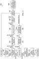
- FIG. 1 illustrates binaural recording using earbuds and a mobile device, according to an embodiment.
- System 100 includes a two-step process of recording video with a video camera of a mobile device 101 (e.g., a smartphone), and concurrently recording audio associated with the video recording.
- the audio recording can be made by, for example, mobile device 101 recording audio signals output by microphones embedded in earbuds 102.
- the audio signals can include but are not limited to comments spoken by a user and/or ambient sound. If both the left and right microphones are used then a binaural recording can be captured.
- microphones embedded or attached to mobile device 101 can also be used.
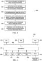
- FIG. 2 is a block diagram of a system 200 for context aware audio processing, according to an embodiment.
- System 200 includes window processor 202, spectrum analyzer 203, band feature analyzer 204, gain estimator 205, machine learning model 2006, context analyzer 207, gain analyzer/adjuster 209, band gain to bin gain converter 210, spectrum modifier 211, speech reconstructor 212 and window overlap-add processor 213.
- Window processor 202 generates a speech frame comprising overlapping windows of samples of input audio 201 containing speech (e.g., an audio recording captured by mobile device 101).
- the speech frame is input into spectrum analyzer 203 which generates frequency bin features and a fundamental frequency (F0).
- the analyzed spectrum information can be represented by: Fast Fourier transform (FFT) spectrum, Quadrature Mirror Filter (QMF) features or any other audio analysis process.
- FFT Fast Fourier transform
- QMF Quadrature Mirror Filter
- the bins are scaled by spectrum modifier 211 and input into speech reconstructor 212 which outputs a reconstructed speech frame.
- the reconstructed speech frame is input into window overlap-add processor 213, which generates output speech.
- band features and F0 are input into band feature analyzer 204, which outputs band features and F0.
- the band features are extracted based on FFT parameters.
- Band features can include but are not limited to: MFCC and BFCC.
- a band harmonicity feature can be computed, which indicates how much a current frequency band is composed of a periodic signal.
- the harmonicity feature can be calculated based on FFT frequency bins of a current speech frame.
- the harmonicity feature is calculated by a correlation between the current speech frame and a previous speech frame.
- the band features and F0 are input into gain estimator 205 which estimates gains ( CGains ) for noise reduction based on a model selected from model pool 206.
- the model is selected based on a model number output by context analyzer 207 in response to input visual information and other sensor information.
- the model is a deep neural network (DNN) trained to estimate gains and VAD for each frequency band based on the band features and F0.
- the DNN model can be based on a fully connected neural network (FCNN), recurrent neural network (RNN) or convolutional neural network (CNN) or any combination of FCNN, RNN and CNN.
- a Wiener Filter or other suitable estimator can be combined with the DNN model to get the final estimated gains for noise reduction.
- the estimated gains, CGains are input into gain analyzer/adjuster 209 which generates adjusted gains, AGains, based on an audio processing profile.
- the adjusted gains, AGains is input into band gain to bin gain converter 210, which generates adjusted bin gains.
- the adjusted bin gains are input spectrum modifier 211 which applies the adjusted bin gains to their corresponding frequency bins (e.g., scales the bin magnitudes by their respective adjusted bin gains).
- the adjusted bin features are then input into speech reconstructor 212, which outputs a reconstructed speech frame.
- the reconstructed speech frame is input into window overlap-add processor 212, which generates reconstructed output speech using an overlap and add algorithm.
- the model number is output by context analyzer 207 based on input audio 201 and input visual information and/or other sensors data 208.
- Context analyzer 207 can include one or more audio scene classifiers trained to classify audio content into one or more classes representing recording locations.
- the recording location classes are indoors, outdoors and transportation. For each class, a specific audio processing profile can be assigned.
- context analyzer 207 is trained to classify a more specific recording location (e.g., sea bay, forest, concert, meeting room, etc.).
- context analyzer 207 is trained using visual information, such as digital pictures and video recordings, or a combination of an audio recording and visual information.
- other sensor data can be used to determine context, such as inertial sensors (e.g., accelerometers, gyros) or position technologies, such as global navigation satellite systems (GNSS), cellular networks or WIFI fingerprinting.
- GNSS global navigation satellite systems
- the accelerometer and gyroscope and/or Global Position System (GPS) data can be used to determine a speed of mobile device 101. The speed can be combined with the audio recording and/or visual information to determine whether the mobile device 101 is being transported (e.g., in a vehicle, bus, airplane, etc.).
- different models can be trained for different scenarios to achieve better performance.
- the model can include the sound of tides.
- the training data can be adjusted to achieve different model behaviors.
- the training data can be separated into two parts: (1) a target audio database containing signal portions of the input audio to be maintained in the output speech, and (2) a noise audio database which contains noise portions of the input audio that needs to be suppressed in the output speech.
- Different training data can be defined to train different models for different recording locations. For example, for the sea bay model, the sound of tides can be added to the target audio database to make sure the model maintains the sound of tides. After defining the specific training database, traditional training procedures can be used to train the models.
- the context information can be mapped to a specific audio processing profile.
- the specific audio processing profile can include a least a specific mixing ratio for mixing the input audio (e.g., the original audio recording) with the processed audio recording where noise was suppressed.
- the processed recording is mixed with the original recording to reduce quality degradation of the output speech.
- the mixing ratio is controlled by context analyzer 207 shown in FIG. 2 .
- the mixing ratio can be applied to the input audio in the time domain, or the CGains can be adjusted with the mixing ratio according to Equation [1] below using gain adjuster 209.
- the processed audio recording is mixed with the original audio recording.
- a fixed mixing ratio can be used.
- the mixing ratio can be 0.25.
- the mixing ratio can be adjusted based on the recording context output by context analyzer 207.
- the context is estimated based on the input audio information.
- a larger mixing ratio e.g., 0.35
- a lower mixing ratio e.g., 0.25
- an even lower mixing ratio can be used (e.g., 0.2).
- a different audio processing profile can be used.
- a small mixing ratio e.g., 0.1
- a larger mixing ratio such as 0.5 can be used to avoid degrading the music quality.
- mixing the original audio recording with the processed audio recording can be implemented by mixing the denoised audio file with the original audio file in the time domain.
- the specific audio processing profile also includes an equalization (EQ) curve and/or a dynamic range control (DRC) , which can be applied in post processing .
- EQ equalization
- DRC dynamic range control
- EQ equalization
- the recording location is identified as a concert
- a music specific equalization curve can be applied to the output of system 200 to preserve the timbre of various music instruments, and/or the dynamic range control can be configured to do less compressing to make sure the music level is within a certain loudness range suitable for music.
- the equalization curve could be configured to enhance speech quality and intelligibility (e.g., boost at 1 KHz), and the dynamic range control can be configured to do more compressing to make sure the speech level is within a certain loudness range suitable for speech.
- FIG. 3 is a flow diagram of process 300 of context aware audio processing, according to an embodiment.
- Process 300 can be implemented using, for example, device architecture 400 described in reference to FIG. 4 .
- Process 300 includes the steps of receiving, with one or more sensors of a device, environment information about an audio recording captured by the device (301), detecting, with at least one processor of the device, a context of the audio recording based on the audio recording and the environment information (302), determining, with the at least one processor, a model based on the context (303), processing, with the at least one processor, the audio recording based on the model to produce a processed audio recording with suppressed noise (304), determining, with the at least one processor, an audio processing profile based on the context (305), and combining, with the at least one processor, the audio recording and the processed audio recording based on the audio processing profile (306).
- Each of these steps were previously described in detail above in reference to FIG. 2 .
- FIG. 4 shows a block diagram of an example system 400 suitable for implementing example embodiments described in reference to FIGS. 1-3 .
- System 400 includes a central processing unit (CPU) 401 which is capable of performing various processes in accordance with a program stored in, for example, a read only memory (ROM) 402 or a program loaded from, for example, a storage unit 408 to a random access memory (RAM) 403.
- ROM read only memory
- RAM random access memory
- the CPU 401, the ROM 402 and the RAM 403 are connected to one another via a bus 404.
- An input/output (I/O) interface 405 is also connected to the bus 404.
- the following components are connected to the I/O interface 405: an input unit 406, that may include a keyboard, a mouse, or the like; an output unit 407 that may include a display such as a liquid crystal display (LCD) and one or more speakers; the storage unit 408 including a hard disk, or another suitable storage device; and a communication unit 409 including a network interface card such as a network card (e.g., wired or wireless).
- an input unit 406 that may include a keyboard, a mouse, or the like
- an output unit 407 that may include a display such as a liquid crystal display (LCD) and one or more speakers
- the storage unit 408 including a hard disk, or another suitable storage device
- a communication unit 409 including a network interface card such as a network card (e.g., wired or wireless).
- the input unit 406 includes one or more microphones in different positions (depending on the host device) enabling capture of audio signals in various formats (e.g., mono, stereo, spatial, immersive, and other suitable formats).
- various formats e.g., mono, stereo, spatial, immersive, and other suitable formats.
- the output unit 407 include systems with various number of speakers.
- the output unit 407 can render audio signals in various formats (e.g., mono, stereo, immersive, binaural, and other suitable formats).
- the communication unit 409 is configured to communicate with other devices (e.g., via a network).
- a drive 410 is also connected to the I/O interface 405, as required.
- a removable medium 411 such as a magnetic disk, an optical disk, a magneto-optical disk, a flash drive or another suitable removable medium is mounted on the drive 410, so that a computer program read therefrom is installed into the storage unit 408, as required.
- the processes described above may be implemented as computer software programs or on a computer-readable storage medium.
- embodiments of the present disclosure include a computer program product including a computer program tangibly embodied on a machine readable medium, the computer program including program code for performing methods.
- the computer program may be downloaded and mounted from the network via the communication unit 709, and/or installed from the removable medium 411, as shown in FIG. 4 .
- various example embodiments of the present disclosure may be implemented in hardware or special purpose circuits (e.g., control circuitry), software, logic or any combination thereof.
- control circuitry e.g., a CPU in combination with other components of FIG. 4
- the control circuitry may be performing the actions described in this disclosure.
- Some aspects may be implemented in hardware, while other aspects may be implemented in firmware or software which may be executed by a controller, microprocessor or other computing device (e.g., control circuitry).
- various blocks shown in the flowcharts may be viewed as method steps, and/or as operations that result from operation of computer program code, and/or as a plurality of coupled logic circuit elements constructed to carry out the associated function(s).
- embodiments of the present disclosure include a computer program product including a computer program tangibly embodied on a machine readable medium, the computer program containing program codes configured to carry out the methods as described above.
- a machine readable medium may be any tangible medium that may contain, or store a program for use by or in connection with an instruction execution system, apparatus, or device.
- the machine readable medium may be a machine readable signal medium or a machine readable storage medium.
- a machine readable medium may be non-transitory and may include but not limited to an electronic, magnetic, optical, electromagnetic, infrared, or semiconductor system, apparatus, or device, or any suitable combination of the foregoing.
- machine readable storage medium More specific examples of the machine readable storage medium would include an electrical connection having one or more wires, a portable computer diskette, a hard disk, a random access memory (RAM), a read-only memory (ROM), an erasable programmable read-only memory (EPROM or Flash memory), an optical fiber, a portable compact disc read-only memory (CD-ROM), an optical storage device, a magnetic storage device, or any suitable combination of the foregoing.
- RAM random access memory
- ROM read-only memory
- EPROM or Flash memory erasable programmable read-only memory
- CD-ROM portable compact disc read-only memory
- magnetic storage device or any suitable combination of the foregoing.
- Computer program code for carrying out methods of the present disclosure may be written in any combination of one or more programming languages. These computer program codes may be provided to a processor of a general purpose computer, special purpose computer, or other programmable data processing apparatus that has control circuitry, such that the program codes, when executed by the processor of the computer or other programmable data processing apparatus, cause the functions/operations specified in the flowcharts and/or block diagrams to be implemented.
- the program code may execute entirely on a computer, partly on the computer, as a stand-alone software package, partly on the computer and partly on a remote computer or entirely on the remote computer or server or distributed over one or more remote computers and/or servers.
Landscapes
- Engineering & Computer Science (AREA)
- Physics & Mathematics (AREA)
- Acoustics & Sound (AREA)
- Signal Processing (AREA)
- Health & Medical Sciences (AREA)
- Audiology, Speech & Language Pathology (AREA)
- Human Computer Interaction (AREA)
- Computational Linguistics (AREA)
- Multimedia (AREA)
- Quality & Reliability (AREA)
- General Health & Medical Sciences (AREA)
- Otolaryngology (AREA)
- Spectroscopy & Molecular Physics (AREA)
- Artificial Intelligence (AREA)
- Evolutionary Computation (AREA)
- Circuit For Audible Band Transducer (AREA)
- Stereophonic System (AREA)
Description
- This application claims the benefit of priority from
U.S. Provisional Patent Application No. 63/197,588, filed on June 7, 2021 U.S. Provisional Patent Application No. 63/195,576, filed on June 1, 2021 PCT/CN2021/093401, filed on May 12, 2021 PCT/CN2021/090959, filed on April 29, 2021 - This disclosure relates generally to audio signal processing, and more particularly to processing user-generated content (UGC).
- UGC is typically created by consumers and can include any form of content (e.g., images, videos, text, audio). UGC is typically posted by its creator to online platforms, including but not limited to social media, blogs, wikis and the like. One trend related to UGC is personal moment sharing in variable environments (e.g., indoors, outdoors, by the sea) by recording video and audio using a personal mobile device (e.g., smart phone, tablet computer, wearable devices). Most UGC content contains audio artifacts due to consumer hardware limitations and a non-professional recording environment. The traditional way of UGC processing is based on audio signal analysis or artificial intelligence (Al) based noise reduction and enhancement processing. One difficulty in processing UGC is how to treat different sound types in different audio environments while maintaining the creative objective of content creator.
- Prior
art document EP 2 508 010 A1 discloses a method for denoising audio based on detected context using sensors. The processing parameters are selected according to the context and the parameters steer the denoising beam. - The invention is defined by the independent claims.
- In the drawings, specific arrangements or orderings of schematic elements, such as those representing devices, units, instruction blocks and data elements, are shown for ease of description. However, it should be understood by those skilled in the art that the specific ordering or arrangement of the schematic elements in the drawings is not meant to imply that a particular order or sequence of processing, or separation of processes, is required. Further, the inclusion of a schematic element in a drawing is not meant to imply that such element is required in all embodiments or that the features represented by such element may not be included in or combined with other elements in some embodiments.
- Further, in the drawings, where connecting elements, such as solid or dashed lines or arrows, are used to illustrate a connection, relationship, or association between or among two or more other schematic elements, the absence of any such connecting elements is not meant to imply that no connection, relationship, or association can exist. In other words, some connections, relationships, or associations between elements are not shown in the drawings so as not to obscure the disclosure. In addition, for ease of illustration, a single connecting element is used to represent multiple connections, relationships or associations between elements. For example, where a connecting element represents a communication of signals, data, or instructions, it should be understood by those skilled in the art that such element represents one or multiple signal paths, as may be needed, to affect the communication.
-
FIG. 1 illustrates binaural recording using earbuds and a mobile device, according to an embodiment. -
FIG. 2 is a block diagram of a system for context aware audio processing, according to an embodiment. -
FIG. 3 is a flow diagram of a process of context aware audio processing, according to an embodiment. -
FIG. 4 is a block diagram of an example device architecture for implementing the features and processes described in reference toFIGS. 1-3 , according to an embodiment. - The same reference symbol used in various drawings indicates like elements.
- In the following detailed description, numerous specific details are set forth to provide a thorough understanding of the various described embodiments. It will be apparent to one of ordinary skill in the art that the various described embodiments may be practiced without these specific details. In other instances, well-known methods, procedures, components, and circuits, have not been described in detail so as not to unnecessarily obscure aspects of the embodiments. Several features are described hereafter that can each be used independently of one another or with any combination of other features.
- As used herein, the term "includes" and its variants are to be read as open-ended terms that mean "includes, but is not limited to." The term "or" is to be read as "and/or" unless the context clearly indicates otherwise. The term "based on" is to be read as "based at least in part on." The term "one example embodiment" and "an example embodiment" are to be read as "at least one example embodiment." The term "another embodiment" is to be read as "at least one other embodiment." The terms "determined," "determines," or "determining" are to be read as obtaining, receiving, computing, calculating, estimating, predicting or deriving. In addition, in the following description and claims, unless defined otherwise, all technical and scientific terms used herein have the same meaning as commonly understood by one of ordinary skills in the art to which this disclosure belongs.
-
FIG. 1 illustrates binaural recording using earbuds and a mobile device, according to an embodiment.System 100 includes a two-step process of recording video with a video camera of a mobile device 101 (e.g., a smartphone), and concurrently recording audio associated with the video recording. In an embodiment, the audio recording can be made by, for example,mobile device 101 recording audio signals output by microphones embedded inearbuds 102. The audio signals can include but are not limited to comments spoken by a user and/or ambient sound. If both the left and right microphones are used then a binaural recording can be captured. In some implementations, microphones embedded or attached tomobile device 101 can also be used. -
FIG. 2 is a block diagram of asystem 200 for context aware audio processing, according to an embodiment.System 200 includeswindow processor 202,spectrum analyzer 203,band feature analyzer 204,gain estimator 205, machine learning model 2006,context analyzer 207, gain analyzer/adjuster 209, band gain tobin gain converter 210,spectrum modifier 211,speech reconstructor 212 and window overlap-addprocessor 213. -
Window processor 202 generates a speech frame comprising overlapping windows of samples ofinput audio 201 containing speech (e.g., an audio recording captured by mobile device 101). The speech frame is input intospectrum analyzer 203 which generates frequency bin features and a fundamental frequency (F0). The analyzed spectrum information can be represented by: Fast Fourier transform (FFT) spectrum, Quadrature Mirror Filter (QMF) features or any other audio analysis process. The bins are scaled byspectrum modifier 211 and input intospeech reconstructor 212 which outputs a reconstructed speech frame. The reconstructed speech frame is input into window overlap-addprocessor 213, which generates output speech. - Referring back to
step 203 the bin features and F0 are input intoband feature analyzer 204, which outputs band features and F0. In an embodiment, the band features are extracted based on FFT parameters. Band features can include but are not limited to: MFCC and BFCC. In an embodiment, a band harmonicity feature can be computed, which indicates how much a current frequency band is composed of a periodic signal. In an embodiment, the harmonicity feature can be calculated based on FFT frequency bins of a current speech frame. In other embodiments, the harmonicity feature is calculated by a correlation between the current speech frame and a previous speech frame. - The band features and F0 are input into
gain estimator 205 which estimates gains (CGains) for noise reduction based on a model selected frommodel pool 206. In an embodiment, the model is selected based on a model number output bycontext analyzer 207 in response to input visual information and other sensor information. In an embodiment, the model is a deep neural network (DNN) trained to estimate gains and VAD for each frequency band based on the band features and F0. The DNN model can be based on a fully connected neural network (FCNN), recurrent neural network (RNN) or convolutional neural network (CNN) or any combination of FCNN, RNN and CNN. In an embodiment, a Wiener Filter or other suitable estimator can be combined with the DNN model to get the final estimated gains for noise reduction. - The estimated gains, CGains, are input into gain analyzer/
adjuster 209 which generates adjusted gains, AGains, based on an audio processing profile. The adjusted gains, AGains, is input into band gain tobin gain converter 210, which generates adjusted bin gains. The adjusted bin gains areinput spectrum modifier 211 which applies the adjusted bin gains to their corresponding frequency bins (e.g., scales the bin magnitudes by their respective adjusted bin gains). The adjusted bin features are then input intospeech reconstructor 212, which outputs a reconstructed speech frame. The reconstructed speech frame is input into window overlap-add processor 212, which generates reconstructed output speech using an overlap and add algorithm. - In an embodiment, the model number is output by
context analyzer 207 based oninput audio 201 and input visual information and/orother sensors data 208.Context analyzer 207 can include one or more audio scene classifiers trained to classify audio content into one or more classes representing recording locations. In an embodiment, the recording location classes are indoors, outdoors and transportation. For each class, a specific audio processing profile can be assigned. In another embodiment,context analyzer 207 is trained to classify a more specific recording location (e.g., sea bay, forest, concert, meeting room, etc.). - In another embodiment,
context analyzer 207 is trained using visual information, such as digital pictures and video recordings, or a combination of an audio recording and visual information. In other embodiments, other sensor data can be used to determine context, such as inertial sensors (e.g., accelerometers, gyros) or position technologies, such as global navigation satellite systems (GNSS), cellular networks or WIFI fingerprinting. For example, the accelerometer and gyroscope and/or Global Position System (GPS) data can be used to determine a speed ofmobile device 101. The speed can be combined with the audio recording and/or visual information to determine whether themobile device 101 is being transported (e.g., in a vehicle, bus, airplane, etc.). - In an embodiment, different models can be trained for different scenarios to achieve better performance. For example, for a sea bay recording location, the model can include the sound of tides. The training data can be adjusted to achieve different model behaviors. When a model is trained, the training data can be separated into two parts: (1) a target audio database containing signal portions of the input audio to be maintained in the output speech, and (2) a noise audio database which contains noise portions of the input audio that needs to be suppressed in the output speech. Different training data can be defined to train different models for different recording locations. For example, for the sea bay model, the sound of tides can be added to the target audio database to make sure the model maintains the sound of tides. After defining the specific training database, traditional training procedures can be used to train the models.
- In an embodiment, the context information can be mapped to a specific audio processing profile. The specific audio processing profile can include a least a specific mixing ratio for mixing the input audio (e.g., the original audio recording) with the processed audio recording where noise was suppressed. The processed recording is mixed with the original recording to reduce quality degradation of the output speech. The mixing ratio is controlled by
context analyzer 207 shown inFIG. 2 . The mixing ratio can be applied to the input audio in the time domain, or the CGains can be adjusted with the mixing ratio according to Equation [1] below usinggain adjuster 209. - Although a DNN based noise reduction algorithm can suppress noise significantly, the noise reduction algorithm may introduce significant artifacts in the output speech. Thus, to reduce the artifacts the processed audio recording is mixed with the original audio recording. In an embodiment, a fixed mixing ratio can be used. For example, the mixing ratio can be 0.25.
- However, a fixed mixing ratio may not work for different contexts. Therefore, in an embodiment the mixing ratio can be adjusted based on the recording context output by
context analyzer 207. To achieve this, the context is estimated based on the input audio information. For example, for the indoor class, a larger mixing ratio (e.g., 0.35) can be used. For the outdoor case, a lower mixing ratio (e.g., 0.25) can be used. For the transportation class, an even lower mixing ratio can be used (e.g., 0.2). In an embodiment where a more specific recording location can be determined, a different audio processing profile can be used. For example, for meeting room, a small mixing ratio (e.g., 0.1), can be used to remove more noise. For a concert, a larger mixing ratio such as 0.5 can be used to avoid degrading the music quality. - In an embodiment, mixing the original audio recording with the processed audio recording can be implemented by mixing the denoised audio file with the original audio file in the time domain. In another embodiment, the mixing can be implemented by adjusting the CGains with the mixing ration dMixRatio, according to Equation [1]:

- In an embodiment, the specific audio processing profile also includes an equalization (EQ) curve and/or a dynamic range control (DRC), which can be applied in post processing. For example, if the recording location is identified as a concert, a music specific equalization curve can be applied to the output of
system 200 to preserve the timbre of various music instruments, and/or the dynamic range control can be configured to do less compressing to make sure the music level is within a certain loudness range suitable for music. In a speech dominant audio scene, the equalization curve could be configured to enhance speech quality and intelligibility (e.g., boost at 1 KHz), and the dynamic range control can be configured to do more compressing to make sure the speech level is within a certain loudness range suitable for speech. -
FIG. 3 is a flow diagram ofprocess 300 of context aware audio processing, according to an embodiment.Process 300 can be implemented using, for example,device architecture 400 described in reference toFIG. 4 . -
Process 300 includes the steps of receiving, with one or more sensors of a device, environment information about an audio recording captured by the device (301), detecting, with at least one processor of the device, a context of the audio recording based on the audio recording and the environment information (302), determining, with the at least one processor, a model based on the context (303), processing, with the at least one processor, the audio recording based on the model to produce a processed audio recording with suppressed noise (304), determining, with the at least one processor, an audio processing profile based on the context (305), and combining, with the at least one processor, the audio recording and the processed audio recording based on the audio processing profile (306). Each of these steps were previously described in detail above in reference toFIG. 2 . -
FIG. 4 shows a block diagram of anexample system 400 suitable for implementing example embodiments described in reference toFIGS. 1-3 .System 400 includes a central processing unit (CPU) 401 which is capable of performing various processes in accordance with a program stored in, for example, a read only memory (ROM) 402 or a program loaded from, for example, astorage unit 408 to a random access memory (RAM) 403. In theRAM 403, the data required when theCPU 401 performs the various processes is also stored, as required. TheCPU 401, theROM 402 and theRAM 403 are connected to one another via abus 404. An input/output (I/O)interface 405 is also connected to thebus 404. - The following components are connected to the I/O interface 405: an
input unit 406, that may include a keyboard, a mouse, or the like; anoutput unit 407 that may include a display such as a liquid crystal display (LCD) and one or more speakers; thestorage unit 408 including a hard disk, or another suitable storage device; and acommunication unit 409 including a network interface card such as a network card (e.g., wired or wireless). - In some embodiments, the
input unit 406 includes one or more microphones in different positions (depending on the host device) enabling capture of audio signals in various formats (e.g., mono, stereo, spatial, immersive, and other suitable formats). - In some embodiments, the
output unit 407 include systems with various number of speakers. Theoutput unit 407 can render audio signals in various formats (e.g., mono, stereo, immersive, binaural, and other suitable formats). - The
communication unit 409 is configured to communicate with other devices (e.g., via a network). Adrive 410 is also connected to the I/O interface 405, as required. Aremovable medium 411, such as a magnetic disk, an optical disk, a magneto-optical disk, a flash drive or another suitable removable medium is mounted on thedrive 410, so that a computer program read therefrom is installed into thestorage unit 408, as required. A person skilled in the art would understand that although thesystem 400 is described as including the above-described components, in real applications, it is possible to add, remove, and/or replace some of these components and all these modifications or alteration all fall within the scope of the present disclosure. - In accordance with example embodiments of the present disclosure, the processes described above may be implemented as computer software programs or on a computer-readable storage medium. For example, embodiments of the present disclosure include a computer program product including a computer program tangibly embodied on a machine readable medium, the computer program including program code for performing methods. In such embodiments, the computer program may be downloaded and mounted from the network via the communication unit 709, and/or installed from the
removable medium 411, as shown inFIG. 4 . - Generally, various example embodiments of the present disclosure may be implemented in hardware or special purpose circuits (e.g., control circuitry), software, logic or any combination thereof. For example, the units discussed above can be executed by control circuitry (e.g., a CPU in combination with other components of
FIG. 4 ), thus, the control circuitry may be performing the actions described in this disclosure. Some aspects may be implemented in hardware, while other aspects may be implemented in firmware or software which may be executed by a controller, microprocessor or other computing device (e.g., control circuitry). While various aspects of the example embodiments of the present disclosure are illustrated and described as block diagrams, flowcharts, or using some other pictorial representation, it will be appreciated that the blocks, apparatus, systems, techniques or methods described herein may be implemented in, as non-limiting examples, hardware, software, firmware, special purpose circuits or logic, general purpose hardware or controller or other computing devices, or some combination thereof. - Additionally, various blocks shown in the flowcharts may be viewed as method steps, and/or as operations that result from operation of computer program code, and/or as a plurality of coupled logic circuit elements constructed to carry out the associated function(s). For example, embodiments of the present disclosure include a computer program product including a computer program tangibly embodied on a machine readable medium, the computer program containing program codes configured to carry out the methods as described above.
- In the context of the disclosure, a machine readable medium may be any tangible medium that may contain, or store a program for use by or in connection with an instruction execution system, apparatus, or device. The machine readable medium may be a machine readable signal medium or a machine readable storage medium. A machine readable medium may be non-transitory and may include but not limited to an electronic, magnetic, optical, electromagnetic, infrared, or semiconductor system, apparatus, or device, or any suitable combination of the foregoing. More specific examples of the machine readable storage medium would include an electrical connection having one or more wires, a portable computer diskette, a hard disk, a random access memory (RAM), a read-only memory (ROM), an erasable programmable read-only memory (EPROM or Flash memory), an optical fiber, a portable compact disc read-only memory (CD-ROM), an optical storage device, a magnetic storage device, or any suitable combination of the foregoing.
- Computer program code for carrying out methods of the present disclosure may be written in any combination of one or more programming languages. These computer program codes may be provided to a processor of a general purpose computer, special purpose computer, or other programmable data processing apparatus that has control circuitry, such that the program codes, when executed by the processor of the computer or other programmable data processing apparatus, cause the functions/operations specified in the flowcharts and/or block diagrams to be implemented. The program code may execute entirely on a computer, partly on the computer, as a stand-alone software package, partly on the computer and partly on a remote computer or entirely on the remote computer or server or distributed over one or more remote computers and/or servers.
- While this document contains many specific embodiment details, these should not be construed as limitations on the scope of what may be claimed, but rather as descriptions of features that may be specific to particular embodiments. Certain features that are described in this specification in the context of separate embodiments can also be implemented in combination in a single embodiment. Conversely, various features that are described in the context of a single embodiment can also be implemented in multiple embodiments separately or in any suitable sub combination. Moreover, although features may be described above as acting in certain combinations and even initially claimed as such, one or more features from a claimed combination can, in some cases, be excised from the combination, and the claimed combination may be directed to a sub combination or variation of a sub combination. Logic flows depicted in the figures do not require the particular order shown, or sequential order, to achieve desirable results. In addition, other steps may be provided, or steps may be eliminated, from the described flows, and other components may be added to, or removed from, the described systems. Accordingly, other embodiments are within the scope of the following claims.
Claims (15)
- An audio processing method, comprising:receiving, with one or more sensors of a device, environment information about an audio recording captured by the device;detecting, with at least one processor of the device, a context of the audio recording based on the audio recording and the environment information ;determining, with the at least one processor, a model based on the context;processing, with the at least one processor, the audio recording based on the model to produce a processed audio recording with suppressed noise;characterised in that:determining, with the at least one processor, an audio processing profile based on the context, wherein the audio processing profile includes at least a mixing ratio for mixing the audio recording with the processed audio recording and wherein the mixing ratio is controlled at least in part based on the context; andcombining, with the at least one processor, the audio recording and the processed audio recording based on the mixing ratio.
- The method of claim 1, wherein the context indicates that the audio recording was captured indoors or outdoors, or wherein the context indicates that the audio recording was captured while being transported.
- The method of claim 1, wherein the context is detected using an audio scene classifier, orwherein the context is detected using the audio scene classifier in combination with a physical state of the device determined at least in part by the environment information, orwherein the context is detected using the audio scene classifier in combination with a physical state of the device determined at least in part by the environment information and visual information obtained by an image capture sensor device of the device.
- The method of claim 1, wherein the audio recording an binaural recording.
- The method of claim 1, wherein the context is determined at least in part based on a location of the device as determined by a position system of the device.
- The method of claim 1, wherein the audio processing profile includes at least one of an equalization curve or dynamic range control data.
- The method of claim 1, wherein processing, with the at least one processor, the audio recording based on the model to produce a processed audio recording comprises:obtaining a speech frame from the audio recording;computing a frequency spectrum of the speech frame, the frequency spectrum including a plurality of frequency bins;extracting frequency band features from the plurality of frequency bins;estimating gains for each of the plurality of frequency bands based on the frequency band features and the model;adjusting the estimated gains based on the audio processing profile;converting the frequency band gains into frequency bin gains;modifying the frequency bins with the frequency bin gains;reconstructing the speech frame from the modified frequency bins; andconverting the reconstructed speech frame into an output speech frame.
- The method of claim 7, wherein the band features include at least one of Mel Frequency Cepstral Coefficients (MFCC), Bark Frequency Cepstral Coefficients (BFCC), or a band harmonicity feature indicating how much the band is composed of a periodic audio signal.
- The method of claim 7, wherein the band features include the harmonicity feature and the harmonicity feature is computed from the frequency bins of the speech frame or calculated by correlation between the speech frame and a previous speech frame.
- The method of claim 7, wherein the model is a deep neural network (DNN) model that is configured to estimate the gains and voice activity detection (VAD) for each frequency band of the speech frame based on the band features and a fundamental frequency of the speech frame.
- The method of claim 10, wherein a Wiener Filter is combined with the DNN model to compute the estimated gains.
- The method of claim 1, wherein the audio recording was captured near a body of water and the model is trained with audio samples of tides and associated noise.
- The method of claim 11, wherein the training data is separated into two datasets: a first dataset that includes the tide samples and a second dataset that includes the associated noise samples.
- A system of processing audio, comprising:one or more processors; anda non-transitory computer-readable medium storing instructions that, when executed by the one or more processors, cause the one or more processors to perform operations of any of claims 1-13.
- A non-transitory computer-readable medium storing instructions that, when executed by one or more processors, cause the one or more processors to perform operations of any of claims 1-13.
Applications Claiming Priority (5)
| Application Number | Priority Date | Filing Date | Title |
|---|---|---|---|
| CN2021090959 | 2021-04-29 | ||
| CN2021093401 | 2021-05-12 | ||
| US202163195576P | 2021-06-01 | 2021-06-01 | |
| US202163197588P | 2021-06-07 | 2021-06-07 | |
| PCT/US2022/026827 WO2022232457A1 (en) | 2021-04-29 | 2022-04-28 | Context aware audio processing |
Publications (2)
| Publication Number | Publication Date |
|---|---|
| EP4330964A1 EP4330964A1 (en) | 2024-03-06 |
| EP4330964B1 true EP4330964B1 (en) | 2025-04-09 |
Family
ID=81748685
Family Applications (1)
| Application Number | Title | Priority Date | Filing Date |
|---|---|---|---|
| EP22724316.9A Active EP4330964B1 (en) | 2021-04-29 | 2022-04-28 | Context aware audio processing |
Country Status (3)
| Country | Link |
|---|---|
| US (2) | US20240155289A1 (en) |
| EP (1) | EP4330964B1 (en) |
| WO (2) | WO2022232457A1 (en) |
Families Citing this family (3)
| Publication number | Priority date | Publication date | Assignee | Title |
|---|---|---|---|---|
| EP4200945B1 (en) * | 2020-08-19 | 2025-02-26 | Dolby Laboratories Licensing Corporation | User configurable audio loudspeaker |
| US20230214173A1 (en) * | 2021-12-29 | 2023-07-06 | Skyworks Solutions, Inc. | User interface for selective filtering of speech and noise |
| US20250377730A1 (en) * | 2024-06-07 | 2025-12-11 | Google Llc | Touch sensing for near-eye display systems using vibrations and acoustics |
Citations (8)
| Publication number | Priority date | Publication date | Assignee | Title |
|---|---|---|---|---|
| WO2011063857A1 (en) | 2009-11-30 | 2011-06-03 | Nokia Corporation | An apparatus |
| US20150172831A1 (en) | 2013-12-13 | 2015-06-18 | Gn Resound A/S | Learning hearing aid |
| CN104900236A (en) | 2014-03-04 | 2015-09-09 | 杜比实验室特许公司 | Audio signal processing |
| US9142221B2 (en) | 2008-04-07 | 2015-09-22 | Cambridge Silicon Radio Limited | Noise reduction |
| US20160012828A1 (en) * | 2014-07-14 | 2016-01-14 | Navin Chatlani | Wind noise reduction for audio reception |
| CN105611477A (en) | 2015-12-27 | 2016-05-25 | 北京工业大学 | Depth and breadth neural network combined speech enhancement algorithm of digital hearing aid |
| US20190267022A1 (en) | 2016-10-18 | 2019-08-29 | Fraunhofer-Gesellschaft Zur Foerderung Der Angewandten Forschung E.V. | Apparatus and method for processing an audio signal |
| WO2019246314A1 (en) | 2018-06-20 | 2019-12-26 | Knowles Electronics, Llc | Acoustic aware voice user interface |
Family Cites Families (41)
| Publication number | Priority date | Publication date | Assignee | Title |
|---|---|---|---|---|
| TW200305854A (en) * | 2002-03-27 | 2003-11-01 | Aliphcom Inc | Microphone and voice activity detection (VAD) configurations for use with communication system |
| EP1443498B1 (en) * | 2003-01-24 | 2008-03-19 | Sony Ericsson Mobile Communications AB | Noise reduction and audio-visual speech activity detection |
| US7464029B2 (en) * | 2005-07-22 | 2008-12-09 | Qualcomm Incorporated | Robust separation of speech signals in a noisy environment |
| US8625819B2 (en) * | 2007-04-13 | 2014-01-07 | Personics Holdings, Inc | Method and device for voice operated control |
| US8285344B2 (en) * | 2008-05-21 | 2012-10-09 | DP Technlogies, Inc. | Method and apparatus for adjusting audio for a user environment |
| US9558755B1 (en) * | 2010-05-20 | 2017-01-31 | Knowles Electronics, Llc | Noise suppression assisted automatic speech recognition |
| US8903525B2 (en) * | 2010-09-28 | 2014-12-02 | Sony Corporation | Sound processing device, sound data selecting method and sound data selecting program |
| US8855341B2 (en) * | 2010-10-25 | 2014-10-07 | Qualcomm Incorporated | Systems, methods, apparatus, and computer-readable media for head tracking based on recorded sound signals |
| US9456289B2 (en) * | 2010-11-19 | 2016-09-27 | Nokia Technologies Oy | Converting multi-microphone captured signals to shifted signals useful for binaural signal processing and use thereof |
| WO2012098427A1 (en) * | 2011-01-18 | 2012-07-26 | Nokia Corporation | An audio scene selection apparatus |
| US8731911B2 (en) * | 2011-12-09 | 2014-05-20 | Microsoft Corporation | Harmonicity-based single-channel speech quality estimation |
| EP2812785B1 (en) * | 2012-02-07 | 2020-11-25 | Nokia Technologies Oy | Visual spatial audio |
| CN103456301B (en) * | 2012-05-28 | 2019-02-12 | 中兴通讯股份有限公司 | A kind of scene recognition method and device and mobile terminal based on ambient sound |
| US10175931B2 (en) * | 2012-11-02 | 2019-01-08 | Sony Corporation | Signal processing device and signal processing method |
| US20140147099A1 (en) * | 2012-11-29 | 2014-05-29 | Stephen Chase | Video headphones platform methods, apparatuses and media |
| US9270244B2 (en) * | 2013-03-13 | 2016-02-23 | Personics Holdings, Llc | System and method to detect close voice sources and automatically enhance situation awareness |
| US9271077B2 (en) * | 2013-12-17 | 2016-02-23 | Personics Holdings, Llc | Method and system for directional enhancement of sound using small microphone arrays |
| JP6696424B2 (en) * | 2014-07-16 | 2020-05-20 | 日本電気株式会社 | Noise suppression system, noise suppression method, and program |
| US9508335B2 (en) * | 2014-12-05 | 2016-11-29 | Stages Pcs, Llc | Active noise control and customized audio system |
| US9747068B2 (en) * | 2014-12-22 | 2017-08-29 | Nokia Technologies Oy | Audio processing based upon camera selection |
| US9712936B2 (en) * | 2015-02-03 | 2017-07-18 | Qualcomm Incorporated | Coding higher-order ambisonic audio data with motion stabilization |
| US9838804B2 (en) * | 2015-02-27 | 2017-12-05 | Cochlear Limited | Methods, systems, and devices for adaptively filtering audio signals |
| EP3369257B1 (en) * | 2015-10-27 | 2021-08-18 | Ambidio, Inc. | Apparatus and method for sound stage enhancement |
| US9798512B1 (en) * | 2016-02-12 | 2017-10-24 | Google Inc. | Context-based volume adjustment |
| US9591427B1 (en) * | 2016-02-20 | 2017-03-07 | Philip Scott Lyren | Capturing audio impulse responses of a person with a smartphone |
| US10048929B2 (en) * | 2016-03-24 | 2018-08-14 | Lenovo (Singapore) Pte. Ltd. | Adjusting volume settings based on proximity and activity data |
| US10475471B2 (en) * | 2016-10-11 | 2019-11-12 | Cirrus Logic, Inc. | Detection of acoustic impulse events in voice applications using a neural network |
| US10133544B2 (en) * | 2017-03-02 | 2018-11-20 | Starkey Hearing Technologies | Hearing device incorporating user interactive auditory display |
| GB2566992A (en) * | 2017-09-29 | 2019-04-03 | Nokia Technologies Oy | Recording and rendering spatial audio signals |
| US10469968B2 (en) * | 2017-10-12 | 2019-11-05 | Qualcomm Incorporated | Rendering for computer-mediated reality systems |
| US10535362B2 (en) * | 2018-03-01 | 2020-01-14 | Apple Inc. | Speech enhancement for an electronic device |
| US10674305B2 (en) * | 2018-03-15 | 2020-06-02 | Microsoft Technology Licensing, Llc | Remote multi-dimensional audio |
| US10672414B2 (en) * | 2018-04-13 | 2020-06-02 | Microsoft Technology Licensing, Llc | Systems, methods, and computer-readable media for improved real-time audio processing |
| WO2020041497A1 (en) * | 2018-08-21 | 2020-02-27 | 2Hz, Inc. | Speech enhancement and noise suppression systems and methods |
| US11019449B2 (en) * | 2018-10-06 | 2021-05-25 | Qualcomm Incorporated | Six degrees of freedom and three degrees of freedom backward compatibility |
| EP3901739A1 (en) * | 2018-10-15 | 2021-10-27 | Orcam Technologies Ltd. | Hearing aid systems and methods |
| WO2020159602A1 (en) * | 2019-01-28 | 2020-08-06 | Embody Vr, Inc | Spatial audio is received from an audio server over a first communication link. the spatial audio is converted by a cloud spatial audio processing system into binaural audio. the binauralized audio is streamed from the cloud spatial audio processing system to a mobile station over a second communication link to cause the mobile station to play the binaural audio on the personal audio delivery device |
| TWI738532B (en) * | 2019-10-27 | 2021-09-01 | 英屬開曼群島商意騰科技股份有限公司 | Apparatus and method for multiple-microphone speech enhancement |
| US11171621B2 (en) * | 2020-03-04 | 2021-11-09 | Facebook Technologies, Llc | Personalized equalization of audio output based on ambient noise detection |
| US11750997B2 (en) * | 2020-07-07 | 2023-09-05 | Comhear Inc. | System and method for providing a spatialized soundfield |
| US11546692B1 (en) * | 2020-08-19 | 2023-01-03 | Apple Inc. | Audio renderer based on audiovisual information |
-
2022
- 2022-04-28 US US18/548,791 patent/US20240155289A1/en active Pending
- 2022-04-28 WO PCT/US2022/026827 patent/WO2022232457A1/en not_active Ceased
- 2022-04-28 US US18/548,750 patent/US20240170004A1/en active Pending
- 2022-04-28 EP EP22724316.9A patent/EP4330964B1/en active Active
- 2022-04-28 WO PCT/US2022/026828 patent/WO2022232458A1/en not_active Ceased
Patent Citations (9)
| Publication number | Priority date | Publication date | Assignee | Title |
|---|---|---|---|---|
| US9142221B2 (en) | 2008-04-07 | 2015-09-22 | Cambridge Silicon Radio Limited | Noise reduction |
| WO2011063857A1 (en) | 2009-11-30 | 2011-06-03 | Nokia Corporation | An apparatus |
| EP2508010B1 (en) * | 2009-11-30 | 2020-08-26 | Nokia Technologies Oy | An apparatus for processing audio signals in dependence of motion and orientation of the apparatus |
| US20150172831A1 (en) | 2013-12-13 | 2015-06-18 | Gn Resound A/S | Learning hearing aid |
| CN104900236A (en) | 2014-03-04 | 2015-09-09 | 杜比实验室特许公司 | Audio signal processing |
| US20160012828A1 (en) * | 2014-07-14 | 2016-01-14 | Navin Chatlani | Wind noise reduction for audio reception |
| CN105611477A (en) | 2015-12-27 | 2016-05-25 | 北京工业大学 | Depth and breadth neural network combined speech enhancement algorithm of digital hearing aid |
| US20190267022A1 (en) | 2016-10-18 | 2019-08-29 | Fraunhofer-Gesellschaft Zur Foerderung Der Angewandten Forschung E.V. | Apparatus and method for processing an audio signal |
| WO2019246314A1 (en) | 2018-06-20 | 2019-12-26 | Knowles Electronics, Llc | Acoustic aware voice user interface |
Non-Patent Citations (3)
| Title |
|---|
| "Doctoral Thesis, University of Southampton", 1 December 2016, article GOEHRING TOBIAS: "SPEECH ENHANCEMENT ON NEURAL NETWORKS FOR IMPROVED SPEECH PERCEPTION IN NOISE BY PEOPLE WITH HEARING LOSS", XP093357475 |
| D4 - TAN, ZHENG-HUA, BERGE LINDBERG: "Automatic Speech Recognition on Mobile Devices and over Communication Networks", 2008, SPRINGER, London, ISBN: 978-1-84800-142-8, pages: 1 - 404 |
| NSABIMANA FRANCOIS XAVIER; SUBBARAMAN VIGNESH; ZOLZER UDO: "A single channel speech enhancement technique using psychoacoustic principles", 2009 17TH EUROPEAN SIGNAL PROCESSING CONFERENCE, IEEE, 24 August 2009 (2009-08-24), pages 170 - 174, XP032759004, ISBN: 978-161-7388-76-7 |
Also Published As
| Publication number | Publication date |
|---|---|
| WO2022232457A1 (en) | 2022-11-03 |
| US20240170004A1 (en) | 2024-05-23 |
| US20240155289A1 (en) | 2024-05-09 |
| WO2022232458A1 (en) | 2022-11-03 |
| EP4330964A1 (en) | 2024-03-06 |
Similar Documents
| Publication | Publication Date | Title |
|---|---|---|
| EP4330964B1 (en) | Context aware audio processing | |
| US11257485B2 (en) | Adaptive audio enhancement for multichannel speech recognition | |
| US12211512B2 (en) | Noise reduction using specific disturbance models | |
| EP4254408B1 (en) | Speech processing method and apparatus, and apparatus for processing speech | |
| CN114203163A (en) | Audio signal processing method and device | |
| CN108962231B (en) | Voice classification method, device, server and storage medium | |
| WO2018154372A1 (en) | Sound identification utilizing periodic indications | |
| CN116959474A (en) | Audio data processing method, device, equipment and storage medium | |
| Sun et al. | An attention based speaker-independent audio-visual deep learning model for speech enhancement | |
| CN119851671B (en) | Speech enhancement training method, device, equipment and medium based on speaker perception | |
| WO2023192046A1 (en) | Context aware audio capture and rendering | |
| US20240290341A1 (en) | Over-suppression mitigation for deep learning based speech enhancement | |
| CN117083673A (en) | Context-aware audio processing | |
| Lu et al. | Temporal contrast normalization and edge-preserved smoothing of temporal modulation structures of speech for robust speech recognition | |
| CN120766693B (en) | Training method and device for audio coding and decoding model | |
| Samanta et al. | RETRACTED ARTICLE: An energy-efficient voice activity detector using reconfigurable Gaussian base normalization deep neural network | |
| CN119400200B (en) | Unmanned aerial vehicle type judging method based on voice recognition | |
| Su et al. | Learning an adversarial network for speech enhancement under extremely low signal-to-noise ratio condition | |
| CN120431947A (en) | Audio signal processing method and related equipment | |
| CN120075667A (en) | Voice information determining method, device, playing equipment, electronic equipment and storage medium | |
| WO2025054014A1 (en) | Automated audio caption correction using false alarm and miss detection | |
| Park et al. | Noise reduction scheme for speech recognition in mobile devices | |
| CN121051678A (en) | Emotion recognition method, device, equipment, storage medium and program product based on intelligent patrol car | |
| CN120472944A (en) | Emotion recognition model training method, system, and emotion recognition method | |
| CN120375843A (en) | Voice signal processing method and related equipment |
Legal Events
| Date | Code | Title | Description |
|---|---|---|---|
| STAA | Information on the status of an ep patent application or granted ep patent |
Free format text: STATUS: UNKNOWN |
|
| STAA | Information on the status of an ep patent application or granted ep patent |
Free format text: STATUS: THE INTERNATIONAL PUBLICATION HAS BEEN MADE |
|
| PUAI | Public reference made under article 153(3) epc to a published international application that has entered the european phase |
Free format text: ORIGINAL CODE: 0009012 |
|
| STAA | Information on the status of an ep patent application or granted ep patent |
Free format text: STATUS: REQUEST FOR EXAMINATION WAS MADE |
|
| 17P | Request for examination filed |
Effective date: 20230912 |
|
| AK | Designated contracting states |
Kind code of ref document: A1 Designated state(s): AL AT BE BG CH CY CZ DE DK EE ES FI FR GB GR HR HU IE IS IT LI LT LU LV MC MK MT NL NO PL PT RO RS SE SI SK SM TR |
|
| P01 | Opt-out of the competence of the unified patent court (upc) registered |
Effective date: 20240319 |
|
| DAV | Request for validation of the european patent (deleted) | ||
| DAX | Request for extension of the european patent (deleted) | ||
| GRAP | Despatch of communication of intention to grant a patent |
Free format text: ORIGINAL CODE: EPIDOSNIGR1 |
|
| STAA | Information on the status of an ep patent application or granted ep patent |
Free format text: STATUS: GRANT OF PATENT IS INTENDED |
|
| INTG | Intention to grant announced |
Effective date: 20241028 |
|
| GRAS | Grant fee paid |
Free format text: ORIGINAL CODE: EPIDOSNIGR3 |
|
| GRAA | (expected) grant |
Free format text: ORIGINAL CODE: 0009210 |
|
| STAA | Information on the status of an ep patent application or granted ep patent |
Free format text: STATUS: THE PATENT HAS BEEN GRANTED |
|
| AK | Designated contracting states |
Kind code of ref document: B1 Designated state(s): AL AT BE BG CH CY CZ DE DK EE ES FI FR GB GR HR HU IE IS IT LI LT LU LV MC MK MT NL NO PL PT RO RS SE SI SK SM TR |
|
| REG | Reference to a national code |
Ref country code: GB Ref legal event code: FG4D |
|
| REG | Reference to a national code |
Ref country code: CH Ref legal event code: EP |
|
| REG | Reference to a national code |
Ref country code: DE Ref legal event code: R096 Ref document number: 602022012953 Country of ref document: DE |
|
| REG | Reference to a national code |
Ref country code: IE Ref legal event code: FG4D |
|
| PGFP | Annual fee paid to national office [announced via postgrant information from national office to epo] |
Ref country code: DE Payment date: 20250423 Year of fee payment: 4 |
|
| PGFP | Annual fee paid to national office [announced via postgrant information from national office to epo] |
Ref country code: FR Payment date: 20250520 Year of fee payment: 4 |
|
| PGFP | Annual fee paid to national office [announced via postgrant information from national office to epo] |
Ref country code: AT Payment date: 20250721 Year of fee payment: 4 |
|
| REG | Reference to a national code |
Ref country code: NL Ref legal event code: MP Effective date: 20250409 |
|
| PG25 | Lapsed in a contracting state [announced via postgrant information from national office to epo] |
Ref country code: NL Free format text: LAPSE BECAUSE OF FAILURE TO SUBMIT A TRANSLATION OF THE DESCRIPTION OR TO PAY THE FEE WITHIN THE PRESCRIBED TIME-LIMIT Effective date: 20250409 |
|
| REG | Reference to a national code |
Ref country code: AT Ref legal event code: MK05 Ref document number: 1784296 Country of ref document: AT Kind code of ref document: T Effective date: 20250409 |
|
| PG25 | Lapsed in a contracting state [announced via postgrant information from national office to epo] |
Ref country code: PT Free format text: LAPSE BECAUSE OF FAILURE TO SUBMIT A TRANSLATION OF THE DESCRIPTION OR TO PAY THE FEE WITHIN THE PRESCRIBED TIME-LIMIT Effective date: 20250811 Ref country code: FI Free format text: LAPSE BECAUSE OF FAILURE TO SUBMIT A TRANSLATION OF THE DESCRIPTION OR TO PAY THE FEE WITHIN THE PRESCRIBED TIME-LIMIT Effective date: 20250409 Ref country code: ES Free format text: LAPSE BECAUSE OF FAILURE TO SUBMIT A TRANSLATION OF THE DESCRIPTION OR TO PAY THE FEE WITHIN THE PRESCRIBED TIME-LIMIT Effective date: 20250409 |
|
| REG | Reference to a national code |
Ref country code: LT Ref legal event code: MG9D |
|
| PG25 | Lapsed in a contracting state [announced via postgrant information from national office to epo] |
Ref country code: GR Free format text: LAPSE BECAUSE OF FAILURE TO SUBMIT A TRANSLATION OF THE DESCRIPTION OR TO PAY THE FEE WITHIN THE PRESCRIBED TIME-LIMIT Effective date: 20250710 Ref country code: NO Free format text: LAPSE BECAUSE OF FAILURE TO SUBMIT A TRANSLATION OF THE DESCRIPTION OR TO PAY THE FEE WITHIN THE PRESCRIBED TIME-LIMIT Effective date: 20250709 |
|
| PG25 | Lapsed in a contracting state [announced via postgrant information from national office to epo] |
Ref country code: PL Free format text: LAPSE BECAUSE OF FAILURE TO SUBMIT A TRANSLATION OF THE DESCRIPTION OR TO PAY THE FEE WITHIN THE PRESCRIBED TIME-LIMIT Effective date: 20250409 |
|
| PG25 | Lapsed in a contracting state [announced via postgrant information from national office to epo] |
Ref country code: BG Free format text: LAPSE BECAUSE OF FAILURE TO SUBMIT A TRANSLATION OF THE DESCRIPTION OR TO PAY THE FEE WITHIN THE PRESCRIBED TIME-LIMIT Effective date: 20250409 |
|
| PG25 | Lapsed in a contracting state [announced via postgrant information from national office to epo] |
Ref country code: AT Free format text: LAPSE BECAUSE OF FAILURE TO SUBMIT A TRANSLATION OF THE DESCRIPTION OR TO PAY THE FEE WITHIN THE PRESCRIBED TIME-LIMIT Effective date: 20250409 Ref country code: HR Free format text: LAPSE BECAUSE OF FAILURE TO SUBMIT A TRANSLATION OF THE DESCRIPTION OR TO PAY THE FEE WITHIN THE PRESCRIBED TIME-LIMIT Effective date: 20250409 |
|
| PG25 | Lapsed in a contracting state [announced via postgrant information from national office to epo] |
Ref country code: RS Free format text: LAPSE BECAUSE OF FAILURE TO SUBMIT A TRANSLATION OF THE DESCRIPTION OR TO PAY THE FEE WITHIN THE PRESCRIBED TIME-LIMIT Effective date: 20250709 |
|
| PG25 | Lapsed in a contracting state [announced via postgrant information from national office to epo] |
Ref country code: IS Free format text: LAPSE BECAUSE OF FAILURE TO SUBMIT A TRANSLATION OF THE DESCRIPTION OR TO PAY THE FEE WITHIN THE PRESCRIBED TIME-LIMIT Effective date: 20250809 |
|
| PG25 | Lapsed in a contracting state [announced via postgrant information from national office to epo] |
Ref country code: LV Free format text: LAPSE BECAUSE OF FAILURE TO SUBMIT A TRANSLATION OF THE DESCRIPTION OR TO PAY THE FEE WITHIN THE PRESCRIBED TIME-LIMIT Effective date: 20250409 |
|
| REG | Reference to a national code |
Ref country code: CH Ref legal event code: H13 Free format text: ST27 STATUS EVENT CODE: U-0-0-H10-H13 (AS PROVIDED BY THE NATIONAL OFFICE) Effective date: 20251125 |
|
| PG25 | Lapsed in a contracting state [announced via postgrant information from national office to epo] |
Ref country code: LU Free format text: LAPSE BECAUSE OF NON-PAYMENT OF DUE FEES Effective date: 20250428 |
|
| REG | Reference to a national code |
Ref country code: BE Ref legal event code: MM Effective date: 20250430 |
|
| REG | Reference to a national code |
Ref country code: DE Ref legal event code: R026 Ref document number: 602022012953 Country of ref document: DE |
|
| PG25 | Lapsed in a contracting state [announced via postgrant information from national office to epo] |
Ref country code: DK Free format text: LAPSE BECAUSE OF FAILURE TO SUBMIT A TRANSLATION OF THE DESCRIPTION OR TO PAY THE FEE WITHIN THE PRESCRIBED TIME-LIMIT Effective date: 20250409 Ref country code: SM Free format text: LAPSE BECAUSE OF FAILURE TO SUBMIT A TRANSLATION OF THE DESCRIPTION OR TO PAY THE FEE WITHIN THE PRESCRIBED TIME-LIMIT Effective date: 20250409 |
|
| PG25 | Lapsed in a contracting state [announced via postgrant information from national office to epo] |
Ref country code: BE Free format text: LAPSE BECAUSE OF NON-PAYMENT OF DUE FEES Effective date: 20250430 |
|
| PLBI | Opposition filed |
Free format text: ORIGINAL CODE: 0009260 |
|
| PG25 | Lapsed in a contracting state [announced via postgrant information from national office to epo] |
Ref country code: CH Free format text: LAPSE BECAUSE OF NON-PAYMENT OF DUE FEES Effective date: 20250430 |
|
| PG25 | Lapsed in a contracting state [announced via postgrant information from national office to epo] |
Ref country code: CZ Free format text: LAPSE BECAUSE OF FAILURE TO SUBMIT A TRANSLATION OF THE DESCRIPTION OR TO PAY THE FEE WITHIN THE PRESCRIBED TIME-LIMIT Effective date: 20250409 |
|
| REG | Reference to a national code |
Ref country code: CH Ref legal event code: L10 Free format text: ST27 STATUS EVENT CODE: U-0-0-L10-L00 (AS PROVIDED BY THE NATIONAL OFFICE) Effective date: 20260121 |
|
| PLAX | Notice of opposition and request to file observation + time limit sent |
Free format text: ORIGINAL CODE: EPIDOSNOBS2 |
|
| PG25 | Lapsed in a contracting state [announced via postgrant information from national office to epo] |
Ref country code: EE Free format text: LAPSE BECAUSE OF FAILURE TO SUBMIT A TRANSLATION OF THE DESCRIPTION OR TO PAY THE FEE WITHIN THE PRESCRIBED TIME-LIMIT Effective date: 20250409 |
|
| PG25 | Lapsed in a contracting state [announced via postgrant information from national office to epo] |
Ref country code: SK Free format text: LAPSE BECAUSE OF FAILURE TO SUBMIT A TRANSLATION OF THE DESCRIPTION OR TO PAY THE FEE WITHIN THE PRESCRIBED TIME-LIMIT Effective date: 20250409 |
|
| PG25 | Lapsed in a contracting state [announced via postgrant information from national office to epo] |
Ref country code: IT Free format text: LAPSE BECAUSE OF FAILURE TO SUBMIT A TRANSLATION OF THE DESCRIPTION OR TO PAY THE FEE WITHIN THE PRESCRIBED TIME-LIMIT Effective date: 20250409 |