EP4329441A1 - Debris-resistant cooling path - Google Patents
Debris-resistant cooling path Download PDFInfo
- Publication number
- EP4329441A1 EP4329441A1 EP23192029.9A EP23192029A EP4329441A1 EP 4329441 A1 EP4329441 A1 EP 4329441A1 EP 23192029 A EP23192029 A EP 23192029A EP 4329441 A1 EP4329441 A1 EP 4329441A1
- Authority
- EP
- European Patent Office
- Prior art keywords
- cooling airflow
- cooling
- enclosure
- airflow
- inlet
- Prior art date
- Legal status (The legal status is an assumption and is not a legal conclusion. Google has not performed a legal analysis and makes no representation as to the accuracy of the status listed.)
- Pending
Links
- 238000001816 cooling Methods 0.000 title claims abstract description 89
- 230000037361 pathway Effects 0.000 claims abstract description 11
- 238000011144 upstream manufacturing Methods 0.000 claims description 3
- 230000000712 assembly Effects 0.000 description 4
- 238000000429 assembly Methods 0.000 description 4
- XLYOFNOQVPJJNP-UHFFFAOYSA-N water Substances O XLYOFNOQVPJJNP-UHFFFAOYSA-N 0.000 description 4
- 239000004576 sand Substances 0.000 description 3
- 239000000428 dust Substances 0.000 description 2
- 238000007664 blowing Methods 0.000 description 1
- 239000000463 material Substances 0.000 description 1
- 238000005259 measurement Methods 0.000 description 1
- 239000007769 metal material Substances 0.000 description 1
- 238000000034 method Methods 0.000 description 1
- 238000012986 modification Methods 0.000 description 1
- 230000004048 modification Effects 0.000 description 1
- 239000002861 polymer material Substances 0.000 description 1
Images


Classifications
-
- H—ELECTRICITY
- H05—ELECTRIC TECHNIQUES NOT OTHERWISE PROVIDED FOR
- H05K—PRINTED CIRCUITS; CASINGS OR CONSTRUCTIONAL DETAILS OF ELECTRIC APPARATUS; MANUFACTURE OF ASSEMBLAGES OF ELECTRICAL COMPONENTS
- H05K5/00—Casings, cabinets or drawers for electric apparatus
- H05K5/02—Details
- H05K5/0213—Venting apertures; Constructional details thereof
- H05K5/0214—Venting apertures; Constructional details thereof with means preventing penetration of rain water or dust
-
- H—ELECTRICITY
- H05—ELECTRIC TECHNIQUES NOT OTHERWISE PROVIDED FOR
- H05K—PRINTED CIRCUITS; CASINGS OR CONSTRUCTIONAL DETAILS OF ELECTRIC APPARATUS; MANUFACTURE OF ASSEMBLAGES OF ELECTRICAL COMPONENTS
- H05K7/00—Constructional details common to different types of electric apparatus
- H05K7/20—Modifications to facilitate cooling, ventilating, or heating
- H05K7/20009—Modifications to facilitate cooling, ventilating, or heating using a gaseous coolant in electronic enclosures
- H05K7/20136—Forced ventilation, e.g. by fans
- H05K7/20145—Means for directing air flow, e.g. ducts, deflectors, plenum or guides
-
- H—ELECTRICITY
- H05—ELECTRIC TECHNIQUES NOT OTHERWISE PROVIDED FOR
- H05K—PRINTED CIRCUITS; CASINGS OR CONSTRUCTIONAL DETAILS OF ELECTRIC APPARATUS; MANUFACTURE OF ASSEMBLAGES OF ELECTRICAL COMPONENTS
- H05K7/00—Constructional details common to different types of electric apparatus
- H05K7/20—Modifications to facilitate cooling, ventilating, or heating
- H05K7/20009—Modifications to facilitate cooling, ventilating, or heating using a gaseous coolant in electronic enclosures
- H05K7/20209—Thermal management, e.g. fan control
-
- H—ELECTRICITY
- H05—ELECTRIC TECHNIQUES NOT OTHERWISE PROVIDED FOR
- H05K—PRINTED CIRCUITS; CASINGS OR CONSTRUCTIONAL DETAILS OF ELECTRIC APPARATUS; MANUFACTURE OF ASSEMBLAGES OF ELECTRICAL COMPONENTS
- H05K7/00—Constructional details common to different types of electric apparatus
- H05K7/20—Modifications to facilitate cooling, ventilating, or heating
- H05K7/20536—Modifications to facilitate cooling, ventilating, or heating for racks or cabinets of standardised dimensions, e.g. electronic racks for aircraft or telecommunication equipment
- H05K7/206—Air circulating in closed loop within cabinets wherein heat is removed through air-to-air heat-exchanger
Definitions
- Exemplary embodiments pertain to the art of electronic enclosures, and more particularly to cooling of electronic assemblies located inside of electronic enclosures.
- Electronic assemblies are utilized in numerous applications, such as communications, aircraft, and other transportation applications.
- the electronics industry is pursuing increased functionality of electronic assemblies in harsh environments, such as those having blowing sand or dust, and driving water or rain. Operation in these harsh environments, together with high power density and/or high ambient temperatures, makes thermal management of the electronic assemblies challenging.
- Such cooling may be provided by forced cooling air, but such a cooling scheme would typically result in the sand or rain entering the electronic assembly.
- an electronic assembly includes one or more electronic components and an enclosure in which the one or more electronic components are located.
- the enclosure includes a vertically top surface, a vertically bottom surface, and a plurality of side portions extending between the top surface and the bottom surface.
- a cooling arrangement for thermal management of the one or more electronic components includes a cooling airflow inlet to admit a cooling airflow into the enclosure, a cooling airflow outlet to exhaust the cooling airflow from the enclosure, and one or more cooling pathways between the cooling airflow inlet and the cooling airflow outlet.
- the cooling airflow inlet is downward facing toward the vertically bottom surface such that the cooling airflow flows into the cooling airflow inlet an upward direction toward the vertically top surface.
- cooling airflow inlet is located at a side portion of the plurality of side portions.
- an inlet duct protrudes from a side portion of the plurality of side portions.
- cooling airflow inlet is defined in the inlet duct.
- cooling airflow inlet is one or more of rectangular, circular, oval, or other geometric shape.
- the cooling airflow outlet is downward facing toward the vertically bottom surface such that the cooling airflow flows out of the cooling airflow outlet a downward direction toward the vertically bottom surface.
- a fan is located at the cooling airflow outlet to urge the airflow through the cooling arrangement.
- an outlet plenum is located at the cooling airflow outlet upstream of the fan.
- cooling airflow inlet is configured as a drainage path for the electronic assembly.
- an electronic enclosure in another embodiment, includes a vertically top surface, a vertically bottom surface, and a plurality of side portions extending between the top surface and the bottom surface.
- a cooling airflow inlet admits a cooling airflow into the enclosure, and a cooling airflow exhausts the cooling airflow from the enclosure.
- the cooling airflow inlet is downward facing toward the vertically bottom surface such that the cooling airflow flows into the cooling airflow inlet an upward direction toward the vertically top surface.
- cooling airflow inlet is located at a side portion of the plurality of side portions.
- an inlet duct protrudes from a side portion of the plurality of side portions.
- cooling airflow inlet is defined in the inlet duct.
- cooling airflow inlet is one or more of rectangular, circular, oval, or other geometric shape.
- the cooling airflow outlet is downward facing toward the vertically bottom surface such that the cooling airflow flows out of the cooling airflow outlet a downward direction toward the vertically bottom surface.
- a fan is located at the cooling airflow outlet to urge the airflow through the cooling arrangement.
- an outlet plenum is located at the cooling airflow outlet upstream of the fan.
- cooling airflow inlet is configured as a drainage path for the electronic assembly.
- the electronic assembly 110 includes an enclosure 112 and one or more electronic components 114 contained inside of the enclosure 112, and secured to a printed circuit board 170 as shown in the cross-sectional view of FIG. 2 .
- the enclosure 112 includes a vertically top surface 116 and a vertically bottom surface 118, with a plurality of side portions 120 extending between the vertically top surface 116 and the vertically bottom surface 118 to define the enclosure 112.
- the enclosure 112 may be formed from, for example a metal material or a polymer material, or in some embodiments a combination thereof.
- an airflow 122 through one or more cooling pathways 124 inside the enclosure 112 is utilized to remove thermal energy from the one or more electronic components 114 (shown in FIG. 2 ) disposed in the enclosure 112.
- the airflow 122 is admitted to the enclosure 112 via one or more airflow inlets 126 and flows through the cooling pathways 124, and exits the enclosure 112 via one or more airflow outlets 128.
- a fan (not shown) is utilized to urge the airflow 122 through the enclosure 112.
- the airflow inlets 126 are positioned and configured to prevent direct impingement of debris such as sand, dust, water or the like into the airflow inlets 126.
- the airflow inlets 126 are located at the one or more side portions 120 of the enclosure 112.
- the one or more airflow inlets 126 face downward, meaning that the airflow 122 entering the airflow inlets 126 travels in a generally upward direction away from the bottom surface 118 and toward the top surface 116 when the airflow 122 enters the airflow inlets 126.
- the airflow inlets 126 are defined in an inlet duct 132 protruding from the side portion 120.
- the airflow inlets 126 defined in the inlet duct 132 face toward the bottom surface 118. While in the embodiment of FIG. 3 , the airflow inlets 126 are illustrated at one side portion 120 of the enclosure 112, one skilled in the art will readily appreciate that in other embodiments airflow inlets 126 may be positioned at two or more side portions 120 in order to provide a selected amount of airflow 122 to the interior of the enclosure 112 to remove thermal energy from the electronic components 114 (shown in FIG. 2 ) in the enclosure 112. Further, while the airflow inlets 126 illustrated in FIG. 3 are rectangular in shape, in other embodiments, the airflow inlets 126 may be, for example, circular, oval, or other geometric shape.
- a grate or screen may be positioned at the airflow inlet 126 to aid in preventing the entry of debris into the interior of the enclosure 112.
- the downward facing airflow inlet 126 provides a drainage path out of the enclosure 112 for any water or other debris that may enter the cooling pathways of enclosure 112. Additionally the downward facing airflow inlet 126 eliminates the need for additional protection of the cooling pathways 124 (shown in FIG. 2 ), via filters or the like, thus reducing cost and weight and improving cooling performance.
- the airflow outlet 228 is located at a side portion 220 of the enclosure 212.
- the airflow outlet 228 is positioned and configured to face downward toward the bottom surface 218 of the enclosure 212, such that the exhaust airflow 262 leaving the enclosure 212 via the airflow outlet 228 proceeds downwardly out of the airflow outlet 228 in a direction away from the top surface 216 and toward the bottom surface 218.
- the airflow outlet 228 is positioned in an outlet body 234 protruding from the side portion 220.
- the outlet body 234 includes a body housing 236 that defines an outlet plenum 238 unto which the exhaust airflow 262 from the cooling pathways 224 is received.
- a fan cavity 240 is connected to the outlet plenum 238 and the fan 230 is positioned in the fan cavity 240.
- the fan 230 rotates about a fan axis 242, which in some embodiments is positioned perpendicular to a planar outlet opening 244 of the airflow outlet 228.
- a grate or screen 260 may be positioned at the airflow outlet 228 to aid in preventing the entry of debris into the interior of the enclosure 212.
- the downward facing airflow outlet 228 eliminates the need for additional protection of the cooling pathways 224, via filters or the like, thus reducing cost and weight and improving cooling performance.
- the downward facing airflow outlet 228 provides a drainage path out of the enclosure 212 for any water or other debris that may enter the enclosure 212.
- the airflow inlets 326 are located on the side portion 320 and face outwardly from the side portion 320.
- One or more removable covers 346 are positioned outwardly from the airflow inlets 326.
- the covers 346 include an attachment portion 348 at which the covers 346 are secured to the side portion 320 by, for example, one or more screws 350.
- a cover portion 352 extends from the attachment portion 348.
- the cover portion 352 is configured to be spaced apart from the airflow inlet 326 by, for example 1 millimeter to 5 millimeters, when the cover 346 is installed to the side portion 320.
- a cover bend 354 defines the spacing between the airflow inlet 326 and the cover portion 352.
- the cover 346 When installed, the cover 346 prevents direct impingement of debris onto or into the airflow inlet 326. Additionally the covers 346 eliminates the need for additional protection of the cooling pathways 24 (shown in FIG. 2 ), via filters or the like, thus reducing cost and weight and improving cooling performance. In addition, the covers 346 are readily removable for use of the electronic assembly 310 in applications where such covers 346 may not be needed.
Landscapes
- Engineering & Computer Science (AREA)
- Microelectronics & Electronic Packaging (AREA)
- Physics & Mathematics (AREA)
- Thermal Sciences (AREA)
- Aviation & Aerospace Engineering (AREA)
- Cooling Or The Like Of Electrical Apparatus (AREA)
Abstract
Description
- Exemplary embodiments pertain to the art of electronic enclosures, and more particularly to cooling of electronic assemblies located inside of electronic enclosures.
- Electronic assemblies are utilized in numerous applications, such as communications, aircraft, and other transportation applications. The electronics industry is pursuing increased functionality of electronic assemblies in harsh environments, such as those having blowing sand or dust, and driving water or rain. Operation in these harsh environments, together with high power density and/or high ambient temperatures, makes thermal management of the electronic assemblies challenging. Such cooling may be provided by forced cooling air, but such a cooling scheme would typically result in the sand or rain entering the electronic assembly.
- In one embodiment, an electronic assembly includes one or more electronic components and an enclosure in which the one or more electronic components are located. The enclosure includes a vertically top surface, a vertically bottom surface, and a plurality of side portions extending between the top surface and the bottom surface. A cooling arrangement for thermal management of the one or more electronic components includes a cooling airflow inlet to admit a cooling airflow into the enclosure, a cooling airflow outlet to exhaust the cooling airflow from the enclosure, and one or more cooling pathways between the cooling airflow inlet and the cooling airflow outlet. The cooling airflow inlet is downward facing toward the vertically bottom surface such that the cooling airflow flows into the cooling airflow inlet an upward direction toward the vertically top surface.
- Additionally or alternatively, in this or other embodiments the cooling airflow inlet is located at a side portion of the plurality of side portions.
- Additionally or alternatively, in this or other embodiments an inlet duct protrudes from a side portion of the plurality of side portions.
- Additionally or alternatively, in this or other embodiments the cooling airflow inlet is defined in the inlet duct.
- Additionally or alternatively, in this or other embodiments the cooling airflow inlet is one or more of rectangular, circular, oval, or other geometric shape.
- Additionally or alternatively, in this or other embodiments the cooling airflow outlet is downward facing toward the vertically bottom surface such that the cooling airflow flows out of the cooling airflow outlet a downward direction toward the vertically bottom surface.
- Additionally or alternatively, in this or other embodiments a fan is located at the cooling airflow outlet to urge the airflow through the cooling arrangement.
- Additionally or alternatively, in this or other embodiments an outlet plenum is located at the cooling airflow outlet upstream of the fan.
- Additionally or alternatively, in this or other embodiments the cooling airflow inlet is configured as a drainage path for the electronic assembly.
- In another embodiment, an electronic enclosure includes a vertically top surface, a vertically bottom surface, and a plurality of side portions extending between the top surface and the bottom surface. A cooling airflow inlet admits a cooling airflow into the enclosure, and a cooling airflow exhausts the cooling airflow from the enclosure. The cooling airflow inlet is downward facing toward the vertically bottom surface such that the cooling airflow flows into the cooling airflow inlet an upward direction toward the vertically top surface.
- Additionally or alternatively, in this or other embodiments the cooling airflow inlet is located at a side portion of the plurality of side portions.
- Additionally or alternatively, in this or other embodiments an inlet duct protrudes from a side portion of the plurality of side portions.
- Additionally or alternatively, in this or other embodiments the cooling airflow inlet is defined in the inlet duct.
- Additionally or alternatively, in this or other embodiments the cooling airflow inlet is one or more of rectangular, circular, oval, or other geometric shape.
- Additionally or alternatively, in this or other embodiments the cooling airflow outlet is downward facing toward the vertically bottom surface such that the cooling airflow flows out of the cooling airflow outlet a downward direction toward the vertically bottom surface.
- Additionally or alternatively, in this or other embodiments a fan is located at the cooling airflow outlet to urge the airflow through the cooling arrangement.
- Additionally or alternatively, in this or other embodiments an outlet plenum is located at the cooling airflow outlet upstream of the fan.
- Additionally or alternatively, in this or other embodiments the cooling airflow inlet is configured as a drainage path for the electronic assembly.
- The following descriptions should not be considered limiting in any way. With reference to the accompanying drawings, like elements are numbered alike:
- FIG. 1 is a perspective view of an embodiment of an electronic assembly;
- FIG. 2 is a cross-sectional view of an embodiment of an electronic assembly;
- FIG. 3 is another perspective view of an embodiment of an electronic assembly, including an airflow inlet;
- FIG. 4 is a partial cross-sectional view of an embodiment of an electronic assembly, including airflow cooling pathways;
- FIG. 5 is a perspective view of an embodiment of an electronic assembly including an airflow outlet;
- FIG. 6 is a partial cross-sectional view of an embodiment of an electronic assembly illustrating an airflow outlet;
- FIG. 7 is a perspective illustration of an embodiment of an electronic assembly including removable covers over the air inlets;
- FIG. 8 is another perspective view of an embodiment of an electronic assembly including removable covers over the air inlets; and
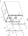
- FIG. 9 is a partially disassembled view of an embodiment of an electronic assembly including removable covers over the air inlets.
- A detailed description of one or more embodiments of the disclosed apparatus and method are presented herein by way of exemplification and not limitation with reference to the Figures.
- Referring to
FIGs 1-4 , illustrated is an embodiment of anelectronic assembly 110. Theelectronic assembly 110 includes anenclosure 112 and one or moreelectronic components 114 contained inside of theenclosure 112, and secured to a printedcircuit board 170 as shown in the cross-sectional view ofFIG. 2 . Theenclosure 112 includes a verticallytop surface 116 and a verticallybottom surface 118, with a plurality ofside portions 120 extending between the verticallytop surface 116 and the verticallybottom surface 118 to define theenclosure 112. Theenclosure 112 may be formed from, for example a metal material or a polymer material, or in some embodiments a combination thereof. - Referring to the partial cross-section of
FIG. 4 , anairflow 122 through one ormore cooling pathways 124 inside theenclosure 112 is utilized to remove thermal energy from the one or more electronic components 114 (shown inFIG. 2 ) disposed in theenclosure 112. Theairflow 122 is admitted to theenclosure 112 via one ormore airflow inlets 126 and flows through thecooling pathways 124, and exits theenclosure 112 via one ormore airflow outlets 128. In some embodiments, a fan (not shown) is utilized to urge theairflow 122 through theenclosure 112. - As shown best in
FIG. 3 , theairflow inlets 126 are positioned and configured to prevent direct impingement of debris such as sand, dust, water or the like into theairflow inlets 126. In particular, theairflow inlets 126 are located at the one ormore side portions 120 of theenclosure 112. The one ormore airflow inlets 126 face downward, meaning that theairflow 122 entering theairflow inlets 126 travels in a generally upward direction away from thebottom surface 118 and toward thetop surface 116 when theairflow 122 enters theairflow inlets 126. In some embodiments, theairflow inlets 126 are defined in aninlet duct 132 protruding from theside portion 120. Theairflow inlets 126 defined in theinlet duct 132 face toward thebottom surface 118. While in the embodiment ofFIG. 3 , theairflow inlets 126 are illustrated at oneside portion 120 of theenclosure 112, one skilled in the art will readily appreciate that in otherembodiments airflow inlets 126 may be positioned at two ormore side portions 120 in order to provide a selected amount ofairflow 122 to the interior of theenclosure 112 to remove thermal energy from the electronic components 114 (shown inFIG. 2 ) in theenclosure 112. Further, while theairflow inlets 126 illustrated inFIG. 3 are rectangular in shape, in other embodiments, theairflow inlets 126 may be, for example, circular, oval, or other geometric shape. A grate or screen (not shown) may be positioned at theairflow inlet 126 to aid in preventing the entry of debris into the interior of theenclosure 112. In addition to preventing impingement of debris into theairflow inlets 126, the downward facingairflow inlet 126 provides a drainage path out of theenclosure 112 for any water or other debris that may enter the cooling pathways ofenclosure 112. Additionally the downward facingairflow inlet 126 eliminates the need for additional protection of the cooling pathways 124 (shown inFIG. 2 ), via filters or the like, thus reducing cost and weight and improving cooling performance. - Referring now to
FIG. 5 , illustrated is anexemplary airflow outlet 228 of theenclosure 212. Theairflow outlet 228 is located at aside portion 220 of theenclosure 212. Theairflow outlet 228 is positioned and configured to face downward toward thebottom surface 218 of theenclosure 212, such that theexhaust airflow 262 leaving theenclosure 212 via theairflow outlet 228 proceeds downwardly out of theairflow outlet 228 in a direction away from thetop surface 216 and toward thebottom surface 218. - Referring to the cross-sectional view of
FIG. 6 , theairflow outlet 228 is positioned in anoutlet body 234 protruding from theside portion 220. Theoutlet body 234 includes abody housing 236 that defines anoutlet plenum 238 unto which theexhaust airflow 262 from the cooling pathways 224 is received. Afan cavity 240 is connected to theoutlet plenum 238 and thefan 230 is positioned in thefan cavity 240. Thefan 230 rotates about a fan axis 242, which in some embodiments is positioned perpendicular to a planar outlet opening 244 of theairflow outlet 228. A grate orscreen 260 may be positioned at theairflow outlet 228 to aid in preventing the entry of debris into the interior of theenclosure 212. Additionally the downward facingairflow outlet 228 eliminates the need for additional protection of the cooling pathways 224, via filters or the like, thus reducing cost and weight and improving cooling performance. In addition to preventing impingement of debris into theairflow outlets 228, the downward facingairflow outlet 228 provides a drainage path out of theenclosure 212 for any water or other debris that may enter theenclosure 212. - In another embodiment, illustrated in
FIG. 7-9 , theairflow inlets 326 are located on theside portion 320 and face outwardly from theside portion 320. One or moreremovable covers 346 are positioned outwardly from theairflow inlets 326. Thecovers 346 include anattachment portion 348 at which thecovers 346 are secured to theside portion 320 by, for example, one ormore screws 350. Acover portion 352 extends from theattachment portion 348. Thecover portion 352 is configured to be spaced apart from theairflow inlet 326 by, for example 1 millimeter to 5 millimeters, when thecover 346 is installed to theside portion 320. In some embodiments acover bend 354 defines the spacing between theairflow inlet 326 and thecover portion 352. When installed, thecover 346 prevents direct impingement of debris onto or into theairflow inlet 326. Additionally thecovers 346 eliminates the need for additional protection of the cooling pathways 24 (shown inFIG. 2 ), via filters or the like, thus reducing cost and weight and improving cooling performance. In addition, thecovers 346 are readily removable for use of theelectronic assembly 310 in applications wheresuch covers 346 may not be needed. - The term "about" is intended to include the degree of error associated with measurement of the particular quantity based upon the equipment available at the time of filing the application.
- The terminology used herein is for the purpose of describing particular embodiments only and is not intended to be limiting of the present disclosure. As used herein, the singular forms "a", "an" and "the" are intended to include the plural forms as well, unless the context clearly indicates otherwise. It will be further understood that the terms "comprises" and/or "comprising," when used in this specification, specify the presence of stated features, integers, steps, operations, elements, and/or components, but do not preclude the presence or addition of one or more other features, integers, steps, operations, element components, and/or groups thereof.
- While the present disclosure has been described with reference to an exemplary embodiment or embodiments, it will be understood by those skilled in the art that various changes may be made and equivalents may be substituted for elements thereof without departing from the scope of the present disclosure. In addition, many modifications may be made to adapt a particular situation or material to the teachings of the present disclosure without departing from the essential scope thereof. Therefore, it is intended that the present disclosure not be limited to the particular embodiment disclosed as the best mode contemplated for carrying out this present disclosure, but that the present disclosure will include all embodiments falling within the scope of the claims.
Claims (10)
- An electronic enclosure (112), comprising:a vertically top surface (116);a vertically bottom surface (118);a plurality of side portions (120) extending between the top surface and the bottom surface; anda cooling airflow inlet (126) to admit a cooling airflow into the enclosure;a cooling airflow outlet (128) to exhaust the cooling airflow from the enclosure; andwherein the cooling airflow inlet is downward facing toward the vertically bottom surface such that the cooling airflow flows into the cooling airflow inlet an upward direction toward the vertically top surface.
- The electronic enclosure of claim 1, wherein the cooling airflow inlet (126) is disposed at a side portion of the plurality of side portions (120).
- The electronic enclosure of claim 2, further comprising an inlet duct (132) protruding from a side portion of the plurality of side portions (120).
- The electronic enclosure of claim 3, wherein the cooling airflow inlet (126) is defined in the inlet duct (132).
- The electronic enclosure of any preceding claim, wherein the cooling airflow inlet (126) is one or more of rectangular, circular, oval, or other geometric shape.
- The electronic enclosure of any preceding claim, wherein the cooling airflow outlet (128) is downward facing toward the vertically bottom surface (118) such that the cooling airflow flows out of the cooling airflow outlet a downward direction toward the vertically bottom surface.
- The electronic enclosure of any preceding claim, further comprising a fan (230) disposed at the cooling airflow outlet (228) to urge the airflow through the cooling arrangement.
- The electronic enclosure of claim 7, further comprising an outlet plenum (238) disposed at the cooling airflow outlet upstream of the fan.
- The electronic enclosure of any preceding claim, wherein the cooling airflow inlet (126) is configured as a drainage path for the electronic assembly.
- An electronic assembly (110, 210. 310), comprising:one or more electronic components (114);the electronic enclosure of any preceding claim in which the one or more electronic components are disposed, the enclosure including:a cooling arrangement for thermal management of the one or more electronic components, the cooling arrangement including:the cooling airflow inlet (126);the cooling airflow outlet (128); andone or more cooling pathways (124) between the cooling airflow inlet and the cooling airflow outlet.
Applications Claiming Priority (1)
| Application Number | Priority Date | Filing Date | Title |
|---|---|---|---|
| US17/821,540 US20240074088A1 (en) | 2022-08-23 | 2022-08-23 | Debris-resistant cooling path |
Publications (1)
| Publication Number | Publication Date |
|---|---|
| EP4329441A1 true EP4329441A1 (en) | 2024-02-28 |
Family
ID=87695815
Family Applications (1)
| Application Number | Title | Priority Date | Filing Date |
|---|---|---|---|
| EP23192029.9A Pending EP4329441A1 (en) | 2022-08-23 | 2023-08-17 | Debris-resistant cooling path |
Country Status (2)
| Country | Link |
|---|---|
| US (1) | US20240074088A1 (en) |
| EP (1) | EP4329441A1 (en) |
Citations (2)
| Publication number | Priority date | Publication date | Assignee | Title |
|---|---|---|---|---|
| US20060243423A1 (en) * | 2005-05-02 | 2006-11-02 | Tellabs Operations, Inc. | Compact heat exchanger and method |
| US20200206694A1 (en) * | 2018-12-31 | 2020-07-02 | Ice Qube, Inc. | Filtered fan apparatus |
Family Cites Families (11)
| Publication number | Priority date | Publication date | Assignee | Title |
|---|---|---|---|---|
| US7312993B2 (en) * | 2005-12-22 | 2007-12-25 | Alcatel Lucent | Electronics equipment cabinet |
| US7532471B2 (en) * | 2007-05-01 | 2009-05-12 | Enermax Technology Corporation | Fan fastening structure for computer housing |
| EP2879476B1 (en) * | 2013-11-29 | 2016-06-29 | ABB Technology Oy | Electric apparatus |
| US20150241069A1 (en) * | 2014-02-27 | 2015-08-27 | Electrolux Home Products, Inc. | Wall oven cooling system |
| US10212861B2 (en) * | 2017-02-24 | 2019-02-19 | Halliburton Energy Services, Inc. | Variable frequency drive cabinet ventilation system, apparatus and method |
| US11191191B2 (en) * | 2017-12-11 | 2021-11-30 | Schlumberger Technology Corporation | Air cooled variable-frequency drive |
| US10548238B1 (en) * | 2018-12-13 | 2020-01-28 | Caterpillar Inc. | Duct design for airflow cooling systems |
| US11464133B2 (en) * | 2019-01-14 | 2022-10-04 | Hewlett Packard Enterprise Development Lp | Cooling container |
| WO2021234422A1 (en) * | 2020-05-22 | 2021-11-25 | Edge Mobility Ltd | Battery pack |
| US11466863B2 (en) * | 2020-09-14 | 2022-10-11 | Electrolux Home Products, Inc. | Ventilation system for a cooking appliance |
| US12592431B2 (en) * | 2021-11-23 | 2026-03-31 | Milwaukee Electric Tool Corporation | Portable power supply |
-
2022
- 2022-08-23 US US17/821,540 patent/US20240074088A1/en not_active Abandoned
-
2023
- 2023-08-17 EP EP23192029.9A patent/EP4329441A1/en active Pending
Patent Citations (2)
| Publication number | Priority date | Publication date | Assignee | Title |
|---|---|---|---|---|
| US20060243423A1 (en) * | 2005-05-02 | 2006-11-02 | Tellabs Operations, Inc. | Compact heat exchanger and method |
| US20200206694A1 (en) * | 2018-12-31 | 2020-07-02 | Ice Qube, Inc. | Filtered fan apparatus |
Also Published As
| Publication number | Publication date |
|---|---|
| US20240074088A1 (en) | 2024-02-29 |
Similar Documents
| Publication | Publication Date | Title |
|---|---|---|
| US6343984B1 (en) | Laminar flow duct cooling system | |
| US6101090A (en) | Electronic apparatus having an environmentally sealed external enclosure | |
| CN101669411B (en) | A system for recirculation of air in a component of a wind turbine | |
| US20120327601A1 (en) | Water-proof cover for an inverter unit | |
| US20050122682A1 (en) | Electronics arrangement | |
| US9392722B2 (en) | Cable backplane assembly and method | |
| US20080273304A1 (en) | Fan fastening structure for computer housing | |
| KR100572850B1 (en) | Enclosure structure of turbo blower | |
| JP3101746B2 (en) | Semiconductor cooling device | |
| JPH0385797A (en) | Cooling device for electric equipment | |
| EP4329440A1 (en) | Debris-resistant cooling path | |
| EP4333570A1 (en) | Debris-resistant cooling path | |
| US20240074088A1 (en) | Debris-resistant cooling path | |
| US12396135B2 (en) | Cooling device for electronic equipment | |
| JP4896359B2 (en) | Electronic equipment | |
| EP1755124A2 (en) | Electronic cooling apparatus | |
| EP4369149A2 (en) | Cooling device for electronic equipment | |
| JP2000065385A (en) | Ceiling-mounted air conditioner | |
| EP0914030A1 (en) | Enclosure for equipment which requires cooling | |
| CN213020027U (en) | Devices for heat dissipation of electronic components, outdoor units | |
| JP5003772B2 (en) | Air duct and electronic device | |
| JP3808018B2 (en) | Electronics | |
| JP6610280B2 (en) | Electronics | |
| CN206159076U (en) | Fan module and driver | |
| CN223583777U (en) | Relay protection device |
Legal Events
| Date | Code | Title | Description |
|---|---|---|---|
| PUAI | Public reference made under article 153(3) epc to a published international application that has entered the european phase |
Free format text: ORIGINAL CODE: 0009012 |
|
| STAA | Information on the status of an ep patent application or granted ep patent |
Free format text: STATUS: THE APPLICATION HAS BEEN PUBLISHED |
|
| AK | Designated contracting states |
Kind code of ref document: A1 Designated state(s): AL AT BE BG CH CY CZ DE DK EE ES FI FR GB GR HR HU IE IS IT LI LT LU LV MC ME MK MT NL NO PL PT RO RS SE SI SK SM TR |
|
| STAA | Information on the status of an ep patent application or granted ep patent |
Free format text: STATUS: REQUEST FOR EXAMINATION WAS MADE |
|
| 17P | Request for examination filed |
Effective date: 20240827 |
|
| RBV | Designated contracting states (corrected) |
Designated state(s): AL AT BE BG CH CY CZ DE DK EE ES FI FR GB GR HR HU IE IS IT LI LT LU LV MC ME MK MT NL NO PL PT RO RS SE SI SK SM TR |