EP4329428A1 - Induction heating with reduced magnetic fields - Google Patents
Induction heating with reduced magnetic fields Download PDFInfo
- Publication number
- EP4329428A1 EP4329428A1 EP23193581.8A EP23193581A EP4329428A1 EP 4329428 A1 EP4329428 A1 EP 4329428A1 EP 23193581 A EP23193581 A EP 23193581A EP 4329428 A1 EP4329428 A1 EP 4329428A1
- Authority
- EP
- European Patent Office
- Prior art keywords
- induction heating
- heating circuit
- susceptor
- circuit
- shielding
- Prior art date
- Legal status (The legal status is an assumption and is not a legal conclusion. Google has not performed a legal analysis and makes no representation as to the accuracy of the status listed.)
- Pending
Links
- 230000006698 induction Effects 0.000 title claims abstract description 490
- 238000010438 heat treatment Methods 0.000 title claims abstract description 487
- 230000005291 magnetic effect Effects 0.000 title claims abstract description 143
- 239000004020 conductor Substances 0.000 claims abstract description 122
- 238000000034 method Methods 0.000 claims abstract description 51
- 230000009467 reduction Effects 0.000 claims abstract description 50
- 229910052751 metal Inorganic materials 0.000 claims description 60
- 239000002184 metal Substances 0.000 claims description 60
- 239000011888 foil Substances 0.000 claims description 26
- 230000000903 blocking effect Effects 0.000 claims description 24
- WYTGDNHDOZPMIW-RCBQFDQVSA-N alstonine Natural products C1=CC2=C3C=CC=CC3=NC2=C2N1C[C@H]1[C@H](C)OC=C(C(=O)OC)[C@H]1C2 WYTGDNHDOZPMIW-RCBQFDQVSA-N 0.000 claims description 11
- RYGMFSIKBFXOCR-UHFFFAOYSA-N Copper Chemical compound [Cu] RYGMFSIKBFXOCR-UHFFFAOYSA-N 0.000 claims description 6
- 229910052802 copper Inorganic materials 0.000 claims description 6
- 239000010949 copper Substances 0.000 claims description 6
- 229910052782 aluminium Inorganic materials 0.000 claims description 5
- XAGFODPZIPBFFR-UHFFFAOYSA-N aluminium Chemical compound [Al] XAGFODPZIPBFFR-UHFFFAOYSA-N 0.000 claims description 5
- 238000004519 manufacturing process Methods 0.000 description 27
- 239000000463 material Substances 0.000 description 12
- 239000002131 composite material Substances 0.000 description 7
- 238000010586 diagram Methods 0.000 description 7
- 238000009954 braiding Methods 0.000 description 4
- 238000012423 maintenance Methods 0.000 description 4
- 230000033228 biological regulation Effects 0.000 description 3
- 230000005294 ferromagnetic effect Effects 0.000 description 3
- 230000001105 regulatory effect Effects 0.000 description 3
- 230000004044 response Effects 0.000 description 3
- 239000003381 stabilizer Substances 0.000 description 3
- XEEYBQQBJWHFJM-UHFFFAOYSA-N Iron Chemical compound [Fe] XEEYBQQBJWHFJM-UHFFFAOYSA-N 0.000 description 2
- PXHVJJICTQNCMI-UHFFFAOYSA-N Nickel Chemical compound [Ni] PXHVJJICTQNCMI-UHFFFAOYSA-N 0.000 description 2
- 230000005288 electromagnetic effect Effects 0.000 description 2
- 230000010354 integration Effects 0.000 description 2
- 239000000696 magnetic material Substances 0.000 description 2
- 230000008569 process Effects 0.000 description 2
- OKTJSMMVPCPJKN-UHFFFAOYSA-N Carbon Chemical compound [C] OKTJSMMVPCPJKN-UHFFFAOYSA-N 0.000 description 1
- 229920000049 Carbon (fiber) Polymers 0.000 description 1
- VYZAMTAEIAYCRO-UHFFFAOYSA-N Chromium Chemical compound [Cr] VYZAMTAEIAYCRO-UHFFFAOYSA-N 0.000 description 1
- ZOKXTWBITQBERF-UHFFFAOYSA-N Molybdenum Chemical compound [Mo] ZOKXTWBITQBERF-UHFFFAOYSA-N 0.000 description 1
- 239000000956 alloy Substances 0.000 description 1
- 229910045601 alloy Inorganic materials 0.000 description 1
- 230000008901 benefit Effects 0.000 description 1
- 239000004917 carbon fiber Substances 0.000 description 1
- 229910052804 chromium Inorganic materials 0.000 description 1
- 239000011651 chromium Substances 0.000 description 1
- 239000010941 cobalt Substances 0.000 description 1
- 229910017052 cobalt Inorganic materials 0.000 description 1
- GUTLYIVDDKVIGB-UHFFFAOYSA-N cobalt atom Chemical compound [Co] GUTLYIVDDKVIGB-UHFFFAOYSA-N 0.000 description 1
- 230000007613 environmental effect Effects 0.000 description 1
- 229910002804 graphite Inorganic materials 0.000 description 1
- 239000010439 graphite Substances 0.000 description 1
- 229910052742 iron Inorganic materials 0.000 description 1
- VNWKTOKETHGBQD-UHFFFAOYSA-N methane Chemical compound C VNWKTOKETHGBQD-UHFFFAOYSA-N 0.000 description 1
- 230000004048 modification Effects 0.000 description 1
- 238000012986 modification Methods 0.000 description 1
- 229910052750 molybdenum Inorganic materials 0.000 description 1
- 239000011733 molybdenum Substances 0.000 description 1
- 229910052759 nickel Inorganic materials 0.000 description 1
- 230000008520 organization Effects 0.000 description 1
- 230000035699 permeability Effects 0.000 description 1
- 229920000642 polymer Polymers 0.000 description 1
- 238000009419 refurbishment Methods 0.000 description 1
Images




Classifications
-
- H—ELECTRICITY
- H05—ELECTRIC TECHNIQUES NOT OTHERWISE PROVIDED FOR
- H05K—PRINTED CIRCUITS; CASINGS OR CONSTRUCTIONAL DETAILS OF ELECTRIC APPARATUS; MANUFACTURE OF ASSEMBLAGES OF ELECTRICAL COMPONENTS
- H05K9/00—Screening of apparatus or components against electric or magnetic fields
- H05K9/0073—Shielding materials
- H05K9/0075—Magnetic shielding materials
-
- H—ELECTRICITY
- H05—ELECTRIC TECHNIQUES NOT OTHERWISE PROVIDED FOR
- H05B—ELECTRIC HEATING; ELECTRIC LIGHT SOURCES NOT OTHERWISE PROVIDED FOR; CIRCUIT ARRANGEMENTS FOR ELECTRIC LIGHT SOURCES, IN GENERAL
- H05B6/00—Heating by electric, magnetic or electromagnetic fields
- H05B6/02—Induction heating
- H05B6/10—Induction heating apparatus, other than furnaces, for specific applications
- H05B6/105—Induction heating apparatus, other than furnaces, for specific applications using a susceptor
-
- H—ELECTRICITY
- H05—ELECTRIC TECHNIQUES NOT OTHERWISE PROVIDED FOR
- H05B—ELECTRIC HEATING; ELECTRIC LIGHT SOURCES NOT OTHERWISE PROVIDED FOR; CIRCUIT ARRANGEMENTS FOR ELECTRIC LIGHT SOURCES, IN GENERAL
- H05B6/00—Heating by electric, magnetic or electromagnetic fields
- H05B6/02—Induction heating
- H05B6/36—Coil arrangements
- H05B6/44—Coil arrangements having more than one coil or coil segment
-
- H—ELECTRICITY
- H05—ELECTRIC TECHNIQUES NOT OTHERWISE PROVIDED FOR
- H05K—PRINTED CIRCUITS; CASINGS OR CONSTRUCTIONAL DETAILS OF ELECTRIC APPARATUS; MANUFACTURE OF ASSEMBLAGES OF ELECTRICAL COMPONENTS
- H05K9/00—Screening of apparatus or components against electric or magnetic fields
- H05K9/0071—Active shielding
-
- H—ELECTRICITY
- H05—ELECTRIC TECHNIQUES NOT OTHERWISE PROVIDED FOR
- H05B—ELECTRIC HEATING; ELECTRIC LIGHT SOURCES NOT OTHERWISE PROVIDED FOR; CIRCUIT ARRANGEMENTS FOR ELECTRIC LIGHT SOURCES, IN GENERAL
- H05B2206/00—Aspects relating to heating by electric, magnetic, or electromagnetic fields covered by group H05B6/00
- H05B2206/02—Induction heating
- H05B2206/023—Induction heating using the curie point of the material in which heating current is being generated to control the heating temperature
Definitions
- the present disclosure relates generally to methods and equipment for out-of-autoclave curing of composite parts and deals more particularly with a method and equipment for induction heating with reduced magnetic fields outside of the induction heating circuit.
- the flow of alternating current through a conductor of the circuit results in a magnetic field.
- the susceptor and conductor are designed such that at temperatures below the Curie temperature of the susceptor, the magnetic field can be concentrated in the susceptor due to its magnetic permeability.
- the susceptor becomes non-ferromagnetic.
- the magnetic fields are no longer concentrated in the susceptor when the susceptor becomes non-ferromagnetic.
- Magnetic fields escape conventional induction heating circuits when the susceptors are near or reach a respective Curie temperature.
- FCC regulations include electromagnetic emission regulations.
- induction heating circuits are arranged in parallel circuit patterns to cancel long range electromagnetic effects from adjacent circuits to remain below FCC regulated limits of magnetic fields.
- lower frequency is used in induction heating circuits to remain below FCC regulated limits of magnetic fields.
- the present disclosure provides an induction heating system.
- the induction heating system comprises a conductor, a susceptor surrounding the conductor, and a magnetic field reduction.
- the susceptor has a Curie temperature.
- the magnetic field reduction is configured to reduce magnetic fields escaping the induction heating system, preferably when the susceptor is at the Curie temperature independent of a layout of the induction heating system within an induction heating device.
- the present disclosure also provides an induction heating circuit.
- the induction heating circuit comprises a conductor, a susceptor having a Curie temperature surrounding the conductor, and a shielding of conductive metal surrounding the susceptor and the conductor configured to reduce magnetic fields escaping the induction heating circuit, preferably when the susceptor is at the Curie temperature.
- the present disclosure provides an induction heating system.
- the induction heating system comprises a first induction heating circuit having a first current direction, and a second induction heating circuit twisted around the first induction heating circuit and a central axis.
- the second induction heating circuit has a second current direction opposite of the first current direction.
- the present disclosure provides a method of reducing magnetic fields escaping an induction heating system during induction heating.
- An induction heating circuit is surrounded with shielding.
- the induction heating circuit comprises a conductor and a susceptor surrounding the conductor.
- the susceptor has a Curie temperature, and the shielding is configured to reduce magnetic fields escaping the induction heating circuit, preferably when the susceptor is at the Curie temperature.
- the induction heating circuit is positioned into a layout in an induction heating device to form the induction heating system.
- the present disclosure provides a method of reducing magnetic fields escaping an induction heating system during induction heating.
- a first induction heating circuit and a second induction heating circuit are wrapped around a central axis to form a pair of induction heating circuits twisted around the central axis, the pair of induction heating circuits having opposite current directions.
- Power is applied to the first induction heating circuit and the second induction heating circuit.
- the magnetic fields from each of the first induction heating circuit and the second induction heating circuit are canceled out by the opposite current directions as power is applied to the first induction heating circuit and the second induction heating circuit.
- an induction heating system comprising a conductor, a susceptor surrounding the conductor, the susceptor having a Curie temperature; and magnetic field reduction configured to reduce magnetic fields escaping the induction heating system, preferably when the susceptor is at the Curie temperature independent of a layout of the induction heating system within an induction heating device.
- the magnetic field reduction can be shielding surrounding the susceptor.
- the shielding can comprise a spiral of conductive metal; a braid of conductive metal; and/or a foil of conductive metal.
- the shielding may comprise copper or aluminum.
- the magnetic field reduction may comprise a design of a pair of induction heating circuits twisted around a central axis, wherein the pair of induction heating circuits have opposite current directions, and wherein a first induction heating circuit of the pair of induction heating circuits comprises the conductor and the susceptor.
- the induction heating system comprises a bend such that the pair of induction heating circuits is formed of the conductor and the susceptor.
- the pair of induction heating circuits may further comprise a second induction heating circuit comprising a second conductor and a second susceptor.
- an induction heating circuit comprising a conductor, a susceptor having a Curie temperature surrounding the conductor; and a shielding of conductive metal surrounding the susceptor and the conductor configured to reduce magnetic fields escaping the induction heating circuit, preferably when the susceptor is at the Curie temperature.
- the shielding may comprise a spiral of conductive metal, a braid of conductive metal and/or a foil of conductive metal.
- the shielding may comprise copper or aluminum.
- an induction heating system comprising, a first induction heating circuit having a first current direction; and a second induction heating circuit twisted around the first induction heating circuit and a central axis, the second induction heating circuit having a second current direction opposite of the first current direction.
- the first induction heating circuit and the second induction heating circuit can be connected by a bend such that the first induction heating circuit and the second induction heating circuit are formed by a same conductor and a same susceptor surrounding the same conductor.
- the first induction heating circuit and the second induction heating circuit can be formed by separate lengths of conductor surrounded by susceptor, the first induction heating circuit and second induction heating circuit having separate electrical buses.
- the first induction heating circuit and the second induction heating circuit may each comprise shielding configured to reduce magnetic fields escaping a respective induction heating circuit, preferably when a respective susceptor is at a Curie temperature of the respective susceptor.
- Shielding for each of the first induction heating circuit and the second induction heating circuit may comprise conductive metal and is at least one of a braid, a foil, or a spiral.
- the first induction heating circuit and the second induction heating circuit can be a twisted pair of induction heating circuits, the induction heating system further comprising shielding surrounding the twisted pair of induction heating circuits, the shielding configured to reduce magnetic fields escaping the twisted pair of induction heating circuits, preferably when the twisted pair of induction heating circuits are at a Curie temperature of the twisted pair of induction heating circuits.
- a method of reducing magnetic fields escaping an induction heating system during induction heating comprising surrounding an induction heating circuit with shielding, the induction heating circuit comprising a conductor and a susceptor surrounding the conductor, the susceptor having a Curie temperature, and the shielding configured to reduce magnetic fields escaping the induction heating circuit, preferably when the susceptor is at the Curie temperature and positioning the induction heating circuit into a layout in an induction heating device to form the induction heating system.
- Surrounding the induction heating circuit with shielding may comprise wrapping the conductor and the susceptor in a spiral of conductive metal. Surrounding the induction heating circuit with shielding can comprise braiding a conductive metal around the conductor and the susceptor.
- Surrounding the induction heating circuit with shielding can comprise wrapping the conductor and the susceptor in a foil of conductive metal.
- Surrounding the induction heating circuit with shielding may comprise braiding a conductive metal around the conductor and the susceptor and wrapping the conductor and the susceptor in a foil of conductive metal.
- Positioning the induction heating circuit into a layout can comprise positioning the induction heating circuit into the layout that is non-serpentine.
- a method of reducing magnetic fields escaping an induction heating system during induction heating comprising, wrapping a first induction heating circuit and a second induction heating circuit around a central axis to form a pair of induction heating circuits twisted around the central axis, the pair of induction heating circuits having opposite current directions, applying power to the first induction heating circuit and the second induction heating circuit, and canceling out the magnetic fields from each of the first induction heating circuit and the second induction heating circuit by the opposite current directions as power is applied to the first induction heating circuit and the second induction heating circuit.
- the pair of induction heating circuits can be positioned into a layout to form the induction heating system in an induction heating device, wherein the opposite current directions cancel out the magnetic fields independent of the layout.
- the layout is preferably non-serpentine.
- the disclosure recognizes and take into account one or more different considerations.
- the disclosure recognizes and take into account that a composite part can be cured in an oven or an autoclave where heat is applied to the part while supported on a cure tool that maintains the shape of the part during the curing process.
- the disclosure recognizes and takes into account that curing the composite material using an autoclave may use at least one of undesirable amount of time or an undesirable amount of energy.
- the disclosure recognizes and takes into account that induction heating techniques have been developed for curing composite parts without the need for an oven or autoclave, however these techniques have been limited by the frequency of the induction current and the design of the induction tools.
- the disclosure recognizes and take into account that higher frequency power supplies generate higher currents which can generate high electromagnetic emissions.
- the disclosure recognizes and takes into account that electromagnetic noise could interfere with electronics.
- the disclosure also recognizes and takes into account that there are FCC regulations regarding electromagnetic emissions.
- the disclosure recognizes and takes into account that eddy currents can undesirably generate heat in surrounding materials.
- the disclosure recognizes and take into account that conventional induction heating circuits are arranged in parallel circuit patterns to cancel electromagnetic effect from adjacent circuits.
- the disclosure recognizes and takes into account that currently lower frequency is used in induction heating circuits to remain below FCC regulated limits of magnetic fields.
- the disclosure recognizes and takes into account that it may be desirable to utilize power supplies with higher frequencies without generating high electromagnetic emissions.
- the disclosure recognizes and takes into account that it would be desirable to have greater flexibility in the design of induction heating tools.
- the disclosure provides an induction heating system.
- the induction heating system comprises a conductor, a susceptor surrounding the conductor, and a magnetic field reduction.
- the susceptor has a Curie temperature.
- the magnetic field reduction is configured to reduce magnetic fields escaping the induction heating system, preferably when the susceptor is at the Curie temperature independent of a layout of the induction heating system within an induction heating device.
- the disclosure provides greater flexibility in the layout of induction heating circuits.
- the disclosure provides an induction heating system that generates lower electromagnetic emission.
- Aircraft 100 has wing 102 and wing 104 attached to body 106. Aircraft 100 includes engine 108 attached to wing 102 and engine 110 attached to wing 104.
- Body 106 has tail section 112. Horizontal stabilizer 114, horizontal stabilizer 116, and vertical stabilizer 118 are attached to tail section 112 of body 106.
- Aircraft 100 is an example of an aircraft having large composite components that can be manufactured using an induction heating system having magnetic field reduction. For example, portions of body 106, wing 102, or wing 104 can be manufactured using an induction heating system having magnetic field reduction.
- Manufacturing environment 200 is a manufacturing environment in which a component of aircraft 100 can be manufactured.
- a portion of body 106, wing 102, or wing 104 could be manufactured using induction heating device 202 in manufacturing environment 200.
- Induction heating device 202 can take the form of induction heating blanket 204 or rigid induction tooling 206.
- Induction heating device 202 comprises induction heating system 208 to provide heat in induction heating device 202.
- Induction heating system 208 comprises set of induction heating circuits 210 having layout 212 in induction heating device 202.
- a "set of" items is one or more items.
- set of induction heating circuits 210 is one or more induction heating circuits.
- Induction heating system 208 comprises conductor 214, susceptor 216 surrounding conductor 214, and magnetic field reduction 218.
- Susceptor 216 has Curie temperature 220.
- Magnetic field reduction 218 is configured to reduce magnetic fields 222 escaping induction heating system 208 when susceptor 216 is at, near or approaching Curie temperature 220 independent of layout 212 of induction heating system 208 within induction heating device 202.
- Magnetic field reduction 218 allows layout 212 of set of induction heating circuits 210 to deviate from conventional parallel designs without unacceptable emissions of magnetic fields 222. Magnetic field reduction 218 allows layout 212 of set of induction heating circuits 210 to be non-serpentine.
- Positioning set of induction heating circuits into layout 212 may comprise positioning a set of induction heating circuits into layout 212 that is non-serpentine. Magnetic field reduction 218 enables non-serpentine layouts of sets of induction heating circuits 210 without undesirable quantities of magnetic emissions.
- Susceptor 216 comprises a metal, an alloy, or any other suitable material that is electrically conducting and having Curie temperature 220 in a range for performing a desired operation on a material.
- Susceptor 216 may comprise at least one of iron, cobalt, nickel, molybdenum, or chromium.
- Power source 224 provides alternating current 226 to conductor 214.
- Conductor 214 receives alternating current 226 and generates magnetic fields 222 in response to alternating current 226.
- Conductor 214 comprises any desirable material having low electrical resistance.
- Conductor 214 may be formed of a flexible material to enable use of first induction heating circuit 231 in induction heating blanket 204.
- Conductor 214 may be formed of a flexible material to enable the use of conductor 214 in curved surfaces.
- Conductor 214 can comprise Litz wire 227.
- Susceptor 216 is a magnetic material located adjacent to conductor 214. The magnetic material generates heat in response to magnetic fields 222.
- Curie temperature 220 is a temperature at which susceptor 216 becomes non-ferromagnetic. The heating of susceptor 216 due to magnetic fields 222 ceases when susceptor 216 reaches, or is near, Curie temperature 220.
- Susceptor 216 may be referred to as a "smart susceptor”. Susceptor 216 extends along conductor 214. Susceptor 216 can be coaxially mounted to conductor 214 and electrically insulated from conductor 214 for induction heating in response to magnetic fields 222.
- the magnetic field reduction 218 may comprise shielding 228 surrounding susceptor 216. Shielding 228 blocks magnetic fields 222 from escaping first induction heating circuit 231. By blocking magnetic fields 222, shielding 228 reduces magnetic fields 222 escaping induction heating system 208. Shielding 228 is formed of conductive metal 230. Conductive metal 230 is selected based on at least one of conduction, cost, and manufacturability. Conductive metal 230 can be selected from copper or aluminum. Shielding 228 can comprise copper or aluminum. Shielding 228 can physically block magnetic fields 222 from exiting first induction heating circuit 231, preferably after susceptor 216 reaches Curie temperature 220. Shielding 228 may block magnetic fields 222 from exiting first induction heating circuit 231 using an induced current with an opposing field in shielding 228 preferably after susceptor 216 reaches Curie temperature 220.
- Slight heating can occur in shielding 228 when using an induced current to block magnetic fields 222.
- the low electrical resistance of conductive metal 230 of shielding 228 is selected to reduce heating occurring in shielding 228 when a current is applied.
- Shielding 228 may comprise a combination of physical blocking of magnetic fields 222 and current induced blocking of magnetic fields 222. Here the ratio and combination of physical blocking and current induced blocking is engineered based on the application.
- Shielding 228 can comprise spiral 232 of conductive metal 230.
- Shielding 228 can comprise foil 234 of conductive metal 230.
- Shielding 228 can comprise braid 236 of conductive metal 230.
- Magnetic field reduction 218 can comprise design 238 of pair of induction heating circuits 240 twisted 242 around central axis 244. Pair of induction heating circuits 240 have opposite current directions 246.
- First induction heating circuit 231 of pair of induction heating circuits 240 comprises conductor 214 and susceptor 216 and has first current direction 248.
- Second induction heating circuit 250 having second current direction 252 comprises susceptor 256 and conductor 254.
- Induction heating system 208 may comprise first induction heating circuit 231 having first current direction 248 and a second induction heating circuit 250 twisted 242 around first induction heating circuit 231 and central axis 244, the second induction heating circuit 250 having a second current direction 252.
- the twisted 242 pair of induction heating circuits 240 can generate a higher magnetic field (B) intensity.
- the space between the wires may have 2xB.
- Higher magnetic field intensity will increase Curie temperature 220 drop-off and improve 'smartness' of twisted 242 pair of induction heating circuits 240.
- Design 238 of twisted 242 pair of induction heating circuits 240 provides cancellation of magnetic fields 222.
- Field intensity between first induction heating circuit 231 and second induction heating circuit 250 increases, but the direction changes as each of the induction heating circuits twist.
- the sum of magnetic fields for first induction heating circuit 231 and second induction heating circuit 250 can be closer to zero than conventional parallel wire designs.
- the first induction heating circuit 231 and second induction heating circuit 250 are preferably connected by bend 258 such that first induction heating circuit 231 and second induction heating circuit 250 are formed by a same conductor and a same susceptor surrounding the conductor.
- the susceptor 216 and susceptor 256 are formed of a single length of susceptor.
- the induction heating system 208 may comprise a bend such that pair of induction heating circuits 240 is formed of conductor 214 and susceptor 216.
- the pair of induction heating circuits 240 may comprise second induction heating circuit 250 comprising a second conductor, conductor 254, and a second susceptor, susceptor 256.
- second induction heating circuit 250 comprising a second conductor, conductor 254, and a second susceptor, susceptor 256.
- a first induction heating circuit 231 and second induction heating circuit 250 have independent lengths of susceptor and independent lengths of conductor.
- First induction heating circuit 231 may comprise conductor 214; susceptor 216 having Curie temperature 220 surrounding conductor 214; and shielding 228 of conductive metal 230 surrounding susceptor 216 and conductor 214. Shielding 228 is configured to reduce magnetic fields 222 escaping first induction heating circuit 231 when susceptor 216 is at, or near Curie temperature 220.
- First induction heating circuit 231 and second induction heating circuit 250 can be formed by separate lengths of conductor surrounded by susceptor, first induction heating circuit 231 and second induction heating circuit 250 having separate electrical buses.
- Susceptor 216 can be a separate length from susceptor 256.
- Conductor 214 can be a separate length from conductor 254.
- First induction heating circuit 231 and the second induction heating circuit may each comprise shielding 228 configured to reduce magnetic fields escaping a respective induction heating circuit, preferably when a respective susceptor is at a Curie temperature of the respective susceptor.
- Shielding 228 for each of first induction heating circuit 231 and second induction heating circuit 250 comprises conductive metal and is at least one of a braid, a foil, or a spiral.
- Magnetic field reduction 218 enables larger spacing between adjacent portions of set of induction heating circuits 210 without undesirable magnetic emissions.
- Magnetic field reduction 218 enables layout 212 that is non-serpentine without undesirable magnetic emissions.
- Magnetic field reduction 218 also enables larger diameter set of induction heating circuits 210 without undesirable magnetic emissions.
- Magnetic field reduction 218 enables use of higher frequency power source 224 without undesirable magnetic emissions.
- Use of larger diameter set of induction heating circuits 210 with greater spacing in layout 212 can reduce manufacturing difficulty and manufacturing costs of rigid induction tool 206.
- Set of induction heating circuits 210 are placed into milled grooves in rigid induction tool 206. Reducing the quantity of the milled grooves reduces at least one of manufacturing difficulty or manufacturing costs of rigid induction tool 206. Reducing the difficulty of the layout of the milled grooves reduces at least one of manufacturing difficulty or manufacturing costs of rigid induction tool 206.
- induction heating device 202 in Figure 2 is not meant to imply physical or architectural limitations to the manner in which the disclosure may be implemented. Other components in addition to or in place of the ones illustrated may be used. Some components may be unnecessary. Also, the blocks are presented to illustrate some functional components. One or more of these blocks may be combined, divided, or combined and divided into different blocks when implemented in the present disclosure. For example, thermal sensors can be present in induction heating device 202. As another example, second induction heating circuit 250 may be optional.
- shielding 228 is depicted as associated with first induction heating circuit 231, shielding 228 can be associated with any desirable induction heating circuits in set of induction heating circuits 210.
- Each of first induction heating circuit 231 and second induction heating circuit 250 can have separate shielding 228.
- first induction heating circuit 231 can have shielding 228 around conductor 214 and susceptor 216 while second induction heating circuit 250 has a separate length of shielding 228 around susceptor 256 and conductor 254.
- Shielding 228 can wrap around both first induction heating circuit 231 and second induction heating circuit 250 such that shielding 228 encompasses susceptor 216, conductor 214, susceptor 256, and conductor 254.
- shielding 228 When shielding 228 encircles both first induction heating circuit 231 and second induction heating circuit 250, shielding 228 may be referred to as "shared shielding" for first induction heating circuit 231 and second induction heating circuit 250.
- a diameter of shielding 228 that is shared by both first induction heating circuit 231 and second induction heating circuit 250 is greater than a diameter of shielding 228 that encircles first induction heating circuit 231 and second induction heating circuit 250 individually.
- First induction heating circuit 231 and second induction heating circuit 250 can be a twisted 242 pair of induction heating circuits 240.
- Shielding 228 can surround twisted 242 pair of induction heating circuits 240, shielding 228 configured to reduce magnetic fields 222 escaping twisted 242 pair of induction heating circuits 240, preferably when twisted 242 pair of induction heating circuits 240 is at Curie temperature 220 of twisted 242 pair of induction heating circuits 240.
- Induction heating circuit 300 is a physical implementation of first induction heating circuit 231 of Figure 2 .
- Induction heating circuit 300 comprises conductor 302, susceptor 304, and magnetic field reduction 306.
- Susceptor 304 surrounds conductor 302.
- Susceptor 304 is coaxial with conductor 302.
- susceptor 304 is depicted as a sleeve, susceptor 304 can take any desirable form.
- Susceptor 304 may take the form of a spiral, a coil, multiple short sleeves, or any other desirable form to surround conductor 302.
- Magnetic field reduction 306 can be configured to reduce magnetic fields escaping induction heating circuit 300 when susceptor 304 is at, or near, the Curie temperature independent of a layout of an induction heating system having induction heating circuit 300.
- Magnetic field reduction 306 takes the form of shielding 308.
- Shielding 308 surrounds susceptor 304.
- Shielding 308 is a conductive metal and is one of a spiral, a braid, or a foil. Shielding 308 blocks magnetic fields from exiting induction heating circuit 300, preferably after susceptor 304 reaches its Curie temperature through at least one of physically blocking or blocking the magnetic fields using induced currents.
- Induction heating circuit 400 is a physical implementation of first induction heating circuit 231 of Figure 2 .
- Induction heating circuit 400 comprises conductor 402, susceptor 404, and magnetic field reduction 406.
- Susceptor 404 surrounds conductor 402.
- Susceptor 404 is coaxial with conductor 402.
- susceptor 404 is depicted as a sleeve, susceptor 404 can take any desirable form.
- Susceptor 404 may take the form of a spiral, a coil, multiple short sleeves, or any other desirable form to surround conductor 402.
- Magnetic field reduction 406 takes the form of shielding 408.
- Shielding 408 surrounds susceptor 404.
- Shielding 408 can comprise first layer 410 and second layer 412.
- First layer 410 and second layer 412 comprise two different types of shielding of conductive metal selected from a spiral, a foil, and a braid.
- Shielding 408 blocks magnetic fields from exiting induction heating circuit 400, preferably after susceptor 404 reaches its Curie temperature through at least one of physically blocking or blocking the magnetic fields using induced currents.
- Induction heating circuit 500 is physical implementation of first induction heating circuit 231 of Figure 2 .
- Induction heating circuit 500 is a physical implementation of induction heating circuit 300 of Figure 3 .
- Induction heating circuit 500 comprises conductor 502, susceptor 504, and magnetic field reduction 506.
- Susceptor 504 surrounds conductor 502.
- Susceptor 504 is coaxial with conductor 502.
- susceptor 504 is depicted as a sleeve, susceptor 504 can take any desirable form.
- Susceptor 504 takes the form of a spiral, a coil, multiple short sleeves, or any other desirable form to surround conductor 502.
- Magnetic field reduction 506 takes the form of shielding 508.
- Shielding 508 surrounds susceptor 504.
- Shielding 508 can comprise spiral 510 formed of a conductive metal.
- Exterior 512 provides an optional layer of polymeric material. Exterior 512 can be provided for easier handling.
- FIG 6 an illustration of a partially exploded view of an induction heating circuit with foil shielding is depicted in accordance with the disclosure.
- Induction heating circuit 600 is physical implementation of first induction heating circuit 231 of Figure 2 .
- Induction heating circuit 600 is a physical implementation of induction heating circuit 300 of Figure 3 .
- Induction heating circuit 600 comprises conductor 602, susceptor 604, and magnetic field reduction 606.
- Susceptor 604 surrounds conductor 602.
- Susceptor 604 is coaxial with conductor 602.
- susceptor 604 is depicted as a sleeve, susceptor 604 can take any desirable form.
- Susceptor 604 takes the form of a spiral, a coil, multiple short sleeves, or any other desirable form to surround conductor 602.
- Magnetic field reduction 606 takes the form of shielding 608.
- Shielding 608 surrounds susceptor 604.
- Shielding 608 can comprise foil 610 formed of a conductive metal.
- Exterior 612 provides an optional layer of polymeric material. Exterior 612 can be provided for easier handling.
- Induction heating circuit 700 is physical implementation of first induction heating circuit 231 of Figure 2 .
- Induction heating circuit 700 is a physical implementation of induction heating circuit 300 of Figure 3 .
- Induction heating circuit 700 comprises conductor 702, susceptor 704, and magnetic field reduction 706.
- Susceptor 704 surrounds conductor 702.
- Susceptor 704 is coaxial with conductor 702.
- susceptor 704 is depicted as a sleeve, susceptor 704 can take any desirable form.
- Susceptor 704 may take the form of a spiral, a coil, multiple short sleeves, or any other desirable form to surround conductor 702.
- Magnetic field reduction 706 takes the form of shielding 708.
- Shielding 708 surrounds susceptor 704.
- Shielding 708 can comprise braid 710 formed of a conductive metal.
- Exterior 712 provides an optional layer of polymeric material. Exterior 712 can be provided for easier handling.
- Induction heating circuit 800 is physical implementation of first induction heating circuit 231 of Figure 2 .
- Induction heating circuit 800 is a physical implementation of induction heating circuit 300 of Figure 3 .
- Induction heating circuit 800 comprises conductor 802, susceptor 804, and magnetic field reduction 806.
- Susceptor 804 surrounds conductor 802.
- Susceptor 804 is coaxial with conductor 802.
- susceptor 804 is depicted as a sleeve, susceptor 804 can take any desirable form.
- Susceptor 804 may take the form of a spiral, a coil, multiple short sleeves, or any other desirable form to surround conductor 802.
- Magnetic field reduction 806 takes the form of shielding 808.
- Shielding 808 surrounds susceptor 804.
- Shielding 808 can comprise first layer 810 and second layer 812.
- First layer 810 and second layer 812 comprise two different types of shielding of conductive metal selected from a spiral, a foil, and a braid.
- First layer 810 may comprise a braid of conductive metal and second layer 812 comprises a foil of conductive metal.
- first layer 810 comprises a foil of conductive metal and second layer 812 comprises a braid of conductive metal.
- Exterior 814 provides an optional layer of polymeric material. Exterior 814 can be provided for easier handling.
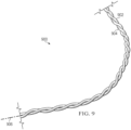
- Induction heating system 900 can be a physical implementation of induction heating system 208 of Figure 2 .
- Induction heating system 900 comprises first induction heating circuit 902 having a first current direction and second induction heating circuit 904 twisted around first induction heating circuit 902 and central axis 906.
- Second induction heating circuit 904 having a second current direction opposite from the first current direction.
- First induction heating circuit 902 and second induction heating circuit 904 can be connected by a bend (not depicted) such that first induction heating circuit 902 and second induction heating circuit 904 are formed by a same conductor and a same susceptor surrounding the conductor.
- First induction heating circuit 902 and second induction heating circuit 904 can be formed by separate lengths of conductor surrounded by susceptor.
- First induction heating circuit 902 and second induction heating circuit 904 can have separate electrical buses.
- the magnetic field reduction for induction heating system 900 can be provided by electromagnetic cancellation of the opposite currents.
- the magnetic field reduction for induction heating system 900 can be provided by both electromagnetic cancellation and shielding.
- First induction heating circuit 902 and second induction heating circuit 904 may each comprise shielding configured to reduce magnetic fields escaping a respective induction heating circuit, preferably when a respective susceptor is at, or near, a Curie temperature of the respective susceptor.
- the shielding (not depicted) can be one length and wraps around itself in induction heating system 900 due to twisting of first induction heating circuit 902 and second induction heating circuit 904.
- the shielding for first induction heating circuit 902 and second induction heating circuit 904 can be two separate lengths of shielding.
- the shielding for each of the first induction heating circuit and the second induction heating circuit may comprise conductive metal and is at least one of a braid, a foil, or a spiral. Shielding is not necessarily present in induction heating system 900. Shielding can be present around only one of first induction heating circuit 902 or second induction heating circuit 904.
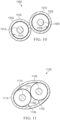
- Induction heating system 1000 is a physical implementation of induction heating system 208 of Figure 2 .
- Induction heating system 1000 may be an implementation of induction heating system 900 with shielding around each induction heating circuit.
- Induction heating system 1000 comprises pair of induction heating circuits 1001.
- Induction heating system 1000 comprises first induction heating circuit 1002 having a first current direction, and second induction heating circuit 1004 twisted around first induction heating circuit 1002 and central axis 1005.
- Second induction heating circuit 1004 has a second current direction opposite from the first current direction.
- Magnetic field reduction may comprise the design of pair of induction heating circuits 1001 twisted around central axis 1005. Pair of induction heating circuits 1001 have opposite current directions. The opposite current directions create cancellation of magnetic fields, preferably when susceptor 1008 and susceptor 1014 reach their Curie temperature. The opposite current directions of first induction heating circuit 1002 and second induction heating circuit 1004 cancel out each other's magnetic fields.
- First induction heating circuit 1002 of pair of induction heating circuits 1001 comprises conductor 1006 and susceptor 1008.
- Induction heating system 1000 can comprise a bend (not depicted) such that pair of induction heating circuits 1001 is formed of one length of conductor and susceptor. Conductor 1006 and conductor 1012 can be formed of a single length of conductive metal.
- Susceptor 1008 and susceptor 1014 can be formed of a single length of susceptor.
- Pair of induction heating circuits 1001 may comprise second induction heating circuit 1004 comprising a second conductor and a second susceptor.
- Conductor 1006 and conductor 1012 can be formed of separate lengths of conductive material.
- Susceptor 1008 and susceptor 1014 can be formed of separate lengths of susceptor.
- First induction heating circuit 1002 and second induction heating circuit 1004 can utilize two separate electrical buses.
- Magnetic field reduction may further comprise shielding 1010 surrounding susceptor 1008. Shielding 1010 blocks magnetic fields from escaping first induction heating circuit 1002. By blocking magnetic fields, shielding 1010 reduces magnetic fields escaping induction heating system 1000. Magnetic field reduction may further comprises shielding 1016 surrounding susceptor 1014. Shielding 1016 blocks magnetic fields from escaping second induction heating circuit 1004. By blocking magnetic fields, shielding 1016 reduces magnetic fields escaping induction heating system 1000. Shielding 1010 and shielding 1016 are formed of conductive metal. At least one of shielding 1010 or shielding 1016 may comprise a spiral of conductive metal. At least one of shielding 1010 or shielding 1016 may comprise a foil of conductive metal.
- At least one of shielding 1010 or shielding 1016 may comprise braid of conductive metal.
- Shielding 1010 and shielding 1016 can be individual and separate lengths of shielding.
- Shielding 1010 and shielding 1016 can be connected by a bend and are part of a continuous length of shielding.
- Induction heating system 1100 is a physical implementation of induction heating system 208 of Figure 2 .
- Induction heating system 1100 can be an implementation of induction heating system 900 with shielding around both of the induction heating circuits.
- Induction heating system 1100 comprises pair of induction heating circuits 1101.
- Induction heating system 1100 comprises first induction heating circuit 1102 having a first current direction, and second induction heating circuit 1104 twisted around first induction heating circuit 1102 and central axis 1105.
- Second induction heating circuit 1104 has a second current direction opposite from the first current direction.
- Magnetic field reduction may comprise the design of pair of induction heating circuits 1101 twisted around central axis 1105. Pair of induction heating circuits 1101 have opposite current directions. The opposite current directions create cancellation of magnetic fields, preferably when susceptor 1108 and susceptor 1112 reach their Curie temperature. The opposite current directions of first induction heating circuit 1102 and second induction heating circuit 1104 cancel out each other's magnetic fields.
- First induction heating circuit 1102 of pair of induction heating circuits 1101 comprises conductor 1106 and susceptor 1108.
- Induction heating system 1100 may comprise a bend (not depicted) such that pair of induction heating circuits 1101 is formed of one length of conductor and susceptor.
- Conductor 1106 and conductor 1110 can be formed of a single length of conductive metal.
- Susceptor 1108 and susceptor 1112 can be formed of a single length of susceptor.
- Pair of induction heating circuits 1101 may comprise second induction heating circuit 1104 comprising a second conductor and a second susceptor.
- Conductor 1106 and conductor 1110 can be formed of separate lengths of conductive material.
- Susceptor 1108 and susceptor 1112 can be formed of separate lengths of susceptor.
- First induction heating circuit 1102 and second induction heating circuit 1104 may utilize two separate electrical buses.
- Magnetic field reduction may further comprise shielding 1114 surrounding susceptor 1108 and susceptor 1112. Shielding 1114 blocks magnetic fields from escaping first induction heating circuit 1102 and second induction heating circuit 1104. By blocking magnetic fields, shielding 1114 reduces magnetic fields escaping induction heating system 1100.
- Shielding 1114 is formed of conductive metal.
- Shielding 1114 may comprise at least one of a spiral of conductive metal, a foil of conductive metal, or a braid of conductive metal. In induction heating system 1100, shielding 1114 wraps around both first induction heating circuit 1102 and second induction heating circuit 1104. Shielding 1114 has a greater diameter than both shielding 1010 and shielding 1016 of Figure 10 that encompass individual induction heating circuits.
- induction heating system 1000 and induction heating system 1100 are depicted with shielding.
- an induction heating system such as induction heating system 900 of Figure 9 , with a twisted pair of induction circuits can be utilized without shielding.
- Method 1200 can be used to form induction heating system 208 of Figure 2 .
- Method 1200 can be used to form any of induction heating circuit 300 of Figure 3 , induction heating circuit 400 of Figure 4 , induction heating circuit 500 of Figure 5 , induction heating circuit 600 of Figure 6 , induction heating circuit 700 of Figure 7 , or induction heating circuit 800 of Figure 8 .
- Method 1200 surrounds an induction heating circuit with shielding, the induction heating circuit comprising a conductor and a susceptor surrounding the conductor, the susceptor having a Curie temperature, and the shielding configured to reduce magnetic fields escaping the induction heating circuit, preferably when the susceptor is at the Curie temperature (operation 1202).
- Method 1200 positions the induction heating circuit into a layout in an induction heating device to form the induction heating system (operation 1204). Afterwards, method 1200 terminates.
- Surrounding the induction heating circuit with shielding may comprise wrapping the conductor and the susceptor in a spiral of conductive metal (operation 1206).
- Surrounding the induction heating circuit with shielding may comprise braiding a conductive metal around the conductor and the susceptor (operation 1208).
- Surrounding the induction heating circuit with shielding may comprise wrapping the conductor and the susceptor in a foil of conductive metal (operation 1210). Surrounding the induction heating circuit with shielding may comprise braiding a conductive metal around the conductor and the susceptor and wrapping the conductor and the susceptor in a foil of conductive metal (operation 1212).
- Positioning the induction heating circuit into a layout may comprise positioning the induction heating circuit into the layout that is non-serpentine (operation 1214).
- the shielding enables non-serpentine layouts of the induction heating circuit without undesirable quantities of magnetic emissions.
- Method 1300 can be used to form induction heating system 208 of Figure 2 .
- Method 1300 can be used to form any of induction heating system 900 of Figure 9 , induction heating system 1000 of Figure 10 , or induction heating system 1100 of Figure 11 .
- Method 1300 wraps a first induction heating circuit and a second induction heating circuit around a central axis to form a pair of induction heating circuits twisted around the central axis, the pair of induction heating circuits having opposite current directions (operation 1302).
- Method 1300 applies power to the first induction heating circuit and the second induction heating circuit (operation 1304).
- Method 1300 cancels out the magnetic fields from each of the first induction heating circuit and the second induction heating circuit by the opposite current directions as power is applied to the first induction heating circuit and the second induction heating circuit (operation 1306). Afterwards, method 1300 terminates.
- Method 1300 may further comprise positioning the pair of induction heating circuits into a layout to form the induction heating system in an induction heating device, wherein the opposite current directions cancel out the magnetic fields independent of the layout (operation 1308).
- the layout can be non-serpentine (operation 1310).
- the phrase "at least one of,” when used with a list of items, means different combinations of one or more of the listed items may be used and only one of each item in the list may be needed.
- “at least one of item A, item B, or item C” may include, without limitation, item A, item A and item B, or item B. This example also may include item A, item B, and item C or item B and item C. Of course, any combinations of these items may be present.
- "at least one of” may be, for example, without limitation, two of item A; one of item B; and ten of item C; four of item B and seven of item C; or other suitable combinations.
- the item may be a particular object, thing, or a category.
- at least one of means any combination items and number of items may be used from the list but not all of the items in the list are required.
- the flowcharts and block diagrams in disclosure illustrate the architecture, functionality, and operation of possible implementations of apparatuses and methods.
- each block in the flowcharts or block diagrams may represent at least one of a module, a segment, a function, or a portion of an operation or step.
- aircraft manufacturing and service method 1400 may include specification and design 1402 of aircraft 1500 in Figure 15 and material procurement 1404.
- aircraft 1500 During production, component and subassembly manufacturing 1406 and system integration 1408 of aircraft 1500 takes place. Thereafter, aircraft 1500 may go through certification and delivery 1410 in order to be placed in service 1412. While in service 1412 by a customer, aircraft 1500 is scheduled for routine maintenance and service 1414, which may include modification, reconfiguration, refurbishment, or other maintenance and service.
- Each of the processes of aircraft manufacturing and service method 1400 may be performed or carried out by a system integrator, a third party, and/or an operator.
- the operator may be a customer.
- a system integrator may include, without limitation, any number of aircraft manufacturers and major-system subcontractors
- a third party may include, without limitation, any number of vendors, subcontractors, and suppliers
- an operator may be an airline, a leasing company, a military entity, a service organization, and so on.
- aircraft 1500 is produced by aircraft manufacturing and service method 1400 of Figure 14 and may include airframe 1502 with plurality of systems 1504 and interior 1506.
- systems 1504 include one or more of propulsion system 1508, electrical system 1510, hydraulic system 1512, and environmental system 1514. Any number of other systems may be included.
- Apparatuses and methods embodied herein may be employed during at least one of the stages of aircraft manufacturing and service method 1400.
- the present disclosure may be manufactured or used during at least one of component and subassembly manufacturing 1406, system integration 1408, in service 1412, or maintenance and service 1414 of Figure 14 .
- a portion of airframe 1502 of aircraft 1500 can be formed by an induction heating circuit formed by method 1200.
- a portion of airframe 1502 of aircraft 1500 can be formed by method 1300.
- An induction heating device formed by either method 1200 or method 1300 can be used during component and subassembly manufacturing 1406. Portions of method 1300 can be performed during component and subassembly manufacturing 1406.
- Induction heating device 202 can be used to form a composite structure during component and subassembly manufacturing 1406.
- Induction heating device 202 can be used to form a composite structure during maintenance and service 1314 to form a replacement part.
- the present disclosure can enable use of Smart Susceptor heating and metal tooling for high rate production without autoclaves.
- the present disclosure provides a shield for the smart susceptor magnetic field so that metal tooling can be used for high rate production rather than just non-metallic tooling.
- the present disclosure provides protection against thermal issues when using Smart Susceptor with metal tooling.
- Magnetic field intensity outside of an induction circuit can be reduced using shielding.
- the shielding can take the form of at least one of foil wrap, braid sleeve, or wire wound.
- the shielding material can take the form of at least one of metal foil, metal coated polymer sheet, tinned copper, carbon fiber, or graphite. Adding electromagnetic shielding elements to the outside of the induction heating circuit mitigates emissions.
- Litz wire arranged in a plane in alternating (counter running) directions can be wrapped about a susceptor wire to shield the magnetic field of the susceptor.
- the susceptor wires can be twisted so that current can run parallel to cancel out susceptor magnetic field. In both cases, the current is running in alternate/parallel directions at the same time.
- Reducing electromagnetic emissions by either shielding or twisted design of induction heating circuits allows for more flexibility on the layout of induction heating circuits within induction heating devices.
- the present disclosure allows for induction heating circuits to not be constrained to parallel circuits.
- the present disclosure provides for farther spacing between induction heating circuits and for larger, high amperage circuits.
- an induction heating circuit of the disclosure is integrated into a tooling surface, the magnetic field reduction comprising one of shielding or twisted design, will prevent or reduce unintended eddy currents. If an induction heating circuit of the disclosure is integrated into a tooling surface, inadvertent heating of the tool will be reduced or eliminated. Concentrating the field near the smart susceptor can improve smart susceptor heating efficiency.
- a twisted wire design can be provided to provide electromagnetic cancellation.
- a single length of susceptor and conductor in a circuit doubling back using a bend provides cancellation.
- Parallel circuits formed of separate lengths of susceptor and conductor would also provide cancellation.
- the cancellation provided by parallel circuits can be less than the cancellation provided by a single length with a bend.
Landscapes
- Physics & Mathematics (AREA)
- Electromagnetism (AREA)
- Engineering & Computer Science (AREA)
- Microelectronics & Electronic Packaging (AREA)
- General Induction Heating (AREA)
Abstract
Description
- This application claims the benefit of
U.S. Provisional Patent Application Serial No. 63/373,672, filed August 26, 2022 - The present disclosure relates generally to methods and equipment for out-of-autoclave curing of composite parts and deals more particularly with a method and equipment for induction heating with reduced magnetic fields outside of the induction heating circuit.
- In conventional induction heating circuits, the flow of alternating current through a conductor of the circuit results in a magnetic field. The susceptor and conductor are designed such that at temperatures below the Curie temperature of the susceptor, the magnetic field can be concentrated in the susceptor due to its magnetic permeability.
- At, near, or on reaching Curie temperature, the susceptor becomes non-ferromagnetic. The magnetic fields are no longer concentrated in the susceptor when the susceptor becomes non-ferromagnetic. Magnetic fields escape conventional induction heating circuits when the susceptors are near or reach a respective Curie temperature.
- FCC regulations include electromagnetic emission regulations. Currently, induction heating circuits are arranged in parallel circuit patterns to cancel long range electromagnetic effects from adjacent circuits to remain below FCC regulated limits of magnetic fields. In some instances, lower frequency is used in induction heating circuits to remain below FCC regulated limits of magnetic fields.
- Therefore, it would be desirable to have a method and apparatus that takes into account at least some of the issues discussed above, as well as other possible issues. For example, it would be desirable to have greater flexibility in induction heating circuit layout. In some instances, it would be desirable to use higher frequency power sources.
- The present disclosure provides an induction heating system. The induction heating system comprises a conductor, a susceptor surrounding the conductor, and a magnetic field reduction. The susceptor has a Curie temperature. The magnetic field reduction is configured to reduce magnetic fields escaping the induction heating system, preferably when the susceptor is at the Curie temperature independent of a layout of the induction heating system within an induction heating device.
- The present disclosure also provides an induction heating circuit. The induction heating circuit comprises a conductor, a susceptor having a Curie temperature surrounding the conductor, and a shielding of conductive metal surrounding the susceptor and the conductor configured to reduce magnetic fields escaping the induction heating circuit, preferably when the susceptor is at the Curie temperature.
- The present disclosure provides an induction heating system. The induction heating system comprises a first induction heating circuit having a first current direction, and a second induction heating circuit twisted around the first induction heating circuit and a central axis. The second induction heating circuit has a second current direction opposite of the first current direction.
- The present disclosure provides a method of reducing magnetic fields escaping an induction heating system during induction heating. An induction heating circuit is surrounded with shielding. The induction heating circuit comprises a conductor and a susceptor surrounding the conductor. The susceptor has a Curie temperature, and the shielding is configured to reduce magnetic fields escaping the induction heating circuit, preferably when the susceptor is at the Curie temperature. The induction heating circuit is positioned into a layout in an induction heating device to form the induction heating system.
- The present disclosure provides a method of reducing magnetic fields escaping an induction heating system during induction heating. A first induction heating circuit and a second induction heating circuit are wrapped around a central axis to form a pair of induction heating circuits twisted around the central axis, the pair of induction heating circuits having opposite current directions. Power is applied to the first induction heating circuit and the second induction heating circuit. The magnetic fields from each of the first induction heating circuit and the second induction heating circuit are canceled out by the opposite current directions as power is applied to the first induction heating circuit and the second induction heating circuit.
- According to an example there is provided an induction heating system comprising a conductor, a susceptor surrounding the conductor, the susceptor having a Curie temperature; and magnetic field reduction configured to reduce magnetic fields escaping the induction heating system, preferably when the susceptor is at the Curie temperature independent of a layout of the induction heating system within an induction heating device.
- The magnetic field reduction can be shielding surrounding the susceptor.
- The shielding can comprise a spiral of conductive metal; a braid of conductive metal; and/or a foil of conductive metal.
- The shielding may comprise copper or aluminum. The magnetic field reduction may comprise a design of a pair of induction heating circuits twisted around a central axis, wherein the pair of induction heating circuits have opposite current directions, and wherein a first induction heating circuit of the pair of induction heating circuits comprises the conductor and the susceptor.
- The induction heating system comprises a bend such that the pair of induction heating circuits is formed of the conductor and the susceptor.
- The pair of induction heating circuits may further comprise a second induction heating circuit comprising a second conductor and a second susceptor.
- According to an example there is provided an induction heating circuit comprising a conductor, a susceptor having a Curie temperature surrounding the conductor; and a shielding of conductive metal surrounding the susceptor and the conductor configured to reduce magnetic fields escaping the induction heating circuit, preferably when the susceptor is at the Curie temperature.
- The shielding may comprise a spiral of conductive metal, a braid of conductive metal and/or a foil of conductive metal. The shielding may comprise copper or aluminum.
- According to an example there is provided an induction heating system comprising, a first induction heating circuit having a first current direction; and a second induction heating circuit twisted around the first induction heating circuit and a central axis, the second induction heating circuit having a second current direction opposite of the first current direction.
- The first induction heating circuit and the second induction heating circuit can be connected by a bend such that the first induction heating circuit and the second induction heating circuit are formed by a same conductor and a same susceptor surrounding the same conductor.
- The first induction heating circuit and the second induction heating circuit can be formed by separate lengths of conductor surrounded by susceptor, the first induction heating circuit and second induction heating circuit having separate electrical buses.
- The first induction heating circuit and the second induction heating circuit may each comprise shielding configured to reduce magnetic fields escaping a respective induction heating circuit, preferably when a respective susceptor is at a Curie temperature of the respective susceptor.
- Shielding for each of the first induction heating circuit and the second induction heating circuit may comprise conductive metal and is at least one of a braid, a foil, or a spiral.
- The first induction heating circuit and the second induction heating circuit can be a twisted pair of induction heating circuits, the induction heating system further comprising shielding surrounding the twisted pair of induction heating circuits, the shielding configured to reduce magnetic fields escaping the twisted pair of induction heating circuits, preferably when the twisted pair of induction heating circuits are at a Curie temperature of the twisted pair of induction heating circuits.
- According to an example there is provided a method of reducing magnetic fields escaping an induction heating system during induction heating, the method comprising surrounding an induction heating circuit with shielding, the induction heating circuit comprising a conductor and a susceptor surrounding the conductor, the susceptor having a Curie temperature, and the shielding configured to reduce magnetic fields escaping the induction heating circuit, preferably when the susceptor is at the Curie temperature and positioning the induction heating circuit into a layout in an induction heating device to form the induction heating system.
- Surrounding the induction heating circuit with shielding may comprise wrapping the conductor and the susceptor in a spiral of conductive metal.
Surrounding the induction heating circuit with shielding can comprise braiding a conductive metal around the conductor and the susceptor. - Surrounding the induction heating circuit with shielding can comprise wrapping the conductor and the susceptor in a foil of conductive metal.
- Surrounding the induction heating circuit with shielding may comprise braiding a conductive metal around the conductor and the susceptor and wrapping the conductor and the susceptor in a foil of conductive metal.
Positioning the induction heating circuit into a layout can comprise positioning the induction heating circuit into the layout that is non-serpentine. - According to an example there is provided a method of reducing magnetic fields escaping an induction heating system during induction heating, the method comprising, wrapping a first induction heating circuit and a second induction heating circuit around a central axis to form a pair of induction heating circuits twisted around the central axis, the pair of induction heating circuits having opposite current directions, applying power to the first induction heating circuit and the second induction heating circuit, and canceling out the magnetic fields from each of the first induction heating circuit and the second induction heating circuit by the opposite current directions as power is applied to the first induction heating circuit and the second induction heating circuit.
- The pair of induction heating circuits can be positioned into a layout to form the induction heating system in an induction heating device, wherein the opposite current directions cancel out the magnetic fields independent of the layout. The layout is preferably non-serpentine.
-
-
Figure 1 is an illustration of an aircraft in which the disclosure may be implemented; -
Figure 2 is an illustration of a block diagram of a manufacturing environment in which the disclosure may be implemented; -
Figure 3 is an illustration of a cross-sectional view of an induction heating circuit in accordance with the disclosure; -
Figure 4 is an illustration of a cross-sectional view of an induction heating circuit in accordance with the disclosure; -
Figure 5 is an illustration of a partially exploded view of an induction heating circuit with spiral shielding in accordance with the disclosure; -
Figure 6 is an illustration of a partially exploded view of an induction heating circuit with foil shielding in accordance with the disclosure; -
Figure 7 is an illustration of a partially exploded view of an induction heating circuit with braided shielding in accordance with the disclosure; -
Figure 8 is an illustration of a partially exploded view of an induction heating circuit with foil and braided shielding in accordance with the disclosure; -
Figure 9 is an illustration of a side view of an induction heating system with a twisted pair of induction heating circuits in accordance with the disclosure; -
Figure 10 is an illustration of a cross-sectional view of an induction heating system with a twisted pair of induction heating circuits in accordance with the disclosure; -
Figure 11 is an illustration of a cross-sectional view of an induction heating system with a twisted pair of induction heating circuits in accordance with the disclosure; -
Figure 12 is a flowchart of a method of reducing magnetic fields escaping an induction heating system during induction heating in accordance with the disclosure; -
Figure 13 is a flowchart of a method of reducing magnetic fields escaping an induction heating system during induction heating in accordance with the disclosure; -
Figure 14 is an illustration of an aircraft manufacturing and service method in a form of a block diagram in accordance with the disclosure; and -
Figure 15 is an illustration of an aircraft in a form of a block diagram in which the disclosure may be implemented. - The disclosure recognizes and take into account one or more different considerations. The disclosure recognizes and take into account that a composite part can be cured in an oven or an autoclave where heat is applied to the part while supported on a cure tool that maintains the shape of the part during the curing process. The disclosure recognizes and takes into account that curing the composite material using an autoclave may use at least one of undesirable amount of time or an undesirable amount of energy.
The disclosure recognizes and takes into account that induction heating techniques have been developed for curing composite parts without the need for an oven or autoclave, however these techniques have been limited by the frequency of the induction current and the design of the induction tools. - The disclosure recognizes and take into account that higher frequency power supplies generate higher currents which can generate high electromagnetic emissions. The disclosure recognizes and takes into account that electromagnetic noise could interfere with electronics. The disclosure also recognizes and takes into account that there are FCC regulations regarding electromagnetic emissions. The disclosure recognizes and takes into account that eddy currents can undesirably generate heat in surrounding materials.
- The disclosure recognizes and take into account that conventional induction heating circuits are arranged in parallel circuit patterns to cancel electromagnetic effect from adjacent circuits. The disclosure recognizes and takes into account that currently lower frequency is used in induction heating circuits to remain below FCC regulated limits of magnetic fields.
- The disclosure recognizes and takes into account that it may be desirable to utilize power supplies with higher frequencies without generating high electromagnetic emissions. The disclosure recognizes and takes into account that it would be desirable to have greater flexibility in the design of induction heating tools.
- The disclosure provides an induction heating system. The induction heating system comprises a conductor, a susceptor surrounding the conductor, and a magnetic field reduction. The susceptor has a Curie temperature. The magnetic field reduction is configured to reduce magnetic fields escaping the induction heating system, preferably when the susceptor is at the Curie temperature independent of a layout of the induction heating system within an induction heating device.
- The disclosure provides greater flexibility in the layout of induction heating circuits.
The disclosure provides an induction heating system that generates lower electromagnetic emission. - Turning now to
Figure 1 , an illustration of an aircraft is depicted in accordance with the disclosure.Aircraft 100 haswing 102 andwing 104 attached tobody 106.Aircraft 100 includesengine 108 attached towing 102 andengine 110 attached towing 104. -
Body 106 hastail section 112.Horizontal stabilizer 114,horizontal stabilizer 116, andvertical stabilizer 118 are attached totail section 112 ofbody 106.
Aircraft 100 is an example of an aircraft having large composite components that can be manufactured using an induction heating system having magnetic field reduction. For example, portions ofbody 106,wing 102, orwing 104 can be manufactured using an induction heating system having magnetic field reduction. - Turning now to
Figure 2 , an illustration of a block diagram of a manufacturing environment is depicted in which the disclosure may be implemented.Manufacturing environment 200 is a manufacturing environment in which a component ofaircraft 100 can be manufactured. For example, a portion ofbody 106,wing 102, orwing 104 could be manufactured usinginduction heating device 202 inmanufacturing environment 200. -
Induction heating device 202 can take the form ofinduction heating blanket 204 orrigid induction tooling 206.Induction heating device 202 comprisesinduction heating system 208 to provide heat ininduction heating device 202.Induction heating system 208 comprises set ofinduction heating circuits 210 havinglayout 212 ininduction heating device 202. As used herein, a "set of" items is one or more items. For example, set ofinduction heating circuits 210 is one or more induction heating circuits. -
Induction heating system 208 comprisesconductor 214,susceptor 216 surroundingconductor 214, andmagnetic field reduction 218.Susceptor 216 hasCurie temperature 220.Magnetic field reduction 218 is configured to reducemagnetic fields 222 escapinginduction heating system 208 whensusceptor 216 is at, near or approachingCurie temperature 220 independent oflayout 212 ofinduction heating system 208 withininduction heating device 202. -
Magnetic field reduction 218 allowslayout 212 of set ofinduction heating circuits 210 to deviate from conventional parallel designs without unacceptable emissions ofmagnetic fields 222.Magnetic field reduction 218 allowslayout 212 of set ofinduction heating circuits 210 to be non-serpentine. - Positioning set of induction heating circuits into
layout 212 may comprise positioning a set of induction heating circuits intolayout 212 that is non-serpentine.Magnetic field reduction 218 enables non-serpentine layouts of sets ofinduction heating circuits 210 without undesirable quantities of magnetic emissions. -
Susceptor 216 comprises a metal, an alloy, or any other suitable material that is electrically conducting and havingCurie temperature 220 in a range for performing a desired operation on a material.Susceptor 216 may comprise at least one of iron, cobalt, nickel, molybdenum, or chromium.
Power source 224 provides alternating current 226 toconductor 214.Conductor 214 receives alternating current 226 and generatesmagnetic fields 222 in response to alternating current 226.Conductor 214 comprises any desirable material having low electrical resistance.Conductor 214 may be formed of a flexible material to enable use of firstinduction heating circuit 231 ininduction heating blanket 204.Conductor 214 may be formed of a flexible material to enable the use ofconductor 214 in curved surfaces.Conductor 214 can compriseLitz wire 227.Susceptor 216 is a magnetic material located adjacent toconductor 214. The magnetic material generates heat in response tomagnetic fields 222.Curie temperature 220 is a temperature at which susceptor 216 becomes non-ferromagnetic. The heating ofsusceptor 216 due tomagnetic fields 222 ceases when susceptor 216 reaches, or is near,Curie temperature 220. -
Susceptor 216 may be referred to as a "smart susceptor".Susceptor 216 extends alongconductor 214.Susceptor 216 can be coaxially mounted toconductor 214 and electrically insulated fromconductor 214 for induction heating in response tomagnetic fields 222. - The
magnetic field reduction 218 may comprise shielding 228 surroundingsusceptor 216. Shielding 228 blocksmagnetic fields 222 from escaping firstinduction heating circuit 231. By blockingmagnetic fields 222, shielding 228 reducesmagnetic fields 222 escapinginduction heating system 208. Shielding 228 is formed ofconductive metal 230.Conductive metal 230 is selected based on at least one of conduction, cost, and manufacturability.Conductive metal 230 can be selected from copper or aluminum. Shielding 228 can comprise copper or aluminum.
Shielding 228 can physically blockmagnetic fields 222 from exiting firstinduction heating circuit 231, preferably aftersusceptor 216 reachesCurie temperature 220. Shielding 228 may blockmagnetic fields 222 from exiting firstinduction heating circuit 231 using an induced current with an opposing field in shielding 228 preferably aftersusceptor 216 reachesCurie temperature 220. - Slight heating can occur in shielding 228 when using an induced current to block
magnetic fields 222. The low electrical resistance ofconductive metal 230 of shielding 228 is selected to reduce heating occurring in shielding 228 when a current is applied. Shielding 228 may comprise a combination of physical blocking ofmagnetic fields 222 and current induced blocking ofmagnetic fields 222. Here the ratio and combination of physical blocking and current induced blocking is engineered based on the application. Shielding 228 can comprise spiral 232 ofconductive metal 230. Shielding 228 can comprisefoil 234 ofconductive metal 230. Shielding 228 can comprise braid 236 ofconductive metal 230. -
Magnetic field reduction 218 can comprise design 238 of pair ofinduction heating circuits 240 twisted 242 aroundcentral axis 244. Pair ofinduction heating circuits 240 have oppositecurrent directions 246. Firstinduction heating circuit 231 of pair ofinduction heating circuits 240 comprisesconductor 214 andsusceptor 216 and has firstcurrent direction 248. Secondinduction heating circuit 250 having secondcurrent direction 252 comprises susceptor 256 andconductor 254. -
Induction heating system 208 may comprise firstinduction heating circuit 231 having firstcurrent direction 248 and a secondinduction heating circuit 250 twisted 242 around firstinduction heating circuit 231 andcentral axis 244, the secondinduction heating circuit 250 having a secondcurrent direction 252. - The twisted 242 pair of
induction heating circuits 240 can generate a higher magnetic field (B) intensity. The space between the wires may have 2xB. Higher magnetic field intensity will increaseCurie temperature 220 drop-off and improve 'smartness' of twisted 242 pair ofinduction heating circuits 240. - Design 238 of twisted 242 pair of
induction heating circuits 240 provides cancellation ofmagnetic fields 222. Field intensity between firstinduction heating circuit 231 and secondinduction heating circuit 250 increases, but the direction changes as each of the induction heating circuits twist. The sum of magnetic fields for firstinduction heating circuit 231 and secondinduction heating circuit 250 can be closer to zero than conventional parallel wire designs. - The first
induction heating circuit 231 and secondinduction heating circuit 250 are preferably connected bybend 258 such that firstinduction heating circuit 231 and secondinduction heating circuit 250 are formed by a same conductor and a same susceptor surrounding the conductor. Here thesusceptor 216 and susceptor 256 are formed of a single length of susceptor. Theinduction heating system 208 may comprise a bend such that pair ofinduction heating circuits 240 is formed ofconductor 214 andsusceptor 216. - The pair of
induction heating circuits 240 may comprise secondinduction heating circuit 250 comprising a second conductor,conductor 254, and a second susceptor, susceptor 256. Here a firstinduction heating circuit 231 and secondinduction heating circuit 250 have independent lengths of susceptor and independent lengths of conductor. - First
induction heating circuit 231 may compriseconductor 214; susceptor 216 havingCurie temperature 220 surroundingconductor 214; and shielding 228 ofconductive metal 230 surroundingsusceptor 216 andconductor 214. Shielding 228 is configured to reducemagnetic fields 222 escaping firstinduction heating circuit 231 whensusceptor 216 is at, or nearCurie temperature 220. - First
induction heating circuit 231 and secondinduction heating circuit 250 can be formed by separate lengths of conductor surrounded by susceptor, firstinduction heating circuit 231 and secondinduction heating circuit 250 having separate electrical buses.Susceptor 216 can be a separate length from susceptor 256.Conductor 214 can be a separate length fromconductor 254. - First
induction heating circuit 231 and the second induction heating circuit may each comprise shielding 228 configured to reduce magnetic fields escaping a respective induction heating circuit, preferably when a respective susceptor is at a Curie temperature of the respective susceptor. Shielding 228 for each of firstinduction heating circuit 231 and secondinduction heating circuit 250 comprises conductive metal and is at least one of a braid, a foil, or a spiral. -
Magnetic field reduction 218 enables larger spacing between adjacent portions of set ofinduction heating circuits 210 without undesirable magnetic emissions.Magnetic field reduction 218 enableslayout 212 that is non-serpentine without undesirable magnetic emissions.Magnetic field reduction 218 also enables larger diameter set ofinduction heating circuits 210 without undesirable magnetic emissions.Magnetic field reduction 218 enables use of higherfrequency power source 224 without undesirable magnetic emissions. Use of larger diameter set ofinduction heating circuits 210 with greater spacing inlayout 212 can reduce manufacturing difficulty and manufacturing costs ofrigid induction tool 206. Set ofinduction heating circuits 210 are placed into milled grooves inrigid induction tool 206. Reducing the quantity of the milled grooves reduces at least one of manufacturing difficulty or manufacturing costs ofrigid induction tool 206. Reducing the difficulty of the layout of the milled grooves reduces at least one of manufacturing difficulty or manufacturing costs ofrigid induction tool 206. - The illustration of
induction heating device 202 inFigure 2 is not meant to imply physical or architectural limitations to the manner in which the disclosure may be implemented. Other components in addition to or in place of the ones illustrated may be used. Some components may be unnecessary. Also, the blocks are presented to illustrate some functional components. One or more of these blocks may be combined, divided, or combined and divided into different blocks when implemented in the present disclosure.
For example, thermal sensors can be present ininduction heating device 202. As another example, secondinduction heating circuit 250 may be optional. - Although shielding 228 is depicted as associated with first
induction heating circuit 231, shielding 228 can be associated with any desirable induction heating circuits in set ofinduction heating circuits 210. Each of firstinduction heating circuit 231 and secondinduction heating circuit 250 can haveseparate shielding 228. For example, firstinduction heating circuit 231 can have shielding 228 aroundconductor 214 andsusceptor 216 while secondinduction heating circuit 250 has a separate length of shielding 228 around susceptor 256 andconductor 254. Shielding 228 can wrap around both firstinduction heating circuit 231 and secondinduction heating circuit 250 such that shielding 228 encompassessusceptor 216,conductor 214, susceptor 256, andconductor 254. When shielding 228 encircles both firstinduction heating circuit 231 and secondinduction heating circuit 250, shielding 228 may be referred to as "shared shielding" for firstinduction heating circuit 231 and secondinduction heating circuit 250. A diameter of shielding 228 that is shared by both firstinduction heating circuit 231 and secondinduction heating circuit 250 is greater than a diameter of shielding 228 that encircles firstinduction heating circuit 231 and secondinduction heating circuit 250 individually. - First
induction heating circuit 231 and secondinduction heating circuit 250 can be a twisted 242 pair ofinduction heating circuits 240. Shielding 228 can surround twisted 242 pair ofinduction heating circuits 240, shielding 228 configured to reducemagnetic fields 222 escaping twisted 242 pair ofinduction heating circuits 240, preferably when twisted 242 pair ofinduction heating circuits 240 is atCurie temperature 220 of twisted 242 pair ofinduction heating circuits 240. - Turning now to
Figure 3 , an illustration of a cross-sectional view of an induction heating circuit is depicted in accordance with the disclosure.Induction heating circuit 300 is a physical implementation of firstinduction heating circuit 231 ofFigure 2 . -
Induction heating circuit 300 comprisesconductor 302,susceptor 304, andmagnetic field reduction 306.Susceptor 304 surroundsconductor 302.Susceptor 304 is coaxial withconductor 302. Althoughsusceptor 304 is depicted as a sleeve,susceptor 304 can take any desirable form.Susceptor 304 may take the form of a spiral, a coil, multiple short sleeves, or any other desirable form to surroundconductor 302. -
Magnetic field reduction 306 can be configured to reduce magnetic fields escapinginduction heating circuit 300 whensusceptor 304 is at, or near, the Curie temperature independent of a layout of an induction heating system havinginduction heating circuit 300.Magnetic field reduction 306 takes the form of shielding 308. Shielding 308 surroundssusceptor 304. Shielding 308 is a conductive metal and is one of a spiral, a braid, or a foil. Shielding 308 blocks magnetic fields from exitinginduction heating circuit 300, preferably aftersusceptor 304 reaches its Curie temperature through at least one of physically blocking or blocking the magnetic fields using induced currents. - Turning now to
Figure 4 , an illustration of a cross-sectional view of an induction heating circuit is depicted in accordance with the disclosure.Induction heating circuit 400 is a physical implementation of firstinduction heating circuit 231 ofFigure 2 . -
Induction heating circuit 400 comprisesconductor 402,susceptor 404, andmagnetic field reduction 406.Susceptor 404 surroundsconductor 402.Susceptor 404 is coaxial withconductor 402. Althoughsusceptor 404 is depicted as a sleeve,susceptor 404 can take any desirable form.
Susceptor 404 may take the form of a spiral, a coil, multiple short sleeves, or any other desirable form to surroundconductor 402. -
Magnetic field reduction 406 takes the form of shielding 408. Shielding 408 surroundssusceptor 404. Shielding 408 can comprisefirst layer 410 and second layer 412.First layer 410 and second layer 412 comprise two different types of shielding of conductive metal selected from a spiral, a foil, and a braid. Shielding 408 blocks magnetic fields from exitinginduction heating circuit 400, preferably aftersusceptor 404 reaches its Curie temperature through at least one of physically blocking or blocking the magnetic fields using induced currents. - Turning now to
Figure 5 , an illustration of a partially exploded view of an induction heating circuit with spiral shielding is depicted in accordance with the present disclosure.Induction heating circuit 500 is physical implementation of firstinduction heating circuit 231 ofFigure 2 .Induction heating circuit 500 is a physical implementation ofinduction heating circuit 300 ofFigure 3 .Induction heating circuit 500 comprisesconductor 502,susceptor 504, andmagnetic field reduction 506.Susceptor 504 surroundsconductor 502.Susceptor 504 is coaxial withconductor 502. Althoughsusceptor 504 is depicted as a sleeve,susceptor 504 can take any desirable form.Susceptor 504 takes the form of a spiral, a coil, multiple short sleeves, or any other desirable form to surroundconductor 502. -
Magnetic field reduction 506 takes the form of shielding 508. Shielding 508 surroundssusceptor 504. Shielding 508 can comprise spiral 510 formed of a conductive metal.Exterior 512 provides an optional layer of polymeric material.Exterior 512 can be provided for easier handling. Turning now toFigure 6 , an illustration of a partially exploded view of an induction heating circuit with foil shielding is depicted in accordance with the disclosure.Induction heating circuit 600 is physical implementation of firstinduction heating circuit 231 ofFigure 2 .Induction heating circuit 600 is a physical implementation ofinduction heating circuit 300 ofFigure 3 . -
Induction heating circuit 600 comprisesconductor 602,susceptor 604, andmagnetic field reduction 606.Susceptor 604 surroundsconductor 602.Susceptor 604 is coaxial withconductor 602. Althoughsusceptor 604 is depicted as a sleeve,susceptor 604 can take any desirable form.Susceptor 604 takes the form of a spiral, a coil, multiple short sleeves, or any other desirable form to surroundconductor 602. -
Magnetic field reduction 606 takes the form of shielding 608. Shielding 608 surroundssusceptor 604. Shielding 608 can comprisefoil 610 formed of a conductive metal.Exterior 612 provides an optional layer of polymeric material.Exterior 612 can be provided for easier handling. - Turning now to
Figure 7 , an illustration of a partially exploded view of an induction heating circuit with braided shielding is depicted in accordance with the disclosure.Induction heating circuit 700 is physical implementation of firstinduction heating circuit 231 ofFigure 2 .Induction heating circuit 700 is a physical implementation ofinduction heating circuit 300 ofFigure 3 . -
Induction heating circuit 700 comprisesconductor 702,susceptor 704, andmagnetic field reduction 706.Susceptor 704 surroundsconductor 702.Susceptor 704 is coaxial withconductor 702. Althoughsusceptor 704 is depicted as a sleeve,susceptor 704 can take any desirable form.Susceptor 704 may take the form of a spiral, a coil, multiple short sleeves, or any other desirable form to surroundconductor 702. -
Magnetic field reduction 706 takes the form of shielding 708. Shielding 708 surroundssusceptor 704. Shielding 708 can comprise braid 710 formed of a conductive metal.Exterior 712 provides an optional layer of polymeric material.Exterior 712 can be provided for easier handling. - Turning now to
Figure 8 , an illustration of a partially exploded view of an induction heating circuit with foil and braided shielding in accordance with the disclosure.Induction heating circuit 800 is physical implementation of firstinduction heating circuit 231 ofFigure 2 .Induction heating circuit 800 is a physical implementation ofinduction heating circuit 300 ofFigure 3 . -
Induction heating circuit 800 comprisesconductor 802,susceptor 804, andmagnetic field reduction 806.Susceptor 804 surroundsconductor 802.Susceptor 804 is coaxial withconductor 802. Althoughsusceptor 804 is depicted as a sleeve,susceptor 804 can take any desirable form.Susceptor 804 may take the form of a spiral, a coil, multiple short sleeves, or any other desirable form to surroundconductor 802. -
Magnetic field reduction 806 takes the form of shielding 808. Shielding 808 surroundssusceptor 804. Shielding 808 can comprisefirst layer 810 andsecond layer 812.First layer 810 andsecond layer 812 comprise two different types of shielding of conductive metal selected from a spiral, a foil, and a braid. -
First layer 810 may comprise a braid of conductive metal andsecond layer 812 comprises a foil of conductive metal. In the illustrated example,first layer 810 comprises a foil of conductive metal andsecond layer 812 comprises a braid of conductive metal. Other combinations of at least one of a spiral, a foil, and a braid can be used.Exterior 814 provides an optional layer of polymeric material.Exterior 814 can be provided for easier handling. - Turning now to
Figure 9 , an illustration of a side view of an induction heating system with a twisted pair of induction heating circuits is depicted in accordance with the disclosure.Induction heating system 900 can be a physical implementation ofinduction heating system 208 ofFigure 2 .Induction heating system 900 comprises firstinduction heating circuit 902 having a first current direction and secondinduction heating circuit 904 twisted around firstinduction heating circuit 902 and central axis 906. Secondinduction heating circuit 904 having a second current direction opposite from the first current direction.
Firstinduction heating circuit 902 and secondinduction heating circuit 904 can be connected by a bend (not depicted) such that firstinduction heating circuit 902 and secondinduction heating circuit 904 are formed by a same conductor and a same susceptor surrounding the conductor. Firstinduction heating circuit 902 and secondinduction heating circuit 904 can be formed by separate lengths of conductor surrounded by susceptor. Firstinduction heating circuit 902 and secondinduction heating circuit 904 can have separate electrical buses. The magnetic field reduction forinduction heating system 900 can be provided by electromagnetic cancellation of the opposite currents.
The magnetic field reduction forinduction heating system 900 can be provided by both electromagnetic cancellation and shielding. Firstinduction heating circuit 902 and secondinduction heating circuit 904 may each comprise shielding configured to reduce magnetic fields escaping a respective induction heating circuit, preferably when a respective susceptor is at, or near, a Curie temperature of the respective susceptor. The shielding (not depicted) can be one length and wraps around itself ininduction heating system 900 due to twisting of firstinduction heating circuit 902 and secondinduction heating circuit 904. The shielding for firstinduction heating circuit 902 and secondinduction heating circuit 904 can be two separate lengths of shielding. - The shielding for each of the first induction heating circuit and the second induction heating circuit may comprise conductive metal and is at least one of a braid, a foil, or a spiral. Shielding is not necessarily present in
induction heating system 900. Shielding can be present around only one of firstinduction heating circuit 902 or secondinduction heating circuit 904. - Turning now to
Figure 10 , an illustration of a cross-sectional view an induction heating system with a twisted pair of induction heating circuits is depicted in accordance with the disclosure.Induction heating system 1000 is a physical implementation ofinduction heating system 208 ofFigure 2 .Induction heating system 1000 may be an implementation ofinduction heating system 900 with shielding around each induction heating circuit.
Induction heating system 1000 comprises pair of induction heating circuits 1001.Induction heating system 1000 comprises firstinduction heating circuit 1002 having a first current direction, and secondinduction heating circuit 1004 twisted around firstinduction heating circuit 1002 and central axis 1005. Secondinduction heating circuit 1004 has a second current direction opposite from the first current direction. - Magnetic field reduction may comprise the design of pair of induction heating circuits 1001 twisted around central axis 1005. Pair of induction heating circuits 1001 have opposite current directions. The opposite current directions create cancellation of magnetic fields, preferably when susceptor 1008 and
susceptor 1014 reach their Curie temperature. The opposite current directions of firstinduction heating circuit 1002 and secondinduction heating circuit 1004 cancel out each other's magnetic fields.
Firstinduction heating circuit 1002 of pair of induction heating circuits 1001 comprisesconductor 1006 andsusceptor 1008.Induction heating system 1000 can comprise a bend (not depicted) such that pair of induction heating circuits 1001 is formed of one length of conductor and susceptor.Conductor 1006 andconductor 1012 can be formed of a single length of conductive metal.Susceptor 1008 andsusceptor 1014 can be formed of a single length of susceptor.
Pair of induction heating circuits 1001 may comprise secondinduction heating circuit 1004 comprising a second conductor and a second susceptor.Conductor 1006 andconductor 1012 can be formed of separate lengths of conductive material.Susceptor 1008 andsusceptor 1014 can be formed of separate lengths of susceptor. Firstinduction heating circuit 1002 and secondinduction heating circuit 1004 can utilize two separate electrical buses. - Magnetic field reduction may further comprise shielding 1010 surrounding
susceptor 1008. Shielding 1010 blocks magnetic fields from escaping firstinduction heating circuit 1002. By blocking magnetic fields, shielding 1010 reduces magnetic fields escapinginduction heating system 1000. Magnetic field reduction may further comprises shielding 1016 surroundingsusceptor 1014. Shielding 1016 blocks magnetic fields from escaping secondinduction heating circuit 1004. By blocking magnetic fields, shielding 1016 reduces magnetic fields escapinginduction heating system 1000.
Shielding 1010 and shielding 1016 are formed of conductive metal. At least one of shielding 1010 or shielding 1016 may comprise a spiral of conductive metal. At least one of shielding 1010 or shielding 1016 may comprise a foil of conductive metal. At least one of shielding 1010 or shielding 1016 may comprise braid of conductive metal.Shielding 1010 and shielding 1016 can be individual and separate lengths of shielding.Shielding 1010 and shielding 1016 can be connected by a bend and are part of a continuous length of shielding. - Turning now to
Figure 11 , an illustration of a cross-sectional view of an induction heating circuit with a twisted pair is depicted in accordance with the disclosure.Induction heating system 1100 is a physical implementation ofinduction heating system 208 ofFigure 2 .Induction heating system 1100 can be an implementation ofinduction heating system 900 with shielding around both of the induction heating circuits. -
Induction heating system 1100 comprises pair of induction heating circuits 1101.Induction heating system 1100 comprises firstinduction heating circuit 1102 having a first current direction, and secondinduction heating circuit 1104 twisted around firstinduction heating circuit 1102 and central axis 1105. Secondinduction heating circuit 1104 has a second current direction opposite from the first current direction. - Magnetic field reduction may comprise the design of pair of induction heating circuits 1101 twisted around central axis 1105. Pair of induction heating circuits 1101 have opposite current directions. The opposite current directions create cancellation of magnetic fields, preferably when susceptor 1108 and
susceptor 1112 reach their Curie temperature. The opposite current directions of firstinduction heating circuit 1102 and secondinduction heating circuit 1104 cancel out each other's magnetic fields. - First
induction heating circuit 1102 of pair of induction heating circuits 1101 comprisesconductor 1106 andsusceptor 1108.Induction heating system 1100 may comprise a bend (not depicted) such that pair of induction heating circuits 1101 is formed of one length of conductor and susceptor.Conductor 1106 andconductor 1110 can be formed of a single length of conductive metal.Susceptor 1108 andsusceptor 1112 can be formed of a single length of susceptor. - Pair of induction heating circuits 1101 may comprise second
induction heating circuit 1104 comprising a second conductor and a second susceptor.Conductor 1106 andconductor 1110 can be formed of separate lengths of conductive material.Susceptor 1108 andsusceptor 1112 can be formed of separate lengths of susceptor. Firstinduction heating circuit 1102 and secondinduction heating circuit 1104 may utilize two separate electrical buses.
Magnetic field reduction may further comprise shielding 1114 surroundingsusceptor 1108 andsusceptor 1112. Shielding 1114 blocks magnetic fields from escaping firstinduction heating circuit 1102 and secondinduction heating circuit 1104. By blocking magnetic fields, shielding 1114 reduces magnetic fields escapinginduction heating system 1100.Shielding 1114 is formed of conductive metal.Shielding 1114 may comprise at least one of a spiral of conductive metal, a foil of conductive metal, or a braid of conductive metal.
Ininduction heating system 1100, shielding 1114 wraps around both firstinduction heating circuit 1102 and secondinduction heating circuit 1104.Shielding 1114 has a greater diameter than both shielding 1010 and shielding 1016 ofFigure 10 that encompass individual induction heating circuits. - Both
induction heating system 1000 andinduction heating system 1100 are depicted with shielding. However, an induction heating system, such asinduction heating system 900 ofFigure 9 , with a twisted pair of induction circuits can be utilized without shielding. - Turning now to
Figure 12 , a flowchart of a method of reducing magnetic fields escaping an induction heating system during induction heating is depicted in accordance with the disclosure.Method 1200 can be used to forminduction heating system 208 ofFigure 2 .Method 1200 can be used to form any ofinduction heating circuit 300 ofFigure 3 ,induction heating circuit 400 ofFigure 4 ,induction heating circuit 500 ofFigure 5 ,induction heating circuit 600 ofFigure 6 ,induction heating circuit 700 ofFigure 7 , orinduction heating circuit 800 ofFigure 8 . -
Method 1200 surrounds an induction heating circuit with shielding, the induction heating circuit comprising a conductor and a susceptor surrounding the conductor, the susceptor having a Curie temperature, and the shielding configured to reduce magnetic fields escaping the induction heating circuit, preferably when the susceptor is at the Curie temperature (operation 1202).Method 1200 positions the induction heating circuit into a layout in an induction heating device to form the induction heating system (operation 1204). Afterwards,method 1200 terminates. Surrounding the induction heating circuit with shielding may comprise wrapping the conductor and the susceptor in a spiral of conductive metal (operation 1206). Surrounding the induction heating circuit with shielding may comprise braiding a conductive metal around the conductor and the susceptor (operation 1208). Surrounding the induction heating circuit with shielding may comprise wrapping the conductor and the susceptor in a foil of conductive metal (operation 1210). Surrounding the induction heating circuit with shielding may comprise braiding a conductive metal around the conductor and the susceptor and wrapping the conductor and the susceptor in a foil of conductive metal (operation 1212). - Positioning the induction heating circuit into a layout may comprise positioning the induction heating circuit into the layout that is non-serpentine (operation 1214). The shielding enables non-serpentine layouts of the induction heating circuit without undesirable quantities of magnetic emissions.
- Turning now to
Figure 13 , a flowchart of a method of reducing magnetic fields escaping an induction heating system during induction heating is depicted in accordance with the disclosure.Method 1300 can be used to forminduction heating system 208 ofFigure 2 .Method 1300 can be used to form any ofinduction heating system 900 ofFigure 9 ,induction heating system 1000 ofFigure 10 , orinduction heating system 1100 ofFigure 11 . -
Method 1300 wraps a first induction heating circuit and a second induction heating circuit around a central axis to form a pair of induction heating circuits twisted around the central axis, the pair of induction heating circuits having opposite current directions (operation 1302).Method 1300 applies power to the first induction heating circuit and the second induction heating circuit (operation 1304).Method 1300 cancels out the magnetic fields from each of the first induction heating circuit and the second induction heating circuit by the opposite current directions as power is applied to the first induction heating circuit and the second induction heating circuit (operation 1306). Afterwards,method 1300 terminates. -
Method 1300 may further comprise positioning the pair of induction heating circuits into a layout to form the induction heating system in an induction heating device, wherein the opposite current directions cancel out the magnetic fields independent of the layout (operation 1308). The layout can be non-serpentine (operation 1310). As used herein, the phrase "at least one of," when used with a list of items, means different combinations of one or more of the listed items may be used and only one of each item in the list may be needed. For example, "at least one of item A, item B, or item C" may include, without limitation, item A, item A and item B, or item B. This example also may include item A, item B, and item C or item B and item C. Of course, any combinations of these items may be present. In other examples, "at least one of" may be, for example, without limitation, two of item A; one of item B; and ten of item C; four of item B and seven of item C; or other suitable combinations. The item may be a particular object, thing, or a category. In other words, at least one of means any combination items and number of items may be used from the list but not all of the items in the list are required.
The flowcharts and block diagrams in disclosure illustrate the architecture, functionality, and operation of possible implementations of apparatuses and methods. In this regard, each block in the flowcharts or block diagrams may represent at least one of a module, a segment, a function, or a portion of an operation or step. - The function or functions noted in the blocks may occur out of the order noted in the figures. For example, in some cases, two blocks shown in succession may be executed substantially concurrently, or the blocks may sometimes be performed in the reverse order, depending upon the functionality involved. Also, other blocks may be added in addition to the illustrated blocks in a flowchart or block diagram. Some blocks may be optional. For example, any of
operation 1212 through operation 1218 may be optional.
The present disclosure may be described in the context of aircraft manufacturing andservice method 1400 as shown inFigure 14 andaircraft 1500 as shown inFigure 15 . Turning first toFigure 14 , an illustration of an aircraft manufacturing and service method is depicted in accordance with the present disclosure. During pre-production, aircraft manufacturing andservice method 1400 may include specification anddesign 1402 ofaircraft 1500 inFigure 15 andmaterial procurement 1404. - During production, component and
subassembly manufacturing 1406 andsystem integration 1408 ofaircraft 1500 takes place. Thereafter,aircraft 1500 may go through certification anddelivery 1410 in order to be placed inservice 1412. While inservice 1412 by a customer,aircraft 1500 is scheduled for routine maintenance andservice 1414, which may include modification, reconfiguration, refurbishment, or other maintenance and service. - Each of the processes of aircraft manufacturing and
service method 1400 may be performed or carried out by a system integrator, a third party, and/or an operator. In these examples, the operator may be a customer. For the purposes of this description, a system integrator may include, without limitation, any number of aircraft manufacturers and major-system subcontractors; a third party may include, without limitation, any number of vendors, subcontractors, and suppliers; and an operator may be an airline, a leasing company, a military entity, a service organization, and so on. - With reference now to
Figure 15 , an illustration of an aircraft is depicted in which the present disclosure may be implemented. In this example,aircraft 1500 is produced by aircraft manufacturing andservice method 1400 ofFigure 14 and may includeairframe 1502 with plurality ofsystems 1504 and interior 1506. Examples ofsystems 1504 include one or more ofpropulsion system 1508,electrical system 1510,hydraulic system 1512, andenvironmental system 1514. Any number of other systems may be included. - Apparatuses and methods embodied herein may be employed during at least one of the stages of aircraft manufacturing and
service method 1400. The present disclosure may be manufactured or used during at least one of component andsubassembly manufacturing 1406,system integration 1408, inservice 1412, or maintenance andservice 1414 ofFigure 14 . A portion ofairframe 1502 ofaircraft 1500 can be formed by an induction heating circuit formed bymethod 1200. A portion ofairframe 1502 ofaircraft 1500 can be formed bymethod 1300. An induction heating device formed by eithermethod 1200 ormethod 1300 can be used during component andsubassembly manufacturing 1406. Portions ofmethod 1300 can be performed during component andsubassembly manufacturing 1406.Induction heating device 202 can be used to form a composite structure during component andsubassembly manufacturing 1406.Induction heating device 202 can be used to form a composite structure during maintenance and service 1314 to form a replacement part. - The present disclosure can enable use of Smart Susceptor heating and metal tooling for high rate production without autoclaves. The present disclosure provides a shield for the smart susceptor magnetic field so that metal tooling can be used for high rate production rather than just non-metallic tooling.
- The present disclosure provides protection against thermal issues when using Smart Susceptor with metal tooling. Magnetic field intensity outside of an induction circuit can be reduced using shielding. The shielding can take the form of at least one of foil wrap, braid sleeve, or wire wound. The shielding material can take the form of at least one of metal foil, metal coated polymer sheet, tinned copper, carbon fiber, or graphite. Adding electromagnetic shielding elements to the outside of the induction heating circuit mitigates emissions.
- Litz wire arranged in a plane in alternating (counter running) directions can be wrapped about a susceptor wire to shield the magnetic field of the susceptor. The susceptor wires can be twisted so that current can run parallel to cancel out susceptor magnetic field. In both cases, the current is running in alternate/parallel directions at the same time.
- Reducing electromagnetic emissions by either shielding or twisted design of induction heating circuits allows for more flexibility on the layout of induction heating circuits within induction heating devices. The present disclosure allows for induction heating circuits to not be constrained to parallel circuits. The present disclosure provides for farther spacing between induction heating circuits and for larger, high amperage circuits.
- If an induction heating circuit of the disclosure is integrated into a tooling surface, the magnetic field reduction comprising one of shielding or twisted design, will prevent or reduce unintended eddy currents. If an induction heating circuit of the disclosure is integrated into a tooling surface, inadvertent heating of the tool will be reduced or eliminated. Concentrating the field near the smart susceptor can improve smart susceptor heating efficiency.
- A twisted wire design can be provided to provide electromagnetic cancellation. A single length of susceptor and conductor in a circuit doubling back using a bend provides cancellation. Parallel circuits formed of separate lengths of susceptor and conductor would also provide cancellation. The cancellation provided by parallel circuits can be less than the cancellation provided by a single length with a bend.
Claims (15)
- An induction heating circuit (231) comprising:a conductor (214),a susceptor (216) having a Curie temperature (220) surrounding the conductor (214); andmagnetic field reduction or blocking means (218) for reducing or blocking magnetic fields (222).
- The induction heating circuit (231) according to claim 1, wherein the magnetic field reduction or blocking means (218) reduce or block magnetic fields (222) when the susceptor (216) is at, or near, the Curie temperature (220).
- The circuit (231) of claim 1 or 2, wherein the magnetic field reduction or blocking means (218) comprises shielding (228) surrounding the susceptor (216), preferably wherein the shielding (228) comprises one or more of the following:
a spiral (232) of conductive metal (230), a braid (236) of conductive metal (230), a foil (234) of conductive metal (230),copper or aluminum. - The circuit (231) according to any of the preceding claims, wherein the magnetic field reduction or blocking means comprises a pair of induction heating circuits twisted around a central axis, wherein the pair of induction heating circuits have opposite current directions, and wherein a first induction heating circuit of the pair of induction heating circuits comprises the conductor and the susceptor.
- The circuit (231) of claim 4, further comprising a bend (258) such that the pair of induction heating circuits (240) is formed of the conductor (214) and the susceptor (216).
- The circuit (231) of claim 4 or 5, wherein the pair of induction heating circuits further comprises a second induction heating circuit comprising a second conductor and a second susceptor.
- The circuit (231) of claim 6, wherein the first induction heating circuit (231) and the second induction heating circuit (250) are formed by separate lengths of conductor (214) surrounded by the susceptor (216), the first induction heating circuit (231) and second induction heating circuit (250) having separate electrical buses.
- The circuit (231) of claim 6 or 7, wherein the second induction heating circuit (250) comprises shielding (228), the shielding of the second induction heating circuit (250) preferably corresponding to the shielding (228) of first induction heating circuit (231).
- An induction heating system (208) comprising a circuit (213) as claimed in any of the preceding claims, and an induction heating device (202), preferably wherein the circuit (213) is positioned in a layout (212) of the induction heating device (202, more preferably wherein the layout is non-serpentine.
- A method of forming an induction heating system, comprising the step of providing an induction heating circuit with magnetic field reduction or blocking means for reducing or blocking magnetic fields escaping the induction heating circuit preferably when a susceptor of the induction heating circuit is at, or near, the Curie temperature, preferably further comprising positioning the induction heating circuit into a layout in an induction heating device, which layout is preferably non-serpentine.
- The method of claim 10, wherein the step of providing the induction heating circuit with magnetic field reduction or blocking means comprises arranging a shielding around the induction heating circuit, preferably wherein arranging the shielding comprises positioning a conductive metal around a conductor in the circuit, more preferably wherein the conductive metal is wrapped and/or braided around the conductor.
- The method of claims 10 or 11, wherein the step of providing the induction heating circuit with magnetic field reduction or blocking means comprises wrapping a first induction heating circuit and a second induction heating circuit around a central axis to form a pair of induction heating circuits twisted around the central axis, the pair of induction heating circuits having opposite current directions.
- A method of reducing or blocking magnetic fields from escaping an induction heating system during induction heating, the method comprising:applying power to an induction heating circuit of the induction heating system to generate heat; andreducing or blocking magnetic fields from exiting the induction heating circuit, preferably when a susceptor of the induction heating circuit is at the Curie temperature.
- The method of claim 13, wherein the magnetic fields are reduced or blocked by a shielding surrounding the induction heating circuit, preferably by way of the shielding physically reducing or blocking the magnetic fields and/or by way of using an induced current with an opposing field in the shielding, preferably after the susceptor reaches the Curie temperature.
- The method of claim 13 or 14, comprising:wrapping a first induction heating circuit and a second induction heating circuit around a central axis to form a pair of induction heating circuits twisted around the central axis, the pair of induction heating circuits having opposite current directions;applying power to the first induction heating circuit and the second induction heating circuit; andcanceling out the magnetic fields from each of the first induction heating circuit and the second induction heating circuit by the opposite current directions as power is applied to the first induction heating circuit and the second induction heating circuit.
Applications Claiming Priority (2)
| Application Number | Priority Date | Filing Date | Title |
|---|---|---|---|
| US202263373672P | 2022-08-26 | 2022-08-26 | |
| US18/307,478 US20240074129A1 (en) | 2022-08-26 | 2023-04-26 | Induction Heating with Reduced Magnetic Fields |
Publications (1)
| Publication Number | Publication Date |
|---|---|
| EP4329428A1 true EP4329428A1 (en) | 2024-02-28 |
Family
ID=87845852
Family Applications (1)
| Application Number | Title | Priority Date | Filing Date |
|---|---|---|---|
| EP23193581.8A Pending EP4329428A1 (en) | 2022-08-26 | 2023-08-25 | Induction heating with reduced magnetic fields |
Country Status (3)
| Country | Link |
|---|---|
| US (1) | US20240074129A1 (en) |
| EP (1) | EP4329428A1 (en) |
| JP (1) | JP2024031944A (en) |
Citations (2)
| Publication number | Priority date | Publication date | Assignee | Title |
|---|---|---|---|---|
| US20170246816A1 (en) * | 2016-02-29 | 2017-08-31 | The Boeing Company | Integrated smart susceptor heater blanket and vacuum bag deployment system for large composite skin laminate debulk |
| EP3804461B1 (en) * | 2018-05-25 | 2022-07-06 | Philip Morris Products S.A. | Susceptor assembly for aerosol generation comprising a susceptor tube |
-
2023
- 2023-04-26 US US18/307,478 patent/US20240074129A1/en active Pending
- 2023-08-24 JP JP2023135975A patent/JP2024031944A/en active Pending
- 2023-08-25 EP EP23193581.8A patent/EP4329428A1/en active Pending
Patent Citations (2)
| Publication number | Priority date | Publication date | Assignee | Title |
|---|---|---|---|---|
| US20170246816A1 (en) * | 2016-02-29 | 2017-08-31 | The Boeing Company | Integrated smart susceptor heater blanket and vacuum bag deployment system for large composite skin laminate debulk |
| EP3804461B1 (en) * | 2018-05-25 | 2022-07-06 | Philip Morris Products S.A. | Susceptor assembly for aerosol generation comprising a susceptor tube |
Also Published As
| Publication number | Publication date |
|---|---|
| US20240074129A1 (en) | 2024-02-29 |
| JP2024031944A (en) | 2024-03-07 |
Similar Documents
| Publication | Publication Date | Title |
|---|---|---|
| Campi et al. | Magnetic field mitigation by multicoil active shielding in electric vehicles equipped with wireless power charging system | |
| US12589877B2 (en) | De-icing systems | |
| US4079192A (en) | Conductor for reducing leakage at high frequencies | |
| US9277594B2 (en) | Induction heating augmentation for thermal curing | |
| Quercio et al. | Recent results in shielding technologies for wireless electric vehicle charging systems | |
| US9868249B2 (en) | Induction welding system | |
| US11443893B2 (en) | Coil component and wireless power transmission circuit having the same | |
| CA2824816C (en) | High power, high frequency power cable | |
| US20180182507A1 (en) | Continuously Transposed Conductors And Assemblies | |
| US20200022222A1 (en) | Heating a bulk medium | |
| EP4329428A1 (en) | Induction heating with reduced magnetic fields | |
| WO2019027888A2 (en) | Methods and apparatus to provide asymmetrical magnetic fields, and induction heating using asymmetrical magnetic fields | |
| CN103515046A (en) | Combination type parallel coil | |
| EP4535380A1 (en) | Wireless power transfer assembly and system | |
| Orikawa et al. | Increasing current capability of air-core planar inductors capable of suppressing eddy currents | |
| CN112172196A (en) | Method, apparatus, article of manufacture, and computer readable medium for manufacturing hybrid composite parts | |
| US12014862B2 (en) | Coil | |
| US20190364700A1 (en) | Fiber composite component | |
| CN207651205U (en) | High strength flexible type automobile high-speed data cable | |
| US20220352701A1 (en) | Method of manufacturing wiring member-equipped adherend and wiring member-equipped adherend | |
| CN101305428A (en) | Multi-conductor cables for the transmission of alternating currents with rectangular waveforms | |
| US20170229210A1 (en) | Harness for electrical connection between a plurality of devices | |
| KR20140065524A (en) | Process for preparing surface-expanded spiral wire | |
| WO2020074992A1 (en) | Coil construction for automotive wireless charging | |
| KR20140070757A (en) | Process for preparing surface-expanded spiral wire |
Legal Events
| Date | Code | Title | Description |
|---|---|---|---|
| PUAI | Public reference made under article 153(3) epc to a published international application that has entered the european phase |
Free format text: ORIGINAL CODE: 0009012 |
|
| STAA | Information on the status of an ep patent application or granted ep patent |
Free format text: STATUS: THE APPLICATION HAS BEEN PUBLISHED |
|
| AK | Designated contracting states |
Kind code of ref document: A1 Designated state(s): AL AT BE BG CH CY CZ DE DK EE ES FI FR GB GR HR HU IE IS IT LI LT LU LV MC ME MK MT NL NO PL PT RO RS SE SI SK SM TR |
|
| STAA | Information on the status of an ep patent application or granted ep patent |
Free format text: STATUS: REQUEST FOR EXAMINATION WAS MADE |
|
| 17P | Request for examination filed |
Effective date: 20240815 |
|
| RBV | Designated contracting states (corrected) |
Designated state(s): AL AT BE BG CH CY CZ DE DK EE ES FI FR GB GR HR HU IE IS IT LI LT LU LV MC ME MK MT NL NO PL PT RO RS SE SI SK SM TR |