EP4329273A1 - Electronic device, control method for electronic device, and control apparatus - Google Patents
Electronic device, control method for electronic device, and control apparatus Download PDFInfo
- Publication number
- EP4329273A1 EP4329273A1 EP22819482.5A EP22819482A EP4329273A1 EP 4329273 A1 EP4329273 A1 EP 4329273A1 EP 22819482 A EP22819482 A EP 22819482A EP 4329273 A1 EP4329273 A1 EP 4329273A1
- Authority
- EP
- European Patent Office
- Prior art keywords
- sound
- housing
- flexible display
- receiver
- receiving hole
- Prior art date
- Legal status (The legal status is an assumption and is not a legal conclusion. Google has not performed a legal analysis and makes no representation as to the accuracy of the status listed.)
- Granted
Links
Images



Classifications
-
- H—ELECTRICITY
- H04—ELECTRIC COMMUNICATION TECHNIQUE
- H04M—TELEPHONIC COMMUNICATION
- H04M1/00—Substation equipment, e.g. for use by subscribers
- H04M1/02—Constructional features of telephone sets
- H04M1/0202—Portable telephone sets, e.g. cordless phones, mobile phones or bar type handsets
- H04M1/026—Details of the structure or mounting of specific components
-
- G—PHYSICS
- G01—MEASURING; TESTING
- G01S—RADIO DIRECTION-FINDING; RADIO NAVIGATION; DETERMINING DISTANCE OR VELOCITY BY USE OF RADIO WAVES; LOCATING OR PRESENCE-DETECTING BY USE OF THE REFLECTION OR RERADIATION OF RADIO WAVES; ANALOGOUS ARRANGEMENTS USING OTHER WAVES
- G01S15/00—Systems using the reflection or reradiation of acoustic waves, e.g. sonar systems
- G01S15/02—Systems using the reflection or reradiation of acoustic waves, e.g. sonar systems using reflection of acoustic waves
- G01S15/06—Systems determining the position data of a target
- G01S15/08—Systems for measuring distance only
-
- G—PHYSICS
- G06—COMPUTING OR CALCULATING; COUNTING
- G06F—ELECTRIC DIGITAL DATA PROCESSING
- G06F1/00—Details not covered by groups G06F3/00 - G06F13/00 and G06F21/00
- G06F1/16—Constructional details or arrangements
- G06F1/1613—Constructional details or arrangements for portable computers
- G06F1/1615—Constructional details or arrangements for portable computers with several enclosures having relative motions, each enclosure supporting at least one I/O or computing function
- G06F1/1624—Constructional details or arrangements for portable computers with several enclosures having relative motions, each enclosure supporting at least one I/O or computing function with sliding enclosures, e.g. sliding keyboard or display
-
- G—PHYSICS
- G06—COMPUTING OR CALCULATING; COUNTING
- G06F—ELECTRIC DIGITAL DATA PROCESSING
- G06F1/00—Details not covered by groups G06F3/00 - G06F13/00 and G06F21/00
- G06F1/16—Constructional details or arrangements
- G06F1/1613—Constructional details or arrangements for portable computers
- G06F1/1633—Constructional details or arrangements of portable computers not specific to the type of enclosures covered by groups G06F1/1615 - G06F1/1626
- G06F1/1637—Details related to the display arrangement, including those related to the mounting of the display in the housing
- G06F1/1652—Details related to the display arrangement, including those related to the mounting of the display in the housing the display being flexible, e.g. mimicking a sheet of paper, or rollable
-
- G—PHYSICS
- G06—COMPUTING OR CALCULATING; COUNTING
- G06F—ELECTRIC DIGITAL DATA PROCESSING
- G06F1/00—Details not covered by groups G06F3/00 - G06F13/00 and G06F21/00
- G06F1/16—Constructional details or arrangements
- G06F1/1613—Constructional details or arrangements for portable computers
- G06F1/1633—Constructional details or arrangements of portable computers not specific to the type of enclosures covered by groups G06F1/1615 - G06F1/1626
- G06F1/1656—Details related to functional adaptations of the enclosure, e.g. to provide protection against EMI, shock, water, or to host detachable peripherals like a mouse or removable expansions units like PCMCIA cards, or to provide access to internal components for maintenance or to removable storage supports like CDs or DVDs, or to mechanically mount accessories
- G06F1/1658—Details related to functional adaptations of the enclosure, e.g. to provide protection against EMI, shock, water, or to host detachable peripherals like a mouse or removable expansions units like PCMCIA cards, or to provide access to internal components for maintenance or to removable storage supports like CDs or DVDs, or to mechanically mount accessories related to the mounting of internal components, e.g. disc drive or any other functional module
-
- G—PHYSICS
- G06—COMPUTING OR CALCULATING; COUNTING
- G06F—ELECTRIC DIGITAL DATA PROCESSING
- G06F1/00—Details not covered by groups G06F3/00 - G06F13/00 and G06F21/00
- G06F1/16—Constructional details or arrangements
- G06F1/1613—Constructional details or arrangements for portable computers
- G06F1/1633—Constructional details or arrangements of portable computers not specific to the type of enclosures covered by groups G06F1/1615 - G06F1/1626
- G06F1/1675—Miscellaneous details related to the relative movement between the different enclosures or enclosure parts
- G06F1/1677—Miscellaneous details related to the relative movement between the different enclosures or enclosure parts for detecting open or closed state or particular intermediate positions assumed by movable parts of the enclosure, e.g. detection of display lid position with respect to main body in a laptop, detection of opening of the cover of battery compartment
-
- G—PHYSICS
- G06—COMPUTING OR CALCULATING; COUNTING
- G06F—ELECTRIC DIGITAL DATA PROCESSING
- G06F1/00—Details not covered by groups G06F3/00 - G06F13/00 and G06F21/00
- G06F1/16—Constructional details or arrangements
- G06F1/1613—Constructional details or arrangements for portable computers
- G06F1/1633—Constructional details or arrangements of portable computers not specific to the type of enclosures covered by groups G06F1/1615 - G06F1/1626
- G06F1/1684—Constructional details or arrangements related to integrated I/O peripherals not covered by groups G06F1/1635 - G06F1/1675
-
- G—PHYSICS
- G06—COMPUTING OR CALCULATING; COUNTING
- G06F—ELECTRIC DIGITAL DATA PROCESSING
- G06F1/00—Details not covered by groups G06F3/00 - G06F13/00 and G06F21/00
- G06F1/16—Constructional details or arrangements
- G06F1/1613—Constructional details or arrangements for portable computers
- G06F1/1633—Constructional details or arrangements of portable computers not specific to the type of enclosures covered by groups G06F1/1615 - G06F1/1626
- G06F1/1684—Constructional details or arrangements related to integrated I/O peripherals not covered by groups G06F1/1635 - G06F1/1675
- G06F1/1688—Constructional details or arrangements related to integrated I/O peripherals not covered by groups G06F1/1635 - G06F1/1675 the I/O peripheral being integrated loudspeakers
-
- G—PHYSICS
- G06—COMPUTING OR CALCULATING; COUNTING
- G06F—ELECTRIC DIGITAL DATA PROCESSING
- G06F3/00—Input arrangements for transferring data to be processed into a form capable of being handled by the computer; Output arrangements for transferring data from processing unit to output unit, e.g. interface arrangements
- G06F3/16—Sound input; Sound output
- G06F3/165—Management of the audio stream, e.g. setting of volume, audio stream path
-
- G—PHYSICS
- G09—EDUCATION; CRYPTOGRAPHY; DISPLAY; ADVERTISING; SEALS
- G09F—DISPLAYING; ADVERTISING; SIGNS; LABELS OR NAME-PLATES; SEALS
- G09F9/00—Indicating arrangements for variable information in which the information is built-up on a support by selection or combination of individual elements
- G09F9/30—Indicating arrangements for variable information in which the information is built-up on a support by selection or combination of individual elements in which the desired character or characters are formed by combining individual elements
- G09F9/301—Indicating arrangements for variable information in which the information is built-up on a support by selection or combination of individual elements in which the desired character or characters are formed by combining individual elements flexible foldable or roll-able electronic displays, e.g. thin LCD, OLED
-
- H—ELECTRICITY
- H04—ELECTRIC COMMUNICATION TECHNIQUE
- H04M—TELEPHONIC COMMUNICATION
- H04M1/00—Substation equipment, e.g. for use by subscribers
- H04M1/02—Constructional features of telephone sets
- H04M1/0202—Portable telephone sets, e.g. cordless phones, mobile phones or bar type handsets
- H04M1/026—Details of the structure or mounting of specific components
- H04M1/0266—Details of the structure or mounting of specific components for a display module assembly
- H04M1/0268—Details of the structure or mounting of specific components for a display module assembly including a flexible display panel
-
- H—ELECTRICITY
- H04—ELECTRIC COMMUNICATION TECHNIQUE
- H04M—TELEPHONIC COMMUNICATION
- H04M1/00—Substation equipment, e.g. for use by subscribers
- H04M1/60—Substation equipment, e.g. for use by subscribers including speech amplifiers
-
- H—ELECTRICITY
- H04—ELECTRIC COMMUNICATION TECHNIQUE
- H04M—TELEPHONIC COMMUNICATION
- H04M1/00—Substation equipment, e.g. for use by subscribers
- H04M1/02—Constructional features of telephone sets
- H04M1/0202—Portable telephone sets, e.g. cordless phones, mobile phones or bar type handsets
- H04M1/0206—Portable telephones comprising a plurality of mechanically joined movable body parts, e.g. hinged housings
- H04M1/0208—Portable telephones comprising a plurality of mechanically joined movable body parts, e.g. hinged housings characterized by the relative motions of the body parts
- H04M1/0235—Slidable or telescopic telephones, i.e. with a relative translation movement of the body parts; Telephones using a combination of translation and other relative motions of the body parts
Definitions
- This application pertains to the field of communication technologies and specifically relates to an electronic device, a control method and control apparatus therefor, and a readable storage medium.
- rollable flexible displays have been increasingly widely used in the electronic devices.
- Such flexible display can be rolled in a housing of an electronic device and can also extend out of the housing to be unrolled, so as to provide a large display region.
- An electronic device further includes sound receivers such as microphones. During unrolling and rolling of a flexible display, the sound receivers remain stationary. Therefore, the rollable characteristic of the flexible display is not fully used in arrangement of such sound receivers, resulting in a low structural utilization of the electronic device.
- Embodiments of this application are intended to provide an electronic device, a control method and control apparatus therefor, and a readable storage medium, which can solve the problem of a low structural utilization of a current electronic device caused by sound receivers remaining stationary during unrolling and rolling of a flexible display.
- an embodiment of this application provides an electronic device.
- the electronic device includes a first housing, a second housing, a flexible display, a sound emitter, a first sound receiver, a second sound receiver, and a third sound receiver, where
- an embodiment of this application further provides a control method for electronic device.
- the control method includes:
- an embodiment of this application further provides a control apparatus for electronic device.
- the control apparatus includes:
- an embodiment of this application provides an electronic device, where the electronic device includes a processor, a memory, and a program or instructions stored in the memory and capable of running on the processor, and when the program or instructions are executed by the processor, the steps of the foregoing control method are implemented.
- an embodiment of this application provides a readable storage medium, where the readable storage medium stores a program or instructions, and when the program or instructions are executed by a processor, the steps of the foregoing control method are implemented.
- the flexible display can switch between the rolled state and the unrolled state.
- the first housing covers the first sound receiving hole, allowing the sound emitted by the sound emitter to be picked up by the second sound receiver but not the first sound receiver.
- the first sound receiving hole is exposed, allowing the sound emitted by the sound emitter to be picked up by both the first sound receiver and the second sound receiver.
- the state of the flexible display and a position of the first sound receiver can be determined by detecting whether the first sound receiver picks up a sound signal and based on parameters of the sound signals picked up by the first sound receiver and the second sound receiver.
- the first sound receiver can move with the second housing, allowing the position of the first sound receiver to change, and implementing functions such as directional recording based on this. It can be seen that the embodiments can make full use of the rollable characteristic of the flexible display, thereby implementing more functions and achieving a higher structural utilization of the electronic device.
- an embodiment of this application provides an electronic device.
- the electronic device includes a first housing 100, a second housing 200, a flexible display 300, a sound emitter 400, a first sound receiver 510, a second sound receiver 520, and a third sound receiver 530.
- the first housing 100 is connected to the second housing 200 via the flexible display 300.
- the second housing 200 can move relative to the first housing 100 such that the flexible display 300 switches between a rolled state and an unrolled state.
- the first housing 100 and the second housing 200 may not be directly connected.
- One end of the flexible display 300 is connected to the first housing 100, and the other end of the flexible display 300 is connected to the second housing 200.
- a user can manually apply an action force to either the first housing 100 or the second housing 200, or to both the first housing 100 and the second housing 200, allowing the second housing 200 to leave or approach the first housing 100, so that the flexible display 300 switches between the rolled state and the unrolled state, thereby changing a size of a portion located outside both the first housing 100 and the second housing 200 in the flexible display 300 to change a size of a display region of the electronic device and an overall size of the electronic device.
- a rolling shaft 600 may be disposed inside the first housing 100, and one end of the flexible display 300 is rolled around the rolling shaft 600. When the flexible display 300 switches between the rolled state and the unrolled state, the flexible display 300 may be gradually rolled around the rolling shaft 600 or gradually separated from the rolling shaft 600.
- the sound emitter 400 is disposed inside the first housing 100, and a first sound outlet hole 110 is provided in a surface of the first housing 100.
- the sound emitter 400 is in communication with the outside via the first sound outlet hole 110, and sound emitted by the sound emitter 400 may be transmitted to the outside via the first sound outlet hole 110.
- sound waves emitted by the sound emitter 400 may be audible sound, in which case all of the first sound receiver 510, the second sound receiver 520, and the third sound receiver 530 are components capable of receiving audible sound.
- sound waves emitted by the sound emitter 400 may be ultrasonic waves, and correspondingly, all of the first sound receiver 510, the second sound receiver 520, and the third sound receiver 530 are components capable of receiving ultrasonic waves.
- the sound emitter 400 may alternatively be a component capable of emitting both audible sound and ultrasonic waves, and correspondingly, all of the first sound receiver 510, the second sound receiver 520, and the third sound receiver 530 are components capable of receiving both audible sound and ultrasonic waves.
- the sound waves emitted by the sound emitter 400 are ultrasonic waves, the user cannot hear the sound emitted by the sound emitter 400 during operation of the sound emitter 400, which can provide good user experience.
- the sound emitter 400 can be designated as an ultrasonic emitter.
- the sound emitter 400 may be a receiver, and the first sound receiver 510, the second sound receiver 520, and the third sound receiver 530 may all be microphones, which can make full use of the existing components of the electronic device, thereby reducing the cost and component stacking complexity of the electronic device.
- the first sound receiver 510 is disposed inside the second housing 200, a first sound receiving hole 210 is provided in a surface of the second housing 200, and the first sound receiver 510 is in communication with the first sound receiving hole 210.
- the first housing 100 covers the first sound receiving hole 210, in which case the first sound receiving hole 210 cannot be in communication with the outside, and therefore the first sound receiver 510 cannot receive sound.
- the first sound receiving hole 210 is exposed, and the first sound receiver 510 is in communication with the outside via the first sound receiving hole 210 and thus can receive the sound.
- the state of the first sound receiving hole 210 changes with the state of the flexible display 300, thereby changing the operation state of the first sound receiver 510.
- the second sound receiver 520 and the third sound receiver 530 are both disposed inside the first housing 100.
- a second sound receiving hole 120 and a third sound receiving hole 130 are provided in the surface of the first housing 100, where the second sound receiver 520 is in communication with the outside via the second sound receiving hole 120, the third sound receiver 530 is in communication with the outside via the third sound receiving hole 130, and the second sound receiving hole 120 and the third sound receiving hole 130 are respectively located on two sides of the first housing 100 facing away from each other.
- the second sound receiving hole 120 and the third sound receiving hole 130 are always in communication with the outside. Therefore, regardless of changes in the state of the flexible display 300, the second sound receiver 520 and the third sound receiver 530 can always receive sound. In the case that the flexible display 300 is in the rolled state, functions such as recording can be implemented by the second sound receiver 520 and the third sound receiver 530.
- the flexible display 300 can switch between the rolled state and the unrolled state.
- the first housing 100 covers the first sound receiving hole 210, allowing the sound emitted by the sound emitter 400 to be picked up by the second sound receiver 520 but not the first sound receiver 510.
- the first sound receiving hole 210 is exposed, allowing the sound emitted by the sound emitter 400 to be picked up by both the first sound receiver 510 and the second sound receiver 520.
- the state of the flexible display 300 and a position of the first sound receiver 510 can be determined by detecting whether the first sound receiver 510 picks up a sound signal and based on parameters of the sound signals picked up by the first sound receiver 510 and the second sound receiver 520.
- the first sound receiver 510 can move with the second housing 200, allowing the position of the first sound receiver 510 to change, and implementing functions such as directional recording based on this. It can be seen that this embodiment can make full use of the rollable characteristic of the flexible display 300, thereby implementing more functions and achieving a higher structural utilization of the electronic device.
- the state of the flexible display 300 can be determined using the first sound receiver 510 and the second sound receiver 520. Therefore, there is no need to provide additional components to detect the state of the flexible display 300, which indicates that this solution can also reduce the cost and component stacking complexity of the electronic device.
- the second housing 200 has a first surface 220 and a second surface 230, the first surface 220 and the second surface 230 facing away from each other in a direction parallel to the rolling shaft 600, and the first surface 220 being provided with the first sound receiving hole 210.
- the first sound receiving hole 210 may be provided in an end face of the second housing 200.
- the first housing 100 may be provided with an outward extension portion. When the flexible display 300 is in the rolled state, the outward extension portion is located on an outer side of the second housing 200 to cover the first sound receiving hole 210.
- the outward extension portion of the first housing 100 has a specified size, during gradual rolling of the flexible display 300, when an edge of the outward extension portion reaches the position of the first sound receiving hole 210, with the second housing 200 further gradually approaching the first housing 100, the outward extension portion can maintain a state of shielding the first sound receiving hole 210 for a period of time until the second housing 200 no longer approaches the first housing 100.
- the outward extension portion can maintain the state of shielding the first sound receiving hole 210 for a period of time until the outward extension portion does not shield the first sound receiving hole 210 at all. Then the second housing 200 can continue to leave the first housing 100. It can be seen that this embodiment can allow the first housing 100 to shield the first sound receiving hole 210 for a long time, thereby enhancing the shielding effect of the first sound receiving hole 210.
- the second housing 200 has a third surface 240, the third surface 240 being provided with the first sound receiving hole 210; and in a case that the flexible display 300 is in the unrolled state, the third surface 240 faces the first housing 100.
- the first sound receiving hole 210 is provided at a position of the second housing 200 closer to the sound emitter 400, so that the first sound receiver 510 can more easily pick up sound signals emitted by the sound emitter 400. Therefore, this embodiment can enhance the sensitivity of the first sound receiver 510.
- Two ends of the first housing 100 in the direction parallel to the rolling shaft 600 are a first end and a second end, and two ends of the second housing 200 in the direction parallel to the rolling shaft 600 are a third end and a fourth end, the first end and the third end being located on a same side, and the second end and the fourth end being located on a same side.
- the first sound outlet hole 110 is provided in the first end
- the first sound receiving hole 210 is provided in the fourth end, that is, the first sound outlet hole 110 and the first sound receiving hole 210 are provided in different sides of the electronic device.
- the first sound outlet hole 110 is provided in the first end, and the first sound receiving hole 210 is provided in the third end, that is, the first sound outlet hole 110 and the first sound receiving hole 210 are provided in a same side of the electronic device. Comparatively, in the latter embodiment, a shorter distance is present between the first sound outlet hole 110 and the first sound receiving hole 210, which is more conducive to picking up clearer sound signals by the first sound receiver 510.
- the second housing 200 includes a housing body 250 and a protrusion 260, where the protrusion 260 is disposed at an end of the housing body 250, the end is provided with the first sound receiving hole 210, and the protrusion 260 protrudes relative to the first sound receiving hole 210.
- the first sound receiving hole 210 is located between the first housing 100 and the protrusion 260.
- the protrusion 260 here can simulate the user's ear, which is more conducive to distinguishing directions of sound signals, thereby determining sound directions more accurately to improve the recording effect.
- the first housing 100 may include a first body portion 140, a first end plate 150, a second end plate 160, a first cover plate 171, and a second cover plate 172.
- the first body portion 140 may be a cylindrical structure.
- the first end plate 150 and the second end plate 160 are respectively disposed at two ends of the first body portion 140.
- the first cover plate 171 is disposed inside the first body portion 140.
- a circuit board 810, a battery 820, a first speaker 830, and a camera 880 may be disposed inside a space enclosed by the first cover plate 171 and the first body portion 140.
- a second sound outlet hole 181 is formed in the first end plate 150, and the first speaker 830 may be in communication with the outside via the second sound outlet hole 181.
- the first body portion 140 is provided with a light through hole 183, and the camera 880 is positioned opposite to the light through hole 183.
- the second cover plate 172 is disposed inside the first body portion 140, and the sound emitter 400, the second sound receiver 520, the third sound receiver 530, and the rolling shaft 600 may be disposed inside a space between the first cover plate 171 and the second cover plate 172.
- the second housing 200 and the first housing 100 together form a cylindrical structure, helping a user to roll the electronic device.
- the housing body 250 of the second housing 200 may include a second body portion 251 and a third cover plate 252, where the second body portion 251 may be a cylindrical structure, the third cover plate 252 is connected to the second body portion 251, and the first sound receiver 510 and a second speaker 850 are disposed inside a space enclosed by the second body portion 251 and the third cover plate 252.
- the first housing 100 is further provided with a fourth sound outlet hole 182, and the second body portion 251 is provided with a third sound outlet hole 270.
- the third sound outlet hole 270 faces the fourth sound outlet hole 182, and the second speaker 850 is in communication with the outside via the third sound outlet hole 270 and the fourth sound outlet hole 182.
- the second speaker 850 is in communication with the outside via only the third sound outlet hole 270.
- a first sealing member 840 may be disposed at the second sound outlet hole 181, and the first speaker 830 may be in hermetical communication with the second sound outlet hole 181 via the first sealing member 840.
- a second sealing member 860 may be disposed at the third sound outlet hole 270, and the second speaker 850 may be in hermetical communication with the third sound outlet hole 270 via the second sealing member 860.
- a third sealing member 870 may be disposed at the first sound outlet hole 110, and the sound emitter 400 may be in hermetical communication with the first sound outlet hole 110 via the third sealing member 870.
- a fourth sealing member 890 may be disposed on an outer surface of the first housing 100 (specifically, the first cover plate 171). In the case that the flexible display 300 is in the rolled state, the fourth sealing member 890 blocks the first sound receiving hole 210 to seal the first sound receiving hole 210.
- the electronic device further includes a first magnetic member 710 and a second magnetic member 720.
- both the first magnetic member 710 and the second magnetic member 720 may be magnets.
- the first magnetic member 710 is disposed on the first housing 100
- the second magnetic member 720 is disposed on the second housing 200.
- the first magnetic member 710 is in magnetic attraction with the second magnetic member 720, making it difficult for the first housing 100 and the second housing 200 to separate, thereby keeping the flexible display 300 in the rolled state more reliably.
- first magnetic member 710 is disposed on a surface of the first housing 100 facing the second housing 200
- second magnetic member 720 is disposed on a surface of the second housing 200 facing the first housing 100.
- an embodiment of this application further discloses a control method for electronic device.
- the control method includes the following steps.
- the second sound receiver 520 can always receive sound signals emitted by the sound emitter 400.
- the first sound receiver 510 when the flexible display 300 is in a rolled state, a first sound receiving hole 210 is covered, so the first sound receiver 510 cannot receive the sound signals.
- the first sound receiving hole 210 is in communication with the outside, so the first sound receiver 510 can receive the sound signals emitted by the sound emitter 400.
- a second housing 200 reflects some sound waves emitted by the sound emitter 400 to the second sound receiver 520, causing changes in the sound signals received by the second sound receiver 520. Therefore, combining the sound reception signals of the first sound receiver 510 and the second sound receiver 520 can accurately determine the state parameter of the flexible display 300, facilitating the implementation of functions such as directional recording.
- the foregoing state parameter may include unrolling distance, where the unrolling distance refers to a length variation of the flexible display 300 during unrolling of the flexible display 300 and also represents a movement distance of the second housing 200. Since the first sound receiver 510 is provided on the second housing 200, the first sound receiver 510 is related to the unrolling distance. Obtaining the unrolling distance can determine a position of the first sound receiver 510, facilitating the implementation of functions such as directional recording. Based on this, step S200 specifically includes the following steps.
- the current state of the flexible display 300 here may include the unrolled state and the rolled state. As shown in FIG. 5 , it should be noted that the unrolling distance in FIG. 5 is measured in cm, and the sound reception signal intensity is measured in dB.
- the unrolling distance in FIG. 5 is measured in cm, and the sound reception signal intensity is measured in dB.
- the unrolling distance is 0, the first sound receiver 510 is shielded by the first housing 100, and the first sound receiver 510 cannot receive sound signals; and the intensity of the first sound reception signal is 0, and the second sound receiver 520 receives sound signals with constant intensity. In this case, the intensity of the second sound reception signal is a non-zero fixed value.
- the unrolling distance gradually increases.
- the first sound receiving hole 210 undergoes a state from completely blocked to partially blocked and then completely unblocked. During this process, the intensity of the first sound reception signal quickly increases and reaches its maximum value. Due to the reflection of the second housing 200, the sound signals picked up by the second sound receiver 520 are also enhanced to some extent. Then, with an increasingly large unrolling distance of the second housing 200, an increasingly large distance is present between the first sound receiver 510 and the sound emitter 400, the intensity of the first sound reception signal attenuates inversely proportional to the square of the unrolling distance, and the reflection effect of the second housing 200 on the sound signals is increasingly weak, gradually restoring the intensity of the second sound reception signal to its initial value.
- the unrolling distance of the flexible display 300 is related to both the intensity of the first sound reception signal and the intensity of the second sound reception signal. Therefore, the unrolling distance of the flexible display 300 can be obtained based on the intensity of the first sound reception signal and the intensity of the second sound reception signal, thereby obtaining the position of the first sound receiver 510.
- the intensity of the first sound reception signal and the intensity of the second sound reception signal can be easily detected, and the intensity of the first sound reception signal and the intensity of the second sound reception signal each have a clear relationship with the unrolling distance. Therefore, this embodiment can more accurately obtain the position of the first sound receiver 510.
- step S220 of obtaining corresponding unrolling distances based on the intensity of the first sound reception signal and the intensity of the second sound reception signal specifically includes the following steps.
- the sound signal emitted by the sound emitter 400 propagates to the first sound receiver 510 after a certain period of time.
- a propagation distance of the sound signal is basically equal to the unrolling distance of the flexible display 300, and the propagation distance of the sound signal is directly proportional to the duration.
- a corresponding sampling period is approximately 10.4 ⁇ s, and a corresponding propagation distance is 0.35 cm, that is, a distance resolution is only 0.35 cm. Therefore, if the unrolling distance of the flexible display 300 is determined based on only the duration required for the first sound receiver 510 to pick up the sound signal emitted by the sound emitter 400, there is still a problem of low accuracy. On the contrary, if the unrolling distance of the flexible display 300 is obtained based on all of the duration, the intensity of the first sound reception signal, and the intensity of the second sound reception signal, the unrolling distance of the flexible display 300 can be obtained more accurately.
- the corresponding unrolling distances can be first determined based on the intensity of the first sound reception signal and the intensity of the second sound reception signal. Then, when there are two values for the unrolling distance, calculation may be further performed based on the duration to further determine the unrolling distance.
- step S222 specifically includes the following steps.
- the duration required for the first sound receiver 510 to pick up the sound signal is recorded.
- the estimated unrolling distance is calculated based on the duration and a propagation speed of the sound signal.
- a monotonic interval corresponding to the estimated unrolling distance is looked up in a relationship table of the intensity of the first sound reception signal, the intensity of the second sound reception signal, and the unrolling distance. Further, based on the intensity of the first sound reception signal and the intensity of the second sound reception signal, the corresponding unrolling distances for the two intensities in the monotonic interval are obtained, thereby calibrating the unrolling distance to obtain a more accurate unrolling distance.
- the control method can simplify control procedures to more quickly and more accurately obtain the unrolling distance of the flexible display 300.
- the control method can obtain the unrolling distance of the flexible display 300.
- the unrolling distance can be used to control states of other components of the electronic device. These components may include the flexible display 300, a camera, a first speaker 830, a second speaker 850, and the like.
- the unrolling distance of the flexible display 300 can be used to implement directional recording.
- the control method further includes the following step.
- the corresponding directional recording parameter can be further matched based on the unrolling distance, allowing the electronic device to implement directional recording by using the first sound receiver 510, the second sound receiver 520, and the third sound receiver 530, thereby improving the recording effect of the electronic device.
- step S200 specifically includes the following steps.
- the state in FIG. 6 is a state indicating whether the electronic device is shielded by a foreign object, and the sound reception signal intensity is measured in dB.
- the first sound receiving hole 210 is shielded by the first housing 100, so the intensity of the first sound reception signal is always 0. If there is a foreign object around the electronic device, for example, when the electronic device is placed in a pocket, with an increasingly large shielding degree, some sound signals emitted by the sound emitter 400 are reflected by the foreign object to the second sound receiving hole 120, resulting in an increase in the intensity of the second sound reception signal. Therefore, proximity test can be performed based on the intensity of the first sound reception signal and the intensity of the second sound reception signal, allowing the electronic device to perform the operations corresponding to the rolled state, for example, retracting the camera and turning off the speaker.
- an embodiment of this application further discloses a control apparatus for electronic device.
- the control apparatus includes:
- the control apparatus can combine the sound reception signals of the first sound receiver 510 and the second sound receiver 520 to accurately determine the state parameter of the flexible display 300, facilitating the implementation of functions such as directional recording.
- the control apparatus in this embodiment of this application may be an apparatus or a component, integrated circuit, or chip in a terminal.
- the apparatus may be a mobile electronic device or a non-mobile electronic device.
- the mobile electronic device may be a mobile phone, a tablet computer, a notebook computer, a palmtop computer, a vehicular electronic device, a wearable device, an ultra-mobile personal computer (UMPC), a netbook, a personal digital assistant (personal digital assistant, PDA), or the like
- the non-mobile electronic device may be a server, a network attached storage (Network Attached Storage, NAS), a personal computer (personal computer, PC), a television (television, TV), a teller machine, a self-service machine, or the like. This is not specifically limited in this embodiment of this application.
- the control apparatus in this embodiment of this application may be an apparatus having an operating system.
- the operating system may be an android (Android) operating system, may be an iOS operating system, or may be another possible operating system. This is not specifically limited in this embodiment of this application.
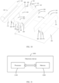
- an embodiment of this application further provides an electronic device 1000 including a processor 1100, a memory 1200, and a program or instructions stored in the memory 1200 and capable of running on the processor 1100, where when the program or instructions are executed by the processor 1100, the processes of the foregoing control method are implemented, with the same technical effects achieved. To avoid repetition, details are not further described herein.
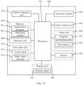
- FIG. 12 is a schematic diagram of a hardware structure of an electronic device according to an embodiment of this application.
- the electronic device 900 includes but is not limited to components such as a radio frequency unit 910, a network module 920, an audio output unit 930, an input unit 940, a sensor 950, a display unit 960, a user input unit 970, an interface unit 980, a memory 990, and a processor 901.
- the electronic device 900 may further include a power supply (for example, a battery) supplying power to the components.
- the power supply may be logically connected to the processor 901 via a power management system, so that functions such as charge management, discharge management, and power consumption management are implemented via the power management system.
- the structure of the electronic device shown in FIG. 12 does not constitute a limitation on the electronic device.
- the electronic device may include more or fewer components than shown in the drawing, or combine some of the components, or arrange the components differently. Details are not described herein.
- the processor 901 is configured to control the sound emitter 400 to emit sound and obtain a state parameter of a flexible display 300 based on sound reception signals of a first sound receiver 510 and a second sound receiver 520, so that the sound reception signals of the first sound receiver 510 and the second sound receiver 520 can be combined to accurately determine the state parameter of the flexible display 300, thereby facilitating the implementation of functions such as directional recording.
- the input unit 940 may include a graphics processing unit (Graphics Processing Unit, GPU) 941 and a microphone 942.
- the graphics processing unit 941 processes image data of a static picture or a video that is obtained by an image capture apparatus (for example, a camera) in a video capture mode or an image capture mode.
- the display unit 960 may include a display panel 961.
- the display panel 961 may be configured in a form of a liquid crystal display, an organic light-emitting diode display, or the like.
- the user input unit 970 includes a touch panel 971 and other input devices 972.
- the touch panel 971 is also referred to as a touchscreen.
- the touch panel 971 may include two parts: a touch detection apparatus and a touch controller.
- the other input devices 972 may include but are not limited to a physical keyboard, a functional button (such as a volume control button or a power on/off button), a trackball, a mouse, and a joystick. Details are not described herein.
- the memory 990 may be configured to store software programs and various data which include but are not limited to an application program 991 and an operating system 992.
- the processor 901 may integrate an application processor and a modem processor.
- the application processor mainly processes the operating system, a user interface, an application program, and the like.
- the modem processor mainly processes wireless communication. It can be understood that the modem processor may alternatively be not integrated in the processor.
- An embodiment of this application further provides a readable storage medium, where the readable storage medium stores a program or instructions, and when the program or instructions are executed by a processor, the processes of the foregoing control method embodiments are implemented, with the same technical effects achieved. To avoid repetition, details are not described herein again.
- the processor is the processor in the electronic device in the foregoing embodiments.
- the readable storage medium includes a computer-readable storage medium such as a computer read-only memory (Read-Only Memory, ROM), a random access memory (Random Access Memory, RAM), a magnetic disk, or an optical disc.
- the computer software product is stored in a storage medium (for example, a ROM/RAM, a magnetic disk, or an optical disc), and includes several instructions for instructing a terminal (which may be a mobile phone, a computer, a server, an air conditioner, a network device, or the like) to perform the method described in the embodiments of this application.
- a storage medium for example, a ROM/RAM, a magnetic disk, or an optical disc
- a terminal which may be a mobile phone, a computer, a server, an air conditioner, a network device, or the like
Landscapes
- Engineering & Computer Science (AREA)
- Theoretical Computer Science (AREA)
- Computer Hardware Design (AREA)
- Physics & Mathematics (AREA)
- General Physics & Mathematics (AREA)
- General Engineering & Computer Science (AREA)
- Human Computer Interaction (AREA)
- Signal Processing (AREA)
- Radar, Positioning & Navigation (AREA)
- Remote Sensing (AREA)
- Acoustics & Sound (AREA)
- Computer Networks & Wireless Communication (AREA)
- Multimedia (AREA)
- Health & Medical Sciences (AREA)
- Audiology, Speech & Language Pathology (AREA)
- General Health & Medical Sciences (AREA)
- Mathematical Physics (AREA)
- Telephone Set Structure (AREA)
- Measurement Of Velocity Or Position Using Acoustic Or Ultrasonic Waves (AREA)
Abstract
Description
- The present invention claims priority to
Chinese Patent Application No. 202110646410.3, filed with the China National Intellectual Property Administration on June 10, 2021 - This application pertains to the field of communication technologies and specifically relates to an electronic device, a control method and control apparatus therefor, and a readable storage medium.
- With the development of communication technology, electronic devices are continuously moving towards full-screen designs, with increasingly large displays. Large displays can not only enhance the aesthetics of electronic devices but also provide users with good visual impact. For activities such as gaming, browsing information, or watching movies, a large display can provide good user experience.
- To increase screen-to-body ratios and control sizes of electronic devices to facilitate the portability of the electronic devices, rollable flexible displays have been increasingly widely used in the electronic devices. Such flexible display can be rolled in a housing of an electronic device and can also extend out of the housing to be unrolled, so as to provide a large display region. An electronic device further includes sound receivers such as microphones. During unrolling and rolling of a flexible display, the sound receivers remain stationary. Therefore, the rollable characteristic of the flexible display is not fully used in arrangement of such sound receivers, resulting in a low structural utilization of the electronic device.
- Embodiments of this application are intended to provide an electronic device, a control method and control apparatus therefor, and a readable storage medium, which can solve the problem of a low structural utilization of a current electronic device caused by sound receivers remaining stationary during unrolling and rolling of a flexible display.
- To resolve the foregoing technical problem, this application is implemented as follows.
- According to a first aspect, an embodiment of this application provides an electronic device. The electronic device includes a first housing, a second housing, a flexible display, a sound emitter, a first sound receiver, a second sound receiver, and a third sound receiver, where
- the first housing is connected to the second housing via the flexible display, and the second housing is capable of moving relative to the first housing such that the flexible display switches between a rolled state and an unrolled state;
- the sound emitter is disposed inside the first housing, a first sound outlet hole is provided in a surface of the first housing, and the sound emitter is in communication with the outside via the first sound outlet hole;
- the first sound receiver is disposed inside the second housing, a first sound receiving hole is provided in a surface of the second housing, and the first sound receiver is in communication with the first sound receiving hole; and the second sound receiver and the third sound receiver are both disposed inside the first housing, a second sound receiving hole and a third sound receiving hole are further provided in the surface of the first housing, the second sound receiver is in communication with the outside via the second sound receiving hole, the third sound receiver is in communication with the outside via the third sound receiving hole, and the second sound receiving hole and the third sound receiving hole are respectively located on two sides of the first housing facing away from each other; and
- in a case that the flexible display is in the rolled state, the first housing covers the first sound receiving hole; and in a case that the flexible display is in the unrolled state, the first sound receiving hole is exposed, and the first sound receiver is in communication with the outside via the first sound receiving hole.
- According to a second aspect, an embodiment of this application further provides a control method for electronic device. The control method includes:
- controlling a sound emitter to emit sound; and
- obtaining a state parameter of a flexible display based on sound reception signals of a first sound receiver and a second sound receiver.
- According to a third aspect, an embodiment of this application further provides a control apparatus for electronic device. The control apparatus includes:
- a control module configured to control a sound emitter to emit sound; and
- a processing module configured to obtain a state parameter of a flexible display based on sound reception signals of a first sound receiver and a second sound receiver.
- According to a fourth aspect, an embodiment of this application provides an electronic device, where the electronic device includes a processor, a memory, and a program or instructions stored in the memory and capable of running on the processor, and when the program or instructions are executed by the processor, the steps of the foregoing control method are implemented.
- According to a fifth aspect, an embodiment of this application provides a readable storage medium, where the readable storage medium stores a program or instructions, and when the program or instructions are executed by a processor, the steps of the foregoing control method are implemented.
- In the embodiments of this application, the flexible display can switch between the rolled state and the unrolled state. When the flexible display is in the rolled state, the first housing covers the first sound receiving hole, allowing the sound emitted by the sound emitter to be picked up by the second sound receiver but not the first sound receiver. When the flexible display is in the unrolled state, the first sound receiving hole is exposed, allowing the sound emitted by the sound emitter to be picked up by both the first sound receiver and the second sound receiver. The state of the flexible display and a position of the first sound receiver can be determined by detecting whether the first sound receiver picks up a sound signal and based on parameters of the sound signals picked up by the first sound receiver and the second sound receiver. With this solution, the first sound receiver can move with the second housing, allowing the position of the first sound receiver to change, and implementing functions such as directional recording based on this. It can be seen that the embodiments can make full use of the rollable characteristic of the flexible display, thereby implementing more functions and achieving a higher structural utilization of the electronic device.
-
-
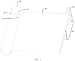
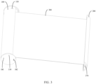
FIG. 1 to FIG. 3 are schematic structural diagrams of an electronic device according to a first embodiment of this application from different perspectives; -
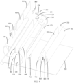
FIG. 4 is an exploded view of the electronic device according to the first embodiment of this application; -
FIG. 5 is a diagram showing a relationship between sound reception signal intensities received by a first sound receiver and a second sound receiver and unrolling distance during unrolling of the flexible display according to the first embodiment of this application; -
FIG. 6 is a diagram showing variations of sound reception signal intensities received by a first sound receiver and a second sound receiver when the electronic device according to the first embodiment is shielded by a foreign object; -
FIG. 7 to FIG. 9 are schematic structural diagrams of an electronic device according to a second embodiment of this application from different perspectives; -
FIG. 10 is an exploded view of the electronic device according to the second embodiment of this application; -
FIG. 11 is a structural block diagram of an electronic device according to an embodiment of this application; and -
FIG. 12 is a schematic diagram of a hardware structure of an electronic device according to an embodiment of this application. - Description of reference signs:
- 100. first housing; 110. first sound outlet hole; 120. second sound receiving hole; 130. third sound receiving hole; 140. first body portion; 150. first end plate; 160. second end plate; 171. first cover plate; 172. second cover plate; 181. second sound outlet hole; 182, fourth sound outlet hole; 183. light through hole;
- 200. second housing; 210. first sound receiving hole; 220. first surface; 230. second surface; 240. third surface; 250. housing body; 251. second body portion; 252. third cover plate; 260. protrusion; 270. third sound outlet hole;
- 300. flexible display;
- 400. sound emitter;
- 510. first sound receiver; 520, second sound receiver, 530. third sound receiver;
- 600. rolling shaft;
- 710. first magnetic member; 720. second magnetic member;
- 810. circuit board; 820. battery; 830. first speaker; 840. first sealing member; 850, second speaker; 860. second sealing member; 870, third sealing member; 880, camera; 890, fourth sealing member;
- 900. electronic device; 901. processor; 910. radio frequency unit; 920. network module; 930. audio output unit; 940. input unit; 941. graphics processing unit; 942. microphone; 950. sensor; 960. display unit; 961. display panel; 970. user input unit; 971. touch panel; 972. other input devices; 980. interface unit; 990. memory; 991. application program; 992. operating system;
- 1000. electronic device; 1100. processor; and 1200. memory.
- The following clearly and completely describes the technical solutions in the embodiments of this application with reference to the accompanying drawings in the embodiments of this application. Apparently, the described embodiments are only some rather than all of the embodiments of this application. All other embodiments obtained by persons of ordinary skill in the art based on the embodiments of this application without creative efforts shall fall within the protection scope of this application.
- The terms "first", "second", and the like in the specification and claims of this application are used to distinguish between similar objects rather than to describe a specific order or sequence. It should be understood that data used in this way are interchangeable in appropriate circumstances such that the embodiments of this application can be implemented in other orders than the order illustrated or described herein. In addition, in this specification and claims, "and/or" indicates at least one of the connected objects, and the character "/" generally indicates an "or" relationship between the contextually associated objects.
- The following describes in detail an electronic device provided in the embodiments of this application through specific embodiments and application scenarios thereof with reference to the accompanying drawings.
- Referring to
FIG. 1 to FIG. 6 , an embodiment of this application provides an electronic device. The electronic device includes afirst housing 100, asecond housing 200, aflexible display 300, asound emitter 400, afirst sound receiver 510, asecond sound receiver 520, and athird sound receiver 530. - The
first housing 100 is connected to thesecond housing 200 via theflexible display 300. Thesecond housing 200 can move relative to thefirst housing 100 such that theflexible display 300 switches between a rolled state and an unrolled state. Optionally, thefirst housing 100 and thesecond housing 200 may not be directly connected. One end of theflexible display 300 is connected to thefirst housing 100, and the other end of theflexible display 300 is connected to thesecond housing 200. A user can manually apply an action force to either thefirst housing 100 or thesecond housing 200, or to both thefirst housing 100 and thesecond housing 200, allowing thesecond housing 200 to leave or approach thefirst housing 100, so that theflexible display 300 switches between the rolled state and the unrolled state, thereby changing a size of a portion located outside both thefirst housing 100 and thesecond housing 200 in theflexible display 300 to change a size of a display region of the electronic device and an overall size of the electronic device. To facilitate rolling of theflexible display 300, a rollingshaft 600 may be disposed inside thefirst housing 100, and one end of theflexible display 300 is rolled around the rollingshaft 600. When theflexible display 300 switches between the rolled state and the unrolled state, theflexible display 300 may be gradually rolled around the rollingshaft 600 or gradually separated from the rollingshaft 600. - The
sound emitter 400 is disposed inside thefirst housing 100, and a firstsound outlet hole 110 is provided in a surface of thefirst housing 100. Thesound emitter 400 is in communication with the outside via the firstsound outlet hole 110, and sound emitted by thesound emitter 400 may be transmitted to the outside via the firstsound outlet hole 110. Optionally, sound waves emitted by thesound emitter 400 may be audible sound, in which case all of thefirst sound receiver 510, thesecond sound receiver 520, and thethird sound receiver 530 are components capable of receiving audible sound. Alternatively, sound waves emitted by thesound emitter 400 may be ultrasonic waves, and correspondingly, all of thefirst sound receiver 510, thesecond sound receiver 520, and thethird sound receiver 530 are components capable of receiving ultrasonic waves. Certainly, thesound emitter 400 may alternatively be a component capable of emitting both audible sound and ultrasonic waves, and correspondingly, all of thefirst sound receiver 510, thesecond sound receiver 520, and thethird sound receiver 530 are components capable of receiving both audible sound and ultrasonic waves. Comparatively, when the sound waves emitted by thesound emitter 400 are ultrasonic waves, the user cannot hear the sound emitted by thesound emitter 400 during operation of thesound emitter 400, which can provide good user experience. Therefore, thesound emitter 400 can be designated as an ultrasonic emitter. Optionally, thesound emitter 400 may be a receiver, and thefirst sound receiver 510, thesecond sound receiver 520, and thethird sound receiver 530 may all be microphones, which can make full use of the existing components of the electronic device, thereby reducing the cost and component stacking complexity of the electronic device. - The
first sound receiver 510 is disposed inside thesecond housing 200, a firstsound receiving hole 210 is provided in a surface of thesecond housing 200, and thefirst sound receiver 510 is in communication with the firstsound receiving hole 210. In a case that theflexible display 300 is in the rolled state, thefirst housing 100 covers the firstsound receiving hole 210, in which case the firstsound receiving hole 210 cannot be in communication with the outside, and therefore thefirst sound receiver 510 cannot receive sound. In a case that theflexible display 300 is in the unrolled state, the firstsound receiving hole 210 is exposed, and thefirst sound receiver 510 is in communication with the outside via the firstsound receiving hole 210 and thus can receive the sound. In other words, the state of the firstsound receiving hole 210 changes with the state of theflexible display 300, thereby changing the operation state of thefirst sound receiver 510. - The
second sound receiver 520 and thethird sound receiver 530 are both disposed inside thefirst housing 100. A secondsound receiving hole 120 and a thirdsound receiving hole 130 are provided in the surface of thefirst housing 100, where thesecond sound receiver 520 is in communication with the outside via the secondsound receiving hole 120, thethird sound receiver 530 is in communication with the outside via the thirdsound receiving hole 130, and the secondsound receiving hole 120 and the thirdsound receiving hole 130 are respectively located on two sides of thefirst housing 100 facing away from each other. The secondsound receiving hole 120 and the thirdsound receiving hole 130 are always in communication with the outside. Therefore, regardless of changes in the state of theflexible display 300, thesecond sound receiver 520 and thethird sound receiver 530 can always receive sound. In the case that theflexible display 300 is in the rolled state, functions such as recording can be implemented by thesecond sound receiver 520 and thethird sound receiver 530. - In this embodiment of this application, the
flexible display 300 can switch between the rolled state and the unrolled state. When theflexible display 300 is in the rolled state, thefirst housing 100 covers the firstsound receiving hole 210, allowing the sound emitted by thesound emitter 400 to be picked up by thesecond sound receiver 520 but not thefirst sound receiver 510. When theflexible display 300 is in the unrolled state, the firstsound receiving hole 210 is exposed, allowing the sound emitted by thesound emitter 400 to be picked up by both thefirst sound receiver 510 and thesecond sound receiver 520. The state of theflexible display 300 and a position of thefirst sound receiver 510 can be determined by detecting whether thefirst sound receiver 510 picks up a sound signal and based on parameters of the sound signals picked up by thefirst sound receiver 510 and thesecond sound receiver 520. With this solution, thefirst sound receiver 510 can move with thesecond housing 200, allowing the position of thefirst sound receiver 510 to change, and implementing functions such as directional recording based on this. It can be seen that this embodiment can make full use of the rollable characteristic of theflexible display 300, thereby implementing more functions and achieving a higher structural utilization of the electronic device. In addition, the state of theflexible display 300 can be determined using thefirst sound receiver 510 and thesecond sound receiver 520. Therefore, there is no need to provide additional components to detect the state of theflexible display 300, which indicates that this solution can also reduce the cost and component stacking complexity of the electronic device. - In an optional embodiment, the
second housing 200 has afirst surface 220 and asecond surface 230, thefirst surface 220 and thesecond surface 230 facing away from each other in a direction parallel to the rollingshaft 600, and thefirst surface 220 being provided with the firstsound receiving hole 210. In other words, the firstsound receiving hole 210 may be provided in an end face of thesecond housing 200. To cover the firstsound receiving hole 210 when theflexible display 300 is in the rolled state, thefirst housing 100 may be provided with an outward extension portion. When theflexible display 300 is in the rolled state, the outward extension portion is located on an outer side of thesecond housing 200 to cover the firstsound receiving hole 210. In this embodiment, since the outward extension portion of thefirst housing 100 has a specified size, during gradual rolling of theflexible display 300, when an edge of the outward extension portion reaches the position of the firstsound receiving hole 210, with thesecond housing 200 further gradually approaching thefirst housing 100, the outward extension portion can maintain a state of shielding the firstsound receiving hole 210 for a period of time until thesecond housing 200 no longer approaches thefirst housing 100. Conversely, during gradual unrolling of theflexible display 300, when thesecond housing 200 starts leaving thefirst housing 100, the outward extension portion can maintain the state of shielding the firstsound receiving hole 210 for a period of time until the outward extension portion does not shield the firstsound receiving hole 210 at all. Then thesecond housing 200 can continue to leave thefirst housing 100. It can be seen that this embodiment can allow thefirst housing 100 to shield the firstsound receiving hole 210 for a long time, thereby enhancing the shielding effect of the firstsound receiving hole 210. - In another optional embodiment, as shown in
FIG. 7 to FIG. 10 , thesecond housing 200 has athird surface 240, thethird surface 240 being provided with the firstsound receiving hole 210; and in a case that theflexible display 300 is in the unrolled state, thethird surface 240 faces thefirst housing 100. With such arrangement, the firstsound receiving hole 210 is provided at a position of thesecond housing 200 closer to thesound emitter 400, so that thefirst sound receiver 510 can more easily pick up sound signals emitted by thesound emitter 400. Therefore, this embodiment can enhance the sensitivity of thefirst sound receiver 510. - Two ends of the
first housing 100 in the direction parallel to the rollingshaft 600 are a first end and a second end, and two ends of thesecond housing 200 in the direction parallel to the rollingshaft 600 are a third end and a fourth end, the first end and the third end being located on a same side, and the second end and the fourth end being located on a same side. Optionally, the firstsound outlet hole 110 is provided in the first end, and the firstsound receiving hole 210 is provided in the fourth end, that is, the firstsound outlet hole 110 and the firstsound receiving hole 210 are provided in different sides of the electronic device. Alternatively, the firstsound outlet hole 110 is provided in the first end, and the firstsound receiving hole 210 is provided in the third end, that is, the firstsound outlet hole 110 and the firstsound receiving hole 210 are provided in a same side of the electronic device. Comparatively, in the latter embodiment, a shorter distance is present between the firstsound outlet hole 110 and the firstsound receiving hole 210, which is more conducive to picking up clearer sound signals by thefirst sound receiver 510. - In the optional embodiment, the
second housing 200 includes ahousing body 250 and aprotrusion 260, where theprotrusion 260 is disposed at an end of thehousing body 250, the end is provided with the firstsound receiving hole 210, and theprotrusion 260 protrudes relative to the firstsound receiving hole 210. In the case that theflexible display 300 is in the unrolled state, the firstsound receiving hole 210 is located between thefirst housing 100 and theprotrusion 260. Theprotrusion 260 here can simulate the user's ear, which is more conducive to distinguishing directions of sound signals, thereby determining sound directions more accurately to improve the recording effect. - Optionally, the
first housing 100 may include afirst body portion 140, afirst end plate 150, asecond end plate 160, afirst cover plate 171, and asecond cover plate 172. Thefirst body portion 140 may be a cylindrical structure. Thefirst end plate 150 and thesecond end plate 160 are respectively disposed at two ends of thefirst body portion 140. Thefirst cover plate 171 is disposed inside thefirst body portion 140. Acircuit board 810, abattery 820, afirst speaker 830, and acamera 880 may be disposed inside a space enclosed by thefirst cover plate 171 and thefirst body portion 140. A secondsound outlet hole 181 is formed in thefirst end plate 150, and thefirst speaker 830 may be in communication with the outside via the secondsound outlet hole 181. Thefirst body portion 140 is provided with a light throughhole 183, and thecamera 880 is positioned opposite to the light throughhole 183. Thesecond cover plate 172 is disposed inside thefirst body portion 140, and thesound emitter 400, thesecond sound receiver 520, thethird sound receiver 530, and the rollingshaft 600 may be disposed inside a space between thefirst cover plate 171 and thesecond cover plate 172. In the case that theflexible display 300 is in the rolled state, thesecond housing 200 and thefirst housing 100 together form a cylindrical structure, helping a user to roll the electronic device. Thehousing body 250 of thesecond housing 200 may include asecond body portion 251 and athird cover plate 252, where thesecond body portion 251 may be a cylindrical structure, thethird cover plate 252 is connected to thesecond body portion 251, and thefirst sound receiver 510 and asecond speaker 850 are disposed inside a space enclosed by thesecond body portion 251 and thethird cover plate 252. Thefirst housing 100 is further provided with a fourthsound outlet hole 182, and thesecond body portion 251 is provided with a thirdsound outlet hole 270. In the case that theflexible display 300 is in the rolled state, the thirdsound outlet hole 270 faces the fourthsound outlet hole 182, and thesecond speaker 850 is in communication with the outside via the thirdsound outlet hole 270 and the fourthsound outlet hole 182. In the case that theflexible display 300 is in the unrolled state, thesecond speaker 850 is in communication with the outside via only the thirdsound outlet hole 270. - In addition, a
first sealing member 840 may be disposed at the secondsound outlet hole 181, and thefirst speaker 830 may be in hermetical communication with the secondsound outlet hole 181 via thefirst sealing member 840. Asecond sealing member 860 may be disposed at the thirdsound outlet hole 270, and thesecond speaker 850 may be in hermetical communication with the thirdsound outlet hole 270 via thesecond sealing member 860. Athird sealing member 870 may be disposed at the firstsound outlet hole 110, and thesound emitter 400 may be in hermetical communication with the firstsound outlet hole 110 via thethird sealing member 870. When thethird surface 240 of thesecond housing 200 is provided with the firstsound receiving hole 210, afourth sealing member 890 may be disposed on an outer surface of the first housing 100 (specifically, the first cover plate 171). In the case that theflexible display 300 is in the rolled state, thefourth sealing member 890 blocks the firstsound receiving hole 210 to seal the firstsound receiving hole 210. - Further, the electronic device further includes a first
magnetic member 710 and a secondmagnetic member 720. Optionally, both the firstmagnetic member 710 and the secondmagnetic member 720 may be magnets. The firstmagnetic member 710 is disposed on thefirst housing 100, and the secondmagnetic member 720 is disposed on thesecond housing 200. In the case that theflexible display 300 is in the rolled state, the firstmagnetic member 710 is in magnetic attraction with the secondmagnetic member 720, making it difficult for thefirst housing 100 and thesecond housing 200 to separate, thereby keeping theflexible display 300 in the rolled state more reliably. Still further, the firstmagnetic member 710 is disposed on a surface of thefirst housing 100 facing thesecond housing 200, and the secondmagnetic member 720 is disposed on a surface of thesecond housing 200 facing thefirst housing 100. When theflexible display 300 is in the rolled state, a shorter distance is present between the firstmagnetic member 710 and the secondmagnetic member 720 such that the two magnetic members can be in direct contact with each other, which forms a greater action force between the two magnetic members, thereby improving the reliability of keeping theflexible display 300 in the rolled state. - Based on the electronic device disclosed in any of the foregoing embodiments, an embodiment of this application further discloses a control method for electronic device. The control method includes the following steps.
- S100. Control a
sound emitter 400 to emit sound. - S200. Obtain a state parameter of a
flexible display 300 based on sound reception signals of afirst sound receiver 510 and asecond sound receiver 520. - After the
sound emitter 400 emits a sound, since a secondsound receiving hole 120 is always in communication with the outside, thesecond sound receiver 520 can always receive sound signals emitted by thesound emitter 400. For thefirst sound receiver 510, when theflexible display 300 is in a rolled state, a firstsound receiving hole 210 is covered, so thefirst sound receiver 510 cannot receive the sound signals. When theflexible display 300 is in an unrolled state, the firstsound receiving hole 210 is in communication with the outside, so thefirst sound receiver 510 can receive the sound signals emitted by thesound emitter 400. In addition, during continuous unrolling of theflexible display 300, asecond housing 200 reflects some sound waves emitted by thesound emitter 400 to thesecond sound receiver 520, causing changes in the sound signals received by thesecond sound receiver 520. Therefore, combining the sound reception signals of thefirst sound receiver 510 and thesecond sound receiver 520 can accurately determine the state parameter of theflexible display 300, facilitating the implementation of functions such as directional recording. - Optionally, the foregoing state parameter may include unrolling distance, where the unrolling distance refers to a length variation of the
flexible display 300 during unrolling of theflexible display 300 and also represents a movement distance of thesecond housing 200. Since thefirst sound receiver 510 is provided on thesecond housing 200, thefirst sound receiver 510 is related to the unrolling distance. Obtaining the unrolling distance can determine a position of thefirst sound receiver 510, facilitating the implementation of functions such as directional recording. Based on this, step S200 specifically includes the following steps. - S210. Obtain a current state of the
flexible display 300 based on intensity of a first sound reception signal received by thefirst sound receiver 510 and intensity of a second sound reception signal received by thesecond sound receiver 520. - The current state of the
flexible display 300 here may include the unrolled state and the rolled state. As shown inFIG. 5 , it should be noted that the unrolling distance inFIG. 5 is measured in cm, and the sound reception signal intensity is measured in dB. When theflexible display 300 is in the rolled state, the unrolling distance is 0, thefirst sound receiver 510 is shielded by thefirst housing 100, and thefirst sound receiver 510 cannot receive sound signals; and the intensity of the first sound reception signal is 0, and thesecond sound receiver 520 receives sound signals with constant intensity. In this case, the intensity of the second sound reception signal is a non-zero fixed value. As theflexible display 300 is continuously unrolled, the unrolling distance gradually increases. The firstsound receiving hole 210 undergoes a state from completely blocked to partially blocked and then completely unblocked. During this process, the intensity of the first sound reception signal quickly increases and reaches its maximum value. Due to the reflection of thesecond housing 200, the sound signals picked up by thesecond sound receiver 520 are also enhanced to some extent. Then, with an increasingly large unrolling distance of thesecond housing 200, an increasingly large distance is present between thefirst sound receiver 510 and thesound emitter 400, the intensity of the first sound reception signal attenuates inversely proportional to the square of the unrolling distance, and the reflection effect of thesecond housing 200 on the sound signals is increasingly weak, gradually restoring the intensity of the second sound reception signal to its initial value. - S220. When the current state of the
flexible display 300 is the unrolled state, obtain corresponding unrolling distances based on the intensity of the first sound reception signal and the intensity of the second sound reception signal. - As described above, when the
flexible display 300 is in the unrolled state, the unrolling distance of theflexible display 300 is related to both the intensity of the first sound reception signal and the intensity of the second sound reception signal. Therefore, the unrolling distance of theflexible display 300 can be obtained based on the intensity of the first sound reception signal and the intensity of the second sound reception signal, thereby obtaining the position of thefirst sound receiver 510. In this embodiment, the intensity of the first sound reception signal and the intensity of the second sound reception signal can be easily detected, and the intensity of the first sound reception signal and the intensity of the second sound reception signal each have a clear relationship with the unrolling distance. Therefore, this embodiment can more accurately obtain the position of thefirst sound receiver 510. - It can be seen from
FIG. 5 that the intensity of the first sound reception signal and the intensity of the second sound reception signal are related to but not in a monotonic function relationship with the unrolling distance of theflexible display 300. Therefore, there are still some limitations in obtaining the unrolling distance of theflexible display 300 based on only the intensity of the first sound reception signal and the intensity of the second sound reception signal. In view of this, to more accurately obtain the unrolling distance of theflexible display 300, step S220 of obtaining corresponding unrolling distances based on the intensity of the first sound reception signal and the intensity of the second sound reception signal specifically includes the following steps. - S221. Measure a duration required for the
first sound receiver 510 to pick up a sound signal emitted by thesound emitter 400. - S222. Obtain corresponding unrolling distances based on the duration, the intensity of the first sound reception signal, and the intensity of the second sound reception signal.
- The sound signal emitted by the
sound emitter 400 propagates to thefirst sound receiver 510 after a certain period of time. A propagation distance of the sound signal is basically equal to the unrolling distance of theflexible display 300, and the propagation distance of the sound signal is directly proportional to the duration. In addition, due to a limitation on an audio sampling rate, taking an audio sampling rate of 96K as an example, a corresponding sampling period is approximately 10.4 µs, and a corresponding propagation distance is 0.35 cm, that is, a distance resolution is only 0.35 cm. Therefore, if the unrolling distance of theflexible display 300 is determined based on only the duration required for thefirst sound receiver 510 to pick up the sound signal emitted by thesound emitter 400, there is still a problem of low accuracy. On the contrary, if the unrolling distance of theflexible display 300 is obtained based on all of the duration, the intensity of the first sound reception signal, and the intensity of the second sound reception signal, the unrolling distance of theflexible display 300 can be obtained more accurately. - Optionally, the corresponding unrolling distances can be first determined based on the intensity of the first sound reception signal and the intensity of the second sound reception signal. Then, when there are two values for the unrolling distance, calculation may be further performed based on the duration to further determine the unrolling distance. In another optional embodiment, step S222 specifically includes the following steps.
- S2221. Obtain an estimated unrolling distance based on the duration.
- S2222. Obtain, based on the estimated unrolling distance, a monotonic interval in which the intensity of the first sound reception signal and the intensity of the second sound reception signal are located.
- S2223. Obtain, based on the intensity of the first sound reception signal and the intensity of the second sound reception signal, corresponding unrolling distances for the two intensities in the monotonic interval.
- To be specific, after the sound signal is emitted by the
sound emitter 400, the duration required for thefirst sound receiver 510 to pick up the sound signal is recorded. The estimated unrolling distance is calculated based on the duration and a propagation speed of the sound signal. Then, a monotonic interval corresponding to the estimated unrolling distance is looked up in a relationship table of the intensity of the first sound reception signal, the intensity of the second sound reception signal, and the unrolling distance. Further, based on the intensity of the first sound reception signal and the intensity of the second sound reception signal, the corresponding unrolling distances for the two intensities in the monotonic interval are obtained, thereby calibrating the unrolling distance to obtain a more accurate unrolling distance. The control method can simplify control procedures to more quickly and more accurately obtain the unrolling distance of theflexible display 300. - The control method can obtain the unrolling distance of the
flexible display 300. The unrolling distance can be used to control states of other components of the electronic device. These components may include theflexible display 300, a camera, afirst speaker 830, asecond speaker 850, and the like. In an optional embodiment, the unrolling distance of theflexible display 300 can be used to implement directional recording. In this case, the control method further includes the following step. - S300. Match a corresponding directional recording parameter based on the unrolling distance.
- In other words, after the unrolling distance of the
flexible display 300 is obtained, the corresponding directional recording parameter can be further matched based on the unrolling distance, allowing the electronic device to implement directional recording by using thefirst sound receiver 510, thesecond sound receiver 520, and thethird sound receiver 530, thereby improving the recording effect of the electronic device. - In another embodiment, step S200 specifically includes the following steps.
- S230. Obtain a current state of the
flexible display 300 based on intensity of a first sound reception signal received by thefirst sound receiver 510 and intensity of a second sound reception signal received by thesecond sound receiver 520. - S240. In a case that the current state of the
flexible display 300 is a rolled state, performing operations corresponding to the rolled state. - As shown in
FIG. 6 , it should be noted that the state inFIG. 6 is a state indicating whether the electronic device is shielded by a foreign object, and the sound reception signal intensity is measured in dB. When theflexible display 300 is in the rolled state, the firstsound receiving hole 210 is shielded by thefirst housing 100, so the intensity of the first sound reception signal is always 0. If there is a foreign object around the electronic device, for example, when the electronic device is placed in a pocket, with an increasingly large shielding degree, some sound signals emitted by thesound emitter 400 are reflected by the foreign object to the secondsound receiving hole 120, resulting in an increase in the intensity of the second sound reception signal. Therefore, proximity test can be performed based on the intensity of the first sound reception signal and the intensity of the second sound reception signal, allowing the electronic device to perform the operations corresponding to the rolled state, for example, retracting the camera and turning off the speaker. - Based on the control method disclosed in any of the foregoing embodiments, an embodiment of this application further discloses a control apparatus for electronic device. The control apparatus includes:
- a control module configured to control a
sound emitter 400 to emit sound; and - a processing module configured to obtain a state parameter of a
flexible display 300 based on sound reception signals of afirst sound receiver 510 and asecond sound receiver 520. - The control apparatus can combine the sound reception signals of the
first sound receiver 510 and thesecond sound receiver 520 to accurately determine the state parameter of theflexible display 300, facilitating the implementation of functions such as directional recording. - The control apparatus in this embodiment of this application may be an apparatus or a component, integrated circuit, or chip in a terminal. The apparatus may be a mobile electronic device or a non-mobile electronic device. For example, the mobile electronic device may be a mobile phone, a tablet computer, a notebook computer, a palmtop computer, a vehicular electronic device, a wearable device, an ultra-mobile personal computer (UMPC), a netbook, a personal digital assistant (personal digital assistant, PDA), or the like; and the non-mobile electronic device may be a server, a network attached storage (Network Attached Storage, NAS), a personal computer (personal computer, PC), a television (television, TV), a teller machine, a self-service machine, or the like. This is not specifically limited in this embodiment of this application.
- The control apparatus in this embodiment of this application may be an apparatus having an operating system. The operating system may be an android (Android) operating system, may be an iOS operating system, or may be another possible operating system. This is not specifically limited in this embodiment of this application.
- Optionally, as shown in
FIG. 11 , an embodiment of this application further provides anelectronic device 1000 including aprocessor 1100, amemory 1200, and a program or instructions stored in thememory 1200 and capable of running on theprocessor 1100, where when the program or instructions are executed by theprocessor 1100, the processes of the foregoing control method are implemented, with the same technical effects achieved. To avoid repetition, details are not further described herein. -
FIG. 12 is a schematic diagram of a hardware structure of an electronic device according to an embodiment of this application. - The
electronic device 900 includes but is not limited to components such as aradio frequency unit 910, anetwork module 920, anaudio output unit 930, aninput unit 940, asensor 950, adisplay unit 960, auser input unit 970, aninterface unit 980, amemory 990, and aprocessor 901. - It can be understood by persons skilled in the art that the
electronic device 900 may further include a power supply (for example, a battery) supplying power to the components. The power supply may be logically connected to theprocessor 901 via a power management system, so that functions such as charge management, discharge management, and power consumption management are implemented via the power management system. The structure of the electronic device shown inFIG. 12 does not constitute a limitation on the electronic device. The electronic device may include more or fewer components than shown in the drawing, or combine some of the components, or arrange the components differently. Details are not described herein. - The
processor 901 is configured to control thesound emitter 400 to emit sound and obtain a state parameter of aflexible display 300 based on sound reception signals of afirst sound receiver 510 and asecond sound receiver 520, so that the sound reception signals of thefirst sound receiver 510 and thesecond sound receiver 520 can be combined to accurately determine the state parameter of theflexible display 300, thereby facilitating the implementation of functions such as directional recording. - It should be understood that in this embodiment of this application, the
input unit 940 may include a graphics processing unit (Graphics Processing Unit, GPU) 941 and amicrophone 942. Thegraphics processing unit 941 processes image data of a static picture or a video that is obtained by an image capture apparatus (for example, a camera) in a video capture mode or an image capture mode. Thedisplay unit 960 may include adisplay panel 961. Thedisplay panel 961 may be configured in a form of a liquid crystal display, an organic light-emitting diode display, or the like. Theuser input unit 970 includes atouch panel 971 andother input devices 972. Thetouch panel 971 is also referred to as a touchscreen. Thetouch panel 971 may include two parts: a touch detection apparatus and a touch controller. Theother input devices 972 may include but are not limited to a physical keyboard, a functional button (such as a volume control button or a power on/off button), a trackball, a mouse, and a joystick. Details are not described herein. Thememory 990 may be configured to store software programs and various data which include but are not limited to anapplication program 991 and anoperating system 992. Theprocessor 901 may integrate an application processor and a modem processor. The application processor mainly processes the operating system, a user interface, an application program, and the like. The modem processor mainly processes wireless communication. It can be understood that the modem processor may alternatively be not integrated in the processor. - An embodiment of this application further provides a readable storage medium, where the readable storage medium stores a program or instructions, and when the program or instructions are executed by a processor, the processes of the foregoing control method embodiments are implemented, with the same technical effects achieved. To avoid repetition, details are not described herein again.
- The processor is the processor in the electronic device in the foregoing embodiments. The readable storage medium includes a computer-readable storage medium such as a computer read-only memory (Read-Only Memory, ROM), a random access memory (Random Access Memory, RAM), a magnetic disk, or an optical disc.
- It should be noted that in this specification, the terms "include", "comprise", or any of their variants are intended to cover a non-exclusive inclusion, so that a process, method, article, or apparatus that includes a series of elements includes not only those elements but also other elements that are not expressly listed, or further includes elements inherent to such process, method, article, or apparatus. Without more constraints, an element preceded by "includes a..." does not preclude the presence of other identical elements in the process, method, article, or apparatus that includes the element. In addition, it should be noted that the scope of the method and apparatus in the implementations of this application is not limited to functions being performed in the order shown or discussed, but may further include functions being performed at substantially the same time or in a reverse order, depending on the functions involved. For example, the described method may be performed in an order different from the order described, and steps may be added, omitted, or combined. In addition, features described with reference to some examples may be combined in other examples.
- According to the description of the foregoing implementations, persons skilled in the art can clearly understand that the method in the foregoing embodiments may be implemented by software in combination with a necessary general hardware platform. Certainly, the method in the foregoing embodiments may alternatively be implemented by hardware. However, in many cases, the former is a preferred implementation. Based on such an understanding, the technical solutions of this application essentially, or the part contributing to the prior art may be implemented in a form of a software product. The computer software product is stored in a storage medium (for example, a ROM/RAM, a magnetic disk, or an optical disc), and includes several instructions for instructing a terminal (which may be a mobile phone, a computer, a server, an air conditioner, a network device, or the like) to perform the method described in the embodiments of this application.
- The foregoing describes the embodiments of this application with reference to the accompanying drawings. However, this application is not limited to the foregoing specific implementations. These specific implementations are merely illustrative rather than restrictive. Inspired by this application, persons of ordinary skill in the art may develop many other forms without departing from the essence of this application and the protection scope of the claims, and all such forms shall fall within the protection scope of this application.
Claims (15)
- An electronic device, comprising a first housing (100), a second housing (200), a flexible display (300), a sound emitter (400), a first sound receiver (510), a second sound receiver (520), and a third sound receiver (530), whereinthe first housing (100) is connected to the second housing (200) via the flexible display (300), and the second housing (200) is capable of moving relative to the first housing (100) such that the flexible display (300) switches between a rolled state and an unrolled state;the sound emitter (400) is disposed inside the first housing (100), a first sound outlet hole (110) is provided in a surface of the first housing (100), and the sound emitter (400) is in communication with the outside via the first sound outlet hole (110);the first sound receiver (510) is disposed inside the second housing (200), a first sound receiving hole (210) is provided in a surface of the second housing (200), and the first sound receiver (510) is in communication with the first sound receiving hole (210); and the second sound receiver (520) and the third sound receiver (530) are both disposed inside the first housing (100), a second sound receiving hole (120) and a third sound receiving hole (130) are further provided in the surface of the first housing (100), the second sound receiver (520) is in communication with the outside via the second sound receiving hole (120), the third sound receiver (530) is in communication with the outside via the third sound receiving hole (130), and the second sound receiving hole (120) and the third sound receiving hole (130) are respectively located on two sides of the first housing (100) facing away from each other; andin a case that the flexible display (300) is in the rolled state, the first housing (100) covers the first sound receiving hole (210); and in a case that the flexible display (300) is in the unrolled state, the first sound receiving hole (210) is exposed, and the first sound receiver (510) is in communication with the outside via the first sound receiving hole (210).
- The electronic device according to claim 1, wherein the first housing (100) is provided with a rolling shaft (600) inside, and one end of the flexible display (300) is rolled around the rolling shaft (600); and the second housing (200) has a first surface (220) and a second surface (230), the first surface (220) and the second surface (230) facing away from each other in a direction parallel to the rolling shaft (600), and the first surface (220) being provided with the first sound receiving hole (210).
- The electronic device according to claim 1, wherein the second housing (200) has a third surface (240), the third surface (240) being provided with the first sound receiving hole (210); and
in a case that the flexible display (300) is in the unrolled state, the third surface (240) faces the first housing (100). - The electronic device according to claim 1, wherein the first housing (100) is provided with a rolling shaft (600) inside, and one end of the flexible display (300) is rolled around the rolling shaft (600); two ends of the first housing (100) in a direction parallel to the rolling shaft (600) are a first end and a second end, and two ends of the second housing (200) in the direction parallel to the rolling shaft (600) are a third end and a fourth end, the first end and the third end being located on a same side, and the second end and the fourth end being located on a same side; and the first sound outlet hole (110) is provided in the first end, and the first sound receiving hole (210) is provided in the third end.
- The electronic device according to claim 1, wherein the second housing (200) comprises a housing body (250) and a protrusion (260), the protrusion (260) being disposed at an end of the housing body (250), the end being provided with the first sound receiving hole (210), and the protrusion (260) protruding relative to the first sound receiving hole (210); and
in a case that the flexible display (300) is in the unrolled state, the first sound receiving hole (210) is located between the first housing (100) and the protrusion (260). - The electronic device according to claim 1, wherein the electronic device further comprises a first magnetic member (710) and a second magnetic member (720), the first magnetic member (710) being disposed on the first housing (100), and the second magnetic member (720) being disposed on the second housing (200); and
in a case that the flexible display (300) is in the rolled state, the first magnetic member (710) is in magnetic attraction with the second magnetic member (720). - A control method for electronic device, comprising:controlling a sound emitter to emit sound; andobtaining a state parameter of a flexible display based on sound reception signals of a first sound receiver and a second sound receiver.
- The control method according to claim 7, wherein the state parameter comprises unrolling distance, and the obtaining a state parameter of a flexible display based on sound reception signals of a first sound receiver and a second sound receiver specifically comprises:obtaining a current state of the flexible display based on intensity of a first sound reception signal received by the first sound receiver and intensity of a second sound reception signal received by the second sound receiver; andin a case that the current state of the flexible display is an unrolled state, obtaining corresponding unrolling distances based on the intensity of the first sound reception signal and the intensity of the second sound reception signal.
- The control method according to claim 8, wherein the obtaining corresponding unrolling distances based on the intensity of the first sound reception signal and the intensity of the second sound reception signal specifically comprises:measuring a duration required for the first sound receiver to pick up a sound signal emitted by the sound emitter; andobtaining corresponding unrolling distances based on the duration, the intensity of the first sound reception signal, and the intensity of the second sound reception signal.
- The control method according to claim 9, wherein the obtaining corresponding unrolling distances based on the duration, the intensity of the first sound reception signal, and the intensity of the second sound reception signal specifically comprises:obtaining an estimated unrolling distance based on the duration;obtaining, based on the estimated unrolling distance, a monotonic interval in which the intensity of the first sound reception signal and the intensity of the second sound reception signal are located; andobtaining, based on the intensity of the first sound reception signal and the intensity of the second sound reception signal, corresponding unrolling distances for the two intensities in the monotonic interval.
- The control method according to any one of claims 8 to 10, wherein the control method further comprises:
matching a corresponding directional recording parameter based on the unrolling distance. - The control method according to claim 7, wherein the obtaining a state parameter of a flexible display based on sound reception signals of a first sound receiver and a second sound receiver specifically comprises:obtaining a current state of the flexible display based on intensity of a first sound reception signal received by the first sound receiver and intensity of a second sound reception signal received by the second sound receiver; andin a case that the current state of the flexible display is a rolled state, performing operations corresponding to the rolled state.
- A control device for electronic device, comprising:a control module configured to control a sound emitter to emit sound; anda processing module configured to obtain a state parameter of a flexible display based on sound reception signals of a first sound receiver and a second sound receiver.
- An electronic device, comprising a processor, a memory, and a program or instructions stored in the memory and capable of running on the processor, wherein when the program or instructions are executed by the processor, the steps of the control method according to any one of claims 7 to 12 are implemented.
- A readable storage medium, wherein the readable storage medium stores a program or instructions, and when the program or instructions are executed by a processor, the steps of the control method according to any one of claims 7 to 12 are implemented
Applications Claiming Priority (2)
| Application Number | Priority Date | Filing Date | Title |
|---|---|---|---|
| CN202110646410.3A CN113422848B (en) | 2021-06-10 | 2021-06-10 | Electronic device, control method and control device for electronic device |
| PCT/CN2022/097135 WO2022257884A1 (en) | 2021-06-10 | 2022-06-06 | Electronic device, control method for electronic device, and control apparatus |
Publications (3)
| Publication Number | Publication Date |
|---|---|
| EP4329273A1 true EP4329273A1 (en) | 2024-02-28 |
| EP4329273A4 EP4329273A4 (en) | 2024-10-23 |
| EP4329273B1 EP4329273B1 (en) | 2026-04-22 |
Family
ID=77788307
Family Applications (1)
| Application Number | Title | Priority Date | Filing Date |
|---|---|---|---|
| EP22819482.5A Active EP4329273B1 (en) | 2021-06-10 | 2022-06-06 | Electronic device, control method for electronic device, and control apparatus |
Country Status (5)
| Country | Link |
|---|---|
| US (1) | US12487641B2 (en) |
| EP (1) | EP4329273B1 (en) |
| KR (1) | KR102894393B1 (en) |
| CN (1) | CN113422848B (en) |
| WO (1) | WO2022257884A1 (en) |
Families Citing this family (2)
| Publication number | Priority date | Publication date | Assignee | Title |
|---|---|---|---|---|
| CN113422848B (en) | 2021-06-10 | 2023-05-26 | 维沃移动通信有限公司 | Electronic device, control method and control device for electronic device |
| CN116708658B (en) * | 2023-07-07 | 2025-03-14 | 维沃移动通信有限公司 | Electronic apparatus and control method thereof |
Family Cites Families (10)
| Publication number | Priority date | Publication date | Assignee | Title |
|---|---|---|---|---|
| US6965790B1 (en) * | 1997-06-23 | 2005-11-15 | Ericsson Inc. | Acoustic pipe for flip style cellular telephone |
| US6101402A (en) * | 1997-09-04 | 2000-08-08 | Ericcson Inc. | Radiotelephone with sliding acoustic member |
| JP4607192B2 (en) | 2006-01-06 | 2011-01-05 | シャープ株式会社 | Portable terminal device, display program, and recording medium |
| CN106157816B (en) * | 2016-07-08 | 2017-11-17 | 广东欧珀移动通信有限公司 | A kind of flexible display apparatus |
| CN109743445B (en) * | 2018-12-20 | 2020-07-17 | 惠州Tcl移动通信有限公司 | Application icon adjusting method and device, storage medium and electronic equipment |
| CN111385387B (en) | 2018-12-29 | 2021-10-08 | Oppo广东移动通信有限公司 | Electronic equipment |
| KR102739886B1 (en) * | 2019-07-23 | 2024-12-10 | 엘지전자 주식회사 | Flexible display device and control method thereof |
| CN111370026A (en) * | 2020-02-25 | 2020-07-03 | 维沃移动通信有限公司 | Device state detection method and electronic device |
| CN112492070B (en) * | 2020-11-30 | 2023-04-18 | Oppo广东移动通信有限公司 | Electronic device and control method thereof |
| CN113422848B (en) * | 2021-06-10 | 2023-05-26 | 维沃移动通信有限公司 | Electronic device, control method and control device for electronic device |
-
2021
- 2021-06-10 CN CN202110646410.3A patent/CN113422848B/en active Active
-
2022
- 2022-06-06 KR KR1020237042780A patent/KR102894393B1/en active Active
- 2022-06-06 EP EP22819482.5A patent/EP4329273B1/en active Active
- 2022-06-06 WO PCT/CN2022/097135 patent/WO2022257884A1/en not_active Ceased
-
2023
- 2023-11-22 US US18/517,397 patent/US12487641B2/en active Active
Also Published As
| Publication number | Publication date |
|---|---|
| EP4329273A4 (en) | 2024-10-23 |
| US20240085959A1 (en) | 2024-03-14 |
| US12487641B2 (en) | 2025-12-02 |
| KR102894393B1 (en) | 2025-12-01 |
| WO2022257884A1 (en) | 2022-12-15 |
| KR20240005954A (en) | 2024-01-12 |
| CN113422848A (en) | 2021-09-21 |
| CN113422848B (en) | 2023-05-26 |
| EP4329273B1 (en) | 2026-04-22 |
Similar Documents
| Publication | Publication Date | Title |
|---|---|---|
| CN111104086B (en) | Display method and electronic equipment | |
| US12487641B2 (en) | Electronic device, and control method and control apparatus therefor | |
| US10862595B2 (en) | Method for processing radio frequency interference, and electronic device | |
| CN111049973B (en) | A screen display control method, electronic device and computer-readable storage medium | |
| CA3087731C (en) | Screen on-and-off state control method and mobile terminal | |
| CN110661949A (en) | Display panel control method and electronic device | |
| CN109257505B (en) | A screen control method and mobile terminal | |
| CN109032488A (en) | Processing method, storage medium and the electronic equipment of blank screen gesture | |
| CN109756630A (en) | A kind of screen control method and terminal device | |
| CN111970593A (en) | Wireless earphone control method and device and wireless earphone | |
| CN107463897A (en) | Fingerprint identification method and mobile terminal | |
| CN109195206B (en) | Control method of display screen state, storage medium and electronic equipment | |
| CN110031860B (en) | Laser ranging method, device and mobile terminal | |
| CN109710119B (en) | Control method, control device, electronic device and storage medium | |
| CN109002223B (en) | Touch interface display method and mobile terminal | |
| CN108632469A (en) | Method for prompting location of mobile terminal and mobile terminal | |
| KR20090117025A (en) | Mobile terminal and information notification method of mobile terminal | |
| WO2020083105A1 (en) | Distance-sensing apparatus, electronic device, and distance detection method | |
| CN108983950A (en) | Display panel control method, storage medium and electronic equipment | |
| CN110502291A (en) | A kind of display control method and terminal | |
| CN110308858A (en) | Electronic equipment and control method of touch control assembly | |
| CN109947345A (en) | A kind of fingerprint identification method and terminal device | |
| CN113325943A (en) | Electronic device, control method and control device thereof | |
| CN108810282B (en) | Approach detection method and terminal | |
| US20160110037A1 (en) | Electronic apparatus, storage medium, and method for operating electronic apparatus |
Legal Events
| Date | Code | Title | Description |
|---|---|---|---|
| STAA | Information on the status of an ep patent application or granted ep patent |
Free format text: STATUS: THE INTERNATIONAL PUBLICATION HAS BEEN MADE |
|
| PUAI | Public reference made under article 153(3) epc to a published international application that has entered the european phase |
Free format text: ORIGINAL CODE: 0009012 |
|
| STAA | Information on the status of an ep patent application or granted ep patent |
Free format text: STATUS: REQUEST FOR EXAMINATION WAS MADE |
|
| 17P | Request for examination filed |
Effective date: 20231123 |
|
| AK | Designated contracting states |
Kind code of ref document: A1 Designated state(s): AL AT BE BG CH CY CZ DE DK EE ES FI FR GB GR HR HU IE IS IT LI LT LU LV MC MK MT NL NO PL PT RO RS SE SI SK SM TR |
|
| REG | Reference to a national code |
Ref country code: DE Ref legal event code: R079 Free format text: PREVIOUS MAIN CLASS: H04M0001020000 Ipc: G06F0001160000 Ref country code: DE Ref legal event code: R079 Ref document number: 602022035193 Country of ref document: DE Free format text: PREVIOUS MAIN CLASS: H04M0001020000 Ipc: G06F0001160000 |
|
| DAV | Request for validation of the european patent (deleted) | ||
| DAX | Request for extension of the european patent (deleted) | ||
| A4 | Supplementary search report drawn up and despatched |
Effective date: 20240919 |
|
| RIC1 | Information provided on ipc code assigned before grant |
Ipc: G06F 3/16 20060101ALI20240913BHEP Ipc: H04M 1/02 20060101ALI20240913BHEP Ipc: G06F 1/16 20060101AFI20240913BHEP |
|
| GRAP | Despatch of communication of intention to grant a patent |
Free format text: ORIGINAL CODE: EPIDOSNIGR1 |
|
| STAA | Information on the status of an ep patent application or granted ep patent |
Free format text: STATUS: GRANT OF PATENT IS INTENDED |
|
| INTG | Intention to grant announced |
Effective date: 20260204 |
|
| GRAS | Grant fee paid |
Free format text: ORIGINAL CODE: EPIDOSNIGR3 |
|
| GRAA | (expected) grant |
Free format text: ORIGINAL CODE: 0009210 |
|
| STAA | Information on the status of an ep patent application or granted ep patent |
Free format text: STATUS: THE PATENT HAS BEEN GRANTED |
|
| AK | Designated contracting states |
Kind code of ref document: B1 Designated state(s): AL AT BE BG CH CY CZ DE DK EE ES FI FR GB GR HR HU IE IS IT LI LT LU LV MC MK MT NL NO PL PT RO RS SE SI SK SM TR |
|
| REG | Reference to a national code |
Ref country code: CH Ref legal event code: F10 Free format text: ST27 STATUS EVENT CODE: U-0-0-F10-F00 (AS PROVIDED BY THE NATIONAL OFFICE) Effective date: 20260422 Ref country code: GB Ref legal event code: FG4D |
|
| REG | Reference to a national code |
Ref country code: DE Ref legal event code: R096 Ref document number: 602022035193 Country of ref document: DE |