EP4329187A1 - Motor control device, and motor control method - Google Patents
Motor control device, and motor control method Download PDFInfo
- Publication number
- EP4329187A1 EP4329187A1 EP22791511.3A EP22791511A EP4329187A1 EP 4329187 A1 EP4329187 A1 EP 4329187A1 EP 22791511 A EP22791511 A EP 22791511A EP 4329187 A1 EP4329187 A1 EP 4329187A1
- Authority
- EP
- European Patent Office
- Prior art keywords
- motor
- command value
- wave component
- value
- axis
- Prior art date
- Legal status (The legal status is an assumption and is not a legal conclusion. Google has not performed a legal analysis and makes no representation as to the accuracy of the status listed.)
- Pending
Links
Images


Classifications
-
- B—PERFORMING OPERATIONS; TRANSPORTING
- B62—LAND VEHICLES FOR TRAVELLING OTHERWISE THAN ON RAILS
- B62D—MOTOR VEHICLES; TRAILERS
- B62D5/00—Power-assisted or power-driven steering
- B62D5/04—Power-assisted or power-driven steering electrical, e.g. using an electric servo-motor connected to, or forming part of, the steering gear
- B62D5/0457—Power-assisted or power-driven steering electrical, e.g. using an electric servo-motor connected to, or forming part of, the steering gear characterised by control features of the drive means as such
- B62D5/046—Controlling the motor
-
- H—ELECTRICITY
- H02—GENERATION; CONVERSION OR DISTRIBUTION OF ELECTRIC POWER
- H02P—CONTROL OR REGULATION OF ELECTRIC MOTORS, ELECTRIC GENERATORS OR DYNAMO-ELECTRIC CONVERTERS; CONTROLLING TRANSFORMERS, REACTORS OR CHOKE COILS
- H02P21/00—Arrangements or methods for the control of electric machines by vector control, e.g. by control of field orientation
- H02P21/05—Arrangements or methods for the control of electric machines by vector control, e.g. by control of field orientation specially adapted for damping motor oscillations, e.g. for reducing hunting
-
- H—ELECTRICITY
- H02—GENERATION; CONVERSION OR DISTRIBUTION OF ELECTRIC POWER
- H02P—CONTROL OR REGULATION OF ELECTRIC MOTORS, ELECTRIC GENERATORS OR DYNAMO-ELECTRIC CONVERTERS; CONTROLLING TRANSFORMERS, REACTORS OR CHOKE COILS
- H02P21/00—Arrangements or methods for the control of electric machines by vector control, e.g. by control of field orientation
- H02P21/22—Current control, e.g. using a current control loop
-
- H—ELECTRICITY
- H02—GENERATION; CONVERSION OR DISTRIBUTION OF ELECTRIC POWER
- H02P—CONTROL OR REGULATION OF ELECTRIC MOTORS, ELECTRIC GENERATORS OR DYNAMO-ELECTRIC CONVERTERS; CONTROLLING TRANSFORMERS, REACTORS OR CHOKE COILS
- H02P6/00—Arrangements for controlling synchronous motors or other dynamo-electric motors using electronic commutation dependent on the rotor position; Electronic commutators therefor
- H02P6/10—Arrangements for controlling torque ripple, e.g. providing reduced torque ripple
-
- B—PERFORMING OPERATIONS; TRANSPORTING
- B62—LAND VEHICLES FOR TRAVELLING OTHERWISE THAN ON RAILS
- B62D—MOTOR VEHICLES; TRAILERS
- B62D5/00—Power-assisted or power-driven steering
- B62D5/001—Mechanical components or aspects of steer-by-wire systems, not otherwise provided for in this maingroup
- B62D5/005—Mechanical components or aspects of steer-by-wire systems, not otherwise provided for in this maingroup means for generating torque on steering wheel or input member, e.g. feedback
- B62D5/006—Mechanical components or aspects of steer-by-wire systems, not otherwise provided for in this maingroup means for generating torque on steering wheel or input member, e.g. feedback power actuated
Definitions
- the present disclosure relates to a motor control device and a motor control method.
- a conventional control device executes current feedback control that causes the value of an actual current supplied to a motor to follow a current command value.
- the motor is, for example, a three-phase brushless motor.
- the control device converts the detected values of three-phase currents supplied to the motor into those of two-phase currents in a dq-axis coordinate system, and performs current feedback control in the dq-axis coordinate system. Since the dq-axis coordinate system is a rotation coordinate system, the control device performs current vector control by dividing the currents into a torque component and a field-weakening component.
- Torque ripple which is torque pulsation, may be generated in the motor. Torque ripple may result in vibration or noise.
- a control device disclosed in Patent Literature 1 executes a compensation control that limits torque ripple.
- the control device superimposes, on a target q-axis current, a compensation current that cancels the torque ripple.
- the compensation current is a sine wave that is in antiphase with sixth harmonic components, which dominate the vibration components of the torque ripple.
- Patent Literature 1 PCT Publication No. 2019/163552
- the control device of Patent Literature 1 calculates the gain (amplitude) and phase of the compensation current using a lookup table, based on the absolute value of the target q-axis current and the absolute value of the angular velocity of the motor.
- the control device calculates the compensation current using the gain and phase obtained from the lookup table.
- An aspect of the present disclosure provides a motor control device that calculates a voltage command value for an inverter by executing feedback control that causes a current value of a three-phase motor to follow a current command value for the motor.
- the inverter controls current supplied to the motor.
- the motor control device includes a compensation calculator configured to calculate, using a rotation angle of the motor detected by a sensor, a correction voltage added to the voltage command value to compensate for torque ripple of the motor.
- the correction voltage is a sine wave that is in antiphase with the torque ripple, and is obtained by adding together a real part that is a cosine wave component and an imaginary part that is a sine wave component.
- the cosine wave component and the sine wave component have the same frequency.
- the compensation calculator is configured to calculate an amplitude of the cosine wave component and an amplitude of the sine wave component from the current command value and a rotation speed of the motor.
- Another aspect of the present disclosure provides a motor control method that includes calculating a voltage command value for an inverter by executing feedback control that causes a current value of a three-phase motor to follow a current command value for the motor.
- the inverter controls current supplied to the motor.
- the motor control method further includes executing a compensation calculation process that calculates, using a rotation angle of the motor detected by a sensor, a correction voltage added to the voltage command value to compensate for torque ripple of the motor.
- the correction voltage is a sine wave that is in antiphase with the torque ripple, and is obtained by adding together a real part that is a cosine wave component and an imaginary part that is a sine wave component.
- the cosine wave component and the sine wave component having the same frequency.
- the compensation calculation process includes a process that calculates an amplitude of the cosine wave component and an amplitude of the sine wave component from the current command value and a rotation speed of the motor.
- the motor control device is used to control an electric power steering system.
- an electric power steering system 10 includes a steering shaft 13, a pinion shaft 14, and a steerable wheel shaft 15.
- the steering shaft 13, the pinion shaft 14, and the steerable wheel shaft 15 form a power transmission path between the steering wheel 11 and steerable wheels 12, 12.
- the steerable wheel shaft 15 extends in the left-right direction in Fig. 1 , which corresponds to the width direction of a vehicle body.
- the steerable wheel shaft 15 is accommodated in a housing 16 that is fixed to the vehicle body.
- the opposite ends of the steerable wheel shaft 15 are coupled to the steerable wheels 12, 12 with tie rods 17, 17, respectively.
- the pinion shaft 14 includes pinion teeth 14a that mesh with rack teeth 15a of the steerable wheel shaft 15. Accordingly, when the steerable wheel shaft 15 moves along its axis as the steering wheel 11 rotates, steered angles ⁇ w , ⁇ w of the steerable wheels 12, 12 are changed.
- the electric power steering system 10 includes a motor 21 and a transmission mechanism 22.
- the motor 21 and the transmission mechanism 22 are each configured to apply an assist force to the steerable wheel shaft 15.
- the assist force refers to the driving force applied to the steering wheel 11 to assist the operation of the steering wheel 11.
- the motor 21 is the source of the assist force.
- the motor 21 is, for example, a three-phase brushless motor.
- the motor 21 is fixed to the outside of the housing 16.
- the motor 21 includes an output shaft 21a that extends parallel to the steerable wheel shaft 15.
- the output shaft 21a of the motor 21 is coupled to the steerable wheel shaft 15 by a transmission mechanism 22.
- the torque generated by the motor 21 is applied to the steerable wheel shaft 15 by the transmission mechanism 22 as the assist force.
- the transmission mechanism 22 includes a ball nut 31, a driving pulley 32, a driven pulley 33, and an endless belt 34.
- the ball nut 31 is fastened to a ball threaded part 15b of the steerable wheel shaft 15 by balls (not shown).
- the driving pulley 32 is fixed to the output shaft 21a of the motor 21.
- the driven pulley 33 is fitted and fixed to the outer circumferential surface of the ball nut 31.
- the belt 34 is looped between the driving pulley 32 and the driven pulley 33.
- rotation of the motor 21 is transmitted to the ball nut 31 through the driving pulley 32, the belt 34, and the driven pulley 33.
- the steerable wheel shaft 15 moves along its axis.
- the electric power steering system 10 includes a control device 40 that controls the motor 21.
- the control device 40 obtains the detection results of various types of vehicle on-board sensors as information indicating the request or traveling state of a driver, and controls the motor 21 based on the obtained information.
- the sensors include a torque sensor 41, a vehicle speed sensor 42, and a rotation angle sensor 43.
- the torque sensor 41 is arranged on the steering shaft 13.
- the torque sensor 41 detects a steering torque Th applied to the steering shaft 13.
- the vehicle speed sensor 42 detects a vehicle speed V.
- the rotation angle sensor 43 is arranged in the motor 21.
- the rotation angle sensor 43 detects a rotation angle ⁇ of the motor 21.
- the control device 40 executes an assist control that generates the assist force corresponding to the steering torque Th and the vehicle speed V.
- the control device 40 performs vector control on the motor 21 using the rotation angle ⁇ of the motor 21, which is detected by the rotation angle sensor 43.
- control device 40 will now be described in detail.
- the control device 40 includes a microcomputer 51 that generates a motor control signal and an inverter 52 that supplies three-phase driving power to the motor 21 based on a motor control signal generated by the microcomputer 51.
- the microcomputer 51 is, for example, processing circuitry that includes a CPU and a memory.
- the microcomputer 51 executes various processes by causing the CPU to execute programs stored in the memory.
- the memory includes a computer-readable medium such as a random-access memory (RAM) or a read-only memory (ROM).
- RAM random-access memory
- ROM read-only memory
- the processing circuitry of the control device 40 may be configured to execute at least some of the processes using a hardware circuit, such as a logic circuit.
- the inverter 52 is a known PWM inverter.
- the inverter 52 is formed by connecting three legs respectively corresponding to the three phases in parallel. Each leg includes two switching elements connected in series. Each switching element is, for example, an field-effect transistor (FET).
- FET field-effect transistor
- the motor control signal generated by the microcomputer 51 defines the duty cycle of each switching element of the inverter 52.
- the motor control signal is applied to a gate terminal of each switching element.
- the switching elements are turned on and off so that DC voltage of a vehicle on-board battery 53 is converted into driving power of three phases (U, V, W). As a result, the converted three-phase driving power is supplied to the motor 21.
- the microcomputer 51 obtains the steering torque Th, which is detected by the torque sensor 41, the vehicle speed V, which is detected by the vehicle speed sensor 42, and the rotation angle ⁇ of the motor 21, which is detected by the rotation angle sensor 43. Further, the microcomputer 51 receives the values of three-phase currents lu, Iv, Iw that are respectively detected by current sensors 54u, 54v, 54w on a path for suppling power to the motor 21. The microcomputer 51 controls the supply of power to the motor 21 based on the steering torque Th, the vehicle speed V, the rotation angle ⁇ of the motor 21, and the values of the currents lu, Iv, Iw of the motor 21, which are detected by the respective sensors.
- the microcomputer 51 controls the supply of power to the motor 21 to obtain a proper assist force that corresponds to the operation state of the steering wheel 11 or the traveling state of the vehicle.
- the microcomputer 51 controls the motor 21 through vector control that is described in a dq-axis coordinate system serving as a two-phase rotation coordinate system.
- the microcomputer 51 includes a rotation speed calculator 61, a steering angle calculator 62, a current command value calculator 63, a three-phase-to-two-phase coordinate converter 64, a feedback controller 65, a two-phase-to-three-phase coordinate converter 66, and a control signal generator 67.
- the rotation speed calculator 61 is, for example, a differentiator.
- the rotation speed calculator 61 calculates a rotation speed ⁇ of the motor 21 by differentiating the rotation angle ⁇ of the motor 21, which is detected by the rotation angle sensor 43, with respect to time.
- the steering angle calculator 62 calculates a steering angle ⁇ s from the rotation angle ⁇ of the motor 21, which is detected by the rotation angle sensor 43.
- the steering angle ⁇ s is the rotation angle of the steering wheel 11.
- the steering angle calculator 62 calculates the absolute value of a rotation angle ⁇ that exceeds 360° in multiple rotations by counting the number of the rotations of the motor 21 with reference to the neutral position of the steering wheel 11 corresponding to a straight-line traveling state of the vehicle.
- the steering angle calculator 62 calculates the steering angle ⁇ s by multiplying the rotation angle ⁇ of the motor 21 in multiple rotations by a conversion coefficient that is based on the deceleration ratio between the motor 21 and the steering shaft 13.
- the current command value calculator 63 includes a q-axis current command value calculator 71 and a d-axis current command value calculator 72.
- the q-axis current command value calculator 71 calculates a basic assist torque from the steering torque Th, which is detected by the torque sensor 41, and the vehicle speed V, which is detected by the vehicle speed sensor 42.
- the q-axis current command value calculator 71 calculates a target assist torque such that its absolute value increases as the absolute value of the steering torque Th increases and the vehicle speed V decreases.
- the q-axis current command value calculator 71 uses the rotation speed ⁇ of the motor 21, which is calculated by the rotation speed calculator 61, and the steering angle ⁇ s, which is calculated by the steering angle calculator 62, to calculate a compensation value for the basic assist torque.
- the compensation value is calculated as, for example, the sum of a force of the steering shaft 13 returning to the neutral position and a return torque that corresponds to the resistance against the rotation of the steering shaft 13. The returning force increases in proportion to the steering angle ⁇ s, and the return torque increases in proportion to the rotation speed ⁇ of the motor 21.
- the q-axis current command value calculator 71 sets the target assist torque to the sum of the basic assist torque and the compensation value, and calculates a q-axis current command value Iq* in the dq-axis coordinate system by dividing the target assist torque by a torque constant.
- the d-axis current command value calculator 72 calculates a d-axis current command value Id* using the rotation speed ⁇ of the motor 21, which is calculated by the rotation speed calculator 61.
- the d-axis current command value calculator 72 executes field-weakening control that sets the d-axis current command value Id* to a negative value based on the rotation speed ⁇ of the motor 21. Specifically, as the rotation speed ⁇ of the motor 21 increases, induced voltage (counter-electromotive force) produced in the motor coils of the three phases increases. Consequently, the rotation speed of the motor 21 has an upper limit (base speed).
- the d-axis current command value Id* to a negative value, that is, by supplying a d-axis current in the negative direction
- the magnetic flux in the d-axis direction is reduced using a demagnetization magnetomotive force produced by counter-acting on a d-axis armature, thereby reducing the induced voltage.
- This allows the driving range (rotation range) of the motor 21 to be extended beyond its base speed to a high-speed region.
- the d-axis current command value calculator 72 sets the d-axis current command value Id* to 0.
- the d-axis current command value calculator 72 calculates a negative d-axis current command value Id*.
- the d-axis current command value calculator 72 calculates the d-axis current command value Id* such that the d-axis current command value Id* has a larger absolute value as the absolute value of the rotation speed ⁇ increases.
- the d-axis current command value calculator 72 maintains the absolute value of the d-axis current command value Id* at an upper limit value.
- the three-phase-to-two-phase coordinate converter 64 obtains the rotation angle ⁇ of the motor 21, which is detected by the rotation angle sensor 43, and the values of currents lu, Iv, Iw of the phases of the motor 21, which are respectively detected by the current sensors 54u, 54v, 54w.
- the three-phase-to-two-phase coordinate converter 64 uses the rotation angle ⁇ of the motor 21 to convert the values of the three-phase currents lu, Iv, Iw of the motor 21 into a q-axis current value Iq and a d-axis current value Id of two-phase currents in the dq-axis coordinate system.
- the feedback controller 65 obtains the q-axis current command value Iq* and the d-axis current command value Id*, which are calculated by the current command value calculator 63. Further, the feedback controller 65 receives the q-axis current value Iq and the d-axis current value Id, which are calculated by the three-phase-to-two-phase coordinate converter 64. The feedback controller 65 calculates a q-axis current deviation, which is the value of the difference between the q-axis current command value Iq* and the q-axis current value Iq, and a d-axis current deviation, which is the value of the difference between the d-axis current command value Id* and the d-axis current value Id.
- the feedback controller 65 calculates a q-axis voltage command value Vq* such that the q-axis current value Iq follows the q-axis current command value Iq*.
- the feedback controller 65 calculates a d-axis voltage command value Vd* such that the d-axis current value Id follows the d-axis current command value Id*.
- the feedback controller 65 calculates the q-axis voltage command value Vq* and the d-axis voltage command value Vd* by, for example, multiplying the q-axis current deviation and the d-axis current deviation by a predetermined feedback gain.
- the two-phase-to-three-phase coordinate converter 66 receives the q-axis voltage command value Vq* and the d-axis voltage command value Vd*, which are calculated by the feedback controller 65.
- the two-phase-to-three-phase coordinate converter 66 converts the q-axis voltage command value Vq* and the d-axis voltage command value Vd* into three-phase voltage command values Vu*, Vv*, Vw* based on the rotation angle ⁇ of the motor 21, which is detected by the rotation angle sensor 43.
- the control signal generator 67 receives the three-phase voltage command values Vu*, Vv*, Vw*, which are calculated by the two-phase-to-three-phase coordinate converter 66.
- the control signal generator 67 generates motor control signals (PWM control signals) Du, Dv, Dw that have duty cycles corresponding to the voltage command values Vu*, Vv*, Vw*, respectively.
- a negative d-axis current flows through the motor 21 as a field-weakening control current. This limits the occurrence of a counter-electromotive force (induced voltage) in the motor 21.
- the motor 21 rotates accordingly in a favorable manner. This provides a favorable steering feel.
- the electric power steering system 10 may have the following problem.
- the motor 21 may generate torque ripple, which is torque pulsation, and the torque ripple results in vibration or noise.
- torque ripple which is torque pulsation
- the torque ripple results in vibration or noise.
- the control device 40 executes a compensation control that limits the torque ripple of the motor 21.
- the microcomputer 51 includes a compensation calculator 81 and two adders 82, 83.
- the compensation calculator 81 receives the q-axis current command value Iq*, which is calculated by the q-axis current command value calculator 71, and the d-axis current command value Id*, which is calculated by the d-axis current command value calculator 72. Further, the compensation calculator 81 receives the rotation speed ⁇ of the motor 21, which is calculated by the rotation speed calculator 61, and the rotation angle ⁇ of the motor 21, which is detected by the rotation angle sensor 43.
- the compensation calculator 81 calculates a correction voltage Vqh for the q-axis current command value lq* as a compensation value that is used to cancel the torque ripple. Further, the compensation calculator 81 uses the d-axis current command value Id*, the rotation speed ⁇ of the motor 21, and the rotation angle ⁇ of the motor 21 to calculate a correction voltage Vdh for the d-axis current command value Id* as a compensation value that is used to cancel the torque ripple.
- the correction voltage Vqh, Vdh are sine waves that are in antiphase with sixth harmonic components, which dominate the vibration components of the torque ripple.
- Vqh Vq h6th ⁇ sin 6 ⁇ + ⁇ Vqf6th
- Vq h6th represents the amplitude of the correction voltage Vqh
- ⁇ Vqf6th represents the phase of the correction voltage Vqh
- ⁇ represents the rotation angle of the motor 21 detected by the rotation angle sensor 43.
- the correction voltage Vdh is expressed by the following equation (2).
- Vdh Vd h6th ⁇ sin 6 ⁇ + ⁇ Vdf6th
- Vd h6th represents the amplitude of the correction voltage Vdh
- ⁇ Vdf6th represents the phase of the correction voltage Vdh
- ⁇ represents the rotation angle of the motor 21 detected by the rotation angle sensor 43.
- the compensation calculator 81 may obtain the values of the amplitude Vq h6th and the phase ⁇ Vqf6th with reference to, for example, a first lookup table.
- the first lookup table defines the relationship between input values and reference values.
- the input values include the absolute value of the q-axis current command value lq* and the absolute value of the rotation speed ⁇ of the motor 21.
- the reference values include the amplitude Vq h6th and the phase ⁇ Vqf6th .
- the compensation calculator 81 obtains, as reference values, the amplitude Vq h6th and the phase ⁇ Vqf6th , which correspond to the absolute values of the input values.
- the compensation calculator 81 calculates the correction voltage Vqh by applying the amplitude Vq h6th and the phase ⁇ Vqf6th , which are obtained from the first lookup table, to the above equation (1).
- the compensation calculator 81 obtains the values of the amplitude Vd h6th and the phase ⁇ Vdf6th with reference to a second lookup table.
- the second lookup table defines the relationship between input values and reference values.
- the input values include the absolute value of the d-axis current command value Id* and the absolute value of the rotation speed ⁇ of the motor 21.
- the reference values include the amplitude Vd h6th and the phase ⁇ Vdf6th .
- the compensation calculator 81 obtains, as reference values, the amplitude Vd h6th and the phase ⁇ Vdf6th , which correspond to the absolute values of the input values.
- the compensation calculator 81 calculates the correction voltage Vdh by applying the amplitude Vd h6th and the phase ⁇ Vdf6th , which are obtained from the second lookup table, to the above equation (2).
- the adder 82 adds the correction voltage Vqh, which is calculated by the compensation calculator 81, to the q-axis voltage command value Vq*, which is calculated by the feedback controller 65, thereby calculating a final q-axis voltage command value Vqh* that is used to control the motor 21.
- the final q-axis voltage command value Vqh* is represented by the following equation (3).
- the adder 83 adds the correction voltage Vdh, which is calculated by the compensation calculator 81, to the d-axis voltage command value Vd*, which is calculated by the feedback controller 65, thereby calculating a final d-axis voltage command value Vdh* that is used to control the motor 21.
- the final d-axis voltage command value Vdh* is expressed by the following equation (4).
- the torque ripple of the motor 21 is limited by adding the correction voltage Vqh, which cancels the torque ripple, to the q-axis voltage command value Vq* for the inverter 52 and adding the correction voltage Vdh, which cancels the torque ripple, to the d-axis voltage command value Vd* for the inverter 52.
- a correction current that cancels the torque ripple may be added to each of the q-axis current command value Iq* and the d-axis current command value Id*.
- the calculation cycle needs to be set to a shorter time as the current feedback is executed to cause the current command value to follow the actual current value. This further increases the calculation load.
- the calculation cycle of the microcomputer 51 is theoretically a cycle of superimposing the correction voltage on the voltage command value.
- the calculation load in this case is lower than the calculation load in the case in which the correction current is superimposed on the current command value. This allows the microcomputer 51 to handle a high-frequency order component and handle a high-speed rotation of the motor 21 without setting the calculation cycle to a shorter time.
- the correction voltages Vqh, Vdh may be calculated as follows.
- the correction voltages Vqh, Vdh which are sine waves, are each broken into a real part that is a cosine wave component and an imaginary part that is a sine wave component.
- the cosine wave component and the sine wave component have the same frequency.
- the correction voltage Vqh is expressed by the following equation (5).
- Vqh Re vq6th ⁇ cos6 ⁇ + Im vq6th ⁇ sin6 ⁇
- Re vq6th is the amplitude of a cosine wave component of the correction voltage Vqh
- Im vq6th represents the amplitude of a sine wave component of the correction voltage Vqh
- ⁇ represents the rotation angle of the motor 21 detected by the rotation angle sensor 43.
- the correction voltage Vdh is expressed by the following equation (6).
- Vdh Re vd6th ⁇ cos6 ⁇ + Im vd6th ⁇ sin6 ⁇
- Re vd6th represents the amplitude of a cosine wave component of the correction voltage Vdh
- Im vd6th is the amplitude of a sine wave component of the correction voltage Vdh
- ⁇ represents the rotation angle of the motor 21 detected by the rotation angle sensor 43.
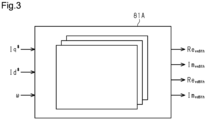
- the compensation calculator 81 uses a lookup table (LUT) 81A to obtain the amplitude Re vq6th of the cosine wave component and the amplitude Im vq6th of the sine wave component for the correction voltage Vqh and the amplitude Re vd6th of the cosine wave component and the amplitude Im vd6th of the sine wave component for the correction voltage Vdh.
- the lookup table 81A defines the relationship between input values and reference values.
- the input values include the absolute value of the q-axis current command value lq*, the absolute value of the d-axis current command value Id*, and the absolute value of the rotation speed ⁇ of the motor 21.
- the reference values include the amplitudes Re vq6th , Re vd6th of the cosine wave component and the amplitudes Im vq6th , Im vd6th of the sine wave component.
- the lookup table 81A is set, for example, through simulation performed by a device model. That is, first, through the simulation, for each set of the values of the q-axis current command value lq*, the d-axis current command value Id*, and the rotation speed ⁇ of the motor 21, the values of the amplitudes Re vq6th , Re vd6th of the cosine wave component and the amplitudes Im vq6th , Im vd6th of the sine wave component are collected. Then, the value collected through the simulation is stored in a sequence to set the lookup table 81A.
- the lookup table 81A refers to the q-axis current command value lq*, the d-axis current command value Id*, and the rotation speed ⁇ of the motor 21 as input values.
- the lookup table 81A outputs, as the reference values, the amplitude Re vq6th of the cosine wave component and the amplitude Im vq6th of the sine wave component for the correction voltage Vqh and the amplitude Re vd6th of the cosine wave component and the amplitude Im vd6th of the sine wave component for the correction voltage Vdh, which correspond to the absolute values of the input values.
- the compensation calculator 81 calculates the correction voltage Vqh by applying the amplitude Re vq6th of the cosine wave component and the amplitude Im vq6th of the sine wave component, which are obtained from the lookup table 81A, to the above equation (5). That is, the compensation calculator 81 synthesizes the correction voltage Vqh by adding together the real part (Re vq6th ⁇ cos6 ⁇ ), which is the cosine wave component, and the imaginary part (Im vq6th ⁇ sin6 ⁇ ), which is the sine wave component, at the same frequency.
- the compensation calculator 81 calculates the correction voltage Vdh by applying the amplitude Re vd6th of the cosine wave component and the amplitude Im vd6th of the sine wave component, which are obtained from the lookup table 81A, to the above equation (6). That is, the compensation calculator 81 synthesizes the correction voltage Vdh by adding together the real part (Re vd6th ⁇ cos6 ⁇ ), which is the cosine wave component, and the imaginary part (Im vd6th ⁇ sin6 ⁇ ), which is the sine wave component, at the same frequency.
- the adder 82 adds the correction voltage Vqh, which is calculated by the compensation calculator 81, to the q-axis voltage command value Vq*, which is calculated by the feedback controller 65, thereby calculating the final q-axis voltage command value Vqh*, which is used to control the motor 21.
- the final q-axis voltage command value Vqh* is expressed by the following equation (7).
- the adder 83 adds the correction voltage Vdh, which is calculated by the compensation calculator 81, to the d-axis voltage command value Vd*, which is calculated by the feedback controller 65, thereby calculating the final d-axis voltage command value Vdh*, which is used to control the motor 21.
- the final d-axis voltage command value Vdh* is expressed by the following equation (8).
- the compensation calculator 81 refers to the lookup table 81A to obtain the amplitude Re vq6th of the cosine wave component and the amplitude Im vq6th of the sine wave component for the correction voltage Vqh and the amplitude Re vd6th of the cosine wave component and the amplitude Im vd6th of the sine wave component for the correction voltage Vdh. This reduces the calculation load on the compensation calculator 81.
- the compensation calculator 81 needs to refer to only a single lookup table 81A. Thus, as compared to when reference is made to multiple lookup tables, the reference load on the lookup table is reduced.
- a phase lag occurs in the current in the motor coil. This is due to, for example, the inductance component of the motor coil, which is one reason why the current does not flow immediately even when a voltage is applied. Also, when the rotation speed ⁇ of the motor 21 increases, the phase lag relatively occurs. Thus, in order to drive the motor 21 with a higher efficiency, the phase of applied voltage needs to be advanced in anticipation of the phase lag of the current in the motor coil.
- the control device 40 may have the following configuration.
- the microcomputer 51 includes an advancement controller 84.
- the advancement controller 84 calculates an advancement value as a compensation value used to compensate for the phase lag of the current in the motor coil.
- the advancement controller 84 obtains the rotation angle ⁇ of the motor 21, which is detected by the rotation angle sensor 43, and calculates the advancement value based on the rotation speed ⁇ of the motor 21, which is obtained by differentiating the obtained rotation angle ⁇ with respect to time.
- the advancement controller 84 uses the advancement value to correct the rotation angle ⁇ of the motor 21.
- the advancement controller 84 calculates a final rotation angle ⁇ used to control the motor 21 by, for example, adding the advancement value to the rotation angle ⁇ of the motor 21, which is detected by the rotation angle sensor 43.
- the three-phase-to-two-phase coordinate converter 64 performs three-phase-to-two-phase coordinate conversion using the corrected rotation angle ⁇ , which is calculated by the advancement controller 84. Further, the two-phase-to-three-phase coordinate converter 66 performs two-phase-to-three-phase coordinate conversion using the corrected rotation angle ⁇ , which is calculated by the advancement controller 84.
- advancement occurs in the phase of the voltage applied to the motor 21 (i.e., the phases of the three-phase voltage command values Vu*, Vv*, Vw*) and consequently in the phase of the current in the motor coil.
- the phase of induced voltage generated in the motor coil matches the phase of the current in the motor coil to compensate for the rotational lag of the motor 21 and improve the response performance of the motor 21.
- the compensation calculator 81 uses the corrected rotation angle ⁇ , which is calculated by the advancement controller 84, to calculate the correction voltage Vqh for the q-axis current command value Iq* and the correction voltage Vdh for the d-axis current command value Id*.
- the process related to compensation control for torque ripple executed by the compensation calculator 81 is an example of a compensation calculation process.
- the present embodiment has the following advantages.
- the present embodiment may be modified as follows.
- the correction voltage Vqh may be added to only the q-axis voltage command value Vq* to execute the compensation control for torque ripple. That is, the correction voltage Vdh does not have to be added to the d-axis voltage command value Vd*. This is because the torque generated by the three-phase motor 21 has a greater influence on the q-axis current value Iq than the d-axis current value Id.
- the compensation control for torque ripple may reduce, for example, third or second harmonic components in the same manner as sixth harmonic components.
- the lookup table 81A may be configured to output reference values corresponding to a positive input value and a negative input value.
- the input values include the q-axis current command value Iq*, the d-axis current command value Id*, and the rotation speed ⁇ of the motor 21.
- the reference values include the amplitudes Re vq6th , Re vd6th of the cosine wave component and the amplitudes Im vq6th , Im vd6th of the sine wave component. This modification obtains advantages similar to advantages (3) and (4) of the above embodiment.
- the lookup table 81A may include multiple tables.
- the multiple tables simply need to include a table to be referred to when the q-axis current command value Iq*, the d-axis current command value Id*, and the rotation speed ⁇ of the motor 21 all have a positive value and a table to be referred to when the q-axis current command value Iq*, the d-axis current command value Id*, and the rotation speed ⁇ of the motor 21 all have a negative value.
- the number of the tables simply needs to correspond to a combination of positive and negative values of the q-axis current command value Iq*, the d-axis current command value Id*, and the rotation speed ⁇ of the motor 21.
- the number of poles and the number of slots of the motor 21 are changed in accordance with the product specification.
- the number of poles of the motor 21 may be ten, and the number of slots may be twelve. This reduces, for example, second harmonic components in the same manner as sixth harmonic components.
- the motor 21 may be an inter permanent magnet (IPM) motor.
- IPM motor is a motor with embedded magnets.
- permanent magnets are embedded, serving as the source of magnetic flux.
- the control device 40 may be arranged integrally with the motor 21.
- the control device 40 is arranged, for example, on an axial end of the motor 21.
- the control device 40 may be employed in an electric power steering system that applies an assist force to the steering shaft 13.
- the motor 21 is coupled to the steering shaft 13 by a transmission mechanism such as a worm speed reducer.
- the control device 40 may be used as a control device for a steer-by-wire system in which the power transmission path between the steering wheel 11 and the steerable wheels 12, 12 is mechanically cut off or can be mechanically cut off.
- a steer-by-wire system includes, for example, a system that is deployed to an autonomous driving system.
- the control device 40 is suitable as a control device for a reaction force motor that generates a steering reaction force applied to the steering wheel 11 or for a steering motor that generates a steering force, which is the power for steering the steerable wheels 12, 12.
Landscapes
- Engineering & Computer Science (AREA)
- Power Engineering (AREA)
- Chemical & Material Sciences (AREA)
- Combustion & Propulsion (AREA)
- Transportation (AREA)
- Mechanical Engineering (AREA)
- Control Of Ac Motors In General (AREA)
Abstract
Description
- The present disclosure relates to a motor control device and a motor control method.
- A conventional control device executes current feedback control that causes the value of an actual current supplied to a motor to follow a current command value. The motor is, for example, a three-phase brushless motor. The control device converts the detected values of three-phase currents supplied to the motor into those of two-phase currents in a dq-axis coordinate system, and performs current feedback control in the dq-axis coordinate system. Since the dq-axis coordinate system is a rotation coordinate system, the control device performs current vector control by dividing the currents into a torque component and a field-weakening component.
- Torque ripple, which is torque pulsation, may be generated in the motor. Torque ripple may result in vibration or noise. Thus, for example, a control device disclosed in Patent Literature 1 executes a compensation control that limits torque ripple. The control device superimposes, on a target q-axis current, a compensation current that cancels the torque ripple. The compensation current is a sine wave that is in antiphase with sixth harmonic components, which dominate the vibration components of the torque ripple.
- Patent Literature 1:
PCT Publication No. 2019/163552 - The control device of Patent Literature 1 calculates the gain (amplitude) and phase of the compensation current using a lookup table, based on the absolute value of the target q-axis current and the absolute value of the angular velocity of the motor. The control device calculates the compensation current using the gain and phase obtained from the lookup table. Thus, while the control device needs to calculate both gain and phase, there has been a recent desire to further reduce the calculation load on the control device.
- An aspect of the present disclosure provides a motor control device that calculates a voltage command value for an inverter by executing feedback control that causes a current value of a three-phase motor to follow a current command value for the motor. The inverter controls current supplied to the motor. The motor control device includes a compensation calculator configured to calculate, using a rotation angle of the motor detected by a sensor, a correction voltage added to the voltage command value to compensate for torque ripple of the motor. The correction voltage is a sine wave that is in antiphase with the torque ripple, and is obtained by adding together a real part that is a cosine wave component and an imaginary part that is a sine wave component. The cosine wave component and the sine wave component have the same frequency. The compensation calculator is configured to calculate an amplitude of the cosine wave component and an amplitude of the sine wave component from the current command value and a rotation speed of the motor.
- Another aspect of the present disclosure provides a motor control method that includes calculating a voltage command value for an inverter by executing feedback control that causes a current value of a three-phase motor to follow a current command value for the motor. The inverter controls current supplied to the motor. The motor control method further includes executing a compensation calculation process that calculates, using a rotation angle of the motor detected by a sensor, a correction voltage added to the voltage command value to compensate for torque ripple of the motor. The correction voltage is a sine wave that is in antiphase with the torque ripple, and is obtained by adding together a real part that is a cosine wave component and an imaginary part that is a sine wave component. The cosine wave component and the sine wave component having the same frequency. The compensation calculation process includes a process that calculates an amplitude of the cosine wave component and an amplitude of the sine wave component from the current command value and a rotation speed of the motor.
-
-
Fig. 1 is a diagram schematically showing an electric power steering system equipped with a motor control device according to an embodiment. -
Fig. 2 is a block diagram showing the motor control device of the embodiment. -
Fig. 3 is a block diagram illustrating a lookup table of the embodiment. - A motor control device according to an embodiment will now be described. The motor control device is used to control an electric power steering system.
- As shown in
Fig. 1 , an electricpower steering system 10 includes asteering shaft 13, apinion shaft 14, and asteerable wheel shaft 15. Thesteering shaft 13, thepinion shaft 14, and thesteerable wheel shaft 15 form a power transmission path between thesteering wheel 11 andsteerable wheels steerable wheel shaft 15 extends in the left-right direction inFig. 1 , which corresponds to the width direction of a vehicle body. Thesteerable wheel shaft 15 is accommodated in ahousing 16 that is fixed to the vehicle body. The opposite ends of thesteerable wheel shaft 15 are coupled to thesteerable wheels tie rods pinion shaft 14 includespinion teeth 14a that mesh withrack teeth 15a of thesteerable wheel shaft 15. Accordingly, when thesteerable wheel shaft 15 moves along its axis as thesteering wheel 11 rotates, steered angles θw, θw of thesteerable wheels - Further, the electric
power steering system 10 includes amotor 21 and atransmission mechanism 22. Themotor 21 and thetransmission mechanism 22 are each configured to apply an assist force to thesteerable wheel shaft 15. The assist force refers to the driving force applied to thesteering wheel 11 to assist the operation of thesteering wheel 11. - The
motor 21 is the source of the assist force. Themotor 21 is, for example, a three-phase brushless motor. Themotor 21 is fixed to the outside of thehousing 16. Themotor 21 includes anoutput shaft 21a that extends parallel to thesteerable wheel shaft 15. Theoutput shaft 21a of themotor 21 is coupled to thesteerable wheel shaft 15 by atransmission mechanism 22. The torque generated by themotor 21 is applied to thesteerable wheel shaft 15 by thetransmission mechanism 22 as the assist force. - The
transmission mechanism 22 includes aball nut 31, adriving pulley 32, a drivenpulley 33, and anendless belt 34. Theball nut 31 is fastened to a ball threadedpart 15b of thesteerable wheel shaft 15 by balls (not shown). Thedriving pulley 32 is fixed to theoutput shaft 21a of themotor 21. The drivenpulley 33 is fitted and fixed to the outer circumferential surface of theball nut 31. Thebelt 34 is looped between thedriving pulley 32 and the drivenpulley 33. Thus, rotation of themotor 21 is transmitted to theball nut 31 through thedriving pulley 32, thebelt 34, and the drivenpulley 33. As theball nut 31 rotates, thesteerable wheel shaft 15 moves along its axis. - Further, the electric
power steering system 10 includes acontrol device 40 that controls themotor 21. Thecontrol device 40 obtains the detection results of various types of vehicle on-board sensors as information indicating the request or traveling state of a driver, and controls themotor 21 based on the obtained information. Examples of the sensors include atorque sensor 41, a vehicle speed sensor 42, and arotation angle sensor 43. Thetorque sensor 41 is arranged on thesteering shaft 13. Thetorque sensor 41 detects a steering torque Th applied to the steeringshaft 13. The vehicle speed sensor 42 detects a vehicle speed V. Therotation angle sensor 43 is arranged in themotor 21. Therotation angle sensor 43 detects a rotation angle θ of themotor 21. By controlling the supply of power to themotor 21, thecontrol device 40 executes an assist control that generates the assist force corresponding to the steering torque Th and the vehicle speed V. Thecontrol device 40 performs vector control on themotor 21 using the rotation angle θ of themotor 21, which is detected by therotation angle sensor 43. - The
control device 40 will now be described in detail. - As shown in
Fig. 2 , thecontrol device 40 includes amicrocomputer 51 that generates a motor control signal and aninverter 52 that supplies three-phase driving power to themotor 21 based on a motor control signal generated by themicrocomputer 51. Themicrocomputer 51 is, for example, processing circuitry that includes a CPU and a memory. Themicrocomputer 51 executes various processes by causing the CPU to execute programs stored in the memory. The memory includes a computer-readable medium such as a random-access memory (RAM) or a read-only memory (ROM). However, using software to implement various processes is just one example. The processing circuitry of thecontrol device 40 may be configured to execute at least some of the processes using a hardware circuit, such as a logic circuit. - The
inverter 52 is a known PWM inverter. Theinverter 52 is formed by connecting three legs respectively corresponding to the three phases in parallel. Each leg includes two switching elements connected in series. Each switching element is, for example, an field-effect transistor (FET). The motor control signal generated by themicrocomputer 51 defines the duty cycle of each switching element of theinverter 52. The motor control signal is applied to a gate terminal of each switching element. In response to the motor control signal, the switching elements are turned on and off so that DC voltage of a vehicle on-board battery 53 is converted into driving power of three phases (U, V, W). As a result, the converted three-phase driving power is supplied to themotor 21. - The
microcomputer 51 obtains the steering torque Th, which is detected by thetorque sensor 41, the vehicle speed V, which is detected by the vehicle speed sensor 42, and the rotation angle θ of themotor 21, which is detected by therotation angle sensor 43. Further, themicrocomputer 51 receives the values of three-phase currents lu, Iv, Iw that are respectively detected bycurrent sensors motor 21. Themicrocomputer 51 controls the supply of power to themotor 21 based on the steering torque Th, the vehicle speed V, the rotation angle θ of themotor 21, and the values of the currents lu, Iv, Iw of themotor 21, which are detected by the respective sensors. Themicrocomputer 51 controls the supply of power to themotor 21 to obtain a proper assist force that corresponds to the operation state of thesteering wheel 11 or the traveling state of the vehicle. Themicrocomputer 51 controls themotor 21 through vector control that is described in a dq-axis coordinate system serving as a two-phase rotation coordinate system. - The configuration of the
microcomputer 51 will now be described in detail. - As shown in
Fig. 2 , themicrocomputer 51 includes arotation speed calculator 61, asteering angle calculator 62, a currentcommand value calculator 63, a three-phase-to-two-phase coordinateconverter 64, afeedback controller 65, a two-phase-to-three-phase coordinateconverter 66, and acontrol signal generator 67. - The
rotation speed calculator 61 is, for example, a differentiator. Therotation speed calculator 61 calculates a rotation speed ω of themotor 21 by differentiating the rotation angle θ of themotor 21, which is detected by therotation angle sensor 43, with respect to time. - The
steering angle calculator 62 calculates a steering angle θs from the rotation angle θ of themotor 21, which is detected by therotation angle sensor 43. The steering angle θs is the rotation angle of thesteering wheel 11. For example, thesteering angle calculator 62 calculates the absolute value of a rotation angle θ that exceeds 360° in multiple rotations by counting the number of the rotations of themotor 21 with reference to the neutral position of thesteering wheel 11 corresponding to a straight-line traveling state of the vehicle. Thesteering angle calculator 62 calculates the steering angle θs by multiplying the rotation angle θ of themotor 21 in multiple rotations by a conversion coefficient that is based on the deceleration ratio between themotor 21 and the steeringshaft 13. - The current
command value calculator 63 includes a q-axis current command value calculator 71 and a d-axis currentcommand value calculator 72.
The q-axis current command value calculator 71 calculates a basic assist torque from the steering torque Th, which is detected by thetorque sensor 41, and the vehicle speed V, which is detected by the vehicle speed sensor 42. The q-axis current command value calculator 71 calculates a target assist torque such that its absolute value increases as the absolute value of the steering torque Th increases and the vehicle speed V decreases. Further, the q-axis current command value calculator 71 uses the rotation speed ω of themotor 21, which is calculated by therotation speed calculator 61, and the steering angle θs, which is calculated by thesteering angle calculator 62, to calculate a compensation value for the basic assist torque. The compensation value is calculated as, for example, the sum of a force of the steeringshaft 13 returning to the neutral position and a return torque that corresponds to the resistance against the rotation of the steeringshaft 13. The returning force increases in proportion to the steering angle θs, and the return torque increases in proportion to the rotation speed ω of themotor 21. The q-axis current command value calculator 71 sets the target assist torque to the sum of the basic assist torque and the compensation value, and calculates a q-axis current command value Iq* in the dq-axis coordinate system by dividing the target assist torque by a torque constant. - The d-axis current
command value calculator 72 calculates a d-axis current command value Id* using the rotation speed ω of themotor 21, which is calculated by therotation speed calculator 61. The d-axis currentcommand value calculator 72 executes field-weakening control that sets the d-axis current command value Id* to a negative value based on the rotation speed ω of themotor 21. Specifically, as the rotation speed ω of themotor 21 increases, induced voltage (counter-electromotive force) produced in the motor coils of the three phases increases. Consequently, the rotation speed of themotor 21 has an upper limit (base speed). However, by setting the d-axis current command value Id* to a negative value, that is, by supplying a d-axis current in the negative direction, the magnetic flux in the d-axis direction is reduced using a demagnetization magnetomotive force produced by counter-acting on a d-axis armature, thereby reducing the induced voltage. This allows the driving range (rotation range) of themotor 21 to be extended beyond its base speed to a high-speed region. - For example, when the absolute value of the rotation speed ω is less than or equal to a first set value, which is a value relatively close to 0, the d-axis current
command value calculator 72 sets the d-axis current command value Id* to 0. When the absolute value of the rotation speed ω is greater than the first set value, the d-axis currentcommand value calculator 72 calculates a negative d-axis current command value Id*. When the absolute value of the rotation speed ω is greater than the first set value and less than or equal to a second set value, which is set to be greater than the first set value, the d-axis currentcommand value calculator 72 calculates the d-axis current command value Id* such that the d-axis current command value Id* has a larger absolute value as the absolute value of the rotation speed ω increases. When the absolute value of the rotation speed ω is greater than the second set value, the d-axis currentcommand value calculator 72 maintains the absolute value of the d-axis current command value Id* at an upper limit value. - The three-phase-to-two-phase coordinate
converter 64 obtains the rotation angle θ of themotor 21, which is detected by therotation angle sensor 43, and the values of currents lu, Iv, Iw of the phases of themotor 21, which are respectively detected by thecurrent sensors converter 64 uses the rotation angle θ of themotor 21 to convert the values of the three-phase currents lu, Iv, Iw of themotor 21 into a q-axis current value Iq and a d-axis current value Id of two-phase currents in the dq-axis coordinate system. - The
feedback controller 65 obtains the q-axis current command value Iq* and the d-axis current command value Id*, which are calculated by the currentcommand value calculator 63. Further, thefeedback controller 65 receives the q-axis current value Iq and the d-axis current value Id, which are calculated by the three-phase-to-two-phase coordinateconverter 64. Thefeedback controller 65 calculates a q-axis current deviation, which is the value of the difference between the q-axis current command value Iq* and the q-axis current value Iq, and a d-axis current deviation, which is the value of the difference between the d-axis current command value Id* and the d-axis current value Id. Thefeedback controller 65 calculates a q-axis voltage command value Vq* such that the q-axis current value Iq follows the q-axis current command value Iq*. Thefeedback controller 65 calculates a d-axis voltage command value Vd* such that the d-axis current value Id follows the d-axis current command value Id*. Thefeedback controller 65 calculates the q-axis voltage command value Vq* and the d-axis voltage command value Vd* by, for example, multiplying the q-axis current deviation and the d-axis current deviation by a predetermined feedback gain. - The two-phase-to-three-phase coordinate
converter 66 receives the q-axis voltage command value Vq* and the d-axis voltage command value Vd*, which are calculated by thefeedback controller 65. The two-phase-to-three-phase coordinateconverter 66 converts the q-axis voltage command value Vq* and the d-axis voltage command value Vd* into three-phase voltage command values Vu*, Vv*, Vw* based on the rotation angle θ of themotor 21, which is detected by therotation angle sensor 43. - The
control signal generator 67 receives the three-phase voltage command values Vu*, Vv*, Vw*, which are calculated by the two-phase-to-three-phase coordinateconverter 66. Thecontrol signal generator 67 generates motor control signals (PWM control signals) Du, Dv, Dw that have duty cycles corresponding to the voltage command values Vu*, Vv*, Vw*, respectively. When the switching elements of theinverter 52 are switched based on the motor control signals Du, Dv, Dw, the current corresponding to the target assist torque is supplied to themotor 21. - Further, for example, when the
steering wheel 11 is rotated faster and themotor 21 is rotated at a higher speed, a negative d-axis current flows through themotor 21 as a field-weakening control current. This limits the occurrence of a counter-electromotive force (induced voltage) in themotor 21. Thus, even when thesteering wheel 11 is operated at a relatively high speed, themotor 21 rotates accordingly in a favorable manner. This provides a favorable steering feel. - The electric
power steering system 10 may have the following problem. Themotor 21 may generate torque ripple, which is torque pulsation, and the torque ripple results in vibration or noise. For example, when the number of poles of themotor 21 is eight and the number of slots is twelve, sixth harmonic components included in vibration components of the torque ripple have a greater influence. To ensure the steering feel, the electricpower steering system 10 needs to reduce vibrations. To ensure quietness, the electricpower steering system 10 needs to reduce operating noises. Thus, thecontrol device 40 executes a compensation control that limits the torque ripple of themotor 21. - One example of the configuration of compensating for torque ripple is as follows.
As shown inFig. 2 , themicrocomputer 51 includes acompensation calculator 81 and twoadders - The
compensation calculator 81 receives the q-axis current command value Iq*, which is calculated by the q-axis current command value calculator 71, and the d-axis current command value Id*, which is calculated by the d-axis currentcommand value calculator 72. Further, thecompensation calculator 81 receives the rotation speed ω of themotor 21, which is calculated by therotation speed calculator 61, and the rotation angle θ of themotor 21, which is detected by therotation angle sensor 43. - Based on the q-axis current command value lq*, the rotation speed ω of the
motor 21, and the rotation angle θ of themotor 21, thecompensation calculator 81 calculates a correction voltage Vqh for the q-axis current command value lq* as a compensation value that is used to cancel the torque ripple. Further, thecompensation calculator 81 uses the d-axis current command value Id*, the rotation speed ω of themotor 21, and the rotation angle θ of themotor 21 to calculate a correction voltage Vdh for the d-axis current command value Id* as a compensation value that is used to cancel the torque ripple. The correction voltage Vqh, Vdh are sine waves that are in antiphase with sixth harmonic components, which dominate the vibration components of the torque ripple. - The correction voltage Vqh is expressed by the following equation (1).

motor 21 detected by therotation angle sensor 43. - The correction voltage Vdh is expressed by the following equation (2).

motor 21 detected by therotation angle sensor 43. - The
compensation calculator 81 may obtain the values of the amplitude Vqh6th and the phase θVqf6th with reference to, for example, a first lookup table. The first lookup table defines the relationship between input values and reference values. The input values include the absolute value of the q-axis current command value lq* and the absolute value of the rotation speed ω of themotor 21. The reference values include the amplitude Vqh6th and the phase θVqf6th. With reference to the first lookup table, in which the q-axis current command value lq* and the rotation speed ω of themotor 21 are input values, thecompensation calculator 81 obtains, as reference values, the amplitude Vqh6th and the phase θVqf6th, which correspond to the absolute values of the input values. Thecompensation calculator 81 calculates the correction voltage Vqh by applying the amplitude Vqh6th and the phase θVqf6th, which are obtained from the first lookup table, to the above equation (1). - The
compensation calculator 81 obtains the values of the amplitude Vdh6th and the phase θVdf6th with reference to a second lookup table. The second lookup table defines the relationship between input values and reference values. The input values include the absolute value of the d-axis current command value Id* and the absolute value of the rotation speed ω of themotor 21. The reference values include the amplitude Vdh6th and the phase θVdf6th. With reference to the second lookup table, in which the d-axis current command value Id* and the rotation speed ω of themotor 21 are input values, thecompensation calculator 81 obtains, as reference values, the amplitude Vdh6th and the phase θVdf6th, which correspond to the absolute values of the input values. Thecompensation calculator 81 calculates the correction voltage Vdh by applying the amplitude Vdh6th and the phase θVdf6th, which are obtained from the second lookup table, to the above equation (2). - The
adder 82 adds the correction voltage Vqh, which is calculated by thecompensation calculator 81, to the q-axis voltage command value Vq*, which is calculated by thefeedback controller 65, thereby calculating a final q-axis voltage command value Vqh* that is used to control themotor 21. The final q-axis voltage command value Vqh* is represented by the following equation (3).
adder 83 adds the correction voltage Vdh, which is calculated by thecompensation calculator 81, to the d-axis voltage command value Vd*, which is calculated by thefeedback controller 65, thereby calculating a final d-axis voltage command value Vdh* that is used to control themotor 21. The final d-axis voltage command value Vdh* is expressed by the following equation (4).
motor 21 is limited by adding the correction voltage Vqh, which cancels the torque ripple, to the q-axis voltage command value Vq* for theinverter 52 and adding the correction voltage Vdh, which cancels the torque ripple, to the d-axis voltage command value Vd* for theinverter 52. - In the compensation control for the torque ripple, for example, a correction current that cancels the torque ripple may be added to each of the q-axis current command value Iq* and the d-axis current command value Id*. However, in a case in which the correction current is superimposed on the current command value, the calculation cycle needs to be set to a shorter time as the current feedback is executed to cause the current command value to follow the actual current value. This further increases the calculation load. In this regard, in a case in which the correction voltage is superimposed on the voltage command value, the calculation cycle of the
microcomputer 51 is theoretically a cycle of superimposing the correction voltage on the voltage command value. Thus, the calculation load in this case is lower than the calculation load in the case in which the correction current is superimposed on the current command value. This allows themicrocomputer 51 to handle a high-frequency order component and handle a high-speed rotation of themotor 21 without setting the calculation cycle to a shorter time. - In recent years, the calculation load on the
microcomputer 51 needs to be further reduced. In this case, the correction voltages Vqh, Vdh may be calculated as follows. - First, the correction voltages Vqh, Vdh, which are sine waves, are each broken into a real part that is a cosine wave component and an imaginary part that is a sine wave component. In this case, the cosine wave component and the sine wave component have the same frequency.
The correction voltage Vqh is expressed by the following equation (5).
motor 21 detected by therotation angle sensor 43. - The correction voltage Vdh is expressed by the following equation (6).

motor 21 detected by therotation angle sensor 43. - The
compensation calculator 81 uses a lookup table (LUT) 81A to obtain the amplitude Revq6th of the cosine wave component and the amplitude Imvq6th of the sine wave component for the correction voltage Vqh and the amplitude Revd6th of the cosine wave component and the amplitude Imvd6th of the sine wave component for the correction voltage Vdh. The lookup table 81A defines the relationship between input values and reference values. The input values include the absolute value of the q-axis current command value lq*, the absolute value of the d-axis current command value Id*, and the absolute value of the rotation speed ω of themotor 21. The reference values include the amplitudes Revq6th, Revd6th of the cosine wave component and the amplitudes Imvq6th, Imvd6th of the sine wave component. - The lookup table 81A is set, for example, through simulation performed by a device model. That is, first, through the simulation, for each set of the values of the q-axis current command value lq*, the d-axis current command value Id*, and the rotation speed ω of the
motor 21, the values of the amplitudes Revq6th, Revd6th of the cosine wave component and the amplitudes Imvq6th, Imvd6th of the sine wave component are collected. Then, the value collected through the simulation is stored in a sequence to set the lookup table 81A. - As shown in
Fig. 3 , the lookup table 81A refers to the q-axis current command value lq*, the d-axis current command value Id*, and the rotation speed ω of themotor 21 as input values. The lookup table 81A outputs, as the reference values, the amplitude Revq6th of the cosine wave component and the amplitude Imvq6th of the sine wave component for the correction voltage Vqh and the amplitude Revd6th of the cosine wave component and the amplitude Imvd6th of the sine wave component for the correction voltage Vdh, which correspond to the absolute values of the input values. - The
compensation calculator 81 calculates the correction voltage Vqh by applying the amplitude Revq6th of the cosine wave component and the amplitude Imvq6th of the sine wave component, which are obtained from the lookup table 81A, to the above equation (5). That is, thecompensation calculator 81 synthesizes the correction voltage Vqh by adding together the real part (Revq6th · cos6θ), which is the cosine wave component, and the imaginary part (Imvq6th · sin6θ), which is the sine wave component, at the same frequency. Further, thecompensation calculator 81 calculates the correction voltage Vdh by applying the amplitude Revd6th of the cosine wave component and the amplitude Imvd6th of the sine wave component, which are obtained from the lookup table 81A, to the above equation (6). That is, thecompensation calculator 81 synthesizes the correction voltage Vdh by adding together the real part (Revd6th · cos6θ), which is the cosine wave component, and the imaginary part (Imvd6th · sin6θ), which is the sine wave component, at the same frequency. - The
adder 82 adds the correction voltage Vqh, which is calculated by thecompensation calculator 81, to the q-axis voltage command value Vq*, which is calculated by thefeedback controller 65, thereby calculating the final q-axis voltage command value Vqh*, which is used to control themotor 21. The final q-axis voltage command value Vqh* is expressed by the following equation (7).
adder 83 adds the correction voltage Vdh, which is calculated by thecompensation calculator 81, to the d-axis voltage command value Vd*, which is calculated by thefeedback controller 65, thereby calculating the final d-axis voltage command value Vdh*, which is used to control themotor 21. The final d-axis voltage command value Vdh* is expressed by the following equation (8).
compensation calculator 81 refers to the lookup table 81A to obtain the amplitude Revq6th of the cosine wave component and the amplitude Imvq6th of the sine wave component for the correction voltage Vqh and the amplitude Revd6th of the cosine wave component and the amplitude Imvd6th of the sine wave component for the correction voltage Vdh. This reduces the calculation load on thecompensation calculator 81. Thecompensation calculator 81 needs to refer to only a single lookup table 81A. Thus, as compared to when reference is made to multiple lookup tables, the reference load on the lookup table is reduced. - In general, a phase lag occurs in the current in the motor coil. This is due to, for example, the inductance component of the motor coil, which is one reason why the current does not flow immediately even when a voltage is applied. Also, when the rotation speed ω of the
motor 21 increases, the phase lag relatively occurs. Thus, in order to drive themotor 21 with a higher efficiency, the phase of applied voltage needs to be advanced in anticipation of the phase lag of the current in the motor coil. Thus, thecontrol device 40 may have the following configuration. - As indicated by the long dashed double-short dashed line in
Fig. 2 , themicrocomputer 51 includes anadvancement controller 84. Theadvancement controller 84 calculates an advancement value as a compensation value used to compensate for the phase lag of the current in the motor coil. Theadvancement controller 84, for example, obtains the rotation angle θ of themotor 21, which is detected by therotation angle sensor 43, and calculates the advancement value based on the rotation speed ω of themotor 21, which is obtained by differentiating the obtained rotation angle θ with respect to time. Theadvancement controller 84 uses the advancement value to correct the rotation angle θ of themotor 21. Theadvancement controller 84 calculates a final rotation angle θ used to control themotor 21 by, for example, adding the advancement value to the rotation angle θ of themotor 21, which is detected by therotation angle sensor 43. - The three-phase-to-two-phase coordinate
converter 64 performs three-phase-to-two-phase coordinate conversion using the corrected rotation angle θ, which is calculated by theadvancement controller 84. Further, the two-phase-to-three-phase coordinateconverter 66 performs two-phase-to-three-phase coordinate conversion using the corrected rotation angle θ, which is calculated by theadvancement controller 84. As a result, according to the advancement value calculated by theadvancement controller 84, advancement occurs in the phase of the voltage applied to the motor 21 (i.e., the phases of the three-phase voltage command values Vu*, Vv*, Vw*) and consequently in the phase of the current in the motor coil. The phase of induced voltage generated in the motor coil matches the phase of the current in the motor coil to compensate for the rotational lag of themotor 21 and improve the response performance of themotor 21. - The
compensation calculator 81 uses the corrected rotation angle θ, which is calculated by theadvancement controller 84, to calculate the correction voltage Vqh for the q-axis current command value Iq* and the correction voltage Vdh for the d-axis current command value Id*. In the present embodiment, the process related to compensation control for torque ripple executed by thecompensation calculator 81 is an example of a compensation calculation process. - The present embodiment has the following advantages.
- (1) The correction voltage Vqh, which is a sine wave, is divided into the real part (Revq6th · cos6θ), which is a cosine wave component, and the imaginary part (Imvq6th · sin6θ), which is a sine wave component, at the same frequency to simplify the calculation of the correction voltage Vqh. For example, if the amplitude Revq6th of the cosine wave component and the amplitude Imvq6th of the sine wave component are known, the correction voltage Vqh, which is a sine wave that is in antiphase with torque ripple, can be identified using the rotation angle θ of the
motor 21, which is detected by therotation angle sensor 43. Further, the phase of the correction voltage Vqh does not have to be calculated. In the same manner as the correction voltage Vqh, the correction voltage Vdh is divided into the real part (Revd6th · cos6θ), which is a cosine wave component, and the imaginary part (Imvd6th · sin6θ), which is a sine wave component, at the same frequency to simplify the calculation of the correction voltage Vdh. This reduces the calculation load. In such a manner, while the calculated correction voltage Vqh is applied to the q-axis voltage command value Vq*, the correction voltage Vdh is applied to the d-axis voltage command value Vd*. This limits the torque ripple of themotor 21. - (2) In the compensation control for the torque ripple, when the correction voltages Vqh, Vdh are respectively added to the q-axis voltage command value Vq* and the d-axis voltage command value Vd*, the calculation cycle of the
microcomputer 51 is theoretically a cycle of superimposing the correction voltage on the voltage command value. This reduces the calculation load as compared with when a correction current is added to each of the q-axis current command value Iq* and the d-axis current command value Id*. This allows themicrocomputer 51 to handle a high-frequency order component and handle a high-speed rotation of themotor 21 without setting the calculation cycle to a shorter time. - (3) By referring to a single lookup table 81A, the
compensation calculator 81 immediately obtains the parameters (Revq6th, Imvq6th, Revd6th, Imvd6th) required to calculate the correction voltage Vqh. This reduces the calculation load on thecompensation calculator 81. - (4) The
compensation calculator 81 needs to refer to only a single lookup table 81A. Thus, as compared to when reference is made to multiple lookup tables, the reference load on the lookup table is reduced. - (5) When the advancement control is performed to compensate for the rotation delay in the
motor 21, thecompensation calculator 81 calculates the correction voltages Vqh, Vdh using the corrected rotation angle θ, which is calculated by theadvancement controller 84, and the rotation speed ω, which is calculated based on the corrected rotation angle θ. Thecompensation calculator 81 uses the corrected rotation angle θ, which is the final rotation angle used to control themotor 21, to calculate more proper correction voltages Vqh, Vdh. Further, thecompensation calculator 81 obtains the corrected rotation angle θ and the rotation speed ω that is based on the corrected rotation angle θ. This reduces the calculation load on thecompensation calculator 81. - (6) Since the torque ripple of the
motor 21 is limited, generation of vibration or noise is limited. Thus, thecontrol device 40 is suitable for the electricpower steering system 10, which requires quietness. - The present embodiment may be modified as follows.
- Depending on product specifications, the correction voltage Vqh may be added to only the q-axis voltage command value Vq* to execute the compensation control for torque ripple. That is, the correction voltage Vdh does not have to be added to the d-axis voltage command value Vd*. This is because the torque generated by the three-
phase motor 21 has a greater influence on the q-axis current value Iq than the d-axis current value Id. - The compensation control for torque ripple may reduce, for example, third or second harmonic components in the same manner as sixth harmonic components. The lookup table 81A may be configured to output reference values corresponding to a positive input value and a negative input value. In this case, the input values include the q-axis current command value Iq*, the d-axis current command value Id*, and the rotation speed ω of the
motor 21. The reference values include the amplitudes Revq6th, Revd6th of the cosine wave component and the amplitudes Imvq6th, Imvd6th of the sine wave component. This modification obtains advantages similar to advantages (3) and (4) of the above embodiment. - The lookup table 81A may include multiple tables. For example, the multiple tables simply need to include a table to be referred to when the q-axis current command value Iq*, the d-axis current command value Id*, and the rotation speed ω of the
motor 21 all have a positive value and a table to be referred to when the q-axis current command value Iq*, the d-axis current command value Id*, and the rotation speed ω of themotor 21 all have a negative value. For example, the number of the tables simply needs to correspond to a combination of positive and negative values of the q-axis current command value Iq*, the d-axis current command value Id*, and the rotation speed ω of themotor 21. - The number of poles and the number of slots of the
motor 21 are changed in accordance with the product specification. For example, the number of poles of themotor 21 may be ten, and the number of slots may be twelve. This reduces, for example, second harmonic components in the same manner as sixth harmonic components. - The
motor 21 may be an inter permanent magnet (IPM) motor. The IPM motor is a motor with embedded magnets. In the rotor of the IPM motor, permanent magnets are embedded, serving as the source of magnetic flux. - The
control device 40 may be arranged integrally with themotor 21. Thecontrol device 40 is arranged, for example, on an axial end of themotor 21. - The
control device 40 may be employed in an electric power steering system that applies an assist force to the steeringshaft 13. In this case, as shown by the long dashed double-short dashed line inFig. 1 , themotor 21 is coupled to the steeringshaft 13 by a transmission mechanism such as a worm speed reducer. - The
control device 40 may be used as a control device for a steer-by-wire system in which the power transmission path between thesteering wheel 11 and thesteerable wheels control device 40 is suitable as a control device for a reaction force motor that generates a steering reaction force applied to thesteering wheel 11 or for a steering motor that generates a steering force, which is the power for steering thesteerable wheels
Claims (6)
- A motor control device that calculates a voltage command value for an inverter by executing feedback control that causes a current value of a three-phase motor to follow a current command value for the motor, the inverter controlling current supplied to the motor, the motor control device comprising:a compensation calculator configured to calculate, using a rotation angle of the motor detected by a sensor, a correction voltage added to the voltage command value to compensate for torque ripple of the motor, whereinthe correction voltage is a sine wave that is in antiphase with the torque ripple, and is obtained by adding together a real part that is a cosine wave component and an imaginary part that is a sine wave component, the cosine wave component and the sine wave component having the same frequency, andthe compensation calculator is configured to calculate an amplitude of the cosine wave component and an amplitude of the sine wave component from the current command value and a rotation speed of the motor.
- The motor control device according to claim 1, whereinthe compensation calculator is configured to calculate the amplitude of the cosine wave component and the amplitude of the sine wave component with reference to a single lookup table,the lookup table defines a relationship between an input value and a reference value,the input value includes the current command value and the rotation speed of the motor, andthe reference value includes the amplitude of the cosine wave component and the amplitude of the sine wave component.
- The motor control device according to claim 1 or 2, whereinthe current command value includes a d-axis current command value and a q-axis current command value in a dq-axis coordinate system,the voltage command value includes a d-axis voltage command value and a q-axis voltage command value that are calculated by executing feedback control that causes a d-axis current value and a q-axis current value to respectively follow the d-axis current command value and the q-axis current command value,the d-axis current value and the q-axis current value are obtained through coordinate conversion of three-phase current values of the motor into two-phase current values in the dq-axis coordinate system, andthe compensation calculator is configured to calculate the correction voltage for each of the q-axis voltage command value and the d-axis voltage command value based on the d-axis current command value, the q-axis current command value, and the rotation speed of the motor.
- The motor control device according to any one of claims 1 to 3, comprising an advancement controller configured to correct the rotation angle of the motor detected by the sensor, based on the rotation speed of the motor, to compensate for a phase lag of current in a motor coil, wherein
the compensation calculator is configured to calculate the correction voltage using the rotation angle of the motor subsequent to being corrected by the advancement controller. - The motor control device according to any one of claims 1 to 4, wherein the motor is configured to generate a driving force applied to a steering wheel of a vehicle.
- A motor control method, comprising:calculating a voltage command value for an inverter by executing feedback control that causes a current value of a three-phase motor to follow a current command value for the motor, the inverter controlling current supplied to the motor;executing a compensation calculation process that calculates, using a rotation angle of the motor detected by a sensor, a correction voltage added to the voltage command value to compensate for torque ripple of the motor, whereinthe correction voltage is a sine wave that is in antiphase with the torque ripple, and is obtained by adding together a real part that is a cosine wave component and an imaginary part that is a sine wave component, the cosine wave component and the sine wave component having the same frequency, andthe compensation calculation process includes a process that calculates an amplitude of the cosine wave component and an amplitude of the sine wave component from the current command value and a rotation speed of the motor.
Applications Claiming Priority (2)
| Application Number | Priority Date | Filing Date | Title |
|---|---|---|---|
| JP2021071707 | 2021-04-21 | ||
| PCT/JP2022/015406 WO2022224736A1 (en) | 2021-04-21 | 2022-03-29 | Motor control device, and motor control method |
Publications (2)
| Publication Number | Publication Date |
|---|---|
| EP4329187A1 true EP4329187A1 (en) | 2024-02-28 |
| EP4329187A4 EP4329187A4 (en) | 2024-10-16 |
Family
ID=83722090
Family Applications (1)
| Application Number | Title | Priority Date | Filing Date |
|---|---|---|---|
| EP22791511.3A Pending EP4329187A4 (en) | 2021-04-21 | 2022-03-29 | ENGINE CONTROL DEVICE AND ENGINE CONTROL METHOD |
Country Status (5)
| Country | Link |
|---|---|
| US (1) | US12375017B2 (en) |
| EP (1) | EP4329187A4 (en) |
| JP (1) | JPWO2022224736A1 (en) |
| CN (1) | CN117178471A (en) |
| WO (1) | WO2022224736A1 (en) |
Families Citing this family (2)
| Publication number | Priority date | Publication date | Assignee | Title |
|---|---|---|---|---|
| JP7374813B2 (en) * | 2020-02-28 | 2023-11-07 | サンデン株式会社 | motor control device |
| JP7550098B2 (en) * | 2021-04-06 | 2024-09-12 | 株式会社デンソー | MOTOR CONTROL DEVICE AND STEERING SYSTEM INCLUDING THE SAME |
Family Cites Families (10)
| Publication number | Priority date | Publication date | Assignee | Title |
|---|---|---|---|---|
| JP3576023B2 (en) * | 1999-02-12 | 2004-10-13 | シャープ株式会社 | Motor speed control device |
| JP2005102434A (en) * | 2003-09-25 | 2005-04-14 | Mitsubishi Heavy Ind Ltd | Control unit for motor |
| JP4561105B2 (en) * | 2004-01-21 | 2010-10-13 | 株式会社ジェイテクト | Motor control device |
| JP5313553B2 (en) * | 2008-06-09 | 2013-10-09 | 三菱電機株式会社 | Electric power steering control device |
| US9257931B2 (en) * | 2011-01-18 | 2016-02-09 | Daikin Industries, Ltd. | Power conversion apparatus |
| JP5532115B1 (en) * | 2012-12-07 | 2014-06-25 | 株式会社明電舎 | Periodic disturbance automatic suppression device |
| US9136785B2 (en) * | 2013-03-12 | 2015-09-15 | Steering Solutions Ip Holding Corporation | Motor control system to compensate for torque ripple |
| US9160260B1 (en) * | 2014-06-16 | 2015-10-13 | Moog Inc. | Adaptive actuator control system |
| WO2016067665A1 (en) * | 2014-10-30 | 2016-05-06 | 三菱電機株式会社 | Inverter control device and inverter compressor |
| JPWO2019163552A1 (en) * | 2018-02-20 | 2021-03-04 | 日本電産株式会社 | Motor control system and power steering system |
-
2022
- 2022-03-29 EP EP22791511.3A patent/EP4329187A4/en active Pending
- 2022-03-29 JP JP2023516382A patent/JPWO2022224736A1/ja active Pending
- 2022-03-29 WO PCT/JP2022/015406 patent/WO2022224736A1/en not_active Ceased
- 2022-03-29 US US18/286,236 patent/US12375017B2/en active Active
- 2022-03-29 CN CN202280029050.5A patent/CN117178471A/en active Pending
Also Published As
| Publication number | Publication date |
|---|---|
| JPWO2022224736A1 (en) | 2022-10-27 |
| WO2022224736A1 (en) | 2022-10-27 |
| US12375017B2 (en) | 2025-07-29 |
| US20240372493A1 (en) | 2024-11-07 |
| EP4329187A4 (en) | 2024-10-16 |
| CN117178471A (en) | 2023-12-05 |
Similar Documents
| Publication | Publication Date | Title |
|---|---|---|
| US7843154B2 (en) | Motor controller and electric power steering apparatus | |
| US8686672B2 (en) | Motor control device and electric power steering device | |
| US8952637B2 (en) | Control device for three-phase rotating machine | |
| US9979340B2 (en) | Apparatus for controlling three phase rotary electric machine reducing peak value of phase current | |
| EP1470988B2 (en) | Electric power steering apparatus | |
| EP2398142B1 (en) | Motor control device and electric power steering device | |
| US20110231066A1 (en) | Electric power steering apparatus and electric motor driving controller used for the apparatus | |
| JP4715919B2 (en) | Electric power steering device | |
| US7913805B2 (en) | Electric power steering apparatus | |
| CN102687385A (en) | Electric Power Steering | |
| CN110809855B (en) | Motor control device and electric power steering device equipped with same | |
| WO2011077589A1 (en) | Electric power steering apparatus | |
| US6810986B2 (en) | Electric power steering apparatus and control method therefor | |
| US8354810B2 (en) | Electric power steering device | |
| EP1634797B1 (en) | Motor controller and electric power steering apparatus | |
| EP3300245B1 (en) | Motor control device | |
| JP2016111788A (en) | Control device for rotary electric machine | |
| JP4603340B2 (en) | Motor control device and steering device | |
| WO2008015856A1 (en) | Electric power steering system | |
| JP2012166776A (en) | Electric power steering device | |
| US12375017B2 (en) | Motor control device, and motor control method | |
| EP1722469A1 (en) | Motor-driven power steering device control device | |
| JP2011230531A (en) | Device for controlling motor | |
| JP5683417B2 (en) | Electric power steering device | |
| JP2009284728A (en) | Motor control apparatus and electric power-steering arrangement |
Legal Events
| Date | Code | Title | Description |
|---|---|---|---|
| STAA | Information on the status of an ep patent application or granted ep patent |
Free format text: STATUS: THE INTERNATIONAL PUBLICATION HAS BEEN MADE |
|
| PUAI | Public reference made under article 153(3) epc to a published international application that has entered the european phase |
Free format text: ORIGINAL CODE: 0009012 |
|
| STAA | Information on the status of an ep patent application or granted ep patent |
Free format text: STATUS: REQUEST FOR EXAMINATION WAS MADE |
|
| 17P | Request for examination filed |
Effective date: 20231114 |
|
| AK | Designated contracting states |
Kind code of ref document: A1 Designated state(s): AL AT BE BG CH CY CZ DE DK EE ES FI FR GB GR HR HU IE IS IT LI LT LU LV MC MK MT NL NO PL PT RO RS SE SI SK SM TR |
|
| DAV | Request for validation of the european patent (deleted) | ||
| DAX | Request for extension of the european patent (deleted) | ||
| A4 | Supplementary search report drawn up and despatched |
Effective date: 20240917 |
|
| RIC1 | Information provided on ipc code assigned before grant |
Ipc: B62D 5/04 20060101ALI20240911BHEP Ipc: H02P 21/22 20160101ALI20240911BHEP Ipc: H02P 21/05 20060101AFI20240911BHEP |
|
| STAA | Information on the status of an ep patent application or granted ep patent |
Free format text: STATUS: EXAMINATION IS IN PROGRESS |
|
| 17Q | First examination report despatched |
Effective date: 20260210 |