EP4329159A1 - Electric power unit and straddled vehicle having the same - Google Patents
Electric power unit and straddled vehicle having the same Download PDFInfo
- Publication number
- EP4329159A1 EP4329159A1 EP23161421.5A EP23161421A EP4329159A1 EP 4329159 A1 EP4329159 A1 EP 4329159A1 EP 23161421 A EP23161421 A EP 23161421A EP 4329159 A1 EP4329159 A1 EP 4329159A1
- Authority
- EP
- European Patent Office
- Prior art keywords
- rotor
- motor
- shaft
- electric
- output shaft
- Prior art date
- Legal status (The legal status is an assumption and is not a legal conclusion. Google has not performed a legal analysis and makes no representation as to the accuracy of the status listed.)
- Withdrawn
Links
Images


Classifications
-
- B—PERFORMING OPERATIONS; TRANSPORTING
- B62—LAND VEHICLES FOR TRAVELLING OTHERWISE THAN ON RAILS
- B62M—RIDER PROPULSION OF WHEELED VEHICLES OR SLEDGES; POWERED PROPULSION OF SLEDGES OR SINGLE-TRACK CYCLES; TRANSMISSIONS SPECIALLY ADAPTED FOR SUCH VEHICLES
- B62M7/00—Motorcycles characterised by position of motor or engine
- B62M7/02—Motorcycles characterised by position of motor or engine with engine between front and rear wheels
-
- B—PERFORMING OPERATIONS; TRANSPORTING
- B60—VEHICLES IN GENERAL
- B60L—PROPULSION OF ELECTRICALLY-PROPELLED VEHICLES; SUPPLYING ELECTRIC POWER FOR AUXILIARY EQUIPMENT OF ELECTRICALLY-PROPELLED VEHICLES; ELECTRODYNAMIC BRAKE SYSTEMS FOR VEHICLES IN GENERAL; MAGNETIC SUSPENSION OR LEVITATION FOR VEHICLES; MONITORING OPERATING VARIABLES OF ELECTRICALLY-PROPELLED VEHICLES; ELECTRIC SAFETY DEVICES FOR ELECTRICALLY-PROPELLED VEHICLES
- B60L15/00—Methods, circuits, or devices for controlling the traction-motor speed of electrically-propelled vehicles
- B60L15/20—Methods, circuits, or devices for controlling the traction-motor speed of electrically-propelled vehicles for control of the vehicle or its driving motor to achieve a desired performance, e.g. speed, torque, programmed variation of speed
-
- B—PERFORMING OPERATIONS; TRANSPORTING
- B62—LAND VEHICLES FOR TRAVELLING OTHERWISE THAN ON RAILS
- B62M—RIDER PROPULSION OF WHEELED VEHICLES OR SLEDGES; POWERED PROPULSION OF SLEDGES OR SINGLE-TRACK CYCLES; TRANSMISSIONS SPECIALLY ADAPTED FOR SUCH VEHICLES
- B62M21/00—Transmissions characterised by use of resilient elements therein
-
- F—MECHANICAL ENGINEERING; LIGHTING; HEATING; WEAPONS; BLASTING
- F16—ENGINEERING ELEMENTS AND UNITS; GENERAL MEASURES FOR PRODUCING AND MAINTAINING EFFECTIVE FUNCTIONING OF MACHINES OR INSTALLATIONS; THERMAL INSULATION IN GENERAL
- F16D—COUPLINGS FOR TRANSMITTING ROTATION; CLUTCHES; BRAKES
- F16D3/00—Yielding couplings, i.e. with means permitting movement between the connected parts during the drive
- F16D3/02—Yielding couplings, i.e. with means permitting movement between the connected parts during the drive adapted to specific functions
- F16D3/12—Yielding couplings, i.e. with means permitting movement between the connected parts during the drive adapted to specific functions specially adapted for accumulation of energy to absorb shocks or vibration
-
- H—ELECTRICITY
- H02—GENERATION; CONVERSION OR DISTRIBUTION OF ELECTRIC POWER
- H02K—DYNAMO-ELECTRIC MACHINES
- H02K7/00—Arrangements for handling mechanical energy structurally associated with dynamo-electric machines, e.g. structural association with mechanical driving motors or auxiliary dynamo-electric machines
- H02K7/14—Structural association with mechanical loads, e.g. with hand-held machine tools or fans
-
- B—PERFORMING OPERATIONS; TRANSPORTING
- B60—VEHICLES IN GENERAL
- B60L—PROPULSION OF ELECTRICALLY-PROPELLED VEHICLES; SUPPLYING ELECTRIC POWER FOR AUXILIARY EQUIPMENT OF ELECTRICALLY-PROPELLED VEHICLES; ELECTRODYNAMIC BRAKE SYSTEMS FOR VEHICLES IN GENERAL; MAGNETIC SUSPENSION OR LEVITATION FOR VEHICLES; MONITORING OPERATING VARIABLES OF ELECTRICALLY-PROPELLED VEHICLES; ELECTRIC SAFETY DEVICES FOR ELECTRICALLY-PROPELLED VEHICLES
- B60L2200/00—Type of vehicles
- B60L2200/12—Bikes
-
- B—PERFORMING OPERATIONS; TRANSPORTING
- B62—LAND VEHICLES FOR TRAVELLING OTHERWISE THAN ON RAILS
- B62K—CYCLES; CYCLE FRAMES; CYCLE STEERING DEVICES; RIDER-OPERATED TERMINAL CONTROLS SPECIALLY ADAPTED FOR CYCLES; CYCLE AXLE SUSPENSIONS; CYCLE SIDECARS, FORECARS, OR THE LIKE
- B62K2204/00—Adaptations for driving cycles by electric motor
-
- F—MECHANICAL ENGINEERING; LIGHTING; HEATING; WEAPONS; BLASTING
- F16—ENGINEERING ELEMENTS AND UNITS; GENERAL MEASURES FOR PRODUCING AND MAINTAINING EFFECTIVE FUNCTIONING OF MACHINES OR INSTALLATIONS; THERMAL INSULATION IN GENERAL
- F16D—COUPLINGS FOR TRANSMITTING ROTATION; CLUTCHES; BRAKES
- F16D2300/00—Special features for couplings or clutches
- F16D2300/22—Vibration damping
Definitions
- the present invention relates to an electric power unit and a straddled vehicle having the same.
- Straddled vehicles have been known in the art that have an electric motor as a driving source for driving. Electric motors are easier to control than internal combustion engines. A clutch and a transmission are necessary for a straddled vehicle having an internal combustion engine, whereas a clutch and a transmission can be omitted for a straddled vehicle having an electric motor (hereinafter referred to as an electric vehicle).
- JP 2019-155986A proposes to provide a clutch and an energy-storing rotor in an electric vehicle for the purpose of improving the controllability of the electric vehicle.
- the provision of the clutch improves the operating feel for the rider.
- the electric vehicle can store energy by disengaging the clutch and rotating the energy-storing rotor. For example, by engaging the clutch when starting, the energy stored in the energy-storing rotor can be transmitted to the drive wheel in addition to the driving force of the electric motor. Therefore, a large force can be applied to the drive wheel instantaneously.
- the present invention has been made in view of the above, and an object thereof is to provide a relatively small electric power unit and a straddled vehicle having the same, with which it is possible to improve the operating feel for the rider.
- An electric power unit disclosed herein includes an electric motor having a motor shaft, an output shaft for outputting power, a first power transmission mechanism connected to the motor shaft and the output shaft for transmitting power of the motor shaft to the output shaft, and a damper provided in the first power transmission mechanism.
- the damper produces play in the first power transmission mechanism, the rider is less likely to feel rigid operating feel. Thus, it is possible to improve the operating feel for the rider.
- the rider performs an operation so that the torque of the electric motor increases rapidly when starting or accelerating, part of the energy output by the electric motor is temporarily stored in the damper and then released toward the output shaft. Therefore, even without the energy-storing rotor, it is possible to output a large driving force instantaneously from the output shaft.
- the electric power unit described above there is no need for an energy-storing rotor and a clutch, and it is possible to reduce the size of the electric power unit.
- the damper may be a torsion damper including: a first rotor; a second rotor arranged coaxial with the first rotor; and a spring that is interposed between the first rotor and the second rotor and transmits a torque of the first rotor to the second rotor.
- the electric power unit may include an idle shaft that is parallel to the motor shaft and/or the output shaft.
- the first rotor and the second rotor may be supported on the idle shaft.
- the installation of the torsion damper is unlikely to be constrained by the position of the motor shaft and the output shaft. It is possible to increase the degree of freedom in installation of the torsion damper.
- the first rotor and the second rotor may be supported on the motor shaft.
- the first rotor and the second rotor may be supported on the output shaft.
- the electric power unit may include a control unit that controls the electric motor so that a torque of the electric motor changes periodically while a steady drive signal is received.
- a damper is provided in the first power transmission mechanism, and the damper has a natural period. If the control unit performs a control so that the fluctuation period of the torque of the electric motor is made to be equal to or closer to the natural period, it is possible to produce resonance. By using the resonance, it is possible to output a large driving force.
- the control unit may be configured to control the electric motor so that the fluctuation period of the torque of the electric motor is a predetermined set period based on the natural period of the damper.
- the electric power unit may include a control unit that, when starting to drive the electric motor, controls the electric motor so as to temporarily generate a torque in a reverse direction and then generate a torque in a forward direction on the electric motor.
- the electric power unit may include a control unit that, when a command to increase a torque of the electric motor is received while the electric motor is running, controls the electric motor so as to temporarily decrease and then increase the torque of the electric motor.
- the electric power unit may include another damper provided in the first power transmission mechanism.
- a straddled vehicle disclosed herein includes: an electric power unit described above; a drive wheel that is driven by power of the electric motor; and a second power transmission mechanism that connects together the output shaft and the drive wheel.
- the output shaft may include a connecting portion connected to the second power transmission mechanism.
- the connecting portion may be arranged on one side in an axial direction of the motor shaft relative to a middle position of the motor shaft in the axial direction; and the damper may be arranged on the other side in the axial direction relative to the middle position of the motor shaft in the axial direction.
- the output shaft may include a connecting portion connected to the second power transmission mechanism.
- the connecting portion and the damper may be arranged on one side in an axial direction of the motor shaft relative to a middle position of the motor shaft in the axial direction.
- the straddled vehicle may be an off-road motorcycle.
- Off-road motorcycles as compared to on-road motorcycles, tend to be required to instantaneously output a larger driving force from the electric power unit to the drive wheel when starting or accelerating. Therefore, the effects described above are particularly useful.
- FIG. 1 one embodiment of a straddled vehicle to be described below is an off-road motorcycle 1.
- the motorcycle 1 is a motocrosser.
- front, rear, left, right, up and down refer to these directions as viewed from a virtual rider seated on a seat 2 while the motorcycle 1 is standing upright on a horizontal surface with no rider and no load thereon, unless specified otherwise.
- the motorcycle 1 includes a seat 2, a handle 3, an electric power unit 5, a front wheel 4, a rear wheel 6, and a chain 7 linking the electric power unit 5 and the rear wheel 6.
- the rear wheel 6 is a drive wheel driven by the power of the electric power unit 5.
- the motorcycle 1 includes a control unit 10 that controls the electric power unit 5.
- the electric power unit 5 includes an electric motor (hereinafter referred to simply as motor) 12 having a motor shaft 11, and a battery 9.
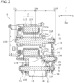
- FIG. 2 is a cross-sectional view of the electric power unit 5.
- the electric power unit 5 includes an output shaft 13 that outputs power, a power transmission mechanism 15 that transmits the power of the motor shaft 11 to the output shaft 13, and a torsion damper 20 provided in the power transmission mechanism 15.
- the motor 12 includes a rotor 12R fixed to the motor shaft 11 and a stator 12S arranged around the rotor 12R.
- the motor shaft 11 extends in the left-right direction of the vehicle.
- the motor shaft 11 is rotatably supported on a bearing 16A and a bearing 16B.
- the power transmission mechanism 15 is an example of the "first power transmission mechanism".
- the power transmission mechanism 15 is a mechanism that transmits power by a plurality of gears. Note however that the power transmission mechanism 15 only needs to be a mechanism that transmits the power of the motor shaft 11 to the output shaft 13, and there is no particular limitation on its specific configuration.
- the power transmission mechanism 15 is connected to the motor shaft 11 and the output shaft 13.
- the power transmission mechanism 15 includes a gear 31 fixed to the motor shaft 11, a gear 24 meshing with the gear 31, a torsion damper 20 provided with the gear 24, an idle shaft 14 supporting the torsion damper 20, a gear 34 formed on the idle shaft 14, and a gear 33 meshing with the gear 34.
- the gear 33 is fixed to the output shaft 13.
- the idle shaft 14 is rotatably supported on a bearing 17A and a bearing 17B.
- the idle shaft 14 is arranged parallel to the motor shaft 11.
- the idle shaft 14 extends in the left-right direction of the vehicle.
- the output shaft 13 is rotatably supported on a bearing 18A and a bearing 18B.
- the output shaft 13 is arranged parallel to the motor shaft 11.
- the output shaft 13 extends in the left-right direction of the vehicle.
- the gear 33 is fixed to the right end of the output shaft 13.
- a sprocket 19 is fixed to the left end of the output shaft 13.
- a chain 7 (see FIG. 1 ) is wound around the sprocket 19.
- the chain 7 is an example of the "second power transmission mechanism” connecting together the output shaft 13 and the rear wheel 6, which is the drive wheel.
- the sprocket 19 is an example of the "connecting portion” connected to the second power transmission mechanism of the output shaft 13.
- the chain 7 transmits the power of the output shaft 13 to the rear wheel 6.
- the second power transmission mechanism is not limited to the chain 7.
- the second power transmission mechanism may include, for example, a transmission belt or a drive shaft.
- FIG. 3 is a front view of the torsion damper 20, as viewed from the left side of the motorcycle 1.
- the torsion damper 20 includes a first rotor 21, a second rotor 22 and a spring 23.
- the first rotor 21 and the second rotor 22 are supported on the idle shaft 14.
- the second rotor 22 is arranged coaxial with the first rotor 21.
- the idle shaft 14 is provided with a bearing 25, and the first rotor 21 is rotatably supported on the bearing 25.
- the first rotor 21 is rotatable about the idle shaft 14.
- the second rotor 22 is not rotatable about the idle shaft 14.
- the second rotor 22 is configured to rotate together with the idle shaft 14.
- the first rotor 21 has a long hole 21a formed therein.
- the second rotor 22 has a pin 22a inserted into the long hole 21a.
- the second rotor 22 is rotatable relative to the first rotor 21. As the pin 22a contacts the edge of the long hole 21a, the rotation of the second rotor 22 relative to the first rotor 21 is regulated.
- the second rotor 22 is rotatable relative to the first rotor 21 until the pin 22a contacts the edge of the long hole 21a.
- the second rotor 22 is configured to be rotatable relative to the first rotor 21 by a predetermined angle. Note that the number of long holes 21a and pins 22a is 3 in the present embodiment, but there is no particular limitation thereto.
- the spring 23 is interposed between the first rotor 21 and the second rotor 22.
- the spring 23 is arranged between the first rotor 21 and the second rotor 22 on the path of power transmission.
- the spring 23 transmits the torque of the first rotor 21 to the second rotor 22.
- the spring 23 is a coil spring, and the number of springs 23 is 3, but there is no particular limitation on the form and the number of springs 23.
- the gear 24 is formed on the first rotor 21.
- the gear 24 and the first rotor 21 are an integral piece.
- the gear 24 may be formed separately from the first rotor 21.
- reference sign 11L denotes a straight line that indicates the left end position of the motor shaft 11
- reference sign 11R denotes a straight line that indicates the right end position of the motor shaft 11.
- Reference sign 11M denotes a straight line that indicates the middle position between the left end and the right end of the motor shaft 11. In other words, reference sign 11M denotes the middle position of the motor shaft 11 in the axial direction.
- the sprocket 19 is arranged on one side in the axial direction relative to the middle position 11M of the motor shaft 11 in the axial direction
- the torsion damper 20 is arranged on the other side in the axial direction relative to the middle position 11M of the motor shaft 11 in the axial direction.
- the sprocket 19 is arranged leftward relative to the middle position 11M of the motor shaft 11, and the torsion damper 20 is arranged rightward relative to the middle position 11M of the motor shaft 11. Note however that the sprocket 19 may be arranged rightward relative to the middle position 11M of the motor shaft 11, and the torsion damper 20 may be arranged leftward relative to the middle position 11M of the motor shaft 11.
- the electric power unit 5 and the motorcycle 1 are configured as described above. Next, the various effects brought about by the electric power unit 5 and the motorcycle 1 will be described.
- the torsion damper 20 is provided in the power transmission mechanism 15 that transmits the power of the motor shaft 11 to the output shaft 13. Since the torsion damper 20 produces play in the power transmission mechanism 15, the rider is less likely to feel a rigid operating feel. Thus, it is possible to improve the operating feel for the rider.
- the impact generated on the rear wheel 6 may be transmitted to the electric power unit 5.
- the impact transmitted to the output shaft 13 is absorbed by the torsion damper 20. Therefore, it is possible to mitigate the impact applied on the motor 12. It is possible to desirably protect the motor 12 from the impact from the road surface.
- the damper provided in the power transmission mechanism 15 is not limited to the torsion damper 20. Note however that if the torsion damper 20 is used as the damper of the power transmission mechanism 15, it is possible to relatively reduce the size of the damper. Thus, it is possible to reduce the size of the electric power unit 5.
- the torsion damper 20 is supported on the idle shaft 14, which is separate from the motor shaft 11 and the output shaft 13.
- the installation of the torsion damper 20 is unlikely to be constrained by the position of the motor shaft 11 and the output shaft 13. Thus, it is possible to increase the degree of freedom of installation of the torsion damper 20.
- the torsion damper 20 may be supported on a shaft other than the idle shaft 14.
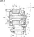
- the torsion damper 20 may be supported on the motor shaft 11.
- the first rotor 21 and the second rotor 22 may be supported on the motor shaft 11.
- the bearing 25 is provided on the motor shaft 11 and the first rotor 21 is rotatably supported on the bearing 25.
- the first rotor 21 is rotatable about the motor shaft 11.
- the second rotor 22 is configured to be not rotatable about the motor shaft 11 but to rotate together with the motor shaft 11.
- the gear 31 is provided on first rotor 21.
- the gear 24 meshing with the gear 31 is supported on the idle shaft 14.
- the idle shaft 14 rotates together with the gear 24. Otherwise, the configuration is similar to that of the embodiment described above (see FIG. 2 ).
- the torsion damper 20 is provided in the power transmission mechanism 15 that transmits the power of the motor shaft 11 to the output shaft 13. As in the embodiment described above, it is possible to improve the operating feel for the rider, and it is possible to reduce the size of the electric power unit 5.
- the torsion damper 20 may be supported on the output shaft 13.
- the number of dampers provided in the power transmission mechanism 15 is not limited to 1.
- a plurality of dampers may be provided in the power transmission mechanism 15.
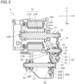
- the embodiment shown in FIG. 5 is an embodiment in which the electric power unit 5 includes the torsion damper 20 supported on the idle shaft 14 and a torsion damper 20B supported on the output shaft 13.
- like elements to those of the embodiment described above will be denoted by like reference signs, and the description thereof will be omitted.
- the torsion damper 20B includes a first rotor 21B and a second rotor 22B supported on the output shaft 13, and a spring 23B interposed between the first rotor 21B and the second rotor 22B.
- the gear 33 meshing with the gear 34 of the idle shaft 14 is provided on the first rotor 21B.
- the first rotor 21B rotates together with the idle shaft 14.
- the first rotor 21B is rotatably supported on a bearing 26 provided on the output shaft 13.
- the first rotor 21B is rotatable about the output shaft 13.
- the second rotor 21B is un-rotatably fixed to the output shaft 13.
- the output shaft 13 rotates together with the second rotor 21B. Otherwise, the configuration is similar to that of the embodiment described above (see FIG. 2 ).
- the torsion damper 20 is provided in the power transmission mechanism 15 that transmits the power of the motor shaft 11 to the output shaft 13. Similar effects to those of the embodiment described above can be obtained.
- another torsion damper 20B is provided in the power transmission mechanism 15. Therefore, it is possible to further enhance the effects described above.
- the sprocket 19 is arranged on one side in the axial direction relative to the middle position 11M of the motor shaft 11 in the axial direction
- the torsion damper 20 is arranged on the other side in the axial direction relative to the middle position 11M of the motor shaft 11 in the axial direction.
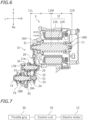
- both of the sprocket 19 and the torsion damper 20 may be arranged on one side in the axial direction relative to the middle position 11M of the motor shaft 11 in the axial direction. For example, as shown in FIG.
- the sprocket 19 and the torsion damper 20 may be arranged leftward relative to the middle position 11M of the motor shaft 11 in the axial direction. Note that in the embodiment shown in FIG. 6 , portions of the power transmission mechanism 15 other than the output shaft 13 are arranged in left-right symmetry with respect to the embodiment shown in FIG. 2 .
- the motorcycle 1 includes a throttle grip 30 (see FIG. 7 ).
- the throttle grip 30 is an example of the throttle operator to be operated by the rider.
- the output of the motor 12 is adjusted by the rider operating the throttle grip 30.
- the control unit 10 is connected to the throttle grip 30 and the motor 12.
- the control unit 10 receives signals from the throttle grip 30 and controls the motor 12 based on the amount of operation of the throttle grip 30.
- the control unit 10 is capable of various controls. The following is an example of the control.
- the control unit 10 can control the motor 12 so that the motor 12 temporarily generates a torque in the reverse direction and then a torque in the forward direction. For example, when the amount of operation per unit time of the throttle grip 30 becomes equal to or greater than a predetermined threshold value while the motor 12 is not rotating, the control unit 10 first causes the motor 12 to temporarily generate a torque in the reverse direction. This causes elastic deformation of the spring 23 of the torsion damper 20, thereby storing energy in the torsion damper 20. Then, the control unit 10 generates a torque in the forward direction on the motor 12.
- the motor 12 starts rotating in the forward direction and the spring 23 restores, thereby releasing the energy stored in the torsion damper 20 (hereinafter referred to as the stored energy). Therefore, the energy of the motor 12 and the stored energy are input to the output shaft 13. An energy that is greater than the energy output by the motor 12 is temporarily input to the output shaft 13. The output shaft 13 can instantaneously output a larger energy. Thus, when the rider suddenly opens the throttle grip 30 wide while the motorcycle 1 is standing, it is possible to rapidly start the motorcycle 1.
- the control unit 10 can control the motor 12 so as to temporarily decrease and then increase the torque of the motor 12. For example, when the amount of operation per unit time of the throttle grip 30 becomes equal to or greater than a predetermined threshold value while the motor 12 is rotating, the control unit 10 first temporarily decreases the torque of the motor 12. For example, the torque of motor 12 is decreased from the first torque to the second torque. This causes elastic deformation of the spring 23 of the torsion damper 20, thereby storing energy in the torsion damper 20. Then, the control unit 10 increases the torque of the motor 12. For example, the torque of the motor 12 is increased from the second torque to the third torque that is greater than the first torque.
- the torque of the motor 12 increases and the spring 23 restores, thereby releasing the energy stored in the torsion damper 20.
- the output shaft 13 can instantaneously output a larger energy.
- the control unit 10 can control the motor 12 so that the torque of the motor 12 varies periodically. Since the torsion damper 20 includes the spring 23, the torsion damper 20 has a natural period. If the fluctuation period of the torque of the motor 12 is made to be equal to or closer to the natural period of the torsion damper 20, it is possible to produce resonance. By using this resonance, it is possible to output a larger energy from the output shaft 13. For example, when the motorcycle 1 runs at a constant speed, the rider keeps constant the amount of operation of the throttle grip 30. Then, the control unit 10 receives a steady drive signal from the throttle grip 30. The control unit 10 controls the motor 12 so that the torque of the motor 12 changes periodically while a steady drive signal is received.
- control unit 10 controls the motor 12 so that the fluctuation period of the torque of the motor 12 is a predetermined set period based on the natural period of the torsion damper 20. Then, it is possible to produce resonance. By using the resonance, it is possible to output a larger driving force from the output shaft 13. A larger driving force can be output from the output shaft 13 without increasing the torque of the motor 12.
- the motor shaft 11, the output shaft 13 and the idle shaft 14 are parallel to each other in the embodiments described above, at least one of them may be nonparallel to at least one other.
- the idle shaft 14 may be optional.
- a straddled vehicle refers to a vehicle that is straddled by the rider.
- a straddled vehicle is not limited to an off-road motorcycle.
- a straddled vehicle is not limited to the motorcycle 1.
- a straddled vehicle may be, for example, an auto tricycle, an ATV (All Terrain Vehicle), or a snowmobile.
- the present invention includes any and all preferred embodiments including equivalent elements, modifications, omissions, combinations, adaptations and/or alterations as would be appreciated by those skilled in the art on the basis of the present disclosure.
- the limitations in the claims are to be interpreted broadly based on the language included in the claims and not limited to examples described in the present specification or during the prosecution of the application.
Landscapes
- Engineering & Computer Science (AREA)
- Mechanical Engineering (AREA)
- Chemical & Material Sciences (AREA)
- Combustion & Propulsion (AREA)
- Transportation (AREA)
- General Engineering & Computer Science (AREA)
- Power Engineering (AREA)
- Electric Propulsion And Braking For Vehicles (AREA)
- Motor Power Transmission Devices (AREA)
- Connection Of Motors, Electrical Generators, Mechanical Devices, And The Like (AREA)
Abstract
Description
- The present invention relates to an electric power unit and a straddled vehicle having the same.
- Straddled vehicles have been known in the art that have an electric motor as a driving source for driving. Electric motors are easier to control than internal combustion engines. A clutch and a transmission are necessary for a straddled vehicle having an internal combustion engine, whereas a clutch and a transmission can be omitted for a straddled vehicle having an electric motor (hereinafter referred to as an electric vehicle).
- However, with an electric vehicle without a clutch and a transmission, there is less of so-called play in the power transmission mechanism from the electric motor to the drive wheel. The driving force of the electric motor is transmitted instantaneously to the drive wheel. Therefore, the rider tends to feel a rigid operating feel. Since it is difficult to apply a large instantaneous force to the drive wheel when starting or accelerating, the rider is less likely to feel the power and the tenacity of driving.
-
JP 2019-155986A - With the electric vehicle disclosed in
JP 2019-155986A - The present invention has been made in view of the above, and an object thereof is to provide a relatively small electric power unit and a straddled vehicle having the same, with which it is possible to improve the operating feel for the rider.
- An electric power unit disclosed herein includes an electric motor having a motor shaft, an output shaft for outputting power, a first power transmission mechanism connected to the motor shaft and the output shaft for transmitting power of the motor shaft to the output shaft, and a damper provided in the first power transmission mechanism.
- With the electric power unit described above, since the damper produces play in the first power transmission mechanism, the rider is less likely to feel rigid operating feel. Thus, it is possible to improve the operating feel for the rider. When the rider performs an operation so that the torque of the electric motor increases rapidly when starting or accelerating, part of the energy output by the electric motor is temporarily stored in the damper and then released toward the output shaft. Therefore, even without the energy-storing rotor, it is possible to output a large driving force instantaneously from the output shaft. With the electric power unit described above, there is no need for an energy-storing rotor and a clutch, and it is possible to reduce the size of the electric power unit.
- The damper may be a torsion damper including: a first rotor; a second rotor arranged coaxial with the first rotor; and a spring that is interposed between the first rotor and the second rotor and transmits a torque of the first rotor to the second rotor.
- Thus, since it is possible to relatively reduce the size of the damper, it is possible to reduce the size of the electric power unit.
- The electric power unit may include an idle shaft that is parallel to the motor shaft and/or the output shaft. The first rotor and the second rotor may be supported on the idle shaft.
- Thus, as the torsion damper is supported on the idle shaft, which is separate from the motor shaft and the output shaft, the installation of the torsion damper is unlikely to be constrained by the position of the motor shaft and the output shaft. It is possible to increase the degree of freedom in installation of the torsion damper.
- The first rotor and the second rotor may be supported on the motor shaft. The first rotor and the second rotor may be supported on the output shaft.
- The electric power unit may include a control unit that controls the electric motor so that a torque of the electric motor changes periodically while a steady drive signal is received.
- With the electric power unit described above, a damper is provided in the first power transmission mechanism, and the damper has a natural period. If the control unit performs a control so that the fluctuation period of the torque of the electric motor is made to be equal to or closer to the natural period, it is possible to produce resonance. By using the resonance, it is possible to output a large driving force.
- The control unit may be configured to control the electric motor so that the fluctuation period of the torque of the electric motor is a predetermined set period based on the natural period of the damper.
- Thus, it is possible to make use of resonance, and output a larger driving force from the output shaft.
- The electric power unit may include a control unit that, when starting to drive the electric motor, controls the electric motor so as to temporarily generate a torque in a reverse direction and then generate a torque in a forward direction on the electric motor.
- Then, as the torque in the reverse direction is temporarily generated on the electric motor, energy is stored in the damper. Then, as the torque in the forward direction is generated on the electric motor, the energy stored in the damper is released in addition to the energy output from the electric motor. Thus, it is possible to instantaneously output a large driving force when starting.
- The electric power unit may include a control unit that, when a command to increase a torque of the electric motor is received while the electric motor is running, controls the electric motor so as to temporarily decrease and then increase the torque of the electric motor.
- Then, when the torque of the electric motor is temporarily decreased, energy is stored in the damper. Then, as the torque of the electric motor is increased, the energy stored in the damper is released in addition to the energy output from the electric motor. Therefore, it is possible to instantaneously output a large driving force while running.
- The electric power unit may include another damper provided in the first power transmission mechanism.
- Then, since a plurality of dampers are provided in the first power transmission mechanism, it is possible to further enhance the effects described above.
- A straddled vehicle disclosed herein includes: an electric power unit described above; a drive wheel that is driven by power of the electric motor; and a second power transmission mechanism that connects together the output shaft and the drive wheel.
- The output shaft may include a connecting portion connected to the second power transmission mechanism. The connecting portion may be arranged on one side in an axial direction of the motor shaft relative to a middle position of the motor shaft in the axial direction; and the damper may be arranged on the other side in the axial direction relative to the middle position of the motor shaft in the axial direction.
- The output shaft may include a connecting portion connected to the second power transmission mechanism. The connecting portion and the damper may be arranged on one side in an axial direction of the motor shaft relative to a middle position of the motor shaft in the axial direction.
- The straddled vehicle may be an off-road motorcycle.
- Off-road motorcycles, as compared to on-road motorcycles, tend to be required to instantaneously output a larger driving force from the electric power unit to the drive wheel when starting or accelerating. Therefore, the effects described above are particularly useful.
- According to the present invention, it is possible to provide a relatively small electric power unit and a straddled vehicle having the same, with which it is possible to improve the operating feel for the rider.
-
-
FIG. 1 is a side view of a motorcycle. -
FIG. 2 is a cross-sectional view of an electric power unit according to one embodiment. -
FIG. 3 is a front view of a torsion damper. -
FIG. 4 is a cross-sectional view of an electric power unit according to another embodiment. -
FIG. 5 is a cross-sectional view of an electric power unit according to another embodiment. -
FIG. 6 is a cross-sectional view of an electric power unit according to another embodiment. -
FIG. 7 is a block diagram of a control system for controlling an electric motor. - An embodiment will now be described. As shown in
FIG. 1 , one embodiment of a straddled vehicle to be described below is an off-road motorcycle 1. Herein, the motorcycle 1 is a motocrosser. - The terms front, rear, left, right, up and down, as used in the description below, refer to these directions as viewed from a virtual rider seated on a seat 2 while the motorcycle 1 is standing upright on a horizontal surface with no rider and no load thereon, unless specified otherwise. The designations F, Re, L, R, U and D, as used in the figures, refer to front, rear, left, right, up and down, respectively.
- The motorcycle 1 includes a seat 2, a handle 3, an
electric power unit 5, a front wheel 4, a rear wheel 6, and a chain 7 linking theelectric power unit 5 and the rear wheel 6. The rear wheel 6 is a drive wheel driven by the power of theelectric power unit 5. The motorcycle 1 includes acontrol unit 10 that controls theelectric power unit 5. - The
electric power unit 5 includes an electric motor (hereinafter referred to simply as motor) 12 having amotor shaft 11, and abattery 9.FIG. 2 is a cross-sectional view of theelectric power unit 5. Theelectric power unit 5 includes anoutput shaft 13 that outputs power, apower transmission mechanism 15 that transmits the power of themotor shaft 11 to theoutput shaft 13, and atorsion damper 20 provided in thepower transmission mechanism 15. - The
motor 12 includes arotor 12R fixed to themotor shaft 11 and astator 12S arranged around therotor 12R. In the present embodiment, themotor shaft 11 extends in the left-right direction of the vehicle. Themotor shaft 11 is rotatably supported on abearing 16A and a bearing 16B. - The
power transmission mechanism 15 is an example of the "first power transmission mechanism". In the present embodiment, thepower transmission mechanism 15 is a mechanism that transmits power by a plurality of gears. Note however that thepower transmission mechanism 15 only needs to be a mechanism that transmits the power of themotor shaft 11 to theoutput shaft 13, and there is no particular limitation on its specific configuration. Thepower transmission mechanism 15 is connected to themotor shaft 11 and theoutput shaft 13. Thepower transmission mechanism 15 includes agear 31 fixed to themotor shaft 11, agear 24 meshing with thegear 31, atorsion damper 20 provided with thegear 24, anidle shaft 14 supporting thetorsion damper 20, agear 34 formed on theidle shaft 14, and agear 33 meshing with thegear 34. Thegear 33 is fixed to theoutput shaft 13. Theidle shaft 14 is rotatably supported on abearing 17A and a bearing 17B. Theidle shaft 14 is arranged parallel to themotor shaft 11. Theidle shaft 14 extends in the left-right direction of the vehicle. - The
output shaft 13 is rotatably supported on abearing 18A and a bearing 18B. Theoutput shaft 13 is arranged parallel to themotor shaft 11. Theoutput shaft 13 extends in the left-right direction of the vehicle. Thegear 33 is fixed to the right end of theoutput shaft 13. Asprocket 19 is fixed to the left end of theoutput shaft 13. A chain 7 (seeFIG. 1 ) is wound around thesprocket 19. - The chain 7 is an example of the "second power transmission mechanism" connecting together the
output shaft 13 and the rear wheel 6, which is the drive wheel. Note that thesprocket 19 is an example of the "connecting portion" connected to the second power transmission mechanism of theoutput shaft 13. The chain 7 transmits the power of theoutput shaft 13 to the rear wheel 6. Note however that the second power transmission mechanism is not limited to the chain 7. The second power transmission mechanism may include, for example, a transmission belt or a drive shaft. - Next, the
torsion damper 20 will be described.FIG. 3 is a front view of thetorsion damper 20, as viewed from the left side of the motorcycle 1. Thetorsion damper 20 includes afirst rotor 21, asecond rotor 22 and aspring 23. - The
first rotor 21 and thesecond rotor 22 are supported on theidle shaft 14. Thesecond rotor 22 is arranged coaxial with thefirst rotor 21. Theidle shaft 14 is provided with abearing 25, and thefirst rotor 21 is rotatably supported on thebearing 25. Thefirst rotor 21 is rotatable about theidle shaft 14. Thesecond rotor 22 is not rotatable about theidle shaft 14. Thesecond rotor 22 is configured to rotate together with theidle shaft 14. - The
first rotor 21 has along hole 21a formed therein. Thesecond rotor 22 has apin 22a inserted into thelong hole 21a. Thesecond rotor 22 is rotatable relative to thefirst rotor 21. As thepin 22a contacts the edge of thelong hole 21a, the rotation of thesecond rotor 22 relative to thefirst rotor 21 is regulated. Thesecond rotor 22 is rotatable relative to thefirst rotor 21 until thepin 22a contacts the edge of thelong hole 21a. Thesecond rotor 22 is configured to be rotatable relative to thefirst rotor 21 by a predetermined angle. Note that the number oflong holes 21a andpins 22a is 3 in the present embodiment, but there is no particular limitation thereto. - The
spring 23 is interposed between thefirst rotor 21 and thesecond rotor 22. In other words, thespring 23 is arranged between thefirst rotor 21 and thesecond rotor 22 on the path of power transmission. Thespring 23 transmits the torque of thefirst rotor 21 to thesecond rotor 22. Here, thespring 23 is a coil spring, and the number ofsprings 23 is 3, but there is no particular limitation on the form and the number ofsprings 23. - The
gear 24 is formed on thefirst rotor 21. Here, thegear 24 and thefirst rotor 21 are an integral piece. However, thegear 24 may be formed separately from thefirst rotor 21. - In
FIG. 2 ,reference sign 11L denotes a straight line that indicates the left end position of themotor shaft 11, andreference sign 11R denotes a straight line that indicates the right end position of themotor shaft 11.Reference sign 11M denotes a straight line that indicates the middle position between the left end and the right end of themotor shaft 11. In other words,reference sign 11M denotes the middle position of themotor shaft 11 in the axial direction. In the present embodiment, thesprocket 19 is arranged on one side in the axial direction relative to themiddle position 11M of themotor shaft 11 in the axial direction, and thetorsion damper 20 is arranged on the other side in the axial direction relative to themiddle position 11M of themotor shaft 11 in the axial direction. Here, thesprocket 19 is arranged leftward relative to themiddle position 11M of themotor shaft 11, and thetorsion damper 20 is arranged rightward relative to themiddle position 11M of themotor shaft 11. Note however that thesprocket 19 may be arranged rightward relative to themiddle position 11M of themotor shaft 11, and thetorsion damper 20 may be arranged leftward relative to themiddle position 11M of themotor shaft 11. - The
electric power unit 5 and the motorcycle 1 are configured as described above. Next, the various effects brought about by theelectric power unit 5 and the motorcycle 1 will be described. - With the
electric power unit 5, thetorsion damper 20 is provided in thepower transmission mechanism 15 that transmits the power of themotor shaft 11 to theoutput shaft 13. Since thetorsion damper 20 produces play in thepower transmission mechanism 15, the rider is less likely to feel a rigid operating feel. Thus, it is possible to improve the operating feel for the rider. - When the rider performs an operation so that the torque of the
motor 12 increases rapidly when starting or accelerating, part of the energy output by themotor 12 is temporarily stored in thespring 23 of thetorsion damper 20 and then released toward theoutput shaft 13. With theelectric power unit 5, it is possible to output a large driving force instantaneously from theoutput shaft 13 without separately providing an energy-storing rotor. When the rider performs an operation for rapid start or rapid acceleration, it is possible to make the motorcycle 1 start or accelerate rapidly following the operation. The rider can feel the power and the tenacity of driving of the motorcycle 1 when starting or accelerating. Thus, it is possible to improve the operating feel for the rider. - For example, when the motorcycle 1 runs over a step, the impact generated on the rear wheel 6 may be transmitted to the
electric power unit 5. According to the present embodiment, the impact transmitted to theoutput shaft 13 is absorbed by thetorsion damper 20. Therefore, it is possible to mitigate the impact applied on themotor 12. It is possible to desirably protect themotor 12 from the impact from the road surface. - With the
electric power unit 5, there is no need for an energy-storing rotor and a clutch. Thus, it is possible to reduce the size of theelectric power unit 5. - Note that the damper provided in the
power transmission mechanism 15 is not limited to thetorsion damper 20. Note however that if thetorsion damper 20 is used as the damper of thepower transmission mechanism 15, it is possible to relatively reduce the size of the damper. Thus, it is possible to reduce the size of theelectric power unit 5. - According to the present embodiment, the
torsion damper 20 is supported on theidle shaft 14, which is separate from themotor shaft 11 and theoutput shaft 13. The installation of thetorsion damper 20 is unlikely to be constrained by the position of themotor shaft 11 and theoutput shaft 13. Thus, it is possible to increase the degree of freedom of installation of thetorsion damper 20. - Note however that the
torsion damper 20 may be supported on a shaft other than theidle shaft 14. For example, as shown inFIG. 4 , thetorsion damper 20 may be supported on themotor shaft 11. Thefirst rotor 21 and thesecond rotor 22 may be supported on themotor shaft 11. In the following description, like elements to those of the embodiment described above will be denoted by like reference signs, and the description thereof will be omitted. - In the embodiment shown in
FIG. 4 , thebearing 25 is provided on themotor shaft 11 and thefirst rotor 21 is rotatably supported on thebearing 25. Thefirst rotor 21 is rotatable about themotor shaft 11. Thesecond rotor 22 is configured to be not rotatable about themotor shaft 11 but to rotate together with themotor shaft 11. Thegear 31 is provided onfirst rotor 21. Thegear 24 meshing with thegear 31 is supported on theidle shaft 14. Theidle shaft 14 rotates together with thegear 24. Otherwise, the configuration is similar to that of the embodiment described above (seeFIG. 2 ). - Also in the embodiment shown in
FIG. 4 , thetorsion damper 20 is provided in thepower transmission mechanism 15 that transmits the power of themotor shaft 11 to theoutput shaft 13. As in the embodiment described above, it is possible to improve the operating feel for the rider, and it is possible to reduce the size of theelectric power unit 5. - The
torsion damper 20 may be supported on theoutput shaft 13. The number of dampers provided in thepower transmission mechanism 15 is not limited to 1. A plurality of dampers may be provided in thepower transmission mechanism 15. The embodiment shown inFIG. 5 is an embodiment in which theelectric power unit 5 includes thetorsion damper 20 supported on theidle shaft 14 and a torsion damper 20B supported on theoutput shaft 13. In the following description, like elements to those of the embodiment described above will be denoted by like reference signs, and the description thereof will be omitted. - In the embodiment shown in
FIG. 5 , the torsion damper 20B includes afirst rotor 21B and asecond rotor 22B supported on theoutput shaft 13, and a spring 23B interposed between thefirst rotor 21B and thesecond rotor 22B. Thegear 33 meshing with thegear 34 of theidle shaft 14 is provided on thefirst rotor 21B. Thefirst rotor 21B rotates together with theidle shaft 14. Thefirst rotor 21B is rotatably supported on abearing 26 provided on theoutput shaft 13. Thefirst rotor 21B is rotatable about theoutput shaft 13. Thesecond rotor 21B is un-rotatably fixed to theoutput shaft 13. Theoutput shaft 13 rotates together with thesecond rotor 21B. Otherwise, the configuration is similar to that of the embodiment described above (seeFIG. 2 ). - Also in the embodiment shown in
FIG. 5 , thetorsion damper 20 is provided in thepower transmission mechanism 15 that transmits the power of themotor shaft 11 to theoutput shaft 13. Similar effects to those of the embodiment described above can be obtained. In addition, according to the embodiment shown inFIG. 5 , another torsion damper 20B is provided in thepower transmission mechanism 15. Therefore, it is possible to further enhance the effects described above. - In the embodiment shown in
FIG. 2 , thesprocket 19 is arranged on one side in the axial direction relative to themiddle position 11M of themotor shaft 11 in the axial direction, and thetorsion damper 20 is arranged on the other side in the axial direction relative to themiddle position 11M of themotor shaft 11 in the axial direction. However, there is no particular limitation on the arrangement of thesprocket 19 and thetorsion damper 20. Both of thesprocket 19 and thetorsion damper 20 may be arranged on one side in the axial direction relative to themiddle position 11M of themotor shaft 11 in the axial direction. For example, as shown inFIG. 6 , thesprocket 19 and thetorsion damper 20 may be arranged leftward relative to themiddle position 11M of themotor shaft 11 in the axial direction. Note that in the embodiment shown inFIG. 6 , portions of thepower transmission mechanism 15 other than theoutput shaft 13 are arranged in left-right symmetry with respect to the embodiment shown inFIG. 2 . - Although not shown in
FIG. 1 , the motorcycle 1 includes a throttle grip 30 (seeFIG. 7 ). Thethrottle grip 30 is an example of the throttle operator to be operated by the rider. The output of themotor 12 is adjusted by the rider operating thethrottle grip 30. Thecontrol unit 10 is connected to thethrottle grip 30 and themotor 12. Thecontrol unit 10 receives signals from thethrottle grip 30 and controls themotor 12 based on the amount of operation of thethrottle grip 30. Thecontrol unit 10 is capable of various controls. The following is an example of the control. - When starting to drive the
motor 12, thecontrol unit 10 can control themotor 12 so that themotor 12 temporarily generates a torque in the reverse direction and then a torque in the forward direction. For example, when the amount of operation per unit time of thethrottle grip 30 becomes equal to or greater than a predetermined threshold value while themotor 12 is not rotating, thecontrol unit 10 first causes themotor 12 to temporarily generate a torque in the reverse direction. This causes elastic deformation of thespring 23 of thetorsion damper 20, thereby storing energy in thetorsion damper 20. Then, thecontrol unit 10 generates a torque in the forward direction on themotor 12. Thus, themotor 12 starts rotating in the forward direction and thespring 23 restores, thereby releasing the energy stored in the torsion damper 20 (hereinafter referred to as the stored energy). Therefore, the energy of themotor 12 and the stored energy are input to theoutput shaft 13. An energy that is greater than the energy output by themotor 12 is temporarily input to theoutput shaft 13. Theoutput shaft 13 can instantaneously output a larger energy. Thus, when the rider suddenly opens thethrottle grip 30 wide while the motorcycle 1 is standing, it is possible to rapidly start the motorcycle 1. - When a command to increase the torque of the
motor 12 is received while themotor 12 is running, thecontrol unit 10 can control themotor 12 so as to temporarily decrease and then increase the torque of themotor 12. For example, when the amount of operation per unit time of thethrottle grip 30 becomes equal to or greater than a predetermined threshold value while themotor 12 is rotating, thecontrol unit 10 first temporarily decreases the torque of themotor 12. For example, the torque ofmotor 12 is decreased from the first torque to the second torque. This causes elastic deformation of thespring 23 of thetorsion damper 20, thereby storing energy in thetorsion damper 20. Then, thecontrol unit 10 increases the torque of themotor 12. For example, the torque of themotor 12 is increased from the second torque to the third torque that is greater than the first torque. Then, the torque of themotor 12 increases and thespring 23 restores, thereby releasing the energy stored in thetorsion damper 20. Theoutput shaft 13 can instantaneously output a larger energy. Thus, if the rider suddenly opens thethrottle grip 30 wide while the motorcycle 1 is running, the motorcycle 1 can accelerate rapidly. - The
control unit 10 can control themotor 12 so that the torque of themotor 12 varies periodically. Since thetorsion damper 20 includes thespring 23, thetorsion damper 20 has a natural period. If the fluctuation period of the torque of themotor 12 is made to be equal to or closer to the natural period of thetorsion damper 20, it is possible to produce resonance. By using this resonance, it is possible to output a larger energy from theoutput shaft 13. For example, when the motorcycle 1 runs at a constant speed, the rider keeps constant the amount of operation of thethrottle grip 30. Then, thecontrol unit 10 receives a steady drive signal from thethrottle grip 30. Thecontrol unit 10 controls themotor 12 so that the torque of themotor 12 changes periodically while a steady drive signal is received. For example, thecontrol unit 10 controls themotor 12 so that the fluctuation period of the torque of themotor 12 is a predetermined set period based on the natural period of thetorsion damper 20. Then, it is possible to produce resonance. By using the resonance, it is possible to output a larger driving force from theoutput shaft 13. A larger driving force can be output from theoutput shaft 13 without increasing the torque of themotor 12. - Some embodiments have been described above, but the aforementioned embodiments are merely illustrative. Various other embodiments are possible.
- While the
motor shaft 11, theoutput shaft 13 and theidle shaft 14 are parallel to each other in the embodiments described above, at least one of them may be nonparallel to at least one other. Where thetorsion damper 20 is supported on themotor shaft 11 or theoutput shaft 13, theidle shaft 14 may be optional. - A straddled vehicle refers to a vehicle that is straddled by the rider. A straddled vehicle is not limited to an off-road motorcycle. A straddled vehicle is not limited to the motorcycle 1. A straddled vehicle may be, for example, an auto tricycle, an ATV (All Terrain Vehicle), or a snowmobile.
- The terms and expressions used herein are used for explanation purposes and should not be construed as being restrictive. It should be appreciated that the terms and expressions used herein do not eliminate any equivalents of features illustrated and mentioned herein, but include various modifications falling within the claimed scope of the present invention. The present invention may be embodied in many different forms. The present disclosure is to be considered as providing examples of the principles of the invention. These examples are described herein with the understanding that such examples are not intended to limit the present invention to preferred embodiments described herein and/or illustrated herein. Hence, the present invention is not limited to the preferred embodiments described herein. The present invention includes any and all preferred embodiments including equivalent elements, modifications, omissions, combinations, adaptations and/or alterations as would be appreciated by those skilled in the art on the basis of the present disclosure. The limitations in the claims are to be interpreted broadly based on the language included in the claims and not limited to examples described in the present specification or during the prosecution of the application.
- 1: Motorcycle (straddled vehicle), 5: Electric power unit, 6: Rear wheel (drive wheel), 7: Chain (second power transmission mechanism), 10: Control unit, 11: Motor shaft, 12: Electric motor, 13: Output shaft, 14: Idle shaft, 15: Power transmission mechanism (first power transmission mechanism), 19: Sprocket (connecting portion), 20: Torsion damper (damper), 20B: Torsion damper (the other damper), 21: First rotor, 22: Second rotor, 23: Spring
Claims (14)
- An electric power unit (5), comprising:an electric motor (12) having a motor shaft (11);an output shaft (13) that outputs power;a first power transmission mechanism (15) that is connected to the motor shaft (11) and the output shaft (13) and transmits power of the motor shaft (11) to the output shaft (13); anda damper (20) provided in the first power transmission mechanism (15).
- The electric power unit (5) according to claim 1, wherein:
the damper is a torsion damper (20) including:a first rotor (21);a second rotor (22) arranged coaxial with the first rotor (21); anda spring (23) that is interposed between the first rotor (21) and the second rotor (22) and transmits a torque of the first rotor (21) to the second rotor (22). - The electric power unit (5) according to claim 2, comprising:an idle shaft (14) that is parallel to the motor shaft (11) and/or the output shaft (13),wherein the first rotor (21) and the second rotor (22) are supported on the idle shaft (14).
- The electric power unit (5) according to claim 2, wherein the first rotor (21) and the second rotor (22) are supported on the motor shaft (11).
- The electric power unit (5) according to claim 2, wherein the first rotor (21) and the second rotor (22) are supported on the output shaft (13).
- The electric power unit (5) according to any one of claims 1 to 5, comprising a control unit (10) that controls the electric motor (12) so that a torque of the electric motor (12) changes periodically while a steady drive signal is received.
- The electric power unit (5) according to claim 6, wherein the control unit (10) is configured to control the electric motor (12) so that a fluctuation period of the torque of the electric motor (12) is a predetermined set period based on a natural period of the damper (20).
- The electric power unit (5) according to any one of claims 1 to 5, comprising a control unit (10) that, when starting to drive the electric motor (12), controls the electric motor (12) so as to temporarily generate a torque in a reverse direction and then generate a torque in a forward direction on the electric motor (12).
- The electric power unit (5) according to any one of claims 1 to 5, comprising a control unit (10) that, when a command to increase a torque of the electric motor (12) is received while the electric motor (12) is running, controls the electric motor (12) so as to temporarily decrease and then increase the torque of the electric motor (12).
- The electric power unit (5) according to any one of claims 1 to 9, comprising another damper (20B) provided in the first power transmission mechanism (15).
- A straddled vehicle (1), comprising:an electric power unit (5) according to any one of claims 1 to 10;a drive wheel (6) that is driven by power of the electric motor (12); anda second power transmission mechanism (7) that connects together the output shaft (13) and the drive wheel (6).
- The straddled vehicle (1) according to claim 11, wherein:the output shaft (13) includes a connecting portion (19) connected to the second power transmission mechanism (7);the connecting portion (19) is arranged on one side in an axial direction of the motor shaft (11) relative to a middle position (11M) of the motor shaft (11) in the axial direction; andthe damper (20) is arranged on the other side in the axial direction relative to the middle position (11M) of the motor shaft (11) in the axial direction.
- The straddled vehicle (1) according to claim 11, wherein:the output shaft (13) includes a connecting portion (19) connected to the second power transmission mechanism (7); andthe connecting portion (19) and the damper (20) are arranged on one side in an axial direction of the motor shaft (11) relative to a middle position (11M) of the motor shaft (11) in the axial direction.
- The straddled vehicle (1) according to any one of claims 11 to 13, wherein the straddled vehicle (1) is an off-road motorcycle.
Applications Claiming Priority (1)
| Application Number | Priority Date | Filing Date | Title |
|---|---|---|---|
| JP2022132180A JP2024029797A (en) | 2022-08-23 | 2022-08-23 | Electric power unit and straddle-type vehicle equipped with it |
Publications (1)
| Publication Number | Publication Date |
|---|---|
| EP4329159A1 true EP4329159A1 (en) | 2024-02-28 |
Family
ID=85601567
Family Applications (1)
| Application Number | Title | Priority Date | Filing Date |
|---|---|---|---|
| EP23161421.5A Withdrawn EP4329159A1 (en) | 2022-08-23 | 2023-03-13 | Electric power unit and straddled vehicle having the same |
Country Status (3)
| Country | Link |
|---|---|
| US (1) | US20240067302A1 (en) |
| EP (1) | EP4329159A1 (en) |
| JP (1) | JP2024029797A (en) |
Families Citing this family (1)
| Publication number | Priority date | Publication date | Assignee | Title |
|---|---|---|---|---|
| USD1024852S1 (en) * | 2024-01-19 | 2024-04-30 | Shenzhen Jianyue Intelligent Technology Co., Ltd. | Children's off-road electric motorcycle |
Citations (9)
| Publication number | Priority date | Publication date | Assignee | Title |
|---|---|---|---|---|
| JP4377561B2 (en) * | 2001-12-20 | 2009-12-02 | 本田技研工業株式会社 | Electric vehicle power unit structure |
| CN100574056C (en) * | 2005-08-05 | 2009-12-23 | 雅马哈发动机株式会社 | The method of the Straddle-type vehicle and the mounting rotary electric machine of electric rotating machine is housed |
| US20130244800A1 (en) * | 2010-11-19 | 2013-09-19 | Toyota Jidosha Kabushiki Kaisha | Vehicular damper device |
| CN203896173U (en) * | 2014-03-03 | 2014-10-22 | 张雅玲 | Power generation device with reduced footprint |
| JP3194344U (en) * | 2014-09-05 | 2014-11-13 | 雅玲 張 | Power generation device that can reduce the occupied area |
| CN206211731U (en) * | 2016-11-09 | 2017-05-31 | 浙江吉利新能源商用车有限公司 | Distance increasing unit electric generator structure |
| JP2019155986A (en) | 2018-03-08 | 2019-09-19 | ヤマハ発動機株式会社 | Electric power unit and electric vehicle |
| JP6658013B2 (en) * | 2016-02-01 | 2020-03-04 | 日本精工株式会社 | Rotation fluctuation reduction device |
| GB2596146A (en) * | 2020-06-19 | 2021-12-22 | Andalus Tech Ltd | Apparatus and method |
Family Cites Families (5)
| Publication number | Priority date | Publication date | Assignee | Title |
|---|---|---|---|---|
| DE102004052023A1 (en) * | 2004-10-26 | 2006-04-27 | Deere & Company, Moline | Device for generating electrical energy for an agricultural or industrial utility vehicle |
| DE102010009832A1 (en) * | 2010-03-02 | 2011-09-08 | Ivd Prof. Hohenberg Gmbh | Motor vehicle with combined drive |
| JP5545413B2 (en) * | 2011-07-19 | 2014-07-09 | トヨタ自動車株式会社 | Lubricating device for hybrid vehicle power transmission device |
| US10220830B2 (en) * | 2016-12-14 | 2019-03-05 | Bendix Commercial Vehicle Systems | Front end motor-generator system and hybrid electric vehicle operating method |
| JP7198103B2 (en) * | 2019-02-05 | 2022-12-28 | 株式会社エクセディ | damper device |
-
2022
- 2022-08-23 JP JP2022132180A patent/JP2024029797A/en active Pending
-
2023
- 2023-03-13 EP EP23161421.5A patent/EP4329159A1/en not_active Withdrawn
- 2023-07-17 US US18/353,189 patent/US20240067302A1/en active Pending
Patent Citations (9)
| Publication number | Priority date | Publication date | Assignee | Title |
|---|---|---|---|---|
| JP4377561B2 (en) * | 2001-12-20 | 2009-12-02 | 本田技研工業株式会社 | Electric vehicle power unit structure |
| CN100574056C (en) * | 2005-08-05 | 2009-12-23 | 雅马哈发动机株式会社 | The method of the Straddle-type vehicle and the mounting rotary electric machine of electric rotating machine is housed |
| US20130244800A1 (en) * | 2010-11-19 | 2013-09-19 | Toyota Jidosha Kabushiki Kaisha | Vehicular damper device |
| CN203896173U (en) * | 2014-03-03 | 2014-10-22 | 张雅玲 | Power generation device with reduced footprint |
| JP3194344U (en) * | 2014-09-05 | 2014-11-13 | 雅玲 張 | Power generation device that can reduce the occupied area |
| JP6658013B2 (en) * | 2016-02-01 | 2020-03-04 | 日本精工株式会社 | Rotation fluctuation reduction device |
| CN206211731U (en) * | 2016-11-09 | 2017-05-31 | 浙江吉利新能源商用车有限公司 | Distance increasing unit electric generator structure |
| JP2019155986A (en) | 2018-03-08 | 2019-09-19 | ヤマハ発動機株式会社 | Electric power unit and electric vehicle |
| GB2596146A (en) * | 2020-06-19 | 2021-12-22 | Andalus Tech Ltd | Apparatus and method |
Also Published As
| Publication number | Publication date |
|---|---|
| JP2024029797A (en) | 2024-03-07 |
| US20240067302A1 (en) | 2024-02-29 |
Similar Documents
| Publication | Publication Date | Title |
|---|---|---|
| EP2108865B1 (en) | Power unit and straddle-type vehicle provided with the power unit | |
| EP1953426A2 (en) | Continuously variable transmission | |
| JPWO2006001410A1 (en) | Belt type continuously variable transmission for saddle riding type vehicle and saddle riding type vehicle | |
| EP1953428B1 (en) | Transmission | |
| EP2093120A1 (en) | Drive source control device for vehicle | |
| EP3879086B1 (en) | Electric supercharger-equipped moving machine | |
| WO2011125222A1 (en) | Vehicle driving force control device | |
| US20240067302A1 (en) | Electric power unit and straddled vehicle having the same | |
| JP2006046324A (en) | Power unit | |
| US10808769B2 (en) | Clutch device and straddle-type vehicle and vehicle provided with same | |
| WO2006109375A1 (en) | Hybrid drive device for vehicle | |
| JP3291983B2 (en) | Vehicle drive system | |
| JP3855905B2 (en) | Hybrid vehicle drive system | |
| JP2002104000A (en) | Hybrid drive | |
| JP6007999B2 (en) | Four-wheel drive vehicle control device and four-wheel drive vehicle | |
| JP7485848B2 (en) | Straddled Vehicle | |
| JP2006232162A (en) | Hybrid vehicle | |
| EP4139566B1 (en) | Belt integrated starter generator torque control | |
| EP3967903B1 (en) | Straddled vehicle | |
| US11872883B2 (en) | Powertrain for a motor vehicle and control method thereof | |
| US20210387697A1 (en) | Motorcycle | |
| US10807460B2 (en) | Method of controlling a powertrain system of a vehicle | |
| US11085533B2 (en) | Vehicle power unit | |
| KR102406122B1 (en) | Device for torque vectoring | |
| JP6788937B2 (en) | Power transmission device |
Legal Events
| Date | Code | Title | Description |
|---|---|---|---|
| PUAI | Public reference made under article 153(3) epc to a published international application that has entered the european phase |
Free format text: ORIGINAL CODE: 0009012 |
|
| STAA | Information on the status of an ep patent application or granted ep patent |
Free format text: STATUS: THE APPLICATION HAS BEEN PUBLISHED |
|
| AK | Designated contracting states |
Kind code of ref document: A1 Designated state(s): AL AT BE BG CH CY CZ DE DK EE ES FI FR GB GR HR HU IE IS IT LI LT LU LV MC ME MK MT NL NO PL PT RO RS SE SI SK SM TR |
|
| P01 | Opt-out of the competence of the unified patent court (upc) registered |
Effective date: 20240307 |
|
| STAA | Information on the status of an ep patent application or granted ep patent |
Free format text: STATUS: REQUEST FOR EXAMINATION WAS MADE |
|
| 17P | Request for examination filed |
Effective date: 20240524 |
|
| RBV | Designated contracting states (corrected) |
Designated state(s): AL AT BE BG CH CY CZ DE DK EE ES FI FR GB GR HR HU IE IS IT LI LT LU LV MC ME MK MT NL NO PL PT RO RS SE SI SK SM TR |
|
| STAA | Information on the status of an ep patent application or granted ep patent |
Free format text: STATUS: EXAMINATION IS IN PROGRESS |
|
| 17Q | First examination report despatched |
Effective date: 20241002 |
|
| STAA | Information on the status of an ep patent application or granted ep patent |
Free format text: STATUS: THE APPLICATION IS DEEMED TO BE WITHDRAWN |
|
| 18D | Application deemed to be withdrawn |
Effective date: 20250204 |