EP4328813A1 - Detection device, detection method, and detection program - Google Patents
Detection device, detection method, and detection program Download PDFInfo
- Publication number
- EP4328813A1 EP4328813A1 EP21943111.1A EP21943111A EP4328813A1 EP 4328813 A1 EP4328813 A1 EP 4328813A1 EP 21943111 A EP21943111 A EP 21943111A EP 4328813 A1 EP4328813 A1 EP 4328813A1
- Authority
- EP
- European Patent Office
- Prior art keywords
- data
- lpips
- distance
- detection device
- detection
- Prior art date
- Legal status (The legal status is an assumption and is not a legal conclusion. Google has not performed a legal analysis and makes no representation as to the accuracy of the status listed.)
- Pending
Links
Images



Classifications
-
- G—PHYSICS
- G06—COMPUTING OR CALCULATING; COUNTING
- G06N—COMPUTING ARRANGEMENTS BASED ON SPECIFIC COMPUTATIONAL MODELS
- G06N3/00—Computing arrangements based on biological models
- G06N3/02—Neural networks
- G06N3/08—Learning methods
-
- G—PHYSICS
- G06—COMPUTING OR CALCULATING; COUNTING
- G06V—IMAGE OR VIDEO RECOGNITION OR UNDERSTANDING
- G06V10/00—Arrangements for image or video recognition or understanding
- G06V10/70—Arrangements for image or video recognition or understanding using pattern recognition or machine learning
- G06V10/764—Arrangements for image or video recognition or understanding using pattern recognition or machine learning using classification, e.g. of video objects
-
- G—PHYSICS
- G06—COMPUTING OR CALCULATING; COUNTING
- G06F—ELECTRIC DIGITAL DATA PROCESSING
- G06F18/00—Pattern recognition
- G06F18/20—Analysing
- G06F18/24—Classification techniques
- G06F18/241—Classification techniques relating to the classification model, e.g. parametric or non-parametric approaches
- G06F18/2413—Classification techniques relating to the classification model, e.g. parametric or non-parametric approaches based on distances to training or reference patterns
- G06F18/24133—Distances to prototypes
-
- G—PHYSICS
- G06—COMPUTING OR CALCULATING; COUNTING
- G06V—IMAGE OR VIDEO RECOGNITION OR UNDERSTANDING
- G06V10/00—Arrangements for image or video recognition or understanding
- G06V10/70—Arrangements for image or video recognition or understanding using pattern recognition or machine learning
- G06V10/74—Image or video pattern matching; Proximity measures in feature spaces
- G06V10/761—Proximity, similarity or dissimilarity measures
-
- G—PHYSICS
- G06—COMPUTING OR CALCULATING; COUNTING
- G06V—IMAGE OR VIDEO RECOGNITION OR UNDERSTANDING
- G06V20/00—Scenes; Scene-specific elements
- G06V20/50—Context or environment of the image
- G06V20/56—Context or environment of the image exterior to a vehicle by using sensors mounted on the vehicle
- G06V20/58—Recognition of moving objects or obstacles, e.g. vehicles or pedestrians; Recognition of traffic objects, e.g. traffic signs, traffic lights or roads
- G06V20/582—Recognition of moving objects or obstacles, e.g. vehicles or pedestrians; Recognition of traffic objects, e.g. traffic signs, traffic lights or roads of traffic signs
Definitions
- the present invention relates to a detection device, a detection method, and a detection program.
- Adversarial Example which is an adverse sample created by artificially adding a minute noise to data, which is to be input to a deep learning model, so as to disturb an output (see NPL 1).
- an Adversarial Example of an image has the problem of misclassifying the output of deep learning without changing its appearance and without human recognition.
- the type of a sign recognized by an automated vehicle is changed to another type. Accordingly, since the Adversarial Example poses a major threat for the safety of AI services, the creation of countermeasure techniques for it in deep learning is expected.
- Measures against the Adversarial Example are classified into several groups according to its policy. For example, there are four typical policies as follows: (1) a robust deep learning model capable of normally classifying an Adversarial Example is learned; (2) an Adversarial Example is detected and removed before being input to the deep learning model; (3) delete perturbation added to the Adversarial Example, to restore the original data; (4) disturb the use of model information necessary for creating the Adversarial Example.
- the present invention has been made in view of the above, and an object of the present invention is to detect and remove an Adversarial Example before inputting it into a deep learning model.
- a detection device includes: an acquisition unit configured to acquire data to be detected and normal reference data; a calculation unit configured to calculate a Learned Perceptual Image Patch Similarity (LPIPS) distance between the acquired data and the reference data; and a classification unit configured to classify the acquired data into either a Clean Sample or an Adversarial Example by using the calculated LPIPS distance.
- LPIPS Learned Perceptual Image Patch Similarity
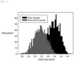
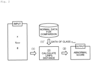
- Figs. 1 and 2 are diagrams for explaining an outline of a detection device according to the present embodiment.
- the detection device of the present embodiment detects an Adversarial Example by using an LPIPS (Learned Perceptual Image Patch Similarity) distance which is the latest index for measuring the distance between images.
- LPIPS Learning Perceptual Image Patch Similarity
- the LPIPS distance is an index for measuring the distance between images by normalizing an intermediate output of a deep learning model for each channel and obtaining a difference, the index being a value calculated as shown by the following equation (1).
- the detection device classifies the Adversarial Example and the Clean Sample according to the difference in LPIPS distance, thereby detecting the Adversarial Example.
- the detection device accepts inputs of data x to be detected, its prediction class y_pred, a deep learning model g, and data belonging to class y_pred out of the reference data which is normal data for comparison (shown in (1), (1)' in Fig. 2 ).
- the detection device also calculates the LPIPS distance between the data x and the reference data belonging to class y_pred ((2) shown in Fig. 2 ), and outputs the minimum value out of these values as an abnormality score ((3) shown in Fig. 2 ). Then, the detection device classifies the data x into normal/abnormal states, that is, into Clean Sample/Adversarial Example, by using the abnormality score.
- the detection device detects and removes the Adversarial Example before inputting it to the deep learning model g, allowing for countermeasures against the Adversarial Example without modifying the deep learning model g.
- Fig. 3 is a schematic diagram illustrating a schematic configuration of the detection device according to the present embodiment.
- a detection device 10 according to the present embodiment is implemented by a general computer such as a personal computer, and includes an input unit 11, an output unit 12, a communication control unit 13, a storage unit 14, and a control unit 15.
- the input unit 11 is realized by using an input device such as a keyboard or a mouse, and inputs various pieces of instruction information, such as start of processing, to the control unit 15 in response to an input operation from an operator.
- the output unit 12 is realized by a display device such as a liquid crystal display, a printing device such as a printer, or the like. For example, a result of detection processing to be described below is displayed on the output unit 12.
- the communication control unit 13 is implemented by, for example, a Network Interface Card (NIC), and controls electric communication between the control unit 15 and an external device via a telecommunication line such as a Local Area Network (LAN) or the Internet.
- NIC Network Interface Card
- LAN Local Area Network
- the communication control unit 13 controls communication between the control unit 15 and a management device or the like that manages data to be subjected to detection processing.
- the storage unit 14 is realized by a semiconductor memory element such as a RAM (Random Access Memory) or a flash memory, or a storage device such as a hard disk or an optical disc.
- the storage unit 14 stores in advance, for example, a processing program that operates the detection device 10 and data to be used during execution of the processing program, or the storage unit 14 stores the processing program and the data temporarily every time the processing is executed.
- the storage unit 14 stores a model 14a used for detection processing to be described below. Note that the storage unit 14 may also be configured to communicate with the control unit 15 via the communication control unit 13.
- control unit 15 is implemented by using a CPU (Central Processing Unit) or the like, and executes a processing program stored in a memory.
- the control unit 15 functions as an acquisition unit 15a, a calculation unit 15b, a learning unit 15c, and a classification unit 15d, as illustrated in Fig. 2 .
- each or some of these functional units may be mounted on a different piece of hardware.
- the learning unit 15c may be mounted on hardware different from other functional units.
- control unit 15 may include another functional unit.
- the acquisition unit 15a acquires data to be detected and normal reference data.
- the acquisition unit 15a acquires data to be subjected to detection processing described later and the reference data which is the normal data for comparison, from the management device or the like via the input unit 11 or the communication control unit 13.
- the acquisition unit 15a may store the acquired data and the reference data into the storage unit 14.
- the calculation unit 15b described later acquires the data and the reference data from the storage unit 14 and executes processing.
- the calculation unit 15b calculates an LPIPS distance between the acquired data and the reference data. Specifically, the calculation unit 15b calculates the LPIPS distance between the data x to be detected and the reference data which is the normal data for comparison, according to the equation (1), as described above. The calculation unit 15b delivers the minimum value among LPIPS distances calculated between each pieces of data and a plurality of pieces of reference data, as an abnormality score of the data, to the learning unit 15c and the classification unit 15d described later.
- the learning unit 15c learns the model 14a for classifying data into normal or abnormal by using the calculated LPIPS distance as an abnormality score. Specifically, the learning unit 15c generates the model 14a for classifying each piece of data by learning, so that the abnormality score of each piece of data calculated by the calculation unit 15b, that is, the LPIPS distance, follows the distribution illustrated in Fig. 1 .
- the generated model 14a outputs whether the input data are normal data, that is, Clean Sample, or abnormal data, that is, Adversarial Example.
- the classification unit 15d classifies the acquired data into either a Clean Sample or an Adversarial Example by using the calculated LPIPS distance. Specifically, the classification unit 15d classifies the acquired data into either normal Clean Sample or abnormal Adversarial Example by using the model 14a for classifying the data into either normal or abnormal, with the calculated LPIPS distance as an abnormality score. That is, the classification unit 15d classifies the acquired data to be detected, into either normal data, that is, Clean Sample, or abnormal data, that is, Adversarial Example, by using the learned model 14a.
- the classification unit 15d outputs the Adversarial Example to the output unit 12.
- the detection device 10 can detect an Adversarial Example accurately. Therefore, the Adversarial Example is removed before being input to the deep learning model g, and countermeasures against the Adversarial Example can be taken without modifying the deep learning model g.
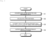
- Fig. 4 is a flow chart illustrating a detection processing procedure.
- the flow chart shown in Fig. 4 starts at the timing when the user makes an operation input indicating the start.
- the acquisition unit 15a acquires data to be detected and reference data (step S1). For example, the acquisition unit 15a acquires data to be subjected to the detection processing and reference data which is the normal data for comparison, via the input unit 11 or the communication control unit 13.
- the calculation unit 15b calculates an LPIPS distance between the acquired data to be detected and the reference data (step S2).
- the calculation unit 15b delivers the minimum value out of the LPIPS distances calculated between each piece of data and a plurality of pieces of reference data, to the classification unit 15d, as an abnormality score of the data.
- the calculation unit 15b may deliver the calculated abnormality score to the learning unit 15c.
- the learning unit 15c learns the model 14a for classifying the data into normal or abnormal, and stores the generated model 14a in the storage unit 14.
- the classification unit 15d classifies the acquired data into either a Clean Sample or an Adversarial Example by using the calculated LPIPS distance (step S3). Specifically, the classification unit 15d classifies the acquired data to be detected, into either normal data, that is, Clean Sample, or abnormal data, that is, Adversarial Example, by using the learned model 14a.
- the classification unit 15d outputs the Adversarial Example to another device or the like as a detection result via the output unit 12 and the communication control unit 13 (step S4). In this manner, a series of detection processing are finished.
- the acquisition unit 15a acquires the data to be detected and the normal reference data.
- the calculation unit 15b calculates an LPIPS distance between the acquired data and the reference data.
- the classification unit 15d also classifies the acquired data into either a Clean Sample or an Adversarial Example by using the calculated LPIPS distance.
- the classification unit 15d classifies the acquired data into either a normal Clean Sample or an abnormal Adversarial Example by using the model 14a for classifying the data into either normal or abnormal, with the calculated LPIPS distance as an abnormality score.
- the detection device 10 can detect an Adversarial Example accurately. Therefore, the Adversarial Example is removed before being input to the deep learning model, and countermeasures against the Adversarial Example, which is a major threat to the safety of AI services, can be taken without modifying the deep learning model. Thus, the detection device 10 can secure the safety of AI services.
- the learning unit 15c learns the model 14a for classifying the data into normal or abnormal by using the calculated LPIPS distance as an abnormality score. Therefore, the detection device 10 can accurately detect an Adversarial Example that continues to change day by day.
- Figs. 5 and 6 are diagrams for explaining an example.
- Fig. 5 is a ROC (Receiver Operating Characteristic Curve) curve showing the result of the detection process of the above-described embodiment with respect to the Adversarial Example and Clean Sample shown in the histogram of Fig. 1 .
- ResNet 18 is applied for the deep learning model
- cifar10 is applied for the data set
- PGD see "https://arxiv.org/abs/1706.06083" is applied for the Adversarial Example.
- an AUC (Area Under Curve) value of the ROC curve which indicates that the closer to 1 the model is, the higher the performance, is 0.88, confirming that Adversarial Example can be detected with high accuracy.
- Fig. 6 illustrates an example of applying the detection device 10 according to the foregoing embodiment to a sign classification system.
- the acquisition unit 15a acquires a sign photographed by a camera as data to be detected, and the classification unit 15d detects an Adversarial Example. Then, the detection device 10 discards an Adversarial Example when the Adversarial Example is detected, and inputs the Adversarial Example to the deep learning model when the Adversarial Example is not detected.
- the detection device 10 discards an Adversarial Example when the Adversarial Example is detected, and inputs the Adversarial Example to the deep learning model when the Adversarial Example is not detected.
- erroneous recognition of a sign by an automated vehicle is prevented, and safety of vehicle body control can be secured.
- the detection device 10 can be implemented by installing a detection program for executing the detection processing as package software or online software in a desired computer.
- the information processing device can be caused to function as the detection device 10.
- the information processing device described herein can be a desktop type or laptop type personal computer.
- the information processing device can be a mobile communication terminal such as a smartphone, a mobile phone, and a PHS (Personal Handyphone System), and a slate terminal such as a PDA (Personal Digital Assistant).
- the function of the detection device 10 may be implemented by a cloud server.
- FIG. 7 is a diagram illustrating an example of a computer that executes the detection program.
- a computer 1000 has a memory 1010, a CPU 1020, a hard disk drive interface 1030, a disk drive interface 1040, a serial port interface 1050, a video adapter 1060, and a network interface 1070, for example. These units are connected by a bus 1080.
- the memory 1010 includes a ROM (Read Only Memory) 1011 and a RAM 1012.
- the ROM 1011 stores, for example, a boot program such as a BIOS (Basic Input Output System).
- BIOS Basic Input Output System
- the hard disk drive interface 1030 is connected to a hard disk drive 1031.
- the disk drive interface 1040 is connected to a disk drive 1041.
- a removable storage medium such as a magnetic disk or an optical disk is inserted into the disk drive 1041.
- a mouse 1051 and a keyboard 1052 are connected to the serial port interface 1050.
- a display 1061 is connected to the video adapter 1060.
- the hard disk drive 1031 stores, for example, an OS 1091, an application program 1092, a program module 1093, and program data 1094.
- Each of the pieces of information described in the above embodiment is stored in, for example, the hard disk drive 1031 or the memory 1010.
- the detection program is stored in the hard disk drive 1031 as the program module 1093 in which commands executed by the computer 1000 are described, for example.
- the program module 1093 describing each processing to be executed by the detection device 10 described in the foregoing embodiment is stored in the hard disk drive 1031.
- the data used for information processing by the detection program is stored in the hard disk drive 1031, for example, as the program data 1094. Thereafter, the CPU 1020 reads out the program module 1093 and the program data 1094 stored in the hard disk drive 1031 to the RAM 1012 when necessary, and executes each of the above-described procedures.
- program module 1093 and program data 1094 related to the detection program are not limited to being stored in the hard disk drive 1031, and may also be stored in, for example, a removable storage medium and read out by the CPU 1020 via the disk drive 1041, or the like.
- the program module 1093 and the program data 1094 related to the detection program may be stored in another computer connected via a network such as a LAN or WAN (Wide Area Network), and may be read by the CPU 1020 via the network interface 1070.
- a network such as a LAN or WAN (Wide Area Network)
Landscapes
- Engineering & Computer Science (AREA)
- Theoretical Computer Science (AREA)
- Computer Vision & Pattern Recognition (AREA)
- Physics & Mathematics (AREA)
- Evolutionary Computation (AREA)
- Artificial Intelligence (AREA)
- General Physics & Mathematics (AREA)
- Computing Systems (AREA)
- General Health & Medical Sciences (AREA)
- Software Systems (AREA)
- Health & Medical Sciences (AREA)
- Databases & Information Systems (AREA)
- Medical Informatics (AREA)
- Multimedia (AREA)
- Data Mining & Analysis (AREA)
- General Engineering & Computer Science (AREA)
- Life Sciences & Earth Sciences (AREA)
- Biophysics (AREA)
- Evolutionary Biology (AREA)
- Bioinformatics & Computational Biology (AREA)
- Biomedical Technology (AREA)
- Bioinformatics & Cheminformatics (AREA)
- Computational Linguistics (AREA)
- Molecular Biology (AREA)
- Mathematical Physics (AREA)
- Image Analysis (AREA)
- Burglar Alarm Systems (AREA)
- Geophysics And Detection Of Objects (AREA)
- Input Circuits Of Receivers And Coupling Of Receivers And Audio Equipment (AREA)
Abstract
Description
- The present invention relates to a detection device, a detection method, and a detection program.
- There has been known an Adversarial Example which is an adverse sample created by artificially adding a minute noise to data, which is to be input to a deep learning model, so as to disturb an output (see NPL 1). For example, an Adversarial Example of an image has the problem of misclassifying the output of deep learning without changing its appearance and without human recognition. For example, there is a threat that the type of a sign recognized by an automated vehicle is changed to another type. Accordingly, since the Adversarial Example poses a major threat for the safety of AI services, the creation of countermeasure techniques for it in deep learning is expected.
- Measures against the Adversarial Example are classified into several groups according to its policy. For example, there are four typical policies as follows: (1) a robust deep learning model capable of normally classifying an Adversarial Example is learned; (2) an Adversarial Example is detected and removed before being input to the deep learning model; (3) delete perturbation added to the Adversarial Example, to restore the original data; (4) disturb the use of model information necessary for creating the Adversarial Example.
- [NPL 1] Ian J. Goodfellow et al., "EXPLAINING AND HARNESSING ADVERSARIAL EXAMPLES," [online], March 2015, [Searched on April 26, 2021] Internet <URL:http://https://arxiv.org/abs/1412.6572>
- However, there is no conventional technology that can perfectly prevent the Adversarial Example. On the other hand, since the countermeasures can be taken without modifying the deep learning model, a technique for detecting and removing Adversarial Example before it is input to the deep learning model as described in (2) above has been attracting attention.
- The present invention has been made in view of the above, and an object of the present invention is to detect and remove an Adversarial Example before inputting it into a deep learning model.
- In order to solve the foregoing problems and achieve the object, a detection device according to the present invention includes: an acquisition unit configured to acquire data to be detected and normal reference data; a calculation unit configured to calculate a Learned Perceptual Image Patch Similarity (LPIPS) distance between the acquired data and the reference data; and a classification unit configured to classify the acquired data into either a Clean Sample or an Adversarial Example by using the calculated LPIPS distance.
- According to the present invention, it is possible to detect and remove an Adversarial Example before inputting it into a deep learning model.
-
- [
Fig. 1] Fig. 1 is a diagram for describing an outline of a detection device according to the present embodiment. - [
Fig. 2] Fig. 2 is a diagram for describing an outline of a detection device according to the present embodiment. - [
Fig. 3] Fig. 3 is a schematic diagram illustrating a schematic configuration of the detection device according to the present embodiment. - [
Fig. 4] Fig. 4 is a flow chart showing a detection processing procedure. - [
Fig. 5] Fig. 5 is a diagram for describing an example. - [
Fig. 6] Fig. 6 is a diagram for describing an example. - [
Fig. 7] Fig. 7 is a diagram showing an example of a computer that executes a detection program. - An embodiment of the present invention will be described hereinafter in detail with reference to the drawings. Note that the present invention is not limited to the embodiment. Furthermore, the same constituent elements are denoted by the same reference numerals in the descriptions of the drawings.
-
Figs. 1 and2 are diagrams for explaining an outline of a detection device according to the present embodiment. The detection device of the present embodiment detects an Adversarial Example by using an LPIPS (Learned Perceptual Image Patch Similarity) distance which is the latest index for measuring the distance between images. - Here, the LPIPS distance is an index for measuring the distance between images by normalizing an intermediate output of a deep learning model for each channel and obtaining a difference, the index being a value calculated as shown by the following equation (1).
[Math. 1]
- gl (x) : Output of l layer
- glc (x) : Output of channel c of l layer
- Wl : Vertical size of output of l layer
- Hl : Horizontal size of output of l layer
- Further, as shown in
Fig. 1 , it is found that the LPIPS distance with the reference data, which is normal data for comparison with an Adversarial Example and a Clean Sample, is different between the Adversarial Example and the Clean Sample which is normal data. - Therefore, the detection device classifies the Adversarial Example and the Clean Sample according to the difference in LPIPS distance, thereby detecting the Adversarial Example.
- Specifically, as shown in
Fig. 2 , the detection device accepts inputs of data x to be detected, its prediction class y_pred, a deep learning model g, and data belonging to class y_pred out of the reference data which is normal data for comparison (shown in (1), (1)' inFig. 2 ). The detection device also calculates the LPIPS distance between the data x and the reference data belonging to class y_pred ((2) shown inFig. 2 ), and outputs the minimum value out of these values as an abnormality score ((3) shown inFig. 2 ). Then, the detection device classifies the data x into normal/abnormal states, that is, into Clean Sample/Adversarial Example, by using the abnormality score. - Thus, the detection device detects and removes the Adversarial Example before inputting it to the deep learning model g, allowing for countermeasures against the Adversarial Example without modifying the deep learning model g.
-
Fig. 3 is a schematic diagram illustrating a schematic configuration of the detection device according to the present embodiment. As exemplified inFig. 3 , adetection device 10 according to the present embodiment is implemented by a general computer such as a personal computer, and includes an input unit 11, an output unit 12, a communication control unit 13, a storage unit 14, and acontrol unit 15. - The input unit 11 is realized by using an input device such as a keyboard or a mouse, and inputs various pieces of instruction information, such as start of processing, to the
control unit 15 in response to an input operation from an operator. The output unit 12 is realized by a display device such as a liquid crystal display, a printing device such as a printer, or the like. For example, a result of detection processing to be described below is displayed on the output unit 12. - The communication control unit 13 is implemented by, for example, a Network Interface Card (NIC), and controls electric communication between the
control unit 15 and an external device via a telecommunication line such as a Local Area Network (LAN) or the Internet. For example, the communication control unit 13 controls communication between thecontrol unit 15 and a management device or the like that manages data to be subjected to detection processing. - The storage unit 14 is realized by a semiconductor memory element such as a RAM (Random Access Memory) or a flash memory, or a storage device such as a hard disk or an optical disc. The storage unit 14 stores in advance, for example, a processing program that operates the
detection device 10 and data to be used during execution of the processing program, or the storage unit 14 stores the processing program and the data temporarily every time the processing is executed. In the present embodiment, the storage unit 14 stores a model 14a used for detection processing to be described below. Note that the storage unit 14 may also be configured to communicate with thecontrol unit 15 via the communication control unit 13. - the
control unit 15 is implemented by using a CPU (Central Processing Unit) or the like, and executes a processing program stored in a memory. Thus, thecontrol unit 15 functions as anacquisition unit 15a, acalculation unit 15b, alearning unit 15c, and aclassification unit 15d, as illustrated inFig. 2 . Note that each or some of these functional units may be mounted on a different piece of hardware. For example, thelearning unit 15c may be mounted on hardware different from other functional units. Also, thecontrol unit 15 may include another functional unit. - The
acquisition unit 15a acquires data to be detected and normal reference data. For example, theacquisition unit 15a acquires data to be subjected to detection processing described later and the reference data which is the normal data for comparison, from the management device or the like via the input unit 11 or the communication control unit 13. Theacquisition unit 15a may store the acquired data and the reference data into the storage unit 14. In this case, thecalculation unit 15b described later acquires the data and the reference data from the storage unit 14 and executes processing. - The
calculation unit 15b calculates an LPIPS distance between the acquired data and the reference data. Specifically, thecalculation unit 15b calculates the LPIPS distance between the data x to be detected and the reference data which is the normal data for comparison, according to the equation (1), as described above. Thecalculation unit 15b delivers the minimum value among LPIPS distances calculated between each pieces of data and a plurality of pieces of reference data, as an abnormality score of the data, to thelearning unit 15c and theclassification unit 15d described later. - The
learning unit 15c learns the model 14a for classifying data into normal or abnormal by using the calculated LPIPS distance as an abnormality score. Specifically, thelearning unit 15c generates the model 14a for classifying each piece of data by learning, so that the abnormality score of each piece of data calculated by thecalculation unit 15b, that is, the LPIPS distance, follows the distribution illustrated inFig. 1 . The generated model 14a outputs whether the input data are normal data, that is, Clean Sample, or abnormal data, that is, Adversarial Example. - The
classification unit 15d classifies the acquired data into either a Clean Sample or an Adversarial Example by using the calculated LPIPS distance. Specifically, theclassification unit 15d classifies the acquired data into either normal Clean Sample or abnormal Adversarial Example by using the model 14a for classifying the data into either normal or abnormal, with the calculated LPIPS distance as an abnormality score. That is, theclassification unit 15d classifies the acquired data to be detected, into either normal data, that is, Clean Sample, or abnormal data, that is, Adversarial Example, by using the learned model 14a. - Also, when an Adversarial Example is detected, the
classification unit 15d outputs the Adversarial Example to the output unit 12. - Therefore, the
detection device 10 can detect an Adversarial Example accurately. Therefore, the Adversarial Example is removed before being input to the deep learning model g, and countermeasures against the Adversarial Example can be taken without modifying the deep learning model g. - [Detection Processing] Next, the detection processing by the
detection device 10 according to the present embodiment is described with reference toFig. 4. Fig. 4 is a flow chart illustrating a detection processing procedure. The flow chart shown inFig. 4 starts at the timing when the user makes an operation input indicating the start. - First, the
acquisition unit 15a acquires data to be detected and reference data (step S1). For example, theacquisition unit 15a acquires data to be subjected to the detection processing and reference data which is the normal data for comparison, via the input unit 11 or the communication control unit 13. - Next, the
calculation unit 15b calculates an LPIPS distance between the acquired data to be detected and the reference data (step S2). Thecalculation unit 15b delivers the minimum value out of the LPIPS distances calculated between each piece of data and a plurality of pieces of reference data, to theclassification unit 15d, as an abnormality score of the data. - The
calculation unit 15b may deliver the calculated abnormality score to thelearning unit 15c. In this case, thelearning unit 15c learns the model 14a for classifying the data into normal or abnormal, and stores the generated model 14a in the storage unit 14. - Then, the
classification unit 15d classifies the acquired data into either a Clean Sample or an Adversarial Example by using the calculated LPIPS distance (step S3). Specifically, theclassification unit 15d classifies the acquired data to be detected, into either normal data, that is, Clean Sample, or abnormal data, that is, Adversarial Example, by using the learned model 14a. - Also, when an Adversarial Example is detected, the
classification unit 15d outputs the Adversarial Example to another device or the like as a detection result via the output unit 12 and the communication control unit 13 (step S4). In this manner, a series of detection processing are finished. - [Effects] As described above, in the
detection device 10 of the present embodiment, theacquisition unit 15a acquires the data to be detected and the normal reference data. Thecalculation unit 15b calculates an LPIPS distance between the acquired data and the reference data. Theclassification unit 15d also classifies the acquired data into either a Clean Sample or an Adversarial Example by using the calculated LPIPS distance. - Specifically, the
classification unit 15d classifies the acquired data into either a normal Clean Sample or an abnormal Adversarial Example by using the model 14a for classifying the data into either normal or abnormal, with the calculated LPIPS distance as an abnormality score. - Therefore, the
detection device 10 can detect an Adversarial Example accurately. Therefore, the Adversarial Example is removed before being input to the deep learning model, and countermeasures against the Adversarial Example, which is a major threat to the safety of AI services, can be taken without modifying the deep learning model. Thus, thedetection device 10 can secure the safety of AI services. - The
learning unit 15c learns the model 14a for classifying the data into normal or abnormal by using the calculated LPIPS distance as an abnormality score. Therefore, thedetection device 10 can accurately detect an Adversarial Example that continues to change day by day. - [Example]
Figs. 5 and6 are diagrams for explaining an example.Fig. 5 is a ROC (Receiver Operating Characteristic Curve) curve showing the result of the detection process of the above-described embodiment with respect to the Adversarial Example and Clean Sample shown in the histogram ofFig. 1 . In the present example, ResNet 18 is applied for the deep learning model, cifar10 is applied for the data set, and PGD (see "https://arxiv.org/abs/1706.06083") is applied for the Adversarial Example. - As a result, in the example shown in
Fig. 5 , an AUC (Area Under Curve) value of the ROC curve, which indicates that the closer to 1 the model is, the higher the performance, is 0.88, confirming that Adversarial Example can be detected with high accuracy. -
Fig. 6 illustrates an example of applying thedetection device 10 according to the foregoing embodiment to a sign classification system. In the sign classification system shown inFig. 6 , in thedetection device 10, theacquisition unit 15a acquires a sign photographed by a camera as data to be detected, and theclassification unit 15d detects an Adversarial Example. Then, thedetection device 10 discards an Adversarial Example when the Adversarial Example is detected, and inputs the Adversarial Example to the deep learning model when the Adversarial Example is not detected. Thus, for example, erroneous recognition of a sign by an automated vehicle is prevented, and safety of vehicle body control can be secured. - [Program] It is also possible to create a program in which the processing executed by the
detection device 10 according to the foregoing embodiment is described in a language executable by a computer. As one embodiment, thedetection device 10 can be implemented by installing a detection program for executing the detection processing as package software or online software in a desired computer. For example, by causing an information processing device to execute the detection program, the information processing device can be caused to function as thedetection device 10. The information processing device described herein can be a desktop type or laptop type personal computer. In addition, the information processing device can be a mobile communication terminal such as a smartphone, a mobile phone, and a PHS (Personal Handyphone System), and a slate terminal such as a PDA (Personal Digital Assistant). The function of thedetection device 10 may be implemented by a cloud server. -
Fig. 7 is a diagram illustrating an example of a computer that executes the detection program. Acomputer 1000 has amemory 1010, aCPU 1020, a hard disk drive interface 1030, adisk drive interface 1040, aserial port interface 1050, avideo adapter 1060, and anetwork interface 1070, for example. These units are connected by abus 1080. - The
memory 1010 includes a ROM (Read Only Memory) 1011 and aRAM 1012. TheROM 1011 stores, for example, a boot program such as a BIOS (Basic Input Output System). The hard disk drive interface 1030 is connected to ahard disk drive 1031. Thedisk drive interface 1040 is connected to adisk drive 1041. A removable storage medium such as a magnetic disk or an optical disk is inserted into thedisk drive 1041. For example, amouse 1051 and akeyboard 1052 are connected to theserial port interface 1050. For example, adisplay 1061 is connected to thevideo adapter 1060. - Here, the
hard disk drive 1031 stores, for example, anOS 1091, anapplication program 1092, aprogram module 1093, andprogram data 1094. Each of the pieces of information described in the above embodiment is stored in, for example, thehard disk drive 1031 or thememory 1010. - The detection program is stored in the
hard disk drive 1031 as theprogram module 1093 in which commands executed by thecomputer 1000 are described, for example. Specifically, theprogram module 1093 describing each processing to be executed by thedetection device 10 described in the foregoing embodiment is stored in thehard disk drive 1031. - The data used for information processing by the detection program is stored in the
hard disk drive 1031, for example, as theprogram data 1094. Thereafter, theCPU 1020 reads out theprogram module 1093 and theprogram data 1094 stored in thehard disk drive 1031 to theRAM 1012 when necessary, and executes each of the above-described procedures. - Note that the
program module 1093 andprogram data 1094 related to the detection program are not limited to being stored in thehard disk drive 1031, and may also be stored in, for example, a removable storage medium and read out by theCPU 1020 via thedisk drive 1041, or the like. Alternatively, theprogram module 1093 and theprogram data 1094 related to the detection program may be stored in another computer connected via a network such as a LAN or WAN (Wide Area Network), and may be read by theCPU 1020 via thenetwork interface 1070. - Although the embodiments to which the invention made by the inventor thereof is applied have been described above, the present invention is not limited by the descriptions and drawings forming a part of the disclosure of the present invention according to the embodiments. That is to say, other embodiments, examples, operation techniques, and the like made by those skilled in the art on the basis of the embodiments are all included in the scope of the present invention.
-
- 10
- Detection device
- 11
- Input unit
- 12
- Output unit
- 13
- Communication control unit
- 14
- Storage unit
- 14a
- Model
- 15
- Control unit
- 15a
- Acquisition unit
- 15b
- Calculation unit
- 15c
- Learning unit
- 15d
- Classification unit
Claims (6)
- A detection device comprising:an acquisition unit configured to acquire data to be detected and normal reference data;a calculation unit configured to calculate a Learned Perceptual Image Patch Similarity (LPIPS) distance between the acquired data and the reference data; anda classification unit configured to classify the acquired data into either a Clean Sample or an Adversarial Example by using the calculated LPIPS distance.
- The detection device according to claim 1, wherein the classification unit classifies the acquired data into either a normal Clean Sample or an abnormal Adversarial Example by using a model for classifying the data into normal or abnormal, using the calculated LPIPS distance as an abnormality score.
- The detection device according to claim 2, further including: a learning unit configured to learn the model for classifying data into normal or abnormal, using the calculated LPIPS distance as an abnormality score.
- The detection device according to claim 1, wherein the acquisition unit acquires a sign photographed by a camera, as the data to be detected, and
the classification unit detects an Adversarial Example. - A detection method to be executed by a detection device, the detection method comprising:an acquisition step of acquiring data to be detected and normal reference data;a calculation step of calculating a Learned Perceptual Image Patch Similarity (LPIPS) distance between the acquired data and the reference data; anda classification step of classifying the acquired data into either a Clean Sample or an Adversarial Example by using the calculated LPIPS distance.
- A detection program that causes a computer to execute:an acquisition step of acquiring data to be detected and normal reference data;a calculation step of calculating a Learned Perceptual Image Patch Similarity (LPIPS) distance between the acquired data and the reference data; anda classification step of classifying the acquired data into either a Clean Sample or an Adversarial Example by using the calculated LPIPS distance.
Applications Claiming Priority (1)
| Application Number | Priority Date | Filing Date | Title |
|---|---|---|---|
| PCT/JP2021/020487 WO2022249472A1 (en) | 2021-05-28 | 2021-05-28 | Detection device, detection method, and detection program |
Publications (2)
| Publication Number | Publication Date |
|---|---|
| EP4328813A1 true EP4328813A1 (en) | 2024-02-28 |
| EP4328813A4 EP4328813A4 (en) | 2025-03-05 |
Family
ID=84229652
Family Applications (1)
| Application Number | Title | Priority Date | Filing Date |
|---|---|---|---|
| EP21943111.1A Pending EP4328813A4 (en) | 2021-05-28 | 2021-05-28 | DETECTION DEVICE, DETECTION METHOD AND DETECTION PROGRAM |
Country Status (6)
| Country | Link |
|---|---|
| US (1) | US20240303966A1 (en) |
| EP (1) | EP4328813A4 (en) |
| JP (1) | JP7593491B2 (en) |
| CN (1) | CN117280357B (en) |
| AU (1) | AU2021448087B2 (en) |
| WO (1) | WO2022249472A1 (en) |
Families Citing this family (1)
| Publication number | Priority date | Publication date | Assignee | Title |
|---|---|---|---|---|
| CN116704265A (en) * | 2023-07-17 | 2023-09-05 | 京东科技信息技术有限公司 | Picture classification model acquisition method and acquisition device |
Family Cites Families (13)
| Publication number | Priority date | Publication date | Assignee | Title |
|---|---|---|---|---|
| CN106296591B (en) * | 2015-05-26 | 2019-06-25 | 南京理工大学 | Non local uniform digital image de-noising method based on mahalanobis distance |
| JP6606050B2 (en) * | 2016-11-02 | 2019-11-13 | 日本電信電話株式会社 | Detection device, detection method, and detection program |
| US10944767B2 (en) * | 2018-02-01 | 2021-03-09 | International Business Machines Corporation | Identifying artificial artifacts in input data to detect adversarial attacks |
| JP6984551B2 (en) * | 2018-06-27 | 2021-12-22 | 日本電信電話株式会社 | Anomaly detection device and anomaly detection method |
| US10839265B2 (en) * | 2018-11-12 | 2020-11-17 | Sap Se | Platform for preventing adversarial attacks on image-based machine learning models |
| US11610435B2 (en) * | 2018-11-14 | 2023-03-21 | Nvidia Corporation | Generative adversarial neural network assisted video compression and broadcast |
| US11620521B2 (en) * | 2018-11-14 | 2023-04-04 | Nvidia Corporation | Smoothing regularization for a generative neural network |
| CN109543760B (en) * | 2018-11-28 | 2021-10-19 | 上海交通大学 | Adversarial sample detection method based on image filter algorithm |
| DE102019204318A1 (en) * | 2019-03-28 | 2020-10-01 | Conti Temic Microelectronic Gmbh | Automatic detection and classification of adversarial attacks |
| US10990855B2 (en) * | 2019-06-13 | 2021-04-27 | Baidu Usa Llc | Detecting adversarial samples by a vision based perception system |
| CN112528760B (en) * | 2020-11-24 | 2024-01-09 | 腾讯科技(深圳)有限公司 | Image processing methods, devices, computer equipment and media |
| US20240005209A1 (en) * | 2020-12-21 | 2024-01-04 | Robert Bosch Gmbh | Method and device for training a classifier or regressor for a robust classification and regression of time series |
| CN113554089B (en) * | 2021-07-22 | 2023-04-18 | 西安电子科技大学 | Image classification countermeasure sample defense method and system and data processing terminal |
-
2021
- 2021-05-28 AU AU2021448087A patent/AU2021448087B2/en active Active
- 2021-05-28 WO PCT/JP2021/020487 patent/WO2022249472A1/en not_active Ceased
- 2021-05-28 CN CN202180098115.7A patent/CN117280357B/en active Active
- 2021-05-28 JP JP2023523928A patent/JP7593491B2/en active Active
- 2021-05-28 EP EP21943111.1A patent/EP4328813A4/en active Pending
- 2021-05-28 US US18/563,935 patent/US20240303966A1/en active Pending
Also Published As
| Publication number | Publication date |
|---|---|
| CN117280357A (en) | 2023-12-22 |
| JP7593491B2 (en) | 2024-12-03 |
| AU2021448087A1 (en) | 2023-11-16 |
| JPWO2022249472A1 (en) | 2022-12-01 |
| CN117280357B (en) | 2026-02-24 |
| US20240303966A1 (en) | 2024-09-12 |
| WO2022249472A1 (en) | 2022-12-01 |
| AU2021448087B2 (en) | 2025-07-24 |
| EP4328813A4 (en) | 2025-03-05 |
Similar Documents
| Publication | Publication Date | Title |
|---|---|---|
| US11188789B2 (en) | Detecting poisoning attacks on neural networks by activation clustering | |
| EP3882820A1 (en) | Node classification method, model training method, device, apparatus, and storage medium | |
| EP4220555B1 (en) | Training method and apparatus for image segmentation model, image segmentation method and apparatus, and device | |
| CN112949710A (en) | Image clustering method and device | |
| US11727109B2 (en) | Identifying adversarial attacks with advanced subset scanning | |
| CN110956255A (en) | Difficult sample mining method, device, electronic device, and computer-readable storage medium | |
| US20210264285A1 (en) | Detecting device, detecting method, and detecting program | |
| CN110895811B (en) | Image tampering detection method and device | |
| JP7063237B2 (en) | Classification device, classification method and classification program | |
| US11295211B2 (en) | Multi-scale object detection with a trained neural network | |
| CN114445682A (en) | Method, device, electronic equipment, storage medium and product for training model | |
| JP2018073258A (en) | Detection device, detection method, and detection program | |
| EP4343616A1 (en) | Image classification method, model training method, device, storage medium, and computer program | |
| JP7359229B2 (en) | Detection device, detection method and detection program | |
| CN114140852B (en) | Image detection method and device | |
| CN116383814A (en) | A neural network model backdoor detection method and system | |
| CN112990045A (en) | Method and apparatus for generating image change detection model and image change detection | |
| US20240303966A1 (en) | Detection device, detection method, and detection program | |
| CN115719433A (en) | Image classification model training method, device and electronic equipment | |
| US12265609B2 (en) | Training device, detection system, training method, and training program | |
| EP3786842A1 (en) | Method and system for semantic change detection using deep neural network feature correlation | |
| CN110674497B (en) | Malicious program similarity calculation method and device | |
| CN113902899A (en) | Training method, target detection method, device, electronic device and storage medium | |
| US20230410476A1 (en) | Automated image analysis using artificial intelligence techniques | |
| CN118230066A (en) | Image classification method, image authentication method, device, medium, equipment and product |
Legal Events
| Date | Code | Title | Description |
|---|---|---|---|
| STAA | Information on the status of an ep patent application or granted ep patent |
Free format text: STATUS: THE INTERNATIONAL PUBLICATION HAS BEEN MADE |
|
| PUAI | Public reference made under article 153(3) epc to a published international application that has entered the european phase |
Free format text: ORIGINAL CODE: 0009012 |
|
| STAA | Information on the status of an ep patent application or granted ep patent |
Free format text: STATUS: REQUEST FOR EXAMINATION WAS MADE |
|
| 17P | Request for examination filed |
Effective date: 20231120 |
|
| AK | Designated contracting states |
Kind code of ref document: A1 Designated state(s): AL AT BE BG CH CY CZ DE DK EE ES FI FR GB GR HR HU IE IS IT LI LT LU LV MC MK MT NL NO PL PT RO RS SE SI SK SM TR |
|
| DAV | Request for validation of the european patent (deleted) | ||
| DAX | Request for extension of the european patent (deleted) | ||
| REG | Reference to a national code |
Ref country code: DE Ref legal event code: R079 Free format text: PREVIOUS MAIN CLASS: G06N0020000000 Ipc: G06V0010740000 |
|
| A4 | Supplementary search report drawn up and despatched |
Effective date: 20250131 |
|
| RIC1 | Information provided on ipc code assigned before grant |
Ipc: G06N 3/08 20230101ALI20250127BHEP Ipc: G06F 18/2413 20230101ALI20250127BHEP Ipc: G06V 10/74 20220101AFI20250127BHEP |
|
| STAA | Information on the status of an ep patent application or granted ep patent |
Free format text: STATUS: EXAMINATION IS IN PROGRESS |
|
| RAP3 | Party data changed (applicant data changed or rights of an application transferred) |
Owner name: NTT, INC. |
|
| 17Q | First examination report despatched |
Effective date: 20250912 |