EP4328786A1 - Method and apparatus for configuration of air-conditioning machine room, and electronic device and readable storage medium - Google Patents
Method and apparatus for configuration of air-conditioning machine room, and electronic device and readable storage medium Download PDFInfo
- Publication number
- EP4328786A1 EP4328786A1 EP22869064.0A EP22869064A EP4328786A1 EP 4328786 A1 EP4328786 A1 EP 4328786A1 EP 22869064 A EP22869064 A EP 22869064A EP 4328786 A1 EP4328786 A1 EP 4328786A1
- Authority
- EP
- European Patent Office
- Prior art keywords
- chiller unit
- water pump
- valve member
- pipe
- cooling
- Prior art date
- Legal status (The legal status is an assumption and is not a legal conclusion. Google has not performed a legal analysis and makes no representation as to the accuracy of the status listed.)
- Granted
Links
Images


Classifications
-
- G—PHYSICS
- G06—COMPUTING OR CALCULATING; COUNTING
- G06F—ELECTRIC DIGITAL DATA PROCESSING
- G06F30/00—Computer-aided design [CAD]
- G06F30/10—Geometric CAD
- G06F30/13—Architectural design, e.g. computer-aided architectural design [CAAD] related to design of buildings, bridges, landscapes, production plants or roads
-
- G—PHYSICS
- G06—COMPUTING OR CALCULATING; COUNTING
- G06F—ELECTRIC DIGITAL DATA PROCESSING
- G06F30/00—Computer-aided design [CAD]
- G06F30/10—Geometric CAD
- G06F30/18—Network design, e.g. design based on topological or interconnect aspects of utility systems, piping, heating ventilation air conditioning [HVAC] or cabling
-
- G—PHYSICS
- G06—COMPUTING OR CALCULATING; COUNTING
- G06F—ELECTRIC DIGITAL DATA PROCESSING
- G06F30/00—Computer-aided design [CAD]
- G06F30/10—Geometric CAD
- G06F30/17—Mechanical parametric or variational design
-
- G—PHYSICS
- G06—COMPUTING OR CALCULATING; COUNTING
- G06F—ELECTRIC DIGITAL DATA PROCESSING
- G06F2113/00—Details relating to the application field
- G06F2113/14—Pipes
-
- G—PHYSICS
- G06—COMPUTING OR CALCULATING; COUNTING
- G06F—ELECTRIC DIGITAL DATA PROCESSING
- G06F2119/00—Details relating to the type or aim of the analysis or the optimisation
- G06F2119/02—Reliability analysis or reliability optimisation; Failure analysis, e.g. worst case scenario performance, failure mode and effects analysis [FMEA]
Definitions
- the present disclosure relates to the field of air-conditioning technology, and in particular, to a setting method for an air-conditioning machine room, a device, electronic equipment, and a readable storage medium.
- the design of a machine room system of central air-conditioning has complicated and chaotic layout of pipelines, which may lead to problems such as crowded locations and pipeline crossings, which then increases the space requirement of the machine room and the pipeline resistance of the system, increases the energy consumption of the machine room system, and cannot intuitively reflect the spatial location relationships of the machine room.
- the designed machine room has poor adaptability.
- the present disclosure provides a setting method for an air-conditioning machine room, a device, electronic equipment and a readable storage medium, to at least ensure that the spatial positional relationship of the machine room can be intuitively reflected during the layout of the machine room.
- the designed machine room has strong adaptability and is convenient to use.
- a setting method for an air-conditioning machine room may include, a chiller unit, a water pump and a valve member.
- the method may include steps of: determining a specification of the chiller unit based on a cooling load of a building, where, the specification of the chiller unit includes, an inlet and outlet specification and a pipe diameter; determining a specification of the water pump based on a preset system water flow; determining a valve member, where a specification of the valve member is matched with the pipe diameter; and plotting the chiller unit, the water pump and valve member on a design layout, and connecting the chiller unit, the water pump and the valve member, where, the chiller unit, the water pump and the valve member are scaled according to the specifications.
- a setting device for an air-conditioning machine room may include a chiller unit, a water pump, and a valve member.
- the setting device may include: a chiller unit specification determination module which is configured to determine a specification of the chiller unit based on a preset flow rate of an air-conditioning water pipe, where the specification of the chiller unit includes an inlet and outlet specification and a pipe diameters; a water pump specification determination module which is configured to determine a specification of the water pump based on a preset system water flow; a valve member specification determination module which is configured to determine the valve member whose specification matches the pipe diameter; and an equipment plotting connection module which is configured to plot the chiller unit, the water pump and the valve member on a design layout, and connect the chiller unit, the water pump and the valve member, where, the chiller unit, the water pump and the valve member are scaled according to the specifications.
- a piece of electronic equipment may include a processor and a memory.
- the memory stores a computer-executable instruction that is executable by the processor.
- the processor when executing the computer-executable instruction, is configured to implement the above-mentioned setting method for the air-conditioning machine room.
- a computer-readable storage medium in which a computer-executable instruction is stored.
- the computer-executable instruction when invoked and executed by a processor, causes the processor to implement the above-mentioned setting method for the air-conditioning machine room.
- valve body 31 - valve body; 32 - valve flap; 33 - valve cover; 81- chiller unit specification determination module; 82 - water pump specification determination module; 83 - valve member specification determination module; 84 - equipment plotting connection module; 100 - memory; 101 - processor; 102 - bus; and 103 - communication interface.
- the design of the machine room system of central air-conditioning has complicated and chaotic layout of pipelines, which may lead to the problems of crowded locations and pipeline crossings, which then increases the space requirements of the machine room and the pipeline resistance of the system, increases the energy consumption of the machine room system, and cannot intuitively reflect the spatial location relationships of the machine room.
- the designed machine room has poor adaptability and is difficult to use.
- embodiments of the present disclosure provide a setting method for an air-conditioning machine room, a device, electronic equipment, and a readable storage medium.
- the present disclosure relates to a standard layout type of an efficient machine room, which enables a convenient and quick layout of the machine room, and has a compact space structure, while reducing the pipeline resistance of the system and improving the overall energy efficiency of the system.
- An embodiment of the present disclosure provides a setting method for an air-conditioning machine room.
- the air-conditioning machine room may include, a chiller unit, a water pump and a valve member.
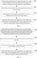
- the setting method for the air-conditioning machine room may include the following steps, S102, S104, S106 and S 108.
- a specification of the chiller unit is determined based on a cooling load of a building, where the specification of the chiller unit includes an inlet and outlet specification and a pipe diameter.
- the cooling load of the building may be understood as a cooling capacity required by the building containing the air-conditioning machine room.
- the machine room in this embodiment may be a machine room equipped with a central air-conditioning system, where the air-conditioning machine room may include the chiller unit, the water pump, and the valve member; the water pump may include a chilled water pump and a cooling water pump; and the valve member may include a rubber soft connection, a variable diameter, a swing check, a right angle filter, a butterfly valve, a pressure gauge, a drain valve, a heat meter, etc.
- the number and model of the equipment and valve member in the air-conditioning machine room are not limited in this embodiment.
- multiple chiller units may be arranged in the air-conditioning machine room, and the models of the chiller units may be different.
- a unit model, a cooling capacity, a system temperature difference and other parameters of the chiller unit are obtained. These parameters may be obtained from the nameplate and instructions of the chiller unit. Based on these parameters, the inlet and outlet specification and the pipe diameter of the chiller unit may be calculated, as the specification of the chiller unit. And then, an appropriate chiller unit pipelines may be selected based on the above calculation results.
- step S104 a specification of the water pump is obtained based on a preset system water flow.
- the water pump in the air-conditioning machine room may include a chilled water pump and a cooling water pump. Specifications of these two types of water pumps are determined in a similar way and will be explained here. First of all, the air-conditioning machine room in this embodiment may include the above two types of water pumps, or may include only one type of water pump, or even neither type of water pumps. If it is determined in this step that the above two types of water pumps are not included, then it may be determined that the specification of the water pump is empty.
- a water flow of a machine room system is obtained, and then a water pump of appropriate model and specification is obtained based on the water flow. If the water flow is small, then a water pump having a small pump body and a small footprint may be selected, such as a vertical single stage pump; if the water flow is large, then a water pump having a large pump body and a large footprint may be selected such as a horizontal double suction pump.
- step S106 a valve member is determined, where a specification of the valve member is matched with the pipe diameter.
- the valve member for the chiller unit may be determined.
- the specification of the valve member for the chiller unit need to match the pipe diameter of the chiller unit.
- the specification of the valve member for the chiller unit and the pipe diameter of the chiller unit may be matched by looking up a size specification table of various valve members. For example, Taking the check valve as an example, a nominal diameter of the check valve (that is, the specification of the check valve) that matches the pipe diameter of each connection pipe of the chiller unit may be looked up in a standard specification size table of the check valve. Based on a look-up result, an appropriate check valve can be selected.
- step S108 the chiller unit, the water pump and the valve member are plotted on a design layout, and the chiller unit, the water pump and valve member are connected; where the chiller unit, the water pump and the valve member are scaled according to the specifications.
- the chiller unit, the water pump and the valve member may be plotted on the design layout.
- the design layout may be plotted using different software, such as an AutoCAD (Autodesk Computer Aided Design) software.
- AutoCAD Autodesk Computer Aided Design
- the chiller unit, the water pump and the valve member are scaled according to the specifications when plotting, which may ensure that the spatial position relationship of the machine room can be intuitively reflected when the air-conditioning machine room is laid out.
- the chiller unit, water pump and valve member need to be connected.
- the chiller unit and the water pump may be connected in a direct connection manner to improve the efficiency of the water pump.
- the chiller unit, the water pump and the valve member are scaled for plotting, and are connected after the specifications of the chiller unit, water pump and valve member are determined.
- the designed air-conditioning machine room has strong adaptability and is convenient to use.
- the embodiment of the present disclosure provides another setting method for an air-conditioning machine room. This method is implemented on the basis of the above embodiment.
- the air-conditioning machine room in this embodiment may include a chiller unit, a cooling water pump, a chilled water pump, a rubber soft connection, a variable diameter, a swing check, a right-angle filter, a butterfly valve, a pressure gauge, a drain valve, a heat meter and other equipment and a valve member.
- FIG. 2 is a flow chart of another setting method for an air-conditioning machine room.
- the setting method for the air-conditioning machine room in this embodiment may include the following steps S202, S204, S206 and S208.
- step S202 a unit model, a cooling capacity and a system temperature difference of the chiller unit are determined based on a cooling load of a building; a branch pipe diameter and a main pipe diameter of the chiller unit are calculated based on the unit model, the cooling capacity and the system temperature difference; and the branch pipe diameter and the main pipe diameter of the chiller unit are adjusted based on a preset flow rate of an air-conditioning water pipe.
- a correspondence relationship between the cooling load of the building and the cooling capacity of the chiller unit may be stored in advance. After the cooling load of the building is determined, the cooling capacity of the chiller unit can be determined based on the above correspondence relationship. In addition, a correspondence relationship between the cooling load of the building and the unit model of the chiller unit may also be stored in advance. After the cooling load of the building is determined, the unit model of the chiller unit can be determined based on the above correspondence relationship, and then the cooling capacity of the unit model may be determined by using other methods.
- the unit model of the chiller unit may be obtained from the nameplate of the chiller unit, and the cooling capacity of the chiller unit may also be obtained from the nameplate of the chiller unit. If the chiller unit's nameplate does not indicate the cooling capacity of the chiller unit, then a water tank volume and a performance coefficient of the chiller unit may be obtained from the nameplate first.
- the performance coefficient is generally a COP (energy efficiency ratio, Coefficient of Performance). Then, a specified time corresponding to a rise of the chiller unit to a specified temperature is measured, and the cooling capacity of the chiller unit is calculated through the following formula, the water tank volume ⁇ the specified temperature ⁇ the specified time ⁇ the performance coefficient.
- the system temperature difference of the chiller unit may be understood as a difference in cooling water temperature, that is, the difference between a cooling water inlet temperature and a cooling water outlet temperature. Also, the system temperature difference may generally be read from the nameplate or instructions of the chiller unit.
- the branch pipe diameter and the main pipe diameter of the chiller unit may be calculated based on the unit model, the cooling capacity and the system temperature difference. Among them, the branch pipe diameter and the main pipe diameter obtained through calculation need to meet an economic flow rate requirement of the air-conditioning water pipe. If the branch pipe diameter and the main pipe diameter obtained through calculation fail to meet the economic flow rate requirement of the air-conditioning water pipe, then the branch pipe diameter and the main pipe diameter of the chiller unit need to be adjusted according to the flow rate requirement of the air-conditioning water pipe.
- step S204 a specification of the water pump is determined based on a preset system water flow.
- Water pumps of different specifications have different characteristics. Among them, a factor of the system water flow should be considered when determining the specification of the water pump. For example, in the case that the preset system water flow is smaller than a preset flow threshold, then the water pump is determined to be a vertical single-stage pump; and in the case that the system water flow is greater than or equal to the flow threshold, then the water pump is determined to be a horizontal double-suction pump.
- a vertical single-stage pipeline pump may be selected, which has the characteristics of a small pump body and a small footprint; if the system water flow is ⁇ 300m 3 /h, then a horizontal double-suction pump may be selected, this type of water pump may be suitable for a machine room systems having a large water flow and has a high efficiency.
- step S206 the valve member is determined, where a specification of the valve member is matched with the pipe diameter.
- the valve member whose specification matching the pipe diameter may be determined according to the pipe diameter of the chiller unit determined in the above step.
- correspondence relationships between different types of valve member and the pipe diameter of the chiller unit may be different.
- the following steps may be performed, including: determining a type of valve member and a correspondence relationship between this type of valve member and the pipe diameter of the chiller unit; and determining the valve member that matches the pipe diameter based on the correspondence relationship.
- the valve member may include, a check valve, a rubber soft connection and a right-angle filter.
- a low-resistance pipeline valve may be used; and correspondingly a swing check valve may be selected as the check valve, which can reduce the energy consumption of the machine room system.
- FIG. 1 shows a standard size specification table of the check valve.
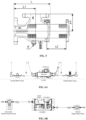
- the check valve may include a valve body 31, a valve flap 32 and a valve cover 33.
- the specification of the check valve includes a nominal diameter, L1, D1 and N- ⁇ d.
- the check valve having a suitable nominal diameter may be selected based on the pipe diameter of the chiller unit calculated in the previous step, and it is determined whether the parameters such as L1, D1 and N- ⁇ d of the check valve of this nominal diameter are appropriate.
- Table 2 is a standard size specification table of the rubber soft connection (also referred to as a rubber hose).
- the specification of rubber soft connection includes a nominal diameter, L1, an axial displacement (including an elongation and a compression), a lateral displacement and an offset angle.
- the rubber soft connection having a suitable nominal diameter may be selected according to the pipe diameter of the chiller unit calculated in the previous step, and it is determined whether the parameters such as L1, the axial displacement (including the elongation and the compression), the lateral displacement and the offset angle of the rubber soft connection of this nominal diameter are appropriate.
- Table 3 is a standard size specification table of the right-angle filter.
- the specification of the right-angle filter includes an inlet, an outlet, L, L1, L2, H1, d and other parameters.
- the right-angle filter having a suitable specification may be obtained based on the pipe diameter of the chiller unit calculated in the previous steps.
- step S208 the chiller unit, the water pump and the valve member are plotted on a design layout, and the chiller unit, the water pump and the valve member are connected; where, the chiller unit, the water pump and the valve member are scaled according to the specifications.
- drawing blocks may be created for all valve members in CAD according to a drawing scale, and can be adapted to various types of chiller units and pipe diameters.
- the water pump in the embodiment of the present disclosure may include a chilled water pump and a cooling water pump.
- the chilled water pump is coupled to the chiller unit through a freezing pipe; the cooling water pump is coupled to the chiller unit through a cooling pipe.
- the freezing pipe and the cooling pipe are arranged on the same side of the chiller unit; or alternatively, the freezing pipe and the cooling pipe are arranged on opposite sides of the chiller unit.
- the arrangement of freezing pipe and cooling pipe entering and exiting on the same side or from different sides may be selected according to an area of the air-conditioning machine room. For example, the area of the air-conditioning machine room is determined; if the area is greater than a preset area threshold, then the freezing pipe and cooling pipe are arranged on opposite sides of the chiller unit; and if the area is smaller than or equal to the area threshold, the freezing pipe and the cooling pipe are arranged on the same side of the chiller unit.
- the arrangement of the freezing pipe and cooling pipe entering and exiting from different sides may be suitable for a layout of larger air-conditioning machine room.
- the arrangement of the freezing pipe and cooling pipe entering and exiting on the same side may be selected.
- FIG. 6A and FIG. 6B show respectively a cross-sectional view and a top view of an arrangement of the water pump and the chiller unit where the freezing pipe and the cooling pipe enter and exit from different sides for.
- CCWF400EV is the chiller unit
- the cooling water pump is provided on the left side of the chiller unit
- the chilled water pump is provided on the right side of the chiller unit.
- the cooling water pump adopts a horizontal double-suction pump
- the chilled water pump adopts a vertical pipeline pump.
- the freezing pipe is arranged on the right side of the chiller unit
- the cooling pipe is arranged on the left side of the chiller unit. The freezing pipe and the cooling pipe enter and exit from different sides.
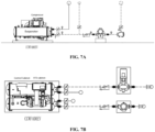
- FIG. 7A and FIG. 7B show respectively a cross-sectional view and a top view of an arrangement of the water pump and the chiller unit where the freezing pipe and the cooling pipe enter and exit on the same side.
- the CCWF400EV is the chiller unit
- the cooling water pump and the cooling water pump are provided on the left side of the chiller unit.
- the freezing pipe and the cooling pipe are both provided on the right side of the chiller unit, and the freezing pipe and the cooling pipe enter and exit on the same side.
- chiller unit and water pump may be connected in a direct connection manner.
- the direct connection can improve the efficiency of the water pump, while also reducing right-angle elbows in the pipeline and reducing the system resistance.
- the above methods provided by the embodiments of the present disclosure provide a standard layout type for an efficient machine room, which can be directly arranged in a relevant machine room drawing using standardized layout blocks, and this layout type has a minimum usable area while ensuring the normal construction and connection of the units, and the pipelines between equipment connections may also be lengthened to meet the layout of a larger machine room.
- the chiller unit and the water pump are directly connected, which can improve the efficiency of the water pump, while also reducing the right-angle elbows in the pipeline and reducing the system resistance.
- a swing check valve in low force, a right-angle filter and other low-resistance pipeline valve are used, which effectively reduces the energy consumption of the system.
- the specifications and dimensions of each equipment and valve in the machine room system are scaled in proportional for plotting to ensure that the machine room layout can intuitively reflect the spatial position relationship of the machine room; and this standard layout takes into account a piping space of the connection pipe and the backup pump, which is highly applicable and convenient to use.
- a setting device for an air-conditioning machine room provided according to the embodiments of the present disclosure will be described in detail below with reference to the accompanying drawings.
- an embodiment of the present disclosure provides a setting device for an air-conditioning machine room.
- the air-conditioning machine room may include: a chiller unit, a water pump and a valve member.
- the setting devices of the air-conditioning machine room may include: a chiller unit specification determination module 81, a water pump specification determination module 82, a valve member specification determination module 83 and an equipment plotting connection module 84.
- the chiller unit specification determination module 81 is configured to determine a specification of the chiller unit based on a cooling load of a building; wherein the specification of the chiller unit includes an inlet and outlet specification and a pipe diameter.
- the water pump specification determination module 82 is configured to determine a specification of the water pump based on a preset system water flow.
- the valve member specification determination module 83 is configured to determine a valve member whose specification matching the pipe diameter.
- the equipment plotting connection module 84 is configured to plot the chiller unit, the water pump and the valve member on the design layout, and connect the chiller unit, the water pump and the valve member; where, the chiller unit, the water pump and the valve member are scaled according to the specifications.
- the chiller unit, the water pump, and the valve member are scaled for plotting, and are connected after the specifications of the chiller unit, the water pump, and the valve member are determined.
- the designed air-conditioning machine room has strong adaptability and is convenient to use.
- the pipe diameter of the above-mentioned takeover may include a branch pipe diameter and a main pipe diameter.
- the above-mentioned chiller unit specification determination module may be configured to: determine a unit model, a cooling capacity and a system temperature difference of the chiller unit based on the cooling load of the building; calculate the branch pipe diameter and the main pipe diameter of the chiller unit based on the unit model, the cooling capacity and the system temperature difference; and adjust the branch pipe diameter and the main pipe diameter of the chiller unit based on a preset flow rate of an air-conditioning water pipe.
- the above-mentioned water pump specification determination module may be configured to: determine that the water pump is a vertical single-stage pump if the preset system water flow is smaller than a preset flow threshold; and determining that the water pump is a horizontal double-suction pump if the system water flow is greater than or equal to the flow threshold.
- the above-mentioned valve member specification determination module may be configured to: determine a type of valve member and a correspondence relationship between the type of valve member and the pipe diameter of the chiller unit; and determine the valve member that matches the pipe diameter based on the correspondence relationship.
- the valve member may include a check valve, a rubber soft connection, and a right-angle filter.
- the above-mentioned valve member may be a low-resistance pipeline valve.
- the check valve may be a swing check valve.
- the above-mentioned equipment plotting connection module may be configured to connect the chiller unit and the water pump in a direct connection manner.
- the above-mentioned water pump may include a chilled water pump and a cooling water pump.
- the chilled water pump is coupled to the chiller unit through a freezing pipe; the cooling water pump is coupled to the chiller unit through a cooling pipe.
- the above-mentioned equipment plotting connection module may be configured to, arrange the freezing pipe and the cooling pipe on the same side of the chiller unit; or alternatively, arrange the freezing pipe and cooling pipe on opposite sides of the chiller unit.
- the above-mentioned equipment plotting connection module may be configured to determine an area of the air-conditioning machine room, and arrange the freezing pipe and the cooling pipe on opposite sides of the chiller unit if the area is greater than a preset area threshold.
- the above-mentioned equipment plotting connection module may be configured to arrange the freezing pipe and the cooling pipe on the same side of the chiller unit if the area is smaller than or equal to the area threshold.
- An embodiment of the present disclosure also provides a piece of electronic equipment, which may be configured to perform the above-mentioned setting method for the air-conditioning machine room.
- a schematic structural diagram of a piece of electronic equipment is shown.
- the electronic equipment may include a memory 100 and a processor 101, where the memory 100 is configured to store one or more computer instructions, and the one or more computer instructions, when executed by the processor 101, enable the above-mentioned setting method for the air-conditioning machine room to be implemented.
- the electronic equipment shown in FIG. 9 may also include a bus 102 and a communication interface 103.
- the processor 101, the communication interface 103 and the memory 100 are connected through the bus 102.
- the memory 100 may include a high-speed random-access memory (RAM, Random Access Memory), and may also include a non-volatile memory (non-volatile memory), such as at least one disk memory.
- the communication connection between the system network element and at least one other network element is realized through at least one communication interface 103 (which may be wired or wireless), and the Internet, wide area network, local network, metropolitan area network, etc. may be used.
- the bus 102 may be an ISA bus, a PCI bus, an EISA bus, etc.
- the bus may be divided into an address bus, a data bus, a control bus, etc. For ease of presentation, only one bidirectional arrow is shown in FIG. 9 , but it does not mean that there is only one bus or one type of bus.
- the processor 101 may be an integrated circuit chip having signal processing capabilities. During the implementation process, each step of the above method may be completed by instructions in the form of hardware integrated logic circuits or software in the processor 101.
- the above-mentioned processor 101 may be a general-purpose processor, including a central processing unit (Central Processing Unit, CPU for short), a network processor (Network Processor, NP for short), etc.
- the processor may also be a digital signal processor (Digital Signal Processor, DSP for short), an application specific integrated circuit (Application Specific Integrated Circuit, ASIC for short), a field-programmable gate array (Field-Programmable Gate Array, FPGA for short) or other programmable logic devices, a discrete gate or a transistor logic device, and a discrete hardware component.
- a general-purpose processor may be a microprocessor or the processor may be any conventional processor, etc.
- the steps of the method disclosed in conjunction with the embodiments of the present disclosure may be directly implemented by a hardware decoding processor, or executed by a combination of hardware and software modules in the decoding processor.
- the software module may be inserted in a random-access memory, a flash memory, a read-only memory, a programmable read-only memory or an electrically erasable programmable memory, a register and other mature storage media in this field.
- the storage medium is stored in the memory 100.
- the processor 101 reads the information in the memory 100 and implement the steps of the method in the foregoing embodiment in combination with the hardware.
- Embodiments of the present disclosure also provide a computer-readable storage medium.
- the computer-readable storage medium may store a computer-executable instructions.
- the computer-executable instruction When invoked and executed by the processor, the computer-executable instruction causes the processor to implement the above setting method for an air-conditioning machine room, for specific implementation, references may be made to the method embodiments, which will not be described again here.
- a computer program product for the setting method for the air-conditioning machine room, the device and the electronic equipment is provided by an embodiment of the present disclosure.
- the computer program product may include a computer-readable storage medium storing a program code.
- the instructions included in the program code may be used to execute the method in the preceding embodiments, for specific implementation, reference may be made to the method embodiments, which will not be described again here.
- connection should be understood in a broad sense.
- it may be a fixed connection or a detachable connection, or it may be integrally connected; it may be a mechanical connection or an electrical connection; it may be a direct connection or an indirect connection through an intermediate medium; and it may be an internal connection between two components.
- connection may be a fixed connection or a detachable connection, or it may be integrally connected; it may be a mechanical connection or an electrical connection; it may be a direct connection or an indirect connection through an intermediate medium; and it may be an internal connection between two components.
- the technical solution of the present disclosure is essentially or the part that contributes to the relevant technology or the part of the technical solution may be embodied in the form of a software product.
- the computer software product is stored in a storage medium and includes several instructions that are configured to cause a computer device (which may be a personal computer, a server, or a network device, etc.) to execute all or part of the steps of the methods described in various embodiments of the present disclosure.
- the aforementioned storage medium includes: a U disk, a mobile hard disk, a read-only memory (ROM, Read-Only Memory), a random-access memory (RAM, Random Access Memory), a magnetic disk or an optical disk and other media that can store a program code.
- orientation or positional relationship indicated by terms such as “center”, “upper”, “lower”, “left”, “right”, “vertical”, “horizontal”, “inner”, “outer”, etc. is based on the orientation or positional relationship shown in the drawings, which is only for the convenience of describing the present disclosure and simplifying the description, and does not intended to indicate or imply that the device or element referred to must have a specific orientation or be constructed or operated in a specific orientation, and therefore should not be construed as limitations on the present disclosure.
- the terms “first”, “second” and “third” are used for descriptive purposes only and should not be construed as indicating or implying relative importance.
- the present disclosure provides a setting method for an air-conditioning machine room, a device, electronic equipment and a readable storage medium.
- the method includes steps of: determining a specification of a chiller unit based on a cooling load of a building; where the specification of the chiller unit include an inlet and outlet specification and a pipe diameter; determining a specification of a water pump based on a preset system water flow; determining a valve member, where a specification of the valve member is matched with the pipe diameter; and plotting the chiller unit, the water pump and the valve member on a design layout, and connecting the chiller unit, the water pump and the valve member; where, the chiller unit, the water pump and the valve member are scaled according to the specifications.
- the chiller unit, the water pump and the valve member are scaled for plotting, and are connected, this ensures that the spatial location relationship of the machine room can be intuitively reflected when the air-conditioning machine room is laid out.
- the designed air-conditioning machine room is highly adaptable and convenient to use.
- the setting method for the air-conditioning machine room, the device, the electronic equipment and the readable storage medium of the present disclosure are reproducible and can be applied in various applications.
- the setting method for the air-conditioning machine room, the device, the electronic equipment and the readable storage medium of the present disclosure may be applied to the field of air-conditioning technology, etc.
Landscapes
- Engineering & Computer Science (AREA)
- Physics & Mathematics (AREA)
- Geometry (AREA)
- Theoretical Computer Science (AREA)
- General Physics & Mathematics (AREA)
- Computer Hardware Design (AREA)
- Evolutionary Computation (AREA)
- Mathematical Optimization (AREA)
- Pure & Applied Mathematics (AREA)
- Mathematical Analysis (AREA)
- Computational Mathematics (AREA)
- General Engineering & Computer Science (AREA)
- Computer Networks & Wireless Communication (AREA)
- Architecture (AREA)
- Civil Engineering (AREA)
- Structural Engineering (AREA)
- Air Conditioning Control Device (AREA)
Abstract
Description
- This application claims the priority of the
Chinese Patent Application No. 202111092475.4 filed with the China Patent Office on September 17, 2021 - The present disclosure relates to the field of air-conditioning technology, and in particular, to a setting method for an air-conditioning machine room, a device, electronic equipment, and a readable storage medium.
- In related technologies, the design of a machine room system of central air-conditioning has complicated and chaotic layout of pipelines, which may lead to problems such as crowded locations and pipeline crossings, which then increases the space requirement of the machine room and the pipeline resistance of the system, increases the energy consumption of the machine room system, and cannot intuitively reflect the spatial location relationships of the machine room. The designed machine room has poor adaptability.
- The present disclosure provides a setting method for an air-conditioning machine room, a device, electronic equipment and a readable storage medium, to at least ensure that the spatial positional relationship of the machine room can be intuitively reflected during the layout of the machine room. The designed machine room has strong adaptability and is convenient to use.
- In accordance with some embodiments of the present disclosure, a setting method for an air-conditioning machine room is provided. The air-conditioning machine room may include, a chiller unit, a water pump and a valve member. The method may include steps of: determining a specification of the chiller unit based on a cooling load of a building, where, the specification of the chiller unit includes, an inlet and outlet specification and a pipe diameter; determining a specification of the water pump based on a preset system water flow; determining a valve member, where a specification of the valve member is matched with the pipe diameter; and plotting the chiller unit, the water pump and valve member on a design layout, and connecting the chiller unit, the water pump and the valve member, where, the chiller unit, the water pump and the valve member are scaled according to the specifications.
- In accordance with some embodiments of the present disclosure, a setting device for an air-conditioning machine room is provided. The air-conditioning machine room may include a chiller unit, a water pump, and a valve member. The setting device may include: a chiller unit specification determination module which is configured to determine a specification of the chiller unit based on a preset flow rate of an air-conditioning water pipe, where the specification of the chiller unit includes an inlet and outlet specification and a pipe diameters; a water pump specification determination module which is configured to determine a specification of the water pump based on a preset system water flow; a valve member specification determination module which is configured to determine the valve member whose specification matches the pipe diameter; and an equipment plotting connection module which is configured to plot the chiller unit, the water pump and the valve member on a design layout, and connect the chiller unit, the water pump and the valve member, where, the chiller unit, the water pump and the valve member are scaled according to the specifications.
- In accordance with some embodiments of the present disclosure, a piece of electronic equipment is provided. The electronic equipment may include a processor and a memory. The memory stores a computer-executable instruction that is executable by the processor. The processor, when executing the computer-executable instruction, is configured to implement the above-mentioned setting method for the air-conditioning machine room.
- In accordance with some embodiments of the present disclosure, a computer-readable storage medium is provided, in which a computer-executable instruction is stored. The computer-executable instruction, when invoked and executed by a processor, causes the processor to implement the above-mentioned setting method for the air-conditioning machine room.
- Other features and advantages of the present disclosure will be set forth in the subsequent description, or some of the features and advantages may be inferred or unambiguously determined from the description, or may be learned by practicing the above-mentioned techniques of the present disclosure.
- In order to make the above-mentioned objectives, features and advantages of the present disclosure more obvious and comprehensible, preferred embodiments are given below and described in detail with reference to the accompanying drawings.
- In order to explain the technical solutions in the specific embodiments of the present disclosure or related technologies more clearly, the drawings that need to be used in the description of the specific embodiments or related technologies will be briefly introduced below. Obviously, the drawings in the following description are some embodiments of the present disclosure, those of ordinary skill in the art can also obtain other drawings based on these drawings without exerting creative efforts.
-
FIG. 1 is a flow chart of a setting method for an air-conditioning machine room according to some embodiments of the present disclosure; -
FIG. 2 is a flow chart of another setting method for an air-conditioning machine room provided by some embodiments of the present disclosure; -
FIG. 3 is a schematic diagram of a check valve provided by some embodiments of the present disclosure; -
FIG. 4 is a schematic diagram of a rubber soft connection provided by some embodiments of the present disclosure; -
FIG. 5 is a schematic diagram of a right-angle filter provided by some embodiments of the present disclosure; -
FIG. 6A and FIG. 6B show respectively a cross-sectional view and a top view of an arrangement of a water pump and a chiller unit where a freezing pipe and a cooling pipe enter and exit from different sides according to some embodiments of the present disclosure; -
FIG. 7A and FIG. 7B show respectively a cross-sectional view and a top view of an arrangement of the water pump and the chiller unit where the freezing pipe and the cooling pipe enter and exit on the same side according to some embodiments of the present disclosure; -
FIG. 8 is a schematic structural diagram of a setting device for an air-conditioning machine room according to some embodiments of the present disclosure; and -
FIG. 9 is a schematic structural diagram of a piece of electronic equipment provided by some embodiments of the present disclosure. - 31 - valve body; 32 - valve flap; 33 - valve cover; 81- chiller unit specification determination module; 82 - water pump specification determination module; 83 - valve member specification determination module; 84 - equipment plotting connection module; 100 - memory; 101 - processor; 102 - bus; and 103 - communication interface.
- In order to make the purpose, technical solutions and advantages of the embodiments of the present disclosure much clearer, the technical solutions of the present disclosure will be clearly and completely described below in conjunction with the drawings. Obviously, the described embodiments are some embodiments of the present disclosure, not all embodiments of the present disclosure. Based on the embodiments in this disclosure, all other embodiments obtained by those of ordinary skill in the art without exerting creative efforts shall fall within the protection scope of this disclosure.
- At present, in the related technologies, the design of the machine room system of central air-conditioning has complicated and chaotic layout of pipelines, which may lead to the problems of crowded locations and pipeline crossings, which then increases the space requirements of the machine room and the pipeline resistance of the system, increases the energy consumption of the machine room system, and cannot intuitively reflect the spatial location relationships of the machine room. The designed machine room has poor adaptability and is difficult to use.
- On basis of this, embodiments of the present disclosure provide a setting method for an air-conditioning machine room, a device, electronic equipment, and a readable storage medium. Particularly, the present disclosure relates to a standard layout type of an efficient machine room, which enables a convenient and quick layout of the machine room, and has a compact space structure, while reducing the pipeline resistance of the system and improving the overall energy efficiency of the system.
- A setting method for an air-conditioning machine room provided according to embodiments of the present disclosure will be described in detail below with reference to the accompanying drawings.
- An embodiment of the present disclosure provides a setting method for an air-conditioning machine room. The air-conditioning machine room may include, a chiller unit, a water pump and a valve member. Referring to the flow chart of the setting method for the air-conditioning machine room shown in
FIG. 1 , the setting method for the air-conditioning machine room may include the following steps, S102, S104, S106 and S 108. - In step S102, a specification of the chiller unit is determined based on a cooling load of a building, where the specification of the chiller unit includes an inlet and outlet specification and a pipe diameter.
- In this embodiment, the cooling load of the building may be understood as a cooling capacity required by the building containing the air-conditioning machine room. The machine room in this embodiment may be a machine room equipped with a central air-conditioning system, where the air-conditioning machine room may include the chiller unit, the water pump, and the valve member; the water pump may include a chilled water pump and a cooling water pump; and the valve member may include a rubber soft connection, a variable diameter, a swing check, a right angle filter, a butterfly valve, a pressure gauge, a drain valve, a heat meter, etc.
- In addition, the number and model of the equipment and valve member in the air-conditioning machine room are not limited in this embodiment. For example, multiple chiller units may be arranged in the air-conditioning machine room, and the models of the chiller units may be different.
- During a determination of the specification of the chiller unit in the machine room, firstly, a unit model, a cooling capacity, a system temperature difference and other parameters of the chiller unit are obtained. These parameters may be obtained from the nameplate and instructions of the chiller unit. Based on these parameters, the inlet and outlet specification and the pipe diameter of the chiller unit may be calculated, as the specification of the chiller unit. And then, an appropriate chiller unit pipelines may be selected based on the above calculation results.
- In step S104, a specification of the water pump is obtained based on a preset system water flow.
- The water pump in the air-conditioning machine room may include a chilled water pump and a cooling water pump. Specifications of these two types of water pumps are determined in a similar way and will be explained here. First of all, the air-conditioning machine room in this embodiment may include the above two types of water pumps, or may include only one type of water pump, or even neither type of water pumps. If it is determined in this step that the above two types of water pumps are not included, then it may be determined that the specification of the water pump is empty.
- During a determination of the specification of the water pump in the machine room, firstly, a water flow of a machine room system is obtained, and then a water pump of appropriate model and specification is obtained based on the water flow. If the water flow is small, then a water pump having a small pump body and a small footprint may be selected, such as a vertical single stage pump; if the water flow is large, then a water pump having a large pump body and a large footprint may be selected such as a horizontal double suction pump.
- In step S106, a valve member is determined, where a specification of the valve member is matched with the pipe diameter.
- After the specifications of the chiller unit and water pump in the machine room are determined, the valve member for the chiller unit may be determined. The specification of the valve member for the chiller unit need to match the pipe diameter of the chiller unit. Particularly, the specification of the valve member for the chiller unit and the pipe diameter of the chiller unit may be matched by looking up a size specification table of various valve members. For example, Taking the check valve as an example, a nominal diameter of the check valve (that is, the specification of the check valve) that matches the pipe diameter of each connection pipe of the chiller unit may be looked up in a standard specification size table of the check valve. Based on a look-up result, an appropriate check valve can be selected.
- In step S108, the chiller unit, the water pump and the valve member are plotted on a design layout, and the chiller unit, the water pump and valve member are connected; where the chiller unit, the water pump and the valve member are scaled according to the specifications.
- After the specifications of the chiller unit, the water pump and the valve member are determined, the chiller unit, the water pump and the valve member may be plotted on the design layout. The design layout may be plotted using different software, such as an AutoCAD (Autodesk Computer Aided Design) software. In this step, the chiller unit, the water pump and the valve member are scaled according to the specifications when plotting, which may ensure that the spatial position relationship of the machine room can be intuitively reflected when the air-conditioning machine room is laid out.
- After the plotting of the chiller unit, water pump and valve member is completed, the chiller unit, water pump and valve member need to be connected. In this step, the chiller unit and the water pump may be connected in a direct connection manner to improve the efficiency of the water pump.
- In the setting method for the air-conditioning machine room provided by the embodiment of the present disclosure, the chiller unit, the water pump and the valve member are scaled for plotting, and are connected after the specifications of the chiller unit, water pump and valve member are determined. Thus, it is ensured the spatial location relationship of the machine room can be intuitively reflected during the layout of the air-conditioning machine room. The designed air-conditioning machine room has strong adaptability and is convenient to use.
- Another setting method for an air-conditioning machine room according to an embodiment of the present disclosure will be described in detail below with reference to the accompanying drawings.
- The embodiment of the present disclosure provides another setting method for an air-conditioning machine room. This method is implemented on the basis of the above embodiment. The air-conditioning machine room in this embodiment may include a chiller unit, a cooling water pump, a chilled water pump, a rubber soft connection, a variable diameter, a swing check, a right-angle filter, a butterfly valve, a pressure gauge, a drain valve, a heat meter and other equipment and a valve member.
- Based on the above description, as shown in
FIG. 2 is a flow chart of another setting method for an air-conditioning machine room. The setting method for the air-conditioning machine room in this embodiment may include the following steps S202, S204, S206 and S208. - In step S202, a unit model, a cooling capacity and a system temperature difference of the chiller unit are determined based on a cooling load of a building; a branch pipe diameter and a main pipe diameter of the chiller unit are calculated based on the unit model, the cooling capacity and the system temperature difference; and the branch pipe diameter and the main pipe diameter of the chiller unit are adjusted based on a preset flow rate of an air-conditioning water pipe.
- Where, a correspondence relationship between the cooling load of the building and the cooling capacity of the chiller unit may be stored in advance. After the cooling load of the building is determined, the cooling capacity of the chiller unit can be determined based on the above correspondence relationship. In addition, a correspondence relationship between the cooling load of the building and the unit model of the chiller unit may also be stored in advance. After the cooling load of the building is determined, the unit model of the chiller unit can be determined based on the above correspondence relationship, and then the cooling capacity of the unit model may be determined by using other methods.
- For example, the unit model of the chiller unit may be obtained from the nameplate of the chiller unit, and the cooling capacity of the chiller unit may also be obtained from the nameplate of the chiller unit. If the chiller unit's nameplate does not indicate the cooling capacity of the chiller unit, then a water tank volume and a performance coefficient of the chiller unit may be obtained from the nameplate first. The performance coefficient is generally a COP (energy efficiency ratio, Coefficient of Performance). Then, a specified time corresponding to a rise of the chiller unit to a specified temperature is measured, and the cooling capacity of the chiller unit is calculated through the following formula, the water tank volume × the specified temperature ÷ the specified time ÷ the performance coefficient.
- The system temperature difference of the chiller unit may be understood as a difference in cooling water temperature, that is, the difference between a cooling water inlet temperature and a cooling water outlet temperature. Also, the system temperature difference may generally be read from the nameplate or instructions of the chiller unit.
- The branch pipe diameter and the main pipe diameter of the chiller unit may be calculated based on the unit model, the cooling capacity and the system temperature difference. Among them, the branch pipe diameter and the main pipe diameter obtained through calculation need to meet an economic flow rate requirement of the air-conditioning water pipe. If the branch pipe diameter and the main pipe diameter obtained through calculation fail to meet the economic flow rate requirement of the air-conditioning water pipe, then the branch pipe diameter and the main pipe diameter of the chiller unit need to be adjusted according to the flow rate requirement of the air-conditioning water pipe.
- In step S204, a specification of the water pump is determined based on a preset system water flow.
- Water pumps of different specifications have different characteristics. Among them, a factor of the system water flow should be considered when determining the specification of the water pump. For example, in the case that the preset system water flow is smaller than a preset flow threshold, then the water pump is determined to be a vertical single-stage pump; and in the case that the system water flow is greater than or equal to the flow threshold, then the water pump is determined to be a horizontal double-suction pump.
- Taking the preset flow threshold of 300m3 /h as an example, if the system water flow is <300m 3 /h, then a vertical single-stage pipeline pump may be selected, which has the characteristics of a small pump body and a small footprint; if the system water flow is ≥300m3 /h, then a horizontal double-suction pump may be selected, this type of water pump may be suitable for a machine room systems having a large water flow and has a high efficiency.
- In step S206, the valve member is determined, where a specification of the valve member is matched with the pipe diameter.
- The valve member whose specification matching the pipe diameter may be determined according to the pipe diameter of the chiller unit determined in the above step. Among them, correspondence relationships between different types of valve member and the pipe diameter of the chiller unit may be different. The following steps may be performed, including: determining a type of valve member and a correspondence relationship between this type of valve member and the pipe diameter of the chiller unit; and determining the valve member that matches the pipe diameter based on the correspondence relationship.
- Where, the valve member may include, a check valve, a rubber soft connection and a right-angle filter. To reduce a pipeline resistance of the machine room system, a low-resistance pipeline valve may be used; and correspondingly a swing check valve may be selected as the check valve, which can reduce the energy consumption of the machine room system.
- Taking the check valve as an example, with reference to the schematic diagram of a check valve shown in
FIG. 3 and Table 1.FIG. 1 shows a standard size specification table of the check valve. The check valve may include avalve body 31, avalve flap 32 and avalve cover 33. As shown inFIG. 3 and Table 1, the specification of the check valve includes a nominal diameter, L1, D1 and N-Φd. During a selection of check valve, the check valve having a suitable nominal diameter may be selected based on the pipe diameter of the chiller unit calculated in the previous step, and it is determined whether the parameters such as L1, D1 and N-Φ d of the check valve of this nominal diameter are appropriate.Table 1 Standard Size Specification Sable of Check Valve Nominal Diameter L1 D1 N-Φd 1.0MPa 1.6MPa 1.0MPa 1.6MPa 50 203 125 125 4-18 4-18 65 216 145 145 4-18 4-18 80 241 160 160 8-18 8-18 100 292 180 180 8-18 8-18 125 330 210 210 8-18 8-18 150 356 240 240 8-22 8-22 200 495 295 295 8-22 12-22 250 622 350 355 12-22 12-22 300 698 400 410 12-22 12-26 350 787 460 470 16-22 16-26 400 914 515 525 16-26 16-30 450 978 565 585 20-26 20-30 500 978 620 650 20-26 20-33 600 1295 725 770 20-30 20-36 - Then, taking the rubber soft connection as an example, with reference to the schematic diagram of a rubber soft connection shown in
FIG. 4 and Table 2. Table 2 is a standard size specification table of the rubber soft connection (also referred to as a rubber hose). As shown inFIG. 4 and Table 2, the specification of rubber soft connection includes a nominal diameter, L1, an axial displacement (including an elongation and a compression), a lateral displacement and an offset angle. During a selection of rubber soft connection, the rubber soft connection having a suitable nominal diameter may be selected according to the pipe diameter of the chiller unit calculated in the previous step, and it is determined whether the parameters such as L1, the axial displacement (including the elongation and the compression), the lateral displacement and the offset angle of the rubber soft connection of this nominal diameter are appropriate.Table 2 Standard Size Specification Table of Rubber Soft Connection Nominal Diameter L1 Axial Displacement Lateral Displacement Offset Angle Elongation Compression 80 135 8 15 12 15° 100 150 10 19 13 15° 125 165 12 19 13 15° 150 180 12 20 14 15° 200 210 16 25 22 15° 250 230 16 25 22 15° 300 245 16 25 22 15° 350 255 16 25 22 15° 400 255 16 25 22 15° 450 255 16 25 22 15° 500 255 16 25 22 15° 600 260 16 25 22 15° 700 260 16 25 22 15° 800 260 16 25 22 15° 900 260 16 25 22 15° - Then, taking the right-angle filter as an example, with reference to the schematic diagram of a right-angle filter shown in
FIG. 5 and Table 3. Table 3 is a standard size specification table of the right-angle filter. As shown inFIG. 5 and Table 3, the specification of the right-angle filter includes an inlet, an outlet, L, L1, L2, H1, d and other parameters. During a selection of right-angle filter, the right-angle filter having a suitable specification may be obtained based on the pipe diameter of the chiller unit calculated in the previous steps.Table 3 Inlet DN 50 DN 65 DN 80 DN 100DN 150 DN 200 DN 250 DN 300 DN 350 DN 400 DN 500 DN 600 Outlet DN 50 DN 65 DN 80 DN 100DN 150 DN 200 DN 250 DN 300 DN 350 DN 400 DN 500 DN 600 L 211 239 268 311 399 496 585 686 751 819 950 1060 L1 130 146 163 195 256 301 354 425 464 491 550 550 L2 103 126 147 170 228 285 360 430 482 525 695 800 H1 102 111 128 152 203 251 291 341 379 402 460 550 d NPT 1/2"-14 NPT 3/4"-14 NPT 1"-11.5 - In step S208, the chiller unit, the water pump and the valve member are plotted on a design layout, and the chiller unit, the water pump and the valve member are connected; where, the chiller unit, the water pump and the valve member are scaled according to the specifications.
- Based on data in the above specification table, drawing blocks may be created for all valve members in CAD according to a drawing scale, and can be adapted to various types of chiller units and pipe diameters.
- The water pump in the embodiment of the present disclosure may include a chilled water pump and a cooling water pump. The chilled water pump is coupled to the chiller unit through a freezing pipe; the cooling water pump is coupled to the chiller unit through a cooling pipe. During a connection of the chiller unit, water pump and valve member, the following two manners are provided for connecting the freezing pipe and the cooling pipe: the freezing pipe and the cooling pipe are arranged on the same side of the chiller unit; or alternatively, the freezing pipe and the cooling pipe are arranged on opposite sides of the chiller unit.
- Where, the arrangement of freezing pipe and cooling pipe entering and exiting on the same side or from different sides may be selected according to an area of the air-conditioning machine room. For example, the area of the air-conditioning machine room is determined; if the area is greater than a preset area threshold, then the freezing pipe and cooling pipe are arranged on opposite sides of the chiller unit; and if the area is smaller than or equal to the area threshold, the freezing pipe and the cooling pipe are arranged on the same side of the chiller unit.
- Where, the arrangement of the freezing pipe and cooling pipe entering and exiting from different sides may be suitable for a layout of larger air-conditioning machine room. In the case that the area of the air-conditioning machine room is too small and the length cannot meet the requirements of entering and exiting from different sides, the arrangement of the freezing pipe and cooling pipe entering and exiting on the same side may be selected.
- Referring to
FIG. 6A and FIG. 6B , which show respectively a cross-sectional view and a top view of an arrangement of the water pump and the chiller unit where the freezing pipe and the cooling pipe enter and exit from different sides for. In the figures, CCWF400EV is the chiller unit, the cooling water pump is provided on the left side of the chiller unit, and the chilled water pump is provided on the right side of the chiller unit. The cooling water pump adopts a horizontal double-suction pump, and the chilled water pump adopts a vertical pipeline pump. The freezing pipe is arranged on the right side of the chiller unit, and the cooling pipe is arranged on the left side of the chiller unit. The freezing pipe and the cooling pipe enter and exit from different sides. - Referring to
FIG. 7A and FIG. 7B , which show respectively a cross-sectional view and a top view of an arrangement of the water pump and the chiller unit where the freezing pipe and the cooling pipe enter and exit on the same side. In the figures, the CCWF400EV is the chiller unit, the cooling water pump and the cooling water pump are provided on the left side of the chiller unit. The freezing pipe and the cooling pipe are both provided on the right side of the chiller unit, and the freezing pipe and the cooling pipe enter and exit on the same side. - In addition, the chiller unit and water pump may be connected in a direct connection manner. The direct connection can improve the efficiency of the water pump, while also reducing right-angle elbows in the pipeline and reducing the system resistance.
- In summary, the above methods provided by the embodiments of the present disclosure provide a standard layout type for an efficient machine room, which can be directly arranged in a relevant machine room drawing using standardized layout blocks, and this layout type has a minimum usable area while ensuring the normal construction and connection of the units, and the pipelines between equipment connections may also be lengthened to meet the layout of a larger machine room.
- In this method, the chiller unit and the water pump are directly connected, which can improve the efficiency of the water pump, while also reducing the right-angle elbows in the pipeline and reducing the system resistance. In the machine room system, a swing check valve in low force, a right-angle filter and other low-resistance pipeline valve are used, which effectively reduces the energy consumption of the system. Meanwhile, the specifications and dimensions of each equipment and valve in the machine room system are scaled in proportional for plotting to ensure that the machine room layout can intuitively reflect the spatial position relationship of the machine room; and this standard layout takes into account a piping space of the connection pipe and the backup pump, which is highly applicable and convenient to use.
- A setting device for an air-conditioning machine room provided according to the embodiments of the present disclosure will be described in detail below with reference to the accompanying drawings.
- Corresponding to the above method embodiment, an embodiment of the present disclosure provides a setting device for an air-conditioning machine room. The air-conditioning machine room may include: a chiller unit, a water pump and a valve member. Referring to
FIG. 8 which shows a schematic structural diagram of a setting device for an air-conditioning machine room, the setting devices of the air-conditioning machine room may include: a chiller unit specification determination module 81, a water pumpspecification determination module 82, a valve memberspecification determination module 83 and an equipment plottingconnection module 84. - The chiller unit specification determination module 81 is configured to determine a specification of the chiller unit based on a cooling load of a building; wherein the specification of the chiller unit includes an inlet and outlet specification and a pipe diameter.
- The water pump
specification determination module 82 is configured to determine a specification of the water pump based on a preset system water flow. - The valve member
specification determination module 83 is configured to determine a valve member whose specification matching the pipe diameter. - The equipment plotting
connection module 84 is configured to plot the chiller unit, the water pump and the valve member on the design layout, and connect the chiller unit, the water pump and the valve member; where, the chiller unit, the water pump and the valve member are scaled according to the specifications. - In the setting device for the air-conditioning machine room provided by the embodiment of the present disclosure, the chiller unit, the water pump, and the valve member are scaled for plotting, and are connected after the specifications of the chiller unit, the water pump, and the valve member are determined. Thus, it is ensured that the spatial location relationship of the machine room can be intuitively reflected during the layout of the air-conditioning machine room. The designed air-conditioning machine room has strong adaptability and is convenient to use.
- The pipe diameter of the above-mentioned takeover may include a branch pipe diameter and a main pipe diameter. The above-mentioned chiller unit specification determination module may be configured to: determine a unit model, a cooling capacity and a system temperature difference of the chiller unit based on the cooling load of the building; calculate the branch pipe diameter and the main pipe diameter of the chiller unit based on the unit model, the cooling capacity and the system temperature difference; and adjust the branch pipe diameter and the main pipe diameter of the chiller unit based on a preset flow rate of an air-conditioning water pipe.
- The above-mentioned water pump specification determination module may be configured to: determine that the water pump is a vertical single-stage pump if the preset system water flow is smaller than a preset flow threshold; and determining that the water pump is a horizontal double-suction pump if the system water flow is greater than or equal to the flow threshold.
- The above-mentioned valve member specification determination module may be configured to: determine a type of valve member and a correspondence relationship between the type of valve member and the pipe diameter of the chiller unit; and determine the valve member that matches the pipe diameter based on the correspondence relationship.
- The valve member may include a check valve, a rubber soft connection, and a right-angle filter. The above-mentioned valve member may be a low-resistance pipeline valve. The check valve may be a swing check valve.
- The above-mentioned equipment plotting connection module may be configured to connect the chiller unit and the water pump in a direct connection manner.
- The above-mentioned water pump may include a chilled water pump and a cooling water pump. The chilled water pump is coupled to the chiller unit through a freezing pipe; the cooling water pump is coupled to the chiller unit through a cooling pipe. The above-mentioned equipment plotting connection module may be configured to, arrange the freezing pipe and the cooling pipe on the same side of the chiller unit; or alternatively, arrange the freezing pipe and cooling pipe on opposite sides of the chiller unit.
- The above-mentioned equipment plotting connection module may be configured to determine an area of the air-conditioning machine room, and arrange the freezing pipe and the cooling pipe on opposite sides of the chiller unit if the area is greater than a preset area threshold. The above-mentioned equipment plotting connection module may be configured to arrange the freezing pipe and the cooling pipe on the same side of the chiller unit if the area is smaller than or equal to the area threshold.
- It can be clearly understood by persons skilled in the art that, for the convenience and simplicity of description, the specific working process of the above-described setting device for the air-conditioning machine room may refer to the corresponding process of the setting method for the air-conditioning machine room in the aforementioned embodiment, which will not be repeated here.
- Electronic equipment provided according to the embodiments of the present disclosure will be described in detail below with reference to the accompanying drawings.
- An embodiment of the present disclosure also provides a piece of electronic equipment, which may be configured to perform the above-mentioned setting method for the air-conditioning machine room. With reference to
FIG. 9 , a schematic structural diagram of a piece of electronic equipment is shown. The electronic equipment may include amemory 100 and aprocessor 101, where thememory 100 is configured to store one or more computer instructions, and the one or more computer instructions, when executed by theprocessor 101, enable the above-mentioned setting method for the air-conditioning machine room to be implemented. - The electronic equipment shown in
FIG. 9 may also include a bus 102 and acommunication interface 103. Theprocessor 101, thecommunication interface 103 and thememory 100 are connected through the bus 102. - Among them, the
memory 100 may include a high-speed random-access memory (RAM, Random Access Memory), and may also include a non-volatile memory (non-volatile memory), such as at least one disk memory. The communication connection between the system network element and at least one other network element is realized through at least one communication interface 103 (which may be wired or wireless), and the Internet, wide area network, local network, metropolitan area network, etc. may be used. The bus 102 may be an ISA bus, a PCI bus, an EISA bus, etc. The bus may be divided into an address bus, a data bus, a control bus, etc. For ease of presentation, only one bidirectional arrow is shown inFIG. 9 , but it does not mean that there is only one bus or one type of bus. - The
processor 101 may be an integrated circuit chip having signal processing capabilities. During the implementation process, each step of the above method may be completed by instructions in the form of hardware integrated logic circuits or software in theprocessor 101. The above-mentionedprocessor 101 may be a general-purpose processor, including a central processing unit (Central Processing Unit, CPU for short), a network processor (Network Processor, NP for short), etc. The processor may also be a digital signal processor (Digital Signal Processor, DSP for short), an application specific integrated circuit (Application Specific Integrated Circuit, ASIC for short), a field-programmable gate array (Field-Programmable Gate Array, FPGA for short) or other programmable logic devices, a discrete gate or a transistor logic device, and a discrete hardware component. Each method, step and logical block diagram disclosed in the embodiments of the present disclosure can be implemented or executed. A general-purpose processor may be a microprocessor or the processor may be any conventional processor, etc. The steps of the method disclosed in conjunction with the embodiments of the present disclosure may be directly implemented by a hardware decoding processor, or executed by a combination of hardware and software modules in the decoding processor. The software module may be inserted in a random-access memory, a flash memory, a read-only memory, a programmable read-only memory or an electrically erasable programmable memory, a register and other mature storage media in this field. The storage medium is stored in thememory 100. Theprocessor 101 reads the information in thememory 100 and implement the steps of the method in the foregoing embodiment in combination with the hardware. - Embodiments of the present disclosure also provide a computer-readable storage medium. The computer-readable storage medium may store a computer-executable instructions. When the computer-executable instruction is invoked and executed by the processor, the computer-executable instruction causes the processor to implement the above setting method for an air-conditioning machine room, for specific implementation, references may be made to the method embodiments, which will not be described again here.
- A computer program product for the setting method for the air-conditioning machine room, the device and the electronic equipment is provided by an embodiment of the present disclosure. The computer program product may include a computer-readable storage medium storing a program code. The instructions included in the program code may be used to execute the method in the preceding embodiments, for specific implementation, reference may be made to the method embodiments, which will not be described again here.
- It can be clearly understood for persons skilled in the art that, for the convenience and simplicity of description, the specific working process of the system and/or device described above may refer to the corresponding process in the foregoing method embodiment, which will not be described again here.
- In addition, in the description of the embodiments of the present disclosure, unless otherwise clearly stated and limited, the terms "installation", "connection" and "coupling" should be understood in a broad sense. For example, it may be a fixed connection or a detachable connection, or it may be integrally connected; it may be a mechanical connection or an electrical connection; it may be a direct connection or an indirect connection through an intermediate medium; and it may be an internal connection between two components. For those of ordinary skill in the art, the specific meanings of the above terms in this disclosure may be understood on a case-by-case basis.
- If functions are implemented in the form of software functional units and sold or used as independent products, then these functions may be stored in a computer-readable storage medium. Based on this understanding, the technical solution of the present disclosure is essentially or the part that contributes to the relevant technology or the part of the technical solution may be embodied in the form of a software product. The computer software product is stored in a storage medium and includes several instructions that are configured to cause a computer device (which may be a personal computer, a server, or a network device, etc.) to execute all or part of the steps of the methods described in various embodiments of the present disclosure. The aforementioned storage medium includes: a U disk, a mobile hard disk, a read-only memory (ROM, Read-Only Memory), a random-access memory (RAM, Random Access Memory), a magnetic disk or an optical disk and other media that can store a program code.
- In the description of the present disclosure, it should be noted that the orientation or positional relationship indicated by terms, such as "center", "upper", "lower", "left", "right", "vertical", "horizontal", "inner", "outer", etc. is based on the orientation or positional relationship shown in the drawings, which is only for the convenience of describing the present disclosure and simplifying the description, and does not intended to indicate or imply that the device or element referred to must have a specific orientation or be constructed or operated in a specific orientation, and therefore should not be construed as limitations on the present disclosure. Furthermore, the terms "first", "second" and "third" are used for descriptive purposes only and should not be construed as indicating or implying relative importance.
- Finally, it should be noted that the above-mentioned embodiments are only specific implementations of the present disclosure being used to illustrate the technical solutions of the present disclosure rather than being intended to limit them. The protection scope of the present disclosure is not limited to this. Notwithstanding the detailed description of this disclosure by reference to the foregoing embodiments, persons of ordinary skill in the art shall understand that: it is still possible for any person familiar with the technical field to modify the technical solutions recorded in the foregoing embodiments, to conceive variations or make equivalent substitutions to some of the technical features, within the technical scope disclosed in the present disclosure. These modifications, variations or substitutions do not cause the essence of the corresponding technical solutions to deviate from the spirit and scope of the technical solutions of the embodiments of the present disclosure, and shall be included within the protection scope of the present disclosure. Therefore, the protection scope of the present disclosure should be determined by the protection scope of the claims.
- The present disclosure provides a setting method for an air-conditioning machine room, a device, electronic equipment and a readable storage medium. Among them, the method includes steps of: determining a specification of a chiller unit based on a cooling load of a building; where the specification of the chiller unit include an inlet and outlet specification and a pipe diameter; determining a specification of a water pump based on a preset system water flow; determining a valve member, where a specification of the valve member is matched with the pipe diameter; and plotting the chiller unit, the water pump and the valve member on a design layout, and connecting the chiller unit, the water pump and the valve member; where, the chiller unit, the water pump and the valve member are scaled according to the specifications. In this method, after the specifications of the chiller unit, the water pump and the valve member are determined, the chiller unit, the water pump and the valve member are scaled for plotting, and are connected, this ensures that the spatial location relationship of the machine room can be intuitively reflected when the air-conditioning machine room is laid out. The designed air-conditioning machine room is highly adaptable and convenient to use.
- In addition, it can be understood that the setting method for the air-conditioning machine room, the device, the electronic equipment and the readable storage medium of the present disclosure are reproducible and can be applied in various applications. For example, the setting method for the air-conditioning machine room, the device, the electronic equipment and the readable storage medium of the present disclosure may be applied to the field of air-conditioning technology, etc.
Claims (20)
- A setting method for an air-conditioning machine room, wherein, the air-conditioning machine room comprises a chiller unit, a water pump and a valve member; the setting method comprising:determining a specification of the chiller unit based on a cooling load of a building, wherein the specification of the chiller unit comprises an inlet and outlet specification and a pipe diameter;determining a specification of the water pump based on a preset system water flow;determining the valve member, a specification of the valve member being matched with the pipe diameter; andplotting the chiller unit, the water pump and the valve member on a design layout, and connecting the chiller unit, the water pump and the valve member; wherein the chiller unit, the water pump and the valve member are proportionally scaled according to specifications.
- The setting method according to claim 1, wherein, the pipe diameter of the pipe comprises a branch pipe diameter and a main pipe diameter; and the step of determining the specification of the chiller unit based on the cooling load of the building comprises:determining a unit model, a cooling capacity and a system temperature difference of the chiller unit based on the cooling load of the building;calculating the branch pipe diameter and the main pipe diameter of the chiller unit based on the unit model, the cooling capacity and the system temperature difference; andadjusting the branch pipe diameter and the main pipe diameter of the chiller unit based on a preset flow rate of an air-conditioning water pipe.
- The setting method according to claim 1 or 2, wherein, the step of determining the specification of the water pump based on the preset system water flow comprises:determining that the water pump is a vertical single-stage pump in the case that the preset system water flow is smaller than a preset flow threshold; anddetermining that the water pump is a horizontal double-suction pump in the case that the system water flow is greater than or equal to the flow threshold.
- The setting method according to any one of claims 1 to 3, wherein, the step of determining the valve member, a specification of the valve member being matched with the pipe diameter comprises:determining a type of the valve member and a correspondence relationship between the type of valve member and the pipe diameter of the chiller unit; anddetermining the valve member matching the pipe diameter based on the correspondence relationship.
- The setting method according to any one of claims 1 to 4, wherein, the valve member comprises a check valve, a rubber soft connection and a right-angle filter.
- The setting method according to claim 5, wherein the valve member is a low-resistance pipeline valve; and the check valve is a swing check valve.
- The setting method according to any one of claims 1 to 6, wherein, the step of connecting the chiller unit, the water pump and the valve member comprises:
connecting the chiller unit with the water pump in a direct connection manner. - The setting method according to any one of claims 1 to 7, wherein, the water pump comprises a chilled water pump and a cooling water pump, the chilled water pump is coupled to the chiller unit through a freezing pipe; the cooling water pump is coupled to the chiller unit through a cooling pipe; the step of connecting the chiller unit, the water pump and the valve member comprises:arranging the freezing pipe and the cooling pipe on a same side of the chiller unit; oralternatively, arranging the freezing pipe and the cooling pipe on opposite sides of the chiller unit.
- The setting method according to claim 8, wherein, the step of arranging the freezing pipe and the cooling pipe on the opposite sides of the chiller unit comprises: determining an area of the air-conditioning machine room; and arranging the freezing pipe and the cooling pipe on the opposite sides of the chiller unit in the case that the area is greater than a preset area threshold; and
the step of arranging the freezing pipe and the cooling pipe on the same side of the chiller unit comprises: arranging the freezing pipe and the cooling pipe on the same side of the chiller unit in the case that the area is less than or equal to the area threshold. - A setting device for an air-conditioning machine room, wherein, the air-conditioning machine room comprising a chiller unit, a water pump and a valve member; the setting device comprising:a chiller unit specification determination module, configured to determine a specification of the chiller unit based on a preset flow rate of an air-conditioning water pipe; wherein the specification of the chiller unit comprises an inlet and outlet specification and a pipe diameter;a water pump specification determination module, configured to determine a specification of the water pump based on a preset system water flow;a valve member specification determination module, configured to determine the valve member, a specification of the valve member being matched with the pipe diameter; andan equipment plotting connection module, configured to plot the chiller unit, the water pump and the valve member on a design layout, and connect the chiller unit, the water pump and the valve member; wherein, the chiller unit, the water pump and the valve member are proportionally scaled according to specifications.
- The setting device according to claim 10, wherein, the pipe diameter comprises a branch pipe diameter and a main pipe diameter; the chiller unit specification determination module is configured to determine a unit model, a cooling capacity and a system temperature difference of the chiller unit based on the cooling load of the building; calculate the branch pipe diameter and the main pipe diameter of the chiller unit based on the unit model, the cooling capacity and the system temperature difference; and adjust the branch pipe diameter and the main pipe diameter of the chiller unit based on the preset flow rate of the air-conditioning water pipe.
- The setting device according to claim 10 or 11, wherein, the water pump specification determination module is configured to: determine that the water pump is a vertical single-stage pump in the case that the preset system water flow is smaller than a preset flow threshold; and determine that the water pump is a horizontal double-suction pump in the case that the system water flow is greater than or equal to the flow threshold.
- The setting device according to any one of claims 10 to 12, wherein, the valve member specification determination module is configured to: determine a type of the valve member and a correspondence relationship between the type of valve member and the pipe diameter of the chiller unit; and determine the valve member that matches the pipe diameter of the chiller unit based on the correspondence relationship.
- The setting device according to any one of claims 10 to 13, wherein, the valve member comprises a check valve, a rubber soft connection and a right-angle filter.
- The setting device according to claim 14, wherein, the valve member is a low-resistance pipeline valve; and the check valve is a swing check valve.
- The setting device according to any one of claims 10 to 15, wherein, the equipment plotting connection module is configured to connect the chiller unit and the water pump in a direct connection manner.
- The setting device according to any one of claims 10 to 16, wherein, the water pump comprises a chilled water pump and a cooling water pump, the chilled water pump is coupled to the chiller unit through a freezing pipe, and the cooling water pump is coupled to the chiller unit through a cooling pipe; the equipment plotting connection module is configured to: arrange the freezing pipe and the cooling pipe on a same side of the chiller unit; or alternatively, arrange the freezing pipe and the cooling pipe on opposite side of the chiller unit.
- The setting device according to any one of claims 10 to 17, wherein, the equipment plotting connection module is configured to, determine an area of the air-conditioning machine room; arrange the freezing pipe and the cooling pipe on the opposite sides of the chiller unit in the case that the area is greater than a preset area threshold; and the equipment plotting connection module is configured to, arrange the freezing pipe and the cooling pipe on the same side of the chiller unit in the case that the area is smaller than or equal to the area threshold.
- Electronic equipment, wherein, the electronic equipment comprises a processor and a memory, the memory stores a computer-executable instruction that is executable by the processor, and the processor is configured to, when executing the computer-executable instruction, implement the setting method for an air-conditioning machine room according to any one of claims 1 to 9.
- A computer-readable storage medium, wherein, a computer-executable instruction is stored in the computer-readable storage medium, the computer-executable instruction, when invoked and executed by a processor, causes the processor to implement the setting method for the air-conditioning machine room according to any one of claims 1 to 9.
Applications Claiming Priority (2)
| Application Number | Priority Date | Filing Date | Title |
|---|---|---|---|
| CN202111092475.4A CN113742833B (en) | 2021-09-17 | 2021-09-17 | Method, device and electronic equipment for setting up air-conditioning room |
| PCT/CN2022/117092 WO2023040693A1 (en) | 2021-09-17 | 2022-09-05 | Method and apparatus for configuration of air-conditioning machine room, and electronic device and readable storage medium |
Publications (3)
| Publication Number | Publication Date |
|---|---|
| EP4328786A1 true EP4328786A1 (en) | 2024-02-28 |
| EP4328786A4 EP4328786A4 (en) | 2024-05-29 |
| EP4328786B1 EP4328786B1 (en) | 2026-03-04 |
Family
ID=78739516
Family Applications (1)
| Application Number | Title | Priority Date | Filing Date |
|---|---|---|---|
| EP22869064.0A Active EP4328786B1 (en) | 2021-09-17 | 2022-09-05 | Method and apparatus for configuration of air-conditioning machine room, and electronic device and readable storage medium |
Country Status (5)
| Country | Link |
|---|---|
| US (1) | US20250086343A1 (en) |
| EP (1) | EP4328786B1 (en) |
| CN (1) | CN113742833B (en) |
| ES (1) | ES3069558T3 (en) |
| WO (1) | WO2023040693A1 (en) |
Families Citing this family (2)
| Publication number | Priority date | Publication date | Assignee | Title |
|---|---|---|---|---|
| CN113742833B (en) * | 2021-09-17 | 2024-08-02 | 上海美控智慧建筑有限公司 | Method, device and electronic equipment for setting up air-conditioning room |
| CN118794106A (en) * | 2024-08-31 | 2024-10-18 | 深圳市华瑞环境科技有限公司 | Central air-conditioning chilled water dual temperature difference energy-saving control method and system |
Family Cites Families (12)
| Publication number | Priority date | Publication date | Assignee | Title |
|---|---|---|---|---|
| JP4936961B2 (en) * | 2007-04-04 | 2012-05-23 | 株式会社東芝 | Air conditioning system controller |
| US8196395B2 (en) * | 2009-06-29 | 2012-06-12 | Lightsail Energy, Inc. | Compressed air energy storage system utilizing two-phase flow to facilitate heat exchange |
| CN106440313A (en) * | 2016-10-21 | 2017-02-22 | 广东美的暖通设备有限公司 | System for making ice from condensate water of multi-connected air conditioners |
| JP6812283B2 (en) * | 2017-03-27 | 2021-01-13 | 三機工業株式会社 | Heat source control system, control method of heat source control system and arithmetic unit |
| CN107328028A (en) * | 2017-08-01 | 2017-11-07 | 雅克设计有限公司 | A kind of pump selection method |
| CN107606730B (en) * | 2017-09-29 | 2020-07-07 | 北京百度网讯科技有限公司 | Method and device for determining a chiller for cooling a data center |
| CN107917089B (en) * | 2017-11-17 | 2019-04-26 | 上海交通大学 | Optimal adjustment method of the blade opening of circulating water pump |
| CN108981101B (en) * | 2018-06-28 | 2020-06-05 | 珠海格力电器股份有限公司 | Control method and control device of electronic expansion valve and unit |
| CN109595747B (en) * | 2018-12-24 | 2020-01-07 | 珠海格力电器股份有限公司 | Energy consumption simulation method and device of air conditioning system |
| CN209459146U (en) * | 2019-01-15 | 2019-10-01 | 广东精冷源设备工程有限公司 | Central air conditioner room high energy efficiency output system |
| CN111918539B (en) * | 2020-08-31 | 2023-04-07 | 北京世纪互联宽带数据中心有限公司 | Method and device for determining upper limit value of water supply temperature and storage medium |
| CN113742833B (en) * | 2021-09-17 | 2024-08-02 | 上海美控智慧建筑有限公司 | Method, device and electronic equipment for setting up air-conditioning room |
-
2021
- 2021-09-17 CN CN202111092475.4A patent/CN113742833B/en active Active
-
2022
- 2022-09-05 ES ES22869064T patent/ES3069558T3/en active Active
- 2022-09-05 US US18/564,024 patent/US20250086343A1/en active Pending
- 2022-09-05 EP EP22869064.0A patent/EP4328786B1/en active Active
- 2022-09-05 WO PCT/CN2022/117092 patent/WO2023040693A1/en not_active Ceased
Also Published As
| Publication number | Publication date |
|---|---|
| EP4328786B1 (en) | 2026-03-04 |
| ES3069558T3 (en) | 2026-06-09 |
| US20250086343A1 (en) | 2025-03-13 |
| WO2023040693A1 (en) | 2023-03-23 |
| EP4328786A4 (en) | 2024-05-29 |
| CN113742833B (en) | 2024-08-02 |
| CN113742833A (en) | 2021-12-03 |
Similar Documents
| Publication | Publication Date | Title |
|---|---|---|
| EP4328786B1 (en) | Method and apparatus for configuration of air-conditioning machine room, and electronic device and readable storage medium | |
| CN109282524B (en) | Method and device for controlling oil return of compressor | |
| CN115654582A (en) | An air conditioning system and its control method | |
| CN115638523A (en) | Air conditioner refrigerant leakage detection method and device and air conditioner | |
| CN114688067B (en) | Method and device for detecting surge of compressor and electronic equipment | |
| CN108224839B (en) | A multi-connected air conditioning system and its control method | |
| CN203375573U (en) | Device for improving degree of supercooling of refrigerant of multi-split air conditioners and multi-split air conditioners with same | |
| CN116619977B (en) | Control method and device for intelligent grille and electronic fan for vehicle and electronic equipment | |
| CN107659430B (en) | A kind of Node Processing Method, device, electronic equipment and computer storage medium | |
| CN113920690B (en) | Disaster early warning method and equipment | |
| CN116428711A (en) | A multi-connected air-conditioning system and its control method | |
| CN219014574U (en) | Air conditioner control device, system and equipment | |
| CN115807957A (en) | Energy-saving control method, device, equipment and medium for Internet of things of public building | |
| WO2025015763A1 (en) | Rotating speed determination method and apparatus, and computer readable storage medium | |
| CN116743544A (en) | Traffic anomaly alarm methods, devices, equipment and storage media | |
| CN111902023A (en) | Cabinet air volume control system and control method | |
| CN116717928A (en) | A compressor oil return control method, equipment and storage medium | |
| CN116085968A (en) | Air conditioner control method and device, electronic equipment, and readable storage medium | |
| CN116222045A (en) | Monitoring method of heat pump system, its device and electronic equipment | |
| CN115355596A (en) | Diagnosis method, device, equipment and storage medium of central air-conditioning system | |
| CN116017944A (en) | Air conditioner control method, device and readable storage medium | |
| CN118669315A (en) | On-demand energy-saving regulation and control method and device based on main pipe node pressure in air compression system | |
| CN117170286A (en) | A computer room environmental parameter control method and system | |
| CN118131974A (en) | Storage device mounting method, device, electronic device and storage medium | |
| CN111457544A (en) | Air conditioner operation method and air conditioner |
Legal Events
| Date | Code | Title | Description |
|---|---|---|---|
| STAA | Information on the status of an ep patent application or granted ep patent |
Free format text: STATUS: THE INTERNATIONAL PUBLICATION HAS BEEN MADE |
|
| PUAI | Public reference made under article 153(3) epc to a published international application that has entered the european phase |
Free format text: ORIGINAL CODE: 0009012 |
|
| STAA | Information on the status of an ep patent application or granted ep patent |
Free format text: STATUS: REQUEST FOR EXAMINATION WAS MADE |
|
| 17P | Request for examination filed |
Effective date: 20231123 |
|
| AK | Designated contracting states |
Kind code of ref document: A1 Designated state(s): AL AT BE BG CH CY CZ DE DK EE ES FI FR GB GR HR HU IE IS IT LI LT LU LV MC MK MT NL NO PL PT RO RS SE SI SK SM TR |
|
| A4 | Supplementary search report drawn up and despatched |
Effective date: 20240502 |
|
| RIC1 | Information provided on ipc code assigned before grant |
Ipc: G06F 30/13 20200101AFI20240426BHEP |
|
| DAV | Request for validation of the european patent (deleted) | ||
| DAX | Request for extension of the european patent (deleted) | ||
| RIC1 | Information provided on ipc code assigned before grant |
Ipc: G06F 30/13 20200101AFI20250924BHEP |
|
| GRAP | Despatch of communication of intention to grant a patent |
Free format text: ORIGINAL CODE: EPIDOSNIGR1 |
|
| STAA | Information on the status of an ep patent application or granted ep patent |
Free format text: STATUS: GRANT OF PATENT IS INTENDED |
|
| INTG | Intention to grant announced |
Effective date: 20251124 |
|
| GRAS | Grant fee paid |
Free format text: ORIGINAL CODE: EPIDOSNIGR3 |
|
| GRAA | (expected) grant |
Free format text: ORIGINAL CODE: 0009210 |
|
| STAA | Information on the status of an ep patent application or granted ep patent |
Free format text: STATUS: THE PATENT HAS BEEN GRANTED |
|
| AK | Designated contracting states |
Kind code of ref document: B1 Designated state(s): AL AT BE BG CH CY CZ DE DK EE ES FI FR GB GR HR HU IE IS IT LI LT LU LV MC MK MT NL NO PL PT RO RS SE SI SK SM TR |
|
| REG | Reference to a national code |
Ref country code: CH Ref legal event code: F10 Free format text: ST27 STATUS EVENT CODE: U-0-0-F10-F00 (AS PROVIDED BY THE NATIONAL OFFICE) Effective date: 20260304 Ref country code: GB Ref legal event code: FG4D |
|
| REG | Reference to a national code |
Ref country code: IE Ref legal event code: FG4D |
|
| REG | Reference to a national code |
Ref country code: DE Ref legal event code: R096 Ref document number: 602022031855 Country of ref document: DE |
|
| REG | Reference to a national code |
Ref country code: ES Ref legal event code: FG2A Ref document number: 3069558 Country of ref document: ES Kind code of ref document: T3 Effective date: 20260609 |
|
| PG25 | Lapsed in a contracting state [announced via postgrant information from national office to epo] |
Ref country code: RS Free format text: LAPSE BECAUSE OF FAILURE TO SUBMIT A TRANSLATION OF THE DESCRIPTION OR TO PAY THE FEE WITHIN THE PRESCRIBED TIME-LIMIT Effective date: 20260604 |
|
| REG | Reference to a national code |
Ref country code: NL Ref legal event code: MP Effective date: 20260304 |
|
| PG25 | Lapsed in a contracting state [announced via postgrant information from national office to epo] |
Ref country code: PL Free format text: LAPSE BECAUSE OF FAILURE TO SUBMIT A TRANSLATION OF THE DESCRIPTION OR TO PAY THE FEE WITHIN THE PRESCRIBED TIME-LIMIT Effective date: 20260304 |
|
| PG25 | Lapsed in a contracting state [announced via postgrant information from national office to epo] |
Ref country code: GR Free format text: LAPSE BECAUSE OF FAILURE TO SUBMIT A TRANSLATION OF THE DESCRIPTION OR TO PAY THE FEE WITHIN THE PRESCRIBED TIME-LIMIT Effective date: 20260605 |
|
| REG | Reference to a national code |
Ref country code: LT Ref legal event code: MG9D |
|
| PG25 | Lapsed in a contracting state [announced via postgrant information from national office to epo] |
Ref country code: LT Free format text: LAPSE BECAUSE OF FAILURE TO SUBMIT A TRANSLATION OF THE DESCRIPTION OR TO PAY THE FEE WITHIN THE PRESCRIBED TIME-LIMIT Effective date: 20260304 |
|
| PG25 | Lapsed in a contracting state [announced via postgrant information from national office to epo] |
Ref country code: NO Free format text: LAPSE BECAUSE OF FAILURE TO SUBMIT A TRANSLATION OF THE DESCRIPTION OR TO PAY THE FEE WITHIN THE PRESCRIBED TIME-LIMIT Effective date: 20260604 |
|
| PG25 | Lapsed in a contracting state [announced via postgrant information from national office to epo] |
Ref country code: SE Free format text: LAPSE BECAUSE OF FAILURE TO SUBMIT A TRANSLATION OF THE DESCRIPTION OR TO PAY THE FEE WITHIN THE PRESCRIBED TIME-LIMIT Effective date: 20260304 Ref country code: FI Free format text: LAPSE BECAUSE OF FAILURE TO SUBMIT A TRANSLATION OF THE DESCRIPTION OR TO PAY THE FEE WITHIN THE PRESCRIBED TIME-LIMIT Effective date: 20260304 |
|
| PG25 | Lapsed in a contracting state [announced via postgrant information from national office to epo] |
Ref country code: HR Free format text: LAPSE BECAUSE OF FAILURE TO SUBMIT A TRANSLATION OF THE DESCRIPTION OR TO PAY THE FEE WITHIN THE PRESCRIBED TIME-LIMIT Effective date: 20260304 |
|
| PG25 | Lapsed in a contracting state [announced via postgrant information from national office to epo] |
Ref country code: LV Free format text: LAPSE BECAUSE OF FAILURE TO SUBMIT A TRANSLATION OF THE DESCRIPTION OR TO PAY THE FEE WITHIN THE PRESCRIBED TIME-LIMIT Effective date: 20260304 |
|
| PG25 | Lapsed in a contracting state [announced via postgrant information from national office to epo] |
Ref country code: BG Free format text: LAPSE BECAUSE OF FAILURE TO SUBMIT A TRANSLATION OF THE DESCRIPTION OR TO PAY THE FEE WITHIN THE PRESCRIBED TIME-LIMIT Effective date: 20260304 |