EP4328606A1 - Continuous impedance and/or resistance measurements - Google Patents
Continuous impedance and/or resistance measurements Download PDFInfo
- Publication number
- EP4328606A1 EP4328606A1 EP22192185.1A EP22192185A EP4328606A1 EP 4328606 A1 EP4328606 A1 EP 4328606A1 EP 22192185 A EP22192185 A EP 22192185A EP 4328606 A1 EP4328606 A1 EP 4328606A1
- Authority
- EP
- European Patent Office
- Prior art keywords
- valve
- actuator
- readings
- winding
- impedance
- Prior art date
- Legal status (The legal status is an assumption and is not a legal conclusion. Google has not performed a legal analysis and makes no representation as to the accuracy of the status listed.)
- Withdrawn
Links
- 238000005259 measurement Methods 0.000 title abstract description 17
- 238000004804 winding Methods 0.000 claims abstract description 148
- 238000000034 method Methods 0.000 claims abstract description 82
- 238000004891 communication Methods 0.000 claims description 16
- 238000004590 computer program Methods 0.000 claims description 6
- 239000012530 fluid Substances 0.000 description 15
- 230000006870 function Effects 0.000 description 8
- 238000012360 testing method Methods 0.000 description 8
- 230000002457 bidirectional effect Effects 0.000 description 6
- 238000004519 manufacturing process Methods 0.000 description 5
- 230000006835 compression Effects 0.000 description 4
- 238000007906 compression Methods 0.000 description 4
- 229910000831 Steel Inorganic materials 0.000 description 3
- 238000004364 calculation method Methods 0.000 description 3
- 239000007788 liquid Substances 0.000 description 3
- 230000003287 optical effect Effects 0.000 description 3
- 239000003507 refrigerant Substances 0.000 description 3
- 239000010959 steel Substances 0.000 description 3
- 238000010146 3D printing Methods 0.000 description 2
- 230000009471 action Effects 0.000 description 2
- 239000000654 additive Substances 0.000 description 2
- 230000000996 additive effect Effects 0.000 description 2
- 238000006243 chemical reaction Methods 0.000 description 2
- 238000001914 filtration Methods 0.000 description 2
- 230000004907 flux Effects 0.000 description 2
- 239000000463 material Substances 0.000 description 2
- 230000000116 mitigating effect Effects 0.000 description 2
- 238000000110 selective laser sintering Methods 0.000 description 2
- 230000001052 transient effect Effects 0.000 description 2
- 229910001369 Brass Inorganic materials 0.000 description 1
- 229910001141 Ductile iron Inorganic materials 0.000 description 1
- 229910045601 alloy Inorganic materials 0.000 description 1
- 239000000956 alloy Substances 0.000 description 1
- XAGFODPZIPBFFR-UHFFFAOYSA-N aluminium Chemical compound [Al] XAGFODPZIPBFFR-UHFFFAOYSA-N 0.000 description 1
- 229910052782 aluminium Inorganic materials 0.000 description 1
- 239000010951 brass Substances 0.000 description 1
- 230000008859 change Effects 0.000 description 1
- 230000003111 delayed effect Effects 0.000 description 1
- 238000001514 detection method Methods 0.000 description 1
- 230000001939 inductive effect Effects 0.000 description 1
- 239000007769 metal material Substances 0.000 description 1
- 238000012986 modification Methods 0.000 description 1
- 230000004048 modification Effects 0.000 description 1
- 238000012544 monitoring process Methods 0.000 description 1
- 229910000859 α-Fe Inorganic materials 0.000 description 1
Images

Classifications
-
- G—PHYSICS
- G01—MEASURING; TESTING
- G01R—MEASURING ELECTRIC VARIABLES; MEASURING MAGNETIC VARIABLES
- G01R31/00—Arrangements for testing electric properties; Arrangements for locating electric faults; Arrangements for electrical testing characterised by what is being tested not provided for elsewhere
- G01R31/50—Testing of electric apparatus, lines, cables or components for short-circuits, continuity, leakage current or incorrect line connections
- G01R31/72—Testing of electric windings
-
- F—MECHANICAL ENGINEERING; LIGHTING; HEATING; WEAPONS; BLASTING
- F16—ENGINEERING ELEMENTS AND UNITS; GENERAL MEASURES FOR PRODUCING AND MAINTAINING EFFECTIVE FUNCTIONING OF MACHINES OR INSTALLATIONS; THERMAL INSULATION IN GENERAL
- F16K—VALVES; TAPS; COCKS; ACTUATING-FLOATS; DEVICES FOR VENTING OR AERATING
- F16K31/00—Actuating devices; Operating means; Releasing devices
- F16K31/02—Actuating devices; Operating means; Releasing devices electric; magnetic
- F16K31/06—Actuating devices; Operating means; Releasing devices electric; magnetic using a magnet, e.g. diaphragm valves, cutting off by means of a liquid
- F16K31/0644—One-way valve
- F16K31/0655—Lift valves
- F16K31/0658—Armature and valve member being one single element
-
- F—MECHANICAL ENGINEERING; LIGHTING; HEATING; WEAPONS; BLASTING
- F16—ENGINEERING ELEMENTS AND UNITS; GENERAL MEASURES FOR PRODUCING AND MAINTAINING EFFECTIVE FUNCTIONING OF MACHINES OR INSTALLATIONS; THERMAL INSULATION IN GENERAL
- F16K—VALVES; TAPS; COCKS; ACTUATING-FLOATS; DEVICES FOR VENTING OR AERATING
- F16K37/00—Special means in or on valves or other cut-off apparatus for indicating or recording operation thereof, or for enabling an alarm to be given
- F16K37/0025—Electrical or magnetic means
- F16K37/0041—Electrical or magnetic means for measuring valve parameters
-
- G—PHYSICS
- G01—MEASURING; TESTING
- G01R—MEASURING ELECTRIC VARIABLES; MEASURING MAGNETIC VARIABLES
- G01R27/00—Arrangements for measuring resistance, reactance, impedance, or electric characteristics derived therefrom
- G01R27/02—Measuring real or complex resistance, reactance, impedance, or other two-pole characteristics derived therefrom, e.g. time constant
- G01R27/08—Measuring resistance by measuring both voltage and current
Definitions
- the present disclosure relates to a continuous measurement of the electric impedance and/or resistance of a coil. More specifically, the electric impedance and/or resistance of a coil is determined while the coil is in operation.
- the coil can, by way of non-limiting example, be a coil of an actuator. It is also envisaged that the coil is a coil of an actuator of a valve.
- Temperature rise tests of large power transformers according to IEC 60076-2, second edition, of April 1993, are conducted to estimate a maximum temperature inside the power transformer.
- the power transformer is operated at rated current for some time.
- the power transformer typically operates until temperature increases at a rate of less than one Kelvin per hour.
- the power transformer may also operate until temperature no longer rises.
- the power transformer When the rate of temperature rise is low enough or the temperature no longer rises, the power transformer is shut down. The leads for supplying the rated current to the power transformer are disconnected. A set of leads is connected to the power transformer to measure the electric resistance of the winding.
- the measurement of electric resistance must be carried out shortly after the shutdown.
- the measurement is carried out by applying a direct electric current to the winding. That is, the measurement of the electric resistance of the winding of the power transformer is conducted with the power transformer not being in operation. Eventually, a temperature inside the power transformer is estimated based on the electric resistance measured shortly or immediately after the shutdown.
- the practical difficulties of measuring the electric impedances and/or resistances of windings of actuators are exacerbated when the applied signal is not a direct current.
- the practical difficulties involved in such measurements of the electric impedances and/or resistances of windings of actuators can be further exacerbated when the applied voltage is non-sinusoidal.
- the applied voltage can, for example, be a pulse-width modulated signal.
- the shape of the applied signal over time then consists of rectangles or approximately consists of rectangles.
- the inductance of the actuator can change during operation.
- the poles of the rotating parts of the actuator will move past the coil and the inductance of the winding will vary accordingly.
- a measurement of an electric current starts.
- the actual determination of the electric impedance and/or of the electric resistance of the coil is delayed until all or most transient effects have settled. Once the transient effects have settled, a measurement of electric current yields an estimate of the electric impedance and/or of the electric resistance of the coil.
- the temperature of the coil can eventually be estimated based on the electric resistance of the coil of the actuator. That procedure is somewhat unsatisfactory in that it does not afford estimates of coil temperature with the actuator in operation.
- JPH03147532A A Japanese patent application JPH03147532A was filed by SONY CORP on 1 November 1989 . The application was published on 24 June 1991. JPH03147532A deals with an optical disc device.
- the optical disc device of JPH03147532A comprises a laser and a lens for focusing a beam of the laser toward a rotating disc.
- a tracking actuator and a focusing actuator are used to control the focal point of the laser beam.
- Those actuators are, however, prone to failure due to burnout, excessive vibration, or the like.
- JPH03147532A is about monitoring the conditions of the actuators such as the condition of the tracking actuator.
- a test voltage is applied to the actuator by a test voltage generator.
- a changeover switch operates before the test voltage can be applied.
- a controller then calculates the resistance of the actuator coil as a function of the terminal voltage of the actuator and the driving current. Since the temperature characteristic of the coil of the actuator is known, the temperature of the coil can also be calculated. Once the temperature has been calculated, it is compared to a threshold indicative of a permissible temperature. If the temperature exceeds the threshold, the entire optical disc device is taken out of operation.
- the changeover switch of JPH03147532A indicates that the resistance measurement is not carried out at operational voltages. Instead, the measurement is carried out using a test voltage.
- the test voltage is generated by the test generator for the purpose of testing the actuator.
- the present disclosure deals with measurements of electric impedances and/or electric resistances of windings of actuators of valves.
- the measurements shall preferably be carried out with the valve in operation.
- the measurements shall ideally be carried out while the actuator of the valve is moving.
- the actuator of the valve can move a valve member inside the valve.
- the winding of the actuator of the valve can, by way of non-limiting example, be at least one of
- first readings are obtained indicative of a current through and of a voltage applied to an actuator of the valve. More specifically, first readings are obtained indicative of a current through and of a voltage applied to the winding of the actuator of the valve.
- a first position signal is sent to the actuator.
- the first position signal causes the actuator to attain a first position.
- the first position signal can be a first actuation signal.
- second readings are obtained.
- the second readings are indicative of a current through and of a voltage applied to the actuator of the valve.
- the second readings are different from the first readings.
- the second readings are preferably obtained with the actuator in operation. That is, the second readings are obtained with the actuator moving.
- a second position signal is then sent to the actuator.
- the second position signal causes the actuator to attain a second position.
- the second position signal can be a second actuation signal.
- third readings are obtained.
- the third readings are indicative of a current through and of a voltage applied to the actuator of the valve.
- the third readings are different from the first readings.
- the third readings are also different from the second readings.
- the third readings are preferably obtained with the actuator in operation. That is, the third readings are obtained with the actuator moving.
- the first to third readings are used to produce first to third impedance values.
- the first to third readings can also be used to produce first to third resistance values.
- the impedance values are produced by relating the respective voltage readings to the respective current readings. More specifically, the impedance values are produced by dividing the respective voltage readings by the respective current readings.
- resistance values can be produced by relating the respective voltage readings to the respective current readings. More specifically, resistance values can be produced by dividing the respective voltage readings by the respective current readings.
- a filter such as
- the filter functions to eliminate inductive parts of the impedance signal.
- a resistance signal is produced by filtering the impedance signal.
- the impedance of the winding and/or the resistance of the winding affords fault detection. If the impedance and/or the resistance is too large, the valve or parts of the valve will be de-energised. More specifically, the actuator and/or the winding of the actuator will be de-energised.
- the instant disclosure deals with impedances and/or with resistances of coils.
- the coil can, by way of example, be a coil and/or a solenoid of a valve.
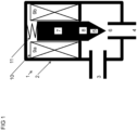
- FIG 1 shows the various components of a valve 1.
- the valve 1 advantageously is or comprises an expansion valve. Yet more advantageously the valve 1 is or comprises an electronic expansion valve.
- the valve 1 may be installed in a refrigeration-vapour circuit.
- the valve 1 in accordance with at least one embodiment is advantageously part of a refrigeration-vapour circuit.
- the valve 1 comprises a housing 2.
- the valve housing 2 has sides defining a first port 3 and a second port 4.
- the first port 3 comprises a first conduit.
- the second port 4 comprises a second conduit.
- the first port 3 is an inlet port and the second port 4 is an outlet port 4.
- the first port 3 is an outlet port and the second port 4 is an inlet port.
- the first port 3 and the second port 4 are in fluid communication with each other to afford flow of a fluid through the valve 1.
- the fluid comprises a refrigerant.
- the fluid may, by way of non-limiting example, be a R32, R401A, R404A, R406A, R407A, R407C, R408A, R409A, R410A, R438A, R500, or a R502 refrigerant.
- the fluid at the inlet port advantageously is a liquid.
- the fluid at the outlet port preferably is a two-phase fluid.
- a fluid path extends between the first port 3 and the second port 4.
- a valve member 5 is situated in the fluid path.
- the valve member 5 is moveable.
- the valve member 5 cooperates with a valve seat 6. The position of the valve member 5 thereby varies and limits a flow rate of the fluid through the valve 1.
- a valve body is or comprises the housing 2.
- the housing 2 comprises a metallic material such as steel, especially austenitic (stainless) steel and/or ferrite steel.
- the housing 2 comprises aluminum (alloy) or gunmetal or brass.
- the housing 2 comprises a polymeric material.
- the housing 2 is manufactured using an additive manufacturing technique such as three-dimensional printing. Manufacture of the housing 2 can, in a specific embodiment, involve selective laser sintering. It is still envisaged that the housing 2 comprises a grey cast material and/or of nodular cast iron.
- a fluid conduit in between the first port 3 and the second port 4 is or comprises a polymeric member. It is also envisaged that manufacture of the fluid conduit and/or of the first port 3 and/or of the second port 4 involves additive manufacturing such as three-dimensional printing. Manufacture of the fluid conduit and/or of the first port 3 and/or of the second port 4 can involve selective laser sintering.
- FIG 1 shows the valve seat 6 as part of the second port 4.
- the first port 3 can also comprise the valve seat 6.
- the valve seat 6 is separate from the first port 3.
- the valve seat 6 can also be separate from the second port 4.
- valve member 5 is linearly moveable by linear movement of the armature 7.
- the armature 7 can mechanically connect to the valve member 5 via a stem 8. It is also envisaged that the armature 7 directly connects to the valve member 5.
- the armature 7, the stem 8, and the valve member 5 form a single piece. That is, the stem 8 and the valve member 5 are both integral parts of the armature 7. Likewise, the armature 7 and the stem 8 are integral with the valve member 5.
- the valve member 5 is configured to rotate to some extent with respect to the armature 7.
- the valve member 5 preferably rotates about an axis connecting the armature 7, the valve member 5, and/or the stem 8.
- the valve member 5 is allowed to rotate by an articulation angle of 0.1 degrees or of 0.2 degrees or even of 0.5 degrees. A limited amount of articulation of the valve member 5 with respect to the armature 7 alleviates mechanical constraints.
- At least a portion of the armature 7 can be surrounded by a coil 9a, 9b.
- the coil 9a, 9b Upon application of an electric current, the coil 9a, 9b produces a magnetic flux. This magnetic flux acts on the armature 7 thereby displacing the armature 7.
- the coil 9a, 9b preferably comprises a solenoid 9a, 9b and/or a solenoid coil 9a, 9b.
- the coil 9a, 9b ideally is a solenoid 9a, 9b and/or a solenoid coil 9a, 9b.
- the armature 7 has an outer surface. In an embodiment, a portion of the outer surface of the armature 7 directly faces the coil 9a, 9b. In another embodiment, the outer surface of the armature 7 directly faces the coil 9a, 9b. Likewise, the coil 9a, 9b has an outer surface. In an embodiment, a portion of the outer surface of the coil 9a, 9b directly faces the armature 7. In another embodiment, the outer surface of the coil 9a, 9b directly faces the armature 7.
- the coil 9a, 9b and the armature 7 can be arranged in the same chamber 10 inside the housing 2.
- the chamber 10 is ideally filled with a liquid fluid.
- the liquid fluid inside the chamber 10 can be a R401A, R404A, R406A, R407A, R407C, R408A, R409A, R410A, R438A, -500, or a R502 refrigerant.
- a resilient member 11 ensures that the valve 1 is a normally closed valve.
- the resilient member 11 couples to the armature 7.
- the resilient member 11 mechanically connects to the armature 7.
- the resilient member 11 urges the armature 7 and the valve member 5 to close the valve 1. To that end, the resilient member 11 urges the armature 7 and the valve member 5 toward the seat 6. In a specific embodiment, the resilient member 11 urges the armature 7, the stem 8, and the valve member 5 to close the valve 1. To that end, the resilient member 11 urges the armature 7, the stem 8, and the valve member 5 toward the seat 6. The member 11 preferably urges these movable members 7a, 8, 5a toward the seat 6 until the valve member 5 engages the seat 6. The valve member 5 advantageously engages the seat 6 at a closed position.
- the resilient member 11 comprises a compression spring.
- the resilient member 11 can also be a compression spring.
- the resilient member 11 comprises a helical compression spring.
- the resilient member 11 can also be a helical compression spring.
- a tension spring can be attached to the second port 4 and to the stem 8. The tension spring then urges the stem 8 toward the second port 4.
- FIG 1 illustrates a valve having a linear actuator.
- the present disclosure also applies to valves 1 having rotating actuators. More specifically, the instant disclosure also applies to valves 1 having actuators in the form of stepper motors.
- the coil 9a, 9b connects to a source of electric power 12.
- the source 12 provides an alternating electric current to the coil 9a, 9b.
- the alternating electric current can, by way of non-limiting example, be an alternating electric current at a frequency of 50 hertz or at a frequency of 60 hertz.
- the alternating electric current can, by way of another non-limiting example, the alternating electric current at a frequency of 400 hertz.
- the coil 9a, 9b comprises a solenoid 9a, 9b and/or a solenoid coil 9a, 9b. Consequently, the source 12 provides an alternating electric current to the solenoid 9a, 9b and/or to the solenoid coil 9a, 9b.
- the alternating electric current can, by way of non-limiting example, be an alternating electric current at a frequency of 50 hertz or at a frequency of 60 hertz.
- the alternating electric current can, by way of another non-limiting example, the alternating electric current at a frequency of 400 hertz.
- the coil 9a, 9b is a solenoid 9a, 9b and/or is a solenoid coil 9a, 9b. Consequently, the source 12 provides an alternating electric current to the solenoid 9a, 9b and/or to the solenoid coil 9a, 9b.
- the alternating electric current can, by way of non-limiting example, be an alternating electric current at a frequency of 50 hertz or at a frequency of 60 hertz.
- the alternating electric current can, by way of another non-limiting example, the alternating electric current at a frequency of 400 hertz.
- the source 12 provides a direct electric current to the coil 9a, 9b.
- the direct electric current can, by way of non-limiting example, be applied at a voltage between 0 Volt and 3.3 Volts or between 0 Volt and 5 Volts.
- the direct electric current can, by way of another non-limiting example, be applied at a voltage between 0 Volt and 12 Volts or between 0 Volt and 24 Volts.
- the coil 9a, 9b comprises a solenoid 9a, 9b and/or a solenoid coil 9a, 9b. Consequently, the source 12 provides a direct electric current to the solenoid 9a, 9b and/or to the solenoid coil 9a, 9b.
- the direct electric current can, by way of non-limiting example, be applied at a voltage between 0 Volt and 3.3 Volts or between 0 Volt and 5 Volts.
- the direct electric current can, by way of another non-limiting example, be applied at a voltage between 0 Volt and 12 Volts or between 0 Volt and 24 Volts.
- the coil 9a, 9b is a solenoid 9a, 9b and/or is a solenoid coil 9a, 9b. Consequently, the source 12 provides a direct electric current to the solenoid 9a, 9b and/or to the solenoid coil 9a, 9b.
- the direct electric current can, by way of non-limiting example, be applied at a voltage between 0 Volt and 3.3 Volts or between 0 Volt and 5 Volts.
- the direct electric current can, by way of another non-limiting example, be applied at a voltage between 0 Volt and 12 Volts or between 0 Volt and 24 Volts.
- the source 12 provides a pulse-width modulated signal to the coil 9a, 9b.
- the pulse-width modulated signal can be a pulse-width modulated electric current or a pulse-width modulated electric voltage.
- a pulse-width modulated electric current can be applied using a duty cycle such as ten percent or twenty percent or fifty percent.
- a pulse-width modulated electric voltage can also be applied using a duty cycle such as ten percent or twenty percent or fifty percent.
- the coil 9a, 9b comprises a solenoid 9a, 9b and/or a solenoid coil 9a, 9b. Consequently, the source 12 provides a pulse-width modulated signal to the solenoid 9a, 9b and/or to the solenoid coil 9a, 9b.
- the pulse-width modulated signal can be a pulse-width modulated electric current or a pulse-width modulated electric voltage.
- a pulse-width modulated electric current can be applied using a duty cycle such as ten percent or twenty percent or fifty percent.
- a pulse-width modulated electric voltage can also be applied using a duty cycle such as ten percent or twenty percent or fifty percent.
- the coil 9a, 9b is a solenoid 9a, 9b and/or is a solenoid coil 9a, 9b. Consequently, the source 12 provides a pulse-width modulated signal to the solenoid 9a, 9b and/or to the solenoid coil 9a, 9b.
- the pulse-width modulated signal can be a pulse-width modulated electric current or a pulse-width modulated electric voltage.
- a pulse-width modulated electric current can be applied using a duty cycle such as ten percent or twenty percent or fifty percent.
- a pulse-width modulated electric voltage can also be applied using a duty cycle such as ten percent or twenty percent or fifty percent.
- the coil 9a, 9b is a solenoid 9a, 9b and/or is a solenoid coil 9a, 9b. Consequently, the source 12 provides a pulse-width modulated signal to the solenoid 9a, 9b and/or to the solenoid coil 9a, 9b.
- the frequency of the pulse-width modulated signal can, by way of non-limiting example, exceed one kilohertz.
- the frequency of the pulse-width modulated signal can, by way of another non-limiting example, exceed one megahertz.
- the source 12 applies an electric current to the coil 9a, 9b.
- the electric current as applied by the source 12 will flow between the terminals of the coil 9a, 9b.
- the electric current can be known because the source 12 is controlled such that it applies a given amount of electric current.
- the electric current through the coil 9a, 9b can also be recorded via a first meter 13.
- the first meter 13 preferably comprises a current meter such as an Ampere meter.
- the first meter 13 ideally is a current meter such as an Ampere meter.
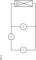
- the first meter 13 is electrically connected in series with the source 12 and with the coil 9a, 9b.
- the coil 9a, 9b comprises a solenoid 9a, 9b and/or a solenoid coil 9a, 9b.
- the electric current can be known because the source 12 is controlled such that it applies a given amount of electric current.
- the electric current through the solenoid 9a, 9b and/or through the solenoid coil 9a, 9b can also be recorded via a first meter 13.
- the first meter 13 preferably comprises a current meter such as an Ampere meter.
- the first meter 13 ideally is a current meter such as an Ampere meter.
- the first meter 13 is electrically connected in series with the source 12 and with the coil 9a, 9b.
- the coil 9a, 9b is a solenoid 9a, 9b and/or is a solenoid coil 9a, 9b.
- the electric current can be known because the source 12 is controlled such that it applies a given amount of electric current.
- the electric current through the solenoid 9a, 9b and/or through the solenoid coil 9a, 9b can also be recorded via a first meter 13.
- the first meter 13 preferably comprises a current meter such as an Ampere meter.
- the first meter 13 ideally is a current meter such as an Ampere meter.
- the first meter 13 is electrically connected in series with the source 12 and with the coil 9a, 9b.
- the source 12 also applies an electric voltage to the coil 9a, 9b.
- the electric voltage as applied by the source 12 will be applied between the terminals of the coil 9a, 9b.
- the electric voltage can be known because the source 12 is controlled such that it applies a given electric voltage.
- the electric voltage applied between the terminals of the coil 9a, 9b can also be recorded via a second meter 14.
- the second meter 14 is advantageously different from the first meter 13.
- the second meter 14 preferably comprises a voltage meter.
- the second meter 14 ideally is a voltage meter.
- the second meter 14 is electrically connected in parallel with the source 12 and in parallel with the coil 9a, 9b.
- the coil 9a, 9b comprises a solenoid 9a, 9b and/or a solenoid coil 9a, 9b.
- the electric voltage between the terminals of the solenoid 9a, 9b and/or the solenoid coil 9a, 9b can be known because the source 12 is controlled.
- the source 12 is then controlled such that it applies a given electric voltage.
- the electric voltage applied between the terminals of the solenoid 9a, 9b and/or of the solenoid coil 9a, 9b can also be recorded via a second meter 14.
- the second meter 14 preferably comprises a voltage meter.
- the second meter 14 ideally is a voltage meter.
- the second meter 14 is electrically connected in parallel with the source 12 and in parallel with the coil 9a, 9b.
- the coil 9a, 9b is a solenoid 9a, 9b and/or is a solenoid coil 9a, 9b.
- the electric voltage between the terminals of the solenoid 9a, 9b and/or the solenoid coil 9a, 9b can be known because the source 12 is controlled. The source 12 is then controlled such that it applies a given electric voltage.
- the electric voltage applied between the terminals of the solenoid 9a, 9b and/or of the solenoid coil 9a, 9b can also be recorded via a second meter 14.
- the second meter 14 preferably comprises a voltage meter.
- the second meter 14 ideally is a voltage meter.
- the second meter 14 is electrically connected in parallel with the source 12 and in parallel with the coil 9a, 9b.
- FIG 3 shows a controller 15.
- the controller 15 functions to relate the electric current through the coil 9a, 9b and the electric voltage applied to the coil 9a, 9b. That way, an electric resistance of the coil 9a, 9b can be estimated. Preferably, an electric resistance of the coil 9a, 9b can be determined. Ideally, an electric resistance of the coil 9a, 9b can be calculated.
- the coil 9a, 9b comprises a solenoid 9a, 9b and/or a solenoid coil 9a, 9b.
- the controller 15 then functions to relate at least one first electric signal and at least one second electric signal.
- the at least one first electric signal is the electric current through the solenoid 9a, 9b and/or through the solenoid coil 9a, 9b.
- the at least one second electric signal is the electric voltage applied to the solenoid 9a, 9b and/or to the solenoid coil 9a, 9b. That way, an electric resistance of the solenoid 9a, 9b and/or of the solenoid coil 9a, 9b can be estimated.
- an electric resistance of the solenoid 9a, 9b and/or of the solenoid coil 9a, 9b can be determined.
- an electric resistance of the solenoid 9a, 9b and/or of the solenoid coil 9a, 9b can be calculated.
- the coil 9a, 9b is a solenoid 9a, 9b and/or is a solenoid coil 9a, 9b.
- the controller 15 then functions to relate at least one third electric signal and at least one fourth electric signal.
- the at least one third electric signal is the electric current through the solenoid 9a, 9b and/or through the solenoid coil 9a, 9b.
- the at least one fourth electric signal is the electric voltage applied to the solenoid 9a, 9b and/or to the solenoid coil 9a, 9b. That way, an electric resistance of the solenoid 9a, 9b and/or of the solenoid coil 9a, 9b can be estimated.
- an electric resistance of the solenoid 9a, 9b and/or of the solenoid coil 9a, 9b can be determined.
- an electric resistance of the solenoid 9a, 9b and/or of the solenoid coil 9a, 9b can be calculated.
- the controller 15 advantageously comprises a microcontroller and/or a microprocessor.
- the controller 15 is a microcontroller and/or is a microprocessor.
- the controller 15 preferably comprises a memory such as a non-volatile memory.
- FIG 3 shows a connection between the controller 15 and the source 12.
- the connection between the controller 15 and the source 12 can be bidirectional.
- a bidirectional connection affords flexibility.
- the source 12 can be controlled via by the controller 15 using closed-loop control.
- the source 12 can then send feedback signals to the controller 15.
- the connection between the controller 15 and the source 12 can also be unidirectional. Communication from the controller 15 to the source 12 is afforded by such a unidirectional connection.
- a unidirectional connection reduces complexity.
- the controller 15 controls the source 12 and the source 12 applies an electric current through the coil 9a, 9b.
- the electric current through the coil 9a, 9b is defined by an output signal of the controller 15.
- the controller 15 also controls the source 12 and the source applies an electric voltage between the terminals of the coil 9a, 9b.
- the electric voltage between the terminals of the coil 9a, 9b is also defined by an output signal of the controller 15.
- the meters 13, 14 are optional.
- the coil 9a, 9b comprises a solenoid 9a, 9b and/or a solenoid coil 9a, 9b.
- the controller 15 controls the source 12 and the source 12 applies an electric current through the solenoid 9a, 9b and/or through the solenoid coil 9a, 9b.
- the electric current through the solenoid 9a, 9b and/or through the solenoid coil 9a, 9b is defined by an output signal of the controller 15.
- the controlled source 12 also applies an electric voltage between the terminals of the solenoid 9a, 9b and/or of the solenoid coil 9a, 9b.
- the electric voltage between the terminals of the solenoid 9a, 9b and/or of the solenoid coil 9a, 9b is defined by an output of the controller 15.
- the meters 13, 14 are optional.
- the coil 9a, 9b is a solenoid 9a, 9b and/or is a solenoid coil 9a, 9b.
- the controller 15 controls the source 12 and the source 12 applies an electric current through the solenoid 9a, 9b and/or through the solenoid coil 9a, 9b.
- the electric current through the solenoid 9a, 9b and/or through the solenoid coil 9a, 9b is defined by an output signal of the controller 15.
- the controlled source 12 also applies an electric voltage between the terminals of the solenoid 9a, 9b and/or of the solenoid coil 9a, 9b.
- the electric voltage between the terminals of the solenoid 9a, 9b and/or of the solenoid coil 9a, 9b is defined by an output of the controller 15.
- the meters 13, 14 are optional.
- the electric currents and/or electric voltages are not known by virtue of a controlled source 12.
- Meters 13, 14 can then be necessary to obtain readings of electric current and/or of electric voltage.
- FIG 3 shows a connection between the controller 15 and the first meter 13.
- the connection between the controller 15 and the first meter 13 can be bidirectional. A bidirectional connection affords flexibility.
- the connection between the controller 15 and the first meter 13 can also be unidirectional. Communication from the first meter 13 to the controller 15 is facilitated by such a unidirectional connection.
- a unidirectional connection reduces complexity.
- the controller 15 comprises a first analog-to-digital converter.
- the first analog-to-digital converter provides conversion of analog signals from the first meter 13 into (digital) measures.
- the first analog-to-digital converter can be an integral part of the controller 15. That is, the first analog-to-digital converter and the controller 15 are arranged on the same system-on-a-chip.
- FIG 3 also shows a connection between the controller 15 and the second meter 14.
- the connection between the controller 15 and the second meter 14 can be bidirectional. A bidirectional connection affords flexibility.
- the connection between the controller 15 and the second meter 14 can also be unidirectional. Communication from the second meter 14 to the controller 15 is facilitated by such a unidirectional connection. A unidirectional connection reduces complexity.
- the controller 15 comprises a second analog-to-digital converter.
- the second analog-to-digital converter provides conversion of analog signals from the second meter 14 into (digital) measures.
- the second analog-to-digital converter can be an integral part of the controller 15. That is, the second analog-to-digital converter and the controller 15 are arranged on the same system-on-a-chip.
- the first analog-to-digital converter and the second analog-to-digital converter are the same.
- the solution becomes more compact. Also, the solution avoids extra analog-to-digital converters that are prone to failure.
- the first analog-to-digital converter is different from the second analog-to-digital converter.
- the controller 15 advantageously comprises at least one arithmetic logic unit (ALU).
- the controller 15 uses the one or more arithmetic logic units to perform computations.
- the controller 15 can, by way of non-limiting example, use the one or more arithmetic logic units to relate a first quantity to a second quantity.
- the first quantity is a voltage applied between the terminals of the coil 9a, 9b.
- that quantity is a voltage between the terminals of the solenoid 9a, 9b or between the terminals of the solenoid coil 9a, 9b.
- the second quantity is an electric current through the coil 9a, 9b.
- the second quantity is an electric current through the solenoid 9a, 9b or through the solenoid coil 9a, 9b.
- the controller 15 can, by way of another non-limiting example, use the one or more arithmetic logic units to divide a first quantity by a second quantity.
- the first quantity is a voltage applied between the terminals of the coil 9a, 9b.
- that quantity is a voltage between the terminals of the solenoid 9a, 9b or between the terminals of the solenoid coil 9a, 9b.
- the second quantity is an electric current through the coil 9a, 9b.
- the second quantity is an electric current through the solenoid 9a, 9b or through the solenoid coil 9a, 9b.
- the controller 15 obtains a first series of readings, each reading being indicative of an electric voltage applied between the terminals of the coil 9a, 9b.
- the first series of readings is obtained with the valve 1 in operation.
- the first series of readings can be obtained with the armature 7 of the valve 1 moving.
- the controller 15 also obtains a second series of readings, each reading being indicative of an electric current through the coil 9a, 9b.
- the second series of readings is obtained with the valve 1 in operation.
- the second series of readings can be obtained with the armature 7 of the valve 1 moving.
- every reading of the first series corresponds to a reading of the second series.
- individual readings of the first series and of the second series are obtained substantially at the same time.
- individual readings of the first series and of the second series are obtained at the same time.
- the coil 9a, 9b comprises a solenoid 9a, 9b and/or a solenoid coil 9a, 9b.
- the controller 15 obtains a first series of readings. Each reading is indicative of an electric voltage applied between the terminals of the solenoid 9a, 9b or of the solenoid coil 9a, 9b.
- the first series of readings is obtained with the valve 1 in operation.
- the first series of readings can be obtained with the armature 7 of the valve 1 moving.
- the controller 15 also obtains a second series of readings, each reading being indicative of an electric current through the solenoid 9a, 9b or through the solenoid coil 9a, 9b.
- the second series of readings is obtained with the valve 1 in operation.
- the second series of readings can be obtained with the armature 7 of the valve 1 moving.
- every reading of the first series corresponds to a reading of the second series.
- individual readings of the first series and of the second series are obtained substantially at the same time.
- individual readings of the first series and of the second series are obtained at the same time.
- the coil 9a, 9b is a solenoid 9a, 9b and/or is a solenoid coil 9a, 9b.
- the controller 15 obtains a first series of readings. Each reading is indicative of an electric voltage applied between the terminals of the solenoid 9a, 9b or of the solenoid coil 9a, 9b.
- the first series of readings is obtained with the valve 1 in operation.
- the first series of readings can be obtained with the armature 7 of the valve 1 moving.
- the controller 15 also obtains a second series of readings, each reading being indicative of an electric current through the solenoid 9a, 9b or through the solenoid coil 9a, 9b.
- the second series of readings is obtained with the valve 1 in operation.
- the second series of readings can be obtained with the armature 7 of the valve 1 moving.
- every reading of the first series corresponds to a reading of the second series.
- individual readings of the first series and of the second series are obtained substantially at the same time.
- individual readings of the first series and of the second series are obtained at the same time.
- the controller 15 then produces a third series from the first and second series. In so doing, the controller 15 relates the readings of the first series to the readings of the second series. More specifically, the controller 15 iterates the readings of the first series. Individual readings of the first series are related to individual readings of the second series. The controller 15 can also iterate the readings of the second series. Individual readings of the first series are related to individual readings of the second series.
- the third series preferably comprises values of electric impedance.
- An impedance value of the third series is obtained by relating a voltage reading of the first series to a current reading of the second series.
- the voltage reading of the first series advantageously corresponds to the current reading of the second series. That is, the reading of electric voltage and the reading of electric current have been recorded substantially at the same time. The reading of electric voltage and the reading of electric current can even have been recorded at the same time.
- the values of impedance obtained from the first and second series can fluctuate over time.
- a filter can be applied.
- the filter can, by way of example, be a moving average filter such as a simple moving average filter.
- the controller 15 can, by way of non-limiting example, comprise an application-specific integrated circuit for calculating moving averages.
- the controller 15 can, by way of another non-limiting example, comprise an application-specific integrated circuit for calculating simple moving averages.
- Application-specific integrated circuits afford effective and power-saving calculations of moving averages and of simple moving averages.
- the filter can, by way of another example, also be a low-pass filter such as a first order low-pass filter.
- the filter can have a time constant. Time constants of at least fifteen seconds or of at least thirty seconds or of at least fifty seconds afford effective mitigation of fluctuations.
- the filtered values y m can form a fourth series. Corrective action can be taken based on the filtered values y m .
- a coil 9a, 9b can be de-energised in the event of excessive filtered values s m . That is, the coil 9a, 9b will be de-energised if any of the filtered values y m exceeds a threshold v.
- the threshold v can be a predetermined threshold.
- a solenoid 9a, 9b or a solenoid coil 9a, 9b can be de-energised in the event of excessive filtered values y m . That is, the solenoid 9a, 9b or the solenoid coil 9a, 9b will be de-energised if any of the filtered values y m exceeds a threshold v.
- the threshold v can be a predetermined threshold.
- the third series ideally comprises values of electric resistance.
- a resistance value of the third series is obtained by relating a voltage reading of the first series to a current reading of the second series.
- the voltage reading of the first series advantageously corresponds to the current reading of the second series. That is, the reading of electric voltage and the reading of electric current have been recorded substantially at the same time. The reading of electric voltage and the reading of electric current can even have been recorded at the same time.
- the controller 15 can also divide readings of the first series by readings of the second series.
- the controller 15 can, by way of non-limiting example, use the one or more arithmetic logic units of the controller 15 to perform the division. More specifically, the controller 15 iterates the readings of the first series. Individual readings of the first series are divided by individual readings of the second series. The controller 15 can also iterate the readings of the second series. Individual readings of the first series are divided by individual readings of the second series.
- the third series advantageously comprises values of electric impedance.
- An impedance value of the third series is obtained by dividing a voltage reading of the first series by a current reading of the second series.
- the voltage reading of the first series advantageously corresponds to the current reading of the second series. That is, the reading of electric voltage and the reading of electric current have been recorded substantially at the same time. The reading of electric voltage and the reading of electric current can even have been recorded at the same time.
- the controller 15 can, by way of non-limiting example, use the one or more arithmetic logic units of the controller 15 to perform these divisions.
- the third series ideally comprises values of electric resistance.
- a resistance value of the third series is obtained by dividing a voltage reading of the first series by a current reading of the second series.
- the voltage reading of the first series advantageously corresponds to the current reading of the second series. That is, the reading of electric voltage and the reading of electric current have been recorded substantially at the same time. The reading of electric voltage and the reading of electric current can even have been recorded at the same time.
- the controller 15 can, by way of non-limiting example, use the one or more arithmetic logic units of the controller 15 to perform these divisions.
- the values of resistance obtained from the first and second series can fluctuate over time.
- the filter can, by way of example, be a moving average filter such as a simple moving average filter.
- the controller 15 can, by way of non-limiting example, comprise an application-specific integrated circuit for calculating moving averages.
- the controller 15 can, by way of another non-limiting example, comprise an application-specific integrated circuit for calculating simple moving averages.
- Application-specific integrated circuits afford effective and power-saving calculations of moving averages and of simple moving averages.
- the filter can, by way of another example, also be a low-pass filter such as a first order low-pass filter.
- the filter can have a time constant. Time constants of at least fifteen seconds or of at least thirty seconds or of at least fifty seconds afford effective mitigation of fluctuations.
- the filtered values s m can form a fourth series. Corrective action can be taken based on the filtered values s m .
- a coil 9a, 9b can be de-energised in the event of excessive filtered values s m . That is, the coil 9a, 9b will be de-energised if any of the filtered values s m exceeds a threshold t.
- the threshold t can be a predetermined threshold.
- a solenoid 9a, 9b or a solenoid coil 9a, 9b can be de-energised in the event of excessive filtered values s m . That is, the solenoid 9a, 9b or the solenoid coil 9a, 9b will be de-energised if any of the filtered values s m exceeds a threshold t.
- the threshold t can be a predetermined threshold.
- the present disclosure deals with a method of estimating an impedance of a winding (9a, 9b) inside an actuator (7, 8, 9a, 9b) of a valve (1), the method comprising the steps of:
- the method of estimating an impedance of a winding (9a, 9b) inside an actuator (7, 8, 9a, 9b) of a valve (1) advantageously is a method of determining an impedance of a winding (9a, 9b) inside an actuator (7, 8, 9a, 9b) of a valve (1). Accordingly, the method comprises the step of determining an impedance of the winding (9a, 9b) inside the actuator (7, 8, 9a, 9b) of the valve (1) by applying a filter to the first, second, and third impedance values.
- the method of estimating an impedance of a winding (9a, 9b) inside an actuator (7, 8, 9a, 9b) of a valve (1) ideally is a method of calculating an impedance of a winding (9a, 9b) inside an actuator (7, 8, 9a, 9b) of a valve (1). Accordingly, the method comprises the step of calculating an impedance of the winding (9a, 9b) inside the actuator (7, 8, 9a, 9b) of the valve (1) by applying a filter to the first, second, and third impedance values.
- the first, second, and third impedance values are real values. That is, the first impedance value is a first resistance value.
- the second impedance value is a second resistance value.
- the third impedance value is a third resistance value.
- the impedance of the winding (9a, 9b) inside the actuator (7, 8, 9a, 9b) of the valve (1) is real. That is, the impedance of the winding (9a, 9b) inside the actuator (7, 8, 9a, 9b) of the valve (1) is a resistance of the winding (9a, 9b) inside the actuator (7, 8, 9a, 9b) of the valve (1).
- the method preferably comprises the steps of:
- the first position is preferably different from the second position. It is envisaged that the first position is a first position of the actuator (7, 8, 9a, 9b) of the valve (1). It is also envisaged that the second position is a second position of the actuator (7, 8, 9a, 9b) of the valve (1). The first position of the actuator (7, 8, 9a, 9b) of the valve (1) is preferably different from the second position of the actuator (7, 8, 9a, 9b) of the valve (1).
- the method ideally comprises the steps of:
- the instant disclosure also deals with any of the aforementioned methods, the method comprising the step of: after sending the first position signal and while the actuator (7, 8, 9a, 9b) is moving to the first position, obtaining the second readings of electric current through and of electric voltage applied to the actuator (7, 8, 9a, 9b) of the valve (1).
- the present disclosure still deals with any of the aforementioned methods, the method comprising the step of: after sending the first position signal and while the actuator (7, 8, 9a, 9b) is moving to the first position, obtaining the second readings of electric current through and of electric voltage applied to the winding (9a, 9b) inside the actuator (7, 8, 9a, 9b) of the valve (1).
- the instant disclosure also deals with any of the aforementioned methods, the method comprising the step of: after sending the second position signal and while the actuator (7, 8, 9a, 9b) is moving to the second position, obtaining the third readings of electric current through and of electric voltage applied to the actuator (7, 8, 9a, 9b) of the valve (1).
- the present disclosure still deals with any of the aforementioned methods, the method comprising the step of: after sending the second position signal and while the actuator (7, 8, 9a, 9b) is moving to the second position, obtaining the third readings of electric current through and of electric voltage applied to the winding (9a, 9b) inside the actuator (7, 8, 9a, 9b) of the valve (1).
- the instant disclosure further deals with any of the aforementioned methods, the method comprising the steps of:
- the instant disclosure also deals with any of the aforementioned methods, the method comprising the step of: estimating the impedance of the winding (9a, 9b) inside the actuator (7, 8, 9a, 9b) of the valve (1) by applying a low-pass filter to the first, second, and third impedance values.
- the instant disclosure still deals with any of the aforementioned methods, the method comprising the step of: estimating the impedance of the winding (9a, 9b) inside the actuator (7, 8, 9a, 9b) of the valve (1) by applying a first-order low-pass filter to the first, second, and third impedance values.
- the present disclosure also deals with any of the aforementioned methods, the method comprising the step of: determining the impedance of the winding (9a, 9b) inside the actuator (7, 8, 9a, 9b) of the valve (1) by applying a low-pass filter to the first, second, and third impedance values.
- the instant disclosure still deals with any of the aforementioned methods, the method comprising the step of: calculating the impedance of the winding (9a, 9b) inside the actuator (7, 8, 9a, 9b) of the valve (1) by applying a low-pass filter to the first, second, and third impedance values.
- the present disclosure further deals with any of the aforementioned methods, the method comprising the step of: determining the impedance of the winding (9a, 9b) inside the actuator (7, 8, 9a, 9b) of the valve (1) by applying a first-order low-pass filter to the first, second, and third impedance values.
- the instant disclosure still further deals with any of the aforementioned methods, the method comprising the step of: calculating the impedance of the winding (9a, 9b) inside the actuator (7, 8, 9a, 9b) of the valve (1) by applying a first-order low-pass filter to the first, second, and third impedance values.
- the present disclosure also deals with any of the aforementioned methods not explicitly involving a low-pass filter, the method comprising the step of: estimating the impedance of the winding (9a, 9b) inside the actuator (7, 8, 9a, 9b) of the valve (1) by applying a moving average filter to the first, second, and third impedance values.
- the instant disclosure still deals with any of the aforementioned methods not explicitly involving a low-pass filter, the method comprising the step of: estimating the impedance of the winding (9a, 9b) inside the actuator (7, 8, 9a, 9b) of the valve (1) by applying a simple moving average filter to the first, second, and third impedance values.
- the present disclosure also deals with any of the aforementioned methods not explicitly involving a low-pass filter, the method comprising the step of: determining the impedance of the winding (9a, 9b) inside the actuator (7, 8, 9a, 9b) of the valve (1) by applying a moving average filter to the first, second, and third impedance values.
- the instant disclosure still deals with any of the aforementioned methods not explicitly involving a low-pass filter, the method comprising the step of: calculating the impedance of the winding (9a, 9b) inside the actuator (7, 8, 9a, 9b) of the valve (1) by applying a moving average filter to the first, second, and third impedance values.
- the present disclosure further deals with any of the aforementioned methods not explicitly involving a low-pass filter, the method comprising the step of: determining the impedance of the winding (9a, 9b) inside the actuator (7, 8, 9a, 9b) of the valve (1) by applying a simple moving average filter to the first, second, and third impedance values.
- the instant disclosure still further deals with any of the aforementioned methods not explicitly involving a low-pass filter, the method comprising the step of: calculating the impedance of the winding (9a, 9b) inside the actuator (7, 8, 9a, 9b) of the valve (1) by applying a simple moving average filter to the first, second, and third impedance values.
- the present disclosure also deals with any of the aforementioned methods, the method comprising the steps of:
- the present disclosure still further deals with any of the aforementioned methods, the method comprising the step of: determining a temperature of the winding (9a, 9b) inside the actuator (7, 8, 9a, 9b) of the valve (1) as a function of the impedance of the winding (9a, 9b) inside the actuator (7, 8, 9a, 9b) of the valve (1).
- the instant disclosure yet further deals with any of the aforementioned methods, the method comprising the step of: calculating a temperature of the winding (9a, 9b) inside the actuator (7, 8, 9a, 9b) of the valve (1) as a function of the impedance of the winding (9a, 9b) inside the actuator (7, 8, 9a, 9b) of the valve (1).
- the present disclosure still further deals with any of the aforementioned methods, the method comprising the step of: determining a temperature of the winding (9a, 9b) inside the actuator (7, 8, 9a, 9b) of the valve (1) as a function of the impedance of the winding (9a, 9b) inside the actuator (7, 8, 9a, 9b) of the valve (1).
- the instant disclosure also deals with any of the aforementioned methods involving a temperature of the winding (9a, 9b) inside the actuator (7, 8, 9a, 9b) of the valve (1), the method comprising the steps of:
- the present disclosure further deals with any of the aforementioned methods involving a temperature of the winding (9a, 9b) inside the actuator (7, 8, 9a, 9b) of the valve (1), the method comprising the steps of:
- the present disclosure also deals with any of the aforementioned methods, the method comprising the steps of:
- the instant disclosure further deals with any of the aforementioned methods, the method comprising the steps of:
- the present disclosure still deals with a valve (1) comprising an actuator (7, 8, 9a, 9b) having a winding (9a, 9b), a valve member (5) mechanically coupled to the actuator (7, 8, 9a, 9b), a controller (15) in operative communication with the actuator (7, 8, 9a, 9b), wherein the controller (15) is configured to:
- the controller (15) is preferably configured to determine an impedance of the winding (9a, 9b) of the actuator (7, 8, 9a, 9b) of the valve (1) by applying a filter to the first, second, and third impedance values.
- the controller (15) is ideally configured to calculate an impedance of the winding (9a, 9b) of the actuator (7, 8, 9a, 9b) of the valve (1) by applying a filter to the first, second, and third impedance values.
- the first, second, and third impedance values are real values. That is, the first impedance value is a first resistance value.
- the second impedance value is a second resistance value.
- the third impedance value is a third resistance value.
- the impedance of the winding (9a, 9b) of the actuator (7, 8, 9a, 9b) of the valve (1) is real. That is, the impedance of the winding (9a, 9b) of the actuator (7, 8, 9a, 9b) of the valve (1) is a resistance of the winding (9a, 9b) of the actuator (7, 8, 9a, 9b) of the valve (1).
- the first position is preferably different from the second position. It is envisaged that the first position is a first position of the actuator (7, 8, 9a, 9b) of the valve (1). It is also envisaged that the second position is a second position of the actuator (7, 8, 9a, 9b) of the valve (1).
- the first position is advantageously associated also with a first position of the valve member (5).
- the second position is advantageously associated also with a second position of the valve member (5).
- the first position of the actuator (7, 8, 9a, 9b) of the valve (1) is preferably different from the second position of the actuator (7, 8, 9a, 9b) of the valve (1).
- controller (15) is configured to:
- controller (15) is configured to:
- valve (1) comprising a power source (12) electrically connected to the winding (9a, 9b) of the actuator (7, 8, 9a, 9b) and in operative communication with the controller (15), wherein the controller (15) is configured to:
- valve (1) comprises a current meter (13) electrically connected in series with the winding (9a, 9b) of the actuator (7, 8, 9a, 9b) of the valve (1) and a voltage meter (14) electrically connected in parallel with the winding (9a, 9b) of the actuator (7, 8, 9a, 9b) of the valve (1), the meters (13, 14) being in operative communication with the controller (15), wherein the controller (15) is configured to:
- the instant disclosure also deals with any of the aforementioned valves (1), wherein the controller (15) is configured to: after sending the first position signal and while the actuator (7, 8, 9a, 9b) is moving to the first position, obtain the second readings of electric current through and of electric voltage applied to the winding (9a, 9b) of the actuator (7, 8, 9a, 9b) of the valve (1).
- the present disclosure still deals with any of the aforementioned valves (1), wherein the controller (15) is configured to: after sending the second position signal and while the actuator (7, 8, 9a, 9b) is moving to the second position, obtain the third readings of electric current through and of electric voltage applied to the winding (9a, 9b) of the actuator (7, 8, 9a, 9b) of the valve (1).
- controller (15) is configured to:
- the present disclosure also deals with any of the aforementioned valves (1), wherein the controller (15) is configured to: estimate the impedance of the winding (9a, 9b) of the actuator (7, 8, 9a, 9b) of the valve (1) by applying a low-pass filter to the first, second, and third impedance values.
- the instant disclosure still deals with any of the aforementioned valves (1), wherein the controller (15) is configured to: estimate the impedance of the winding (9a, 9b) of the actuator (7, 8, 9a, 9b) of the valve (1) by applying a first-order low-pass filter to the first, second, and third impedance values.
- the present disclosure also deals with any of the aforementioned valves (1), wherein the controller (15) is configured to: determine the impedance of the winding (9a, 9b) of the actuator (7, 8, 9a, 9b) of the valve (1) by applying a low-pass filter to the first, second, and third impedance values.
- the instant disclosure still deals with any of the aforementioned valves (1), wherein the controller (15) is configured to: calculate the impedance of the winding (9a, 9b) of the actuator (7, 8, 9a, 9b) of the valve (1) by applying a low-pass filter to the first, second, and third impedance values.
- the present disclosure further deals with any of the aforementioned valves (1), wherein the controller (15) is configured to: determine the impedance of the winding (9a, 9b) of the actuator (7, 8, 9a, 9b) of the valve (1) by applying a first-order low-pass filter to the first, second, and third impedance values.
- controller (15) is configured to: calculate the impedance of the winding (9a, 9b) of the actuator (7, 8, 9a, 9b) of the valve (1) by applying a first-order low-pass filter to the first, second, and third impedance values.
- the present disclosure also deals with any of the aforementioned valves (1) not explicitly involving a low-pass filter, wherein the controller (15) is configured to: estimate the impedance of the winding (9a, 9b) of the actuator (7, 8, 9a, 9b) of the valve (1) by applying a moving average filter to the first, second, and third impedance values.
- the instant disclosure still deals with any of the aforementioned valves (1) not explicitly involving a low-pass filter, wherein the controller (15) is configured to: estimate the impedance of the winding (9a, 9b) of the actuator (7, 8, 9a, 9b) of the valve (1) by applying a simple moving average filter to the first, second, and third impedance values.
- the present disclosure also deals with any of the aforementioned valves (1) not explicitly involving a low-pass filter, wherein the controller (15) is configured to: determine the impedance of the winding (9a, 9b) of the actuator (7, 8, 9a, 9b) of the valve (1) by applying a moving average filter to the first, second, and third impedance values.
- the instant disclosure still deals with any of the aforementioned valves (1) not explicitly involving a low-pass filter, wherein the controller (15) is configured to: calculate the impedance of the winding (9a, 9b) of the actuator (7, 8, 9a, 9b) of the valve (1) by applying a moving average filter to the first, second, and third impedance values.
- the present disclosure further deals with any of the aforementioned valves (1) not explicitly involving a low-pass filter, wherein the controller (15) is configured to: determine the impedance of the winding (9a, 9b) of the actuator (7, 8, 9a, 9b) of the valve (1) by applying a simple moving average filter to the first, second, and third impedance values.
- the instant disclosure still further deals with any of the aforementioned valves (1) not explicitly involving a low-pass filter, wherein the controller (15) is configured to: calculate the impedance of the winding (9a, 9b) of the actuator (7, 8, 9a, 9b) of the valve (1) by applying a simple moving average filter to the first, second, and third impedance values.
- controller (15) comprises an application-specific integrated circuit for estimating moving averages and is configured to: use the application-specific integrated circuit to estimate the impedance of the winding (9a, 9b) of the actuator (7, 8, 9a, 9b) of the valve (1) by applying a moving average filter to the first, second, and third impedance values.
- the controller comprises an application-specific integrated circuit for estimating simple moving averages and is configured to: use the application-specific integrated circuit to estimate the impedance of the winding (9a, 9b) of the actuator (7, 8, 9a, 9b) of the valve (1) by applying a simple moving average filter to the first, second, and third impedance values.
- the present disclosure also deals with any of the aforementioned valves (1) not explicitly involving a low-pass filter, wherein the controller (15) comprises an application-specific integrated circuit for determining moving averages and is configured to: use the application-specific integrated circuit to determine the impedance of the winding (9a, 9b) of the actuator (7, 8, 9a, 9b) of the valve (1) by applying a moving average filter to the first, second, and third impedance values.
- the controller comprises an application-specific integrated circuit for determining moving averages and is configured to: use the application-specific integrated circuit to determine the impedance of the winding (9a, 9b) of the actuator (7, 8, 9a, 9b) of the valve (1) by applying a moving average filter to the first, second, and third impedance values.
- the controller comprises an application-specific integrated circuit for calculating moving averages and is configured to: use the application-specific integrated circuit to calculate the impedance of the winding (9a, 9b) of the actuator (7, 8, 9a, 9b) of the valve (1) by applying a moving average filter to the first, second, and third impedance values.
- the present disclosure further deals with any of the aforementioned valves (1) not explicitly involving a low-pass filter, wherein the controller (15) comprises an application-specific integrated circuit for determining simple moving averages and is configured to: use the application-specific integrated circuit to determine the impedance of the winding (9a, 9b) of the actuator (7, 8, 9a, 9b) of the valve (1) by applying a simple moving average filter to the first, second, and third impedance values.
- the controller comprises an application-specific integrated circuit for determining simple moving averages and is configured to: use the application-specific integrated circuit to determine the impedance of the winding (9a, 9b) of the actuator (7, 8, 9a, 9b) of the valve (1) by applying a simple moving average filter to the first, second, and third impedance values.
- the controller comprises an application-specific integrated circuit for calculating simple moving averages and is configured to: use the application-specific integrated circuit to calculate the impedance of the winding (9a, 9b) of the actuator (7, 8, 9a, 9b) of the valve (1) by applying a simple moving average filter to the first, second, and third impedance values.
- valve (1) comprises an electric switch electrically connected to the actuator (7, 8, 9a, 9b) and being in operative communication with the controller (15), wherein the controller (15) is configured to:
- valve (1) comprises an electric switch electrically connected to the actuator (7, 8, 9a, 9b) and being in operative communication with the controller (15), wherein the controller (15) is configured to:
- valve (1) comprises an electric switch electrically connected to the winding (9a, 9b) of the actuator (7, 8, 9a, 9b) and being in operative communication with the controller (15), wherein the controller (15) is configured to:
- valve (1) comprises an electric switch electrically connected to the winding (9a, 9b) of the actuator (7, 8, 9a, 9b) and being in operative communication with the controller (15), wherein the controller (15) is configured to:
- the present disclosure also deals with a computer program comprising instructions to cause the controller (15) of any of the aforementioned valves (1) to execute the steps of any of the aforementioned methods.
- the instant disclosure also deals with a computer program product comprising instructions to cause the controller (15) of any of the aforementioned valves (1) to execute the steps of any of the aforementioned methods.
- the present disclosure also deals with a computer-readable data carrier having stored thereon any of the aforementioned computer programs.
- the instant disclosure also deals with a computer-readable data carrier having stored thereon any of the aforementioned computer program products.
Landscapes
- Engineering & Computer Science (AREA)
- General Engineering & Computer Science (AREA)
- Mechanical Engineering (AREA)
- Power Engineering (AREA)
- Physics & Mathematics (AREA)
- General Physics & Mathematics (AREA)
- Electromagnets (AREA)
Abstract
Continuous impedance and/or resistance measurements. A method of estimating an impedance of a winding (9a, 9b) inside an actuator (7, 8, 9a, 9b) of a valve (1), the method comprising: obtaining first readings of electric current through and of electric voltage applied to the actuator (7, 8, 9a, 9b) of the valve (1); after obtaining the first readings, sending a first signal to the actuator (7, 8, 9a, 9b) of the valve (1), the first signal causing the actuator (7, 8, 9a, 9b) to move to a first position; after sending the first signal, obtaining second readings of electric current through and of electric voltage applied to the actuator (7, 8, 9a, 9b) of the valve (1); then sending a second signal to the actuator (7, 8, 9a, 9b) of the valve (1), the second signal causing the actuator (7, 8, 9a, 9b) to move to a second position.
Description
- The present disclosure relates to a continuous measurement of the electric impedance and/or resistance of a coil. More specifically, the electric impedance and/or resistance of a coil is determined while the coil is in operation. The coil can, by way of non-limiting example, be a coil of an actuator. It is also envisaged that the coil is a coil of an actuator of a valve.
- Temperature rise tests of large power transformers according to IEC 60076-2, second edition, of April 1993, are conducted to estimate a maximum temperature inside the power transformer. To that end, the power transformer is operated at rated current for some time. The power transformer typically operates until temperature increases at a rate of less than one Kelvin per hour. The power transformer may also operate until temperature no longer rises.
- When the rate of temperature rise is low enough or the temperature no longer rises, the power transformer is shut down. The leads for supplying the rated current to the power transformer are disconnected. A set of leads is connected to the power transformer to measure the electric resistance of the winding.
- The measurement of electric resistance must be carried out shortly after the shutdown. The measurement is carried out by applying a direct electric current to the winding. That is, the measurement of the electric resistance of the winding of the power transformer is conducted with the power transformer not being in operation. Eventually, a temperature inside the power transformer is estimated based on the electric resistance measured shortly or immediately after the shutdown.
- The practical difficulties of measuring the electric impedances and/or resistances of windings of actuators are exacerbated when the applied signal is not a direct current. The practical difficulties involved in such measurements of the electric impedances and/or resistances of windings of actuators can be further exacerbated when the applied voltage is non-sinusoidal. The applied voltage can, for example, be a pulse-width modulated signal. The shape of the applied signal over time then consists of rectangles or approximately consists of rectangles.
- Also, the inductance of the actuator can change during operation. The poles of the rotating parts of the actuator will move past the coil and the inductance of the winding will vary accordingly.
- Those issues are up to now resolved by application of a constant voltage to a coil of an actuator. For the duration of the measurement, the position of any moving part such as the position of a moveable anchor is kept constant. In other words, the actuator does not move.
- A measurement of an electric current starts. The actual determination of the electric impedance and/or of the electric resistance of the coil is delayed until all or most transient effects have settled. Once the transient effects have settled, a measurement of electric current yields an estimate of the electric impedance and/or of the electric resistance of the coil. The temperature of the coil can eventually be estimated based on the electric resistance of the coil of the actuator. That procedure is somewhat unsatisfactory in that it does not afford estimates of coil temperature with the actuator in operation.
- A Japanese patent application
JPH03147532A was filed by SONY CORP on 1 November 1989 JPH03147532A - The optical disc device of
JPH03147532A JPH03147532A - To that end, a test voltage is applied to the actuator by a test voltage generator. A changeover switch operates before the test voltage can be applied. A controller then calculates the resistance of the actuator coil as a function of the terminal voltage of the actuator and the driving current. Since the temperature characteristic of the coil of the actuator is known, the temperature of the coil can also be calculated. Once the temperature has been calculated, it is compared to a threshold indicative of a permissible temperature. If the temperature exceeds the threshold, the entire optical disc device is taken out of operation. The changeover switch of
JPH03147532A - It is desirable to obtain measurements of the electric impedances and/or of the electric resistances of coils of actuators with the actuators in operation. More specifically, it is desirable to obtain such measurements while applying operational voltages and without interruption of the normal operation of the actuator.
- The present disclosure deals with measurements of electric impedances and/or electric resistances of windings of actuators of valves. The measurements shall preferably be carried out with the valve in operation. The measurements shall ideally be carried out while the actuator of the valve is moving. The actuator of the valve can move a valve member inside the valve. The winding of the actuator of the valve can, by way of non-limiting example, be at least one of
- a coil,
- a solenoid,
- a solenoid coil.
- a coil,
- a solenoid,
- a solenoid coil.
- Accordingly, first readings are obtained indicative of a current through and of a voltage applied to an actuator of the valve. More specifically, first readings are obtained indicative of a current through and of a voltage applied to the winding of the actuator of the valve. When the first readings have been obtained, a first position signal is sent to the actuator. The first position signal causes the actuator to attain a first position. The first position signal can be a first actuation signal.
- After the first position signal, second readings are obtained. The second readings are indicative of a current through and of a voltage applied to the actuator of the valve. The second readings are different from the first readings. The second readings are preferably obtained with the actuator in operation. That is, the second readings are obtained with the actuator moving.
- A second position signal is then sent to the actuator. The second position signal causes the actuator to attain a second position. The second position signal can be a second actuation signal.
- After the second position signal, third readings are obtained. The third readings are indicative of a current through and of a voltage applied to the actuator of the valve. The third readings are different from the first readings. The third readings are also different from the second readings. The third readings are preferably obtained with the actuator in operation. That is, the third readings are obtained with the actuator moving.
- The first to third readings are used to produce first to third impedance values. The first to third readings can also be used to produce first to third resistance values. The impedance values are produced by relating the respective voltage readings to the respective current readings. More specifically, the impedance values are produced by dividing the respective voltage readings by the respective current readings. Likewise, resistance values can be produced by relating the respective voltage readings to the respective current readings. More specifically, resistance values can be produced by dividing the respective voltage readings by the respective current readings.
- The values obtained from the readings vary. To mitigate variations, a filter such as
- a moving average filter,
- a simple moving average filter,
- a low-pass filter,
- a first-order low-pass filter
- More specifically, the filter functions to eliminate inductive parts of the impedance signal. Eventually, a resistance signal is produced by filtering the impedance signal.
- According to an aspect of the present disclosure, the impedance of the winding and/or the resistance of the winding affords fault detection. If the impedance and/or the resistance is too large, the valve or parts of the valve will be de-energised. More specifically, the actuator and/or the winding of the actuator will be de-energised.
- Estimates and/or determinations and/or calculations of (simple) moving averages can consume lots of computing power. To handle (simple) moving averages on systems with limited computational resources, application-specific integrated circuits can be employed. Application-specific integrated circuits afford computations of (simple) moving averages without requiring the excessive computational resources needed by general-purpose microcontrollers.
- Various features will become apparent to those skilled in the art from the following detailed description of the disclosed non-limiting embodiments. The drawings that accompany the detailed description can be briefly described as follows:
-
FIG 1 is a schematic of a valve having a coil. -
FIG 2 shows a coil connected to a source of electric power. -
FIG 3 illustrates a controller in operative communication with a source and optionally with one or more meters. - The instant disclosure deals with impedances and/or with resistances of coils. The coil can, by way of example, be a coil and/or a solenoid of a valve.
FIG 1 shows the various components of a valve 1. The valve 1 advantageously is or comprises an expansion valve. Yet more advantageously the valve 1 is or comprises an electronic expansion valve. The valve 1 may be installed in a refrigeration-vapour circuit. The valve 1 in accordance with at least one embodiment is advantageously part of a refrigeration-vapour circuit. - The valve 1 comprises a housing 2. The valve housing 2 has sides defining a
first port 3 and asecond port 4. In an embodiment, thefirst port 3 comprises a first conduit. It is also envisaged that thesecond port 4 comprises a second conduit. According to an aspect of the instant disclosure, thefirst port 3 is an inlet port and thesecond port 4 is anoutlet port 4. According to another aspect of the instant disclosure, thefirst port 3 is an outlet port and thesecond port 4 is an inlet port. - The
first port 3 and thesecond port 4 are in fluid communication with each other to afford flow of a fluid through the valve 1. In a preferred embodiment, the fluid comprises a refrigerant. The fluid may, by way of non-limiting example, be a R32, R401A, R404A, R406A, R407A, R407C, R408A, R409A, R410A, R438A, R500, or a R502 refrigerant. The fluid at the inlet port advantageously is a liquid. The fluid at the outlet port preferably is a two-phase fluid. - A fluid path extends between the
first port 3 and thesecond port 4. Avalve member 5 is situated in the fluid path. Thevalve member 5 is moveable. Thevalve member 5 cooperates with avalve seat 6. The position of thevalve member 5 thereby varies and limits a flow rate of the fluid through the valve 1. - It is envisaged that a valve body is or comprises the housing 2. In an embodiment, the housing 2 comprises a metallic material such as steel, especially austenitic (stainless) steel and/or ferrite steel. In an alternate embodiment, the housing 2 comprises aluminum (alloy) or gunmetal or brass. In yet another alternate embodiment, the housing 2 comprises a polymeric material. According to an aspect, the housing 2 is manufactured using an additive manufacturing technique such as three-dimensional printing. Manufacture of the housing 2 can, in a specific embodiment, involve selective laser sintering. It is still envisaged that the housing 2 comprises a grey cast material and/or of nodular cast iron.
- According to an aspect of the present disclosure, a fluid conduit in between the
first port 3 and thesecond port 4 is or comprises a polymeric member. It is also envisaged that manufacture of the fluid conduit and/or of thefirst port 3 and/or of thesecond port 4 involves additive manufacturing such as three-dimensional printing. Manufacture of the fluid conduit and/or of thefirst port 3 and/or of thesecond port 4 can involve selective laser sintering. -
FIG 1 shows thevalve seat 6 as part of thesecond port 4. Thefirst port 3 can also comprise thevalve seat 6. In an alternate embodiment, thevalve seat 6 is separate from thefirst port 3. Thevalve seat 6 can also be separate from thesecond port 4. - In the embodiment shown in
FIG 1 , thevalve member 5 is linearly moveable by linear movement of thearmature 7. Thearmature 7 can mechanically connect to thevalve member 5 via astem 8. It is also envisaged that thearmature 7 directly connects to thevalve member 5. - According to an aspect of the present disclosure, the
armature 7, thestem 8, and thevalve member 5 form a single piece. That is, thestem 8 and thevalve member 5 are both integral parts of thearmature 7. Likewise, thearmature 7 and thestem 8 are integral with thevalve member 5. - According to another aspect of the present disclosure, the
valve member 5 is configured to rotate to some extent with respect to thearmature 7. Thevalve member 5 preferably rotates about an axis connecting thearmature 7, thevalve member 5, and/or thestem 8. In an embodiment, thevalve member 5 is allowed to rotate by an articulation angle of 0.1 degrees or of 0.2 degrees or even of 0.5 degrees. A limited amount of articulation of thevalve member 5 with respect to thearmature 7 alleviates mechanical constraints. - At least a portion of the
armature 7 can be surrounded by acoil coil armature 7 thereby displacing thearmature 7. - The
coil solenoid solenoid coil coil solenoid solenoid coil - A can needs not envelope the
armature 7 and/or thestem 8. That is, thearmature 7 has an outer surface. In an embodiment, a portion of the outer surface of thearmature 7 directly faces thecoil armature 7 directly faces thecoil coil coil armature 7. In another embodiment, the outer surface of thecoil armature 7. - The
coil armature 7 can be arranged in thesame chamber 10 inside the housing 2. Thechamber 10 is ideally filled with a liquid fluid. For example, the liquid fluid inside thechamber 10 can be a R401A, R404A, R406A, R407A, R407C, R408A, R409A, R410A, R438A, -500, or a R502 refrigerant. - A
resilient member 11 ensures that the valve 1 is a normally closed valve. Theresilient member 11 couples to thearmature 7. In a specific embodiment, theresilient member 11 mechanically connects to thearmature 7. - The
resilient member 11 urges thearmature 7 and thevalve member 5 to close the valve 1. To that end, theresilient member 11 urges thearmature 7 and thevalve member 5 toward theseat 6. In a specific embodiment, theresilient member 11 urges thearmature 7, thestem 8, and thevalve member 5 to close the valve 1. To that end, theresilient member 11 urges thearmature 7, thestem 8, and thevalve member 5 toward theseat 6. Themember 11 preferably urges thesemovable members 7a, 8, 5a toward theseat 6 until thevalve member 5 engages theseat 6. Thevalve member 5 advantageously engages theseat 6 at a closed position. - According to an aspect, the
resilient member 11 comprises a compression spring. Theresilient member 11 can also be a compression spring. In a special embodiment, theresilient member 11 comprises a helical compression spring. Theresilient member 11 can also be a helical compression spring. - The skilled person understands that a tension spring can be attached to the
second port 4 and to thestem 8. The tension spring then urges thestem 8 toward thesecond port 4. -
FIG 1 illustrates a valve having a linear actuator. The present disclosure also applies to valves 1 having rotating actuators. More specifically, the instant disclosure also applies to valves 1 having actuators in the form of stepper motors. - Now turning to
FIG 2 , thecoil electric power 12. In an embodiment, thesource 12 provides an alternating electric current to thecoil - It is envisaged that the
coil solenoid solenoid coil source 12 provides an alternating electric current to thesolenoid solenoid coil - It is still envisaged that the
coil solenoid solenoid coil source 12 provides an alternating electric current to thesolenoid solenoid coil - In another embodiment, the
source 12 provides a direct electric current to thecoil - It is envisaged that the
coil solenoid solenoid coil source 12 provides a direct electric current to thesolenoid solenoid coil - It is still envisaged that the
coil solenoid solenoid coil source 12 provides a direct electric current to thesolenoid solenoid coil - In yet another embodiment, the
source 12 provides a pulse-width modulated signal to thecoil - It is envisaged that the
coil solenoid solenoid coil source 12 provides a pulse-width modulated signal to thesolenoid solenoid coil - It is still envisaged that the
coil solenoid solenoid coil source 12 provides a pulse-width modulated signal to thesolenoid solenoid coil - It is also envisaged that the
coil solenoid solenoid coil source 12 provides a pulse-width modulated signal to thesolenoid solenoid coil - The
source 12 applies an electric current to thecoil source 12 will flow between the terminals of thecoil source 12 is controlled such that it applies a given amount of electric current. The electric current through thecoil first meter 13. Thefirst meter 13 preferably comprises a current meter such as an Ampere meter. Thefirst meter 13 ideally is a current meter such as an Ampere meter. Thefirst meter 13 is electrically connected in series with thesource 12 and with thecoil - It is envisaged that the
coil solenoid solenoid coil source 12 is controlled such that it applies a given amount of electric current. The electric current through thesolenoid solenoid coil first meter 13. Thefirst meter 13 preferably comprises a current meter such as an Ampere meter. Thefirst meter 13 ideally is a current meter such as an Ampere meter. Thefirst meter 13 is electrically connected in series with thesource 12 and with thecoil - It is still envisaged that the
coil solenoid solenoid coil source 12 is controlled such that it applies a given amount of electric current. The electric current through thesolenoid solenoid coil first meter 13. Thefirst meter 13 preferably comprises a current meter such as an Ampere meter. Thefirst meter 13 ideally is a current meter such as an Ampere meter. Thefirst meter 13 is electrically connected in series with thesource 12 and with thecoil - The
source 12 also applies an electric voltage to thecoil source 12 will be applied between the terminals of thecoil source 12 is controlled such that it applies a given electric voltage. The electric voltage applied between the terminals of thecoil second meter 14. Thesecond meter 14 is advantageously different from thefirst meter 13. Thesecond meter 14 preferably comprises a voltage meter. Thesecond meter 14 ideally is a voltage meter. Thesecond meter 14 is electrically connected in parallel with thesource 12 and in parallel with thecoil - It is envisaged that the
coil solenoid solenoid coil solenoid solenoid coil source 12 is controlled. Thesource 12 is then controlled such that it applies a given electric voltage. The electric voltage applied between the terminals of thesolenoid solenoid coil second meter 14. Thesecond meter 14 preferably comprises a voltage meter. Thesecond meter 14 ideally is a voltage meter. Thesecond meter 14 is electrically connected in parallel with thesource 12 and in parallel with thecoil - It is still envisaged that the
coil solenoid solenoid coil solenoid solenoid coil source 12 is controlled. Thesource 12 is then controlled such that it applies a given electric voltage. The electric voltage applied between the terminals of thesolenoid solenoid coil second meter 14. Thesecond meter 14 preferably comprises a voltage meter. Thesecond meter 14 ideally is a voltage meter. Thesecond meter 14 is electrically connected in parallel with thesource 12 and in parallel with thecoil -
FIG 3 shows acontroller 15. Thecontroller 15 functions to relate the electric current through thecoil coil coil coil coil - It is envisaged that the
coil solenoid solenoid coil controller 15 then functions to relate at least one first electric signal and at least one second electric signal. The at least one first electric signal is the electric current through thesolenoid solenoid coil solenoid solenoid coil solenoid solenoid coil solenoid solenoid coil solenoid solenoid coil - It is still envisaged that the
coil solenoid solenoid coil controller 15 then functions to relate at least one third electric signal and at least one fourth electric signal. The at least one third electric signal is the electric current through thesolenoid solenoid coil solenoid solenoid coil solenoid solenoid coil solenoid solenoid coil solenoid solenoid coil - The
controller 15 advantageously comprises a microcontroller and/or a microprocessor. In an embodiment, thecontroller 15 is a microcontroller and/or is a microprocessor. Thecontroller 15 preferably comprises a memory such as a non-volatile memory. -
FIG 3 shows a connection between thecontroller 15 and thesource 12. The connection between thecontroller 15 and thesource 12 can be bidirectional. A bidirectional connection affords flexibility. For example, thesource 12 can be controlled via by thecontroller 15 using closed-loop control. Thesource 12 can then send feedback signals to thecontroller 15. The connection between thecontroller 15 and thesource 12 can also be unidirectional. Communication from thecontroller 15 to thesource 12 is afforded by such a unidirectional connection. A unidirectional connection reduces complexity. - In an embodiment, the
controller 15 controls thesource 12 and thesource 12 applies an electric current through thecoil coil controller 15. Thecontroller 15 also controls thesource 12 and the source applies an electric voltage between the terminals of thecoil coil controller 15. In consequence of the controlled output currents and controlled output voltages, themeters - It is envisaged that the
coil solenoid solenoid coil controller 15 controls thesource 12 and thesource 12 applies an electric current through thesolenoid solenoid coil solenoid solenoid coil controller 15. The controlledsource 12 also applies an electric voltage between the terminals of thesolenoid solenoid coil solenoid solenoid coil controller 15. In consequence of the controlled output currents and controlled output voltages, themeters - It is still envisaged that the
coil solenoid solenoid coil controller 15 controls thesource 12 and thesource 12 applies an electric current through thesolenoid solenoid coil solenoid solenoid coil controller 15. The controlledsource 12 also applies an electric voltage between the terminals of thesolenoid solenoid coil solenoid solenoid coil controller 15. In consequence of the controlled output currents and controlled output voltages, themeters - In another embodiment, the electric currents and/or electric voltages are not known by virtue of a controlled
source 12.Meters -
FIG 3 shows a connection between thecontroller 15 and thefirst meter 13. The connection between thecontroller 15 and thefirst meter 13 can be bidirectional. A bidirectional connection affords flexibility. The connection between thecontroller 15 and thefirst meter 13 can also be unidirectional. Communication from thefirst meter 13 to thecontroller 15 is facilitated by such a unidirectional connection. A unidirectional connection reduces complexity. - In a compact embodiment, the
controller 15 comprises a first analog-to-digital converter. The first analog-to-digital converter provides conversion of analog signals from thefirst meter 13 into (digital) measures. The first analog-to-digital converter can be an integral part of thecontroller 15. That is, the first analog-to-digital converter and thecontroller 15 are arranged on the same system-on-a-chip. -
FIG 3 also shows a connection between thecontroller 15 and thesecond meter 14. The connection between thecontroller 15 and thesecond meter 14 can be bidirectional. A bidirectional connection affords flexibility. The connection between thecontroller 15 and thesecond meter 14 can also be unidirectional. Communication from thesecond meter 14 to thecontroller 15 is facilitated by such a unidirectional connection. A unidirectional connection reduces complexity. - In a compact embodiment, the
controller 15 comprises a second analog-to-digital converter. The second analog-to-digital converter provides conversion of analog signals from thesecond meter 14 into (digital) measures. The second analog-to-digital converter can be an integral part of thecontroller 15. That is, the second analog-to-digital converter and thecontroller 15 are arranged on the same system-on-a-chip. - In an embodiment, the first analog-to-digital converter and the second analog-to-digital converter are the same. By using the same analog-to-digital converter for
different meters - The
controller 15 advantageously comprises at least one arithmetic logic unit (ALU). Thecontroller 15 uses the one or more arithmetic logic units to perform computations. Thecontroller 15 can, by way of non-limiting example, use the one or more arithmetic logic units to relate a first quantity to a second quantity. In an embodiment, the first quantity is a voltage applied between the terminals of thecoil solenoid solenoid coil coil solenoid solenoid coil controller 15 can, by way of another non-limiting example, use the one or more arithmetic logic units to divide a first quantity by a second quantity. In an embodiment, the first quantity is a voltage applied between the terminals of thecoil solenoid solenoid coil coil solenoid solenoid coil - The
controller 15 obtains a first series of readings, each reading being indicative of an electric voltage applied between the terminals of thecoil armature 7 of the valve 1 moving. - The
controller 15 also obtains a second series of readings, each reading being indicative of an electric current through thecoil armature 7 of the valve 1 moving. - It is envisaged that every reading of the first series corresponds to a reading of the second series. There is a reading of a voltage applied between the terminals of the
coil coil - According to an aspect of the present disclosure, the
coil solenoid solenoid coil controller 15 obtains a first series of readings. Each reading is indicative of an electric voltage applied between the terminals of thesolenoid solenoid coil armature 7 of the valve 1 moving. - The
controller 15 also obtains a second series of readings, each reading being indicative of an electric current through thesolenoid solenoid coil armature 7 of the valve 1 moving. - It is envisaged that every reading of the first series corresponds to a reading of the second series. There is a reading of a voltage applied between the terminals of the
solenoid solenoid solenoid coil solenoid coil - According to another aspect of the present disclosure, the
coil solenoid solenoid coil controller 15 obtains a first series of readings. Each reading is indicative of an electric voltage applied between the terminals of thesolenoid solenoid coil armature 7 of the valve 1 moving. - The
controller 15 also obtains a second series of readings, each reading being indicative of an electric current through thesolenoid solenoid coil armature 7 of the valve 1 moving. - It is envisaged that every reading of the first series corresponds to a reading of the second series. There is a reading of a voltage applied between the terminals of the
solenoid solenoid solenoid coil solenoid coil - The
controller 15 then produces a third series from the first and second series. In so doing, thecontroller 15 relates the readings of the first series to the readings of the second series. More specifically, thecontroller 15 iterates the readings of the first series. Individual readings of the first series are related to individual readings of the second series. Thecontroller 15 can also iterate the readings of the second series. Individual readings of the first series are related to individual readings of the second series. - The third series preferably comprises values of electric impedance. An impedance value of the third series is obtained by relating a voltage reading of the first series to a current reading of the second series. In so doing, the voltage reading of the first series advantageously corresponds to the current reading of the second series. That is, the reading of electric voltage and the reading of electric current have been recorded substantially at the same time. The reading of electric voltage and the reading of electric current can even have been recorded at the same time.
- The values of impedance obtained from the first and second series can fluctuate over time. To mitigate fluctuations, a filter can be applied. Filtered values y m are obtained from the values of impedance x k of the third series:

- More specifically, a third series having N values of impedance x k can be filtered

- The filter can, by way of example, be a moving average filter such as a simple moving average filter. The
controller 15 can, by way of non-limiting example, comprise an application-specific integrated circuit for calculating moving averages. Thecontroller 15 can, by way of another non-limiting example, comprise an application-specific integrated circuit for calculating simple moving averages. Application-specific integrated circuits afford effective and power-saving calculations of moving averages and of simple moving averages. The filter can, by way of another example, also be a low-pass filter such as a first order low-pass filter. - The filter can have a time constant. Time constants of at least fifteen seconds or of at least thirty seconds or of at least fifty seconds afford effective mitigation of fluctuations.
- The filtered values y m can form a fourth series. Corrective action can be taken based on the filtered values y m. For example, a
coil coil solenoid solenoid coil solenoid solenoid coil - The third series ideally comprises values of electric resistance. A resistance value of the third series is obtained by relating a voltage reading of the first series to a current reading of the second series. In so doing, the voltage reading of the first series advantageously corresponds to the current reading of the second series. That is, the reading of electric voltage and the reading of electric current have been recorded substantially at the same time. The reading of electric voltage and the reading of electric current can even have been recorded at the same time.
- The
controller 15 can also divide readings of the first series by readings of the second series. Thecontroller 15 can, by way of non-limiting example, use the one or more arithmetic logic units of thecontroller 15 to perform the division. More specifically, thecontroller 15 iterates the readings of the first series. Individual readings of the first series are divided by individual readings of the second series. Thecontroller 15 can also iterate the readings of the second series. Individual readings of the first series are divided by individual readings of the second series. - The third series advantageously comprises values of electric impedance. An impedance value of the third series is obtained by dividing a voltage reading of the first series by a current reading of the second series. In so doing, the voltage reading of the first series advantageously corresponds to the current reading of the second series. That is, the reading of electric voltage and the reading of electric current have been recorded substantially at the same time. The reading of electric voltage and the reading of electric current can even have been recorded at the same time. The
controller 15 can, by way of non-limiting example, use the one or more arithmetic logic units of thecontroller 15 to perform these divisions. - The third series ideally comprises values of electric resistance. A resistance value of the third series is obtained by dividing a voltage reading of the first series by a current reading of the second series. In so doing, the voltage reading of the first series advantageously corresponds to the current reading of the second series. That is, the reading of electric voltage and the reading of electric current have been recorded substantially at the same time. The reading of electric voltage and the reading of electric current can even have been recorded at the same time. The
controller 15 can, by way of non-limiting example, use the one or more arithmetic logic units of thecontroller 15 to perform these divisions. - The values of resistance obtained from the first and second series can fluctuate over time. To mitigate fluctuations, a filter can be applied. Filtered values s m are obtained from the values of resistance r k of the third series:

- More specifically, a third series having N values of resistance r k can be filtered

- The filter can, by way of example, be a moving average filter such as a simple moving average filter. The
controller 15 can, by way of non-limiting example, comprise an application-specific integrated circuit for calculating moving averages. Thecontroller 15 can, by way of another non-limiting example, comprise an application-specific integrated circuit for calculating simple moving averages. Application-specific integrated circuits afford effective and power-saving calculations of moving averages and of simple moving averages. The filter can, by way of another example, also be a low-pass filter such as a first order low-pass filter. - The filter can have a time constant. Time constants of at least fifteen seconds or of at least thirty seconds or of at least fifty seconds afford effective mitigation of fluctuations.
- The filtered values s m can form a fourth series. Corrective action can be taken based on the filtered values s m. For example, a
coil coil solenoid solenoid coil solenoid solenoid coil - As described in detail herein, the present disclosure deals with a method of estimating an impedance of a winding (9a, 9b) inside an actuator (7, 8, 9a, 9b) of a valve (1), the method comprising the steps of:
- obtaining first readings of electric current through and of electric voltage applied to the actuator (7, 8, 9a, 9b) of the valve (1);
- after obtaining the first readings, sending a first position signal to the actuator (7, 8, 9a, 9b) of the valve (1), the first position signal causing the actuator (7, 8, 9a, 9b) to move to a first position;
- after sending the first position signal, obtaining second readings of electric current through and of electric voltage applied to the actuator (7, 8, 9a, 9b) of the valve (1);
- after obtaining the second readings, sending a second position signal to the actuator (7, 8, 9a, 9b) of the valve (1), the second position signal causing the actuator (7, 8, 9a, 9b) to move to a second position;
- after sending the second position signal, obtaining third readings of electric current through and of electric voltage applied to the actuator (7, 8, 9a, 9b) of the valve (1);
- producing a first impedance value from the first readings;
- producing a second impedance value from the second readings;
- producing a third impedance value from the third readings; and
- estimating an impedance of the winding (9a, 9b) inside the actuator (7, 8, 9a, 9b) of the valve (1) by applying a filter to the first, second, and third impedance values.
- The method of estimating an impedance of a winding (9a, 9b) inside an actuator (7, 8, 9a, 9b) of a valve (1) advantageously is a method of determining an impedance of a winding (9a, 9b) inside an actuator (7, 8, 9a, 9b) of a valve (1). Accordingly, the method comprises the step of determining an impedance of the winding (9a, 9b) inside the actuator (7, 8, 9a, 9b) of the valve (1) by applying a filter to the first, second, and third impedance values. The method of estimating an impedance of a winding (9a, 9b) inside an actuator (7, 8, 9a, 9b) of a valve (1) ideally is a method of calculating an impedance of a winding (9a, 9b) inside an actuator (7, 8, 9a, 9b) of a valve (1). Accordingly, the method comprises the step of calculating an impedance of the winding (9a, 9b) inside the actuator (7, 8, 9a, 9b) of the valve (1) by applying a filter to the first, second, and third impedance values.
- It is envisaged that the first, second, and third impedance values are real values. That is, the first impedance value is a first resistance value. The second impedance value is a second resistance value. The third impedance value is a third resistance value. It is still envisaged that the impedance of the winding (9a, 9b) inside the actuator (7, 8, 9a, 9b) of the valve (1) is real. That is, the impedance of the winding (9a, 9b) inside the actuator (7, 8, 9a, 9b) of the valve (1) is a resistance of the winding (9a, 9b) inside the actuator (7, 8, 9a, 9b) of the valve (1).
- The method preferably comprises the steps of:
- obtaining first readings of electric current through and of electric voltage applied to the winding (9a, 9b) inside the actuator (7, 8, 9a, 9b) of the valve (1);
- after sending the first position signal, obtaining second readings of electric current through and of electric voltage applied to the winding (9a, 9b) inside the actuator (7, 8, 9a, 9b) of the valve (1); and
- after sending the second position signal, obtaining third readings of electric current through and of electric voltage applied to the winding (9a, 9b) inside the actuator (7, 8, 9a, 9b) of the valve (1).
- The first position is preferably different from the second position. It is envisaged that the first position is a first position of the actuator (7, 8, 9a, 9b) of the valve (1). It is also envisaged that the second position is a second position of the actuator (7, 8, 9a, 9b) of the valve (1). The first position of the actuator (7, 8, 9a, 9b) of the valve (1) is preferably different from the second position of the actuator (7, 8, 9a, 9b) of the valve (1).
- The method advantageously comprises the steps of:
- determining a first impedance value from the first readings by dividing the reading of electric voltage of the first readings by the reading of electric current of the first readings;
- determining a second impedance value from the second readings by dividing the reading of electric voltage of the second readings by the reading of electric current of the second readings; and
- determining a third impedance value from the third readings by dividing the reading of electric voltage of the third readings by the reading of electric current of the third readings.
- The method ideally comprises the steps of:
- calculating a first impedance value from the first readings by dividing the reading of electric voltage of the first readings by the reading of electric current of the first readings;
- calculating a second impedance value from the second readings by dividing the reading of electric voltage of the second readings by the reading of electric current of the second readings; and
- calculating a third impedance value from the third readings by dividing the reading of electric voltage of the third readings by the reading of electric current of the third readings.
- The instant disclosure also deals with any of the aforementioned methods, the method comprising the step of:
after sending the first position signal and while the actuator (7, 8, 9a, 9b) is moving to the first position, obtaining the second readings of electric current through and of electric voltage applied to the actuator (7, 8, 9a, 9b) of the valve (1). - The present disclosure still deals with any of the aforementioned methods, the method comprising the step of:
after sending the first position signal and while the actuator (7, 8, 9a, 9b) is moving to the first position, obtaining the second readings of electric current through and of electric voltage applied to the winding (9a, 9b) inside the actuator (7, 8, 9a, 9b) of the valve (1). - The instant disclosure also deals with any of the aforementioned methods, the method comprising the step of:
after sending the second position signal and while the actuator (7, 8, 9a, 9b) is moving to the second position, obtaining the third readings of electric current through and of electric voltage applied to the actuator (7, 8, 9a, 9b) of the valve (1). - The present disclosure still deals with any of the aforementioned methods, the method comprising the step of:
after sending the second position signal and while the actuator (7, 8, 9a, 9b) is moving to the second position, obtaining the third readings of electric current through and of electric voltage applied to the winding (9a, 9b) inside the actuator (7, 8, 9a, 9b) of the valve (1). - The instant disclosure further deals with any of the aforementioned methods, the method comprising the steps of:
- after sending the first position signal and while the actuator (7, 8, 9a, 9b) is moving to the first position, obtaining the second readings of electric current through and of electric voltage applied to the actuator (7, 8, 9a, 9b) of the valve (1); and
- after sending the second position signal and while the actuator (7, 8, 9a, 9b) is moving to the second position, obtaining the third readings of electric current through and of electric voltage applied to the actuator (7, 8, 9a, 9b) of the valve (1).
- The present disclosure yet further deals with any of the aforementioned methods, the method comprising the steps of:
- after sending the first position signal and while the actuator (7, 8, 9a, 9b) is moving to the first position, obtaining the second readings of electric current through and of electric voltage applied to the winding (9a, 9b) inside the actuator (7, 8, 9a, 9b) of the valve (1); and
- after sending the second position signal and while the actuator (7, 8, 9a, 9b) is moving to the second position, obtaining the third readings of electric current through and of electric voltage applied to the winding (9a, 9b) inside the actuator (7, 8, 9a, 9b) of the valve (1).
- The instant disclosure also deals with any of the aforementioned methods, the method comprising the step of:
estimating the impedance of the winding (9a, 9b) inside the actuator (7, 8, 9a, 9b) of the valve (1) by applying a low-pass filter to the first, second, and third impedance values. - The instant disclosure still deals with any of the aforementioned methods, the method comprising the step of:
estimating the impedance of the winding (9a, 9b) inside the actuator (7, 8, 9a, 9b) of the valve (1) by applying a first-order low-pass filter to the first, second, and third impedance values. - The present disclosure also deals with any of the aforementioned methods, the method comprising the step of:
determining the impedance of the winding (9a, 9b) inside the actuator (7, 8, 9a, 9b) of the valve (1) by applying a low-pass filter to the first, second, and third impedance values. - The instant disclosure still deals with any of the aforementioned methods, the method comprising the step of:
calculating the impedance of the winding (9a, 9b) inside the actuator (7, 8, 9a, 9b) of the valve (1) by applying a low-pass filter to the first, second, and third impedance values. - The present disclosure further deals with any of the aforementioned methods, the method comprising the step of:
determining the impedance of the winding (9a, 9b) inside the actuator (7, 8, 9a, 9b) of the valve (1) by applying a first-order low-pass filter to the first, second, and third impedance values. - The instant disclosure still further deals with any of the aforementioned methods, the method comprising the step of:
calculating the impedance of the winding (9a, 9b) inside the actuator (7, 8, 9a, 9b) of the valve (1) by applying a first-order low-pass filter to the first, second, and third impedance values. - The present disclosure also deals with any of the aforementioned methods not explicitly involving a low-pass filter, the method comprising the step of:
estimating the impedance of the winding (9a, 9b) inside the actuator (7, 8, 9a, 9b) of the valve (1) by applying a moving average filter to the first, second, and third impedance values. - The instant disclosure still deals with any of the aforementioned methods not explicitly involving a low-pass filter, the method comprising the step of:
estimating the impedance of the winding (9a, 9b) inside the actuator (7, 8, 9a, 9b) of the valve (1) by applying a simple moving average filter to the first, second, and third impedance values. - The present disclosure also deals with any of the aforementioned methods not explicitly involving a low-pass filter, the method comprising the step of:
determining the impedance of the winding (9a, 9b) inside the actuator (7, 8, 9a, 9b) of the valve (1) by applying a moving average filter to the first, second, and third impedance values. - The instant disclosure still deals with any of the aforementioned methods not explicitly involving a low-pass filter, the method comprising the step of:
calculating the impedance of the winding (9a, 9b) inside the actuator (7, 8, 9a, 9b) of the valve (1) by applying a moving average filter to the first, second, and third impedance values. - The present disclosure further deals with any of the aforementioned methods not explicitly involving a low-pass filter, the method comprising the step of:
determining the impedance of the winding (9a, 9b) inside the actuator (7, 8, 9a, 9b) of the valve (1) by applying a simple moving average filter to the first, second, and third impedance values. - The instant disclosure still further deals with any of the aforementioned methods not explicitly involving a low-pass filter, the method comprising the step of:
calculating the impedance of the winding (9a, 9b) inside the actuator (7, 8, 9a, 9b) of the valve (1) by applying a simple moving average filter to the first, second, and third impedance values. - The present disclosure also deals with any of the aforementioned methods, the method comprising the steps of:
- comparing the impedance of the winding (9a, 9b) inside the actuator (7, 8, 9a, 9b) of the valve (1) to a threshold value; and
- if the impedance of the winding (9a, 9b) inside the actuator (7, 8, 9a, 9b) of the valve (1) is larger than the threshold value:
interrupting supply of electric power to the actuator (7, 8, 9a, 9b) of the valve (1). - The instant disclosure still deals with any of the aforementioned methods, the method comprising the steps of:
- comparing the impedance of the winding (9a, 9b) inside the actuator (7, 8, 9a, 9b) of the valve (1) to a predetermined threshold value; and
- if the impedance of the winding (9a, 9b) inside the actuator (7, 8, 9a, 9b) of the valve (1) is larger than the predetermined threshold value:
interrupting supply of electric power to the actuator (7, 8, 9a, 9b) of the valve (1). - The present disclosure still further deals with any of the aforementioned methods, the method comprising the step of:
determining a temperature of the winding (9a, 9b) inside the actuator (7, 8, 9a, 9b) of the valve (1) as a function of the impedance of the winding (9a, 9b) inside the actuator (7, 8, 9a, 9b) of the valve (1). - The instant disclosure yet further deals with any of the aforementioned methods, the method comprising the step of:
calculating a temperature of the winding (9a, 9b) inside the actuator (7, 8, 9a, 9b) of the valve (1) as a function of the impedance of the winding (9a, 9b) inside the actuator (7, 8, 9a, 9b) of the valve (1). - The present disclosure still further deals with any of the aforementioned methods, the method comprising the step of:
determining a temperature of the winding (9a, 9b) inside the actuator (7, 8, 9a, 9b) of the valve (1) as a function of the impedance of the winding (9a, 9b) inside the actuator (7, 8, 9a, 9b) of the valve (1). - The instant disclosure also deals with any of the aforementioned methods involving a temperature of the winding (9a, 9b) inside the actuator (7, 8, 9a, 9b) of the valve (1), the method comprising the steps of:
- comparing the temperature of the winding (9a, 9b) inside the actuator (7, 8, 9a, 9b) of the valve (1) to a temperature threshold value; and
- if the temperature of the winding (9a, 9b) inside the actuator (7, 8, 9a, 9b) of the valve (1) is larger than the temperature threshold value:
interrupting supply of electric power to the actuator (7, 8, 9a, 9b) of the valve (1). - The present disclosure further deals with any of the aforementioned methods involving a temperature of the winding (9a, 9b) inside the actuator (7, 8, 9a, 9b) of the valve (1), the method comprising the steps of:
- comparing the temperature of the winding (9a, 9b) inside the actuator (7, 8, 9a, 9b) of the valve (1) to a predetermined temperature threshold value; and
- if the temperature of the winding (9a, 9b) inside the actuator (7, 8, 9a, 9b) of the valve (1) is larger than the predetermined temperature threshold value:
interrupting supply of electric power to the actuator (7, 8, 9a, 9b) of the valve (1). - The present disclosure also deals with any of the aforementioned methods, the method comprising the steps of:
- comparing the impedance of the winding (9a, 9b) inside the actuator (7, 8, 9a, 9b) of the valve (1) to a threshold value; and
- if the impedance of the winding (9a, 9b) inside the actuator (7, 8, 9a, 9b) of the valve (1) is larger than the threshold value:
interrupting supply of electric power to the winding (9a, 9b) inside the actuator (7, 8, 9a, 9b) of the valve (1). - The instant disclosure further deals with any of the aforementioned methods, the method comprising the steps of:
- comparing the impedance of the winding (9a, 9b) inside the actuator (7, 8, 9a, 9b) of the valve (1) to a predetermined threshold value; and
- if the impedance of the winding (9a, 9b) inside the actuator (7, 8, 9a, 9b) of the valve (1) is larger than the predetermined threshold value:
interrupting supply of electric power to the winding (9a, 9b) inside the actuator (7, 8, 9a, 9b) of the valve (1). - The present disclosure still deals with a valve (1) comprising an actuator (7, 8, 9a, 9b) having a winding (9a, 9b), a valve member (5) mechanically coupled to the actuator (7, 8, 9a, 9b), a controller (15) in operative communication with the actuator (7, 8, 9a, 9b), wherein the controller (15) is configured to:
- obtain first readings of electric current through and of electric voltage applied to the winding (9a, 9b) of the actuator (7, 8, 9a, 9b) of the valve (1);
- after obtaining the first readings, send a first position signal to the actuator (7, 8, 9a, 9b) of the valve (1), the first position signal causing the actuator (7, 8, 9a, 9b) to move to a first position;
- after sending the first position signal, obtain second readings of electric current through and of electric voltage applied to the winding (9a, 9b) of the actuator (7, 8, 9a, 9b) of the valve (1);
- after obtaining the second readings, send a second position signal to the actuator (7, 8, 9a, 9b) of the valve (1), the second position signal causing the actuator (7, 8, 9a, 9b) to move to a second position;
- after sending the second position signal, obtain third readings of electric current through and of electric voltage applied to the winding (9a, 9b) of the actuator (7, 8, 9a, 9b) of the valve (1);
- produce a first impedance value from the first readings;
- produce a second impedance value from the second readings;
- produce a third impedance value from the third readings; and
- estimate an impedance of the winding (9a, 9b) of the actuator (7, 8, 9a, 9b) of the valve (1) by applying a filter to the first, second, and third impedance values.
- The controller (15) is preferably configured to determine an impedance of the winding (9a, 9b) of the actuator (7, 8, 9a, 9b) of the valve (1) by applying a filter to the first, second, and third impedance values. The controller (15) is ideally configured to calculate an impedance of the winding (9a, 9b) of the actuator (7, 8, 9a, 9b) of the valve (1) by applying a filter to the first, second, and third impedance values.
- It is envisaged that the first, second, and third impedance values are real values. That is, the first impedance value is a first resistance value. The second impedance value is a second resistance value. The third impedance value is a third resistance value. It is still envisaged that the impedance of the winding (9a, 9b) of the actuator (7, 8, 9a, 9b) of the valve (1) is real. That is, the impedance of the winding (9a, 9b) of the actuator (7, 8, 9a, 9b) of the valve (1) is a resistance of the winding (9a, 9b) of the actuator (7, 8, 9a, 9b) of the valve (1).
- The first position is preferably different from the second position. It is envisaged that the first position is a first position of the actuator (7, 8, 9a, 9b) of the valve (1). It is also envisaged that the second position is a second position of the actuator (7, 8, 9a, 9b) of the valve (1). The first position is advantageously associated also with a first position of the valve member (5). The second position is advantageously associated also with a second position of the valve member (5). The first position of the actuator (7, 8, 9a, 9b) of the valve (1) is preferably different from the second position of the actuator (7, 8, 9a, 9b) of the valve (1).
- The present disclosure also deals with any of the aforementioned valves (1), wherein the controller (15) is configured to:
- determine a first impedance value from the first readings by dividing the reading of electric voltage of the first readings by the reading of electric current of the first readings;
- determine a second impedance value from the second readings by dividing the reading of electric voltage of the second readings by the reading of electric current of the second readings; and
- determine a third impedance value from the third readings by dividing the reading of electric voltage of the third readings by the reading of electric current of the third readings.
- The instant disclosure still deals with any of the aforementioned valves (1), wherein the controller (15) is configured to:
- calculate a first impedance value from the first readings by dividing the reading of electric voltage of the first readings by the reading of electric current of the first readings;
- calculate a second impedance value from the second readings by dividing the reading of electric voltage of the second readings by the reading of electric current of the second readings; and
- calculate a third impedance value from the third readings by dividing the reading of electric voltage of the third readings by the reading of electric current of the third readings.
- The instant disclosure also deals with any of the aforementioned valves (1), the valve (1) comprising a power source (12) electrically connected to the winding (9a, 9b) of the actuator (7, 8, 9a, 9b) and in operative communication with the controller (15), wherein the controller (15) is configured to:
- send a first power signal to the power source (12), the first power signal causing the power source (12) to apply the electric current of the first readings through and the electric voltage of the first readings to the winding (9a, 9b) of the actuator (7, 8, 9a, 9b) of the valve (1);
- after sending the first position signal, send a second power signal to the power source (12), the second power signal causing the power source (12) to apply the electric current of the second readings through and the electric voltage of the second readings to the winding (9a, 9b) of the actuator (7, 8, 9a, 9b) of the valve (1); and
- after sending the second position signal, send a third power signal to the power source (12), the third power signal causing the power source (12) to apply the electric current of the third readings through and the electric voltage of the third readings to the winding (9a, 9b) of the actuator (7, 8, 9a, 9b) of the valve (1).
- The present disclosure also deals with any of the aforementioned valves (1), wherein the valve (1) comprises a current meter (13) electrically connected in series with the winding (9a, 9b) of the actuator (7, 8, 9a, 9b) of the valve (1) and a voltage meter (14) electrically connected in parallel with the winding (9a, 9b) of the actuator (7, 8, 9a, 9b) of the valve (1), the meters (13, 14) being in operative communication with the controller (15), wherein the controller (15) is configured to:
- obtain the first readings of electric current through and of electric voltage applied to the winding (9a, 9b) of the actuator (7, 8, 9a, 9b) of the valve (1) via the current meter (13) and via the voltage meter (14);
- after sending the first position signal, obtain the second readings of electric current through and of electric voltage applied to the winding (9a, 9b) of the actuator (7, 8, 9a, 9b) of the valve (1) via the current meter (13) and via the voltage meter (14); and
- after sending the second position signal, obtain the third readings of electric current through and of electric voltage applied to the winding (9a, 9b) of the actuator (7, 8, 9a, 9b) of the valve (1) via the current meter (13) and via the voltage meter (14).
- The instant disclosure also deals with any of the aforementioned valves (1), wherein the controller (15) is configured to:
after sending the first position signal and while the actuator (7, 8, 9a, 9b) is moving to the first position, obtain the second readings of electric current through and of electric voltage applied to the winding (9a, 9b) of the actuator (7, 8, 9a, 9b) of the valve (1). - The present disclosure still deals with any of the aforementioned valves (1), wherein the controller (15) is configured to:
after sending the second position signal and while the actuator (7, 8, 9a, 9b) is moving to the second position, obtain the third readings of electric current through and of electric voltage applied to the winding (9a, 9b) of the actuator (7, 8, 9a, 9b) of the valve (1). - The present disclosure yet further deals with any of the aforementioned valves (1), wherein the controller (15) is configured to:
- after sending the first position signal and while the actuator (7, 8, 9a, 9b) is moving to the first position, obtain the second readings of electric current through and of electric voltage applied to the winding (9a, 9b) of the actuator (7, 8, 9a, 9b) of the valve (1); and
- after sending the second position signal and while the actuator (7, 8, 9a, 9b) is moving to the second position, obtain the third readings of electric current through and of electric voltage applied to the winding (9a, 9b) of the actuator (7, 8, 9a, 9b) of the valve (1).
- The present disclosure also deals with any of the aforementioned valves (1), wherein the controller (15) is configured to:
estimate the impedance of the winding (9a, 9b) of the actuator (7, 8, 9a, 9b) of the valve (1) by applying a low-pass filter to the first, second, and third impedance values. - The instant disclosure still deals with any of the aforementioned valves (1), wherein the controller (15) is configured to:
estimate the impedance of the winding (9a, 9b) of the actuator (7, 8, 9a, 9b) of the valve (1) by applying a first-order low-pass filter to the first, second, and third impedance values. - The present disclosure also deals with any of the aforementioned valves (1), wherein the controller (15) is configured to:
determine the impedance of the winding (9a, 9b) of the actuator (7, 8, 9a, 9b) of the valve (1) by applying a low-pass filter to the first, second, and third impedance values. - The instant disclosure still deals with any of the aforementioned valves (1), wherein the controller (15) is configured to:
calculate the impedance of the winding (9a, 9b) of the actuator (7, 8, 9a, 9b) of the valve (1) by applying a low-pass filter to the first, second, and third impedance values. - The present disclosure further deals with any of the aforementioned valves (1), wherein the controller (15) is configured to:
determine the impedance of the winding (9a, 9b) of the actuator (7, 8, 9a, 9b) of the valve (1) by applying a first-order low-pass filter to the first, second, and third impedance values. - The instant disclosure still further deals with any of the aforementioned valves (1), wherein the controller (15) is configured to:
calculate the impedance of the winding (9a, 9b) of the actuator (7, 8, 9a, 9b) of the valve (1) by applying a first-order low-pass filter to the first, second, and third impedance values. - The present disclosure also deals with any of the aforementioned valves (1) not explicitly involving a low-pass filter, wherein the controller (15) is configured to:
estimate the impedance of the winding (9a, 9b) of the actuator (7, 8, 9a, 9b) of the valve (1) by applying a moving average filter to the first, second, and third impedance values. - The instant disclosure still deals with any of the aforementioned valves (1) not explicitly involving a low-pass filter, wherein the controller (15) is configured to:
estimate the impedance of the winding (9a, 9b) of the actuator (7, 8, 9a, 9b) of the valve (1) by applying a simple moving average filter to the first, second, and third impedance values. - The present disclosure also deals with any of the aforementioned valves (1) not explicitly involving a low-pass filter, wherein the controller (15) is configured to:
determine the impedance of the winding (9a, 9b) of the actuator (7, 8, 9a, 9b) of the valve (1) by applying a moving average filter to the first, second, and third impedance values. - The instant disclosure still deals with any of the aforementioned valves (1) not explicitly involving a low-pass filter, wherein the controller (15) is configured to:
calculate the impedance of the winding (9a, 9b) of the actuator (7, 8, 9a, 9b) of the valve (1) by applying a moving average filter to the first, second, and third impedance values. - The present disclosure further deals with any of the aforementioned valves (1) not explicitly involving a low-pass filter, wherein the controller (15) is configured to:
determine the impedance of the winding (9a, 9b) of the actuator (7, 8, 9a, 9b) of the valve (1) by applying a simple moving average filter to the first, second, and third impedance values. - The instant disclosure still further deals with any of the aforementioned valves (1) not explicitly involving a low-pass filter, wherein the controller (15) is configured to:
calculate the impedance of the winding (9a, 9b) of the actuator (7, 8, 9a, 9b) of the valve (1) by applying a simple moving average filter to the first, second, and third impedance values. - The instant disclosure still deals with any of the aforementioned valves (1), wherein the controller (15) comprises an application-specific integrated circuit for estimating moving averages and is configured to:
use the application-specific integrated circuit to estimate the impedance of the winding (9a, 9b) of the actuator (7, 8, 9a, 9b) of the valve (1) by applying a moving average filter to the first, second, and third impedance values. - The instant disclosure still deals with any of the aforementioned valves (1) not explicitly involving a low-pass filter, wherein the controller (15) comprises an application-specific integrated circuit for estimating simple moving averages and is configured to:
use the application-specific integrated circuit to estimate the impedance of the winding (9a, 9b) of the actuator (7, 8, 9a, 9b) of the valve (1) by applying a simple moving average filter to the first, second, and third impedance values. - The present disclosure also deals with any of the aforementioned valves (1) not explicitly involving a low-pass filter, wherein the controller (15) comprises an application-specific integrated circuit for determining moving averages and is configured to:
use the application-specific integrated circuit to determine the impedance of the winding (9a, 9b) of the actuator (7, 8, 9a, 9b) of the valve (1) by applying a moving average filter to the first, second, and third impedance values. - The instant disclosure still deals with any of the aforementioned valves (1) not explicitly involving a low-pass filter, wherein the controller (15) comprises an application-specific integrated circuit for calculating moving averages and is configured to:
use the application-specific integrated circuit to calculate the impedance of the winding (9a, 9b) of the actuator (7, 8, 9a, 9b) of the valve (1) by applying a moving average filter to the first, second, and third impedance values. - The present disclosure further deals with any of the aforementioned valves (1) not explicitly involving a low-pass filter, wherein the controller (15) comprises an application-specific integrated circuit for determining simple moving averages and is configured to:
use the application-specific integrated circuit to determine the impedance of the winding (9a, 9b) of the actuator (7, 8, 9a, 9b) of the valve (1) by applying a simple moving average filter to the first, second, and third impedance values. - The instant disclosure still further deals with any of the aforementioned valves (1) not explicitly involving a low-pass filter, wherein the controller (15) comprises an application-specific integrated circuit for calculating simple moving averages and is configured to:
use the application-specific integrated circuit to calculate the impedance of the winding (9a, 9b) of the actuator (7, 8, 9a, 9b) of the valve (1) by applying a simple moving average filter to the first, second, and third impedance values. - The present disclosure also deals with any of the aforementioned valves (1), wherein the valve (1) comprises an electric switch electrically connected to the actuator (7, 8, 9a, 9b) and being in operative communication with the controller (15), wherein the controller (15) is configured to:
- compare the impedance of the winding (9a, 9b) of the actuator (7, 8, 9a, 9b) of the valve (1) to a threshold value; and
- if the impedance of the winding (9a, 9b) of the actuator (7, 8, 9a, 9b) of the valve (1) is larger than the threshold value:
send a break signal to the switch, the break signal causing the switch to interrupt supply of electric power to the actuator (7, 8, 9a, 9b) of the valve (1). - The instant disclosure still deals with any of the aforementioned valves (1), wherein the valve (1) comprises an electric switch electrically connected to the actuator (7, 8, 9a, 9b) and being in operative communication with the controller (15), wherein the controller (15) is configured to:
- compare the impedance of the winding (9a, 9b) of the actuator (7, 8, 9a, 9b) of the valve (1) to a predetermined threshold value; and
- if the impedance of the winding (9a, 9b) of the actuator (7, 8, 9a, 9b) of the valve (1) is larger than the predetermined threshold value:
send a break signal to the switch, the break signal causing the switch to interrupt supply of electric power to the actuator (7, 8, 9a, 9b) of the valve (1). - The present disclosure also deals with any of the aforementioned valves (1), wherein the valve (1) comprises an electric switch electrically connected to the winding (9a, 9b) of the actuator (7, 8, 9a, 9b) and being in operative communication with the controller (15), wherein the controller (15) is configured to:
- compare the impedance of the winding (9a, 9b) of the actuator (7, 8, 9a, 9b) of the valve (1) to a threshold value; and
- if the impedance of the winding (9a, 9b) of the actuator (7, 8, 9a, 9b) of the valve (1) is larger than the threshold value:
send a break signal to the switch, the break signal causing the switch to interrupt supply of electric power to the winding (9a, 9b) of the actuator (7, 8, 9a, 9b) of the valve (1). - The instant disclosure further deals with any of the aforementioned valves (1), wherein the valve (1) comprises an electric switch electrically connected to the winding (9a, 9b) of the actuator (7, 8, 9a, 9b) and being in operative communication with the controller (15), wherein the controller (15) is configured to:
- compare the impedance of the winding (9a, 9b) of the actuator (7, 8, 9a, 9b) of the valve (1) to a predetermined threshold value; and
- if the impedance of the winding (9a, 9b) of the actuator (7, 8, 9a, 9b) of the valve (1) is larger than the predetermined threshold value:
send a break signal to the switch, the break signal causing the switch to interrupt supply of electric power to the winding (9a, 9b) of the actuator (7, 8, 9a, 9b) of the valve (1). - The present disclosure also deals with a computer program comprising instructions to cause the controller (15) of any of the aforementioned valves (1) to execute the steps of any of the aforementioned methods.
- The instant disclosure also deals with a computer program product comprising instructions to cause the controller (15) of any of the aforementioned valves (1) to execute the steps of any of the aforementioned methods.
- The present disclosure also deals with a computer-readable data carrier having stored thereon any of the aforementioned computer programs.
- The instant disclosure also deals with a computer-readable data carrier having stored thereon any of the aforementioned computer program products.
- It should be understood that the foregoing relates only to certain embodiments of the disclosure. Numerous changes can be made therein without departing from the scope of the disclosure as defined by the following claims. It should also be understood that the disclosure is not restricted to the illustrated embodiments. Various modifications can be made within the scope of the claims.
-
- 1 valve
- 2 housing
- 3 port
- 4 port
- 5 valve member
- 6 seat
- 7 armature
- 8 stem
- 9a, 9b winding
- 10 chamber
- 11 resilient member
- 12 source
- 13 first meter
- 14 second meter
- 15 controller
Claims (15)
- A method of estimating an impedance of a winding (9a, 9b) inside an actuator (7, 8, 9a, 9b) of a valve (1), the method comprising the steps of:obtaining first readings of electric current through and of electric voltage applied to the actuator (7, 8, 9a, 9b) of the valve (1);after obtaining the first readings, sending a first position signal to the actuator (7, 8, 9a, 9b) of the valve (1), the first position signal causing the actuator (7, 8, 9a, 9b) to move to a first position;after sending the first position signal, obtaining second readings of electric current through and of electric voltage applied to the actuator (7, 8, 9a, 9b) of the valve (1);after obtaining the second readings, sending a second position signal to the actuator (7, 8, 9a, 9b) of the valve (1), the second position signal causing the actuator (7, 8, 9a, 9b) to move to a second position;after sending the second position signal, obtaining third readings of electric current through and of electric voltage applied to the actuator (7, 8, 9a, 9b) of the valve (1);producing a first impedance value from the first readings;producing a second impedance value from the second readings;producing a third impedance value from the third readings; andestimating an impedance of the winding (9a, 9b) inside the actuator (7, 8, 9a, 9b) of the valve (1) by applying a filter to the first, second, and third impedance values.
- The method according to claim 1, the method comprising the step of:
after sending the first position signal and while the actuator (7, 8, 9a, 9b) is moving to the first position, obtaining the second readings of electric current through and of electric voltage applied to the actuator (7, 8, 9a, 9b) of the valve (1). - The method according to any of the claims 1 to 2, the method comprising the step of:
estimating the impedance of the winding (9a, 9b) inside the actuator (7, 8, 9a, 9b) of the valve (1) by applying a low-pass filter to the first, second, and third impedance values. - The method according to any of the claims 1 to 2, the method comprising the step of:
estimating the impedance of the winding (9a, 9b) inside the actuator (7, 8, 9a, 9b) of the valve (1) by applying a moving average filter to the first, second, and third impedance values. - The method according to any of the claims 1 to 4, the method comprising the steps of:comparing the impedance of the winding (9a, 9b) inside the actuator (7, 8, 9a, 9b) of the valve (1) to a threshold value; andif the impedance of the winding (9a, 9b) inside the actuator (7, 8, 9a, 9b) of the valve (1) is larger than the threshold value:
interrupting supply of electric power to the actuator (7, 8, 9a, 9b) of the valve (1). - A valve (1) comprising an actuator (7, 8, 9a, 9b) having a winding (9a, 9b), a valve member (5) mechanically coupled to the actuator (7, 8, 9a, 9b), a controller (15) in operative communication with the actuator (7, 8, 9a, 9b), wherein the controller (15) is configured to:obtain first readings of electric current through and of electric voltage applied to the winding (9a, 9b) of the actuator (7, 8, 9a, 9b) of the valve (1);after obtaining the first readings, send a first position signal to the actuator (7, 8, 9a, 9b) of the valve (1), the first position signal causing the actuator (7, 8, 9a, 9b) to move to a first position;after sending the first position signal, obtain second readings of electric current through and of electric voltage applied to the winding (9a, 9b) of the actuator (7, 8, 9a, 9b) of the valve (1);after obtaining the second readings, send a second position signal to the actuator (7, 8, 9a, 9b) of the valve (1), the second position signal causing the actuator (7, 8, 9a, 9b) to move to a second position;after sending the second position signal, obtain third readings of electric current through and of electric voltage applied to the winding (9a, 9b) of the actuator (7, 8, 9a, 9b) of the valve (1);produce a first impedance value from the first readings;produce a second impedance value from the second readings;produce a third impedance value from the third readings; andestimate an impedance of the winding (9a, 9b) of the actuator (7, 8, 9a, 9b) of the valve (1) by applying a filter to the first, second, and third impedance values.
- The valve (1) according to claim 6, the valve (1) comprising a power source (12) electrically connected to the winding (9a, 9b) of the actuator (7, 8, 9a, 9b) and in operative communication with the controller (15), wherein the controller (15) is configured to:send a first power signal to the power source (12), the first power signal causing the power source (12) to apply the electric current of the first readings through and the electric voltage of the first readings to the winding (9a, 9b) of the actuator (7, 8, 9a, 9b) of the valve (1);after sending the first position signal, send a second power signal to the power source (12), the second power signal causing the power source (12) to apply the electric current of the second readings through and the electric voltage of the second readings to the winding (9a, 9b) of the actuator (7, 8, 9a, 9b) of the valve (1); andafter sending the second position signal, send a third power signal to the power source (12), the third power signal causing the power source (12) to apply the electric current of the third readings through and the electric voltage of the third readings to the winding (9a, 9b) of the actuator (7, 8, 9a, 9b) of the valve (1).
- The valve (1) according to any of the claims 6 to 7, wherein the valve (1) comprises a current meter (13) electrically connected in series with the winding (9a, 9b) of the actuator (7, 8, 9a, 9b) of the valve (1) and a voltage meter (14) electrically connected in parallel with the winding (9a, 9b) of the actuator (7, 8, 9a, 9b) of the valve (1), the meters (13, 14) being in operative communication with the controller (15), wherein the controller (15) is configured to:obtain the first readings of electric current through and of electric voltage applied to the winding (9a, 9b) of the actuator (7, 8, 9a, 9b) of the valve (1) via the current meter (13) and via the voltage meter (14);after sending the first position signal, obtain the second readings of electric current through and of electric voltage applied to the winding (9a, 9b) of the actuator (7, 8, 9a, 9b) of the valve (1) via the current meter (13) and via the voltage meter (14); andafter sending the second position signal, obtain the third readings of electric current through and of electric voltage applied to the winding (9a, 9b) of the actuator (7, 8, 9a, 9b) of the valve (1) via the current meter (13) and via the voltage meter (14).
- The valve (1) according to any of the claims 6 to 8, wherein the controller (15) is configured to:
after sending the first position signal and while the actuator (7, 8, 9a, 9b) is moving to the first position, obtain the second readings of electric current through and of electric voltage applied to the winding (9a, 9b) of the actuator (7, 8, 9a, 9b) of the valve (1). - The valve (1) according to any of the claims 6 to 9, wherein the controller (15) is configured to:
estimate the impedance of the winding (9a, 9b) of the actuator (7, 8, 9a, 9b) of the valve (1) by applying a low-pass filter to the first, second, and third impedance values. - The valve (1) according to any of the claims 6 to 9, wherein the controller (15) is configured to:
estimate the impedance of the winding (9a, 9b) of the actuator (7, 8, 9a, 9b) of the valve (1) by applying a moving average filter to the first, second, and third impedance values. - The valve (1) according to claim 11, wherein the controller (15) comprises an application-specific integrated circuit for estimating moving averages and is configured to:
use the application-specific integrated circuit to estimate the impedance of the winding (9a, 9b) of the actuator (7, 8, 9a, 9b) of the valve (1) by applying a moving average filter to the first, second, and third impedance values. - The valve (1) according to any of the claims 6 to 12, wherein the valve (1) comprises an electric switch electrically connected to the actuator (7, 8, 9a, 9b) and being in operative communication with the controller (15), wherein the controller (15) is configured to:compare the impedance of the winding (9a, 9b) of the actuator (7, 8, 9a, 9b) of the valve (1) to a threshold value; andif the impedance of the winding (9a, 9b) of the actuator (7, 8, 9a, 9b) of the valve (1) is larger than the threshold value:
send a break signal to the switch, the break signal causing the switch to interrupt supply of electric power to the actuator (7, 8, 9a, 9b) of the valve (1). - A computer program comprising instructions to cause the controller (15) of the valve (1) of claim 6 to execute the steps of any of the methods according to any of the claims 1 to 5.
- A computer-readable data carrier having stored thereon the computer program of claim 14.
Priority Applications (1)
| Application Number | Priority Date | Filing Date | Title |
|---|---|---|---|
| EP22192185.1A EP4328606A1 (en) | 2022-08-25 | 2022-08-25 | Continuous impedance and/or resistance measurements |
Applications Claiming Priority (1)
| Application Number | Priority Date | Filing Date | Title |
|---|---|---|---|
| EP22192185.1A EP4328606A1 (en) | 2022-08-25 | 2022-08-25 | Continuous impedance and/or resistance measurements |
Publications (1)
| Publication Number | Publication Date |
|---|---|
| EP4328606A1 true EP4328606A1 (en) | 2024-02-28 |
Family
ID=83080677
Family Applications (1)
| Application Number | Title | Priority Date | Filing Date |
|---|---|---|---|
| EP22192185.1A Withdrawn EP4328606A1 (en) | 2022-08-25 | 2022-08-25 | Continuous impedance and/or resistance measurements |
Country Status (1)
| Country | Link |
|---|---|
| EP (1) | EP4328606A1 (en) |
Citations (5)
| Publication number | Priority date | Publication date | Assignee | Title |
|---|---|---|---|---|
| JPH03147532A (en) | 1989-11-01 | 1991-06-24 | Sony Corp | Optical disk device |
| JP2006250203A (en) * | 2005-03-09 | 2006-09-21 | Denso Corp | Solenoid valve control device |
| DE102015104108A1 (en) * | 2014-03-20 | 2015-09-24 | GM Global Technology Operations LLC (n. d. Ges. d. Staates Delaware) | PARAMETER ESTIMATION IN AN ACTOR |
| EP1903201B1 (en) * | 2006-09-20 | 2017-04-12 | Delphi International Operations Luxembourg S.à r.l. | Valve control strategy and controller |
| US20210404577A1 (en) * | 2017-08-29 | 2021-12-30 | Camozzi Automation S.p.A. | Diagnostic device and method for solenoid valves |
-
2022
- 2022-08-25 EP EP22192185.1A patent/EP4328606A1/en not_active Withdrawn
Patent Citations (5)
| Publication number | Priority date | Publication date | Assignee | Title |
|---|---|---|---|---|
| JPH03147532A (en) | 1989-11-01 | 1991-06-24 | Sony Corp | Optical disk device |
| JP2006250203A (en) * | 2005-03-09 | 2006-09-21 | Denso Corp | Solenoid valve control device |
| EP1903201B1 (en) * | 2006-09-20 | 2017-04-12 | Delphi International Operations Luxembourg S.à r.l. | Valve control strategy and controller |
| DE102015104108A1 (en) * | 2014-03-20 | 2015-09-24 | GM Global Technology Operations LLC (n. d. Ges. d. Staates Delaware) | PARAMETER ESTIMATION IN AN ACTOR |
| US20210404577A1 (en) * | 2017-08-29 | 2021-12-30 | Camozzi Automation S.p.A. | Diagnostic device and method for solenoid valves |
Similar Documents
| Publication | Publication Date | Title |
|---|---|---|
| RU2768368C2 (en) | Device and method for diagnostics of solenoid valves | |
| KR101851816B1 (en) | Method and device for determining the state of an electrically controlled valve | |
| US10221801B2 (en) | Pressure control by phase current and initial adjustment at car line | |
| US11569017B2 (en) | Diagnostic device and method for solenoid valves | |
| US8960225B2 (en) | Method for detecting a closing time point of a valve having a coil drive, and valve | |
| US6895997B2 (en) | System for determining positions of a control element of an electrically driven actuator | |
| EP3004901B1 (en) | Electrical signal measurement | |
| EP0908904A2 (en) | Method and apparatus for sensing armature position in reluctance electromagnetic actuators | |
| CN110514896B (en) | System with solenoid assembly and fault diagnosis and isolation method | |
| CN101268339B (en) | Method for operating an electromagnetic flowmeter and electromagnetic flowmeter | |
| US12381055B2 (en) | Method for diagnosing an operating state of an electrical switching device and electrical switching device for implementing such a method | |
| CA2010568A1 (en) | Static electricity meter | |
| CN1071406C (en) | Process and device for controlling electromagnetic consumer | |
| US20060186863A1 (en) | Method and apparatus for controlling on-vehicle generator | |
| US20220020546A1 (en) | Method for diagnosing an operating state of an electrical switching device and electrical switching device for implementing such a method | |
| CN109424405A (en) | For matching the opening delay of metering valve and closing the method postponed | |
| CN113049890A (en) | Fault detection circuit and method for solenoid valve coil and solenoid valve coil device | |
| KR100857638B1 (en) | Method and apparatus for controlling electromagnetic consumer | |
| CN1068968C (en) | Switchgear control apparatus | |
| RU2037896C1 (en) | Method of fittings testing and device for its implementation | |
| US11499341B2 (en) | Electrical assembly | |
| US12212272B2 (en) | Genset control system using a modified root-mean-square current measurement | |
| US20090033265A1 (en) | Monitoring Unit for Monitoring the Load of an Electric Motor | |
| US12405142B2 (en) | Magnetic field generator for a magnetic-inductive flowmeter, method of operating the same, magnetic-inductive flowmeter and method of operating the same | |
| JP2022184535A (en) | Actuator driving device, electromagnetic valve device, electromagnetic contactor, and electromagnetic brake device |
Legal Events
| Date | Code | Title | Description |
|---|---|---|---|
| PUAI | Public reference made under article 153(3) epc to a published international application that has entered the european phase |
Free format text: ORIGINAL CODE: 0009012 |
|
| STAA | Information on the status of an ep patent application or granted ep patent |
Free format text: STATUS: THE APPLICATION HAS BEEN PUBLISHED |
|
| AK | Designated contracting states |
Kind code of ref document: A1 Designated state(s): AL AT BE BG CH CY CZ DE DK EE ES FI FR GB GR HR HU IE IS IT LI LT LU LV MC MK MT NL NO PL PT RO RS SE SI SK SM TR |
|
| STAA | Information on the status of an ep patent application or granted ep patent |
Free format text: STATUS: THE APPLICATION IS DEEMED TO BE WITHDRAWN |
|
| 18D | Application deemed to be withdrawn |
Effective date: 20240829 |