EP4328600A1 - Tab guide and tab guide device comprising tab guide - Google Patents
Tab guide and tab guide device comprising tab guide Download PDFInfo
- Publication number
- EP4328600A1 EP4328600A1 EP22901752.0A EP22901752A EP4328600A1 EP 4328600 A1 EP4328600 A1 EP 4328600A1 EP 22901752 A EP22901752 A EP 22901752A EP 4328600 A1 EP4328600 A1 EP 4328600A1
- Authority
- EP
- European Patent Office
- Prior art keywords
- guide
- tab
- extending
- pair
- pieces
- Prior art date
- Legal status (The legal status is an assumption and is not a legal conclusion. Google has not performed a legal analysis and makes no representation as to the accuracy of the status listed.)
- Pending
Links
Images




Classifications
-
- G—PHYSICS
- G01—MEASURING; TESTING
- G01R—MEASURING ELECTRIC VARIABLES; MEASURING MAGNETIC VARIABLES
- G01R31/00—Arrangements for testing electric properties; Arrangements for locating electric faults; Arrangements for electrical testing characterised by what is being tested not provided for elsewhere
- G01R31/36—Arrangements for testing, measuring or monitoring the electrical condition of accumulators or electric batteries, e.g. capacity or state of charge [SoC]
- G01R31/364—Battery terminal connectors with integrated measuring arrangements
-
- G—PHYSICS
- G01—MEASURING; TESTING
- G01R—MEASURING ELECTRIC VARIABLES; MEASURING MAGNETIC VARIABLES
- G01R31/00—Arrangements for testing electric properties; Arrangements for locating electric faults; Arrangements for electrical testing characterised by what is being tested not provided for elsewhere
- G01R31/36—Arrangements for testing, measuring or monitoring the electrical condition of accumulators or electric batteries, e.g. capacity or state of charge [SoC]
- G01R31/385—Arrangements for measuring battery or accumulator variables
- G01R31/3865—Arrangements for measuring battery or accumulator variables related to manufacture, e.g. testing after manufacture
-
- G—PHYSICS
- G01—MEASURING; TESTING
- G01R—MEASURING ELECTRIC VARIABLES; MEASURING MAGNETIC VARIABLES
- G01R31/00—Arrangements for testing electric properties; Arrangements for locating electric faults; Arrangements for electrical testing characterised by what is being tested not provided for elsewhere
- G01R31/001—Measuring interference from external sources to, or emission from, the device under test, e.g. EMC, EMI, EMP or ESD testing
-
- G—PHYSICS
- G01—MEASURING; TESTING
- G01R—MEASURING ELECTRIC VARIABLES; MEASURING MAGNETIC VARIABLES
- G01R31/00—Arrangements for testing electric properties; Arrangements for locating electric faults; Arrangements for electrical testing characterised by what is being tested not provided for elsewhere
- G01R31/36—Arrangements for testing, measuring or monitoring the electrical condition of accumulators or electric batteries, e.g. capacity or state of charge [SoC]
- G01R31/3644—Constructional arrangements
-
- G—PHYSICS
- G01—MEASURING; TESTING
- G01R—MEASURING ELECTRIC VARIABLES; MEASURING MAGNETIC VARIABLES
- G01R31/00—Arrangements for testing electric properties; Arrangements for locating electric faults; Arrangements for electrical testing characterised by what is being tested not provided for elsewhere
- G01R31/50—Testing of electric apparatus, lines, cables or components for short-circuits, continuity, leakage current or incorrect line connections
- G01R31/52—Testing for short-circuits, leakage current or ground faults
-
- G—PHYSICS
- G01—MEASURING; TESTING
- G01R—MEASURING ELECTRIC VARIABLES; MEASURING MAGNETIC VARIABLES
- G01R31/00—Arrangements for testing electric properties; Arrangements for locating electric faults; Arrangements for electrical testing characterised by what is being tested not provided for elsewhere
- G01R31/50—Testing of electric apparatus, lines, cables or components for short-circuits, continuity, leakage current or incorrect line connections
- G01R31/56—Testing of electric apparatus
-
- H—ELECTRICITY
- H01—ELECTRIC ELEMENTS
- H01M—PROCESSES OR MEANS, e.g. BATTERIES, FOR THE DIRECT CONVERSION OF CHEMICAL ENERGY INTO ELECTRICAL ENERGY
- H01M10/00—Secondary cells; Manufacture thereof
- H01M10/42—Methods or arrangements for servicing or maintenance of secondary cells or secondary half-cells
- H01M10/4285—Testing apparatus
-
- Y—GENERAL TAGGING OF NEW TECHNOLOGICAL DEVELOPMENTS; GENERAL TAGGING OF CROSS-SECTIONAL TECHNOLOGIES SPANNING OVER SEVERAL SECTIONS OF THE IPC; TECHNICAL SUBJECTS COVERED BY FORMER USPC CROSS-REFERENCE ART COLLECTIONS [XRACs] AND DIGESTS
- Y02—TECHNOLOGIES OR APPLICATIONS FOR MITIGATION OR ADAPTATION AGAINST CLIMATE CHANGE
- Y02E—REDUCTION OF GREENHOUSE GAS [GHG] EMISSIONS, RELATED TO ENERGY GENERATION, TRANSMISSION OR DISTRIBUTION
- Y02E60/00—Enabling technologies; Technologies with a potential or indirect contribution to GHG emissions mitigation
- Y02E60/10—Energy storage using batteries
Definitions
- the present invention relates to a tab guide and a tab guide device including the tab guide.
- a secondary battery is manufactured by injecting an electrolyte, which is a liquid electrolyte, in a state in which an electrode assembly is accommodated in a battery container, and then sealing the battery container.
- This low-voltage defect phenomenon is typically caused by metallic foreign substances located in the battery, and representatively, when a metallic foreign material is present in a positive electrode, the metallic foreign substances grow into dendrites at a negative electrode, and these dendrites cause an internal short circuit (short) of the secondary battery. As a result, the internal short circuit of the secondary battery causes a breakdown, damage, ignition, and the like of the secondary battery.
- the low-voltage defect phenomenon often occurs during assembly of secondary batteries.
- Types of assembly defects which cause the low voltage include separator damage such as separator tears, separator folding, separator punctures, or the like. This separator damage mainly occurs at the four corner portions of a cell body during a manufacturing process of the battery.
- the above-described defects can cause an internal short circuit, that is, a short circuit in which the positive electrode and the negative electrode come into contact with each other, the positive electrode and the negative electrode are not currently in contact with each other due to a thickness of the separator, but since the short circuit can occur at any time, it is necessary to identify defects by pressing the corresponding portion to cause the internal short circuit.
- a lead of the battery cell should be electrically connected to a tester pin to detect the electrical characteristics of the battery cell in real time, and a tab guide (chuck) or the like which stably guides and connects the lead of the battery cell to the tester pin is used.
- FIG. 1 illustrates a configuration of a conventional tab guide 10'.
- a pair of guide members 11a' and 11b' fixed by a support block 13' have a structure of being spread in a frontward direction, and thus serve to guide a lead 210 of a battery cell 200 to a tester pin 20' interposed between the guide members 11a' and 11b' so that the lead 210 of the battery cell 200 is connected to the tester pin 20'.
- a width 11W' of an insertion portion I' into which the lead 210 of the battery cell 200 is inserted is formed relatively narrow.
- FIG. 2 problem cases which occur when the lead 210 of the battery cell 200 is inserted into the tab guide 10' having the same structure as FIG. 1 are shown.
- FIG. 2(a) when the lead 210 of the battery cell 200 is bent in one direction, a case in which the lead 210 is caught in a process of inserting the lead 210 into the insertion portion I', and thus the lead 210 cannot reach the tester pin 20' can occur ( FIG. 2(b) ). Further, a problem in that the lead 210 of the battery cell 200 is bent at an inlet of the insertion portion I' in the beginning, and thus insertion into the insertion portion I' is impossible can occur ( FIG. 2(c) ).
- FIG. 3 illustrates a configuration of a conventional tab guide 10' in which a width 11W' of an insertion portion of the tab guide 10' is relatively widened.
- the degree of spread of guide members 11a'and 11b' is increased, and thus the width 11W' of the insertion portion becomes relatively greater than that of the tab guide 10' in FIG. 1 .
- the tab guide 10' having the structure in FIG. 3 is used, as shown in FIG. 4(a) , it can be seen that the guide members 11a' and 11b' guide a lead 210, which is bent and thus is difficult to be inserted, to a tester pin 20' ( FIG. 4(b) ).
- the present invention is directed to providing a tab guide capable of stably performing electrical characteristic inspection for a large number of battery cells.
- the present invention is directed to providing a tab guide capable of guiding a battery cell lead to a tester pin without damaging the battery cell lead.
- a tab guide for guiding an electrode lead of a battery cell to a tester pin for inspection of the battery cell including: a guide member composed of a pair of guide pieces disposed side by side at a predetermined interval and facing each other and having the tester pin installed in the interval, wherein inner side surfaces of the pair of guide pieces facing each other include guide surfaces inclined toward the tester pin from front end portions of the guide pieces; and a pair of extending guide members installed to protrude from the guide member to be inclined away from each other toward the front of the guide member.
- rear end portions of the pair of extending guide members may be coupled to the guide surfaces of the guide pieces, and the pair of extending guide members may protrude from the guide member at the same angle as an inclination angle of the guide surfaces.
- the pair of guide pieces may respectively have vertical inner side surfaces extending from the guide surfaces and disposed to face each other in parallel
- the tester pin may be fixedly installed between rear end portions of the vertical inner side surfaces facing each other, and front end portions of the vertical inner side surfaces facing each other may form a fixing part configured to fix the electrode lead.
- outer side surfaces at opposite sides from the inner side surfaces of the pair of guide pieces facing each other may be formed as vertical surfaces extending parallel to the vertical inner side surfaces.
- the tab guide of the present invention may further include a support block coupled to a rear surface of the guide member.
- the tab guide may further include a support coupled to a lower portion of the support block and formed to extend in a downward direction.
- the rear end portions of the pair of extending guide members may be coupled to the front end portions of the guide pieces.
- the pair of extending guide members may protrude from the guide member at an angle the same as or different from an inclination angle of the guide surfaces.
- the guide member and the extending guide members may be formed of different materials.
- the guide member may be formed of a metal material.
- the extending guide members may be formed of a material having elasticity.
- a tab guide device including: a plurality of tab guides of the present invention installed side by side along an arrangement direction of a plurality of battery cells; and a connection member installed to allow the plurality of tab guides to slide, and extending along the arrangement direction of the battery cells.
- the present invention has an effect in that each tab guide is not damaged and stable short circuit inspection can be performed when the short circuit inspection is performed by pressing a large amount of battery cells.
- the present invention relates to a tab guide which guides a lead of a battery cell to a tester pin to inspect the electrical characteristics of the battery cell and the like, and a tab guide device including the tab guide.
- the present invention mainly provides a tab guide in which a width of an insertion portion for a battery cell lead is increased using an extending member of a flexible material.
- a tab guide of the present invention for guiding an electrode lead of a battery cell to a tester pin for battery cell inspection includes a guide member composed of a pair of guide pieces disposed side by side at a predetermined interval and facing each other and having the tester pin installed in the interval, wherein inner side surfaces of the pair of guide pieces facing each other include guide surfaces inclined toward the tester pin from front end portions of the guide pieces, and a pair of extending guide members installed to protrude from the guide member to be inclined away from each other toward the front of the guide member.
- FIG. 6 illustrates a perspective view and a plan view of a guide member 11 and extending guide members 12 included in a tab guide 10 according to a first embodiment of the present invention.
- the tab guide 10 of the present invention includes the guide member 11 including a pair of guide pieces 11a and 11b which guide an electrode lead 210 of a battery cell 200 to a tester pin 20, and a pair of extending guide members 12 installed to protrude from the guide member 11 to be inclined away from each other toward the front of the guide member.
- the guide member 11 is composed of a pair of guide pieces 11a and 11b disposed side by side at a predetermined interval and facing each other, and inner side surfaces of the pair of guide pieces 11a and 11b facing each other include guide surface 11a30 and 11b30 inclined toward the tester pin 20 from front end portions of the guide pieces 11a and 11b.
- the tester pin 20 of the present invention is a device connected to the lead 210 of the battery cell 200 to measure the electrical characteristics of the battery cell 200, and may be disposed to be interposed between the pair of guide pieces 11a and 11b disposed to be spaced apart from each other at the predetermined interval. In this case, the tester pin 20 may be interposed at the rear end portion of the guide member 11.
- the tester pin 20 may be connected to measurement equipment (not shown) for measuring the electrical characteristics of the battery cell 200 through a conductive wire (not shown), and the like, and the electrical connection between the tester pin 20 and the measurement equipment is not particularly limited in the present invention.
- the pair of guide pieces 11a and 11b have a form of being spread in a frontward direction in which the lead 210 of the battery cell 200 is inserted.
- the inner side surfaces of the guide pieces 11a and 11b include the guide surfaces 11a30 and 11b30 inclined toward the tester pin 20 from the front end portions of the guide pieces 11a and 11b, and include vertical inner side surfaces 11a10 and 11b10 extending from the guide surfaces 11a30 and 11b30 and disposed to face each other in parallel.
- a separation distance between the guide surfaces 11a30 and 11b30 decreases toward the rear end of the facing guide pieces 11a and 11b, and the separation distance between the guide surfaces 11a30 and 11b30 increases toward the front end of the facing guide pieces 11a and 11b. Since the vertical inner side surfaces 11a10 and 11b10 are formed to extend from the guide surfaces 11a30 and 11b30 at a portion where the separation distance between the guide surfaces 11a30 and 11b30 becomes the shortest, a gap between the vertical inner side surfaces 11a10 and 1 1b 10 of the pair of guide members 11 is formed to be very narrow.
- the tester pin 20 is fixedly installed between the rear end portions of the vertical inner side surfaces 11a10 and 11b10 facing each other, and the front end portions of the vertical inner side surfaces 11a10 and 11b10 facing each other may form a fixing part F which fixes the electrode lead 210.
- the lead 210 of the battery cell 200 inserted to be connected to the tester pin 20 included in the tab guide 10 moves to a correct position (a position facing the tester pin 20) along the guide surfaces 11a30 and 11b30 when not located at the correct position.
- the lead 210 which has moved to the correct position along the guide surfaces 11a30 and 11b30, may be fixed by entering the fixing part F, and may come into contact with the tester pin 20.
- Outer side surfaces at opposite sides from the inner side surfaces of the pair of guide pieces 11a and 11b facing each other are formed as vertical surfaces extending parallel to the vertical inner side surfaces 11a10 and 11b10. Specifically, it is preferable that the outer side surfaces of the pair of guide pieces 11a and 11b remain horizontal to each other, and this is to prevent damage to the guide pieces 11a and 11b by colliding with a neighboring tab guide 10 or a pressing plate which presses the battery cell 200 in a process of performing a pressing short circuit test on a large amount of battery cells 200.
- the tab guide 10 of the present invention further includes extending guide members 12 formed of a flexible material and having elasticity.
- the extending guide members 12 are installed on the guide pieces to protrude to the front of the guide member 11.
- rear end portions of the pair of extending guide members 12 may be coupled to the guide surface 11a30 and 11b30 of the guide pieces 11a and 11b, and thus the pair of extending guide members 12 may be formed to protrude from the guide member 11 at the same angle as an inclination angle of the guide surfaces 11a30 and 11b30.
- the rear end portions of the pair of extending guide members 12 may be coupled to the front end portions of the guide pieces 11a and 11b.
- the pair of extending guide members 12 may be formed to protrude from the guide member 11 at an angle the same as or different from the inclination angle of the guide surfaces 11a30 and 11b30.
- the inclination angle of the guide surfaces 11a30 and 11b30 is fixed by the design of the guide pieces 11a and 11b, but inclination angles of the extending guide members 12 may be freely changed by adjusting the installation positions and shape of the extending guide members 12.
- a section between front ends of the guide member 11 may be a limiting section capable of guiding the lead 210 of the battery cell 200 to the fixing part F. That is, the probability of guiding the lead 210 of the battery cell 200 to the fixing part F increases as a width 11W of the guide member is larger.
- the limiting section may be widened through the extending guide members 12. Specifically, the width between the extending guide members 12 extending from the guide surfaces 11a30 and 11b30 and protruding to the front of the guide member 11 may be greater than the width between the guide members 11.
- the limiting section capable of guiding the lead 210 of the battery cell 200 to the fixing part F is larger, the possibility that the tab guide 10 of the present invention guides the lead 210 of the battery cell 200 to the fixing part F and the lead 210 is connected to the tester pin 20 increases.
- the guide member 11 and the extending guide members 12 may be formed of different materials.
- the guide member 11 may be formed of a metal material
- the extending guide members 12 may be formed of a material having elasticity.
- the extending guide members 12 are formed to extend to the guide surfaces 11a30 and 11b30 of the guide member 11 and protrude from the guide member 11, and thus may be directly exposed to external impacts. Accordingly, when a material not having elasticity is used in the extending guide members 12, damage such as a crack, breaking, or the like of the extending guide members 12 may occur in the above-described situation.
- the extending guide members 12 of the present invention may include a material such as polycarbonate which can recover even from an external impact.
- the tab guide 10 of the present invention may further include a support block 13 coupled to the rear surfaces of the guide member 11 and a support 14 formed to be coupled to a lower portion of the support block 13 to extend in a downward direction.
- FIG. 7 illustrates a perspective view and a plan view of the tab guide 10 of the present invention to which the support block 13 and the support 14 are applied.
- the tab guide 10 of the present invention includes the guide member 11 formed to extend in a frontward direction where the lead 210 of the battery cell 200 is located, the support block 13 coupled to rear ends of the guide member 11 to fix the guide member 11, and the support 14 coupled to the lower portion of the support block 13 to extend in the downward direction.
- a shape of the support block 13 is not limited to the drawings shown in the present invention, and may be any shape which can fix the guide member 11 and does not interfere with the insertion of the lead 210 of the battery cell 200.
- the support 14 is not necessarily limited to the drawings shown in the present invention, and may have a shape capable of supporting the support block 13 and moving the support block 13 in a lateral direction.
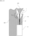
- FIG. 8 is an example illustrating an effect of the tab guide 10 of the present invention.
- the extending guide members 12 of the present invention are formed of a material having elasticity, and thus may be bent without being broken or cracked by an external impact.
- a side surface of the tab guide 10 is pushed by the pressing plate.
- the extending guide members 12 do not have elasticity, a problem of being cracked or broken may have occurred.
- the extending guide members 12 of the present invention are only bent by the pressing plate and may be restored to an original state through elasticity.
- FIG. 9 illustrates a perspective view and a plan view of a tab guide 10 according to a second embodiment of the present invention.
- extending guide members 12 are coupled to the front ends of guide pieces 11a and 11b to be installed to protrude in a frontward direction. That is, rear ends of the extending guide members 12 may be inserted into and coupled to grooves (not shown) formed in upward and downward directions along the front ends of the guide pieces 11a and 11b.
- a spread angle of the extending guide members 12 may be changed according to an angle of the grooves formed at front end portions of the guide pieces 11a and 11b. As described above, the width 12W of the extending guide members formed by the extending guide members 12 may be adjusted by changing the angle of the extending guide members 12.
- inclination angles of the extending guide members 12 may be relatively freely adjusted without being limited to the angle of the guide surfaces 11a30 and 11b30 of the guide member 11.
- a tab guide device of the present invention includes the tab guide of the present invention.
- a plurality of tab guides may be installed side by side along an arrangement direction of a plurality of battery cells.
- the tab guide device is a means capable of simultaneously connecting leads of the battery cells and a tester pin when a large number of battery cells are disposed in a row.
- the tab guide device may further include a connection member in which a plurality of tab guides are slidably installed and extend along the arrangement direction of the battery cells (a transverse direction).
- connection member is a member which passes through one end of the support included in the tab guide and allows the tab guide to move in the transverse direction along the connection member.
- the connection member may have a structure capable of moving the tab guide in the transverse direction, and is not particularly limited in the present invention.
Landscapes
- Physics & Mathematics (AREA)
- General Physics & Mathematics (AREA)
- Engineering & Computer Science (AREA)
- Power Engineering (AREA)
- Manufacturing & Machinery (AREA)
- Electromagnetism (AREA)
- Connection Of Batteries Or Terminals (AREA)
- Battery Mounting, Suspending (AREA)
- Tests Of Electric Status Of Batteries (AREA)
Abstract
Description
- The present invention relates to a tab guide and a tab guide device including the tab guide.
- This application claims the benefit of priority based on
Korean Patent Application No. 10-2021-0169787, filed on December 1, 2021 - A secondary battery is manufactured by injecting an electrolyte, which is a liquid electrolyte, in a state in which an electrode assembly is accommodated in a battery container, and then sealing the battery container.
- In a secondary battery whose manufacturing is completed, various defects due to various causes during an assembly process, a manufacturing process, or use can occur. Among the above, a phenomenon in which a battery whose manufacturing is completed exhibits a voltage drop behavior greater than or equal to a self-discharge rate is called low voltage.
- This low-voltage defect phenomenon is typically caused by metallic foreign substances located in the battery, and representatively, when a metallic foreign material is present in a positive electrode, the metallic foreign substances grow into dendrites at a negative electrode, and these dendrites cause an internal short circuit (short) of the secondary battery. As a result, the internal short circuit of the secondary battery causes a breakdown, damage, ignition, and the like of the secondary battery.
- Specifically, the low-voltage defect phenomenon often occurs during assembly of secondary batteries. Types of assembly defects which cause the low voltage include separator damage such as separator tears, separator folding, separator punctures, or the like. This separator damage mainly occurs at the four corner portions of a cell body during a manufacturing process of the battery.
- Although the above-described defects can cause an internal short circuit, that is, a short circuit in which the positive electrode and the negative electrode come into contact with each other, the positive electrode and the negative electrode are not currently in contact with each other due to a thickness of the separator, but since the short circuit can occur at any time, it is necessary to identify defects by pressing the corresponding portion to cause the internal short circuit.
- Conventionally, in order to quickly and accurately identify the low-voltage defects for a large number of battery cells, a method, in which inspection is possible in a short time by applying jig pressing-type pressing short circuit inspection to a plurality of uncharged battery cells in a short time, or the like is used.
- Meanwhile, in order to determine a short circuit inside the battery cell, a lead of the battery cell should be electrically connected to a tester pin to detect the electrical characteristics of the battery cell in real time, and a tab guide (chuck) or the like which stably guides and connects the lead of the battery cell to the tester pin is used.
-
FIG. 1 illustrates a configuration of a conventional tab guide 10'. Referring toFIG. 1 , a pair ofguide members 11a' and 11b' fixed by a support block 13' have a structure of being spread in a frontward direction, and thus serve to guide alead 210 of abattery cell 200 to a tester pin 20' interposed between theguide members 11a' and 11b' so that thelead 210 of thebattery cell 200 is connected to the tester pin 20'. However, since there is a limitation to a spread angle according to characteristics of the structure of theguide members 11a' and 11b', there is a problem in that awidth 11W' of an insertion portion I' into which thelead 210 of thebattery cell 200 is inserted is formed relatively narrow. InFIG. 2 , problem cases which occur when thelead 210 of thebattery cell 200 is inserted into the tab guide 10' having the same structure asFIG. 1 are shown. As shown inFIG. 2(a) , when thelead 210 of thebattery cell 200 is bent in one direction, a case in which thelead 210 is caught in a process of inserting thelead 210 into the insertion portion I', and thus thelead 210 cannot reach the tester pin 20' can occur (FIG. 2(b) ). Further, a problem in that thelead 210 of thebattery cell 200 is bent at an inlet of the insertion portion I' in the beginning, and thus insertion into the insertion portion I' is impossible can occur (FIG. 2(c) ). - In order to solve the problems caused by the tab guide 10' having the above-described structure in
FIG. 1 , a method of widening thewidth 11W' of the insertion portion I' by increasing the degree of spread of theguide members 11a' and 11b' was also used. -
FIG. 3 illustrates a configuration of a conventional tab guide 10' in which awidth 11W' of an insertion portion of the tab guide 10' is relatively widened. In the tab guide 10' inFIG. 3 , the degree of spread ofguide members 11a'and 11b' is increased, and thus thewidth 11W' of the insertion portion becomes relatively greater than that of the tab guide 10' inFIG. 1 . As the tab guide 10' having the structure inFIG. 3 is used, as shown inFIG. 4(a) , it can be seen that theguide members 11a' and 11b' guide alead 210, which is bent and thus is difficult to be inserted, to a tester pin 20' (FIG. 4(b) ). - However, in the tab guide 10' having the structure in
FIG. 3 , when pressing short circuit inspection for a large number ofbattery cells 200 is performed, a problem in that theguide members 11a' and 11b' collide with theguide members 11a' and 11b' of a neighboring tab guide 10' or a pressing plate 300' and thus are damaged as shown inFIG. 5 due to a unique structure of being spread to side surfaces of the tab guide 10' frequently occurs. -
-
Korean Laid-open Patent No. 10-2020-0059563 -
Japanese Registration Patent No. 6800419 - The present invention is directed to providing a tab guide capable of stably performing electrical characteristic inspection for a large number of battery cells.
- Further, the present invention is directed to providing a tab guide capable of guiding a battery cell lead to a tester pin without damaging the battery cell lead.
- According to the present invention, there is provided a tab guide for guiding an electrode lead of a battery cell to a tester pin for inspection of the battery cell including: a guide member composed of a pair of guide pieces disposed side by side at a predetermined interval and facing each other and having the tester pin installed in the interval, wherein inner side surfaces of the pair of guide pieces facing each other include guide surfaces inclined toward the tester pin from front end portions of the guide pieces; and a pair of extending guide members installed to protrude from the guide member to be inclined away from each other toward the front of the guide member.
- Specifically, rear end portions of the pair of extending guide members may be coupled to the guide surfaces of the guide pieces, and the pair of extending guide members may protrude from the guide member at the same angle as an inclination angle of the guide surfaces.
- Further, the pair of guide pieces may respectively have vertical inner side surfaces extending from the guide surfaces and disposed to face each other in parallel, the tester pin may be fixedly installed between rear end portions of the vertical inner side surfaces facing each other, and front end portions of the vertical inner side surfaces facing each other may form a fixing part configured to fix the electrode lead.
- In addition, outer side surfaces at opposite sides from the inner side surfaces of the pair of guide pieces facing each other may be formed as vertical surfaces extending parallel to the vertical inner side surfaces.
- Meanwhile, the tab guide of the present invention may further include a support block coupled to a rear surface of the guide member.
- Further, the tab guide may further include a support coupled to a lower portion of the support block and formed to extend in a downward direction.
- Specifically, the rear end portions of the pair of extending guide members may be coupled to the front end portions of the guide pieces.
- More specifically, the pair of extending guide members may protrude from the guide member at an angle the same as or different from an inclination angle of the guide surfaces.
- Meanwhile, the guide member and the extending guide members may be formed of different materials.
- For example, the guide member may be formed of a metal material.
- Further, the extending guide members may be formed of a material having elasticity.
- According to the present invention, there is provided a tab guide device including: a plurality of tab guides of the present invention installed side by side along an arrangement direction of a plurality of battery cells; and a connection member installed to allow the plurality of tab guides to slide, and extending along the arrangement direction of the battery cells.
- According to the present invention, in performing pressing short circuit inspection for battery cells, a problem in that a lead of the battery cell does not come into contact with a tester pin and becomes defective can be solved.
- Further, the present invention has an effect in that each tab guide is not damaged and stable short circuit inspection can be performed when the short circuit inspection is performed by pressing a large amount of battery cells.
-
-
FIG. 1 schematically illustrates a perspective view and a plan view of a conventional tab guide. -
FIG. 2 exemplifies problems which occur due to the structure of the tab guide inFIG. 1 . -
FIG. 3 schematically illustrates a perspective view and a plan view of a tab guide in an improved form of the tab guide inFIG. 1 . -
FIG. 4 exemplifies a process of connecting a battery cell lead to the tab guide inFIG. 3 . -
FIG. 5 exemplifies problems which occur due to the structure of the tab guide inFIG. 3 . -
FIG. 6 illustrates a perspective view and a plan view of a guide member and extending guide members of a tab guide according to a first embodiment of the present invention. -
FIG. 7 illustrates a perspective view and a plan view of the tab guide according to the first embodiment of the present invention. -
FIG. 8 is an example illustrating an effect of the tab guide of the present invention. -
FIG. 9 illustrates a perspective view and a plan view of a tab guide according to a second embodiment of the present invention. - Hereinafter, detailed configurations of the present invention will be described in detail with reference to the accompanying drawings and various embodiments. The embodiments to be described below are exemplified for helping understanding of the present invention, and the accompanying drawings are not drawn to an actual scale for helping the understanding of the present invention, and dimensions of some components may be shown to be exaggerated.
- Since the present invention may be variously changed and may have various forms, specific embodiments will be exemplified in the drawings and described in detail in the text. However, it should be understood that this is not intended to limit the present invention to a specific disclosed form, and includes all changes, equivalents, and substitutes included in the spirit and scope of the present invention.
- The present invention relates to a tab guide which guides a lead of a battery cell to a tester pin to inspect the electrical characteristics of the battery cell and the like, and a tab guide device including the tab guide. Specifically, the present invention mainly provides a tab guide in which a width of an insertion portion for a battery cell lead is increased using an extending member of a flexible material.
- Hereinafter, a configuration of a tab guide according to various embodiments of the present invention will be described, and then a configuration of a tab guide device of the present invention will be described with reference to
FIGS. 6 to 8 . - A tab guide of the present invention for guiding an electrode lead of a battery cell to a tester pin for battery cell inspection includes a guide member composed of a pair of guide pieces disposed side by side at a predetermined interval and facing each other and having the tester pin installed in the interval, wherein inner side surfaces of the pair of guide pieces facing each other include guide surfaces inclined toward the tester pin from front end portions of the guide pieces, and a pair of extending guide members installed to protrude from the guide member to be inclined away from each other toward the front of the guide member.
- Specifically, various embodiments may be derived according to the installation position, the shape, and the like of the extending guide member, and hereinafter, tab guides of two embodiments will be described with reference to
FIGS. 6 and9 . -
FIG. 6 illustrates a perspective view and a plan view of aguide member 11 and extendingguide members 12 included in atab guide 10 according to a first embodiment of the present invention. - The tab guide 10 of the present invention includes the
guide member 11 including a pair ofguide pieces electrode lead 210 of abattery cell 200 to atester pin 20, and a pair of extendingguide members 12 installed to protrude from theguide member 11 to be inclined away from each other toward the front of the guide member. - Referring to
FIG. 6 , it can be seen that theguide member 11 is composed of a pair ofguide pieces guide pieces tester pin 20 from front end portions of theguide pieces - The
tester pin 20 of the present invention is a device connected to thelead 210 of thebattery cell 200 to measure the electrical characteristics of thebattery cell 200, and may be disposed to be interposed between the pair ofguide pieces tester pin 20 may be interposed at the rear end portion of theguide member 11. - The
tester pin 20 may be connected to measurement equipment (not shown) for measuring the electrical characteristics of thebattery cell 200 through a conductive wire (not shown), and the like, and the electrical connection between thetester pin 20 and the measurement equipment is not particularly limited in the present invention. - The pair of
guide pieces lead 210 of thebattery cell 200 is inserted. Specifically, the inner side surfaces of theguide pieces tester pin 20 from the front end portions of theguide pieces - In the pair of
guide pieces guide pieces guide pieces 1b 10 of the pair ofguide members 11 is formed to be very narrow. - The
tester pin 20 is fixedly installed between the rear end portions of the vertical inner side surfaces 11a10 and 11b10 facing each other, and the front end portions of the vertical inner side surfaces 11a10 and 11b10 facing each other may form a fixing part F which fixes theelectrode lead 210. - At the front of the
tab guide 10, thelead 210 of thebattery cell 200 inserted to be connected to thetester pin 20 included in thetab guide 10 moves to a correct position (a position facing the tester pin 20) along the guide surfaces 11a30 and 11b30 when not located at the correct position. In this case, thelead 210, which has moved to the correct position along the guide surfaces 11a30 and 11b30, may be fixed by entering the fixing part F, and may come into contact with thetester pin 20. - Outer side surfaces at opposite sides from the inner side surfaces of the pair of
guide pieces guide pieces guide pieces battery cell 200 in a process of performing a pressing short circuit test on a large amount ofbattery cells 200. - The tab guide 10 of the present invention further includes extending
guide members 12 formed of a flexible material and having elasticity. - The extending
guide members 12 are installed on the guide pieces to protrude to the front of theguide member 11. - Specifically, rear end portions of the pair of extending
guide members 12 may be coupled to the guide surface 11a30 and 11b30 of theguide pieces guide members 12 may be formed to protrude from theguide member 11 at the same angle as an inclination angle of the guide surfaces 11a30 and 11b30. - The rear end portions of the pair of extending
guide members 12 may be coupled to the front end portions of theguide pieces - The pair of extending
guide members 12 may be formed to protrude from theguide member 11 at an angle the same as or different from the inclination angle of the guide surfaces 11a30 and 11b30. The inclination angle of the guide surfaces 11a30 and 11b30 is fixed by the design of theguide pieces guide members 12 may be freely changed by adjusting the installation positions and shape of the extendingguide members 12. - Generally, a section between front ends of the
guide member 11 may be a limiting section capable of guiding thelead 210 of thebattery cell 200 to the fixing part F. That is, the probability of guiding thelead 210 of thebattery cell 200 to the fixing part F increases as awidth 11W of the guide member is larger. - In the present invention, the limiting section may be widened through the extending
guide members 12. Specifically, the width between the extendingguide members 12 extending from the guide surfaces 11a30 and 11b30 and protruding to the front of theguide member 11 may be greater than the width between theguide members 11. As a result, since the limiting section capable of guiding thelead 210 of thebattery cell 200 to the fixing part F is larger, the possibility that thetab guide 10 of the present invention guides thelead 210 of thebattery cell 200 to the fixing part F and thelead 210 is connected to thetester pin 20 increases. - In the present invention, the
guide member 11 and the extendingguide members 12 may be formed of different materials. - While the
guide member 11 may be formed of a metal material, the extendingguide members 12 may be formed of a material having elasticity. - The extending
guide members 12 are formed to extend to the guide surfaces 11a30 and 11b30 of theguide member 11 and protrude from theguide member 11, and thus may be directly exposed to external impacts. Accordingly, when a material not having elasticity is used in the extendingguide members 12, damage such as a crack, breaking, or the like of the extendingguide members 12 may occur in the above-described situation. For example, the extendingguide members 12 of the present invention may include a material such as polycarbonate which can recover even from an external impact. - The tab guide 10 of the present invention may further include a
support block 13 coupled to the rear surfaces of theguide member 11 and asupport 14 formed to be coupled to a lower portion of thesupport block 13 to extend in a downward direction. -
FIG. 7 illustrates a perspective view and a plan view of thetab guide 10 of the present invention to which thesupport block 13 and thesupport 14 are applied. - Referring to
FIG. 7 , thetab guide 10 of the present invention includes theguide member 11 formed to extend in a frontward direction where thelead 210 of thebattery cell 200 is located, thesupport block 13 coupled to rear ends of theguide member 11 to fix theguide member 11, and thesupport 14 coupled to the lower portion of thesupport block 13 to extend in the downward direction. - A shape of the
support block 13 is not limited to the drawings shown in the present invention, and may be any shape which can fix theguide member 11 and does not interfere with the insertion of thelead 210 of thebattery cell 200. Further, thesupport 14 is not necessarily limited to the drawings shown in the present invention, and may have a shape capable of supporting thesupport block 13 and moving thesupport block 13 in a lateral direction. -
FIG. 8 is an example illustrating an effect of thetab guide 10 of the present invention. - The extending
guide members 12 of the present invention are formed of a material having elasticity, and thus may be bent without being broken or cracked by an external impact. - Referring to
FIG. 8 , it can be seen that a side surface of thetab guide 10 is pushed by the pressing plate. In this case, when the extendingguide members 12 do not have elasticity, a problem of being cracked or broken may have occurred. However, the extendingguide members 12 of the present invention are only bent by the pressing plate and may be restored to an original state through elasticity. -
FIG. 9 illustrates a perspective view and a plan view of atab guide 10 according to a second embodiment of the present invention. - Referring to
FIG. 9 , it can be seen that extendingguide members 12 are coupled to the front ends ofguide pieces guide members 12 may be inserted into and coupled to grooves (not shown) formed in upward and downward directions along the front ends of theguide pieces - A spread angle of the extending
guide members 12 may be changed according to an angle of the grooves formed at front end portions of theguide pieces width 12W of the extending guide members formed by the extendingguide members 12 may be adjusted by changing the angle of the extendingguide members 12. - When the
tab guide 10 has the structure shown inFIG. 9 , inclination angles of the extendingguide members 12 may be relatively freely adjusted without being limited to the angle of the guide surfaces 11a30 and 11b30 of theguide member 11. - A tab guide device of the present invention includes the tab guide of the present invention.
- Specifically, in the tab guide device, a plurality of tab guides may be installed side by side along an arrangement direction of a plurality of battery cells.
- The tab guide device is a means capable of simultaneously connecting leads of the battery cells and a tester pin when a large number of battery cells are disposed in a row.
- The tab guide device may further include a connection member in which a plurality of tab guides are slidably installed and extend along the arrangement direction of the battery cells (a transverse direction).
- The connection member is a member which passes through one end of the support included in the tab guide and allows the tab guide to move in the transverse direction along the connection member. The connection member may have a structure capable of moving the tab guide in the transverse direction, and is not particularly limited in the present invention.
- In the above, the present invention has been described in more detail with reference to the drawings, examples, and the like. However, since the configuration described in the drawings, embodiments, or the like described in the present specification is only one embodiment of the present invention and does not represent all the technical spirit of the present invention, it should be understood that there may be various equivalents and modifications at the time of filing the present application.
-
- 10: tab guide
- 10': (Related art) tab guide
- 11: guide members
- 11W: guide members width
- 11W': (Related art) insertion portion width
- 11a, 11b: guide pieces
- 11a', 11b': (Related art) guide members
- 11a10, 11b10: vertical inner side surface
- 11a30, 11b30: guide surface
- 12: extending guide members
- 12W: extending guide members width
- 13: support block
- 13': (Related art) support block
- 14: support
- 20: tester pin
- 20': (Related art) tester pin
- 200: battery cell
- 210: lead
- 300: pressing plate
- 300': (Related art) pressing plate
- F: fixing part
- I': (Related art) insertion portion
- I: insertion portion
Claims (12)
- A tab guide for guiding an electrode lead of a battery cell to a tester pin for inspection of the battery cell, the tab guide comprising:a guide member composed of a pair of guide pieces disposed side by side at a predetermined interval and facing each other and having the tester pin installed in the interval, wherein inner side surfaces of the pair of guide pieces facing each other include guide surfaces inclined toward the tester pin from front end portions of the guide pieces; anda pair of extending guide members installed to protrude from the guide member to be inclined away from each other toward a front of the guide member.
- The tab guide of claim 1, wherein rear end portions of the pair of extending guide members are coupled to the guide surfaces of the guide pieces, and the pair of extending guide members protrude from the guide member at the same angle as an inclination angle of the guide surfaces.
- The tab guide of claim 1, wherein:the pair of guide pieces respectively have vertical inner side surfaces extending from the guide surfaces and disposed to face each other in parallel;the tester pin is fixedly installed between rear end portions of the vertical inner side surfaces facing each other; andfront end portions of the vertical inner side surfaces facing each other form a fixing part configured to fix the electrode lead.
- The tab guide of claim 1, further comprising a support block coupled to a rear surface of the guide member.
- The tab guide of claim 3, wherein outer side surfaces at opposite sides from the inner side surfaces of the pair of guide pieces facing each other are formed as vertical surfaces extending parallel to the vertical inner side surfaces.
- The tab guide of claim 1, wherein rear end portions of the pair of extending guide members are coupled to the front end portions of the guide pieces.
- The tab guide of claim 6, wherein the pair of extending guide members protrude from the guide member at an angle the same as or different from an inclination angle of the guide surfaces.
- The tab guide of claim 1, wherein the guide member and the extending guide members are formed of different materials.
- The tab guide of claim 1, wherein the guide member is formed of a metal material.
- The tab guide of claim 1, wherein the extending guide members are formed of a material having elasticity.
- The tab guide of claim 4, further comprising a support coupled to a lower portion of the support block and formed to extend in a downward direction.
- A tab guide device comprising:a plurality of tab guides of any one of claims 1 to 11 installed side by side along an arrangement direction of a plurality of battery cells; anda connection member in which the plurality of tab guides are slidably installed and extending along the arrangement direction of the battery cells.
Applications Claiming Priority (2)
| Application Number | Priority Date | Filing Date | Title |
|---|---|---|---|
| KR1020210169787A KR20230082138A (en) | 2021-12-01 | 2021-12-01 | A tab guide and a tab guide device including the tab guide |
| PCT/KR2022/019167 WO2023101394A1 (en) | 2021-12-01 | 2022-11-30 | Tab guide and tab guide device comprising tab guide |
Publications (2)
| Publication Number | Publication Date |
|---|---|
| EP4328600A1 true EP4328600A1 (en) | 2024-02-28 |
| EP4328600A4 EP4328600A4 (en) | 2025-03-19 |
Family
ID=86612643
Family Applications (1)
| Application Number | Title | Priority Date | Filing Date |
|---|---|---|---|
| EP22901752.0A Pending EP4328600A4 (en) | 2021-12-01 | 2022-11-30 | Tab guide and tab guide device with tab guide |
Country Status (6)
| Country | Link |
|---|---|
| US (1) | US20250052828A1 (en) |
| EP (1) | EP4328600A4 (en) |
| JP (1) | JP7596618B2 (en) |
| KR (1) | KR20230082138A (en) |
| CN (1) | CN117396768A (en) |
| WO (1) | WO2023101394A1 (en) |
Family Cites Families (15)
| Publication number | Priority date | Publication date | Assignee | Title |
|---|---|---|---|---|
| JPH07105224B2 (en) * | 1992-03-23 | 1995-11-13 | 日本碍子株式会社 | Terminal connection device for sodium-sulfur battery |
| JP2000100480A (en) | 1998-09-28 | 2000-04-07 | Kataoka Seisakusho:Kk | Electrode contact device and electrode contact method for thin battery |
| JP2002134176A (en) | 2000-10-30 | 2002-05-10 | Mikuni Kogyo:Kk | Charge / discharge / inspection mechanism for lithium polymer batteries |
| JP2011018523A (en) * | 2009-07-08 | 2011-01-27 | Sumitomo Wiring Syst Ltd | Connector |
| KR101384636B1 (en) * | 2012-08-27 | 2014-04-14 | 인지컨트롤스 주식회사 | Sensing module for secondary battery |
| JP6088054B2 (en) * | 2013-08-14 | 2017-03-01 | 日産自動車株式会社 | Film exterior battery insertion guide device |
| KR20150050210A (en) * | 2013-10-31 | 2015-05-08 | 주식회사 엘지화학 | Apparatus for protecting electrode tab and secondary battery including the same |
| KR20180085664A (en) * | 2017-01-19 | 2018-07-27 | 타이코에이엠피 주식회사 | Battery cell sensing device and battery package comprising the same |
| JP6800419B2 (en) | 2017-02-03 | 2020-12-16 | 株式会社エンビジョンAescジャパン | Chuck device |
| KR102716515B1 (en) * | 2017-02-06 | 2024-10-14 | 에이치그린파워 주식회사 | Voltage sensing housing structure and battery module including the same |
| PL3683589T3 (en) | 2018-06-11 | 2023-05-22 | Lg Energy Solution, Ltd. | Simultaneous inspection device of multiple secondary battery cell pouches |
| CN209182476U (en) * | 2018-11-02 | 2019-07-30 | 湖北德普智能装备有限公司 | A kind of slide type battery measuring device |
| KR102408132B1 (en) | 2018-11-21 | 2022-06-14 | 주식회사 엘지에너지솔루션 | Method for testing pressure short defect by jig pressing |
| KR102509603B1 (en) * | 2019-09-18 | 2023-03-10 | 주식회사 엘지에너지솔루션 | Apparatus for detecting a low voltage pouch type secondary battery cell |
| KR102130939B1 (en) * | 2020-04-14 | 2020-07-07 | 주식회사 에스에이치엘 | Electrode connection unit for preventing electrode damage |
-
2021
- 2021-12-01 KR KR1020210169787A patent/KR20230082138A/en not_active Ceased
-
2022
- 2022-11-30 CN CN202280037997.0A patent/CN117396768A/en active Pending
- 2022-11-30 US US18/564,369 patent/US20250052828A1/en active Pending
- 2022-11-30 EP EP22901752.0A patent/EP4328600A4/en active Pending
- 2022-11-30 JP JP2023572214A patent/JP7596618B2/en active Active
- 2022-11-30 WO PCT/KR2022/019167 patent/WO2023101394A1/en not_active Ceased
Also Published As
| Publication number | Publication date |
|---|---|
| JP7596618B2 (en) | 2024-12-10 |
| JP2024519127A (en) | 2024-05-08 |
| EP4328600A4 (en) | 2025-03-19 |
| CN117396768A (en) | 2024-01-12 |
| US20250052828A1 (en) | 2025-02-13 |
| KR20230082138A (en) | 2023-06-08 |
| WO2023101394A1 (en) | 2023-06-08 |
Similar Documents
| Publication | Publication Date | Title |
|---|---|---|
| KR101288647B1 (en) | Secondary battery tester, secondary battery testing method, and manufacturing method of secondary battery | |
| KR100823695B1 (en) | Test structure for inspection of allowable process error of integrated circuit and method for inspection of allowable process error using same | |
| US9201093B2 (en) | Inspection apparatus for semiconductor device | |
| CN207965096U (en) | A kind of battery core detection fixture and detection device | |
| CN116710766B (en) | Equipment for detecting foreign object locations in low-voltage battery cells and analytical methods using the equipment | |
| KR20190039122A (en) | Contact probes and corresponding test heads of devices for testing electronic devices | |
| US7301354B2 (en) | Contact probe for a testing head having vertical probes for semiconductor integrated devices | |
| CN114556093A (en) | Welding quality inspection device | |
| KR102257278B1 (en) | Electrical connection device | |
| CN116323414B (en) | Inspection device and inspection method for poor assembly of battery cell activation tray or distortion during operation | |
| KR200481194Y1 (en) | Contact device for electrical test | |
| US20250052828A1 (en) | Tab Guide and Tab Guide Device Comprising Tab Guide | |
| US20060103408A1 (en) | Semiconductor wafer and testing method therefor | |
| US20250028004A1 (en) | Battery module charge and discharge inspection system and method thereof | |
| US20230204480A1 (en) | Battery cell weld portion inspection apparatus and battery cell weld portion inspection method using the same | |
| KR20040022004A (en) | Probe for testing secondary battery | |
| KR100652421B1 (en) | Donut type parallel probe card and wafer inspection method using the same | |
| JP7733737B2 (en) | Apparatus and method for detecting internal defects in battery cells using TDR | |
| KR101778673B1 (en) | A Inspection Device for Battery Packs with Various Length and Thickness | |
| CN115516693B (en) | Device for inspecting defect of electrode assembly before electrolyte injection and defect inspection method thereof | |
| US10935570B2 (en) | Intermediate connection member and inspection apparatus | |
| KR100466483B1 (en) | Socket apparatus for ic packages | |
| US20240302437A1 (en) | Secondary Battery Cell Insulation Test Apparatus and Method Using the Same | |
| US20250067816A1 (en) | Apparatus for checking for short circuits | |
| KR102555637B1 (en) | apparatus for inspecting insulation of prismatic secondary battery |
Legal Events
| Date | Code | Title | Description |
|---|---|---|---|
| STAA | Information on the status of an ep patent application or granted ep patent |
Free format text: STATUS: THE INTERNATIONAL PUBLICATION HAS BEEN MADE |
|
| PUAI | Public reference made under article 153(3) epc to a published international application that has entered the european phase |
Free format text: ORIGINAL CODE: 0009012 |
|
| STAA | Information on the status of an ep patent application or granted ep patent |
Free format text: STATUS: REQUEST FOR EXAMINATION WAS MADE |
|
| 17P | Request for examination filed |
Effective date: 20231124 |
|
| AK | Designated contracting states |
Kind code of ref document: A1 Designated state(s): AL AT BE BG CH CY CZ DE DK EE ES FI FR GB GR HR HU IE IS IT LI LT LU LV MC ME MK MT NL NO PL PT RO RS SE SI SK SM TR |
|
| DAV | Request for validation of the european patent (deleted) | ||
| DAX | Request for extension of the european patent (deleted) | ||
| A4 | Supplementary search report drawn up and despatched |
Effective date: 20250213 |
|
| RIC1 | Information provided on ipc code assigned before grant |
Ipc: G01R 31/56 20200101ALI20250207BHEP Ipc: G01R 31/36 20200101ALI20250207BHEP Ipc: G01R 31/52 20200101ALI20250207BHEP Ipc: G01R 31/00 20060101ALI20250207BHEP Ipc: G01R 31/385 20190101AFI20250207BHEP |
|
| STAA | Information on the status of an ep patent application or granted ep patent |
Free format text: STATUS: EXAMINATION IS IN PROGRESS |
|
| 17Q | First examination report despatched |
Effective date: 20251008 |