EP4328456A1 - Axial flow wind wheel, air conditioner outdoor unit, and air conditioner - Google Patents
Axial flow wind wheel, air conditioner outdoor unit, and air conditioner Download PDFInfo
- Publication number
- EP4328456A1 EP4328456A1 EP22854935.8A EP22854935A EP4328456A1 EP 4328456 A1 EP4328456 A1 EP 4328456A1 EP 22854935 A EP22854935 A EP 22854935A EP 4328456 A1 EP4328456 A1 EP 4328456A1
- Authority
- EP
- European Patent Office
- Prior art keywords
- flow guide
- wind wheel
- axial flow
- blade
- flow wind
- Prior art date
- Legal status (The legal status is an assumption and is not a legal conclusion. Google has not performed a legal analysis and makes no representation as to the accuracy of the status listed.)
- Pending
Links
Images


Classifications
-
- F—MECHANICAL ENGINEERING; LIGHTING; HEATING; WEAPONS; BLASTING
- F04—POSITIVE - DISPLACEMENT MACHINES FOR LIQUIDS; PUMPS FOR LIQUIDS OR ELASTIC FLUIDS
- F04D—NON-POSITIVE-DISPLACEMENT PUMPS
- F04D29/00—Details, component parts, or accessories
- F04D29/66—Combating cavitation, whirls, noise, vibration or the like; Balancing
- F04D29/68—Combating cavitation, whirls, noise, vibration or the like; Balancing by influencing boundary layers
- F04D29/681—Combating cavitation, whirls, noise, vibration or the like; Balancing by influencing boundary layers especially adapted for elastic fluid pumps
-
- F—MECHANICAL ENGINEERING; LIGHTING; HEATING; WEAPONS; BLASTING
- F04—POSITIVE - DISPLACEMENT MACHINES FOR LIQUIDS; PUMPS FOR LIQUIDS OR ELASTIC FLUIDS
- F04D—NON-POSITIVE-DISPLACEMENT PUMPS
- F04D29/00—Details, component parts, or accessories
- F04D29/26—Rotors specially for elastic fluids
- F04D29/32—Rotors specially for elastic fluids for axial flow pumps
- F04D29/325—Rotors specially for elastic fluids for axial flow pumps for axial flow fans
-
- F—MECHANICAL ENGINEERING; LIGHTING; HEATING; WEAPONS; BLASTING
- F04—POSITIVE - DISPLACEMENT MACHINES FOR LIQUIDS; PUMPS FOR LIQUIDS OR ELASTIC FLUIDS
- F04D—NON-POSITIVE-DISPLACEMENT PUMPS
- F04D19/00—Axial-flow pumps
- F04D19/002—Axial flow fans
-
- F—MECHANICAL ENGINEERING; LIGHTING; HEATING; WEAPONS; BLASTING
- F04—POSITIVE - DISPLACEMENT MACHINES FOR LIQUIDS; PUMPS FOR LIQUIDS OR ELASTIC FLUIDS
- F04D—NON-POSITIVE-DISPLACEMENT PUMPS
- F04D29/00—Details, component parts, or accessories
- F04D29/26—Rotors specially for elastic fluids
- F04D29/32—Rotors specially for elastic fluids for axial flow pumps
- F04D29/38—Blades
- F04D29/384—Blades characterised by form
-
- F—MECHANICAL ENGINEERING; LIGHTING; HEATING; WEAPONS; BLASTING
- F04—POSITIVE - DISPLACEMENT MACHINES FOR LIQUIDS; PUMPS FOR LIQUIDS OR ELASTIC FLUIDS
- F04D—NON-POSITIVE-DISPLACEMENT PUMPS
- F04D29/00—Details, component parts, or accessories
- F04D29/66—Combating cavitation, whirls, noise, vibration or the like; Balancing
- F04D29/661—Combating cavitation, whirls, noise, vibration or the like; Balancing especially adapted for elastic fluid pumps
- F04D29/666—Combating cavitation, whirls, noise, vibration or the like; Balancing especially adapted for elastic fluid pumps by means of rotor construction or layout, e.g. unequal distribution of blades or vanes
-
- F—MECHANICAL ENGINEERING; LIGHTING; HEATING; WEAPONS; BLASTING
- F04—POSITIVE - DISPLACEMENT MACHINES FOR LIQUIDS; PUMPS FOR LIQUIDS OR ELASTIC FLUIDS
- F04D—NON-POSITIVE-DISPLACEMENT PUMPS
- F04D29/00—Details, component parts, or accessories
- F04D29/66—Combating cavitation, whirls, noise, vibration or the like; Balancing
- F04D29/661—Combating cavitation, whirls, noise, vibration or the like; Balancing especially adapted for elastic fluid pumps
- F04D29/667—Combating cavitation, whirls, noise, vibration or the like; Balancing especially adapted for elastic fluid pumps by influencing the flow pattern, e.g. suppression of turbulence
-
- F—MECHANICAL ENGINEERING; LIGHTING; HEATING; WEAPONS; BLASTING
- F24—HEATING; RANGES; VENTILATING
- F24F—AIR-CONDITIONING; AIR-HUMIDIFICATION; VENTILATION; USE OF AIR CURRENTS FOR SCREENING
- F24F1/00—Room units for air-conditioning, e.g. separate or self-contained units or units receiving primary air from a central station
- F24F1/06—Separate outdoor units, e.g. outdoor unit to be linked to a separate room comprising a compressor and a heat exchanger
- F24F1/38—Fan details of outdoor units, e.g. bell-mouth shaped inlets or fan mountings
-
- F—MECHANICAL ENGINEERING; LIGHTING; HEATING; WEAPONS; BLASTING
- F05—INDEXING SCHEMES RELATING TO ENGINES OR PUMPS IN VARIOUS SUBCLASSES OF CLASSES F01-F04
- F05D—INDEXING SCHEME FOR ASPECTS RELATING TO NON-POSITIVE-DISPLACEMENT MACHINES OR ENGINES, GAS-TURBINES OR JET-PROPULSION PLANTS
- F05D2240/00—Components
- F05D2240/20—Rotors
- F05D2240/30—Characteristics of rotor blades, i.e. of any element transforming dynamic fluid energy to or from rotational energy and being attached to a rotor
- F05D2240/306—Characteristics of rotor blades, i.e. of any element transforming dynamic fluid energy to or from rotational energy and being attached to a rotor related to the suction side of a rotor blade
Definitions
- the present application relates to the technical field of cooling devices, and in particular, to an axial flow wind wheel, an air conditioner outdoor unit, and an air conditioner.
- an axial flow wind wheel provides air volume required for heat transfer for a heat exchanger of the outdoor unit.
- the axial flow wind wheel includes a wheel hub and a plurality of blades arranged along a circumferential direction of the wheel hub. During operation of the axial flow wind wheel, there is a phenomenon of air flow separation on surfaces of the blades, which leads to decrease of air outflow volume of the axial flow wind wheel and increase of operation noise.
- a main object of the present application is to provide an axial flow wind wheel, an air conditioner outdoor unit and an air conditioner, which aims to solve the technical problem that the air outflow volume of the axial flow wind wheel is decreased and the operation noise is increased due to the phenomenon of air flow separation on the surfaces of the blades during operation of the existing axial flow wind wheel.
- the axial flow wind wheel provided in the present application includes a wheel hub and a plurality of blades; wherein the plurality of blades are uniformly arranged at intervals in a circumferential direction of the wheel hub, and inner edges of the blades are connected to the wheel hub; the axial flow wind wheel further includes a plurality of virtual circumferential lines which are concentric and arranged at intervals, and centers of circles of the virtual circumferential lines coincide with an axis of the wheel hub; and areas of suction surfaces of the blades corresponding to the virtual circumferential lines are provided with flow guide structures arranged along the virtual circumferential lines.
- the axial flow wind wheel provided in the present application includes a wheel hub and a plurality of blades uniformly arranged at intervals in the circumferential direction of the wheel hub, and the suction surface of each blade is provided with a plurality of rows of flow guide structures, and each row of flow guide structures includes a plurality of flow guide ribs and the plurality of flow guide ribs are arranged along an arc corresponding thereto; and the arcs corresponding to the rows of flow guide structures are concentric with the axis of the wheel hub, and are arranged at intervals in a radial direction of the wheel hub.
- the flow guide structures can disperse the air flow separated from the suction surfaces of the blades, so that the dispersed air flow is uniformly dispersed, and the dispersed air flow is re-attached to the suction surfaces, so as to reduce noise of air flow and increase an air supply volume of the wind wheel.
- the number of rows of flow guide structures included in the suction surfaces of any two blades is the same and the flow guide structures included in the suction surfaces of any two blades are in one-to-one correspondence.
- radii of the arcs corresponding to corresponding two rows of flow guide structures are the same in the suction surfaces of any two blades.
- a row spacing of any adjacent rows of flow guide structures is equal along a radial direction of the wheel hub on the suction surface of a same blade.
- the row spacing of adjacent rows of flow guide structures gradually increases or decreases along the radial direction of the wheel hub on the suction surface of a same blade.
- a spacing between adjacent flow guide ribs is equal along a direction from a leading edge of the blades to a trailing edge thereof.
- a spacing between adjacent flow guide ribs gradually increases or decreases along a direction from a leading edge of the blade to a trailing edge thereof.
- the lengths of flow guide ribs included in the same row of the flow guide structure gradually increase along a direction from an inner edge of the blade to an outer edge thereof.
- lengths of the flow guide ribs included in a row of the flow guide structure closest to the inner edge of the blade are ⁇ D/500, where D is a diameter of the axial flow wind wheel.
- lengths of each flow guide ribs included in a row of the flow guide structure closest to the outer edge of the blade are ⁇ D/50, where D is a diameter of the axial flow wind wheel.
- the flow guide ribs include one of a rectangular flow guide rib, triangular flow guide rib and circular flow guide rib, or a combination thereof.
- the present application further provides an air conditioner outdoor unit, including a heat exchanger, a driving motor, and the axial flow wind wheel according to any one of the above technical solutions, wherein the heat exchanger is arranged opposite to the axial flow wind wheel, and a driving shaft of the driving motor is connected with the wheel hub of the axial flow wind wheel.
- the present application further provides an air conditioner, including the above air conditioner outdoor unit.
- the axial flow wind wheel provides air volume required for heat transfer for the heat exchanger of the outdoor unit.
- the suction surface of the blade is relatively smooth, there is a phenomenon of air flow separation on the suction surface of the blade during the operation of the axial flow wind wheel, which leads to a decreased air outflow volume of the axial flow wind wheel and increased operation noise.
- each row of flow guide structure includes a plurality of flow guide ribs, and the plurality of flow guide ribs are arranged along an arc corresponding thereto; the arcs corresponding to the rows of flow guide structures are concentric with the axis of the wheel hub, and are arranged at intervals along the radial direction of the wheel hub.
- the flow guide structure can disperse the air flow separated from the suction surface of the blade, so that the dispersed air flow is uniformly dispersed and re-attached to the suction surface, so as to reduce noise of the air flow and increase air supply volume of the wind wheel.
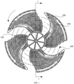
- FIG. 1 is a front view of an axial flow wind wheel provided by Embodiment 1 of the present application
- FIG. 2 is a side view of the axial flow wind wheel provided by Embodiment 1 of the present application
- FIG. 3 is a sectional view taken along A-A of FIG. 1 .
- the axial flow wind wheel provided by the embodiment of the present application includes a wheel hub 100 and a plurality of blades 200, where the plurality of blades 200 are each arranged on the wheel hub 100, and the wheel hub 100 can drive the blades 200 to rotate under an action of steering force to realize a function of wind supply.
- the plurality of blades 200 may be uniformly arranged at intervals in a circumferential direction of the wheel hub, for example, the axial flow wind wheel may include four blades 200, the four blades 200 surround a central axis of the wheel hub 100 and are arranged at equal intervals on a circumferential wall of the wheel hub 100 in a counterclockwise direction (such as the counterclockwise direction indicated by the arrow shown in FIG. 1 ).
- Each blade 200 includes an inner edge 201, an outer edge 202, a leading edge 203 and a trailing edge 204. Specifically, along a rotation direction (as indicated by the arrow shown in FIG. 1 ) of the axial flow wind wheel, a front side edge of the blade 200 forms the leading edge 203 of the blade 200, and a rear side edge of the blade 200 forms the trailing edge 204 of the blade 200, and the leading edge 203 and the trailing edge 204 of the blade 200 are arranged opposite to each other.
- the outer edge 202 of the blade 200 is formed by an outer side edge connecting the trailing edge 204 and the leading edge 203 in the same blade 200
- the inner edge 201 of the blade 200 is formed by an inside side edge connecting the trailing edge 204 and the leading edge 203 in the same blade 200.
- each blade 200 also includes a suction surface 205 and a pressure surface 206 formed on both side surfaces of the wheel hub 100 in an axial direction.
- each blade 200 is provided with a plurality of rows of flow guide structures 300 respectively, and among the plurality of rows of flow guide structures 300 arranged on the suction surface of the same blade 200, each row of flow guide structure 300 includes a plurality of flow guide ribs 301 arranged along a same arc 400; the arc 400 extends in the direction from the leading edge 203 to the trailing edge 204 of the blade 200.
- the plurality of flow guide structures 300 are respectively arranged on different arcs 400, each arc 400 is concentric with the axis of the wheel hub 100, and the arcs 400 are arranged at intervals along a radial direction of the wheel hub 100, or the arcs 400 are arranged at intervals along a direction of the trailing edge 201 to the leading edge 203 of the blade 200.
- each flow guide structure 300 is provided with a plurality of flow guide structures 300 on the suction surface 205 of each blade 200, the plurality of flow guide structures 300 are distributed to be concentric with the axis of the wheel hub 100, and a plurality of arcs 400 are arranged at intervals along the radial direction of the wheel hub 100, and each flow guide structure 300 is provided with a plurality of flow guide ribs 301 on its corresponding arc 400.
- the flow guide rib 301 can play a role of disturbing flow during the rotation of the axial flow wind wheel, and can disperse the air flow separated from the suction surface 205, so that the air flow after dispersion is uniformly dispersed and re-attached with the suction surface 205, which can reduce noise of the air flow during rotation of the axial flow wind wheel and increase the air supply volume of the axial flow wind wheel.
- the axial flow wind wheel includes a plurality of blades 200 arranged at intervals along its circumferential direction, each blade 200 is arranged with a plurality of rows of flow guide structures 300 along the inner edge 201 and the outer edge 202 of the blade 200.
- the suction surfaces 205 of any two blades 200 are provided with the same number of rows of flow guide structures 300 in one-to-one correspondence.
- the axial flow wind wheel may include a first blade and a second blade adj acent to the first blade, and the number of flow guide structures 300 provided on the first blade is the same as the number of flow guide structures 300 provided on the second blade, and the flow guide structures 300 on the first blade may be staggered with the flow guide structures 300 on the second blade.
- the number of flow guide structures 300 arranged on the suction surface of the first blade is the same as the number of flow guide structures 300 arranged on the suction surface of the second blade.
- arcs 400 corresponding to the two flow guide structures have the same radius, that is, the arcs 400 corresponding to the two corresponding flow guide structures 300 are on a same circle.
- the flow guide structure 300 includes a plurality of flow guide ribs 301 located on the same arc 400.
- the flow guide ribs 301 provided in the present embodiment can be formed by local bulges on the suction surface 205 of the blade 200, and the flow guide ribs 301 have a certain thickness, and the thickness is a height of the flow guide ribs 301 along the axial direction of the wheel hub 100.
- the thicknesses of the flow guide ribs 301 located on the same arc 400 may be the same or different, and if the thicknesses of the flow guide ribs 301 located on the same arc 400 are different, the thicknesses of the flow guide ribs 301 located on the same arc 400 are gradually increased or decreased in a direction from the leading edge 203 to the trailing edge 204 of the blade 200, and this is not limited in the present embodiment and can be set according to the actual needs.
- a length direction of the flow guide ribs 301 on the suction surface 205 is the same as an extension direction of the arc 400 on the suction surface 205 of the blade 200, and lengths of the flow guide ribs 301 located on the same arc 400 can be the same or different; this is not limited in the present embodiment and can be set according to the actual needs.
- the present embodiment does not restrict the shape of the flow guide ribs 301, for example, the flow guide ribs 301 in the present embodiment may include one of rectangular flow guide ribs 301, triangular flow guide ribs 301, circular flow guide ribs 301 or any combination of the above three.
- the extension lengths of the flow guide ribs 301 on the suction surface 205 are projection lengths of the flow guide ribs on respective arcs 400.
- the flow guide ribs 301 are the circular flow guide ribs, their extension lengths on the suction surface 205 in the direction from the leading edge 203 to the trailing edge 204 of the blade 200 are the projection lengths of their diameters on the arc 400.
- the flow guide ribs 301 are the triangular flow guide ribs, for example, equilateral triangle guide ribs, their extension lengths on the suction surface 205 in the direction from the leading edge 203 to the trailing edge 204 of the blade 200 are the projection lengths of their side lengths on the arc 400.
- the flow guide ribs 301 are the rectangular flow guide ribs, their extension lengths on the suction surface 205 in the direction from the leading edge 203 to the trailing edge 204 of the blade 200 are their projection lengths on the arc 400.
- the present embodiment is illustrated by an example in which the suction surface 205 is provided with rectangular flow guide ribs, and for a plurality of flow guide ribs 301 arranged on the same arc 400, the flow guide ribs 301 have a same thickness and the flow guide ribs 301 have a same length on the arc 400.
- FIG. 4 is a schematic diagram of an arrangement of the flow guide structure in FIG. 1 on the suction surface of the blade;
- FIG. 5 is an enlarged diagram at B in FIG. 3 .
- spacings between adjacent flow guide ribs 301 located on the same arc 400 may be equal in the present embodiment. In other embodiments, the spacings between adjacent flow guide ribs 301 arranged on the suction surface 205 of the same blade 200 and located on the same arc 400 may be unequal.
- FIG. 6 is a schematic diagram of change of a spacing between a plurality of flow guide ribs located on the same arc 400 in the present embodiment of the present application
- FIG. 7 is another schematic diagram of change of the spacing between the plurality of flow guide ribs located on the same arc 400 in the present embodiment of the present application.
- the spacings between adjacent flow guide ribs 301 located in the same row are gradually decreased, that is, along the leading edge 203 of the blade 200 to the trailing edge 204 of the blade 200, the spacings between adjacent flow guide ribs 301 located on the same arc 400 are gradually decreased.
- the present embodiment can also, according to different actual needs, gradually increase the spacings between adjacent flow guide ribs 301 located on the suction surface 205 of the same blade 200 and arranged on the same row; that is, the spacings between adjacent flow guide ribs 301 located on the same arc 400 along the direction from the leading edge 203 of the blade 200 to the trailing edge 204 of the blade 200 are increased gradually, and the present embodiment has no limit on this.
- the plurality of rows of flow guide structures are arranged at intervals on the suction surface of the blade 200, and the lengths of the flow guide ribs 301 located on different rows are different.
- the lengths of the flow guide ribs 301 included in the same row of flow guide structure 300 increase gradually along the direction from the inner edge 201 to the outer edge 202 of the blade 200.
- the lengths of the flow guide ribs 301 on the arc 400 near the inner edge 201 of the blade 200 are limited; for example, in a row of flow guide structure 300 closest to the inner edge 201 of the blade 200, the length of each flow guide rib 301 included is ⁇ D/500, where D is the diameter of the axial flow wind wheel.
- the length of the flow guide ribs 301 on the arc 400 near the outer edge 201 of the blade 200 are also limited; for example, in a row of flow guide structure 300 closest to the outer edge of the blade 200, the length of each flow guide rib included is ⁇ 50/D, where D is the diameter of the axial flow wind wheel.
- the spacings between adjacent rows of flow guide structures 300 along the radial direction of the wheel hub 100 are equal, that is, along the direction from the inner edge 201 to the outer edge 202 of the blade 200, in the plurality of flow guide structures 300 arranged at intervals on the suction surface 205 of the blade 200, the spacings between adjacent flow guide structures 300 are equal.
- the spacings between adjacent rows of flow guide structures 300 along the radial direction of the wheel hub 100 are not equal, that is, along the direction from the inner edge 201 to the outer edge 202 of the blade 200, the spacings between adjacent flow guide structures 300 are not equal.
- FIG. 8 is a schematic diagram of unequal interval distribution of a plurality of arcs in the axial flow wind wheel in the present embodiment
- FIG. 9 is another schematic diagram of unequal interval distribution of a plurality of arcs in the axial flow wind wheel in the present embodiment.
- row spacings between adjacent rows of flow guide structures 300 can be gradually decreased along the direction from the inner edge 201 to the outer edge 202 of the blade 200.
- the spacings between adjacent flow guide structures 300 can be gradually increased along the inner edge 201 to the outer edge 202 of the blade 200 according to different actual needs. The present embodiment has no limit on this.
- the embodiment of the present application provides an air conditioner outdoor unit (that is, outdoor unit of air conditioner), including a driving motor, a heat exchanger, and the axial flow wind wheel of Embodiment 1; where a driving shaft of the driving motor is connected with the wheel hub 100 of the axial flow wind wheel, and the axial flow wind wheel is arranged opposite to the heat exchanger, the driving motor drives the axial flow wind wheel to rotate, and the axial flow wind wheel can provide an air volume required for heat exchange of the heat exchanger.
- the embodiment of the present application provides an air conditioner, which includes the air conditioner outdoor unit in Embodiment 2, the outdoor unit including a heat exchanger, and the heat exchanger in the present application may be a microchannel heat exchanger.
- the microchannel heat exchanger includes at least two sets of microchannels.
- the at least two sets of microchannels include a plurality of first microchannels for a first cold medium flow to flow and a plurality of second microchannels for a second cold medium flow to flow.
- the second cold medium flow absorbs heat from the first cold medium flow so that the first cold medium flow is supercooled, or the first cold medium flow absorbs heat from the second cold medium flow so that the second cold medium flow is supercooled.
- the microchannel heat exchanger of the embodiment of the present application can also be used as an economizer of the air conditioner.
- the microchannel heat exchanger can not only be used to cool electronic components in an electric control box, but also can be used as an economizer, so as to avoid setting another economizer outside the electric control box, simplifying the structure of the air conditioner, saving space and saving cost.
- the outdoor unit adopts the technical solution of the above Embodiment 1, it owns at least all the beneficial effects brought by the technical solution of the above Embodiment 1, and the effects will not be repeated here.
- orientation or position relationships indicated by the terms such as “center”, “length”, “width”, “thickness”, “front”, “rear”, “inner”, “outer”, “clockwise”, “counterclockwise”, “axial”, “radial” and “circumferential” are based on the orientation or position relationships shown in the drawings, only to facilitate the description of the present application and simplify the description, rather than indicating or implying that the device or element referred to must have a specific orientation or be constructed and operated in a specific direction, and thus they cannot be understood as a restriction on the present application.
- a first feature being “above” or “below” a second feature may be a direct contact of the first feature with the second feature, or indirect contact of the first feature with the second feature through an intermediate medium.
- the first feature being “above”, “on” and “over” the second feature may be that the first feature is directly above or obliquely above the second feature, or only that a horizontal height of the first feature is higher than that of the second feature.
- the first feature being “under”, “below” and “lower” the second feature may be that the first feature is directly below or obliquely below the second feature, or simply that the horizontal height of the first feature is less than that of the second feature.
- Air conditioner inner unit of the present application is described in conjunction with a wall-mounted air-conditioner inner unit, but this is not a limitation. Air conditioner inner unit of other equipment can also be equipped with the air conditioner inner unit of the present application, such as cabinet-type air conditioner inner unit.
Landscapes
- Engineering & Computer Science (AREA)
- Mechanical Engineering (AREA)
- General Engineering & Computer Science (AREA)
- Chemical & Material Sciences (AREA)
- Combustion & Propulsion (AREA)
- Structures Of Non-Positive Displacement Pumps (AREA)
- Physics & Mathematics (AREA)
- Thermal Sciences (AREA)
Abstract
Description
- The present application claims priority to
Chinese Patent Application No. 202121838268.4, filed with China National Intellectual Property Administration on August 7, 2021 - The present application relates to the technical field of cooling devices, and in particular, to an axial flow wind wheel, an air conditioner outdoor unit, and an air conditioner.
- In an outdoor unit of an air conditioner, an axial flow wind wheel provides air volume required for heat transfer for a heat exchanger of the outdoor unit. The axial flow wind wheel includes a wheel hub and a plurality of blades arranged along a circumferential direction of the wheel hub. During operation of the axial flow wind wheel, there is a phenomenon of air flow separation on surfaces of the blades, which leads to decrease of air outflow volume of the axial flow wind wheel and increase of operation noise.
- A main object of the present application is to provide an axial flow wind wheel, an air conditioner outdoor unit and an air conditioner, which aims to solve the technical problem that the air outflow volume of the axial flow wind wheel is decreased and the operation noise is increased due to the phenomenon of air flow separation on the surfaces of the blades during operation of the existing axial flow wind wheel.
- In order to achieve the above object, the axial flow wind wheel provided in the present application includes a wheel hub and a plurality of blades; wherein the plurality of blades are uniformly arranged at intervals in a circumferential direction of the wheel hub, and inner edges of the blades are connected to the wheel hub; the axial flow wind wheel further includes a plurality of virtual circumferential lines which are concentric and arranged at intervals, and centers of circles of the virtual circumferential lines coincide with an axis of the wheel hub; and areas of suction surfaces of the blades corresponding to the virtual circumferential lines are provided with flow guide structures arranged along the virtual circumferential lines.
- Beneficial effects of the present application is that the axial flow wind wheel provided in the present application includes a wheel hub and a plurality of blades uniformly arranged at intervals in the circumferential direction of the wheel hub, and the suction surface of each blade is provided with a plurality of rows of flow guide structures, and each row of flow guide structures includes a plurality of flow guide ribs and the plurality of flow guide ribs are arranged along an arc corresponding thereto; and the arcs corresponding to the rows of flow guide structures are concentric with the axis of the wheel hub, and are arranged at intervals in a radial direction of the wheel hub. During rotation of the axial flow wind wheel, the flow guide structures can disperse the air flow separated from the suction surfaces of the blades, so that the dispersed air flow is uniformly dispersed, and the dispersed air flow is re-attached to the suction surfaces, so as to reduce noise of air flow and increase an air supply volume of the wind wheel.
- On the basis of the above technical solution, the following improvements can be made in the present application.
- Further, the number of rows of flow guide structures included in the suction surfaces of any two blades is the same and the flow guide structures included in the suction surfaces of any two blades are in one-to-one correspondence.
- Further, radii of the arcs corresponding to corresponding two rows of flow guide structures are the same in the suction surfaces of any two blades.
- Further, a row spacing of any adjacent rows of flow guide structures is equal along a radial direction of the wheel hub on the suction surface of a same blade.
- Further, the row spacing of adjacent rows of flow guide structures gradually increases or decreases along the radial direction of the wheel hub on the suction surface of a same blade.
- Further, on the suction surface of a same blade and in a same row of the flow guide structure: a spacing between adjacent flow guide ribs is equal along a direction from a leading edge of the blades to a trailing edge thereof.
- Further, on the suction surface of a same blade and in a same row of the flow guide structure: a spacing between adjacent flow guide ribs gradually increases or decreases along a direction from a leading edge of the blade to a trailing edge thereof.
- Further, the lengths of flow guide ribs included in the same row of the flow guide structure gradually increase along a direction from an inner edge of the blade to an outer edge thereof.
- Further, lengths of the flow guide ribs included in a row of the flow guide structure closest to the inner edge of the blade are ≥D/500, where D is a diameter of the axial flow wind wheel.
- Further, lengths of each flow guide ribs included in a row of the flow guide structure closest to the outer edge of the blade are ≤D/50, where D is a diameter of the axial flow wind wheel.
- Further, the flow guide ribs include one of a rectangular flow guide rib, triangular flow guide rib and circular flow guide rib, or a combination thereof.
- The present application further provides an air conditioner outdoor unit, including a heat exchanger, a driving motor, and the axial flow wind wheel according to any one of the above technical solutions, wherein the heat exchanger is arranged opposite to the axial flow wind wheel, and a driving shaft of the driving motor is connected with the wheel hub of the axial flow wind wheel.
- The present application further provides an air conditioner, including the above air conditioner outdoor unit.
- The beneficial effects of the air conditioner outdoor unit and air conditioner provided in the present application are the same as those of the above axial flow wind wheel, and thus will not be repeated here.
-
-
FIG. 1 is a front view of an axial flow wind wheel provided by Embodiment 1 of the present application. -
FIG. 2 is a side view of the axial flow wind wheel provided by Embodiment 1 of the present application. -
FIG. 3 is a sectional view taken along A-A ofFIG. 1 . -
FIG. 4 is a schematic diagram of an arrangement of a flow guide structure inFIG. 1 on a suction surface of the blade. -
FIG. 5 is an enlarged diagram at B inFIG. 4 . -
FIG. 6 is a schematic diagram of change of a spacing between a plurality of flow guide ribs located on a same arc in Embodiment 1 of the present application. -
FIG. 7 is another schematic diagram of change of a spacing between a plurality of flow guide ribs located on a same arc in Embodiment 1 of the present application. -
FIG. 8 is a schematic diagram of a plurality of arcs distributed at an unequal interval in the axial flow wind wheel in Embodiment 1 of the present application. -
FIG. 9 is another schematic diagram of a plurality of arcs distributed at an unequal interval in the axial flow wind wheel in Embodiment 1 of the present application. - In the drawings:
- 100- wheel hub;
- 200- blade;
- 201- inner edge; 202- outer edge; 203- leading edge; 204- trailing edge; 205-suction surface; 206- pressure surface;
- 300- flow guide structure;
- 301- flow guide rib;
- 400- arc.
- In related technology, in the outdoor unit of the air conditioner, the axial flow wind wheel provides air volume required for heat transfer for the heat exchanger of the outdoor unit. However, because the suction surface of the blade is relatively smooth, there is a phenomenon of air flow separation on the suction surface of the blade during the operation of the axial flow wind wheel, which leads to a decreased air outflow volume of the axial flow wind wheel and increased operation noise.
- In view of this, in the embodiments of the present application, there are provided a plurality of rows of flow guide structures on the suction surface of each blade, and each row of flow guide structure includes a plurality of flow guide ribs, and the plurality of flow guide ribs are arranged along an arc corresponding thereto; the arcs corresponding to the rows of flow guide structures are concentric with the axis of the wheel hub, and are arranged at intervals along the radial direction of the wheel hub. During rotation of the axial flow wind wheel, the flow guide structure can disperse the air flow separated from the suction surface of the blade, so that the dispersed air flow is uniformly dispersed and re-attached to the suction surface, so as to reduce noise of the air flow and increase air supply volume of the wind wheel.
- The following will be combined with drawings in the embodiments of the present application to describe the technical solutions in the embodiments of the present application clearly and completely. Obviously, the embodiments described are some embodiments of the present application, not all embodiments. Based on the embodiments in the present application, all other embodiments obtained by those skilled in the field without creative work fall within the scope of the present application.
-
FIG. 1 is a front view of an axial flow wind wheel provided by Embodiment 1 of the present application;FIG. 2 is a side view of the axial flow wind wheel provided by Embodiment 1 of the present application;FIG. 3 is a sectional view taken along A-A ofFIG. 1 . - As shown in
FIGS. 1 to 3 , the axial flow wind wheel provided by the embodiment of the present application includes awheel hub 100 and a plurality ofblades 200, where the plurality ofblades 200 are each arranged on thewheel hub 100, and thewheel hub 100 can drive theblades 200 to rotate under an action of steering force to realize a function of wind supply. - The plurality of
blades 200 may be uniformly arranged at intervals in a circumferential direction of the wheel hub, for example, the axial flow wind wheel may include fourblades 200, the fourblades 200 surround a central axis of thewheel hub 100 and are arranged at equal intervals on a circumferential wall of thewheel hub 100 in a counterclockwise direction (such as the counterclockwise direction indicated by the arrow shown inFIG. 1 ). - Each
blade 200 includes aninner edge 201, anouter edge 202, a leadingedge 203 and atrailing edge 204. Specifically, along a rotation direction (as indicated by the arrow shown inFIG. 1 ) of the axial flow wind wheel, a front side edge of theblade 200 forms the leadingedge 203 of theblade 200, and a rear side edge of theblade 200 forms thetrailing edge 204 of theblade 200, and the leadingedge 203 and thetrailing edge 204 of theblade 200 are arranged opposite to each other. - The
outer edge 202 of theblade 200 is formed by an outer side edge connecting thetrailing edge 204 and the leadingedge 203 in thesame blade 200, theinner edge 201 of theblade 200 is formed by an inside side edge connecting thetrailing edge 204 and the leadingedge 203 in thesame blade 200. Among them, theinner edge 201 of theblade 200 is connected with the circumferential wall of thewheel hub 100, theouter edge 202 of theblade 200 extends outward along a diameter direction of thewheel hub 100, and a distance between theouter edge 202 of theblade 200 and the axis of thewheel hub 100 forms a rotation radius of the axial flow wind wheel; and eachblade 200 also includes asuction surface 205 and apressure surface 206 formed on both side surfaces of thewheel hub 100 in an axial direction. - The suction surface of each
blade 200 is provided with a plurality of rows offlow guide structures 300 respectively, and among the plurality of rows offlow guide structures 300 arranged on the suction surface of thesame blade 200, each row offlow guide structure 300 includes a plurality offlow guide ribs 301 arranged along asame arc 400; thearc 400 extends in the direction from the leadingedge 203 to thetrailing edge 204 of theblade 200. The plurality offlow guide structures 300 are respectively arranged ondifferent arcs 400, eacharc 400 is concentric with the axis of thewheel hub 100, and thearcs 400 are arranged at intervals along a radial direction of thewheel hub 100, or thearcs 400 are arranged at intervals along a direction of thetrailing edge 201 to the leadingedge 203 of theblade 200. - In the axial flow wind wheel provided by the embodiment of the present application there is provided with a plurality of
flow guide structures 300 on thesuction surface 205 of eachblade 200, the plurality offlow guide structures 300 are distributed to be concentric with the axis of thewheel hub 100, and a plurality ofarcs 400 are arranged at intervals along the radial direction of thewheel hub 100, and eachflow guide structure 300 is provided with a plurality offlow guide ribs 301 on itscorresponding arc 400. In this way, theflow guide rib 301 can play a role of disturbing flow during the rotation of the axial flow wind wheel, and can disperse the air flow separated from thesuction surface 205, so that the air flow after dispersion is uniformly dispersed and re-attached with thesuction surface 205, which can reduce noise of the air flow during rotation of the axial flow wind wheel and increase the air supply volume of the axial flow wind wheel. - In one possible embodiment, the axial flow wind wheel includes a plurality of
blades 200 arranged at intervals along its circumferential direction, eachblade 200 is arranged with a plurality of rows offlow guide structures 300 along theinner edge 201 and theouter edge 202 of theblade 200. The suction surfaces 205 of any twoblades 200 are provided with the same number of rows offlow guide structures 300 in one-to-one correspondence. For example, the axial flow wind wheel may include a first blade and a second blade adj acent to the first blade, and the number offlow guide structures 300 provided on the first blade is the same as the number offlow guide structures 300 provided on the second blade, and theflow guide structures 300 on the first blade may be staggered with theflow guide structures 300 on the second blade. - In another possible embodiment, the number of
flow guide structures 300 arranged on the suction surface of the first blade is the same as the number offlow guide structures 300 arranged on the suction surface of the second blade. For one flow guide structure on the first blade and one corresponding flow guide structure on the second blade, arcs 400 corresponding to the two flow guide structures have the same radius, that is, thearcs 400 corresponding to the two correspondingflow guide structures 300 are on a same circle. - On the basis of the above embodiments, the
flow guide structure 300 includes a plurality of flow guideribs 301 located on thesame arc 400. The flow guideribs 301 provided in the present embodiment can be formed by local bulges on thesuction surface 205 of theblade 200, and theflow guide ribs 301 have a certain thickness, and the thickness is a height of theflow guide ribs 301 along the axial direction of thewheel hub 100. The thicknesses of theflow guide ribs 301 located on thesame arc 400 may be the same or different, and if the thicknesses of theflow guide ribs 301 located on thesame arc 400 are different, the thicknesses of theflow guide ribs 301 located on thesame arc 400 are gradually increased or decreased in a direction from theleading edge 203 to the trailingedge 204 of theblade 200, and this is not limited in the present embodiment and can be set according to the actual needs. - A length direction of the
flow guide ribs 301 on thesuction surface 205 is the same as an extension direction of thearc 400 on thesuction surface 205 of theblade 200, and lengths of theflow guide ribs 301 located on thesame arc 400 can be the same or different; this is not limited in the present embodiment and can be set according to the actual needs. - The present embodiment does not restrict the shape of the
flow guide ribs 301, for example, theflow guide ribs 301 in the present embodiment may include one of rectangularflow guide ribs 301, triangularflow guide ribs 301, circularflow guide ribs 301 or any combination of the above three. Along the direction from theleading edge 203 to the trailingedge 204 of theblade 200, the extension lengths of theflow guide ribs 301 on thesuction surface 205 are projection lengths of the flow guide ribs onrespective arcs 400. - For example, if the
flow guide ribs 301 are the circular flow guide ribs, their extension lengths on thesuction surface 205 in the direction from theleading edge 203 to the trailingedge 204 of theblade 200 are the projection lengths of their diameters on thearc 400. If theflow guide ribs 301 are the triangular flow guide ribs, for example, equilateral triangle guide ribs, their extension lengths on thesuction surface 205 in the direction from theleading edge 203 to the trailingedge 204 of theblade 200 are the projection lengths of their side lengths on thearc 400. If theflow guide ribs 301 are the rectangular flow guide ribs, their extension lengths on thesuction surface 205 in the direction from theleading edge 203 to the trailingedge 204 of theblade 200 are their projection lengths on thearc 400. - To facilitate the description of the technical solution, the present embodiment is illustrated by an example in which the
suction surface 205 is provided with rectangular flow guide ribs, and for a plurality of flow guideribs 301 arranged on thesame arc 400, theflow guide ribs 301 have a same thickness and theflow guide ribs 301 have a same length on thearc 400. -
FIG. 4 is a schematic diagram of an arrangement of the flow guide structure inFIG. 1 on the suction surface of the blade;FIG. 5 is an enlarged diagram at B inFIG. 3 . - As shown in
FIGS. 4 and 5 , spacings between adjacentflow guide ribs 301 located on thesame arc 400 may be equal in the present embodiment. In other embodiments, the spacings between adjacentflow guide ribs 301 arranged on thesuction surface 205 of thesame blade 200 and located on thesame arc 400 may be unequal. -
FIG. 6 is a schematic diagram of change of a spacing between a plurality of flow guide ribs located on thesame arc 400 in the present embodiment of the present application;FIG. 7 is another schematic diagram of change of the spacing between the plurality of flow guide ribs located on thesame arc 400 in the present embodiment of the present application. - As shown in
FIG. 6 , in the present embodiment, on the suction surface of the same blade, the spacings between adjacentflow guide ribs 301 located in the same row are gradually decreased, that is, along theleading edge 203 of theblade 200 to the trailingedge 204 of theblade 200, the spacings between adjacentflow guide ribs 301 located on thesame arc 400 are gradually decreased. - As shown in
FIG. 7 , the present embodiment can also, according to different actual needs, gradually increase the spacings between adjacentflow guide ribs 301 located on thesuction surface 205 of thesame blade 200 and arranged on the same row; that is, the spacings between adjacentflow guide ribs 301 located on thesame arc 400 along the direction from theleading edge 203 of theblade 200 to the trailingedge 204 of theblade 200 are increased gradually, and the present embodiment has no limit on this. - It should be noted that in the present embodiment, in a plurality of flow guide
ribs 301 on the same row, the spacings between adjacentflow guide ribs 301 gradually change in a certain rule, and satisfy the following equation:
ribs 301 gradually increase or decrease along the direction of theleading edge 203 to trailingedge 204 of theblade 200. - On the basis of the above embodiment, in the present embodiment, along a direction of the
inner edge 201 to theouter edge 202 of theblade 200, the plurality of rows of flow guide structures are arranged at intervals on the suction surface of theblade 200, and the lengths of theflow guide ribs 301 located on different rows are different. For example, the lengths of theflow guide ribs 301 included in the same row offlow guide structure 300 increase gradually along the direction from theinner edge 201 to theouter edge 202 of theblade 200. - Exemplarily, in the present embodiment, the lengths of the
flow guide ribs 301 on thearc 400 near theinner edge 201 of theblade 200 are limited; for example, in a row offlow guide structure 300 closest to theinner edge 201 of theblade 200, the length of eachflow guide rib 301 included is ≥D/500, where D is the diameter of the axial flow wind wheel. In other embodiments, the length of theflow guide ribs 301 on thearc 400 near theouter edge 201 of theblade 200 are also limited; for example, in a row offlow guide structure 300 closest to the outer edge of theblade 200, the length of each flow guide rib included is ≤50/D, where D is the diameter of the axial flow wind wheel. - In the present embodiment, on the suction surface of the
same blade 200, the spacings between adjacent rows offlow guide structures 300 along the radial direction of thewheel hub 100 are equal, that is, along the direction from theinner edge 201 to theouter edge 202 of theblade 200, in the plurality offlow guide structures 300 arranged at intervals on thesuction surface 205 of theblade 200, the spacings between adjacentflow guide structures 300 are equal. - In other embodiments, on the suction surface of the same blade, the spacings between adjacent rows of
flow guide structures 300 along the radial direction of thewheel hub 100 are not equal, that is, along the direction from theinner edge 201 to theouter edge 202 of theblade 200, the spacings between adjacentflow guide structures 300 are not equal. -
FIG. 8 is a schematic diagram of unequal interval distribution of a plurality of arcs in the axial flow wind wheel in the present embodiment;FIG. 9 is another schematic diagram of unequal interval distribution of a plurality of arcs in the axial flow wind wheel in the present embodiment. - As shown in
FIG. 8 , in a plurality offlow guide structures 300 located on the suction surface of thesame blade 200, row spacings between adjacent rows offlow guide structures 300 can be gradually decreased along the direction from theinner edge 201 to theouter edge 202 of theblade 200. As shown inFIG. 9 , in another embodiment, the spacings between adjacentflow guide structures 300 can be gradually increased along theinner edge 201 to theouter edge 202 of theblade 200 according to different actual needs. The present embodiment has no limit on this. - It should be noted that on the suction surface of the
same blade 200, the row spacings between two rows offlow guide structures 300 change in a certain rule and satisfy the following equation: t1=f*t2, where t1 and t2 are two adjacent row spacings, and f is a proportionality coefficient and its value ranges f (0.5, 1). The above rule of arrangement applies regardless of whether the plurality ofarcs 400 increase or decrease gradually along the direction from theinner edge 201 to theouter edge 202 of theblade 200. - The embodiment of the present application provides an air conditioner outdoor unit (that is, outdoor unit of air conditioner), including a driving motor, a heat exchanger, and the axial flow wind wheel of Embodiment 1; where a driving shaft of the driving motor is connected with the
wheel hub 100 of the axial flow wind wheel, and the axial flow wind wheel is arranged opposite to the heat exchanger, the driving motor drives the axial flow wind wheel to rotate, and the axial flow wind wheel can provide an air volume required for heat exchange of the heat exchanger. - The embodiment of the present application provides an air conditioner, which includes the air conditioner outdoor unit in Embodiment 2, the outdoor unit including a heat exchanger, and the heat exchanger in the present application may be a microchannel heat exchanger. The microchannel heat exchanger includes at least two sets of microchannels. The at least two sets of microchannels include a plurality of first microchannels for a first cold medium flow to flow and a plurality of second microchannels for a second cold medium flow to flow. The second cold medium flow absorbs heat from the first cold medium flow so that the first cold medium flow is supercooled, or the first cold medium flow absorbs heat from the second cold medium flow so that the second cold medium flow is supercooled.
- The microchannel heat exchanger of the embodiment of the present application can also be used as an economizer of the air conditioner. In this way, the microchannel heat exchanger can not only be used to cool electronic components in an electric control box, but also can be used as an economizer, so as to avoid setting another economizer outside the electric control box, simplifying the structure of the air conditioner, saving space and saving cost.
- Since the outdoor unit adopts the technical solution of the above Embodiment 1, it owns at least all the beneficial effects brought by the technical solution of the above Embodiment 1, and the effects will not be repeated here.
- In the description of the present application, it is to be understood that the orientation or position relationships indicated by the terms such as "center", "length", "width", "thickness", "front", "rear", "inner", "outer", "clockwise", "counterclockwise", "axial", "radial" and "circumferential" are based on the orientation or position relationships shown in the drawings, only to facilitate the description of the present application and simplify the description, rather than indicating or implying that the device or element referred to must have a specific orientation or be constructed and operated in a specific direction, and thus they cannot be understood as a restriction on the present application.
- In the present application, unless otherwise expressly specified and limited, a first feature being "above" or "below" a second feature may be a direct contact of the first feature with the second feature, or indirect contact of the first feature with the second feature through an intermediate medium. Moreover, the first feature being "above", "on" and "over" the second feature may be that the first feature is directly above or obliquely above the second feature, or only that a horizontal height of the first feature is higher than that of the second feature. The first feature being "under", "below" and "lower" the second feature may be that the first feature is directly below or obliquely below the second feature, or simply that the horizontal height of the first feature is less than that of the second feature.
- In the description of the present specification, the description with the reference to the terms "one embodiment", "some embodiments", "example", "specific example", or "some examples" means that the specific features, structures, materials or characteristic described in combination with the embodiment or example are included in at least one embodiment or example of the present application. In the present specification, the schematic descriptions of the above terms do not have to be directed to the same embodiment or example. Furthermore the specific features, structures, materials or characteristics described may be combined in an appropriate manner in any one or more embodiments or examples. In addition, without contradiction, those skilled in the art may combine and group different embodiments or examples as well as the features of different embodiments or examples described in the present specification.
- Although the embodiments of the present application have been shown and described above, it is understood that the above embodiments are exemplary and cannot be understood as restrictions on the present application, those skilled in the art may change, modify, replace and deform the above embodiments within the scope of the present application.
- First of all, those skilled in the art should understand that these embodiments are only used to explain the technical principles of the present application and are not intended to limit the scope of protection of the present application. Those skilled in the art can adjust them according to needs in order to adapt to specific applications. For example, although the air conditioner inner unit of the present application is described in conjunction with a wall-mounted air-conditioner inner unit, but this is not a limitation. Air conditioner inner unit of other equipment can also be equipped with the air conditioner inner unit of the present application, such as cabinet-type air conditioner inner unit.
- Secondly, it should be noted that in the description of the present application, the terms "inner", "outer", etc, indicating the direction or position relationship are based on the direction or position relationship shown in the drawings, which is only for the purpose of convenient description, rather than indicating or implying that the device or component must have a specific orientation, be constructed and operated in a particular direction, and therefore cannot be understood as a restriction on the present application.
Claims (13)
- An axial flow wind wheel, comprising a wheel hub and a plurality of blades; wherein:inner edges of the plurality of blades are connected to the wheel hub, and the plurality of blades are uniformly arranged at intervals in a circumferential direction of the wheel hub;a suction surface of each blade is provided with a plurality of rows of flow guide structures, and each row of the flow guide structures comprises a plurality of flow guide ribs arranged along an arc corresponding thereto; and the arcs respectively corresponding to the rows of flow guide structures are concentric with an axis of the wheel hub, and are arranged at intervals in a radial direction of the wheel hub.
- The axial flow wind wheel according to claim 1, wherein the suction surfaces of any two blades comprise the same number of rows of flow guide structures, which are in one-to-one correspondence.
- The axial flow wind wheel according to claim 2, wherein the arcs corresponding to the corresponding two rows of the flow guide structures have the same radius in the suction surfaces of any two blades.
- The axial flow wind wheel according to claim 1, wherein row spacings of any adjacent rows of flow guide structures are equal along the radial direction of the wheel hub on the suction surface of a same blade.
- The axial flow wind wheel according to claim 1, wherein row spacings of adjacent rows of flow guide structures gradually increase or decrease along the radial direction of the wheel hub on the suction surface of a same blade.
- The axial flow wind wheel according to any one of claims 1 to 5, wherein on the suction surface of a same blade and in a same row of flow guide structures:
spacings between adjacent flow guide ribs are equal along a direction from a leading edge to a trailing edge of the blade. - The axial flow wind wheel according to any one of claims 1 to 5, wherein on the suction surface of a same blade and in a same row of flow guide structures:
spacings between adjacent flow guide ribs gradually increase or decrease along a direction from a leading edge to a trailing edge of the blade. - The axial flow wind wheel according to claim 6, wherein lengths of the flow guide ribs comprised in the same row of flow guide structures gradually increase along a direction from an inner edge to outer edge of the blade.
- The axial flow wind wheel according to claim 8, wherein the lengths of the flow guide ribs comprised in a row of flow guide structures closest to the inner edge of the blade are ≥D/500, wherein D is a diameter of the axial flow wind wheel.
- The axial flow wind wheel according to claim 8, wherein the lengths of the flow guide ribs comprised in a row of flow guide structures closest to the outer edge of the blade are ≤D/50, wherein D is a diameter of the axial flow wind wheel.
- The axial flow wind wheel according to claim 1, wherein the flow guide ribs comprise one of rectangular flow guide rib, triangular flow guide rib and circular flow guide rib, or a combination thereof.
- An air conditioner outdoor unit, comprising a heat exchanger, a driving motor, and the axial flow wind wheel according to any one of claims 1 to 11, wherein the heat exchanger is arranged opposite to the axial flow wind wheel, and a driving shaft of the driving motor is connected with the wheel hub of the axial flow wind wheel.
- An air conditioner, comprising the air conditioner outdoor unit according to claim 12.
Applications Claiming Priority (2)
| Application Number | Priority Date | Filing Date | Title |
|---|---|---|---|
| CN202121838268.4U CN215860972U (en) | 2021-08-07 | 2021-08-07 | Axial flow fan, air conditioner outdoor unit and air conditioner |
| PCT/CN2022/087749 WO2023015931A1 (en) | 2021-08-07 | 2022-04-19 | Axial flow wind wheel, air conditioner outdoor unit, and air conditioner |
Publications (2)
| Publication Number | Publication Date |
|---|---|
| EP4328456A1 true EP4328456A1 (en) | 2024-02-28 |
| EP4328456A4 EP4328456A4 (en) | 2024-10-09 |
Family
ID=80327086
Family Applications (1)
| Application Number | Title | Priority Date | Filing Date |
|---|---|---|---|
| EP22854935.8A Pending EP4328456A4 (en) | 2021-08-07 | 2022-04-19 | AXIAL FLOW WIND TURBINE, OUTDOOR UNIT OF AN AIR CONDITIONER AND AIR CONDITIONER |
Country Status (3)
| Country | Link |
|---|---|
| EP (1) | EP4328456A4 (en) |
| CN (1) | CN215860972U (en) |
| WO (1) | WO2023015931A1 (en) |
Families Citing this family (3)
| Publication number | Priority date | Publication date | Assignee | Title |
|---|---|---|---|---|
| CN215860972U (en) * | 2021-08-07 | 2022-02-18 | 广东美的暖通设备有限公司 | Axial flow fan, air conditioner outdoor unit and air conditioner |
| CN115507058B (en) * | 2022-10-28 | 2024-04-02 | Tcl空调器(中山)有限公司 | Axial flow wind wheel, air conditioner outdoor unit and air conditioner |
| CN119508280B (en) * | 2024-10-17 | 2025-11-04 | 大连海事大学 | A high-load diffuser cascade structure with locally non-smooth drag-reducing rib surface and its design method |
Family Cites Families (16)
| Publication number | Priority date | Publication date | Assignee | Title |
|---|---|---|---|---|
| FR1026366A (en) * | 1950-10-21 | 1953-04-27 | Circular curves of the ends of the propeller blades | |
| JP4321689B2 (en) * | 1999-09-21 | 2009-08-26 | 東芝キヤリア株式会社 | Axial blower |
| JP2003161295A (en) * | 2001-11-29 | 2003-06-06 | Nippon Densan Corp | Axial fan |
| JP4158393B2 (en) * | 2002-03-26 | 2008-10-01 | 富士電機機器制御株式会社 | Propeller fan |
| DE102005030444A1 (en) * | 2004-07-15 | 2006-02-09 | Spiess, Heike | Axial blower especially for cooling computers has the fan blades and hub with a pattern of raised profiles or dimples to reduce air drag |
| JP2008157113A (en) * | 2006-12-25 | 2008-07-10 | Daikin Ind Ltd | Blower |
| JP2009068361A (en) * | 2007-09-11 | 2009-04-02 | Samsung Electronics Co Ltd | Blower |
| JP5449087B2 (en) * | 2010-08-12 | 2014-03-19 | 三菱重工業株式会社 | Wing |
| KR101832228B1 (en) * | 2011-12-26 | 2018-02-26 | 엘지전자 주식회사 | An axial fan and outdoor unit of air conditioner having the same |
| CN204175641U (en) * | 2014-09-28 | 2015-02-25 | 广州华凌制冷设备有限公司 | The wind wheel of air-conditioning and air-conditioning |
| CN207073490U (en) * | 2017-08-04 | 2018-03-06 | 广东美的制冷设备有限公司 | Axial-flow windwheel and there is its fan |
| CN207377862U (en) * | 2017-11-13 | 2018-05-18 | 芜湖美智空调设备有限公司 | Axial-flow windwheel and air conditioner |
| CN207961055U (en) * | 2017-12-30 | 2018-10-12 | 广东美的厨房电器制造有限公司 | Fan and micro-wave oven |
| CN208778341U (en) * | 2018-08-09 | 2019-04-23 | 珠海格力电器股份有限公司 | Axial flow fan blade and fan and air conditioner comprising same |
| CN113217462B (en) * | 2021-06-08 | 2022-11-29 | 西北工业大学 | Subsonic vortex blowing type compressor blade |
| CN215860972U (en) * | 2021-08-07 | 2022-02-18 | 广东美的暖通设备有限公司 | Axial flow fan, air conditioner outdoor unit and air conditioner |
-
2021
- 2021-08-07 CN CN202121838268.4U patent/CN215860972U/en active Active
-
2022
- 2022-04-19 WO PCT/CN2022/087749 patent/WO2023015931A1/en not_active Ceased
- 2022-04-19 EP EP22854935.8A patent/EP4328456A4/en active Pending
Also Published As
| Publication number | Publication date |
|---|---|
| WO2023015931A1 (en) | 2023-02-16 |
| US20250084865A1 (en) | 2025-03-13 |
| EP4328456A4 (en) | 2024-10-09 |
| CN215860972U (en) | 2022-02-18 |
Similar Documents
| Publication | Publication Date | Title |
|---|---|---|
| CN104302979B (en) | Indoor unit for air conditioning device | |
| JP4467952B2 (en) | Propeller fan, outdoor unit for air conditioner using this | |
| EP1485624B1 (en) | Engine-cooling fan assembly with overlapping fans | |
| WO2023015931A1 (en) | Axial flow wind wheel, air conditioner outdoor unit, and air conditioner | |
| EP2778430B1 (en) | External cooling unit of vehicular air-conditioning device | |
| EP3591236B1 (en) | Propeller fan, air-sending device and air-conditioning apparatus | |
| JPS58210487A (en) | heat exchange equipment | |
| EP3006838B1 (en) | Vertical air conditioner and air supply device thereof | |
| US7422418B2 (en) | Cross flow fan | |
| CN213744137U (en) | Axial fan and dehumidifier with same | |
| EP3657112B1 (en) | Heat exchange assembly and heat exchange device | |
| US12631193B2 (en) | Axial flow wind wheel, air conditioner outdoor unit, and air conditioner | |
| JP2011179331A (en) | Blower, and air conditioner using the same | |
| CN108964315B (en) | Rotor, motor and compressor | |
| CN103967839A (en) | Axial flow fan blade and air conditioner with same | |
| JP2758800B2 (en) | Cross flow fan | |
| EP3064777A1 (en) | Cross-flow fan and air conditioner | |
| EP4166792B1 (en) | Centrifugal wind wheel and air treatment device having same | |
| CN217558622U (en) | Axial fan and air conditioner thereof | |
| CN216518709U (en) | Cross-flow fan blade and air conditioner | |
| JP4662438B2 (en) | Axial fan, outdoor unit of air conditioner | |
| CN212297022U (en) | Axial flow fan blades, axial flow fans and air conditioning equipment | |
| CN116412152A (en) | Cross-flow blades and air conditioners | |
| CN210533140U (en) | Air conditioning equipment and heat radiation structure | |
| CN116972017B (en) | Axial flow fan blades, fans and air conditioners |
Legal Events
| Date | Code | Title | Description |
|---|---|---|---|
| STAA | Information on the status of an ep patent application or granted ep patent |
Free format text: STATUS: THE INTERNATIONAL PUBLICATION HAS BEEN MADE |
|
| PUAI | Public reference made under article 153(3) epc to a published international application that has entered the european phase |
Free format text: ORIGINAL CODE: 0009012 |
|
| STAA | Information on the status of an ep patent application or granted ep patent |
Free format text: STATUS: REQUEST FOR EXAMINATION WAS MADE |
|
| 17P | Request for examination filed |
Effective date: 20231123 |
|
| AK | Designated contracting states |
Kind code of ref document: A1 Designated state(s): AL AT BE BG CH CY CZ DE DK EE ES FI FR GB GR HR HU IE IS IT LI LT LU LV MC MK MT NL NO PL PT RO RS SE SI SK SM TR |
|
| REG | Reference to a national code |
Ref country code: DE Ref legal event code: R079 Free format text: PREVIOUS MAIN CLASS: F04D0029320000 Ipc: F04D0029380000 |
|
| A4 | Supplementary search report drawn up and despatched |
Effective date: 20240909 |
|
| RIC1 | Information provided on ipc code assigned before grant |
Ipc: F04D 29/68 20060101ALI20240903BHEP Ipc: F04D 29/38 20060101AFI20240903BHEP |
|
| DAV | Request for validation of the european patent (deleted) | ||
| DAX | Request for extension of the european patent (deleted) |