EP4328374A1 - Household appliance and door assembly - Google Patents
Household appliance and door assembly Download PDFInfo
- Publication number
- EP4328374A1 EP4328374A1 EP23192273.3A EP23192273A EP4328374A1 EP 4328374 A1 EP4328374 A1 EP 4328374A1 EP 23192273 A EP23192273 A EP 23192273A EP 4328374 A1 EP4328374 A1 EP 4328374A1
- Authority
- EP
- European Patent Office
- Prior art keywords
- door
- hinge
- actuator
- hydraulic
- pneumatic cylinder
- Prior art date
- Legal status (The legal status is an assumption and is not a legal conclusion. Google has not performed a legal analysis and makes no representation as to the accuracy of the status listed.)
- Withdrawn
Links
- 238000005406 washing Methods 0.000 claims description 45
- 238000001035 drying Methods 0.000 claims description 31
- 230000000694 effects Effects 0.000 claims description 2
- 238000010412 laundry washing Methods 0.000 claims description 2
- 239000007788 liquid Substances 0.000 description 28
- XLYOFNOQVPJJNP-UHFFFAOYSA-N water Substances O XLYOFNOQVPJJNP-UHFFFAOYSA-N 0.000 description 20
- 239000012530 fluid Substances 0.000 description 18
- 239000004744 fabric Substances 0.000 description 7
- 230000007246 mechanism Effects 0.000 description 7
- 230000000007 visual effect Effects 0.000 description 5
- 239000003795 chemical substances by application Substances 0.000 description 4
- 238000010438 heat treatment Methods 0.000 description 4
- 230000009471 action Effects 0.000 description 3
- 238000010586 diagram Methods 0.000 description 3
- 238000002955 isolation Methods 0.000 description 3
- 230000000712 assembly Effects 0.000 description 2
- 238000000429 assembly Methods 0.000 description 2
- 230000008878 coupling Effects 0.000 description 2
- 238000010168 coupling process Methods 0.000 description 2
- 238000005859 coupling reaction Methods 0.000 description 2
- 230000005484 gravity Effects 0.000 description 2
- 239000000203 mixture Substances 0.000 description 2
- ORQBXQOJMQIAOY-UHFFFAOYSA-N nobelium Chemical compound [No] ORQBXQOJMQIAOY-UHFFFAOYSA-N 0.000 description 2
- 238000007789 sealing Methods 0.000 description 2
- 239000007921 spray Substances 0.000 description 2
- 239000000725 suspension Substances 0.000 description 2
- 102000004190 Enzymes Human genes 0.000 description 1
- 108090000790 Enzymes Proteins 0.000 description 1
- 239000004909 Moisturizer Substances 0.000 description 1
- 239000003242 anti bacterial agent Substances 0.000 description 1
- 230000000903 blocking effect Effects 0.000 description 1
- 239000003990 capacitor Substances 0.000 description 1
- 230000008859 change Effects 0.000 description 1
- 239000003638 chemical reducing agent Substances 0.000 description 1
- 238000000605 extraction Methods 0.000 description 1
- 239000003205 fragrance Substances 0.000 description 1
- 230000006698 induction Effects 0.000 description 1
- 239000003112 inhibitor Substances 0.000 description 1
- 230000004048 modification Effects 0.000 description 1
- 238000012986 modification Methods 0.000 description 1
- 230000001333 moisturizer Effects 0.000 description 1
- 230000003134 recirculating effect Effects 0.000 description 1
- 230000009467 reduction Effects 0.000 description 1
- 230000024042 response to gravity Effects 0.000 description 1
- 238000004513 sizing Methods 0.000 description 1
- 239000007787 solid Substances 0.000 description 1
- 238000009987 spinning Methods 0.000 description 1
- 238000005507 spraying Methods 0.000 description 1
- -1 stain repellants Substances 0.000 description 1
- 239000000126 substance Substances 0.000 description 1
- 238000011144 upstream manufacturing Methods 0.000 description 1
- 239000011782 vitamin Substances 0.000 description 1
- 229940088594 vitamin Drugs 0.000 description 1
- 229930003231 vitamin Natural products 0.000 description 1
- 235000013343 vitamin Nutrition 0.000 description 1
- 230000037303 wrinkles Effects 0.000 description 1
Images






Classifications
-
- E—FIXED CONSTRUCTIONS
- E05—LOCKS; KEYS; WINDOW OR DOOR FITTINGS; SAFES
- E05F—DEVICES FOR MOVING WINGS INTO OPEN OR CLOSED POSITION; CHECKS FOR WINGS; WING FITTINGS NOT OTHERWISE PROVIDED FOR, CONCERNED WITH THE FUNCTIONING OF THE WING
- E05F15/00—Power-operated mechanisms for wings
- E05F15/50—Power-operated mechanisms for wings using fluid-pressure actuators
- E05F15/53—Power-operated mechanisms for wings using fluid-pressure actuators for swinging wings
-
- D—TEXTILES; PAPER
- D06—TREATMENT OF TEXTILES OR THE LIKE; LAUNDERING; FLEXIBLE MATERIALS NOT OTHERWISE PROVIDED FOR
- D06F—LAUNDERING, DRYING, IRONING, PRESSING OR FOLDING TEXTILE ARTICLES
- D06F39/00—Details of washing machines not specific to a single type of machines covered by groups D06F9/00 - D06F27/00
- D06F39/12—Casings; Tubs
- D06F39/14—Doors or covers; Securing means therefor
-
- E—FIXED CONSTRUCTIONS
- E05—LOCKS; KEYS; WINDOW OR DOOR FITTINGS; SAFES
- E05Y—INDEXING SCHEME ASSOCIATED WITH SUBCLASSES E05D AND E05F, RELATING TO CONSTRUCTION ELEMENTS, ELECTRIC CONTROL, POWER SUPPLY, POWER SIGNAL OR TRANSMISSION, USER INTERFACES, MOUNTING OR COUPLING, DETAILS, ACCESSORIES, AUXILIARY OPERATIONS NOT OTHERWISE PROVIDED FOR, APPLICATION THEREOF
- E05Y2201/00—Constructional elements; Accessories therefor
- E05Y2201/40—Motors; Magnets; Springs; Weights; Accessories therefor
- E05Y2201/43—Motors
- E05Y2201/448—Fluid motors; Details thereof
- E05Y2201/456—Pistons
-
- E—FIXED CONSTRUCTIONS
- E05—LOCKS; KEYS; WINDOW OR DOOR FITTINGS; SAFES
- E05Y—INDEXING SCHEME ASSOCIATED WITH SUBCLASSES E05D AND E05F, RELATING TO CONSTRUCTION ELEMENTS, ELECTRIC CONTROL, POWER SUPPLY, POWER SIGNAL OR TRANSMISSION, USER INTERFACES, MOUNTING OR COUPLING, DETAILS, ACCESSORIES, AUXILIARY OPERATIONS NOT OTHERWISE PROVIDED FOR, APPLICATION THEREOF
- E05Y2900/00—Application of doors, windows, wings or fittings thereof
- E05Y2900/30—Application of doors, windows, wings or fittings thereof for domestic appliances
- E05Y2900/312—Application of doors, windows, wings or fittings thereof for domestic appliances for washing machines or laundry dryers
Definitions
- Household appliances including laundry treating appliances such as washing machines, combination washer/dryers, refreshers, and non-aqueous systems, can have a configuration based on a treating chamber in which items are placed for treating.
- the laundry treating appliance can have a controller that implements a number of user-selectable, pre-programmed cycles of operation having one or more operating parameters.
- Hot water, cold water, or a mixture thereof, along with various treating chemistries, can be supplied to the treating chamber in accordance with the cycle of operation.
- hot air, cold air, or a mixture thereof can be supplied to the treating chamber in accordance with the cycle of operation and via an air flow assembly.
- household appliances can include an inner door selectively providing access to an interior space, and an outer aesthetic door covering the inner door.
- Such appliances can include one or more hinges for opening the outer and inner doors.
- the disclosure relates to a door assembly for closing an open face defined by a chassis.
- the door assembly includes a door selectively closing the open face, a hinge mounted to the door and defining a first rotation axis, a first actuator operably coupled to the hinge and defining a rotational motion path to rotate the door about the first rotation axis; and a second actuator operably coupled to the hinge and defining a translational motion path, wherein the hinge is movable along the translational motion path when the door is rotated about the first rotation axis.
- the disclosure relates to a household appliance.
- the household appliance includes a chassis defining an interior with an open face, and a door assembly coupled to the chassis and including a door movable between open and closed positions, with the door closing the open face when in the closed position, a first rotation axis defined along the door, and an actuator assembly operably coupled to the door, the actuator assembly defining a rotational motion path to rotate the door about the first rotation axis, and also defining a translational motion path to shift the rotational motion path in at least a linear direction.
- the disclosure relates to a household appliance.
- the household appliance includes a chassis defining an interior with an open face, a door selectively closing the open face, a hinge mounted to the door and defining a rotation axis, a first actuator operably coupled to the hinge and operable between first and second positions to rotate the door about the rotation axis, and a second actuator operably coupled to the hinge and operable between non-translated and translated positions, where, in the translated position, the hinge is translated at least one of laterally or away from the chassis.
- household appliances, cabinets, or the like can include an overlapping-door arrangement wherein an inner "functional" door closes an interior space, and an outer “aesthetic” door overlies the inner door to form an exterior surface of the appliance or cabinet.
- Use of an outer door can provide a customizable aesthetic appearance, for example, where the inner door can include other functional elements such as a projecting handle, sealing components, or the like. Access to the interior space in such appliances can involve first opening the outer/aesthetic door and then opening the inner door.
- the hinges of each door should be closely spaced together or co-arranged on a common hinge such that little to no gap exists between the doors and surrounding frame when closed.
- a maximum opening angle of the inner door can be undesirably limited, for example due to "pinch points" where the outer door abuts the inner door when both are fully opened.
- aspects of the disclosure provide for a door assembly with a movable hinge, such that the inner door can shift or move along at least one motion path during opening and closing.
- the described aspects provide for an improved maximum opening angle, in one example providing nearly 30% more range of motion in opening angle compared to a traditional dual-door arrangement, while preserving a desired aesthetic appearance and minimal gaps with the cabinet when both doors are closed.
- an actuator assembly can provide multiple motion paths to shift the inner door and hinge away from the cabinet during opening.
- an actuator assembly can provide multiple motion paths to shift the inner door and hinge at least laterally along the cabinet during opening.
- a household appliance such as a combination laundry washer/dryer. It is understood that the disclosure is not so limited, and aspects described herein have general applicability in a variety of door assemblies and household appliances including, but not limited to, free-standing cabinets, laundry treating appliances, dishwashers, refrigerators, freezers, or the like.
- laundry treating appliances include laundry washing appliances, laundry drying appliances, combination laundry washer/dryers, refreshing/revitalizing machines, extractors, non-aqueous washing apparatuses, or the like.
- Washing machines are typically categorized as either a vertical axis washing machine or a horizontal axis washing machine.
- the terms “vertical axis” and “horizontal axis” are often used as shorthand terms for the manner in which the appliance imparts mechanical energy to the load of laundry, even when the relevant rotational axis is not absolutely vertical or horizontal.
- the "vertical axis" washing machine refers to a washing machine having a rotatable drum, perforate or imperforate, that holds fabric items and a clothes mover, such as an agitator, impeller, nutator, and the like within the drum. The clothes mover moves within the drum to impart mechanical energy directly to the clothes or indirectly through wash liquid in the drum.
- the clothes mover can typically be moved in a reciprocating rotational movement.
- the drum rotates about a vertical axis generally perpendicular to a surface that supports the washing machine.
- the rotational axis need not be vertical.
- the drum can rotate about an axis inclined relative to the vertical axis.
- the "horizontal axis" washing machine refers to a washing machine having a rotatable drum, perforated or imperforate, that holds laundry items and washes the laundry items.
- the drum rotates about a horizontal axis generally parallel to a surface that supports the washing machine.
- the rotational axis need not be horizontal.
- the drum can rotate about an axis inclined or declined relative to the horizontal axis.
- the clothes are lifted by the rotating drum and then fall in response to gravity to form a tumbling action. Mechanical energy is imparted to the clothes by the tumbling action formed by the repeated lifting and dropping of the clothes.
- Vertical axis and horizontal axis machines are best differentiated by the manner in which they impart mechanical energy to the fabric articles.
- a washing machine can be top-loading or front-loading.
- a top-loading washing machine laundry items are placed into the drum through an access opening in the top of a cabinet, while in a front-loading washing machine laundry items are placed into the drum through an access opening in the front of a cabinet.
- a washing machine is a top-loading horizontal axis washing machine or a front-loading vertical axis washing machine, an additional access opening is located on the drum.
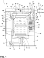
- FIG. 1 is a schematic cross-sectional view of an exemplary household appliance 1.
- the exemplary household appliance 1 is shown as a horizontal axis, front-load combination washing and drying machine 10 though this need not be the case.
- the household appliance 1 can be any household appliance, including a horizontal-axis or vertical-axis clothes washer, a combination washing machine and dryer, a clothes dryer, a tumbling or stationary refreshing/revitalizing machine, an extractor, a non-aqueous washing apparatus, a dishwasher, a refrigerator or freezer, or the like, in some non-limiting examples.
- the combination washing and drying machine 10 can include a structural support system including a cabinet or chassis 12.
- the chassis 12 can include a housing defining an interior 13.
- the chassis 12 can enclose components typically found in a conventional washing machine, such as motors, pumps, fluid lines, controls, sensors, transducers, and the like. Such components will not be described further herein except as necessary for a complete understanding of the present disclosure.
- the chassis 12 can define a housing within which a laundry holding system resides.
- a laundry holding system can include a tub 14 dynamically suspended within the structural support system of the chassis 12 by a suitable suspension system 28 and a drum 16 provided within the tub 14.
- the tub 14 can define at least a portion of a treating chamber 18.
- the treating chamber 18 can be located within the drum 16.
- the treating chamber 18 can have an access opening 19.
- the drum 16 can be configured to receive a laundry load through the access opening 19 with articles for treatment, including, but not limited to, a hat, a scarf, a glove, a sweater, a blouse, a shirt, a pair of shorts, a dress, a sock, and a pair of pants, a shoe, an undergarment, and a jacket.
- the drum 16 can include a plurality of perforations 20 such that liquid can flow between the tub 14 and the drum 16 through the perforations 20. It is also within the scope of the present disclosure for the laundry holding system to include only one receptacle with the receptacle defining the laundry treating chamber for receiving the load to be treated. At least one lifter 22 can extend from a wall of the drum 16 to lift the laundry load received in the treating chamber 18 while the drum 16 rotates.
- the laundry holding system can further include a closure 24 which can be movably mounted to the chassis 12 to selectively close both the tub 14 and the drum 16.
- the closure 24 is in the form of a door assembly 25 positioned on the front of the chassis 12.
- the closure 24 or door assembly 25 can include a lid, panel, viewing window, or the like.
- a bellows 26 can couple an open face of the tub 14 with the chassis 12, with the closure 24 sealing against the bellows 26 when the closure 24 is in the closed position.
- the combination washing and drying machine 10 can further include a washing circuit 30 having at least one wash circuit component 32 located within the chassis 12.
- the at least one wash circuit component 32 can include a liquid supply system for supplying water to the combination washing and drying machine 10 for use in treating laundry during a cycle of operation.
- the liquid supply system can include a source of water, such as a household water supply 40, which can include separate valves 42 and 44 for controlling the flow of hot and cold water, respectively.
- Water can be supplied through an inlet conduit 46 directly to the tub 14 or the drum 16 by controlling first and second diverter mechanisms 48 and 50, respectively.
- the diverter mechanisms 48, 50 can be a diverter valve having two outlets such that the diverter mechanisms 48, 50 can selectively direct a flow of liquid to one or both of two flow paths.
- Water from the household water supply 40 can flow through the inlet conduit 46 to the first diverter mechanism 48 which can direct the flow of liquid to a supply conduit 52.
- the second diverter mechanism 50 on the supply conduit 52 can direct the flow of liquid to a tub outlet conduit 54 which can be provided with a spray nozzle 56 configured to spray the flow of liquid 58 into the tub 14.
- water from the household water supply 40 can be supplied directly to the tub 14. While the valves 42, 44 and the inlet conduit 46 are illustrated exteriorly of the chassis 12, it will be understood that these components can be internal to the chassis 12.
- the combination washing and drying machine 10 can also be provided with a dispensing system for dispensing treating chemistry to the treating chamber 18 for use in treating the load of laundry according to a cycle of operation.
- the dispensing system can include a treating chemistry dispenser 62 which can be a single dose dispenser, a bulk dispenser, or an integrated single dose and bulk dispenser and is fluidly coupled to the treating chamber 18.
- the treating chemistry dispenser 62 can be configured to dispense a treating chemistry directly to the tub 14 or mixed with water from the liquid supply system through a dispensing outlet conduit 64.
- the dispensing outlet conduit 64 can include a dispensing nozzle 66 configured to dispense the treating chemistry into the tub 14 in a desired pattern and under a desired amount of pressure.
- the dispensing nozzle 66 can be configured to dispense a flow or stream of treating chemistry into the tub 14 by gravity, i.e. a non-pressurized stream.
- Water can be supplied to the treating chemistry dispenser 62 from the supply conduit 52 by directing the diverter mechanism 50 to direct the flow of water to a dispensing supply conduit 68.
- the treating chemistry dispenser 62 can include multiple chambers or reservoirs for receiving doses of different treating chemistries.
- the treating chemistry dispenser 62 can be implemented as a dispensing drawer that is slidably received within the chassis 12, or within a separate dispenser housing which can be provided in the chassis 12.
- the treating chemistry dispenser 62 can be moveable between a fill position, where the treating chemistry dispenser 62 is exterior to the chassis 12 and can be filled with treating chemistry, and a dispense position, where the treating chemistry dispenser 62 are interior of the chassis 12.
- Non-limiting examples of treating chemistries that can be dispensed by the dispensing system during a cycle of operation include one or more of the following: water, enzymes, fragrances, stiffness/sizing agents, wrinkle releasers/reducers, softeners, antistatic or electrostatic agents, stain repellants, water repellants, energy reduction/extraction aids, antibacterial agents, medicinal agents, vitamins, moisturizers, shrinkage inhibitors, and color fidelity agents, and combinations thereof.
- the combination washing and drying machine 10 can also include a recirculation and drain system for recirculating liquid within the laundry holding system and draining liquid from the combination washing and drying machine 10.
- Liquid supplied to the tub 14 through tub outlet conduit 54 and/or the dispensing supply conduit 68 typically enters a space between the tub 14 and the drum 16 and can flow by gravity to a sump 70 formed in part by a lower portion of the tub 14.
- the sump 70 can also be formed by a sump conduit 72 that can fluidly couple the lower portion of the tub 14 to a pump 74.
- the pump 74 can direct liquid to a drain conduit 76, which can drain the liquid from the combination washing and drying machine 10, or to a recirculation conduit 78, which can terminate at a recirculation inlet 80.
- the recirculation inlet 80 can direct the liquid from the recirculation conduit 78 into the drum 16.
- the recirculation inlet 80 can introduce the liquid into the drum 16 in any suitable manner, such as by spraying, dripping, or providing a steady flow of liquid. In this manner, liquid provided to the tub 14, with or without treating chemistry can be recirculated into the treating chamber 18 for treating the load of laundry within.
- the liquid supply and/or recirculation and drain system can be provided with a heating system which can include one or more devices for heating laundry and/or liquid supplied to the tub 14, such as a steam generator 82, an inline heater 83 and/or a sump heater 84.
- a heating system which can include one or more devices for heating laundry and/or liquid supplied to the tub 14, such as a steam generator 82, an inline heater 83 and/or a sump heater 84.
- Liquid from the household water supply 40 can be provided to the steam generator 82 through the inlet conduit 46 by controlling the first diverter mechanism 48 to direct the flow of liquid to a steam supply conduit 86.
- Steam generated by the steam generator 82 can be supplied to the tub 14 through a steam outlet conduit 87.
- the steam generator 82 can be any suitable type of steam generator such as a flow through steam generator or a tank-type steam generator.
- the sump heater 84 can be used to generate steam in place of or in addition to the steam generator 82.
- the steam generator 82 and/or sump heater 84 can be used to heat the laundry and/or liquid within the tub 14 as part of a cycle of operation.
- the illustrated suspension system, liquid supply system, recirculation and drain system, and dispensing system are shown for exemplary purposes only and are not limited to the systems shown in the drawings and described above.
- the liquid supply, dispensing, and recirculation and pump systems can differ from the configuration shown in FIG. 1 , such as by inclusion of other valves, conduits, treating chemistry dispensers, sensors, such as water level sensors and temperature sensors, and the like, to control the flow of liquid through the combination washing and drying machine 10 and for the introduction of more than one type of treating chemistry.
- the liquid supply system can include a single valve for controlling the flow of water from the household water source.
- the recirculation and pump system can include two separate pumps for recirculation and draining, instead of the single pump as previously described.
- the combination washing and drying machine 10 can also include a drive system for rotating the drum 16 within the tub 14.
- the drive system can include a motor 88, which can be directly coupled with the drum 16 through a drive shaft 90 to rotate the drum 16 about a rotational axis during a cycle of operation.
- the motor 88 can be a brushless permanent magnet (BPM) motor having a stator 92 and a rotor 94.
- BPM brushless permanent magnet
- the motor 88 can be coupled to the drum 16 through a belt and a drive shaft to rotate the drum 16, as is known in the art.
- Other motors such as an induction motor or a permanent split capacitor (PSC) motor, can also be used.
- the motor 88 can rotate the drum 16 at various speeds in either rotational direction.
- the motor 88 can rotate the drum 16 at various speeds in opposite rotational directions.
- the motor 88 can rotate the drum 16 at tumbling speeds wherein the fabric items in the drum 16 rotate with the drum 16 from a lowest location of the drum 16 towards a highest location of the drum 16, but fall back to the lowest location of the drum 16 before reaching the highest location of the drum 16.
- the rotation of the fabric items with the drum 16 can be facilitated by the at least one lifter 22.
- the force applied to the fabric items at the tumbling speeds is less than about 1G.
- the motor 88 can rotate the drum 16 at spin speeds wherein the fabric items rotate with the drum 16 without falling.
- the spin speeds can also be referred to as satellizing speeds or sticking speeds.
- the force applied to the fabric items at the spin speeds is greater than or about equal to 1G.
- tumble speed refers to rotating the drum at a tumble speed
- spinning refers to rotating the drum 16 at a spin speed
- rotating refers to rotating the drum 16 at any speed.
- the combination washing and drying machine 10 can also include a drying circuit 96.
- the drying circuit 96 can include a closed-loop or an open-loop circuit.
- the drying circuit 96 can have at least one drying circuit component 97 located within the chassis 12.
- the at least one drying circuit component 97 can include an air recirculation conduit that is fluidly coupled to and recirculates air 104 through the treating chamber 18.
- the air recirculation conduit can include a blower 98 and a heating element 102.
- a condenser 100 can also be provided. In such a case, the condenser 100 can be provided with a condenser drain conduit (not shown in FIG. 1 ) that fluidly couples the condenser 100 with the pump 74 and the drain conduit 76.
- Condensed liquid collected within the condenser 100 can flow through the condenser drain conduit to the pump 74, where it can be provided to the recirculation and drain system.
- the drying circuit 96 is shown adjacent an upper portion of the tub 14, it will be understood that the disclosure is not so limited and the drying circuit 96 can be provided at any suitable location within the chassis 12.
- the drying circuit 96 can provide drying air 104 into the treating chamber 18 via the perforations 20 for drying the laundry items.
- an open loop circuit can be implemented where air is heated by the heating element 102, passed through the drum 16, and exhausted out of the combination washing and drying machine 10.
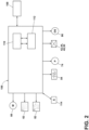
- the combination washing and drying machine 10 can also include a control system for controlling the operation of the combination washing and drying machine 10 to implement one or more cycles of operation.
- the control system can include a controller 106 located within the chassis 12 and a user interface 108 that is operably coupled with the controller 106.
- the user interface 108 can include one or more knobs, dials, switches, displays, touch screens and the like for communicating with the user, such as to receive input and provide output.
- the user can enter different types of information including, without limitation, cycle selection and cycle parameters, such as cycle options.
- the controller 106 can include the machine controller and any additional controllers provided for controlling any of the components of the washing machine 10.
- the controller 106 can include the machine controller and a motor controller.
- Many known types of controllers can be used for the controller 106.
- the controller is a microprocessor-based controller that implements control software and sends/receives one or more electrical signals to/from each of the various working components to effect the control software.
- proportional control (P), proportional integral control (PI), and proportional derivative control (PD), or a combination thereof, a proportional integral derivative control (PID control) can be used to control the various components.
- the controller 106 can be provided with a memory 110 and a central processing unit (CPU) 112.
- the memory 110 can be used for storing the control software that is executed by the CPU 112 in completing a cycle of operation using the combination washing and drying machine 10 and any additional software. Examples, without limitation, of cycles of operation include: wash, heavy duty wash, delicate wash, quick wash, pre-wash, refresh, rinse only, and timed wash.
- the memory 110 can also be used to store information, such as a database or table, and to store data received from one or more components of the combination washing and drying machine 10 that can be communicably coupled with the controller 106.
- the database or table can be used to store the various operating parameters for the one or more cycles of operation, including factory default values for the operating parameters and any adjustments to them by the control system or by user input.
- the controller 106 can be operably coupled with one or more components of the combination washing and drying machine 10 for communicating with and controlling the operation of the component to complete a cycle of operation.
- the controller 106 can be operably coupled with the motor 88, the pump 74, the treating chemistry dispenser 62, the steam generator 82, the sump heater 84, and the drying circuit 96 to control the operation of these and other components to implement one or more of the cycles of operation.
- the controller 106 can also be coupled with one or more sensors 114 provided in one or more of the systems of the washing machine 10 to receive input from the sensors, which are known in the art and illustrated in FIG. 1 in a lower portion of the treating chamber 18 for exemplary purposes only.
- sensors 114 that can be communicably coupled with the controller 106 include: a treating chamber temperature sensor, a moisture sensor, a weight sensor, a chemical sensor, a position sensor and a motor torque sensor, which can be used to determine a variety of system and laundry characteristics, such as laundry load inertia or mass.
- the chassis 12 can define an open face 15 as shown.
- the open face 15 is at least partially formed by the bellows 26 and the tub 14, though this need not be the case.
- the door assembly 25 can include a door 120, which can be a functional door, selectively closing the open face 15.
- a hinge 130 can be mounted to the door 120.
- the hinge 130 can include a hinge pin 131 and a hinge plate 132, with the hinge plate 132 rotatable about the hinge pin 131.
- the hinge plate 132 can be mounted to the door 120 such that the door 120 co-rotates with the hinge plate 132.
- the hinge 130 can also define a first rotation axis 135 as shown.
- the first rotation axis 135 is illustrated extending through the hinge pin 131.
- the door can be rotatable about the first rotation axis 135 such that the door 120 is movable between an open and closed position.
- the door 120 can close the open face 15 when in the closed position.
- the door assembly 25 can also include an outer door 140, which can be an aesthetic door, and an outer hinge 141 mounted thereto.
- the outer door 140 can be positioned exteriorly of the door 120 with respect to the open face 15.
- the outer hinge 141 can be spaced from the hinge 130 and define an outer rotation axis 145. In the illustrated example, the outer door 140 is in a fully-open position.
- the outer door 140 and the door 120 can each freely rotate about the respective outer rotation axis 145 and first rotation axis 135.
- the door 120 can close the open face 15 adjacent the bellows 26, and the outer door 140 can close over the door 120 to form an exterior surface of the household appliance 1 ( FIG. 1 ).
- the outer door 140 and the door 120 can be selectively coupled together such that they co-rotate at least about the respective outer rotation axis 145 and first rotation axis 135.
- An actuator assembly 150 can be provided for movement of the door 120.
- the actuator assembly 150 can include a first actuator 151 and a second actuator 152. Either or both of the first actuator 151 or the second actuator 152 can be operably coupled to the hinge 130. In the example shown, the second actuator 152 is directly coupled to the hinge 130 though this need not be the case.
- a linkage 134 can be coupled to the hinge plate 132. The first actuator 151 can be coupled to the linkage 134. In this manner, the first actuator can be indirectly coupled to the hinge 130 by way of the linkage 134.
- a hinge block 160 can be provided in the door assembly 25.
- the hinge block 160 can be positioned within or coupled to the chassis 12.
- the actuator assembly 150 can be mounted to the hinge block 160 as shown.
- the first actuator 151 is arranged in parallel with the second actuator 152. It is understood that the first and second actuators 151, 152 can have any suitable arrangement.
- the door assembly 25 is movable between a closed position, in which the door 120 closes the open face 15, and a fully-open position, in which the door 120 forms a maximum opening angle with the open face 15 as will be described below. It can be appreciated that when the outer door 140 and the door 120 are each in a fully-open position, the position of the fully-opened outer door 140 can limit a maximum opening angle of the door 120. For instance, if the door 120 were to be opened solely by rotation about the first rotation axis 135, the door 120 would contact a portion 146 of the outer door when fully opened.
- FIG. 4 a schematic view illustrates the door assembly 25 in a closed position.
- the door 120, the hinge 130 including the hinge pin 131 and hinge plate 132, the hinge block 160, and the actuator assembly 150 are illustrated in isolation from the chassis 12 ( FIG. 3 ) for visual clarity.
- the hinge block 160 and the door 120 are illustrated in dashed line for visual clarity.
- the hinge plate 132 is mounted to the door 120 such that the hinge plate 132 co-rotates with the door 120 about the hinge pin 131 and first rotation axis 135. In the example shown, with the hinge plate 132 and door 120 in the closed position, the door 120 closes the open face 15 ( FIG. 3 ).
- first actuator 151 and the second actuator 152 are in the form of a respective first hydraulic cylinder 171 and a second hydraulic cylinder 172 though this need not be the case.
- Any suitable actuator can be provided, including a pneumatic actuator, electric actuator, linear actuator, rotary actuator, or the like, or combinations thereof.
- the actuator assembly 150 can be coupled to the controller 106 ( FIG. 1 ) such that the controller 106 can controllably operate the first and second actuators 151, 152, including for individual actuation, simultaneous actuation, or the like.
- the first hydraulic cylinder 171 and the second hydraulic cylinder 172 can include a respective first cylinder 181 and second cylinder 182, as well as a respective first piston 191 and second piston 192.
- the first and second cylinders 181, 182 can be mounted within the hinge block 160. Either or both of the first cylinder 181 or the second cylinder 182 can be movable within the hinge block 160.
- the second cylinder 182 is fixedly mounted to the hinge block 160.
- a movable carrier plate 162 is provided within the hinge block 160 and coupled to the first cylinder 181.
- the carrier plate 162 and the first cylinder 181 can be movable within the hinge block 160 while the second cylinder 182 remains in place during rotation of the door 120.
- the first piston 191 can extend from the first cylinder 181 and couple to the hinge plate 132. More specifically, an arm 133 can extend from the hinge plate 132, and the linkage 134 can be coupled between the first piston 191 and the arm 133 as shown.
- the second piston 192 can extend from the second cylinder 182 and be coupled to the hinge pin 131.
- the second piston 192 includes a sleeve 194 that at least partially surrounds the hinge pin 131, wherein the hinge pin 131 can rotate within the sleeve 194.
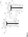
- FIG. 5 illustrates the actuator assembly 150 with the first and second hydraulic cylinders 171, 172 in an exemplary arrangement. It is contemplated that the first and second hydraulic cylinders 171, 172 can be fluidly coupled such that actuation of the first hydraulic cylinder 171 generates a corresponding actuation of the second hydraulic cylinder 172.
- An inlet 183 and an outlet 184 are provided with the first cylinder 181.
- An inlet 185 and an outlet 186 are provided with the second cylinder 182.
- a first fluid path 187 extends between the outlet 186 of the second cylinder 182 and the inlet 183 of the first cylinder 181.
- a second fluid path 188 extends between the outlet 184 of the first cylinder 181 and the inlet 185 of the second cylinder 182.
- the first hydraulic cylinder 171 and the second hydraulic cylinder 172 can define a respective first diameter D1 and second diameter D2, as well as a respective first length L1 and second length L2.
- a first stroke length S1 and a second stroke length S2 can also be defined for the respective first and second hydraulic cylinders 171, 172.
- a "stroke length" of a hydraulic cylinder will refer to a maximum distance traveled by a piston of the hydraulic cylinder between a fully-retracted position to a fully-extended position of that piston.
- the first stroke length S1 can be 35 mm and the second stroke length S2 can be 40 mm.
- the first stroke length S1 or second stroke length S2 can be in a range between 10-200 mm.
- the first stroke length S1 can be between 0.1-10 times the second stroke length S2.
- a length-to-diameter ratio of each hydraulic cylinder 171, 172 can be selected, modified, or the like to provide a desired stroke length for each piston 191, 192.
- the first length L1 can be between 0.1-10 times the first diameter D1.
- the second length L2 can be between 0.1-10 times the second diameter D2. It can be appreciated that the length-to-diameter ratios L1/D1 and L2/D2 for the respective first and second hydraulic cylinders 171, 172 can be selected to form a predetermined ratio of the stroke lengths S1/S2.
- first and second hydraulic cylinders 171, 172 can be double-acting hydraulic cylinders configured to extend or retract during operation.
- the door assembly 25 is shown in an intermediate position with the door 120 partially opened.
- the actuator assembly 150 can exert multiple forces upon the hinge 130 such that the hinge 130 can move along multiple motion paths.
- the hinge 130 can move along multiple motion paths simultaneously to form a combined or net motion path.
- the hinge 130 can sequentially move along multiple motion paths.
- opening of the door 120 causes the carrier plate 162 and second actuator 151 to shift outwardly and at least partially out of the hinge block 160.
- the first actuator 151 can remain in place within the hinge block 160.
- opening of the door 120 causes the first piston 191 to move out of the first cylinder 181 by way of the linkage 134.
- Such motion of the first piston 191 causes rotation of the hinge plate 132 about the first rotation axis 135, defining a first motion path P1.
- the hinge plate 132 and the door 120 can co-rotate such that the door 120 is also rotated along the first motion path P1.
- the first motion path P1 can form a rotational motion path to rotate the door 120 about the first rotation axis 135.
- An opening angle 128 can also be defined for the door 120 along the first motion path P1.
- the opening angle 128 at any position of the door 120 can be defined with respect to the closed position ( FIG. 4 ) of the door 120.
- the opening angle 128 can be between 0-180°, including between 0-160°, including between 0-150°, including between 0-135°, in some non-limiting examples.
- Motion of the first piston 191 also generates corresponding motion of the second piston 192 out of the second cylinder 182 by way of the fluid coupling between the first and second cylinders 181, 182 as described above.
- the sleeve 194 causes the hinge pin 131 to move along a second motion path P2.
- the second motion path P2 forms a translational motion path along a linear direction.
- the second motion path P2 is perpendicular to the open face 15 in the example shown. It is understood that the hinge pin 131 and the door 120 can move together along the second motion path P2. In this manner, the hinge 130 can be movable along the second motion path P2 when the door 120 is rotated about the first rotation axis 135.
- FIG. 7 illustrates the door assembly 25 in the fully-open position.
- the carrier plate 162 can form a maximum-shifted position outside of the hinge block 160
- the first piston 191 can form a fully-extended position from the first cylinder 181
- the second piston 192 can form a fully-extended position from the second cylinder 182.
- the first actuator 151 can be operable between a first position, e.g. the retracted position as shown in FIG. 4 , and a second position, e.g. the fully-extended position shown in FIG. 7 , to rotate the door 120 about the first rotation axis 135.
- the second actuator 152 can be operable between a non-translated position, e.g. the retracted position shown in FIG. 4 , and a translated position, e.g. the fully-extended position shown in FIG. 7 .
- the hinge 130 In the translated position, the hinge 130 can be translated away from the chassis 12 ( FIG. 3 ).
- the actuator assembly 150 can define a rotational motion path (e.g.
- the first actuator 171 acting upon the hinge plate 132 can form the first motion path P1
- the second actuator 172 acting upon the hinge pin 131 can form the second motion path P2 as shown.
- the door 120 and hinge 130 can be shifted with respect to the outer door 140 ( FIG. 3 ), and away from the chassis 12 ( FIG. 3 ), providing for a wider opening angle and improved access to the interior.
- the door 120 and hinge 130 can be shifted in a combined motion path that includes movement directly away from the chassis 12 and also a lateral shift along the chassis 12 ( FIG. 3 ), to provide for wider opening angles and avoid impingement with the outer door 140 ( FIG. 3 ).
- FIG. 8 illustrates a perspective view of the door assembly 25 in the intermediate position shown in FIG. 6 .
- the door 120 is not illustrated.
- the hinge block 160 can include a movable arm 163 and a pair of guide slots 164.
- the carrier plate 162 can be coupled to the movable arm 163 for motion with respect to the hinge block 160. Rotation of the hinge plate 132 can cause actuation of the first hydraulic cylinder 171 and corresponding sliding of the movable arm 163 and carrier plate 162 along the guide slots 164.
- the sleeve 194 can be coupled to a center of the hinge pin 131 as shown. Motion of the second hydraulic cylinder 172 can exert a non-rotational force on the center of the hinge pin 131 to shift the hinge 130 in a linear direction along the second motion path P2.
- FIG. 9 illustrates a perspective view of the door assembly 25 in the fully-open position shown in FIG. 7 , with the door 120 removed for clarity.
- a mounting arm 165 is shown within the hinge block 160.
- the first hydraulic cylinder 171 can be coupled to the mounting arm 165 as shown.
- the carrier plate 162 and second hydraulic cylinder 172 can slide with the movable arm 163, while the first hydraulic cylinder 171 remains in a fixed position on the mounting arm 165.
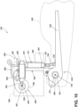
- FIG. 10 another door assembly 125 is shown that can be utilized in the household appliance 1, including the combination washing and drying machine 10 ( FIG. 1 ).
- the door assembly 125 is similar to the door assembly 25; therefore, like parts will be identified with like numerals increased by 100, with it being understood that the description of the like parts of the door assembly 25 applies to the door assembly 125, except where noted.
- the door assembly 125 includes a door 220, a hinge 230, a hinge pin 231, a hinge plate 232 with an arm 233, a linkage 234, a hinge block 260, a carrier plate 262, and an actuator assembly 250.
- the door assembly 125 is illustrated in isolation from the chassis 12 ( FIG. 3 ) for visual clarity.
- the hinge block 260 and the door 220 are illustrated in dashed line for visual clarity.
- the actuator assembly 250 can include a first actuator 251 and a second actuator 252. Either or both of the first actuator 251 or the second actuator 252 can be movable within the hinge block 260.
- One difference compared to the door assembly 25 is that the first and second actuators 251, 252 can be arranged perpendicular to one another.
- the first actuator 251 is coupled to the carrier plate 262 and the second actuator 252 is mounted to the hinge block 260 in a fixed position and perpendicular to the first actuator 271.
- the first actuator 251 and the second actuator 252 are in the form of a first hydraulic cylinder 271 and a second hydraulic cylinder 272 though this need not be the case.
- Any suitable actuator can be provided, including a pneumatic actuator, electric actuator, linear actuator, rotary actuator, or the like, or combinations thereof.
- the actuator assembly 250 can be coupled to the controller 106 ( FIG. 1 ) such that the controller 106 can controllably operate the first and second actuators 251, 252, including for individual actuation, simultaneous actuation, or the like.
- the first hydraulic cylinder 271 and the second hydraulic cylinder 272 can include a respective first cylinder 281 and second cylinder 282, as well as a respective first piston 291 and second piston 292.
- the first and second cylinders 281, 282 can be mounted within the hinge block 260.
- a first fluid path 287 and a second fluid path 288 can be provided for fluidly coupling the first hydraulic cylinder 271 and the second hydraulic cylinder 272.
- the second piston 292 extends out of a left-side portion of the second cylinder 282 as shown.
- an actuator lock 320 (illustrated in dashed line) can be provided with the hinge block 260.
- the actuator lock 320 can include a portion receiving the second piston 292 and preventing or blocking further extension of the second piston 292 toward the actuator lock 320.
- a rotatable linkage 300 can be provided in the door assembly 125.
- the rotatable linkage 300 can include a body 305 with a first end 301 and a second end 302 as shown.
- a first aperture 306 can be provided at the first end 301.
- a second aperture 307 can be provided at the second end 302. The first aperture 306 can receive the hinge pin 231.
- a second rotation axis 304 can be defined by the second aperture 307 as shown.
- the second aperture 307 can be mounted to the hinge block 260 ( FIG. 10 ) such that the rotatable linkage 300 can rotate about the second rotation axis 304 with respect to the hinge block 260.
- the rotatable linkage 300 can also be coupled to the carrier plate 262. Thus, rotation of the rotatable linkage 300 can cause corresponding rotation of the second hydraulic cylinder 272 by way of the carrier plate 262.
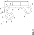
- FIG. 11 illustrates the rotatable linkage 300 and carrier plate 262 in isolation.
- the body 305 of the rotatable linkage 300 can have a generally C-shaped profile. More specifically, the body 305 can include a first portion 308, a second portion 309, and a curved portion 310 extending between the first and second portions 308, 309. The curved portion 310 can extend between a first end 311 and a second end 312 as shown.
- a first length L1 can be defined along the first portion 308 between the center of the first aperture 306 and the first end 311 of the curved portion 310.
- a second length L2 can be defined along the second portion 309 between the center of the second aperture 307 and the second end 312 of the curved portion 310.
- the first length L1 can be between 0.2-5 times the second length L2.
- the carrier plate 262 can be provided with the rotatable linkage 300.
- the carrier plate 262 can be a distinct component and mounted to the rotatable linkage 300 in some examples, or the carrier plate 262 can be unitarily formed with the rotatable linkage 300 in some examples.
- the carrier plate 262 can be coupled to the body 305 between the first end 301 and the second end 302 as shown.
- FIG. 12 the door assembly 125 is illustrated in an intermediate position with the door 220 partially opened.
- the rotatable linkage 300, carrier plate 262, and first cylinder 281 can remain stationary.
- the first piston 291 is moved to a maximally-extended position to form a first stroke length S1.
- the actuator lock 320 and the second piston 292 can also remain stationary between the closed position of FIG. 11 and the intermediate position of FIG. 12 .
- the actuator lock 320 can further include a body with a recess 322 receiving the second piston 292.
- the recess 322 can be formed to a predetermined depth, thereby limiting extension of the second piston 292 in a direction toward the actuator lock 320 as described above.
- Opening of the door 220 causes the first piston 291 to be drawn out of the first cylinder 281.
- the actuator assembly 250 can exert multiple forces upon the hinge 230 such that the hinge 230 can move along multiple motion paths.
- the hinge 230 can move along multiple motion paths simultaneously to form a combined or net motion path.
- the hinge 230 can sequentially move along multiple motion paths.
- the first hydraulic cylinder 271 can exert a force on the hinge plate 232 by way of the linkage 234 to form a first motion path P1 for the hinge 230. It is understood that the door 220 also travels along the first motion path P1 with the hinge plate 232. Thus, the first motion path P1 can be a rotational motion path to rotate the door 120 about the first rotation axis 235.
- FIG. 13 a fully-open position of the door assembly 125 is shown. In this position, the first piston 291 remains fully extended from the first cylinder 281.
- the rotatable linkage 300 has been rotated about the second rotation axis 304, along with the carrier plate 262, first cylinder 281, and first piston 291.
- Rotation of the rotatable linkage 300 can cause the second piston 292 to move out of the actuator lock 320 as shown.
- the actuator lock 320 can rotate with the rotatable linkage 300 such that the recess 322 is unaligned with the second piston 292. It is understood that closing of the door can provide for re-alignment and engagement of the recess 322 with the second piston 292.
- the hinge 230 including the hinge pin 231 and hinge plate 232, is also rotated about the second rotation axis 304 to define a second motion path P2 as shown.
- An overall motion path P3 is illustrated for the door assembly 125 which combines the first motion path P1 ( FIG. 12 ) and the second motion path P2. It can be seen that the overall motion path P3 provides at least lateral motion M (indicated with an arrow) for the door 220 and hinge 230, such that the hinge 230 can be shifted laterally along the chassis 12 ( FIG. 3 ) when the door 220 is opened.
- the actuator assembly 250 can provide sequential motion paths for the door 220 and hinge 230, whereby the first motion path P1 is followed by the second motion path P2 to form the overall motion path P3.
- the first actuator 251 can be operable between a first position, e.g. the retracted position as shown in FIG. 10 , and a second position, e.g. the fully-extended position shown in FIG. 13 , to rotate the door 220 about the first rotation axis 235.
- the second actuator 152 can be operable between a non-translated position, e.g. the retracted position shown in FIG. 10 , and a translated position, e.g. the fully-extended position shown in FIG. 13 .
- the hinge 230 can be translated at least laterally along the chassis 12 ( FIG. 3 ).
- the door 220 and hinge 230 can be shifted with respect to the outer door 140 ( FIG. 3 ), and at least laterally along the chassis 12 ( FIG. 3 ), providing for a wider opening angle and improved access to the interior.
- the door 220 and hinge 230 can be shifted in a combined motion path that includes movement directly away from the chassis 12 and also a lateral shift along the chassis 12 ( FIG. 3 ), to provide for wider opening angles and avoid impingement with the outer door 140 ( FIG. 3 ).
- FIG. 14 illustrates the actuator assembly 250 with the first and second hydraulic cylinders 271, 272 in the perpendicular arrangement as shown in FIGS. 10-13 . It is contemplated that the first and second hydraulic cylinders 271, 272 can be fluidly coupled such that actuation of the first hydraulic cylinder 271 generates a corresponding actuation of the second hydraulic cylinder 272.
- An inlet 283 and an outlet 284 are provided with the first cylinder 181.
- An inlet 285 and an outlet 286 are provided with the second cylinder 182.
- the first fluid path 287 (illustrated in solid line) extends between the outlet 286 of the second cylinder 282 and the inlet 283 of the first cylinder 281.
- the second fluid path 288 (illustrated in dashed line) extends between the outlet 284 of the first cylinder 281 and the inlet 285 of the second cylinder 282.
- first hydraulic cylinder 271 can form a "leader" cylinder and the second hydraulic cylinder 272 can form a "follower” cylinder.
- the second piston 292 can be configured to extend or retract out of both sides of the second cylinder 282. For example, when the first piston 291 is fully retracted, the second piston 292 can extend from the left side of the second cylinder 282 (see FIG. 10 ). As the first piston 291 is pulled outward, the second piston 292 can move to the right and extend out of the right side of the second cylinder 282 (see FIG. 13 ).
- the described aspects of the present disclosure provide for a variety of benefits.
- the actuator assembly exerting multiple forces on multiple portions of the hinge or the door provides for a combined motion path, including a rotational component and a translational component, that increases a maximum opening angle of the door for improved access.
- the leader/follower cylinder arrangement provides for a smooth, assisted opening action wherein user rotation of the door generates automatic translational movement from the actuator assembly.
- the disclosed actuator assembly can shift the inner door hinge away from the outer door such that the inner door has a wider range of motion compared to traditional paired-door assemblies.
- the disclosed actuator assembly can also shift the inner door hinge back into the chassis as the door is closed, providing for an improved aesthetic appearance with the outer door fully hiding or overlying the inner door when closed.
- the disclosed actuator lock can provide for a limit on actuator travel once the door is closed, leading to improved stability in the door assembly.
- the relative size or dimensions of the actuators e.g. the length-to-diameter ratio of the hydraulic cylinders or a ratio of stroke lengths, can be selected to accommodate a variety of outer-door hinge dimensions when shifting the inner door hinge, e.g. larger or smaller lateral motion as the door is opened, which provides a simplified hinge assembly across multiple appliances.
- the different features and structures of the various aspects can be used in combination with each other as desired, or can be used separately. That one feature can not be illustrated in all of the aspects is not meant to be construed that it cannot be, but is done for brevity of description. Thus, the various features of the different aspects can be mixed and matched as desired to form new aspects, whether or not the new aspects are expressly described.
Landscapes
- Engineering & Computer Science (AREA)
- Textile Engineering (AREA)
- Main Body Construction Of Washing Machines And Laundry Dryers (AREA)
Abstract
A door assembly (25; 125) for a laundry treating appliance includes a door (120; 220) selectively closing an open face (15) or an aperture defined by the chassis of the laundry treating appliance. A hinge (130; 230) is mounted to the door (120; 220) and defines a rotation axis. A first actuator (151; 251) is operably coupled to the hinge (130; 230) and defines a rotational motion path to rotate the door (120; 220) about the rotation axis. A second actuator (152; 252) is operably coupled to the hinge (130; 230) and defines a translational motion path.
Description
- Household appliances, including laundry treating appliances such as washing machines, combination washer/dryers, refreshers, and non-aqueous systems, can have a configuration based on a treating chamber in which items are placed for treating. The laundry treating appliance can have a controller that implements a number of user-selectable, pre-programmed cycles of operation having one or more operating parameters. Hot water, cold water, or a mixture thereof, along with various treating chemistries, can be supplied to the treating chamber in accordance with the cycle of operation. In addition, hot air, cold air, or a mixture thereof can be supplied to the treating chamber in accordance with the cycle of operation and via an air flow assembly.
- In some exemplary implementations, household appliances can include an inner door selectively providing access to an interior space, and an outer aesthetic door covering the inner door. Such appliances can include one or more hinges for opening the outer and inner doors.
- In one aspect, the disclosure relates to a door assembly for closing an open face defined by a chassis. The door assembly includes a door selectively closing the open face, a hinge mounted to the door and defining a first rotation axis, a first actuator operably coupled to the hinge and defining a rotational motion path to rotate the door about the first rotation axis; and a second actuator operably coupled to the hinge and defining a translational motion path, wherein the hinge is movable along the translational motion path when the door is rotated about the first rotation axis.
- In another aspect, the disclosure relates to a household appliance. The household appliance includes a chassis defining an interior with an open face, and a door assembly coupled to the chassis and including a door movable between open and closed positions, with the door closing the open face when in the closed position, a first rotation axis defined along the door, and an actuator assembly operably coupled to the door, the actuator assembly defining a rotational motion path to rotate the door about the first rotation axis, and also defining a translational motion path to shift the rotational motion path in at least a linear direction.
- In yet another aspect, the disclosure relates to a household appliance. The household appliance includes a chassis defining an interior with an open face, a door selectively closing the open face, a hinge mounted to the door and defining a rotation axis, a first actuator operably coupled to the hinge and operable between first and second positions to rotate the door about the rotation axis, and a second actuator operably coupled to the hinge and operable between non-translated and translated positions, where, in the translated position, the hinge is translated at least one of laterally or away from the chassis.
- In the drawings:
-
FIG. 1 is a schematic cross-sectional view of an exemplary household appliance in the form of a laundry treating appliance in accordance with various aspects described herein. -
FIG. 2 is a schematic diagram of a control system of the laundry treating appliance ofFIG. 1 . -
FIG. 3 is a top cross-sectional view of the laundry treating appliance ofFIG. 1 illustrating a door assembly in accordance with various aspects described herein. -
FIG. 4 is a schematic top view of the door assembly ofFIG. 3 in a closed position. -
FIG. 5 is a schematic diagram of an actuator assembly in the door assembly ofFIG. 3 in accordance with various aspects described herein. -
FIG. 6 is a schematic top view of the door assembly ofFIG. 3 in an intermediate position. -
FIG. 7 is a schematic top view of the door assembly ofFIG. 3 in a fully-open position. -
FIG. 8 is a perspective view of the door assembly ofFIG. 3 in the intermediate position ofFIG. 5 . -
FIG. 9 is a perspective view of the door assembly ofFIG. 3 in the fully-open position ofFIG. 7 . -
FIG. 10 is a schematic top view of another door assembly that can be utilized with the household appliance ofFIG. 1 in accordance with various aspects described herein, and in a closed position. -
FIG. 11 is a schematic view of a rotatable linkage in the door assembly ofFIG. 10 . -
FIG. 12 is a schematic top view of the door assembly ofFIG. 10 in an intermediate position. -
FIG. 13 is a schematic top view of the door assembly ofFIG. 10 in a fully-open position. -
FIG. 14 is a schematic diagram of an actuator assembly in the door assembly ofFIG. 10 in accordance with various aspects described herein. - Aspects of the present disclosure generally relate to a door assembly. In some implementations, household appliances, cabinets, or the like can include an overlapping-door arrangement wherein an inner "functional" door closes an interior space, and an outer "aesthetic" door overlies the inner door to form an exterior surface of the appliance or cabinet. Use of an outer door can provide a customizable aesthetic appearance, for example, where the inner door can include other functional elements such as a projecting handle, sealing components, or the like. Access to the interior space in such appliances can involve first opening the outer/aesthetic door and then opening the inner door. For aesthetic purposes, the hinges of each door should be closely spaced together or co-arranged on a common hinge such that little to no gap exists between the doors and surrounding frame when closed. However, a maximum opening angle of the inner door can be undesirably limited, for example due to "pinch points" where the outer door abuts the inner door when both are fully opened.
- Aspects of the disclosure provide for a door assembly with a movable hinge, such that the inner door can shift or move along at least one motion path during opening and closing. The described aspects provide for an improved maximum opening angle, in one example providing nearly 30% more range of motion in opening angle compared to a traditional dual-door arrangement, while preserving a desired aesthetic appearance and minimal gaps with the cabinet when both doors are closed. In one example, an actuator assembly can provide multiple motion paths to shift the inner door and hinge away from the cabinet during opening. In another example, an actuator assembly can provide multiple motion paths to shift the inner door and hinge at least laterally along the cabinet during opening.
- For the purposes of illustration, the present disclosure will be described in terms of a household appliance such as a combination laundry washer/dryer. It is understood that the disclosure is not so limited, and aspects described herein have general applicability in a variety of door assemblies and household appliances including, but not limited to, free-standing cabinets, laundry treating appliances, dishwashers, refrigerators, freezers, or the like. Some non-limiting examples of laundry treating appliances include laundry washing appliances, laundry drying appliances, combination laundry washer/dryers, refreshing/revitalizing machines, extractors, non-aqueous washing apparatuses, or the like.
- Washing machines are typically categorized as either a vertical axis washing machine or a horizontal axis washing machine. The terms "vertical axis" and "horizontal axis" are often used as shorthand terms for the manner in which the appliance imparts mechanical energy to the load of laundry, even when the relevant rotational axis is not absolutely vertical or horizontal. As used herein, the "vertical axis" washing machine refers to a washing machine having a rotatable drum, perforate or imperforate, that holds fabric items and a clothes mover, such as an agitator, impeller, nutator, and the like within the drum. The clothes mover moves within the drum to impart mechanical energy directly to the clothes or indirectly through wash liquid in the drum. The clothes mover can typically be moved in a reciprocating rotational movement. In some vertical axis washing machines, the drum rotates about a vertical axis generally perpendicular to a surface that supports the washing machine. However, the rotational axis need not be vertical. The drum can rotate about an axis inclined relative to the vertical axis.
- As used herein, the "horizontal axis" washing machine refers to a washing machine having a rotatable drum, perforated or imperforate, that holds laundry items and washes the laundry items. In some horizontal axis washing machines, the drum rotates about a horizontal axis generally parallel to a surface that supports the washing machine. However, the rotational axis need not be horizontal. The drum can rotate about an axis inclined or declined relative to the horizontal axis. In horizontal axis washing machines, the clothes are lifted by the rotating drum and then fall in response to gravity to form a tumbling action. Mechanical energy is imparted to the clothes by the tumbling action formed by the repeated lifting and dropping of the clothes. Vertical axis and horizontal axis machines are best differentiated by the manner in which they impart mechanical energy to the fabric articles.
- Regardless of the axis of rotation, a washing machine can be top-loading or front-loading. In a top-loading washing machine, laundry items are placed into the drum through an access opening in the top of a cabinet, while in a front-loading washing machine laundry items are placed into the drum through an access opening in the front of a cabinet. If a washing machine is a top-loading horizontal axis washing machine or a front-loading vertical axis washing machine, an additional access opening is located on the drum.
- All directional references (e.g., radial, axial, proximal, distal, upper, lower, upward, downward, left, right, lateral, front, back, top, bottom, above, below, vertical, horizontal, clockwise, counterclockwise, upstream, downstream, forward, aft, etc.) are only used for identification purposes to aid the reader's understanding of the present disclosure, and do not create limitations, particularly as to the position, orientation, or use of the disclosure. Connection references (e.g., attached, coupled, connected, or joined) are to be construed broadly and can include intermediate members between a collection of elements and relative movement between elements unless otherwise indicated. As such, connection references do not necessarily infer that two elements are directly connected and in fixed relation to one another. Furthermore, as used herein, the term "set" or a "set" of elements can be any number of elements, including only one. The exemplary drawings are for purposes of illustration only and the dimensions, positions, order and relative sizes reflected in the drawings attached hereto can vary.
-
FIG. 1 is a schematic cross-sectional view of anexemplary household appliance 1. In the illustrated example, theexemplary household appliance 1 is shown as a horizontal axis, front-load combination washing and dryingmachine 10 though this need not be the case. Thehousehold appliance 1 can be any household appliance, including a horizontal-axis or vertical-axis clothes washer, a combination washing machine and dryer, a clothes dryer, a tumbling or stationary refreshing/revitalizing machine, an extractor, a non-aqueous washing apparatus, a dishwasher, a refrigerator or freezer, or the like, in some non-limiting examples. - The combination washing and drying
machine 10 can include a structural support system including a cabinet orchassis 12. Thechassis 12 can include a housing defining an interior 13. Thechassis 12 can enclose components typically found in a conventional washing machine, such as motors, pumps, fluid lines, controls, sensors, transducers, and the like. Such components will not be described further herein except as necessary for a complete understanding of the present disclosure. - The
chassis 12 can define a housing within which a laundry holding system resides. Such a laundry holding system can include atub 14 dynamically suspended within the structural support system of thechassis 12 by asuitable suspension system 28 and adrum 16 provided within thetub 14. Thetub 14 can define at least a portion of a treatingchamber 18. For example, the treatingchamber 18 can be located within thedrum 16. The treatingchamber 18 can have anaccess opening 19. Thedrum 16 can be configured to receive a laundry load through the access opening 19 with articles for treatment, including, but not limited to, a hat, a scarf, a glove, a sweater, a blouse, a shirt, a pair of shorts, a dress, a sock, and a pair of pants, a shoe, an undergarment, and a jacket. Thedrum 16 can include a plurality ofperforations 20 such that liquid can flow between thetub 14 and thedrum 16 through theperforations 20. It is also within the scope of the present disclosure for the laundry holding system to include only one receptacle with the receptacle defining the laundry treating chamber for receiving the load to be treated. At least onelifter 22 can extend from a wall of thedrum 16 to lift the laundry load received in the treatingchamber 18 while thedrum 16 rotates. - The laundry holding system can further include a
closure 24 which can be movably mounted to thechassis 12 to selectively close both thetub 14 and thedrum 16. In the example shown, theclosure 24 is in the form of adoor assembly 25 positioned on the front of thechassis 12. In some examples, theclosure 24 ordoor assembly 25 can include a lid, panel, viewing window, or the like. A bellows 26 can couple an open face of thetub 14 with thechassis 12, with theclosure 24 sealing against thebellows 26 when theclosure 24 is in the closed position. - The combination washing and drying
machine 10 can further include awashing circuit 30 having at least onewash circuit component 32 located within thechassis 12. The at least onewash circuit component 32 can include a liquid supply system for supplying water to the combination washing and dryingmachine 10 for use in treating laundry during a cycle of operation. The liquid supply system can include a source of water, such as ahousehold water supply 40, which can includeseparate valves inlet conduit 46 directly to thetub 14 or thedrum 16 by controlling first andsecond diverter mechanisms diverter mechanisms diverter mechanisms household water supply 40 can flow through theinlet conduit 46 to thefirst diverter mechanism 48 which can direct the flow of liquid to asupply conduit 52. Thesecond diverter mechanism 50 on thesupply conduit 52 can direct the flow of liquid to atub outlet conduit 54 which can be provided with aspray nozzle 56 configured to spray the flow ofliquid 58 into thetub 14. In this manner, water from thehousehold water supply 40 can be supplied directly to thetub 14. While thevalves inlet conduit 46 are illustrated exteriorly of thechassis 12, it will be understood that these components can be internal to thechassis 12. - The combination washing and drying
machine 10 can also be provided with a dispensing system for dispensing treating chemistry to the treatingchamber 18 for use in treating the load of laundry according to a cycle of operation. The dispensing system can include a treatingchemistry dispenser 62 which can be a single dose dispenser, a bulk dispenser, or an integrated single dose and bulk dispenser and is fluidly coupled to the treatingchamber 18. The treatingchemistry dispenser 62 can be configured to dispense a treating chemistry directly to thetub 14 or mixed with water from the liquid supply system through a dispensingoutlet conduit 64. The dispensingoutlet conduit 64 can include a dispensingnozzle 66 configured to dispense the treating chemistry into thetub 14 in a desired pattern and under a desired amount of pressure. For example, the dispensingnozzle 66 can be configured to dispense a flow or stream of treating chemistry into thetub 14 by gravity, i.e. a non-pressurized stream. Water can be supplied to the treatingchemistry dispenser 62 from thesupply conduit 52 by directing thediverter mechanism 50 to direct the flow of water to a dispensingsupply conduit 68. - The treating
chemistry dispenser 62 can include multiple chambers or reservoirs for receiving doses of different treating chemistries. The treatingchemistry dispenser 62 can be implemented as a dispensing drawer that is slidably received within thechassis 12, or within a separate dispenser housing which can be provided in thechassis 12. The treatingchemistry dispenser 62 can be moveable between a fill position, where the treatingchemistry dispenser 62 is exterior to thechassis 12 and can be filled with treating chemistry, and a dispense position, where the treatingchemistry dispenser 62 are interior of thechassis 12. - Non-limiting examples of treating chemistries that can be dispensed by the dispensing system during a cycle of operation include one or more of the following: water, enzymes, fragrances, stiffness/sizing agents, wrinkle releasers/reducers, softeners, antistatic or electrostatic agents, stain repellants, water repellants, energy reduction/extraction aids, antibacterial agents, medicinal agents, vitamins, moisturizers, shrinkage inhibitors, and color fidelity agents, and combinations thereof.
- The combination washing and drying
machine 10 can also include a recirculation and drain system for recirculating liquid within the laundry holding system and draining liquid from the combination washing and dryingmachine 10. Liquid supplied to thetub 14 throughtub outlet conduit 54 and/or the dispensingsupply conduit 68 typically enters a space between thetub 14 and thedrum 16 and can flow by gravity to asump 70 formed in part by a lower portion of thetub 14. Thesump 70 can also be formed by asump conduit 72 that can fluidly couple the lower portion of thetub 14 to apump 74. Thepump 74 can direct liquid to adrain conduit 76, which can drain the liquid from the combination washing and dryingmachine 10, or to arecirculation conduit 78, which can terminate at arecirculation inlet 80. Therecirculation inlet 80 can direct the liquid from therecirculation conduit 78 into thedrum 16. Therecirculation inlet 80 can introduce the liquid into thedrum 16 in any suitable manner, such as by spraying, dripping, or providing a steady flow of liquid. In this manner, liquid provided to thetub 14, with or without treating chemistry can be recirculated into the treatingchamber 18 for treating the load of laundry within. - The liquid supply and/or recirculation and drain system can be provided with a heating system which can include one or more devices for heating laundry and/or liquid supplied to the
tub 14, such as asteam generator 82, aninline heater 83 and/or asump heater 84. Liquid from thehousehold water supply 40 can be provided to thesteam generator 82 through theinlet conduit 46 by controlling thefirst diverter mechanism 48 to direct the flow of liquid to asteam supply conduit 86. Steam generated by thesteam generator 82 can be supplied to thetub 14 through asteam outlet conduit 87. Thesteam generator 82 can be any suitable type of steam generator such as a flow through steam generator or a tank-type steam generator. Alternatively, thesump heater 84 can be used to generate steam in place of or in addition to thesteam generator 82. In addition or alternatively to generating steam, thesteam generator 82 and/orsump heater 84 can be used to heat the laundry and/or liquid within thetub 14 as part of a cycle of operation. - It is noted that the illustrated suspension system, liquid supply system, recirculation and drain system, and dispensing system are shown for exemplary purposes only and are not limited to the systems shown in the drawings and described above. For example, the liquid supply, dispensing, and recirculation and pump systems can differ from the configuration shown in
FIG. 1 , such as by inclusion of other valves, conduits, treating chemistry dispensers, sensors, such as water level sensors and temperature sensors, and the like, to control the flow of liquid through the combination washing and dryingmachine 10 and for the introduction of more than one type of treating chemistry. For example, the liquid supply system can include a single valve for controlling the flow of water from the household water source. In another example, the recirculation and pump system can include two separate pumps for recirculation and draining, instead of the single pump as previously described. - The combination washing and drying
machine 10 can also include a drive system for rotating thedrum 16 within thetub 14. The drive system can include amotor 88, which can be directly coupled with thedrum 16 through adrive shaft 90 to rotate thedrum 16 about a rotational axis during a cycle of operation. Themotor 88 can be a brushless permanent magnet (BPM) motor having astator 92 and arotor 94. Alternately, themotor 88 can be coupled to thedrum 16 through a belt and a drive shaft to rotate thedrum 16, as is known in the art. Other motors, such as an induction motor or a permanent split capacitor (PSC) motor, can also be used. Themotor 88 can rotate thedrum 16 at various speeds in either rotational direction. - The
motor 88 can rotate thedrum 16 at various speeds in opposite rotational directions. In particular, themotor 88 can rotate thedrum 16 at tumbling speeds wherein the fabric items in thedrum 16 rotate with thedrum 16 from a lowest location of thedrum 16 towards a highest location of thedrum 16, but fall back to the lowest location of thedrum 16 before reaching the highest location of thedrum 16. The rotation of the fabric items with thedrum 16 can be facilitated by the at least onelifter 22. Typically, the force applied to the fabric items at the tumbling speeds is less than about 1G. Alternatively, themotor 88 can rotate thedrum 16 at spin speeds wherein the fabric items rotate with thedrum 16 without falling. The spin speeds can also be referred to as satellizing speeds or sticking speeds. Typically, the force applied to the fabric items at the spin speeds is greater than or about equal to 1G. As used herein, "tumbling" of thedrum 16 refers to rotating the drum at a tumble speed, "spinning" thedrum 16 refers to rotating thedrum 16 at a spin speed, and "rotating" of thedrum 16 refers to rotating thedrum 16 at any speed. - The combination washing and drying
machine 10 can also include a dryingcircuit 96. The dryingcircuit 96 can include a closed-loop or an open-loop circuit. The dryingcircuit 96 can have at least onedrying circuit component 97 located within thechassis 12. The at least onedrying circuit component 97 can include an air recirculation conduit that is fluidly coupled to and recirculatesair 104 through the treatingchamber 18. The air recirculation conduit can include ablower 98 and aheating element 102. In some examples, acondenser 100 can also be provided. In such a case, thecondenser 100 can be provided with a condenser drain conduit (not shown inFIG. 1 ) that fluidly couples thecondenser 100 with thepump 74 and thedrain conduit 76. Condensed liquid collected within thecondenser 100 can flow through the condenser drain conduit to thepump 74, where it can be provided to the recirculation and drain system. While the dryingcircuit 96 is shown adjacent an upper portion of thetub 14, it will be understood that the disclosure is not so limited and the dryingcircuit 96 can be provided at any suitable location within thechassis 12. In some examples, the dryingcircuit 96 can provide dryingair 104 into the treatingchamber 18 via theperforations 20 for drying the laundry items. In some examples, an open loop circuit can be implemented where air is heated by theheating element 102, passed through thedrum 16, and exhausted out of the combination washing and dryingmachine 10. - The combination washing and drying
machine 10 can also include a control system for controlling the operation of the combination washing and dryingmachine 10 to implement one or more cycles of operation. The control system can include acontroller 106 located within thechassis 12 and auser interface 108 that is operably coupled with thecontroller 106. Theuser interface 108 can include one or more knobs, dials, switches, displays, touch screens and the like for communicating with the user, such as to receive input and provide output. The user can enter different types of information including, without limitation, cycle selection and cycle parameters, such as cycle options. - The
controller 106 can include the machine controller and any additional controllers provided for controlling any of the components of thewashing machine 10. For example, thecontroller 106 can include the machine controller and a motor controller. Many known types of controllers can be used for thecontroller 106. It is contemplated that the controller is a microprocessor-based controller that implements control software and sends/receives one or more electrical signals to/from each of the various working components to effect the control software. As an example, proportional control (P), proportional integral control (PI), and proportional derivative control (PD), or a combination thereof, a proportional integral derivative control (PID control), can be used to control the various components. - As illustrated in
FIG. 2 , thecontroller 106 can be provided with amemory 110 and a central processing unit (CPU) 112. Thememory 110 can be used for storing the control software that is executed by theCPU 112 in completing a cycle of operation using the combination washing and dryingmachine 10 and any additional software. Examples, without limitation, of cycles of operation include: wash, heavy duty wash, delicate wash, quick wash, pre-wash, refresh, rinse only, and timed wash. Thememory 110 can also be used to store information, such as a database or table, and to store data received from one or more components of the combination washing and dryingmachine 10 that can be communicably coupled with thecontroller 106. The database or table can be used to store the various operating parameters for the one or more cycles of operation, including factory default values for the operating parameters and any adjustments to them by the control system or by user input. - The
controller 106 can be operably coupled with one or more components of the combination washing and dryingmachine 10 for communicating with and controlling the operation of the component to complete a cycle of operation. For example, thecontroller 106 can be operably coupled with themotor 88, thepump 74, the treatingchemistry dispenser 62, thesteam generator 82, thesump heater 84, and the dryingcircuit 96 to control the operation of these and other components to implement one or more of the cycles of operation. - The
controller 106 can also be coupled with one ormore sensors 114 provided in one or more of the systems of thewashing machine 10 to receive input from the sensors, which are known in the art and illustrated inFIG. 1 in a lower portion of the treatingchamber 18 for exemplary purposes only. Non-limiting examples ofsensors 114 that can be communicably coupled with thecontroller 106 include: a treating chamber temperature sensor, a moisture sensor, a weight sensor, a chemical sensor, a position sensor and a motor torque sensor, which can be used to determine a variety of system and laundry characteristics, such as laundry load inertia or mass. - Referring now to
FIG. 3 , a portion of thechassis 12 and thedoor assembly 25 is illustrated in a top cross-sectional view. Thechassis 12 can define anopen face 15 as shown. In the illustrated example, theopen face 15 is at least partially formed by thebellows 26 and thetub 14, though this need not be the case. - The
door assembly 25 can include adoor 120, which can be a functional door, selectively closing theopen face 15. Ahinge 130 can be mounted to thedoor 120. Thehinge 130 can include ahinge pin 131 and ahinge plate 132, with thehinge plate 132 rotatable about thehinge pin 131. Thehinge plate 132 can be mounted to thedoor 120 such that thedoor 120 co-rotates with thehinge plate 132. - The
hinge 130 can also define afirst rotation axis 135 as shown. Thefirst rotation axis 135 is illustrated extending through thehinge pin 131. The door can be rotatable about thefirst rotation axis 135 such that thedoor 120 is movable between an open and closed position. Thedoor 120 can close theopen face 15 when in the closed position. - The
door assembly 25 can also include anouter door 140, which can be an aesthetic door, and anouter hinge 141 mounted thereto. Theouter door 140 can be positioned exteriorly of thedoor 120 with respect to theopen face 15. Theouter hinge 141 can be spaced from thehinge 130 and define anouter rotation axis 145. In the illustrated example, theouter door 140 is in a fully-open position. - It is contemplated that the
outer door 140 and thedoor 120 can each freely rotate about the respectiveouter rotation axis 145 andfirst rotation axis 135. In the illustrated example, thedoor 120 can close theopen face 15 adjacent thebellows 26, and theouter door 140 can close over thedoor 120 to form an exterior surface of the household appliance 1 (FIG. 1 ). In another example, theouter door 140 and thedoor 120 can be selectively coupled together such that they co-rotate at least about the respectiveouter rotation axis 145 andfirst rotation axis 135. - An
actuator assembly 150 can be provided for movement of thedoor 120. Theactuator assembly 150 can include afirst actuator 151 and asecond actuator 152. Either or both of thefirst actuator 151 or thesecond actuator 152 can be operably coupled to thehinge 130. In the example shown, thesecond actuator 152 is directly coupled to thehinge 130 though this need not be the case. In addition, alinkage 134 can be coupled to thehinge plate 132. Thefirst actuator 151 can be coupled to thelinkage 134. In this manner, the first actuator can be indirectly coupled to thehinge 130 by way of thelinkage 134. - A
hinge block 160 can be provided in thedoor assembly 25. Thehinge block 160 can be positioned within or coupled to thechassis 12. Theactuator assembly 150 can be mounted to thehinge block 160 as shown. In the non-limiting example shown, thefirst actuator 151 is arranged in parallel with thesecond actuator 152. It is understood that the first andsecond actuators - The
door assembly 25 is movable between a closed position, in which thedoor 120 closes theopen face 15, and a fully-open position, in which thedoor 120 forms a maximum opening angle with theopen face 15 as will be described below. It can be appreciated that when theouter door 140 and thedoor 120 are each in a fully-open position, the position of the fully-openedouter door 140 can limit a maximum opening angle of thedoor 120. For instance, if thedoor 120 were to be opened solely by rotation about thefirst rotation axis 135, thedoor 120 would contact aportion 146 of the outer door when fully opened. - Turning to
FIG. 4 , a schematic view illustrates thedoor assembly 25 in a closed position. Thedoor 120, thehinge 130 including thehinge pin 131 and hingeplate 132, thehinge block 160, and theactuator assembly 150 are illustrated in isolation from the chassis 12 (FIG. 3 ) for visual clarity. In addition, thehinge block 160 and thedoor 120 are illustrated in dashed line for visual clarity. - As described above, the
hinge plate 132 is mounted to thedoor 120 such that thehinge plate 132 co-rotates with thedoor 120 about thehinge pin 131 andfirst rotation axis 135. In the example shown, with thehinge plate 132 anddoor 120 in the closed position, thedoor 120 closes the open face 15 (FIG. 3 ). - In addition, in the example shown, the
first actuator 151 and thesecond actuator 152 are in the form of a respective firsthydraulic cylinder 171 and a secondhydraulic cylinder 172 though this need not be the case. Any suitable actuator can be provided, including a pneumatic actuator, electric actuator, linear actuator, rotary actuator, or the like, or combinations thereof. In some examples, theactuator assembly 150 can be coupled to the controller 106 (FIG. 1 ) such that thecontroller 106 can controllably operate the first andsecond actuators - In the illustrated example of
FIG. 4 , the firsthydraulic cylinder 171 and the secondhydraulic cylinder 172 can include a respectivefirst cylinder 181 andsecond cylinder 182, as well as a respectivefirst piston 191 andsecond piston 192. The first andsecond cylinders hinge block 160. Either or both of thefirst cylinder 181 or thesecond cylinder 182 can be movable within thehinge block 160. In the non-limiting example shown, thesecond cylinder 182 is fixedly mounted to thehinge block 160. Amovable carrier plate 162 is provided within thehinge block 160 and coupled to thefirst cylinder 181. Thus, thecarrier plate 162 and thefirst cylinder 181 can be movable within thehinge block 160 while thesecond cylinder 182 remains in place during rotation of thedoor 120. - The
first piston 191 can extend from thefirst cylinder 181 and couple to thehinge plate 132. More specifically, anarm 133 can extend from thehinge plate 132, and thelinkage 134 can be coupled between thefirst piston 191 and thearm 133 as shown. - The
second piston 192 can extend from thesecond cylinder 182 and be coupled to thehinge pin 131. In the example shown, thesecond piston 192 includes asleeve 194 that at least partially surrounds thehinge pin 131, wherein thehinge pin 131 can rotate within thesleeve 194. -
FIG. 5 illustrates theactuator assembly 150 with the first and secondhydraulic cylinders hydraulic cylinders hydraulic cylinder 171 generates a corresponding actuation of the secondhydraulic cylinder 172. - An
inlet 183 and anoutlet 184 are provided with thefirst cylinder 181. Aninlet 185 and anoutlet 186 are provided with thesecond cylinder 182. A first fluid path 187 (illustrated in solid line) extends between theoutlet 186 of thesecond cylinder 182 and theinlet 183 of thefirst cylinder 181. A second fluid path 188 (illustrated in dashed line) extends between theoutlet 184 of thefirst cylinder 181 and theinlet 185 of thesecond cylinder 182. - The first
hydraulic cylinder 171 and the secondhydraulic cylinder 172 can define a respective first diameter D1 and second diameter D2, as well as a respective first length L1 and second length L2. A first stroke length S1 and a second stroke length S2 can also be defined for the respective first and secondhydraulic cylinders - In addition, a length-to-diameter ratio of each
hydraulic cylinder piston hydraulic cylinders - During operation of the
actuator assembly 150, as thefirst piston 191 is drawn out of thefirst cylinder 181, fluid is directed along the secondfluid path 188 from thefirst cylinder 181 into the second cylinder 182 (illustrated with dashed arrows). The added fluid pressure causes thesecond piston 192 to move out of thesecond cylinder 182. Such a change in position of thesecond piston 192 causes fluid to move along the firstfluid path 187 and into the first cylinder 181 (illustrated with solid arrows). Thus, actuation of thefirst actuator 151, e.g. by pulling or drawing thefirst piston 191 out of thefirst cylinder 181, can automatically generate a corresponding actuation of thesecond actuator 152, e.g. motion of thesecond piston 192 out of thesecond cylinder 182. In this manner, the firsthydraulic cylinder 171 can form a "leader" cylinder and the secondhydraulic cylinder 172 can form a "follower" cylinder. - It is also understood that retraction of the
first piston 191 into thefirst cylinder 181 can cause or generate a corresponding retraction of thesecond piston 192 into thesecond cylinder 182. Thus, the first and secondhydraulic cylinders - Turning to
FIG. 6 , thedoor assembly 25 is shown in an intermediate position with thedoor 120 partially opened. As thedoor 120 is opened, theactuator assembly 150 can exert multiple forces upon thehinge 130 such that thehinge 130 can move along multiple motion paths. In some examples, thehinge 130 can move along multiple motion paths simultaneously to form a combined or net motion path. In some examples, thehinge 130 can sequentially move along multiple motion paths. - In the illustrated example, opening of the
door 120 causes thecarrier plate 162 andsecond actuator 151 to shift outwardly and at least partially out of thehinge block 160. Thefirst actuator 151 can remain in place within thehinge block 160. - In addition, in the illustrated example, opening of the
door 120 causes thefirst piston 191 to move out of thefirst cylinder 181 by way of thelinkage 134. Such motion of thefirst piston 191 causes rotation of thehinge plate 132 about thefirst rotation axis 135, defining a first motion path P1. It is understood that thehinge plate 132 and thedoor 120 can co-rotate such that thedoor 120 is also rotated along the first motion path P1. In this manner, the first motion path P1 can form a rotational motion path to rotate thedoor 120 about thefirst rotation axis 135. - An
opening angle 128 can also be defined for thedoor 120 along the first motion path P1. Theopening angle 128 at any position of thedoor 120 can be defined with respect to the closed position (FIG. 4 ) of thedoor 120. Theopening angle 128 can be between 0-180°, including between 0-160°, including between 0-150°, including between 0-135°, in some non-limiting examples. - Motion of the
first piston 191 also generates corresponding motion of thesecond piston 192 out of thesecond cylinder 182 by way of the fluid coupling between the first andsecond cylinders second piston 192 moves out of thesecond cylinder 182, thesleeve 194 causes thehinge pin 131 to move along a second motion path P2. In the example shown, the second motion path P2 forms a translational motion path along a linear direction. The second motion path P2 is perpendicular to theopen face 15 in the example shown. It is understood that thehinge pin 131 and thedoor 120 can move together along the second motion path P2. In this manner, thehinge 130 can be movable along the second motion path P2 when thedoor 120 is rotated about thefirst rotation axis 135. -
FIG. 7 illustrates thedoor assembly 25 in the fully-open position. As shown, thecarrier plate 162 can form a maximum-shifted position outside of thehinge block 160, thefirst piston 191 can form a fully-extended position from thefirst cylinder 181, and thesecond piston 192 can form a fully-extended position from thesecond cylinder 182. - In this manner, the
first actuator 151 can be operable between a first position, e.g. the retracted position as shown inFIG. 4 , and a second position, e.g. the fully-extended position shown inFIG. 7 , to rotate thedoor 120 about thefirst rotation axis 135. Thesecond actuator 152 can be operable between a non-translated position, e.g. the retracted position shown inFIG. 4 , and a translated position, e.g. the fully-extended position shown inFIG. 7 . In the translated position, thehinge 130 can be translated away from the chassis 12 (FIG. 3 ). Thus, theactuator assembly 150 can define a rotational motion path (e.g. the first motion path P1) to rotate thedoor 120 about thefirst rotation axis 135, and can also define a translational motion path (e.g. the second motion path P2) to shift the first motion path P1 in a linear direction. Thefirst actuator 171 acting upon thehinge plate 132 can form the first motion path P1, and thesecond actuator 172 acting upon thehinge pin 131 can form the second motion path P2 as shown. - Thus, the
door 120 and hinge 130 can be shifted with respect to the outer door 140 (FIG. 3 ), and away from the chassis 12 (FIG. 3 ), providing for a wider opening angle and improved access to the interior. In some implementations, thedoor 120 and hinge 130 can be shifted in a combined motion path that includes movement directly away from thechassis 12 and also a lateral shift along the chassis 12 (FIG. 3 ), to provide for wider opening angles and avoid impingement with the outer door 140 (FIG. 3 ). -
FIG. 8 illustrates a perspective view of thedoor assembly 25 in the intermediate position shown inFIG. 6 . For visual clarity, thedoor 120 is not illustrated. - The
hinge block 160 can include amovable arm 163 and a pair ofguide slots 164. Thecarrier plate 162 can be coupled to themovable arm 163 for motion with respect to thehinge block 160. Rotation of thehinge plate 132 can cause actuation of the firsthydraulic cylinder 171 and corresponding sliding of themovable arm 163 andcarrier plate 162 along theguide slots 164. - In addition, the
sleeve 194 can be coupled to a center of thehinge pin 131 as shown. Motion of the secondhydraulic cylinder 172 can exert a non-rotational force on the center of thehinge pin 131 to shift thehinge 130 in a linear direction along the second motion path P2. -
FIG. 9 illustrates a perspective view of thedoor assembly 25 in the fully-open position shown inFIG. 7 , with thedoor 120 removed for clarity. A mountingarm 165 is shown within thehinge block 160. The firsthydraulic cylinder 171 can be coupled to the mountingarm 165 as shown. As thehinge plate 132 is rotated, thecarrier plate 162 and secondhydraulic cylinder 172 can slide with themovable arm 163, while the firsthydraulic cylinder 171 remains in a fixed position on the mountingarm 165. - Referring now to
FIG. 10 , anotherdoor assembly 125 is shown that can be utilized in thehousehold appliance 1, including the combination washing and drying machine 10 (FIG. 1 ). Thedoor assembly 125 is similar to thedoor assembly 25; therefore, like parts will be identified with like numerals increased by 100, with it being understood that the description of the like parts of thedoor assembly 25 applies to thedoor assembly 125, except where noted. - The
door assembly 125 includes adoor 220, ahinge 230, ahinge pin 231, ahinge plate 232 with anarm 233, alinkage 234, ahinge block 260, acarrier plate 262, and anactuator assembly 250. Thedoor assembly 125 is illustrated in isolation from the chassis 12 (FIG. 3 ) for visual clarity. In addition, thehinge block 260 and thedoor 220 are illustrated in dashed line for visual clarity. - The
actuator assembly 250 can include afirst actuator 251 and asecond actuator 252. Either or both of thefirst actuator 251 or thesecond actuator 252 can be movable within thehinge block 260. One difference compared to thedoor assembly 25 is that the first andsecond actuators first actuator 251 is coupled to thecarrier plate 262 and thesecond actuator 252 is mounted to thehinge block 260 in a fixed position and perpendicular to thefirst actuator 271. - In addition, in the example shown, the
first actuator 251 and thesecond actuator 252 are in the form of a firsthydraulic cylinder 271 and a secondhydraulic cylinder 272 though this need not be the case. Any suitable actuator can be provided, including a pneumatic actuator, electric actuator, linear actuator, rotary actuator, or the like, or combinations thereof. In some examples, theactuator assembly 250 can be coupled to the controller 106 (FIG. 1 ) such that thecontroller 106 can controllably operate the first andsecond actuators - The first
hydraulic cylinder 271 and the secondhydraulic cylinder 272 can include a respectivefirst cylinder 281 andsecond cylinder 282, as well as a respectivefirst piston 291 andsecond piston 292. The first andsecond cylinders hinge block 260. In addition, a firstfluid path 287 and a secondfluid path 288 can be provided for fluidly coupling the firsthydraulic cylinder 271 and the secondhydraulic cylinder 272. - In the illustrated example with the
door assembly 125 in the closed position, thesecond piston 292 extends out of a left-side portion of thesecond cylinder 282 as shown. Another difference compared to thedoor assembly 25 is that an actuator lock 320 (illustrated in dashed line) can be provided with thehinge block 260. Theactuator lock 320 can include a portion receiving thesecond piston 292 and preventing or blocking further extension of thesecond piston 292 toward theactuator lock 320. - Still another difference compared to the
door assembly 25 is that arotatable linkage 300 can be provided in thedoor assembly 125. Therotatable linkage 300 can include abody 305 with afirst end 301 and asecond end 302 as shown. Afirst aperture 306 can be provided at thefirst end 301. Asecond aperture 307 can be provided at thesecond end 302. Thefirst aperture 306 can receive thehinge pin 231. - A
second rotation axis 304 can be defined by thesecond aperture 307 as shown. Thesecond aperture 307 can be mounted to the hinge block 260 (FIG. 10 ) such that therotatable linkage 300 can rotate about thesecond rotation axis 304 with respect to thehinge block 260. Therotatable linkage 300 can also be coupled to thecarrier plate 262. Thus, rotation of therotatable linkage 300 can cause corresponding rotation of the secondhydraulic cylinder 272 by way of thecarrier plate 262. -
FIG. 11 illustrates therotatable linkage 300 andcarrier plate 262 in isolation. Thebody 305 of therotatable linkage 300 can have a generally C-shaped profile. More specifically, thebody 305 can include afirst portion 308, asecond portion 309, and acurved portion 310 extending between the first andsecond portions curved portion 310 can extend between afirst end 311 and asecond end 312 as shown. - A first length L1 can be defined along the
first portion 308 between the center of thefirst aperture 306 and thefirst end 311 of thecurved portion 310. A second length L2 can be defined along thesecond portion 309 between the center of thesecond aperture 307 and thesecond end 312 of thecurved portion 310. In a non-limiting example, the first length L1 can be between 0.2-5 times the second length L2. - In addition, the
carrier plate 262 can be provided with therotatable linkage 300. Thecarrier plate 262 can be a distinct component and mounted to therotatable linkage 300 in some examples, or thecarrier plate 262 can be unitarily formed with therotatable linkage 300 in some examples. Thecarrier plate 262 can be coupled to thebody 305 between thefirst end 301 and thesecond end 302 as shown. - Turning to
FIG. 12 , thedoor assembly 125 is illustrated in an intermediate position with thedoor 220 partially opened. As thedoor 220 is moved from the closed position ofFIG. 11 to the intermediate position shown inFIG. 12 , therotatable linkage 300,carrier plate 262, andfirst cylinder 281 can remain stationary. In addition, in the example shown, thefirst piston 291 is moved to a maximally-extended position to form a first stroke length S1. - The
actuator lock 320 and thesecond piston 292 can also remain stationary between the closed position ofFIG. 11 and the intermediate position ofFIG. 12 . Theactuator lock 320 can further include a body with arecess 322 receiving thesecond piston 292. Therecess 322 can be formed to a predetermined depth, thereby limiting extension of thesecond piston 292 in a direction toward theactuator lock 320 as described above. - Opening of the
door 220 causes thefirst piston 291 to be drawn out of thefirst cylinder 281. As thedoor 220 is opened, theactuator assembly 250 can exert multiple forces upon thehinge 230 such that thehinge 230 can move along multiple motion paths. In some examples, thehinge 230 can move along multiple motion paths simultaneously to form a combined or net motion path. In some examples, thehinge 230 can sequentially move along multiple motion paths. - The first
hydraulic cylinder 271 can exert a force on thehinge plate 232 by way of thelinkage 234 to form a first motion path P1 for thehinge 230. It is understood that thedoor 220 also travels along the first motion path P1 with thehinge plate 232. Thus, the first motion path P1 can be a rotational motion path to rotate thedoor 120 about thefirst rotation axis 235. - As the
door 220 is opened beyond the intermediate position shown inFIG. 12 , therotatable linkage 300 andcarrier plate 262 can begin to rotate about thesecond rotation axis 304 within thehinge block 260. Turning toFIG. 13 , a fully-open position of thedoor assembly 125 is shown. In this position, thefirst piston 291 remains fully extended from thefirst cylinder 281. Therotatable linkage 300 has been rotated about thesecond rotation axis 304, along with thecarrier plate 262,first cylinder 281, andfirst piston 291. - Rotation of the
rotatable linkage 300 can cause thesecond piston 292 to move out of theactuator lock 320 as shown. Theactuator lock 320 can rotate with therotatable linkage 300 such that therecess 322 is unaligned with thesecond piston 292. It is understood that closing of the door can provide for re-alignment and engagement of therecess 322 with thesecond piston 292. - The
hinge 230, including thehinge pin 231 and hingeplate 232, is also rotated about thesecond rotation axis 304 to define a second motion path P2 as shown. An overall motion path P3 is illustrated for thedoor assembly 125 which combines the first motion path P1 (FIG. 12 ) and the second motion path P2. It can be seen that the overall motion path P3 provides at least lateral motion M (indicated with an arrow) for thedoor 220 and hinge 230, such that thehinge 230 can be shifted laterally along the chassis 12 (FIG. 3 ) when thedoor 220 is opened. Thus, theactuator assembly 250 can provide sequential motion paths for thedoor 220 and hinge 230, whereby the first motion path P1 is followed by the second motion path P2 to form the overall motion path P3. In this manner, thefirst actuator 251 can be operable between a first position, e.g. the retracted position as shown inFIG. 10 , and a second position, e.g. the fully-extended position shown inFIG. 13 , to rotate thedoor 220 about thefirst rotation axis 235. Thesecond actuator 152 can be operable between a non-translated position, e.g. the retracted position shown inFIG. 10 , and a translated position, e.g. the fully-extended position shown inFIG. 13 . In the translated position, thehinge 230 can be translated at least laterally along the chassis 12 (FIG. 3 ). - Thus, the
door 220 and hinge 230 can be shifted with respect to the outer door 140 (FIG. 3 ), and at least laterally along the chassis 12 (FIG. 3 ), providing for a wider opening angle and improved access to the interior. In some implementations, thedoor 220 and hinge 230 can be shifted in a combined motion path that includes movement directly away from thechassis 12 and also a lateral shift along the chassis 12 (FIG. 3 ), to provide for wider opening angles and avoid impingement with the outer door 140 (FIG. 3 ). -
FIG. 14 illustrates theactuator assembly 250 with the first and secondhydraulic cylinders FIGS. 10-13 . It is contemplated that the first and secondhydraulic cylinders hydraulic cylinder 271 generates a corresponding actuation of the secondhydraulic cylinder 272. - An
inlet 283 and anoutlet 284 are provided with thefirst cylinder 181. Aninlet 285 and anoutlet 286 are provided with thesecond cylinder 182. The first fluid path 287 (illustrated in solid line) extends between theoutlet 286 of thesecond cylinder 282 and theinlet 283 of thefirst cylinder 281. The second fluid path 288 (illustrated in dashed line) extends between theoutlet 284 of thefirst cylinder 281 and theinlet 285 of thesecond cylinder 282. - As the
first piston 291 is drawn out of thefirst cylinder 181, fluid is directed along the secondfluid path 288 into thesecond cylinder 282. The added fluid pressure causes thesecond piston 292 to move to the right within thesecond cylinder 282, and also causes fluid to move along the firstfluid path 287 into thefirst cylinder 281. Thus, the firsthydraulic cylinder 271 can form a "leader" cylinder and the secondhydraulic cylinder 272 can form a "follower" cylinder. - One difference is that the
second piston 292 can be configured to extend or retract out of both sides of thesecond cylinder 282. For example, when thefirst piston 291 is fully retracted, thesecond piston 292 can extend from the left side of the second cylinder 282 (seeFIG. 10 ). As thefirst piston 291 is pulled outward, thesecond piston 292 can move to the right and extend out of the right side of the second cylinder 282 (seeFIG. 13 ). - The described aspects of the present disclosure provide for a variety of benefits. The actuator assembly exerting multiple forces on multiple portions of the hinge or the door provides for a combined motion path, including a rotational component and a translational component, that increases a maximum opening angle of the door for improved access. The leader/follower cylinder arrangement provides for a smooth, assisted opening action wherein user rotation of the door generates automatic translational movement from the actuator assembly. Regardless of the type of actuator used, the disclosed actuator assembly can shift the inner door hinge away from the outer door such that the inner door has a wider range of motion compared to traditional paired-door assemblies. The disclosed actuator assembly can also shift the inner door hinge back into the chassis as the door is closed, providing for an improved aesthetic appearance with the outer door fully hiding or overlying the inner door when closed.
- In addition, the disclosed actuator lock can provide for a limit on actuator travel once the door is closed, leading to improved stability in the door assembly. Further, the relative size or dimensions of the actuators, e.g. the length-to-diameter ratio of the hydraulic cylinders or a ratio of stroke lengths, can be selected to accommodate a variety of outer-door hinge dimensions when shifting the inner door hinge, e.g. larger or smaller lateral motion as the door is opened, which provides a simplified hinge assembly across multiple appliances.
- To the extent not already described, the different features and structures of the various aspects can be used in combination with each other as desired, or can be used separately. That one feature can not be illustrated in all of the aspects is not meant to be construed that it cannot be, but is done for brevity of description. Thus, the various features of the different aspects can be mixed and matched as desired to form new aspects, whether or not the new aspects are expressly described.
- While the present disclosure has been specifically described in connection with certain specific aspects thereof, it is to be understood that this is by way of illustration and not of limitation. Reasonable variation and modification are possible within the scope of the forgoing disclosure and drawings without departing from the spirit of the present disclosure. Hence, specific dimensions and other physical characteristics relating to the aspects disclosed herein are not to be considered as limiting, unless expressly stated otherwise.
Claims (15)
- A door assembly (25; 125) configured to be associated to an open face (15) or to an aperture defined by a chassis (12) of a household appliance (1), in particular of a laundry treating appliance, the door assembly (25; 125) comprising:a door (120; 220) selectively closing the open face (15) or the aperture;a hinge (130; 230) mounted to the door (120; 220) and defining a rotation axis;a first actuator (151; 251) operably coupled to the hinge (130; 230) and defining a first motion path (P1); anda second actuator (152; 252) operably coupled to the hinge (130; 230) and defining a second motion path (P2), the second motion path (P2) being in particular distinct from the first motion path (P1).
- The door assembly (25; 125) of claim 1, wherein the first motion path (P1) is a rotational motion path and wherein the second motion path (P2) is a translational motion path.
- The door assembly (25; 125) of claim 2, wherein the second motion path (P2) is apt to shift the first motion path (P1) in at least a linear direction and/or wherein, when the door (120; 220) is rotated about the rotation axis, the hinge (130; 230) is movable along a translational motion path occurring in a direction perpendicular to the open face (15) or to the aperture or in a direction at least partially parallel to the open face (15) or to the aperture.
- The door assembly (25; 125) of any one of claims 1 to 3, wherein the first actuator (151; 251) comprises a first hydraulic or pneumatic cylinder or is associated to a first hydraulic or pneumatic cylinder and wherein the second actuator (152; 252) comprises a second hydraulic or pneumatic cylinder or is associated to a second hydraulic or pneumatic cylinder, optionally wherein the diameter of the first hydraulic or pneumatic cylinder is between 0.1-10 times the diameter of the second hydraulic or pneumatic cylinder.
- The door assembly (25; 125) of claim 4, wherein the first hydraulic or pneumatic cylinder is fluidly coupled to the second hydraulic or pneumatic cylinder such that an actuation of the first hydraulic or pneumatic cylinder causes a corresponding actuation of the second hydraulic or pneumatic cylinder, optionally wherein the actuation of the first hydraulic or pneumatic cylinder is due to an opening of the door (120; 220) and/or optionally wherein the actuation of the second hydraulic or pneumatic cylinder is due to a pressure differential established between the second hydraulic or pneumatic cylinder and the second hydraulic or pneumatic cylinder.
- The door assembly (25; 125) of claim 4 or claim 5, further comprising a rotatable linkage (300) operably coupled to the second hydraulic or pneumatic cylinder and to the hinge (130; 230), optionally wherein the rotatable linkage (300) defines a further rotation axis and wherein the second hydraulic or pneumatic cylinder is rotatable about the further rotation axis to shift the door (120; 220) along a translational motion path.
- The door assembly (25; 125) of any one of claims 1 to 6, wherein the first actuator (151; 251) is directly coupled to the hinge (130; 230) and/or the second actuator (152; 252) is directly coupled to the hinge (130; 230) and/or wherein the door assembly (25; 125) comprises a hinge block (160; 260) coupled to the chassis (12), the first actuator (151; 251) and the second actuator (152; 252) being mounted to the hinge block (160; 260).
- The door assembly (25; 125) of any one of claims 1 to 7, wherein the door assembly is configured for defining an opening angle of the door (120; 220) with respect to a closed position of the door (120; 220), wherein the opening angle is between 0° and a maximum opening angle, the maximum opening angle being of at least 135°, preferably of at least 150°, more preferably of at least 160°, still more preferably of at least 180°.
- The door assembly (25; 125) of any one of claims 1 to 8, further comprising an outer door (140) and an outer hinge (141) mounted to the outer door (140), the outer hinge (141) defining an outer rotation axis parallel to the rotation axis of the door (120; 220), optionally wherein the door (120; 220) and the outer door (140) are each freely rotatable about the respective rotation axes, the outer door (140) being positioned exteriorly of the door (120; 220) with respect to the open face (15) or to the aperture.
- The door assembly (25; 125) of any one of claims 1 to 9, wherein the first actuator (151; 251) is operable between a first position and a second position to rotate the door (120; 220) about the rotation axis, wherein the second actuator (152; 252) is operable between a non-translated position and a translated position and wherein the hinge (130; 230), in the translated position, is translated laterally and/or away from the chassis (12), optionally wherein the first hydraulic or pneumatic cylinder comprises a first piston (191; 291) defining the first position and the second position and/or optionally wherein the second hydraulic or pneumatic cylinder comprises a second piston (192; 292) defining the non-translated position and the translated position.
- The door assembly (25; 125) of any one of claims 1 to 10, wherein the first actuator (151; 251) is a linear actuator coupled to a hinge arm configured to rotate about the hinge (130; 230) and the second actuator (152; 252) is a linear actuator coupled to the hinge (130; 230).
- The door assembly (25; 125) of any one of claims 1 to 11, wherein an actuation of the first actuator (151; 251), in particular of the first hydraulic or pneumatic cylinder, causes a rotational movement of the hinge arm about the hinge (130; 230) and wherein an actuation of the second actuator (152; 252), in particular of the second hydraulic or pneumatic cylinder, causes a translational movement of the hinge (130; 230) away from the chassis (12), optionally wherein the extension of the translational movement of the hinge (130; 230) away from the chassis (12) is between 10 mm and 200 mm, preferably around 40 mm, and/or optionally wherein the first hydraulic or pneumatic cylinder has a first stroke having a first stroke length (S1) comprised between 35 mm and 40 mm and/or optionally wherein the second hydraulic or pneumatic cylinder has a second stroke having a second stroke length (S2) comprised between 35 mm and 40 mm.
- The door assembly (25; 125) of any one of claims 1 to 11, the first actuator (151; 251), in particular the first hydraulic or pneumatic cylinder, being coupled to the second actuator (152; 252), in particular to the second hydraulic or pneumatic cylinder, via a rotatable linkage (300) carrying the hinge (130; 230) such that the hinge (130; 230) is rotatably mounted relative to a hinge block (160; 260), in particular relative to a fixed hinge block (160; 260), wherein an actuation of the first actuator (151; 251), in particular of the first hydraulic or pneumatic cylinder, causes a rotational movement of the hinge arm about the hinge (130; 230) and wherein an actuation of the second actuator (152; 252), in particular of the second hydraulic or pneumatic cylinder, causes a rotation of the rotatable linkage (300) relative to the hinge block (160; 260) to effect both a translational movement and a rotational movement of the hinge (130; 230) relative to the chassis (12).
- The door assembly (25; 125) of claim 13, wherein an actuation of the second actuator (152; 252), in particular of the second hydraulic or pneumatic cylinder, locks rotation of the rotatable linkage (300) when the door (120; 220) is in a fully closed position.
- A household appliance (1), comprising:a chassis (12) defining an open face (15) or an aperture; anda door assembly (25; 125) coupled to the chassis (12), the door assembly (25; 125) being according to any one of claims 1 to 14,optionally wherein the household appliance (1) is a laundry treating appliance, in particular a laundry washing appliance or a laundry drying appliance or a combination laundry washer/dryer or a refreshing/revitalizing machine or an extractor or a non-aqueous washing apparatus.
Applications Claiming Priority (1)
| Application Number | Priority Date | Filing Date | Title |
|---|---|---|---|
| US17/891,298 US20240060349A1 (en) | 2022-08-19 | 2022-08-19 | Household appliance and door assembly |
Publications (1)
| Publication Number | Publication Date |
|---|---|
| EP4328374A1 true EP4328374A1 (en) | 2024-02-28 |
Family
ID=87760552
Family Applications (1)
| Application Number | Title | Priority Date | Filing Date |
|---|---|---|---|
| EP23192273.3A Withdrawn EP4328374A1 (en) | 2022-08-19 | 2023-08-18 | Household appliance and door assembly |
Country Status (2)
| Country | Link |
|---|---|
| US (1) | US20240060349A1 (en) |
| EP (1) | EP4328374A1 (en) |
Families Citing this family (1)
| Publication number | Priority date | Publication date | Assignee | Title |
|---|---|---|---|---|
| DE102022106566A1 (en) * | 2022-03-21 | 2023-09-21 | Grass Gmbh | Hinge arrangement and furniture or household appliance |
Citations (4)
| Publication number | Priority date | Publication date | Assignee | Title |
|---|---|---|---|---|
| KR20150136291A (en) * | 2014-05-27 | 2015-12-07 | 삼성전자주식회사 | Washing Machine |
| US20200370233A1 (en) * | 2019-05-23 | 2020-11-26 | Whirlpool Corporation | Laundry appliance |
| US20210047770A1 (en) * | 2019-08-13 | 2021-02-18 | Whirlpool Corporation | Door-in-door design |
| CN215856832U (en) * | 2021-04-15 | 2022-02-18 | 汇布(上海)实业有限公司 | Hydraulic switch door for washing and dehydrating machine |
-
2022
- 2022-08-19 US US17/891,298 patent/US20240060349A1/en not_active Abandoned
-
2023
- 2023-08-18 EP EP23192273.3A patent/EP4328374A1/en not_active Withdrawn
Patent Citations (4)
| Publication number | Priority date | Publication date | Assignee | Title |
|---|---|---|---|---|
| KR20150136291A (en) * | 2014-05-27 | 2015-12-07 | 삼성전자주식회사 | Washing Machine |
| US20200370233A1 (en) * | 2019-05-23 | 2020-11-26 | Whirlpool Corporation | Laundry appliance |
| US20210047770A1 (en) * | 2019-08-13 | 2021-02-18 | Whirlpool Corporation | Door-in-door design |
| CN215856832U (en) * | 2021-04-15 | 2022-02-18 | 汇布(上海)实业有限公司 | Hydraulic switch door for washing and dehydrating machine |
Also Published As
| Publication number | Publication date |
|---|---|
| US20240060349A1 (en) | 2024-02-22 |
Similar Documents
| Publication | Publication Date | Title |
|---|---|---|
| US11008691B2 (en) | Laundry treating appliance having an air flow assembly | |
| US12060674B2 (en) | Laundry treating appliance for drying laundry | |
| US12553170B2 (en) | Laundry treating appliance having a liquid distribution assembly | |
| US12421643B2 (en) | Laundry treating appliance with a panel | |
| US20250207314A1 (en) | Laundry treating appliance for drying laundry | |
| US20240060349A1 (en) | Household appliance and door assembly | |
| US11828018B2 (en) | Laundry treating appliance having a condenser | |
| US11814774B2 (en) | Laundry treating appliance with a bellows | |
| US11346039B2 (en) | Door assembly for a laundry treating appliance | |
| US11993891B2 (en) | Laundry treating appliance with foreign object barrier | |
| EP4212665A1 (en) | Laundry treating appliance having a condenser assembly | |
| BR102023016561A2 (en) | HOUSEHOLD APPLIANCE AND DOOR ASSEMBLY | |
| US12157965B2 (en) | Combination washer/dryer with a double-seal closure arrangement | |
| US20240410104A1 (en) | Laundry treating appliance with a vent flap | |
| US12252828B2 (en) | Combination washing and drying laundry treating appliance |
Legal Events
| Date | Code | Title | Description |
|---|---|---|---|
| PUAI | Public reference made under article 153(3) epc to a published international application that has entered the european phase |
Free format text: ORIGINAL CODE: 0009012 |
|
| STAA | Information on the status of an ep patent application or granted ep patent |
Free format text: STATUS: THE APPLICATION HAS BEEN PUBLISHED |
|
| AK | Designated contracting states |
Kind code of ref document: A1 Designated state(s): AL AT BE BG CH CY CZ DE DK EE ES FI FR GB GR HR HU IE IS IT LI LT LU LV MC ME MK MT NL NO PL PT RO RS SE SI SK SM TR |
|
| P01 | Opt-out of the competence of the unified patent court (upc) registered |
Effective date: 20240228 |
|
| STAA | Information on the status of an ep patent application or granted ep patent |
Free format text: STATUS: THE APPLICATION IS DEEMED TO BE WITHDRAWN |
|
| 18D | Application deemed to be withdrawn |
Effective date: 20240829 |