EP4328102A1 - Braking system, vehicle combination and method of operating the same - Google Patents
Braking system, vehicle combination and method of operating the same Download PDFInfo
- Publication number
- EP4328102A1 EP4328102A1 EP22191386.6A EP22191386A EP4328102A1 EP 4328102 A1 EP4328102 A1 EP 4328102A1 EP 22191386 A EP22191386 A EP 22191386A EP 4328102 A1 EP4328102 A1 EP 4328102A1
- Authority
- EP
- European Patent Office
- Prior art keywords
- truck
- park brake
- supply port
- valve
- trailer
- Prior art date
- Legal status (The legal status is an assumption and is not a legal conclusion. Google has not performed a legal analysis and makes no representation as to the accuracy of the status listed.)
- Granted
Links
Images

Classifications
-
- B—PERFORMING OPERATIONS; TRANSPORTING
- B60—VEHICLES IN GENERAL
- B60T—VEHICLE BRAKE CONTROL SYSTEMS OR PARTS THEREOF; BRAKE CONTROL SYSTEMS OR PARTS THEREOF, IN GENERAL; ARRANGEMENT OF BRAKING ELEMENTS ON VEHICLES IN GENERAL; PORTABLE DEVICES FOR PREVENTING UNWANTED MOVEMENT OF VEHICLES; VEHICLE MODIFICATIONS TO FACILITATE COOLING OF BRAKES
- B60T13/00—Transmitting braking action from initiating means to ultimate brake actuator with power assistance or drive; Brake systems incorporating such transmitting means, e.g. air-pressure brake systems
- B60T13/10—Transmitting braking action from initiating means to ultimate brake actuator with power assistance or drive; Brake systems incorporating such transmitting means, e.g. air-pressure brake systems with fluid assistance, drive, or release
- B60T13/24—Transmitting braking action from initiating means to ultimate brake actuator with power assistance or drive; Brake systems incorporating such transmitting means, e.g. air-pressure brake systems with fluid assistance, drive, or release the fluid being gaseous
- B60T13/26—Compressed-air systems
- B60T13/261—Compressed-air systems systems with both indirect application and application by springs or weights and released by compressed air
- B60T13/263—Compressed-air systems systems with both indirect application and application by springs or weights and released by compressed air specially adapted for coupling with dependent systems, e.g. tractor-trailer systems
Definitions
- the present invention refers to a braking system, in particular for a trailer-vehicle combination, a vehicle combination, in particular a truck-trailer combination, and a method for operating the same.
- the today well known and widely applicated park brake chambers are kept in disengaged position via a dedicated pressurized air circuit through the air supply system. If this pressurization is not possible due to a mechanical failure somewhere in the pressurized air circuit, the park brake is being applied, causing brake force on the wheels which are equipped with park brake chambers.
- the trailer pressure control line can also be supplied from the same pressurized air circuit.
- the behavior is the same as in the previously mentioned situation because the trailer brake control is working in such a way that in case the trailer control line is pressurized, there is no brake force, and the brake force is proportional to a (potentially occurring) decrease of pressure in the trailer control line.
- a so called redundant backup piping is provided via pneumatic elements by which the mentioned park brake chambers and trailer control line can be pressurized from another pressurized air circuit to avoid park brake / trailer brake application in case of a loss of pressure.
- EPB electronic parking brake systems
- a second pressure supply for the park brake chambers supplied from a different circuit then the park brake, is provided in order to minimize/avoid such critical situations.
- one way of implementation according to the state of the art is to connect the mentioned different pressure supply circuits to the parking brake chambers with a switchable solenoid which is controlled by an electronic control unit (ECU).
- ECU electronice control unit
- this ECU detects the (pre-defined) activation conditions - e.g. a pressure breakdown during driving or an attempt to release the parking brake lasting too long without such release occuring - the ECU activates the solenoid and air is supplied to the park brake chambers via the different/secondary pressure circuit.
- This function is known as "Pipe Fracture Protection” (PFP; in German: Rohrbruchtechnisch).
- a braking system for a trailer-vehicle combination in particular for an electronic park brake control (EPBC) system or a global scalable air treatment (GSAT) system of a trailer-vehicle combination, is provided with at least one truck park brake chamber, at least one truck park brake supply port, at least one secondary supply port, at least one secondary supply valve and at least one control valve, preferably a select high valve.
- the control valve comprises a fluid connection to the at least one truck park brake chamber, the at least one secondary supply valve and the truck park brake supply port, wherein the at least one secondary supply valve comprises a fluid connection to the secondary supply port and to the control valve.
- the at least one secondary supply valve comprises a fluid connection to the at least one truck park brake chamber via the control valve such that the at least one truck park brake chamber can be provided with pressure fluid via the truck park brake supply port and/or the secondary supply port, preferably to allow for pressure fluid to be provided from a primary pressure fluid source via the truck park brake supply port and/or from a secondary pressure fluid source via the secondary supply port to the at least one truck park brake chamber.
- the invention is based on the idea to combine two functions of a braking system, like e.g. an EPBC system.
- the brake system detects that the park brake cannot be released, it will actuate the secondary supply valve to supply the truck parking brake chambers with pressure fluid via the secondary supply port and in parallel can (automatically) execute the trailer control line inflation for releasing the trailer service brake, without an attempt to release the truck/tractor's parking brake.
- the vehicle combination can be mobilized.
- the EPBC system detects the pressure breakdown of the park brake chambers during driving it can actuate the secondary supply valve to supply the park brake chambers as well as it can, in parallel, automatically activate the trailer control line inflation, thereby keeping the vehicle combination mobilized.
- the so-called ECE 13 regulation can be met, which defines that the whole vehicle combination must be kept standstill just by the towing vehicle's/tractor's/truck's parking brake when a vehicle combination (e.g. tractor-trailer) is parked.
- a vehicle combination e.g. tractor-trailer
- the vehicle combination has to have a function where only the trailer service brakes are released, but the tractor's/towing vehicle's parking brake is kept parked/in braking mode. Such situation is realized by inflation of the trailer control line.
- the braking system according to the present invention can be applied for/with and/or in the context of, in particular as a part of, an EPBC or a GSAT.
- the at least one secondary supply valve comprising a fluid connection to the secondary supply port and to the control valve it is possible to inflate the truck's/tractor's parking brake (chamber) with pressure fluid either via the truck/tractor park brake supply port or, in particular as a backup option in case of e.g. a pipe burst/breakage, via the secondary supply port.
- control valve can be an actively and/or a passively controlled valve.
- control valve can be a (passive) select high valve.
- control valve can allow for pressure fluid (or in other words also pressure medium) being fed to the truck park brake chamber from the truck park brake supply port or the secondary supply port.
- control valve can allow for proportional feeding according to the fluid pressure being applied at the truck park brake supply port and the secondary supply port respectively.
- the braking system is preferably configured to be used with air or any other suitable gas as an operational fluid, in particular compressed air.
- the braking system can preferably be provided as a pneumatic braking system.
- the truck park brake supply port and the secondary supply port are capable of providing pressure fluid to the park brake chamber from different, in particular redundant, sources of pressure fluid, preferably from a primary pressure fluid source and a secondary pressure fluid source.
- a secondary source of pressure fluid independent from the truck park brake supply port, can be utilized, which is provided by the usual infrastructure, e.g. of a GSAT or an EPBC.
- the braking system further comprises a trailer control line port, for providing pressure fluid to a trailer service brake, and at least one truck-trailer valve, preferably at least one truck-trailer solenoid valve, whereby a fluid connection between a primary pressure fluid source, the truck park brake supply port and/or the trailer control line port is providable via the at least one truck-trailer valve such that at least a (comparable) fluid pressure, preferably the same fluid pressure, can be applied/is applicable at the trailer control line port or at the truck park brake supply port or at both of them simultaneously.
- a trailer control line port for providing pressure fluid to a trailer service brake
- at least one truck-trailer valve preferably at least one truck-trailer solenoid valve
- a trailer service break can be controlled, i.e. released, by applying fluid pressure accordingly.
- truck-trailer can be utilized to allow for a fluid pressure as provided at the truck park brake supply port to be also or instead available at the trailer control line port.
- the at least one truck-trailer valve can connect the trailer control line port to a pressure fluid source.
- a fluid connection to the primary pressure fluid source of the braking system can be connected to either the truck park brake supply port, the trailer control line port, to both of them or to none of them.
- truck-trailer valve can be implemented in form of a single (solenoid) valve or in form of multiple (solenoid) valves in order to allow for appropriate switching of fluid connections.
- the at least one secondary supply valve is provided as a solenoid valve, in particular as a spring-loaded solenoid valve, wherein the at least one secondary supply valve in its deactivated/unswitched/pre-set/spring-loaded state preferably interrupts fluid connection between the secondary supply port and the control valve.
- the usual operation of the braking system allows for a fluid pressure being applied from the truck park brake supply port via the control valve to the truck park brake (chamber(s)).
- the secondary supply valve can provide for a fluid connection between the secondary supply port and the control valve such that truck park brake (chamber(s)) can be supplied with sufficient pressure fluid to allow for an operation of the truck's parking brake.
- the secondary supply valve is a solenoid valve in order to allow a control of the secondary supply valve by a control unit of the braking system and/or the vehicle combination.
- the braking system comprises a sensor unit for detection of a fluid pressure in the fluid connection between the truck park brake supply port and the control valve.
- Such sensor unit can be provided as a specific pressure sensor for measuring the fluid pressure.
- various different methods can be applied in order to directly or indirectly determine a fluid pressure and/or a fluid pressure loss between the truck park brake supply port and the high select valve of the braking system.
- the secondary supply valve is provided as an external valve, in particular to be controlled via an analogue control connection, or provided as an integral part of the braking system, in particular as an integral part of an electronic park brake control system or of a global scalable air treatment system.
- the implementation of the secondary supply valve can be provided in various manners, e.g. it can be integrated into the truck system itself, with e.g. a EPBC system only actuating the secondary supply valve via analogue electrical connection.
- the braking system in particular the secondary supply valve, can also be directly implemented as an integral part of an EPBC or a GSAT.
- the secondary supply port is a trailer tank supply port and/or comprises a fluid connection to a trailer tank as a secondary pressure fluid source.
- the secondary supply port and the secondary supply valve can provide a second source of pressure fluid, independent from the truck park brake supply port and its pressure fluid supply.
- the invention refers to a vehicle combination, in particular a truck-trailer combination, with a braking system according to the present invention.
- the braking system in particular the implementation of the secondary supply valve, can be provided as an integral or an external part of the truck/tractor of such vehicle combination or as a part of the EPBC or GSAT, or the like.
- the present invention refers to a method for operating a braking system and/or a vehicle combination with a braking system, in particular a braking system and/or a vehicle combination according to the present invention, comprising the following steps:
- the (backup) supply of pressure fluid via the secondary supply valve/secondary supply port can be provided on a temporarily basis and as needed, based on a determined leakage.
- the method is considered to be executed with/by a braking system using air as an operating fluid, in particular compressed air.
- the control valve hereby ensures that the higher fluid pressure applied either at the truck park brake supply port or via the (activated/connected) secondary supply valve can provide/feed sufficient pressure fluid to the truck park brake chamber(s).
- the step of checking the fluid pressure is at least executed when pressure fluid is provided to the truck park brake supply port, preferably at least once or on a regular timely basis.
- the braking system can comprise a control unit for analyzing and/or processing measurements, e.g. by the sensor unit.
- the control unit can be provided to control and/or regulate valves, like the secondary supply valve and/or the truck-trailer valve, in a suitable manner.
- a braking system and/or a vehicle combination according to the present invention is preferably considered to be configured to allow the execution of a method according to the present invention.
- the truck-trailer valve is switched, subsequently or simultaneously to the switching of the at least one secondary supply valve, such that a fluid connection between the primary pressure fluid source, the truck park brake supply port and/or trailer control line port is established in order to provide a fluid pressure to the trailer control line port, in particular to release a trailer service brake.
- the truck park brake supply port can be disconnected from the primary pressure fluid source of the braking system to avoid unnecessary loss of pressure fluid via the leakage/ruptured/broken fluid connection.
- only the trailer control line port can be connected with the primary pressure fluid supply in order to allow for a suitable handling of the trailer service brakes.
- the trailer control line can be fed with pressure fluid to allow for an independent, at least partial, release of the trailer service brake.
- the secondary supply valve is switched, preferably activated, to provide a fluid connection between the secondary supply port and the truck park brake chamber via the control valve when
- an EPB detection routine can check whether there is an implausible high negative gradient on the truck's park brake chamber pressure, e.g. in case of a sudden pipe breaking, or whether this pressure simply falls short a certain threshold.
- a precondition for such routine can be that the truck's parking brake is released.
- the pre-determinable threshold can be a so-called contact pressure threshold which means that the brake pads are in contact with the brake disc/drum and that a brake force can be present/provided.
- another EPBC detection routine can occur when the truck's park brake is in parked position (engaged). With an intact system, there is a well-defined timeout within which the parking brake chamber pressure has to reach the released pressure threshold (assuming that there is enough supply pressure to reach this pressure threshold).
- the EPBC's detection routine can start a counter when a request to release the truck's park brake is received.
- the counter can be compared to a pre-defined threshold. This comparison either results in a failed release attempt or is terminated when the target pressure threshold is reached within the pre-definable timeout.
- the predeterminable threshold value of fluid pressure is about 8 bar.
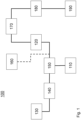
- Fig. 1 shows a schematic illustration of a first embodiment of a braking system 100.
- the braking system 100 can be provided with at least one truck park brake chamber 110 and a trailer service brake 190.
- the truck park brake 110 comprises a fluid connection to the control valve 150.
- the control valve 150 can be a select high valve.
- the control valve 150 can comprise a fluid connection to a secondary supply valve 140 and a truck park brake supply port 120.
- the secondary supply valve 140 can preferably be provided in form of a solenoid valve.
- the braking system 100 comprises a sensor unit 160 being capable of determining/measuring a fluid pressure between the truck park brake supply port 120 and the control valve 150, in particular to determine a fluid pressure leakage and/or a drop/loss of fluid pressure, e.g. by a (sudden) break/rupture of the fluid connection.
- the secondary supply valve 140 comprises a fluid connection with a secondary supply port 130.
- the secondary supply port 130 can preferably be connected to a secondary, in particular redundant, pressure fluid source, like e.g. a trailer pressure fluid tank or the like.
- the truck park brake supply port 120 comprises a fluid connection to at least one truck-trailer valve 170.
- a fluid connection from the truck park brake supply port 120 to a trailer control line port 180 of the braking system 100 can be provided, in order to provide at least comparable fluid pressure, or interrupted.
- the trailer control line port 180 can be provided with pressure fluid/be inflated in order to control at least one trailer service brake (chamber) 190.
- the truck-trailer valve 170 can provide a fluid connection of the truck park brake supply port 120 and/or the trailer control line port 180 with a primary pressure fluid source.
- the braking system 100 can comprise a control unit being capable of controlling and/or regulating the braking system.
- control unit can receive data from the sensor unit 160.
- control unit can be provided to control and/or regulate the secondary supply valve 140, the at least one trailer-truck valve 170 and/or the control valve 150.
- FIG. 2 an embodiment of a method 200 for operating a braking system according to Fig. 1 is illustrated in form of a flow chart.
- a fluid pressure can be checked/measured/determined 210 between the truck park brake supply port 120 and the control valve 150.
- a fluid leakage can be determined 220 on basis of the fluid pressure, preferably as previously determined.
- a fluid leakage can occur either in terms of a break/bust of a fluid connection pipe such that a pressure loss occurs.
- a leakage may be determined 220 on basis of a timeout during the attempt to build up a certain fluid pressure in the fluid connection between the truck park brake supply port 120 and the control valve 150.
- a measurement/determination and/or detection 220 of a fluid leakage can be executed by the sensor unit 160, in particular in combination with a control unit of the braking system 100, e.g. as part of an EPBC or a GSAT.
- the secondary supply valve 140 can be switched 230 in order to provide a fluid connection between the secondary supply port 130 to the control valve 150.
- the higher fluid pressure being supplied via the secondary supply port 130 can be fed through to the truck park brake (chamber(s)).
- the truck-trailer valve 170 can be switched 240 such to allow a fluid pressure being applied on the trailer control line port 180.
- a fluid connection between the truck park brake supply port 120 and the trailer control line port 180 can be interrupted by switching of the at least one trailer-truck valve 170, in order to avoid a loss of fluid pressure due to the leakage between the truck park brake supply port 120 and the control valve 150.
- the switching of the truck-trailer valve 240 can further provide a fluid connection between a primary pressure fluid source of the braking system 100 and the trailer control line port 180.
- a fluid pressure can be applied to the trailer control line port 180 in order to allow for the trailer service breaks 190 to be released.
- the vehicle combination i.e. a truck-trailer combination, having a braking system 100 can be mobilized.
- the functionality of the braking system 100 can be described as follows: In case a truck is parked, the truck park brake supply 120 port and the trailer control line port 180 can have ambient pressure.
- trailer service brakes 190 are actuated, such that moving of the trailer is not possible with rolling wheels.
- the driver/user can request the truck park brake 110 to be deactivated (released/disengaged), by pressurizing/providing fluid pressure at the truck park brake supply port 120 and via the control valve 150 to the truck park brake chamber(s) 110.
- the supply of fluid pressure tp the truck park brake 110, in order to deactivate/release the truck park brake 110, can be stopped.
- the secondary supply valve 140 can be activated/switched 230 in order to provide a fluid connection from the secondary supply port 130 via the control valve 150 to the truck park brake (chamber(s)) 110 for feeding of pressure fluid and thus pressurizing/inflating the truck park brake (chamber(s)) 110.
- the control valve 150 can hereby ensure that the pressure fluid supplied via secondary supply port 130 is forwarded to the truck park brake (chamber(s)) 110.
- the at least one truck-trailer valve 170 can be actuated/switched 240 in order to pressurize the trailer control line port 180, e.g. in parallel, to be able to deactivate trailer service brakes 190.
- the vehicle combination can be moved to another spot.
- the vehicle/truck-trailer combination can be driving (at any speed) while a (sudden) break or leakage occurs between the truck park brake supply port 120 and the control valve 150.
- truck park brake supply port 120 being connected to the trailer control line port 180 via the truck-trailer valve 170, truck park brakes 110 are going to be actuated as well as the trailer service breaks 190 will also apply brake force due to low pressure on the trailer control line port 180.
- the secondary supply valve can be switched/activated 230 in order to provide a redundant pressure fluid supply via the secondary supply port 130 to the truck park brake chamber(s) 110.
- the at least one trailer-truck valve 170 can be actuated 240 in order to pressurize/feed the trailer control line port 180 with pressure fluid, while the truck park brake supply port 120 is disconnected.
- the primary pressure fluid supply for the truck park brake supply port 120 can be switched off as well. At least a fluid connection between the primary pressure fluid supply and the truck park brake supply port 120 can be interrupted by the truck-trailer valve 170.
- the truck-trailer combination is mobilized without allowing a further loss of pressure fluid by the damaged or leaking fluid connection.
- the present invention provides a braking system 100 which comprises an efficient approach for a backup fluid pressure supply without the necessity to include extensive infrastructure. Rather, a leakage or a breakage of a fluid connection, in particular between the truck park brake supply port 120 and the control valve 150, can be compensated on basis of a present secondary pressure fluid source, like a trailer tank, and via switching of the secondary supply valve 140.
- the loss of pressure fluid can be reduced while the truck-trailer/vehicle combination can be mobilized again, by inflation of the truck park brake 110 via the switched secondary supply valve 140 and the independent actuation of trailer service breaks 190 by separate/individual pressurization of the trailer control line port 180.
Landscapes
- Engineering & Computer Science (AREA)
- Transportation (AREA)
- Mechanical Engineering (AREA)
- Valves And Accessory Devices For Braking Systems (AREA)
Abstract
Description
- The present invention refers to a braking system, in particular for a trailer-vehicle combination, a vehicle combination, in particular a truck-trailer combination, and a method for operating the same.
- The today well known and widely applicated park brake chambers are kept in disengaged position via a dedicated pressurized air circuit through the air supply system. If this pressurization is not possible due to a mechanical failure somewhere in the pressurized air circuit, the park brake is being applied, causing brake force on the wheels which are equipped with park brake chambers.
- Furthermore, the trailer pressure control line can also be supplied from the same pressurized air circuit. The behavior is the same as in the previously mentioned situation because the trailer brake control is working in such a way that in case the trailer control line is pressurized, there is no brake force, and the brake force is proportional to a (potentially occurring) decrease of pressure in the trailer control line.
- In conventional systems, a so called redundant backup piping is provided via pneumatic elements by which the mentioned park brake chambers and trailer control line can be pressurized from another pressurized air circuit to avoid park brake / trailer brake application in case of a loss of pressure.
- Considering today's electronic parking brake systems (EPB), if there is a pneumatic line defect between the EPB and the parking brake chambers, the park brake cannot be released, or if this defect occurs during driving, the parking brake cannot be kept released.
- In particular, if pressurized air is lost from the park brake the trailer control line brake force is applied on the wheels. The more the pressure is decreasing, the higher the brake force increases, even up to a complete blockage of the wheel(s).
- Once a wheel is blocked, no lateral tire force can be realized on the ground resulting in a complete loss of controllability of the vehicle, leading to potential life threatening situations, besides the possibility of a (costly) damage of property. To determine the point when the wheel blocking becomes critical is nearly impossible, due to several unknown or fast changing variable(s) such as e.g. the vehicle being loaded or empty, the road conditions (dry asphalt, slippery wet/icy asphalt), driver routine, etc.
- On the other hand, if the park brake is engaged and, due to the damaged pressurized air circuit, it cannot be disengaged, the vehicle is simply fixed in a standstill. Such braking/standstill situation can lead to dangerous situations like in heavy traffic or on a railway crossing.
- According to the state of the art a second pressure supply for the park brake chambers, supplied from a different circuit then the park brake, is provided in order to minimize/avoid such critical situations. In this context, one way of implementation according to the state of the art is to connect the mentioned different pressure supply circuits to the parking brake chambers with a switchable solenoid which is controlled by an electronic control unit (ECU).
- If this ECU detects the (pre-defined) activation conditions - e.g. a pressure breakdown during driving or an attempt to release the parking brake lasting too long without such release occuring - the ECU activates the solenoid and air is supplied to the park brake chambers via the different/secondary pressure circuit. This function is known as "Pipe Fracture Protection" (PFP; in German: Rohrbruchsicherung).
- However, if any of the above-mentioned situations happens, with the layout of the park brake system according to the state of the art, the trailer control line will not be supplied properly, but there could be significant brake force on the trailer. Today's short-term solution for such a situation is to disconnect the (usually yellow) coupling head as well as to release the trailer brakes manually.
- Besides that providing a redundant backup piping, in accordance with the state of the art, increases the build cost of a truck, whereby also the specific reaction time depends on several circumstances. Thereby, the behaviour of a purely pneumatic backup system can also depend on environmental conditions.
- It is an object of the present invention to provide a braking system, in particular for a trailer-vehicle combination, which is capable of providing a backup functionality, e.g. in case of a leakage, a brake pipe burst/break or the like, but also reduces costs and allows for improved behaviour under different (environmental) circumstances, in particular by utilizing a second source of pressure fluid being connectable on a temporarily basis and as needed. Moreover, it is an object of the invention to provide a vehicle combination as well as a method for operating the braking system and/or the vehicle combination.
- This object is solved by a braking system according to independent claim 1 as well as a vehicle combination according to claim 8 and a method for operating of such braking system and/or trailer-vehicle combination according to independent claim 9. Moreover, preferred embodiments are provided in the dependent claims respectively.
- According to the present invention a braking system for a trailer-vehicle combination, in particular for an electronic park brake control (EPBC) system or a global scalable air treatment (GSAT) system of a trailer-vehicle combination, is provided with at least one truck park brake chamber, at least one truck park brake supply port, at least one secondary supply port, at least one secondary supply valve and at least one control valve, preferably a select high valve. The control valve comprises a fluid connection to the at least one truck park brake chamber, the at least one secondary supply valve and the truck park brake supply port, wherein the at least one secondary supply valve comprises a fluid connection to the secondary supply port and to the control valve. The at least one secondary supply valve comprises a fluid connection to the at least one truck park brake chamber via the control valve such that the at least one truck park brake chamber can be provided with pressure fluid via the truck park brake supply port and/or the secondary supply port, preferably to allow for pressure fluid to be provided from a primary pressure fluid source via the truck park brake supply port and/or from a secondary pressure fluid source via the secondary supply port to the at least one truck park brake chamber.
- The invention is based on the idea to combine two functions of a braking system, like e.g. an EPBC system.
- Firstly, in case the brake system detects that the park brake cannot be released, it will actuate the secondary supply valve to supply the truck parking brake chambers with pressure fluid via the secondary supply port and in parallel can (automatically) execute the trailer control line inflation for releasing the trailer service brake, without an attempt to release the truck/tractor's parking brake. By these measures the vehicle combination can be mobilized.
- Secondly, if the EPBC system detects the pressure breakdown of the park brake chambers during driving it can actuate the secondary supply valve to supply the park brake chambers as well as it can, in parallel, automatically activate the trailer control line inflation, thereby keeping the vehicle combination mobilized.
- Moreover, by the present invention the so-called ECE 13 regulation can be met, which defines that the whole vehicle combination must be kept standstill just by the towing vehicle's/tractor's/truck's parking brake when a vehicle combination (e.g. tractor-trailer) is parked. To check the compliance with respect to this ECE 13 regulation, the vehicle combination has to have a function where only the trailer service brakes are released, but the tractor's/towing vehicle's parking brake is kept parked/in braking mode. Such situation is realized by inflation of the trailer control line.
- The braking system according to the present invention can be applied for/with and/or in the context of, in particular as a part of, an EPBC or a GSAT.
- By the at least one secondary supply valve comprising a fluid connection to the secondary supply port and to the control valve it is possible to inflate the truck's/tractor's parking brake (chamber) with pressure fluid either via the truck/tractor park brake supply port or, in particular as a backup option in case of e.g. a pipe burst/breakage, via the secondary supply port.
- According to the present invention the control valve can be an actively and/or a passively controlled valve. Preferably, the control valve can be a (passive) select high valve.
- In particular, the control valve can allow for pressure fluid (or in other words also pressure medium) being fed to the truck park brake chamber from the truck park brake supply port or the secondary supply port.
- Alternatively, the control valve can allow for proportional feeding according to the fluid pressure being applied at the truck park brake supply port and the secondary supply port respectively.
- Moreover, the braking system is preferably configured to be used with air or any other suitable gas as an operational fluid, in particular compressed air. Hence, the braking system can preferably be provided as a pneumatic braking system.
- According to one preferred embodiment the truck park brake supply port and the secondary supply port are capable of providing pressure fluid to the park brake chamber from different, in particular redundant, sources of pressure fluid, preferably from a primary pressure fluid source and a secondary pressure fluid source.
- In particular, by the secondary supply port a secondary source of pressure fluid, independent from the truck park brake supply port, can be utilized, which is provided by the usual infrastructure, e.g. of a GSAT or an EPBC.
- Hence, no additional pressure fluid source or any extensive piping has to be provided. Rather, by the secondary supply valve a simple and cost-efficient backup supply via the secondary supply port can be provided.
- In another embodiment of the invention the braking system further comprises a trailer control line port, for providing pressure fluid to a trailer service brake, and at least one truck-trailer valve, preferably at least one truck-trailer solenoid valve, whereby a fluid connection between a primary pressure fluid source, the truck park brake supply port and/or the trailer control line port is providable via the at least one truck-trailer valve such that at least a (comparable) fluid pressure, preferably the same fluid pressure, can be applied/is applicable at the trailer control line port or at the truck park brake supply port or at both of them simultaneously.
- With the trailer control line port a trailer service break can be controlled, i.e. released, by applying fluid pressure accordingly.
- In particular, the truck-trailer can be utilized to allow for a fluid pressure as provided at the truck park brake supply port to be also or instead available at the trailer control line port.
- Moreover, the at least one truck-trailer valve can connect the trailer control line port to a pressure fluid source.
- Namely, by the at least one truck-trailer valve a fluid connection to the primary pressure fluid source of the braking system can be connected to either the truck park brake supply port, the trailer control line port, to both of them or to none of them.
- In this context, the truck-trailer valve can be implemented in form of a single (solenoid) valve or in form of multiple (solenoid) valves in order to allow for appropriate switching of fluid connections.
- Thereby the trailer's service brake can be released in an efficient manner.
- According to one embodiment the at least one secondary supply valve is provided as a solenoid valve, in particular as a spring-loaded solenoid valve, wherein the at least one secondary supply valve in its deactivated/unswitched/pre-set/spring-loaded state preferably interrupts fluid connection between the secondary supply port and the control valve.
- Hence, the usual operation of the braking system allows for a fluid pressure being applied from the truck park brake supply port via the control valve to the truck park brake (chamber(s)).
- In case of e.g. a brake pipe burst/breakage or a leakage and a corresponding loss/decrease of fluid pressure along such usual supply line, the secondary supply valve can provide for a fluid connection between the secondary supply port and the control valve such that truck park brake (chamber(s)) can be supplied with sufficient pressure fluid to allow for an operation of the truck's parking brake.
- Preferably, the secondary supply valve is a solenoid valve in order to allow a control of the secondary supply valve by a control unit of the braking system and/or the vehicle combination.
- In another preferred embodiment the braking system comprises a sensor unit for detection of a fluid pressure in the fluid connection between the truck park brake supply port and the control valve.
- Such sensor unit can be provided as a specific pressure sensor for measuring the fluid pressure.
- Alternatively, various different methods can be applied in order to directly or indirectly determine a fluid pressure and/or a fluid pressure loss between the truck park brake supply port and the high select valve of the braking system.
- Pursuant to a further embodiment of the invention the secondary supply valve is provided as an external valve, in particular to be controlled via an analogue control connection, or provided as an integral part of the braking system, in particular as an integral part of an electronic park brake control system or of a global scalable air treatment system.
- In particular, the implementation of the secondary supply valve can be provided in various manners, e.g. it can be integrated into the truck system itself, with e.g. a EPBC system only actuating the secondary supply valve via analogue electrical connection. Alternatively, the braking system, in particular the secondary supply valve, can also be directly implemented as an integral part of an EPBC or a GSAT.
- In another preferred embodiment the secondary supply port is a trailer tank supply port and/or comprises a fluid connection to a trailer tank as a secondary pressure fluid source.
- Hence, the secondary supply port and the secondary supply valve can provide a second source of pressure fluid, independent from the truck park brake supply port and its pressure fluid supply.
- According to another aspect, the invention refers to a vehicle combination, in particular a truck-trailer combination, with a braking system according to the present invention. Hence, the braking system, in particular the implementation of the secondary supply valve, can be provided as an integral or an external part of the truck/tractor of such vehicle combination or as a part of the EPBC or GSAT, or the like.
- In a further aspect, the present invention refers to a method for operating a braking system and/or a vehicle combination with a braking system, in particular a braking system and/or a vehicle combination according to the present invention, comprising the following steps:
- checking the fluid pressure between the truck park brake supply port and the control valve;
- detecting a fluid leakage, in particular a loss of fluid pressure below a predeterminable threshold value, between the truck park brake supply port and the control valve;
- switching, in particular activating, the at least one secondary supply valve such that a fluid connection between the secondary supply port and the control valve is provided;
- Hence, the (backup) supply of pressure fluid via the secondary supply valve/secondary supply port can be provided on a temporarily basis and as needed, based on a determined leakage.
- Preferably the method is considered to be executed with/by a braking system using air as an operating fluid, in particular compressed air.
- The control valve hereby ensures that the higher fluid pressure applied either at the truck park brake supply port or via the (activated/connected) secondary supply valve can provide/feed sufficient pressure fluid to the truck park brake chamber(s). According to one preferred embodiment the step of checking the fluid pressure is at least executed when pressure fluid is provided to the truck park brake supply port, preferably at least once or on a regular timely basis.
- In particular, by a regular check of the fluid pressure a fluid pressure leakage between the truck park brake supply port and the control valve can be determined.
- Preferably the braking system can comprise a control unit for analyzing and/or processing measurements, e.g. by the sensor unit. Moreover, the control unit can be provided to control and/or regulate valves, like the secondary supply valve and/or the truck-trailer valve, in a suitable manner.
- Moreover, a braking system and/or a vehicle combination according to the present invention is preferably considered to be configured to allow the execution of a method according to the present invention.
- In a further embodiment the truck-trailer valve is switched, subsequently or simultaneously to the switching of the at least one secondary supply valve, such that a fluid connection between the primary pressure fluid source, the truck park brake supply port and/or trailer control line port is established in order to provide a fluid pressure to the trailer control line port, in particular to release a trailer service brake.
- In particular, by the at least one truck-trailer valve the truck park brake supply port can be disconnected from the primary pressure fluid source of the braking system to avoid unnecessary loss of pressure fluid via the leakage/ruptured/broken fluid connection. Instead, only the trailer control line port can be connected with the primary pressure fluid supply in order to allow for a suitable handling of the trailer service brakes.
- Thus, in particular in case of the secondary supply valve providing a fluid connection to supply pressure fluid to the truck park brake chamber(s), the trailer control line can be fed with pressure fluid to allow for an independent, at least partial, release of the trailer service brake.
- According to another embodiment the secondary supply valve is switched, preferably activated, to provide a fluid connection between the secondary supply port and the truck park brake chamber via the control valve when
- when a fluid pressure between the truck park brake supply port and the control valve is lower than a predeterminable threshold value, in particular below a contact pressure threshold, or
- when a predeterminable threshold value of fluid pressure is not providable within a predeterminable time range.
- Hence, in case of a leakage or a (sudden) burst/breakage of fluid connection between the truck park brake supply port and the control valve a sufficient and appropriate pressure fluid supply can be ensured via switching of the secondary supply valve to provide pressure fluid from the secondary supply port via the control valve to the truck park brake chamber(s).
- For example, in case of an EPBC an EPB detection routine can check whether there is an implausible high negative gradient on the truck's park brake chamber pressure, e.g. in case of a sudden pipe breaking, or whether this pressure simply falls short a certain threshold. A precondition for such routine can be that the truck's parking brake is released.
- The pre-determinable threshold can be a so-called contact pressure threshold which means that the brake pads are in contact with the brake disc/drum and that a brake force can be present/provided.
- Alternatively, another EPBC detection routine can occur when the truck's park brake is in parked position (engaged). With an intact system, there is a well-defined timeout within which the parking brake chamber pressure has to reach the released pressure threshold (assuming that there is enough supply pressure to reach this pressure threshold).
- In this case, the EPBC's detection routine can start a counter when a request to release the truck's park brake is received. The counter can be compared to a pre-defined threshold. This comparison either results in a failed release attempt or is terminated when the target pressure threshold is reached within the pre-definable timeout.
- Hence, an advantageous control and/or regulation for checking of the regular operation of the braking system can be provided.
- In another embodiment, the predeterminable threshold value of fluid pressure is about 8 bar.
- In particular, if the trailer control line port is pressurized to more than eight (8) bar, there is no brake force on the trailer service break. However, if the pressure is decreased on the trailer control line (port) down to zero (0) bar, proportional to it, brake force is present on the trailer service brakes.
- All of the structural and functional features as described above in the context of the braking system according to the present invention as well as its embodiments can be considered for or applied/used, alone or in combination with each other, for a method according to the present invention in order to achieve the advantages being associated therewith respectively.
- Further details and advantages of the invention will be described and outlined in the following with respect to embodiments as illustrated in the enclosed figures.
- It is shown:
- Fig. 1
- a schematic illustration of a first embodiment of a braking system; and
- Fig. 2
- a flow chart of a method for operating a braking system according to
Fig. 1 . -
Fig. 1 shows a schematic illustration of a first embodiment of abraking system 100. Thebraking system 100 can be provided with at least one truckpark brake chamber 110 and atrailer service brake 190. - The
truck park brake 110 comprises a fluid connection to thecontrol valve 150. Preferably, thecontrol valve 150 can be a select high valve. - The
control valve 150 can comprise a fluid connection to asecondary supply valve 140 and a truck parkbrake supply port 120. - The
secondary supply valve 140 can preferably be provided in form of a solenoid valve. Moreover, thebraking system 100 comprises asensor unit 160 being capable of determining/measuring a fluid pressure between the truck parkbrake supply port 120 and thecontrol valve 150, in particular to determine a fluid pressure leakage and/or a drop/loss of fluid pressure, e.g. by a (sudden) break/rupture of the fluid connection. Thesecondary supply valve 140 comprises a fluid connection with asecondary supply port 130. - The
secondary supply port 130 can preferably be connected to a secondary, in particular redundant, pressure fluid source, like e.g. a trailer pressure fluid tank or the like. - The truck park
brake supply port 120 comprises a fluid connection to at least one truck-trailer valve 170. - Via the at least one truck-
trailer valve 170, a fluid connection from the truck parkbrake supply port 120 to a trailercontrol line port 180 of thebraking system 100 can be provided, in order to provide at least comparable fluid pressure, or interrupted. - The trailer
control line port 180 can be provided with pressure fluid/be inflated in order to control at least one trailer service brake (chamber) 190. - The truck-
trailer valve 170 can provide a fluid connection of the truck parkbrake supply port 120 and/or the trailercontrol line port 180 with a primary pressure fluid source. - The
braking system 100 can comprise a control unit being capable of controlling and/or regulating the braking system. - In particular, the control unit can receive data from the
sensor unit 160. - Moreover, the control unit can be provided to control and/or regulate the
secondary supply valve 140, the at least one trailer-truck valve 170 and/or thecontrol valve 150. - In
Fig. 2 an embodiment of amethod 200 for operating a braking system according toFig. 1 is illustrated in form of a flow chart. - In one step a fluid pressure can be checked/measured/determined 210 between the truck park
brake supply port 120 and thecontrol valve 150. - In another step, a fluid leakage can be determined 220 on basis of the fluid pressure, preferably as previously determined.
- A fluid leakage can occur either in terms of a break/bust of a fluid connection pipe such that a pressure loss occurs.
- Alternatively, a leakage may be determined 220 on basis of a timeout during the attempt to build up a certain fluid pressure in the fluid connection between the truck park
brake supply port 120 and thecontrol valve 150. - Preferably, a measurement/determination and/or
detection 220 of a fluid leakage can be executed by thesensor unit 160, in particular in combination with a control unit of thebraking system 100, e.g. as part of an EPBC or a GSAT. - In a further step, the
secondary supply valve 140 can be switched 230 in order to provide a fluid connection between thesecondary supply port 130 to thecontrol valve 150. - In case of a leakage between the truck park
brake supply port 120 and thecontrol valve 150, the higher fluid pressure being supplied via thesecondary supply port 130 can be fed through to the truck park brake (chamber(s)). - Subsequently or simultaneously, the truck-
trailer valve 170 can be switched 240 such to allow a fluid pressure being applied on the trailercontrol line port 180. - In particular, a fluid connection between the truck park
brake supply port 120 and the trailercontrol line port 180 can be interrupted by switching of the at least one trailer-truck valve 170, in order to avoid a loss of fluid pressure due to the leakage between the truck parkbrake supply port 120 and thecontrol valve 150. - The switching of the truck-
trailer valve 240 can further provide a fluid connection between a primary pressure fluid source of thebraking system 100 and the trailercontrol line port 180. - Preferably, a fluid pressure can be applied to the trailer
control line port 180 in order to allow for the trailer service breaks 190 to be released. - By the
method 200, the vehicle combination, i.e. a truck-trailer combination, having abraking system 100 can be mobilized. - In more detail, the functionality of the
braking system 100 can be described as follows: In case a truck is parked, the truckpark brake supply 120 port and the trailercontrol line port 180 can have ambient pressure. - Thereby, the trailer is not parked, but
trailer service brakes 190 are actuated, such that moving of the trailer is not possible with rolling wheels. - The driver/user can request the
truck park brake 110 to be deactivated (released/disengaged), by pressurizing/providing fluid pressure at the truck parkbrake supply port 120 and via thecontrol valve 150 to the truck park brake chamber(s) 110. - If a break/rupture/leakage occurs between the truck park
brake supply port 120 and thecontrol valve 150 and the break cross section/leakage is large enough, no or only a minimal pressure increase will occur at the truck parkbrake supply port 120. - By detection of such lack of
fluid pressure 210; 220, preferably by thesensor unit 160 in combination with a control unit of thebraking system 100, the supply of fluid pressure tp thetruck park brake 110, in order to deactivate/release thetruck park brake 110, can be stopped. - In a next step, the
secondary supply valve 140 can be activated/switched 230 in order to provide a fluid connection from thesecondary supply port 130 via thecontrol valve 150 to the truck park brake (chamber(s)) 110 for feeding of pressure fluid and thus pressurizing/inflating the truck park brake (chamber(s)) 110. - The
control valve 150 can hereby ensure that the pressure fluid supplied viasecondary supply port 130 is forwarded to the truck park brake (chamber(s)) 110. - Preferably, in parallel, or subsequently, the at least one truck-
trailer valve 170 can be actuated/switched 240 in order to pressurize the trailercontrol line port 180, e.g. in parallel, to be able to deactivatetrailer service brakes 190. - By switching 240 of the at least one truck-
trailer valve 170 also a fluid connection between the primary pressure fluid source of thebraking system 100 and/or the trailercontrol line port 180 to the truck parkbrake supply port 120 can be interrupted in order to (ongoing) avoid loss of pressure fluid/fluid pressure due to the leakage/pipe breakage. - In consequence, the vehicle combination can be moved to another spot.
- In another situation, the vehicle/truck-trailer combination can be driving (at any speed) while a (sudden) break or leakage occurs between the truck park
brake supply port 120 and thecontrol valve 150. - As a consequence, a rapid and/or relevant fluid pressure drop occur at the trailer
control line port 180 and can be detected 210; 220. - By the truck park
brake supply port 120 being connected to the trailercontrol line port 180 via the truck-trailer valve 170,truck park brakes 110 are going to be actuated as well as the trailer service breaks 190 will also apply brake force due to low pressure on the trailercontrol line port 180. - In a next step, the secondary supply valve can be switched/activated 230 in order to provide a redundant pressure fluid supply via the
secondary supply port 130 to the truck park brake chamber(s) 110. - Subsequently or in parallel, the at least one trailer-
truck valve 170 can be actuated 240 in order to pressurize/feed the trailercontrol line port 180 with pressure fluid, while the truck parkbrake supply port 120 is disconnected. - If the actuations, in particular of the
truck park brake 110 and thetrailer service brake 190, are completed, the primary pressure fluid supply for the truck parkbrake supply port 120 can be switched off as well. At least a fluid connection between the primary pressure fluid supply and the truck parkbrake supply port 120 can be interrupted by the truck-trailer valve 170. - The truck-trailer combination is mobilized without allowing a further loss of pressure fluid by the damaged or leaking fluid connection.
- In summary, the present invention provides a
braking system 100 which comprises an efficient approach for a backup fluid pressure supply without the necessity to include extensive infrastructure. Rather, a leakage or a breakage of a fluid connection, in particular between the truck parkbrake supply port 120 and thecontrol valve 150, can be compensated on basis of a present secondary pressure fluid source, like a trailer tank, and via switching of thesecondary supply valve 140. - In consequence, the loss of pressure fluid can be reduced while the truck-trailer/vehicle combination can be mobilized again, by inflation of the
truck park brake 110 via the switchedsecondary supply valve 140 and the independent actuation of trailer service breaks 190 by separate/individual pressurization of the trailercontrol line port 180. -
- 100
- Braking system
- 110
- Truck park brake (chamber(s))
- 120
- Truck park brake supply port
- 130
- Secondary supply port
- 140
- Secondary supply valve
- 150
- Control valve/Select high valve
- 160
- Sensor unit
- 170
- Truck-trailer valve
- 180
- Trailer control line port
- 190
- Trailer service break (chamber(s))
- 200
- Method
- 210
- Checking of fluid pressure
- 220
- Detecting/Determining a fluid leakage
- 230
- Switching secondary supply valve
- 240
- Switching truck-trailer valve
Claims (13)
- Braking system (100) for a trailer-vehicle combination, in particular for an electronic park brake control system or a global scalable air treatment system of a trailer-vehicle combination,comprising at least one truck park brake chamber (110), at least one truck park brake supply port (120), at least one secondary supply port (130), at least one secondary supply valve (140) and at least one control valve (150), preferably a select high valve, wherein the control valve (150) comprises a fluid connection to the at least one truck park brake chamber (110), the at least one secondary supply valve (130) and the truck park brake supply port (120),wherein the at least one secondary supply valve (140) comprises a fluid connection to the secondary supply port (130) and to the control valve (150),wherein the at least one secondary supply valve (140) comprises a fluid connection to the at least one truck park brake chamber (110) via the control valve (150) such that the at least one truck park brake chamber (110) can be provided with pressure fluid via the truck park brake supply port (120) and/or the secondary supply port (130), preferably to allow for pressure fluid to be provided from a primary pressure fluid source via the truck park brake supply port (120) and/or from a secondary pressure fluid source via the secondary supply port (140) to the at least one truck park brake chamber (110).
- Braking system (100) according to claim 1,
characterized in that
the truck park brake supply port (120) and the secondary supply port (130) are capable of providing pressure fluid to the truck park brake chamber (110) from different, in particular redundant, sources of pressure fluid, preferably from a primary pressure fluid source and a secondary pressure fluid source. - Braking system (100) according to one of the preceding claims,
characterized in thatthe braking system (100) further comprises a trailer control line port (180), for providing pressure fluid to a trailer service brake (190), and at least one truck-trailer valve (170), preferably at least one truck-trailer solenoid valve,wherein a fluid connection between a primary pressure fluid source, the truck park brake supply port (120) and/or the trailer control line port (180) is providable via the at least one truck-trailer valve (170) such that at least a comparable fluid pressure can be applied at the trailer control line port (180) or at the truck park brake supply port (120) or at both of them (120; 180) simultaneously. - Braking system (100) according to one of the preceding claims,
characterized in thatthe at least one secondary supply valve (140) is provided as a solenoid valve, in particular as a spring-loaded solenoid valve,whereby the at least one secondary supply valve (140) in its deactivated state preferably interrupts fluid connection between the secondary supply port (130) and the control valve (150). - Braking system (100) according to one of the preceding claims,
characterized in that
the braking system (100) comprises a sensor unit (160) for detection of a fluid pressure in the fluid connection between the truck park brake supply port (120) and the control valve (150). - Braking system (100) according to one of the preceding claims,
characterized in that
the secondary supply valve (140) is provided as an external valve, in particular to be controlled via an analogue control connection, or provided as an integral part of the braking system (100), in particular as an integral part of an electronic park brake control system or of an global scalable air treatment system. - Braking system (100) according to one of the preceding claims,
characterized in that
the secondary supply port (130) is a trailer tank supply port and/or comprises a fluid connection to a trailer tank as a secondary pressure fluid source. - Vehicle combination, in particular a truck-trailer combination, with a braking system (100) according to one of the preceding claims.
- Method (200) for operating a braking system and/or a vehicle combination, in particular a braking system (100) and/or a vehicle combination according to one of the preceding claims, comprising the following steps:- checking (210) the fluid pressure between the truck park brake supply port (120) and the control valve (150);- detecting (220) a fluid leakage, in particular a loss of fluid pressure below a predeterminable threshold value, between the truck park brake supply port (120) and the control valve (150);- switching (230), in particular activating, the at least one secondary supply valve (140) such that a fluid connection between the secondary supply port (130) and the control valve (150) is provided;wherein pressure fluid can be provided from the secondary supply port (130) of the braking system (100) via the control valve (150) to the truck park brake chamber (110).
- Method (200) according to claim 9,
characterized in that
the step of checking (210) the fluid pressure is at least executed when pressure fluid is provided to the truck park brake supply port (120). - Method (200) according to claim 9 or 10,
characterized in that
the truck-trailer valve (170) is switched (240), subsequently or simultaneously to the switching (230) of the at least one secondary supply valve (140), such that a fluid connection between the primary pressure fluid source, the truck park brake supply port (120) and/or trailer control line port (180) is established in order to provide a fluid pressure to the trailer control line port (180), in particular to release a trailer service brake (190). - Method (200) according to one of claims 9 to 11,
characterized in that
the secondary supply valve (140) is switched, preferably activated, to provide a fluid connection between the secondary supply port (130) and the truck park brake chamber (110) via the control valve (150) when- when a fluid pressure between the truck park brake supply port (120) and the control valve (150) is lower than a predeterminable threshold value, in particular below a contact pressure threshold, or- when a predeterminable threshold value of fluid pressure is not providable within a predeterminable time range. - Method (200) according to claim 9 to 12,
characterized in that
the predeterminable threshold value of fluid pressure is about 8 bar.
Priority Applications (3)
| Application Number | Priority Date | Filing Date | Title |
|---|---|---|---|
| EP22191386.6A EP4328102B1 (en) | 2022-08-22 | 2022-08-22 | Braking system, vehicle combination and method of operating the same |
| CN202380061332.8A CN119768318A (en) | 2022-08-22 | 2023-07-31 | Braking system, vehicle combination and method of operating the same |
| PCT/EP2023/071197 WO2024041852A1 (en) | 2022-08-22 | 2023-07-31 | Braking system, vehicle combination and method of operating the same |
Applications Claiming Priority (1)
| Application Number | Priority Date | Filing Date | Title |
|---|---|---|---|
| EP22191386.6A EP4328102B1 (en) | 2022-08-22 | 2022-08-22 | Braking system, vehicle combination and method of operating the same |
Publications (2)
| Publication Number | Publication Date |
|---|---|
| EP4328102A1 true EP4328102A1 (en) | 2024-02-28 |
| EP4328102B1 EP4328102B1 (en) | 2026-01-07 |
Family
ID=83006090
Family Applications (1)
| Application Number | Title | Priority Date | Filing Date |
|---|---|---|---|
| EP22191386.6A Active EP4328102B1 (en) | 2022-08-22 | 2022-08-22 | Braking system, vehicle combination and method of operating the same |
Country Status (3)
| Country | Link |
|---|---|
| EP (1) | EP4328102B1 (en) |
| CN (1) | CN119768318A (en) |
| WO (1) | WO2024041852A1 (en) |
Citations (3)
| Publication number | Priority date | Publication date | Assignee | Title |
|---|---|---|---|---|
| US5190357A (en) * | 1991-05-24 | 1993-03-02 | International Transquip Industries, Inc. | Air-actuated brake system for vehicles |
| US20060076823A1 (en) * | 2004-10-12 | 2006-04-13 | Soupal Thomas R | Park brake interlock and trailer brake valve assembly |
| CN108501922A (en) * | 2018-05-17 | 2018-09-07 | 浙江万安科技股份有限公司 | A kind of air-pressure type electronic parking system |
-
2022
- 2022-08-22 EP EP22191386.6A patent/EP4328102B1/en active Active
-
2023
- 2023-07-31 CN CN202380061332.8A patent/CN119768318A/en active Pending
- 2023-07-31 WO PCT/EP2023/071197 patent/WO2024041852A1/en not_active Ceased
Patent Citations (3)
| Publication number | Priority date | Publication date | Assignee | Title |
|---|---|---|---|---|
| US5190357A (en) * | 1991-05-24 | 1993-03-02 | International Transquip Industries, Inc. | Air-actuated brake system for vehicles |
| US20060076823A1 (en) * | 2004-10-12 | 2006-04-13 | Soupal Thomas R | Park brake interlock and trailer brake valve assembly |
| CN108501922A (en) * | 2018-05-17 | 2018-09-07 | 浙江万安科技股份有限公司 | A kind of air-pressure type electronic parking system |
Also Published As
| Publication number | Publication date |
|---|---|
| EP4328102B1 (en) | 2026-01-07 |
| WO2024041852A1 (en) | 2024-02-29 |
| CN119768318A (en) | 2025-04-04 |
Similar Documents
| Publication | Publication Date | Title |
|---|---|---|
| US11535068B2 (en) | Load-based tire inflation system for heavy-duty vehicles | |
| CN101622164B (en) | Parking brake device of a vehicle with emergency release function and method for operating such a parking brake device | |
| CN108025723B (en) | Vehicle trailer braking system and method | |
| KR101278379B1 (en) | Brake device for a vehicle with an electric parking brake system and corresponding control method | |
| US9415759B2 (en) | Vehicle monitoring system with multiple inputs for a tractor-trailer | |
| CN107709108B (en) | Electric braking device with parking brake operable by service brake operating mechanism | |
| US10946842B2 (en) | Modular trailer system | |
| US8702179B2 (en) | Vehicle brake system | |
| CN103025546A (en) | Tire inflation system with discrete deflation circuit | |
| CN112533805B (en) | Electropneumatic parking brake system with shut-off valve and method for controlling an electronically controlled pneumatic brake system | |
| US20240157927A1 (en) | Method for checking functioning of a pressure-medium operated electronic brake system of a vehicle | |
| EP2462012B1 (en) | Trailer park brake valve arrangement | |
| US20240001900A1 (en) | Trailer Brake Control System | |
| US20240190410A1 (en) | Tractor Protection System and Method | |
| US20090079146A1 (en) | Axle air dump for multiple axle vehicles | |
| EP3162645B1 (en) | Brake system and brake control method | |
| EP4328102B1 (en) | Braking system, vehicle combination and method of operating the same | |
| US20070046098A1 (en) | Vehicle stability system diagnostic method | |
| CN114364585B (en) | Brake system for a commercial vehicle | |
| US12084010B2 (en) | Method and system of hydraulic braking for vehicle with coupling | |
| RU2394708C2 (en) | Automotive braking system with pneumatic drive | |
| EP4733157A1 (en) | Method for providing a secondary parking brake operation of a commercial vehicle | |
| US20250187575A1 (en) | Brake system of a vehicle with redundant parking brake function |
Legal Events
| Date | Code | Title | Description |
|---|---|---|---|
| PUAI | Public reference made under article 153(3) epc to a published international application that has entered the european phase |
Free format text: ORIGINAL CODE: 0009012 |
|
| STAA | Information on the status of an ep patent application or granted ep patent |
Free format text: STATUS: THE APPLICATION HAS BEEN PUBLISHED |
|
| AK | Designated contracting states |
Kind code of ref document: A1 Designated state(s): AL AT BE BG CH CY CZ DE DK EE ES FI FR GB GR HR HU IE IS IT LI LT LU LV MC MK MT NL NO PL PT RO RS SE SI SK SM TR |
|
| STAA | Information on the status of an ep patent application or granted ep patent |
Free format text: STATUS: REQUEST FOR EXAMINATION WAS MADE |
|
| 17P | Request for examination filed |
Effective date: 20240828 |
|
| RBV | Designated contracting states (corrected) |
Designated state(s): AL AT BE BG CH CY CZ DE DK EE ES FI FR GB GR HR HU IE IS IT LI LT LU LV MC MK MT NL NO PL PT RO RS SE SI SK SM TR |
|
| GRAP | Despatch of communication of intention to grant a patent |
Free format text: ORIGINAL CODE: EPIDOSNIGR1 |
|
| STAA | Information on the status of an ep patent application or granted ep patent |
Free format text: STATUS: GRANT OF PATENT IS INTENDED |
|
| INTG | Intention to grant announced |
Effective date: 20250808 |
|
| GRAS | Grant fee paid |
Free format text: ORIGINAL CODE: EPIDOSNIGR3 |
|
| GRAA | (expected) grant |
Free format text: ORIGINAL CODE: 0009210 |
|
| STAA | Information on the status of an ep patent application or granted ep patent |
Free format text: STATUS: THE PATENT HAS BEEN GRANTED |
|
| P01 | Opt-out of the competence of the unified patent court (upc) registered |
Free format text: CASE NUMBER: UPC_APP_0011981_4328102/2025 Effective date: 20251103 |
|
| AK | Designated contracting states |
Kind code of ref document: B1 Designated state(s): AL AT BE BG CH CY CZ DE DK EE ES FI FR GB GR HR HU IE IS IT LI LT LU LV MC MK MT NL NO PL PT RO RS SE SI SK SM TR |
|
| REG | Reference to a national code |
Ref country code: CH Ref legal event code: F10 Free format text: ST27 STATUS EVENT CODE: U-0-0-F10-F00 (AS PROVIDED BY THE NATIONAL OFFICE) Effective date: 20260107 Ref country code: GB Ref legal event code: FG4D |
|
| REG | Reference to a national code |
Ref country code: DE Ref legal event code: R096 Ref document number: 602022028288 Country of ref document: DE |
|
| REG | Reference to a national code |
Ref country code: IE Ref legal event code: FG4D |
|
| REG | Reference to a national code |
Ref country code: NL Ref legal event code: MP Effective date: 20260107 |
|
| PG25 | Lapsed in a contracting state [announced via postgrant information from national office to epo] |
Ref country code: NL Free format text: LAPSE BECAUSE OF FAILURE TO SUBMIT A TRANSLATION OF THE DESCRIPTION OR TO PAY THE FEE WITHIN THE PRESCRIBED TIME-LIMIT Effective date: 20260107 |
|
| REG | Reference to a national code |
Ref country code: AT Ref legal event code: MK05 Ref document number: 1875468 Country of ref document: AT Kind code of ref document: T Effective date: 20260107 |
|
| PG25 | Lapsed in a contracting state [announced via postgrant information from national office to epo] |
Ref country code: RS Free format text: LAPSE BECAUSE OF FAILURE TO SUBMIT A TRANSLATION OF THE DESCRIPTION OR TO PAY THE FEE WITHIN THE PRESCRIBED TIME-LIMIT Effective date: 20260407 |
|
| PG25 | Lapsed in a contracting state [announced via postgrant information from national office to epo] |
Ref country code: ES Free format text: LAPSE BECAUSE OF FAILURE TO SUBMIT A TRANSLATION OF THE DESCRIPTION OR TO PAY THE FEE WITHIN THE PRESCRIBED TIME-LIMIT Effective date: 20260107 |
|
| PG25 | Lapsed in a contracting state [announced via postgrant information from national office to epo] |
Ref country code: PL Free format text: LAPSE BECAUSE OF FAILURE TO SUBMIT A TRANSLATION OF THE DESCRIPTION OR TO PAY THE FEE WITHIN THE PRESCRIBED TIME-LIMIT Effective date: 20260107 |
|
| PG25 | Lapsed in a contracting state [announced via postgrant information from national office to epo] |
Ref country code: GR Free format text: LAPSE BECAUSE OF FAILURE TO SUBMIT A TRANSLATION OF THE DESCRIPTION OR TO PAY THE FEE WITHIN THE PRESCRIBED TIME-LIMIT Effective date: 20260408 |
|
| REG | Reference to a national code |
Ref country code: LT Ref legal event code: MG9D |
|
| PG25 | Lapsed in a contracting state [announced via postgrant information from national office to epo] |
Ref country code: LT Free format text: LAPSE BECAUSE OF FAILURE TO SUBMIT A TRANSLATION OF THE DESCRIPTION OR TO PAY THE FEE WITHIN THE PRESCRIBED TIME-LIMIT Effective date: 20260107 |
|
| PG25 | Lapsed in a contracting state [announced via postgrant information from national office to epo] |
Ref country code: NO Free format text: LAPSE BECAUSE OF FAILURE TO SUBMIT A TRANSLATION OF THE DESCRIPTION OR TO PAY THE FEE WITHIN THE PRESCRIBED TIME-LIMIT Effective date: 20260407 |
|
| PG25 | Lapsed in a contracting state [announced via postgrant information from national office to epo] |
Ref country code: AT Free format text: LAPSE BECAUSE OF FAILURE TO SUBMIT A TRANSLATION OF THE DESCRIPTION OR TO PAY THE FEE WITHIN THE PRESCRIBED TIME-LIMIT Effective date: 20260107 Ref country code: FI Free format text: LAPSE BECAUSE OF FAILURE TO SUBMIT A TRANSLATION OF THE DESCRIPTION OR TO PAY THE FEE WITHIN THE PRESCRIBED TIME-LIMIT Effective date: 20260107 |
|
| PG25 | Lapsed in a contracting state [announced via postgrant information from national office to epo] |
Ref country code: HR Free format text: LAPSE BECAUSE OF FAILURE TO SUBMIT A TRANSLATION OF THE DESCRIPTION OR TO PAY THE FEE WITHIN THE PRESCRIBED TIME-LIMIT Effective date: 20260107 |
|
| PG25 | Lapsed in a contracting state [announced via postgrant information from national office to epo] |
Ref country code: IS Free format text: LAPSE BECAUSE OF FAILURE TO SUBMIT A TRANSLATION OF THE DESCRIPTION OR TO PAY THE FEE WITHIN THE PRESCRIBED TIME-LIMIT Effective date: 20260507 Ref country code: PT Free format text: LAPSE BECAUSE OF FAILURE TO SUBMIT A TRANSLATION OF THE DESCRIPTION OR TO PAY THE FEE WITHIN THE PRESCRIBED TIME-LIMIT Effective date: 20260507 |
|
| PG25 | Lapsed in a contracting state [announced via postgrant information from national office to epo] |
Ref country code: LV Free format text: LAPSE BECAUSE OF FAILURE TO SUBMIT A TRANSLATION OF THE DESCRIPTION OR TO PAY THE FEE WITHIN THE PRESCRIBED TIME-LIMIT Effective date: 20260107 |
|
| PG25 | Lapsed in a contracting state [announced via postgrant information from national office to epo] |
Ref country code: BG Free format text: LAPSE BECAUSE OF FAILURE TO SUBMIT A TRANSLATION OF THE DESCRIPTION OR TO PAY THE FEE WITHIN THE PRESCRIBED TIME-LIMIT Effective date: 20260107 |