EP4328084A1 - Supporting leg telescopic locking structure and child safety seat - Google Patents
Supporting leg telescopic locking structure and child safety seat Download PDFInfo
- Publication number
- EP4328084A1 EP4328084A1 EP22848141.2A EP22848141A EP4328084A1 EP 4328084 A1 EP4328084 A1 EP 4328084A1 EP 22848141 A EP22848141 A EP 22848141A EP 4328084 A1 EP4328084 A1 EP 4328084A1
- Authority
- EP
- European Patent Office
- Prior art keywords
- support leg
- locking
- base
- pedestal
- secondary lock
- Prior art date
- Legal status (The legal status is an assumption and is not a legal conclusion. Google has not performed a legal analysis and makes no representation as to the accuracy of the status listed.)
- Granted
Links
Images




Classifications
-
- B—PERFORMING OPERATIONS; TRANSPORTING
- B60—VEHICLES IN GENERAL
- B60N—SEATS SPECIALLY ADAPTED FOR VEHICLES; VEHICLE PASSENGER ACCOMMODATION NOT OTHERWISE PROVIDED FOR
- B60N2/00—Seats specially adapted for vehicles; Arrangement or mounting of seats in vehicles
- B60N2/24—Seats specially adapted for vehicles; Arrangement or mounting of seats in vehicles for particular purposes or particular vehicles
- B60N2/26—Seats specially adapted for vehicles; Arrangement or mounting of seats in vehicles for particular purposes or particular vehicles for children
- B60N2/28—Seats readily mountable on, and dismountable from, existing seats or other parts of the vehicle
- B60N2/2821—Seats readily mountable on, and dismountable from, existing seats or other parts of the vehicle having a seat and a base part
- B60N2/2824—Seats readily mountable on, and dismountable from, existing seats or other parts of the vehicle having a seat and a base part part of the base being supported by the vehicle frame
-
- B—PERFORMING OPERATIONS; TRANSPORTING
- B60—VEHICLES IN GENERAL
- B60N—SEATS SPECIALLY ADAPTED FOR VEHICLES; VEHICLE PASSENGER ACCOMMODATION NOT OTHERWISE PROVIDED FOR
- B60N2/00—Seats specially adapted for vehicles; Arrangement or mounting of seats in vehicles
- B60N2/24—Seats specially adapted for vehicles; Arrangement or mounting of seats in vehicles for particular purposes or particular vehicles
- B60N2/26—Seats specially adapted for vehicles; Arrangement or mounting of seats in vehicles for particular purposes or particular vehicles for children
- B60N2/28—Seats readily mountable on, and dismountable from, existing seats or other parts of the vehicle
Definitions
- the present disclosure relates to the technical field of child safety seats, and particularly to a telescopic support leg locking structure and a child safety seat including the same.
- a support leg is generally arranged at the front end of the base of the child safety seat. The support leg can be folded up when the child safety seat does not need to be used.
- the present disclosure first provides a telescopic support leg locking structure, including a base, a support leg pedestal, and a support leg, where the support leg pedestal is slidably connected to the base, and the support leg is hingedly connected to the support leg pedestal; and the telescopic support leg locking structure further includes a secondary lock, where the support leg pedestal is provided with a chamber for the secondary lock to slide vertically, the secondary lock includes a locking tongue configured to abut against the support leg, the chamber is provided with a lower opening for the locking tongue to extend out therethrough, the base is provided with a locking hole, and when the support leg is separated from the locking tongue, the locking tongue is locked with the locking hole to restrict the support leg pedestal from moving forward and backward relative to the base.
- a secondary lock where the support leg pedestal is provided with a chamber for the secondary lock to slide vertically, the secondary lock includes a locking tongue configured to abut against the support leg, the chamber is provided with a lower opening for the locking tongue to extend out therethrough, the base is provided with
- the base is provided with a first rail for the support leg pedestal to slide forward and backward, and a sliding column configured to engage with the first rail is arranged on the support leg pedestal.
- the sliding column is connected to a fastener configured to prevent the sliding column from disengaging from the first rail.
- a front end of the first rail is in communication with the locking hole.
- the locking tongue includes a locking portion and a sliding portion connected to a lower end of the locking portion, the locking portion is engaged with the locking hole when the locking tongue is locked with the locking hole, and the sliding portion is configured to be slidably connected to the first rail when the locking tongue is unlocked from the locking hole.
- the telescopic support leg locking structure further includes a connecting rod extending through the support leg pedestal, and the base is provided with a second rail configured to engage with the connecting rod.
- the support leg pedestal includes a lower cover and a fixing plate connected to each other, the chamber is arranged on the lower cover, and a restoring spring is arranged between the secondary lock and the fixing plate.
- a connecting portion is arranged at a top of the secondary lock, and a baffle plate configured to engage with the connecting portion is arranged at the lower opening.
- a plurality of slide grooves are provided in a circumferential direction of the connecting portion, and slide rails configured to slidably engage with the slide grooves are correspondingly arranged on an inner wall of the chamber.
- the secondary lock configured to lock the support leg in an unfolded state with the base is arranged, and the locking tongue of the secondary lock can be unlocked from the locking hole of the base and locked with the locking hole of the base by folding and unfolding the support leg, respectively.
- Such a structure is simple and is convenient and reliable to operate, and ensures that the support leg in the unfolded state can remain in the state of being locked with the base. Therefore, the support leg can be prevented from retracting when a vehicle accident occurs, thereby ensuring that the support leg can effectively support a child safety seat and greatly improving the safety in use.
- the present disclosure provides a child safety seat, including the telescopic support leg locking structure as described above.
- the child safety seat of the present disclosure has the same advantages as those of the telescopic support leg locking structure compared with the prior art, so the details will not be repeated herein.
- orientation or position relationships indicated by the terms such as “upper” and “lower” are orientation or position relationships based on the normal use of the product.
- a coordinate system XYZ is provided, where the positive direction of the X axis represents left, the negative direction of the X axis represents right, the positive direction of the Y axis represents front, the negative direction of the Y axis represents rear, the positive direction of the Z axis represents up, and the negative direction of the Z axis represents down.
- the telescopic support leg locking structure includes a base 1, a support leg pedestal 2, and a support leg 3.
- the support leg pedestal 2 is slidably connected to the base 1.
- the support leg 3 is hingedly connected to the support leg pedestal 2.
- the telescopic support leg locking structure further includes a secondary lock 4.
- the support leg pedestal 2 is provided with a chamber 211 for the secondary lock 4 to slide vertically.
- the secondary lock 4 includes a locking tongue 41 configured to abut against the support leg 3.
- the chamber 211 is provided with a lower opening 2111 for the locking tongue 41 to extend out therethrough.
- the base 1 is provided with a locking hole 11. When the support leg 3 is separated from the locking tongue 41, the locking tongue 41 is locked with the locking hole 11 to restrict the support leg pedestal 2 from moving forward and backward relative to the base 1.
- the support leg pedestal 2 can move forward and backward relative to the base 1.
- An upper end of the support leg 3 is hingedly connected to a front end of the support leg pedestal 2.
- the locking tongue 41 is pushed upward, i.e., the secondary lock 4 is moved upward in the chamber 211.
- the locking tongue 41 is unlocked from the locking hole 11, and the secondary lock 4 can move in a front-rear direction along with the support leg pedestal 2.
- the locking tongue 41 always remains in a state of protruding out of the lower opening 2111.
- a length by which the locking tongue 41 protrudes from the lower opening 2111 reaches a maximum value, to ensure that the locking tongue 41 can be locked with the locking hole 11, thereby preventing the support leg pedestal 2 from moving forward and backward relative to the base 1. That the support leg 3 is separated from the locking tongue 41 means a state in which the support leg 3 is rotated to unfold relative to the support leg pedestal 2.
- a position of the lower opening 2111 corresponds to a position of the locking hole 11.
- the secondary lock 4 configured to lock the support leg 3 in an unfolded state with the base 1 is arranged, and the locking tongue 41 of the secondary lock 4 can be unlocked from the locking hole 11 of the base 1 and locked with the locking hole 11 of the base 1 by folding and unfolding the support leg 3, respectively.
- Such a structure is simple and is convenient and reliable to operate, and ensures that the support leg 3 in the unfolded state can remain in the state of being locked with the base 1. Therefore, the support leg 3 can be prevented from retracting when a vehicle accident occurs, thereby ensuring that the support leg 3 can effectively support a child safety seat and greatly improving the safety in use.
- the base 1 is provided with a first rail 12 for the support leg pedestal 2 to slide forward and backward, and a sliding column 22 configured to engage with the first rail 12 is arranged on the support leg pedestal 2.
- a length direction of the first rail 12 is consistent with the front-rear direction.
- the sliding column 22 is arranged at a rear end of the support leg pedestal 2.
- a support leg 3 is hingedly connected to a front end of the support leg pedestal 2.
- the support leg 3 is in a folded state (as shown in FIG. 4 ).
- the support leg 3 is in the unfolded state (as shown in FIG. 8 ).
- the locking tongue 41 is pushed upward, and the locking tongue 41 can be moved into or out of the locking hole 11 in the front-rear direction.
- a rear side of the locking hole 11 is in communication with one end of the first rail 12 of the base 1. When the support leg 3 is folded, the locking tongue 41 can be moved into the first rail 12.
- the sliding column 22 is connected to a fastener 23 configured to prevent the sliding column 22 from disengaging from the first rail 12.
- the fastener 23 is configured to limit the vertical movement of the sliding column 22 relative to the first rail 12, i.e., prevent the support leg pedestal 2 from moving vertically relative to the base 1.
- the fastener 23 is preferably a screw having a threaded rod and a screw cap. A diameter of the screw cap is greater than a width of the first rail 12 in a left-right direction. The screw cap is located below the first rail 12. The threaded rod extends through the first rail 12 and is fixedly connected to the sliding column 22.
- a front end of the first rail 12 is in communication with the locking hole 11, so that after the locking tongue 41 is unlocked from the locking hole 11, the secondary lock 4 can move synchronously with the support leg pedestal 2.
- This ensures that the support leg 3 and the support leg pedestal 2 can be smoothly moved forward and backward relative to the base 1, thereby realizing the switching between the folded state and the unfolded state of the support leg 3.
- the locking tongue 41 includes a locking portion 411 and a sliding portion 412 connected to a lower end of the locking portion 411, the locking portion 411 is engaged with the locking hole 11 when the locking tongue 41 is locked with the locking hole 11, and the sliding portion 412 is configured to be slidably connected to the first rail 12 when the locking tongue 41 is unlocked from the locking hole 11.
- a width of the locking portion 411 in the left-right direction is greater than a width of the sliding portion 412 in the left-right direction, so that the locking tongue 41 is locked with the locking hole 11 when the locking portion 411 is engaged with the locking hole 11, and the locking tongue 41 is unlocked from the locking hole 11 when the sliding portion 412 is engaged with the locking hole 11.
- the width of the locking portion 411 in the left-right direction is greater than a width of the first rail 12 in the left-right direction, so that when the locking tongue 41 is locked with the locking hole 11, the support leg 3 is prevented from retracting when impacted by an external force.
- the width of the slide portion 412 in the left-right direction is less than the width of the first rail 12 in the left-right direction, so that the support leg pedestal 2 can move forward and backward relative to the base 1 when the support leg 3 is retracted.
- the design of the locking tongue 41 as two structures, i.e., the locking portion 411 and the sliding portion 412, not only ensures that the locking tongue 41 is locked with the locking hole 11 when the support leg 3 is retracted, but also ensures that the locking tongue 41 can be unlocked smoothly from the locking hole 11 when the support leg 3 is folded, without affecting the forward and backward movement of the support leg pedestal 2 relative to the base 1.
- the telescopic support leg locking structure further includes a connecting rod 5 extending through the support leg pedestal 2, and the base 1 is provided with a second rail 13 configured to engage with the connecting rod 5.
- the connecting rod 5 is of a smooth cylindrical structure, and during the forward and backward movement process, the support leg pedestal 2 can drive the connecting rod 5 to move synchronously in the second rail 13. In this way, the support leg pedestal 2 can stably move forward and backward relative to the base 1.
- the support leg pedestal 2 includes a lower cover 21 and a fixing plate 24 connected to each other, the chamber 211 is arranged on the lower cover 21, and a restoring spring 6 is arranged between the secondary lock 4 and the fixing plate 24.
- the secondary lock 4 is provided with a mounting hole for arranging one end of the restoring spring 6. An upper end of the restoring spring 6 abuts against the fixing plate 24. When the support leg 3 is unfolded, the restoring spring 6 pushes the secondary lock 4 to move downward in a timely manner.
- the support leg pedestal 2 further includes an upper cover 25.
- the fixing plate 24 is arranged between the upper cover 25 and the lower cover 21.
- the upper cover 25 and the lower cover 21 are fixedly connected to each other by a fastener.
- the lower cover 21 is preferably made of plastic, and the fixing plate 24 is preferably made of metal, to minimize the overall weight of the child safety seat while ensuring the deformation resistance of the support leg pedestal 2.
- a connecting portion 42 is arranged at a top of the secondary lock 4, and a baffle plate 2112 configured to engage with the connecting portion 42 is arranged at the lower opening 2111.
- the secondary lock 4 moves downward rapidly under an elastic force of the restoring spring 6, so that the connecting portion 42 strikes the baffle plate 2112 and makes a clicking sound, indicating that the secondary lock has been mounted in place.
- the arrangement of the baffle plate 2112 can also prevent the secondary lock 4 from being disengaged from the chamber 211.
- a plurality of slide grooves 421 are provided in a circumferential direction of the connecting portion 42, and slide rails 2113 configured to slidably engage with the slide grooves 421 are correspondingly arranged on an inner wall of the chamber 211.
- slide grooves 421 are provided, the four slide grooves 421 are symmetrically arranged, and correspondingly four slide rails 2113 are also provided.
- the structure in which the slide grooves 421 and the slide rails 2113 are engaged with each other is designed between the connecting portion 42 and the chamber 211, so that the locking tongue 41 can move straight up and down, thereby ensuring the stability and reliability of the locking function of the secondary lock 4.
- the support leg 3 when the support leg 3 is pulled to the outermost position, the restoring spring 6 is engaged into the locking hole 11 to lock the secondary lock 4, so that the support leg 3 cannot move forward and backward.
- the support leg 3 can be well controlled to support the child safety seat to protect the child in the child safety seat, i.e., the support leg 3 is restricted from telescoping forward and backward freely.
- the support leg 3 when the support leg 3 needs to be retracted, the support leg 3 is first folded backward to a certain angle, so that the support leg 3 abuts against the secondary lock 4. The support leg 3 is continuously folded backward. In this case, the secondary lock 4 is under the compression of the support leg 3, and the locking portion 411 of the secondary lock 4 has been disengaged from the locking hole 11, so that the support leg 3 can be moved backward and retracted.
- Another embodiment of the present disclosure provides a child safety seat, including the telescopic support leg locking structure as described above.
- the secondary lock 4 configured to lock the support leg 3 in an unfolded state with the base 1 is arranged, and the locking tongue 41 of the secondary lock 4 can be unlocked from the locking hole 11 of the base 1 and locked with the locking hole 11 of the base 1 by folding and unfolding the support leg 3, respectively.
- Such a structure is simple and is convenient and reliable to operate, and ensures that the support leg 3 in the unfolded state can remain in the state of being locked with the base 1. Therefore, the support leg 3 can be prevented from retracting when a vehicle accident occurs, thereby ensuring that the support leg 3 can effectively support a child safety seat and greatly improving the safety in use.
Landscapes
- Engineering & Computer Science (AREA)
- Health & Medical Sciences (AREA)
- Child & Adolescent Psychology (AREA)
- General Health & Medical Sciences (AREA)
- Aviation & Aerospace Engineering (AREA)
- Transportation (AREA)
- Mechanical Engineering (AREA)
- Seats For Vehicles (AREA)
Abstract
Description
- The present disclosure relates to the technical field of child safety seats, and particularly to a telescopic support leg locking structure and a child safety seat including the same.
- With the improvement of people's awareness of driving safety, child safety seats have become a must-have for infants and children in vehicles. To prevent the child safety seat from moving due to inertia in a case such as sudden braking, a support leg is generally arranged at the front end of the base of the child safety seat. The support leg can be folded up when the child safety seat does not need to be used.
- However, existing support legs may move forward and backward when a vehicle accident occurs, and the support leg cannot effectively support the child safety seat, resulting in low safety.
- To solve at least one of the above problems, the present disclosure first provides a telescopic support leg locking structure, including a base, a support leg pedestal, and a support leg, where the support leg pedestal is slidably connected to the base, and the support leg is hingedly connected to the support leg pedestal; and the telescopic support leg locking structure further includes a secondary lock, where the support leg pedestal is provided with a chamber for the secondary lock to slide vertically, the secondary lock includes a locking tongue configured to abut against the support leg, the chamber is provided with a lower opening for the locking tongue to extend out therethrough, the base is provided with a locking hole, and when the support leg is separated from the locking tongue, the locking tongue is locked with the locking hole to restrict the support leg pedestal from moving forward and backward relative to the base.
- Optionally, the base is provided with a first rail for the support leg pedestal to slide forward and backward, and a sliding column configured to engage with the first rail is arranged on the support leg pedestal.
- Optionally, the sliding column is connected to a fastener configured to prevent the sliding column from disengaging from the first rail.
- Optionally, a front end of the first rail is in communication with the locking hole.
- Optionally, the locking tongue includes a locking portion and a sliding portion connected to a lower end of the locking portion, the locking portion is engaged with the locking hole when the locking tongue is locked with the locking hole, and the sliding portion is configured to be slidably connected to the first rail when the locking tongue is unlocked from the locking hole.
- Optionally, the telescopic support leg locking structure further includes a connecting rod extending through the support leg pedestal, and the base is provided with a second rail configured to engage with the connecting rod.
- Optionally, the support leg pedestal includes a lower cover and a fixing plate connected to each other, the chamber is arranged on the lower cover, and a restoring spring is arranged between the secondary lock and the fixing plate.
- Optionally, a connecting portion is arranged at a top of the secondary lock, and a baffle plate configured to engage with the connecting portion is arranged at the lower opening.
- Optionally, a plurality of slide grooves are provided in a circumferential direction of the connecting portion, and slide rails configured to slidably engage with the slide grooves are correspondingly arranged on an inner wall of the chamber.
- Compared with the prior art, in the telescopic support leg locking structure of the present disclosure, the secondary lock configured to lock the support leg in an unfolded state with the base is arranged, and the locking tongue of the secondary lock can be unlocked from the locking hole of the base and locked with the locking hole of the base by folding and unfolding the support leg, respectively. Such a structure is simple and is convenient and reliable to operate, and ensures that the support leg in the unfolded state can remain in the state of being locked with the base. Therefore, the support leg can be prevented from retracting when a vehicle accident occurs, thereby ensuring that the support leg can effectively support a child safety seat and greatly improving the safety in use.
- In addition, the present disclosure provides a child safety seat, including the telescopic support leg locking structure as described above.
- Compared with the prior art, the child safety seat of the present disclosure has the same advantages as those of the telescopic support leg locking structure compared with the prior art, so the details will not be repeated herein.
-
-
FIG. 1 is a partial structural diagram of a base according to an embodiment of the present disclosure. -
FIG. 2 is an exploded view of a support leg and a support leg pedestal according to an embodiment of the present disclosure. -
FIG. 3 is an enlarged view of part A inFIG. 2 . -
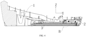
FIG. 4 is a cross-sectional view of a telescopic support leg locking structure with a secondary lock being unlocked according to an embodiment of the present disclosure. -
FIG. 5 is an enlarged view of part B inFIG. 4 . -
FIG. 6 is a cross-sectional view of a telescopic support leg locking structure with a secondary lock being just moved to a position of a locking hole according to an embodiment of the present disclosure. -
FIG. 7 is a cross-sectional view of a telescopic support leg locking structure with a secondary lock being locked with a locking hole according to an embodiment of the present disclosure. -
FIG. 8 is a cross-sectional view of a telescopic support leg locking structure with a secondary lock being locked with a locking hole and a support leg being fully unfolded according to an embodiment of the present disclosure. - List of reference numerals:
1. base; 11. locking hole; 12. first rail; 13. second rail; 2. support leg pedestal; 21. lower cover; 211. chamber; 2111. lower opening; 2112. baffle plate; 2113. slide rail; 22. sliding column; 23. fastener; 24. fixing plate; 25. upper cover; 3. support leg; 4. secondary lock; 41. locking tongue; 411. locking portion; 412. sliding portion; 42. connecting portion; 421. slide groove; 5. connecting rod; 6. restoring spring. - To make the objectives, technical features, and advantages of the present disclosure more comprehensible, specific embodiments of the present disclosure will be described in detail below with reference to the accompanying drawings.
- In the description of the present disclosure, it should be understood that orientation or position relationships indicated by the terms such as "upper" and "lower" are orientation or position relationships based on the normal use of the product.
- The terms "first" and "second" are used herein for descriptive purposes, and are not intended to indicate or imply relative importance or implicitly point out the number of the indicated technical features. Therefore, the feature defined by "first" or "second" may explicitly or implicitly include at least one such feature. In the drawings of the embodiments of the present disclosure, a coordinate system XYZ is provided, where the positive direction of the X axis represents left, the negative direction of the X axis represents right, the positive direction of the Y axis represents front, the negative direction of the Y axis represents rear, the positive direction of the Z axis represents up, and the negative direction of the Z axis represents down.
- An embodiment of the present disclosure provides a telescopic support leg locking structure. Referring to
FIG. 1 ,FIG. 2 ,FIG. 3 ,FIG. 4 ,FIG. 6 ,FIG. 7 , andFIG. 8 , the telescopic support leg locking structure includes abase 1, asupport leg pedestal 2, and asupport leg 3. Thesupport leg pedestal 2 is slidably connected to thebase 1. Thesupport leg 3 is hingedly connected to thesupport leg pedestal 2. The telescopic support leg locking structure further includes asecondary lock 4. Thesupport leg pedestal 2 is provided with achamber 211 for thesecondary lock 4 to slide vertically. Thesecondary lock 4 includes a lockingtongue 41 configured to abut against thesupport leg 3. Thechamber 211 is provided with alower opening 2111 for the lockingtongue 41 to extend out therethrough. Thebase 1 is provided with a lockinghole 11. When thesupport leg 3 is separated from the lockingtongue 41, the lockingtongue 41 is locked with the lockinghole 11 to restrict thesupport leg pedestal 2 from moving forward and backward relative to thebase 1. - The
support leg pedestal 2 can move forward and backward relative to thebase 1. An upper end of thesupport leg 3 is hingedly connected to a front end of thesupport leg pedestal 2. When thesupport leg 3 abuts against the lockingtongue 41, the lockingtongue 41 is pushed upward, i.e., thesecondary lock 4 is moved upward in thechamber 211. After thesecondary lock 4 is moved upward by a distance, the lockingtongue 41 is unlocked from the lockinghole 11, and thesecondary lock 4 can move in a front-rear direction along with thesupport leg pedestal 2. During vertical movement, the lockingtongue 41 always remains in a state of protruding out of thelower opening 2111. When thesupport leg 3 is separated from the lockingtongue 41, a length by which the lockingtongue 41 protrudes from thelower opening 2111 reaches a maximum value, to ensure that the lockingtongue 41 can be locked with the lockinghole 11, thereby preventing thesupport leg pedestal 2 from moving forward and backward relative to thebase 1. That thesupport leg 3 is separated from the lockingtongue 41 means a state in which thesupport leg 3 is rotated to unfold relative to thesupport leg pedestal 2. When the lockingtongue 41 is locked with the lockinghole 11, a position of thelower opening 2111 corresponds to a position of the lockinghole 11. - According to the telescopic support leg locking structure of this embodiment, the
secondary lock 4 configured to lock thesupport leg 3 in an unfolded state with thebase 1 is arranged, and the lockingtongue 41 of thesecondary lock 4 can be unlocked from the lockinghole 11 of thebase 1 and locked with the lockinghole 11 of thebase 1 by folding and unfolding thesupport leg 3, respectively. Such a structure is simple and is convenient and reliable to operate, and ensures that thesupport leg 3 in the unfolded state can remain in the state of being locked with thebase 1. Therefore, thesupport leg 3 can be prevented from retracting when a vehicle accident occurs, thereby ensuring that thesupport leg 3 can effectively support a child safety seat and greatly improving the safety in use. - Optionally, as shown in
FIG. 1 ,FIG. 2 ,FIG. 4 , andFIG. 5 , thebase 1 is provided with afirst rail 12 for thesupport leg pedestal 2 to slide forward and backward, and a slidingcolumn 22 configured to engage with thefirst rail 12 is arranged on thesupport leg pedestal 2. - A length direction of the
first rail 12 is consistent with the front-rear direction. The slidingcolumn 22 is arranged at a rear end of thesupport leg pedestal 2. Asupport leg 3 is hingedly connected to a front end of thesupport leg pedestal 2. When the slidingcolumn 22 moves to a rearmost end of thefirst rail 12, thesupport leg 3 is in a folded state (as shown inFIG. 4 ). When the slidingcolumn 22 moves to a front-most end of thefirst rail 12, thesupport leg 3 is in the unfolded state (as shown inFIG. 8 ). When thesupport leg 3 abuts against the lockingtongue 41, the lockingtongue 41 is pushed upward, and the lockingtongue 41 can be moved into or out of the lockinghole 11 in the front-rear direction. A rear side of the lockinghole 11 is in communication with one end of thefirst rail 12 of thebase 1. When thesupport leg 3 is folded, the lockingtongue 41 can be moved into thefirst rail 12. - In this embodiment, with the design of the sliding
column 22 and thefirst rail 12 that are slidably connected to each other, the slidable connection between thesupport leg pedestal 2 and thebase 1 in the front-rear direction is realized, and thesupport leg pedestal 2 will not tilt during the sliding process. - Optionally, as shown in
FIG. 4 andFIG. 5 , the slidingcolumn 22 is connected to afastener 23 configured to prevent the slidingcolumn 22 from disengaging from thefirst rail 12. - The
fastener 23 is configured to limit the vertical movement of the slidingcolumn 22 relative to thefirst rail 12, i.e., prevent thesupport leg pedestal 2 from moving vertically relative to thebase 1. Thefastener 23 is preferably a screw having a threaded rod and a screw cap. A diameter of the screw cap is greater than a width of thefirst rail 12 in a left-right direction. The screw cap is located below thefirst rail 12. The threaded rod extends through thefirst rail 12 and is fixedly connected to the slidingcolumn 22. - Optionally, as shown in
FIG. 1 ,FIG. 4 ,FIG. 6 ,FIG. 7 , andFIG. 8 , a front end of thefirst rail 12 is in communication with the lockinghole 11, so that after the lockingtongue 41 is unlocked from the lockinghole 11, thesecondary lock 4 can move synchronously with thesupport leg pedestal 2. This ensures that thesupport leg 3 and thesupport leg pedestal 2 can be smoothly moved forward and backward relative to thebase 1, thereby realizing the switching between the folded state and the unfolded state of thesupport leg 3. - Optionally, as shown in
FIG. 1 ,FIG. 2 ,FIG. 3 ,FIG. 4 ,FIG. 6 ,FIG. 7 , andFIG. 8 , the lockingtongue 41 includes a lockingportion 411 and a slidingportion 412 connected to a lower end of the lockingportion 411, the lockingportion 411 is engaged with the lockinghole 11 when the lockingtongue 41 is locked with the lockinghole 11, and the slidingportion 412 is configured to be slidably connected to thefirst rail 12 when the lockingtongue 41 is unlocked from the lockinghole 11. - A width of the locking
portion 411 in the left-right direction is greater than a width of the slidingportion 412 in the left-right direction, so that the lockingtongue 41 is locked with the lockinghole 11 when the lockingportion 411 is engaged with the lockinghole 11, and the lockingtongue 41 is unlocked from the lockinghole 11 when the slidingportion 412 is engaged with the lockinghole 11. The width of the lockingportion 411 in the left-right direction is greater than a width of thefirst rail 12 in the left-right direction, so that when the lockingtongue 41 is locked with the lockinghole 11, thesupport leg 3 is prevented from retracting when impacted by an external force. The width of theslide portion 412 in the left-right direction is less than the width of thefirst rail 12 in the left-right direction, so that thesupport leg pedestal 2 can move forward and backward relative to thebase 1 when thesupport leg 3 is retracted. - In this embodiment, the design of the locking
tongue 41 as two structures, i.e., the lockingportion 411 and the slidingportion 412, not only ensures that the lockingtongue 41 is locked with the lockinghole 11 when thesupport leg 3 is retracted, but also ensures that the lockingtongue 41 can be unlocked smoothly from the lockinghole 11 when thesupport leg 3 is folded, without affecting the forward and backward movement of thesupport leg pedestal 2 relative to thebase 1. - Optionally, as shown in
FIG. 1 ,FIG. 2 , andFIG. 5 , the telescopic support leg locking structure further includes a connectingrod 5 extending through thesupport leg pedestal 2, and thebase 1 is provided with asecond rail 13 configured to engage with the connectingrod 5. - The connecting
rod 5 is of a smooth cylindrical structure, and during the forward and backward movement process, thesupport leg pedestal 2 can drive the connectingrod 5 to move synchronously in thesecond rail 13. In this way, thesupport leg pedestal 2 can stably move forward and backward relative to thebase 1. - Optionally, as shown in
FIG. 2 ,FIG. 3 , andFIG. 5 , thesupport leg pedestal 2 includes alower cover 21 and a fixingplate 24 connected to each other, thechamber 211 is arranged on thelower cover 21, and a restoringspring 6 is arranged between thesecondary lock 4 and the fixingplate 24. - The
secondary lock 4 is provided with a mounting hole for arranging one end of the restoringspring 6. An upper end of the restoringspring 6 abuts against the fixingplate 24. When thesupport leg 3 is unfolded, the restoringspring 6 pushes thesecondary lock 4 to move downward in a timely manner. Thesupport leg pedestal 2 further includes anupper cover 25. The fixingplate 24 is arranged between theupper cover 25 and thelower cover 21. Theupper cover 25 and thelower cover 21 are fixedly connected to each other by a fastener. Thelower cover 21 is preferably made of plastic, and the fixingplate 24 is preferably made of metal, to minimize the overall weight of the child safety seat while ensuring the deformation resistance of thesupport leg pedestal 2. - Optionally, as shown in
FIG. 3 , a connectingportion 42 is arranged at a top of thesecondary lock 4, and abaffle plate 2112 configured to engage with the connectingportion 42 is arranged at thelower opening 2111. - The
secondary lock 4 moves downward rapidly under an elastic force of the restoringspring 6, so that the connectingportion 42 strikes thebaffle plate 2112 and makes a clicking sound, indicating that the secondary lock has been mounted in place. The arrangement of thebaffle plate 2112 can also prevent thesecondary lock 4 from being disengaged from thechamber 211. - Optionally, as shown in
FIG. 3 , a plurality ofslide grooves 421 are provided in a circumferential direction of the connectingportion 42, andslide rails 2113 configured to slidably engage with theslide grooves 421 are correspondingly arranged on an inner wall of thechamber 211. - Four
slide grooves 421 are provided, the fourslide grooves 421 are symmetrically arranged, and correspondingly fourslide rails 2113 are also provided. In this embodiment, the structure in which theslide grooves 421 and theslide rails 2113 are engaged with each other is designed between the connectingportion 42 and thechamber 211, so that the lockingtongue 41 can move straight up and down, thereby ensuring the stability and reliability of the locking function of thesecondary lock 4. - As shown in
FIG. 8 , when thesupport leg 3 is pulled to the outermost position, the restoringspring 6 is engaged into the lockinghole 11 to lock thesecondary lock 4, so that thesupport leg 3 cannot move forward and backward. When a vehicle accident occurs, thesupport leg 3 can be well controlled to support the child safety seat to protect the child in the child safety seat, i.e., thesupport leg 3 is restricted from telescoping forward and backward freely. - As shown in
FIG. 7 ,FIG. 6 , andFIG. 4 , when thesupport leg 3 needs to be retracted, thesupport leg 3 is first folded backward to a certain angle, so that thesupport leg 3 abuts against thesecondary lock 4. Thesupport leg 3 is continuously folded backward. In this case, thesecondary lock 4 is under the compression of thesupport leg 3, and the lockingportion 411 of thesecondary lock 4 has been disengaged from the lockinghole 11, so that thesupport leg 3 can be moved backward and retracted. - Another embodiment of the present disclosure provides a child safety seat, including the telescopic support leg locking structure as described above.
- According to the child safety seat of this embodiment, the
secondary lock 4 configured to lock thesupport leg 3 in an unfolded state with thebase 1 is arranged, and the lockingtongue 41 of thesecondary lock 4 can be unlocked from the lockinghole 11 of thebase 1 and locked with the lockinghole 11 of thebase 1 by folding and unfolding thesupport leg 3, respectively. Such a structure is simple and is convenient and reliable to operate, and ensures that thesupport leg 3 in the unfolded state can remain in the state of being locked with thebase 1. Therefore, thesupport leg 3 can be prevented from retracting when a vehicle accident occurs, thereby ensuring that thesupport leg 3 can effectively support a child safety seat and greatly improving the safety in use. - Although the present disclosure has been disclosed above, the scope of protection of the present disclosure is not limited thereto. Those skilled in the art can make various changes and modifications without departing from the spirit and scope of the present disclosure. Such changes and modifications also fall within the scope of protection of the present disclosure.
Claims (10)
- A telescopic support leg locking structure, comprising a base (1), a support leg pedestal (2), and a support leg (3), wherein the support leg pedestal (2) is slidably connected to the base (1), and the support leg (3) is hingedly connected to the support leg pedestal (2); and the telescopic support leg locking structure further comprises a secondary lock (4), wherein the support leg pedestal (2) is provided with a chamber (211) for the secondary lock (4) to slide vertically, the secondary lock (4) comprises a locking tongue (41) configured to abut against the support leg (3), the chamber (211) is provided with a lower opening (2111) for the locking tongue (41) to extend out therethrough, the base (1) is provided with a locking hole (11), and when the support leg (3) is separated from the locking tongue (41), the locking tongue (41) is locked with the locking hole (11) to restrict the support leg pedestal (2) from moving forward and backward relative to the base (1).
- The telescopic support leg locking structure according to claim 1, wherein the base (1) is provided with a first rail (12) for the support leg pedestal (2) to slide forward and backward, and a sliding column (22) configured to engage with the first rail (12) is arranged on the support leg pedestal (2).
- The telescopic support leg locking structure according to claim 2, wherein the sliding column (22) is connected to a fastener (23) configured to prevent the sliding column (22) from disengaging from the first rail (12).
- The telescopic support leg locking structure according to claim 2, wherein a front end of the first rail (12) is in communication with the locking hole (11).
- The telescopic support leg locking structure according to claim 4, wherein the locking tongue (41) comprises a locking portion (411) and a sliding portion (412) connected to a lower end of the locking portion (411), the locking portion (411) is engaged with the locking hole (11) when the locking tongue (41) is locked with the locking hole (11), and the sliding portion (412) is configured to be slidably connected to the first rail (12) when the locking tongue (41) is unlocked from the locking hole (11).
- The telescopic support leg locking structure according to claim 1, further comprising a connecting rod (5) extending through the support leg pedestal (2), wherein the base (1) is provided with a second rail (13) configured to engage with the connecting rod (5).
- The telescopic support leg locking structure according to claim 1, wherein the support leg pedestal (2) comprises a lower cover (21) and a fixing plate (24) connected to each other, the chamber (211) is arranged on the lower cover (21), and a restoring spring (6) is arranged between the secondary lock (4) and the fixing plate (24).
- The telescopic support leg locking structure according to any one of claims 1-7, wherein a connecting portion (42) is arranged at a top of the secondary lock (4), and a baffle plate (2112) configured to engage with the connecting portion (42) is arranged at the lower opening (2111).
- The telescopic support leg locking structure according to claim 8, wherein a plurality of slide grooves (421) are provided in a circumferential direction of the connecting portion (42), and slide rails (2113) configured to slidably engage with the slide grooves (421) are correspondingly arranged on an inner wall of the chamber (211).
- A child safety seat, comprising the telescopic support leg locking structure according to any one of claims 1-9.
Applications Claiming Priority (2)
| Application Number | Priority Date | Filing Date | Title |
|---|---|---|---|
| CN202121762804.7U CN215621544U (en) | 2021-07-30 | 2021-07-30 | Supporting leg telescopic locking structure and child safety seat |
| PCT/CN2022/101082 WO2023005534A1 (en) | 2021-07-30 | 2022-06-24 | Supporting leg telescopic locking structure and child safety seat |
Publications (4)
| Publication Number | Publication Date |
|---|---|
| EP4328084A1 true EP4328084A1 (en) | 2024-02-28 |
| EP4328084A4 EP4328084A4 (en) | 2024-11-06 |
| EP4328084B1 EP4328084B1 (en) | 2025-08-13 |
| EP4328084C0 EP4328084C0 (en) | 2025-08-13 |
Family
ID=79893718
Family Applications (1)
| Application Number | Title | Priority Date | Filing Date |
|---|---|---|---|
| EP22848141.2A Active EP4328084B1 (en) | 2021-07-30 | 2022-06-24 | Supporting leg telescopic locking structure and child safety seat |
Country Status (3)
| Country | Link |
|---|---|
| EP (1) | EP4328084B1 (en) |
| CN (1) | CN215621544U (en) |
| WO (1) | WO2023005534A1 (en) |
Families Citing this family (4)
| Publication number | Priority date | Publication date | Assignee | Title |
|---|---|---|---|---|
| CN215621545U (en) * | 2021-07-30 | 2022-01-25 | 宁波宝贝第一母婴用品有限公司 | Supporting leg extending structure and child safety seat |
| CN215621544U (en) * | 2021-07-30 | 2022-01-25 | 宁波宝贝第一母婴用品有限公司 | Supporting leg telescopic locking structure and child safety seat |
| CN116834624A (en) * | 2023-08-15 | 2023-10-03 | 布童安全科技(宁波)有限公司 | Rotatable supporting leg and safety seat |
| CN220764159U (en) * | 2023-09-11 | 2024-04-12 | 宁波宝贝第一母婴用品有限公司 | Supporting leg structure and child safety seat |
Family Cites Families (11)
| Publication number | Priority date | Publication date | Assignee | Title |
|---|---|---|---|---|
| CN202071722U (en) * | 2011-04-26 | 2011-12-14 | 中山市隆成日用制品有限公司 | Support frame warning device for safety seat base |
| DE202013011961U1 (en) * | 2013-07-12 | 2014-12-01 | Recaro Child Safety Gmbh & Co. Kg | Base for mounting a child safety seat on a vehicle seat |
| CN107791904B (en) * | 2016-09-05 | 2024-07-02 | 珠海弘点科技有限公司 | Child safety seat support |
| CN206217690U (en) * | 2016-11-25 | 2017-06-06 | gb有限公司 | The supporting leg of child safety seat, pedestal and child safety seat |
| CN210212127U (en) * | 2019-06-27 | 2020-03-31 | 宁波宝贝第一母婴用品有限公司 | Automatic children's safety seat supporting leg of locking |
| CN110281821A (en) * | 2019-06-27 | 2019-09-27 | 宁波宝贝第一母婴用品有限公司 | An automatic locking child safety seat support leg and its folding method |
| CN211892932U (en) * | 2019-12-13 | 2020-11-10 | 宁波妈咪宝婴童用品制造有限公司 | Children car safety seat base |
| CN211731131U (en) * | 2019-12-13 | 2020-10-23 | 宁波优宝儿童用品有限公司 | Child safety seat with supporting legs |
| CN212243053U (en) * | 2020-03-16 | 2020-12-29 | 广东乐美达集团有限公司 | Two-way lock mechanism of child safety seat and child safety seat |
| CN213292068U (en) * | 2020-08-03 | 2021-05-28 | 好孩子儿童用品有限公司 | Supporting device for children articles and children safety seat |
| CN215621544U (en) * | 2021-07-30 | 2022-01-25 | 宁波宝贝第一母婴用品有限公司 | Supporting leg telescopic locking structure and child safety seat |
-
2021
- 2021-07-30 CN CN202121762804.7U patent/CN215621544U/en active Active
-
2022
- 2022-06-24 WO PCT/CN2022/101082 patent/WO2023005534A1/en not_active Ceased
- 2022-06-24 EP EP22848141.2A patent/EP4328084B1/en active Active
Also Published As
| Publication number | Publication date |
|---|---|
| EP4328084B1 (en) | 2025-08-13 |
| EP4328084C0 (en) | 2025-08-13 |
| WO2023005534A1 (en) | 2023-02-02 |
| CN215621544U (en) | 2022-01-25 |
| EP4328084A4 (en) | 2024-11-06 |
Similar Documents
| Publication | Publication Date | Title |
|---|---|---|
| EP4328084A1 (en) | Supporting leg telescopic locking structure and child safety seat | |
| EP3878685B1 (en) | Child safety seat | |
| US8061777B2 (en) | System for seat-actuated head rest extension and retraction | |
| US9022472B2 (en) | Child safety seat | |
| CN118418858A (en) | Child safety seat and side-impact protection mechanism thereof | |
| US9463725B2 (en) | Comfort headrest | |
| CN112519646A (en) | Infant safety seat and unlocking actuator | |
| EP4559778A1 (en) | Vertical-bar connection assembly for collapsible wagon, and collapsible wagon | |
| GB2489822A (en) | Support device for child safety seat | |
| US10953810B2 (en) | Impact bracket stress-deformation release mechanism | |
| CN220842287U (en) | A support leg anti-forgetting structure and child safety seat | |
| EP4410634A1 (en) | Baby stroller capable of implementing free switching between single seat and double seats | |
| CN220764159U (en) | Supporting leg structure and child safety seat | |
| EP4328085A1 (en) | Supporting leg telescopic structure and child safety seat | |
| EP4650216A1 (en) | Safety seat | |
| CN219668018U (en) | Supporting leg assembly of child safety seat | |
| CN107839554A (en) | Children's seat leg structure and children's seat support base | |
| CN215621905U (en) | Landing leg locking device and engineering machinery | |
| EP4347352B1 (en) | Differential energy absorbing steering column | |
| CN223735906U (en) | Small table plate with front-back adjusting mechanism for vehicle and vehicle | |
| CN216761551U (en) | Headrest release mechanism and car seat | |
| CN223618606U (en) | Multi-mode safety belt selection control mechanism and multi-mode safety belt child seat | |
| CN222091201U (en) | A telescopic and adjustable chair leg structure | |
| CN222091189U (en) | Chair seat | |
| CN224013433U (en) | Child safety seats and their bases |
Legal Events
| Date | Code | Title | Description |
|---|---|---|---|
| STAA | Information on the status of an ep patent application or granted ep patent |
Free format text: STATUS: THE INTERNATIONAL PUBLICATION HAS BEEN MADE |
|
| PUAI | Public reference made under article 153(3) epc to a published international application that has entered the european phase |
Free format text: ORIGINAL CODE: 0009012 |
|
| STAA | Information on the status of an ep patent application or granted ep patent |
Free format text: STATUS: REQUEST FOR EXAMINATION WAS MADE |
|
| 17P | Request for examination filed |
Effective date: 20231121 |
|
| AK | Designated contracting states |
Kind code of ref document: A1 Designated state(s): AL AT BE BG CH CY CZ DE DK EE ES FI FR GB GR HR HU IE IS IT LI LT LU LV MC MK MT NL NO PL PT RO RS SE SI SK SM TR |
|
| A4 | Supplementary search report drawn up and despatched |
Effective date: 20241008 |
|
| DAV | Request for validation of the european patent (deleted) | ||
| DAX | Request for extension of the european patent (deleted) | ||
| RIC1 | Information provided on ipc code assigned before grant |
Ipc: B60N 2/28 20060101AFI20241001BHEP |
|
| GRAP | Despatch of communication of intention to grant a patent |
Free format text: ORIGINAL CODE: EPIDOSNIGR1 |
|
| STAA | Information on the status of an ep patent application or granted ep patent |
Free format text: STATUS: GRANT OF PATENT IS INTENDED |
|
| INTG | Intention to grant announced |
Effective date: 20250305 |
|
| GRAS | Grant fee paid |
Free format text: ORIGINAL CODE: EPIDOSNIGR3 |
|
| GRAA | (expected) grant |
Free format text: ORIGINAL CODE: 0009210 |
|
| STAA | Information on the status of an ep patent application or granted ep patent |
Free format text: STATUS: THE PATENT HAS BEEN GRANTED |
|
| AK | Designated contracting states |
Kind code of ref document: B1 Designated state(s): AL AT BE BG CH CY CZ DE DK EE ES FI FR GB GR HR HU IE IS IT LI LT LU LV MC MK MT NL NO PL PT RO RS SE SI SK SM TR |
|
| REG | Reference to a national code |
Ref country code: GB Ref legal event code: FG4D |
|
| REG | Reference to a national code |
Ref country code: CH Ref legal event code: EP |
|
| REG | Reference to a national code |
Ref country code: DE Ref legal event code: R096 Ref document number: 602022019582 Country of ref document: DE |
|
| REG | Reference to a national code |
Ref country code: IE Ref legal event code: FG4D |
|
| U01 | Request for unitary effect filed |
Effective date: 20250911 |
|
| U07 | Unitary effect registered |
Designated state(s): AT BE BG DE DK EE FI FR IT LT LU LV MT NL PT RO SE SI Effective date: 20250917 |
|
| U1N | Appointed representative for the unitary patent procedure changed after the registration of the unitary effect |
Representative=s name: LORENZ SEIDLER GOSSEL PART. MBB; DE |
|
| PG25 | Lapsed in a contracting state [announced via postgrant information from national office to epo] |
Ref country code: IS Free format text: LAPSE BECAUSE OF FAILURE TO SUBMIT A TRANSLATION OF THE DESCRIPTION OR TO PAY THE FEE WITHIN THE PRESCRIBED TIME-LIMIT Effective date: 20251213 |
|
| PG25 | Lapsed in a contracting state [announced via postgrant information from national office to epo] |
Ref country code: NO Free format text: LAPSE BECAUSE OF FAILURE TO SUBMIT A TRANSLATION OF THE DESCRIPTION OR TO PAY THE FEE WITHIN THE PRESCRIBED TIME-LIMIT Effective date: 20251113 |
|
| PG25 | Lapsed in a contracting state [announced via postgrant information from national office to epo] |
Ref country code: HR Free format text: LAPSE BECAUSE OF FAILURE TO SUBMIT A TRANSLATION OF THE DESCRIPTION OR TO PAY THE FEE WITHIN THE PRESCRIBED TIME-LIMIT Effective date: 20250813 |
|
| PG25 | Lapsed in a contracting state [announced via postgrant information from national office to epo] |
Ref country code: GR Free format text: LAPSE BECAUSE OF FAILURE TO SUBMIT A TRANSLATION OF THE DESCRIPTION OR TO PAY THE FEE WITHIN THE PRESCRIBED TIME-LIMIT Effective date: 20251114 |
|
| PG25 | Lapsed in a contracting state [announced via postgrant information from national office to epo] |
Ref country code: PL Free format text: LAPSE BECAUSE OF FAILURE TO SUBMIT A TRANSLATION OF THE DESCRIPTION OR TO PAY THE FEE WITHIN THE PRESCRIBED TIME-LIMIT Effective date: 20250813 |
|
| PG25 | Lapsed in a contracting state [announced via postgrant information from national office to epo] |
Ref country code: RS Free format text: LAPSE BECAUSE OF FAILURE TO SUBMIT A TRANSLATION OF THE DESCRIPTION OR TO PAY THE FEE WITHIN THE PRESCRIBED TIME-LIMIT Effective date: 20251113 |
|
| PG25 | Lapsed in a contracting state [announced via postgrant information from national office to epo] |
Ref country code: ES Free format text: LAPSE BECAUSE OF FAILURE TO SUBMIT A TRANSLATION OF THE DESCRIPTION OR TO PAY THE FEE WITHIN THE PRESCRIBED TIME-LIMIT Effective date: 20250813 |
|
| PG25 | Lapsed in a contracting state [announced via postgrant information from national office to epo] |
Ref country code: SM Free format text: LAPSE BECAUSE OF FAILURE TO SUBMIT A TRANSLATION OF THE DESCRIPTION OR TO PAY THE FEE WITHIN THE PRESCRIBED TIME-LIMIT Effective date: 20250813 |
|
| PG25 | Lapsed in a contracting state [announced via postgrant information from national office to epo] |
Ref country code: CZ Free format text: LAPSE BECAUSE OF FAILURE TO SUBMIT A TRANSLATION OF THE DESCRIPTION OR TO PAY THE FEE WITHIN THE PRESCRIBED TIME-LIMIT Effective date: 20250813 |
|
| PG25 | Lapsed in a contracting state [announced via postgrant information from national office to epo] |
Ref country code: SK Free format text: LAPSE BECAUSE OF FAILURE TO SUBMIT A TRANSLATION OF THE DESCRIPTION OR TO PAY THE FEE WITHIN THE PRESCRIBED TIME-LIMIT Effective date: 20250813 |