EP4328065A1 - Cover-equipped electronic device - Google Patents
Cover-equipped electronic device Download PDFInfo
- Publication number
- EP4328065A1 EP4328065A1 EP23189722.4A EP23189722A EP4328065A1 EP 4328065 A1 EP4328065 A1 EP 4328065A1 EP 23189722 A EP23189722 A EP 23189722A EP 4328065 A1 EP4328065 A1 EP 4328065A1
- Authority
- EP
- European Patent Office
- Prior art keywords
- cover
- restraining
- device body
- latching
- guide
- Prior art date
- Legal status (The legal status is an assumption and is not a legal conclusion. Google has not performed a legal analysis and makes no representation as to the accuracy of the status listed.)
- Granted
Links
Images






Classifications
-
- B—PERFORMING OPERATIONS; TRANSPORTING
- B60—VEHICLES IN GENERAL
- B60K—ARRANGEMENT OR MOUNTING OF PROPULSION UNITS OR OF TRANSMISSIONS IN VEHICLES; ARRANGEMENT OR MOUNTING OF PLURAL DIVERSE PRIME-MOVERS IN VEHICLES; AUXILIARY DRIVES FOR VEHICLES; INSTRUMENTATION OR DASHBOARDS FOR VEHICLES; ARRANGEMENTS IN CONNECTION WITH COOLING, AIR INTAKE, GAS EXHAUST OR FUEL SUPPLY OF PROPULSION UNITS IN VEHICLES
- B60K35/00—Instruments specially adapted for vehicles; Arrangement of instruments in or on vehicles
- B60K35/20—Output arrangements, i.e. from vehicle to user, associated with vehicle functions or specially adapted therefor
- B60K35/21—Output arrangements, i.e. from vehicle to user, associated with vehicle functions or specially adapted therefor using visual output, e.g. blinking lights or matrix displays
- B60K35/22—Display screens
-
- H—ELECTRICITY
- H05—ELECTRIC TECHNIQUES NOT OTHERWISE PROVIDED FOR
- H05K—PRINTED CIRCUITS; CASINGS OR CONSTRUCTIONAL DETAILS OF ELECTRIC APPARATUS; MANUFACTURE OF ASSEMBLAGES OF ELECTRICAL COMPONENTS
- H05K5/00—Casings, cabinets or drawers for electric apparatus
- H05K5/02—Details
- H05K5/0217—Mechanical details of casings
-
- B—PERFORMING OPERATIONS; TRANSPORTING
- B60—VEHICLES IN GENERAL
- B60K—ARRANGEMENT OR MOUNTING OF PROPULSION UNITS OR OF TRANSMISSIONS IN VEHICLES; ARRANGEMENT OR MOUNTING OF PLURAL DIVERSE PRIME-MOVERS IN VEHICLES; AUXILIARY DRIVES FOR VEHICLES; INSTRUMENTATION OR DASHBOARDS FOR VEHICLES; ARRANGEMENTS IN CONNECTION WITH COOLING, AIR INTAKE, GAS EXHAUST OR FUEL SUPPLY OF PROPULSION UNITS IN VEHICLES
- B60K35/00—Instruments specially adapted for vehicles; Arrangement of instruments in or on vehicles
- B60K35/50—Instruments characterised by their means of attachment to or integration in the vehicle
-
- B—PERFORMING OPERATIONS; TRANSPORTING
- B60—VEHICLES IN GENERAL
- B60R—VEHICLES, VEHICLE FITTINGS, OR VEHICLE PARTS, NOT OTHERWISE PROVIDED FOR
- B60R11/00—Arrangements for holding or mounting articles, not otherwise provided for
- B60R11/02—Arrangements for holding or mounting articles, not otherwise provided for for radio sets, television sets, telephones, or the like; Arrangement of controls thereof
- B60R11/0229—Arrangements for holding or mounting articles, not otherwise provided for for radio sets, television sets, telephones, or the like; Arrangement of controls thereof for displays, e.g. cathodic tubes
-
- H—ELECTRICITY
- H05—ELECTRIC TECHNIQUES NOT OTHERWISE PROVIDED FOR
- H05K—PRINTED CIRCUITS; CASINGS OR CONSTRUCTIONAL DETAILS OF ELECTRIC APPARATUS; MANUFACTURE OF ASSEMBLAGES OF ELECTRICAL COMPONENTS
- H05K5/00—Casings, cabinets or drawers for electric apparatus
- H05K5/0017—Casings, cabinets or drawers for electric apparatus with operator interface units
- H05K5/0018—Casings, cabinets or drawers for electric apparatus with operator interface units having an electronic display
-
- H—ELECTRICITY
- H05—ELECTRIC TECHNIQUES NOT OTHERWISE PROVIDED FOR
- H05K—PRINTED CIRCUITS; CASINGS OR CONSTRUCTIONAL DETAILS OF ELECTRIC APPARATUS; MANUFACTURE OF ASSEMBLAGES OF ELECTRICAL COMPONENTS
- H05K5/00—Casings, cabinets or drawers for electric apparatus
- H05K5/02—Details
- H05K5/0217—Mechanical details of casings
- H05K5/0221—Locks; Latches
-
- H—ELECTRICITY
- H05—ELECTRIC TECHNIQUES NOT OTHERWISE PROVIDED FOR
- H05K—PRINTED CIRCUITS; CASINGS OR CONSTRUCTIONAL DETAILS OF ELECTRIC APPARATUS; MANUFACTURE OF ASSEMBLAGES OF ELECTRICAL COMPONENTS
- H05K5/00—Casings, cabinets or drawers for electric apparatus
- H05K5/02—Details
- H05K5/0217—Mechanical details of casings
- H05K5/0234—Feet; Stands; Pedestals, e.g. wheels for moving casing on floor
-
- H—ELECTRICITY
- H05—ELECTRIC TECHNIQUES NOT OTHERWISE PROVIDED FOR
- H05K—PRINTED CIRCUITS; CASINGS OR CONSTRUCTIONAL DETAILS OF ELECTRIC APPARATUS; MANUFACTURE OF ASSEMBLAGES OF ELECTRICAL COMPONENTS
- H05K5/00—Casings, cabinets or drawers for electric apparatus
- H05K5/02—Details
- H05K5/03—Covers
-
- B—PERFORMING OPERATIONS; TRANSPORTING
- B60—VEHICLES IN GENERAL
- B60K—ARRANGEMENT OR MOUNTING OF PROPULSION UNITS OR OF TRANSMISSIONS IN VEHICLES; ARRANGEMENT OR MOUNTING OF PLURAL DIVERSE PRIME-MOVERS IN VEHICLES; AUXILIARY DRIVES FOR VEHICLES; INSTRUMENTATION OR DASHBOARDS FOR VEHICLES; ARRANGEMENTS IN CONNECTION WITH COOLING, AIR INTAKE, GAS EXHAUST OR FUEL SUPPLY OF PROPULSION UNITS IN VEHICLES
- B60K2360/00—Indexing scheme associated with groups B60K35/00 or B60K37/00 relating to details of instruments or dashboards
- B60K2360/60—Structural details of dashboards or instruments
- B60K2360/68—Features of instruments
- B60K2360/688—Frames or decorative parts
-
- B—PERFORMING OPERATIONS; TRANSPORTING
- B60—VEHICLES IN GENERAL
- B60K—ARRANGEMENT OR MOUNTING OF PROPULSION UNITS OR OF TRANSMISSIONS IN VEHICLES; ARRANGEMENT OR MOUNTING OF PLURAL DIVERSE PRIME-MOVERS IN VEHICLES; AUXILIARY DRIVES FOR VEHICLES; INSTRUMENTATION OR DASHBOARDS FOR VEHICLES; ARRANGEMENTS IN CONNECTION WITH COOLING, AIR INTAKE, GAS EXHAUST OR FUEL SUPPLY OF PROPULSION UNITS IN VEHICLES
- B60K2360/00—Indexing scheme associated with groups B60K35/00 or B60K37/00 relating to details of instruments or dashboards
- B60K2360/60—Structural details of dashboards or instruments
- B60K2360/68—Features of instruments
- B60K2360/691—Housings
-
- B—PERFORMING OPERATIONS; TRANSPORTING
- B60—VEHICLES IN GENERAL
- B60K—ARRANGEMENT OR MOUNTING OF PROPULSION UNITS OR OF TRANSMISSIONS IN VEHICLES; ARRANGEMENT OR MOUNTING OF PLURAL DIVERSE PRIME-MOVERS IN VEHICLES; AUXILIARY DRIVES FOR VEHICLES; INSTRUMENTATION OR DASHBOARDS FOR VEHICLES; ARRANGEMENTS IN CONNECTION WITH COOLING, AIR INTAKE, GAS EXHAUST OR FUEL SUPPLY OF PROPULSION UNITS IN VEHICLES
- B60K2360/00—Indexing scheme associated with groups B60K35/00 or B60K37/00 relating to details of instruments or dashboards
- B60K2360/77—Instrument locations other than the dashboard
- B60K2360/771—Instrument locations other than the dashboard on the ceiling
-
- B—PERFORMING OPERATIONS; TRANSPORTING
- B60—VEHICLES IN GENERAL
- B60K—ARRANGEMENT OR MOUNTING OF PROPULSION UNITS OR OF TRANSMISSIONS IN VEHICLES; ARRANGEMENT OR MOUNTING OF PLURAL DIVERSE PRIME-MOVERS IN VEHICLES; AUXILIARY DRIVES FOR VEHICLES; INSTRUMENTATION OR DASHBOARDS FOR VEHICLES; ARRANGEMENTS IN CONNECTION WITH COOLING, AIR INTAKE, GAS EXHAUST OR FUEL SUPPLY OF PROPULSION UNITS IN VEHICLES
- B60K2360/00—Indexing scheme associated with groups B60K35/00 or B60K37/00 relating to details of instruments or dashboards
- B60K2360/84—Mounting of dashboard components
-
- B—PERFORMING OPERATIONS; TRANSPORTING
- B60—VEHICLES IN GENERAL
- B60K—ARRANGEMENT OR MOUNTING OF PROPULSION UNITS OR OF TRANSMISSIONS IN VEHICLES; ARRANGEMENT OR MOUNTING OF PLURAL DIVERSE PRIME-MOVERS IN VEHICLES; AUXILIARY DRIVES FOR VEHICLES; INSTRUMENTATION OR DASHBOARDS FOR VEHICLES; ARRANGEMENTS IN CONNECTION WITH COOLING, AIR INTAKE, GAS EXHAUST OR FUEL SUPPLY OF PROPULSION UNITS IN VEHICLES
- B60K35/00—Instruments specially adapted for vehicles; Arrangement of instruments in or on vehicles
-
- B—PERFORMING OPERATIONS; TRANSPORTING
- B60—VEHICLES IN GENERAL
- B60K—ARRANGEMENT OR MOUNTING OF PROPULSION UNITS OR OF TRANSMISSIONS IN VEHICLES; ARRANGEMENT OR MOUNTING OF PLURAL DIVERSE PRIME-MOVERS IN VEHICLES; AUXILIARY DRIVES FOR VEHICLES; INSTRUMENTATION OR DASHBOARDS FOR VEHICLES; ARRANGEMENTS IN CONNECTION WITH COOLING, AIR INTAKE, GAS EXHAUST OR FUEL SUPPLY OF PROPULSION UNITS IN VEHICLES
- B60K35/00—Instruments specially adapted for vehicles; Arrangement of instruments in or on vehicles
- B60K35/60—Instruments characterised by their location or relative disposition in or on vehicles
-
- B—PERFORMING OPERATIONS; TRANSPORTING
- B60—VEHICLES IN GENERAL
- B60R—VEHICLES, VEHICLE FITTINGS, OR VEHICLE PARTS, NOT OTHERWISE PROVIDED FOR
- B60R11/00—Arrangements for holding or mounting articles, not otherwise provided for
- B60R2011/0042—Arrangements for holding or mounting articles, not otherwise provided for characterised by mounting means
- B60R2011/0049—Arrangements for holding or mounting articles, not otherwise provided for characterised by mounting means for non integrated articles
- B60R2011/0064—Connection with the article
- B60R2011/0071—Connection with the article using latches, clips, clamps, straps or the like
-
- G—PHYSICS
- G02—OPTICS
- G02F—OPTICAL DEVICES OR ARRANGEMENTS FOR THE CONTROL OF LIGHT BY MODIFICATION OF THE OPTICAL PROPERTIES OF THE MEDIA OF THE ELEMENTS INVOLVED THEREIN; NON-LINEAR OPTICS; FREQUENCY-CHANGING OF LIGHT; OPTICAL LOGIC ELEMENTS; OPTICAL ANALOGUE/DIGITAL CONVERTERS
- G02F1/00—Devices or arrangements for the control of the intensity, colour, phase, polarisation or direction of light arriving from an independent light source, e.g. switching, gating or modulating; Non-linear optics
- G02F1/01—Devices or arrangements for the control of the intensity, colour, phase, polarisation or direction of light arriving from an independent light source, e.g. switching, gating or modulating; Non-linear optics for the control of the intensity, phase, polarisation or colour
- G02F1/13—Devices or arrangements for the control of the intensity, colour, phase, polarisation or direction of light arriving from an independent light source, e.g. switching, gating or modulating; Non-linear optics for the control of the intensity, phase, polarisation or colour based on liquid crystals, e.g. single liquid crystal display cells
- G02F1/133—Constructional arrangements; Operation of liquid crystal cells; Circuit arrangements
- G02F1/1333—Constructional arrangements; Manufacturing methods
- G02F1/133308—Support structures for LCD panels, e.g. frames or bezels
Definitions
- the present invention relates to electronic devices having various electronic functions, such as onboard display devices, and particularly relates to an electronic device equipped with a cover that is fastened to a device body by latching onto the device body.
- An electronic-device housing is disclosed by JP 8-130382 A , in which a cover is fastened to a case by latching onto the case.
- the case of this electronic-device housing is open upward and has two pairs of engaging ribs.
- the engaging ribs in each pair are provided on the inner side of opposite walls of the case and are located opposite each other.
- Each engaging rib is an elastic plate having a slide groove.
- the slide groove is open at one end of the engaging rib and is inclined upward, away from the case, toward the open side.
- the case has another engaging rib provided on one-end wall thereof extending orthogonally to the opposite walls. This engaging rib has two holes.
- the cover has two pairs of catches provided on the inner side of opposite walls thereof and in correspondence with the slide grooves. The catches have respective inclined surfaces that are at the same angle as the slide grooves.
- the cover further has two fitting protrusions provided on one-end wall thereof and in correspondence with the above-mentioned holes.
- the fitting protrusions provided on the one-end wall of the cover are fitted into the respective holes provided in the one-end wall of the case, and the cover is rotated about the fitted part where the fitting protrusions are fitted into the holes and in such a manner as to be pushed toward the case.
- the catches of the cover slide along the outer surfaces of the engaging ribs of the case that have the slide grooves.
- the engaging ribs elastically deform to allow the catches to engage with the slide grooves.
- the cover is attached to the case.
- the fitting protrusions on the one-end wall of the cover first need to be positioned relative to the holes in the one-end wall of the case before being fitted into the holes.
- Such a positioning process is annoying.
- the cover is to be attached to the back face of the case and the worker therefore has to attach the cover without directly seeing the positions of the fitting protrusions and the holes, the above positioning and fitting process is particularly difficult.
- An object of the present invention is to provide a cover-equipped electronic device configured such that a cover is easily attachable to a device body and, after the cover is attached to the device body, noise due to wobbling is reduced with a minimized number of points of contact between the device body and the cover.
- the invention relates to a cover-equipped electronic device according to the appended claims. Embodiments are disclosed in the depended claims.
- a cover-equipped electronic device includes:
- One of the device body and the cover has a projecting latch
- an other of the device body and the cover has a receiving hole or a receiving recess that is to receive the projecting latch, the projecting latch being configured to latch into the receiving hole or the receiving recess and make the cover attached to the device body when the cover is moved in a predetermined latching-force-acting direction.
- a restraining guide is provided between the device body and the cover and is configured to allow the cover to move in the latching-force-acting direction while restraining the cover in a direction intersecting the latching-force-acting direction.
- a press-contact guide be provided between the device body and the cover and be configured to cause the device body and the cover to be pressed into contact with each other when the cover is pressed against the device body in the direction intersecting the latching-force-acting direction.
- the restraining guide include
- the restraining guide be configured to guide the cover while further restraining the cover in a horizontal direction that intersects both the vertical direction and the latching-force-acting direction.
- the cover-equipped electronic device according to the present invention may be configured as follows.
- the restraining guide has a restraining oblong hole and a restraining projection, the restraining oblong hole being provided in one of the cover and the device body, the restraining projection being provided on an other of the cover and the device body, the restraining oblong hole being elongated in the latching-force-acting direction.
- the restraining projection may be configured to move in the restraining oblong hole such that the cover is guided in the latching-force-acting direction while being restrained in a vertical direction from moving away from the device body and while being further restrained in a horizontal direction that intersects both the vertical direction and the latching-force-acting direction.
- a press-contact guide be provided between the device body and the cover and be configured to cause the device body and the cover to be pressed into contact with each other when the cover is pressed against the device body in the direction intersecting the latching-force-acting direction to cause the restraining projection to be inserted into an introduction opening that is continuous with the restraining oblong hole.
- the cover-equipped electronic device it is preferable that while the cover is being guided in the latching-force-acting direction with the restraining projection moving in the restraining oblong hole, the cover be guided to a position close to the device body where the projecting latch faces the receiving hole or the receiving recess to be able to latch into the receiving hole or the receiving recess.
- the projecting latch include
- the device body is to be installed on a ceiling of a cabin of a vehicle and includes a display screen and an attaching mechanism, the display screen being provided at a front face of the device body, the attaching mechanism being provided at a back face of the device body and allowing the device body to be attached to the vehicle, the attaching mechanism being covered by the cover.
- the cover-equipped electronic device to attach the cover to the device body, the cover is simply slid in the latching-force-acting direction while being restrained by the restraining guide.
- the projecting latch is assuredly made to latch into the receiving hole or the receiving recess.
- the press-contact guide is provided between the device body and the cover
- the restraint and guiding by the restraining guide is started by simply pressing the cover into contact with the device body at the press-contact guide and sliding the cover in the latching-force-acting direction.
- the attaching of the cover is further facilitated.
- the cover-equipped electronic device when the projecting latch latches into the receiving hole or the receiving recess and the attaching of the cover to the device body is thus complete, the restraint by the restraining guide is disabled. Therefore, after the completion of the attaching, the cover and the device body are kept out of contact with each other at the restraining guide. Accordingly, noise due to wobbling under external vibrations is reduced.
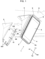
- Fig. 1 illustrates an onboard display device 1, which is an exemplary electronic device according to an embodiment of the present invention.
- the onboard display device 1 includes a device body 2 and a cover 3.
- the cover 3 is attached to the back face, 2b, of the device body 2.
- the device body 2 includes a housing 4, in which a display unit and an electronic circuit are housed.
- the display unit has a display screen 5, which is exposed at the front face, 2a, of the device body 2.
- the display unit includes display elements such as liquid-crystal display elements or electroluminescent elements.
- the onboard display device 1 illustrated in Fig. 1 maybe installed on the ceiling, 6, of the vehicle cabin of an automobile and is viewed obliquely from the lower front.
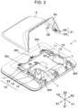
- the device body 2 is illustrated in an orientation in which the front face 2a thereof extends horizontally in the drawings, for visibility of relevant structures at the back face 2b of the device body 2 and the process of attaching the cover 3 to the device body 2.
- the orientation of the onboard display device 1 is defined as follows.
- the Y1-Y2 direction represents the top-bottom direction with respect to the front face 2a of the device body 2, with the Y1 direction representing the upward direction and the Y2 direction representing the downward direction.
- the Y1 direction is also referred to as "latching-force-acting direction" in describing the process of attaching the cover 3 to the device body 2.
- the X1-X2 direction represents the left-right direction with respect to the front face 2a of the device body 2, with the X1 direction representing the leftward direction and the X2 direction representing the rightward direction.
- the X1-X2 direction is also referred to as "horizontal direction” in describing the process of attaching the cover 3 to the device body 2.
- the Z1-Z2 direction defined in Fig. 2 and others represents the front-rear direction with respect to the front face 2a of the device body 2, with the Z1 direction representing the frontward direction and the Z2 direction representing the rearward direction (the direction toward the back face 2b).
- the Z1-Z2 direction is also referred to as "vertical direction” in describing the process of attaching the cover 3 to the device body 2.
- the Z1 direction is also referred to as "approaching direction”; that is, contacting direction or pressing direction, in which the cover 3 is attached to the device body 2.
- the Z2 direction is also referred to as "retreating direction", in which the cover 3 goes away from the device body 2.
- the device body 2 is provided with attaching mechanisms 7 on the left and right sides of the back face 2a thereof.
- the ceiling 6 of the vehicle cabin has an opening 8, in which a supporting mechanism 9 is fixedly provided.
- the attaching mechanisms 7 are coupled to the supporting mechanism 9, the device body 2 is fastened to the ceiling 6 in such a manner as to hang from the ceiling 6.
- the cover 3 is fastened to the back face 2b of the device body 2, whereby the points of coupling between the attaching mechanisms 7 and the supporting mechanism 9 are covered by the cover 3.
- the device body 2 is set up in an orientation in which the display screen 5 thereof faces obliquely frontward and downward. Guiding mechanisms 10 and latching mechanisms 30f and 30r are provided between the device body 2 and the cover 3 and are therefore unseeable in the process of attaching the cover 3 to the back face 2b of the device body 2. Inevitably, the attaching of the cover 3 to the device body 2 has to be performed by the feel. In view of such a situation, in the onboard display device 1 according to the embodiment of the present invention, the guiding mechanisms 10 and the latching mechanisms 30f and 30r are configured to facilitate the attaching of the cover 3 to the device body 2.
- the onboard display device 1 illustrated in Fig. 2 includes the guiding mechanisms 10 and the latching mechanisms 30f and 30r, which are upper latching mechanisms 30f and lower latching mechanisms 30r, between the device body 2 and the cover 3.
- one guiding mechanism 10 is provided on each of the left and right sides of the device body 2
- two upper latching mechanisms 30f are provided on the upper (Y1) side of the device body 2
- three lower latching mechanisms 30r are provided on the lower (Y2) side of the device body 2.
- each guiding mechanism 10 includes a press-contact guide 10A and a restraining guide 10B.
- the press-contact guide 10A and the restraining guide 10B are formed as part of the device body 2 and the cover 3.
- the press-contact guide 10A is provided at the back face 2b of the device body 2 and includes a first guiding rib 11; a second guiding rib 12, which is located on the Y1 side relative to the first guiding rib 11; and a third guiding rib 13, which is located on the Y1 side relative to the second guiding rib 12.
- the guiding ribs 11, 12, and 13 are formed integrally with the housing 4 of the device body 2 from a material such as synthetic resin or light metal.
- the guiding ribs 11, 12, and 13 stand upright in the retreating direction (Z2 direction) and are elongated in the latching-force-acting direction (Y1 direction).
- the first guiding rib 11 has at the top thereof a first press-contact slide part 11a.
- the second guiding rib 12 has at the top thereof a second press-contact slide part 12a.
- the first press-contact slide part 11a and the second press-contact slide part 12a are at the same height in the Z2 direction from the back face 2b of the device body 2.
- the third guiding rib 13 has at the top thereof a third press-contact slide part 13a and a press-contact-disabling part 13b.
- the press-contact-disabling part 13b is located on the Y1 side relative to the third press-contact slide part 13a and is continuous with the third press-contact slide part 13a but at a different height in the Z2 direction from the back face 2b of the device body 2.
- the third press-contact slide part 13a is at a lower level than the first press-contact slide part 11a and the second press-contact slide part 12a in such a manner as to be retracted therefrom in the approaching direction (Z1 direction) toward the device body 2.
- the press-contact-disabling part 13b is at a lower level than the third press-contact slide part 13a in such a manner as to be retracted therefrom in the approaching direction.
- the cover 3 has, on a side wall 3a thereof, a first press-contact projection 15 and a second press-contact projection 16, which are constituents of the press-contact guide 10A.
- the second press-contact projection 16 is located on the Y1 side relative to the first press-contact projection 15.
- the press-contact projections 15 and 16 are formed integrally with the cover 3 from a material such as synthetic resin or light metal and each extend in the contacting direction (Z1 direction).
- the second press-contact projection 16 is visible, but the first press-contact projection 15 is hidden behind the cover 3.
- FIG 8A illustrates a plane section of the press-contact guide 10A in a state where the first press-contact projection 15 is in contact with the first press-contact slide part 11a of the device body 2, and the second press-contact projection 16 is in contact with the second press-contact slide part 12a.
- the housing 4 has a restraining oblong hole 21.
- the restraining oblong hole 21 extends linearly in the latching-force-acting direction (Y1 direction) with a constant width in the horizontal direction (X1-X2 direction).
- the housing 4 further has an introduction opening 22, which is continuous with the Y2-side end of the restraining oblong hole 21.
- the introduction opening 22 has a greater width in the horizontal direction (X1-X2 direction) than the restraining oblong hole 21.
- an inner end of the introduction opening 22 that is on the forward side (Y1 side) of the latching-force-acting direction serves as a guiding end 22a.
- the guiding end 22a is provided on each of the left side (X1 side) and the right side (X2 side) of the restraining oblong hole 21.
- the two guiding ends 22a are inclined toward each other while extending in the latching-force-acting direction (Y1 direction).
- the housing 4 further has a restraint-disabling opening 23, which is continuous with the Y1-side end of the restraining oblong hole 21.
- the restraint-disabling opening 23 has a greater width in the left-right direction (X1-X2 direction) than the restraining oblong hole 21.
- the introduction opening 22 and the restraint-disabling opening 23 illustrated in Fig. 8A are each a rectangular hole surrounded by the housing 4.
- the openings 22 and 23 may each be a polygonal or circular hole.
- the openings 22 and 23 may each be a notch or a recess provided in the housing 4 and being open on the right side (X2 side) or any other side.
- the housing 4 further has a restraining rib 24, which is a constituent of the restraining guide 10B and is formed integrally with the housing 4 in such a manner as to be raised in the retreating direction (Z2 direction).
- the top of the restraining rib 24 that is on the Z2 side extends in the latching-force-acting direction (Y1 direction).
- the restraining rib 24 includes at the top thereof a rear vertical restraining guide 24a, a rear inclined restraining guide 24b, and a rear approach restraining guide 24c.
- the rear inclined restraining guide 24b is continuous with the Y1-side end of the rear vertical restraining guide 24a.
- the rear approach restraining guide 24c is continuous with the Y1-side end of the rear inclined restraining guide 24b.
- the height of the rear vertical restraining guide 24a from the back face 2b of the housing 4 is constant.
- the height of the rear approach restraining guide 24c from the back face 2b of the housing 4 is also constant.
- the rear approach restraining guide 24c is at a lower level than the rear vertical restraining guide 24a in such a manner as to be retracted therefrom in the approaching direction (Z1 direction).
- the rear inclined restraining guide 24b is inclined toward the back face 2b of the housing 4 while extending in the Y1 direction.
- part of a surface (inner surface) of the housing 4 that faces toward the front side (Z1 side) is also a constituent of the restraining guide 10B.
- the inner surface of the housing 4 forms a front vertical restraining guide 25a, a front inclined restraining guide 25b, and a front approach restraining guide 25c.
- the front inclined restraining guide 25b is continuous with the Y1-side end of the front vertical restraining guide 25a.
- the front approach restraining guide 25c is continuous with the Y1-side end of the front inclined restraining guide 25b.
- the front approach restraining guide 25c is at a lower level than the front vertical restraining guide 25a in such a manner as to be retracted therefrom in the approaching direction (Z1 direction).
- the front inclined restraining guide 25b is inclined toward the inner side (Z1 side) of the housing 4 while extending in the Y1 direction.
- a combination of the rear vertical restraining guide 24a and the front vertical restraining guide 25a serves as "vertical restraining guide”
- a combination of the rear approach restraining guide 24c and the front approach restraining guide 25c serves as "approach restraining guide”.
- the distance between the rear vertical restraining guide 24a and the front vertical restraining guide 25a in the Z1-Z2 direction is equal to the distance between the rear approach restraining guide 24c and the front approach restraining guide 25c in the Z1-Z2 direction.
- the cover 3 has a restraining projection 28, which projects in the approaching direction (Z1 direction) from the side wall 3a and is formed integrally with the cover 3.
- the restraining projection 28 is also a constituent of the restraining guide 10B.
- the restraining projection 28 includes an intercepting part 28a, a rear facing part 28b, and a front facing part 28c.
- the intercepting part 28a has a constant width in the horizontal direction (X1-X2 direction) within a certain area in the vertical direction (Z1-Z2 direction).
- the rear facing part 28b extends from the retreating-side (Z2-side) end of the intercepting part 28a toward the right side (X2 side).
- the front facing part 28c extends from the approaching-side (Z1-side) end of the intercepting part 28a toward the left side (X1 side).
- the intercepting part 28a of the restraining projection 28 is positioned in the restraining oblong hole 21 provided in the housing 4.
- the space for the intercepting part 28a in the restraining oblong hole 21 in the horizontal direction (X1-X2 direction) is small enough to restrain the restraining projection 28 from moving in the horizontal direction.
- the rear facing part 28b of the restraining projection 28 faces the rear vertical restraining guide 24a at the top of the restraining rib 24, and the front facing part 28c faces the front vertical restraining guide 25a at the inner surface of the housing 4.
- the restraining projection 28 and the cover 3 are restrained from moving in the vertical direction (Z1-Z2 direction).
- the rear facing part 28b of the restraining projection 28 faces the rear approach restraining guide 24c at the top of the restraining rib 24, and the front facing part 28c faces the front approach restraining guide 25c at the inner surface of the housing 4.
- the restraining projection 28 and the cover 3 are restrained from moving in the vertical direction (Z1-Z2 direction) at a position lowered in the approaching direction (Z1 direction).
- the device body 2 has the guiding mechanism 10 on the left side (X1 side) as well.
- the configuration of the guiding mechanism 10 provided on the left side and the configuration of the guiding mechanism 10 provided on the right side and described above are in bilateral symmetry in the horizontal direction (X1-X2 direction).
- the configuration of the guiding mechanism 10 may be inverted from the one described in the present embodiment.
- the cover 3 may have the first guiding rib 11, the second guiding rib 12, and the third guiding rib 13, while the device body 2 may have the first press-contact projection 15 and the second press-contact projection 16.
- the cover 3 may have the rear vertical restraining guide 24a, the front vertical restraining guide 25a, the rear approach restraining guide 24c, the front approach restraining guide 25c, the restraining oblong hole 21, and other relevant elements, while the device body 2 may have the restraining projection 28.
- Figs. 3 and 4A each illustrate one of the two upper latching mechanisms 30f.
- Each upper latching mechanism 30f includes a projecting latch 31 and a receiving hole 34.
- the projecting latch 31 is formed integrally with the cover 3.
- the receiving hole 34 is provided in the housing 4 of the device body 2.
- the projecting latch 31 includes a locking projection 32 and a latching projection 33.
- the locking projection 32 includes a vertical locking rib 32a and a horizontal locking rib 32b.
- the vertical locking rib 32a projects in the vertical direction (Z1-Z2 direction) while extending in the latching-force-acting direction (Y1 direction).
- the horizontal locking rib 32b projects in the horizontal direction (X1-X2 direction) while extending in the latching-force-acting direction (Y1 direction).
- the latching projection 33 is elastically deformable in the retreating direction (Z2 direction) and includes at the tip thereof a hook 33a, which projects in the Z1 direction and is formed integrally with the latching projection 33.
- the receiving hole 34 includes a locking hole 35 and a latching hole 36.
- the locking projection 32 goes into the locking hole 35 and the latching projection 33 goes into the latching hole 36.
- the vertical locking rib 32a and the horizontal locking rib 32b come into contact with the inner peripheral edge of the locking hole 35, whereby the cover 3 is locked in the vertical direction (Z1-Z2 direction) and in the horizontal direction (X1-X2 direction) relative to the device body 2.
- the latching projection 33 elastically deforms in the Z2 direction.
- the hook 33a thereof latches onto the Y1-side outer surface of the housing 4 at the Z1-side edge of the latching hole 36.
- the cover 3 latches onto the device body 2 and is restrained from moving in the Y2 direction.
- Fig. 4B illustrates one of the three lower latching mechanisms 30r.
- Each lower latching mechanism 30r includes a projecting latch 31 and a receiving hole 34.
- the projecting latch 31 is provided on the housing 4 of the device body 2.
- the receiving hole 34 is provided in the cover 3.
- the projecting latch 31 includes a locking projection 32 and a latching projection 33, both of which project in the Y2 direction.
- the locking projection 32 includes a vertical locking rib 32a, which projects in the vertical direction (Z1-Z2 direction); and a horizontal locking rib 32b, which projects in the horizontal direction (X1-X2 direction).
- the latching projection 33 is elastically deformable in the approaching direction (Z1 direction) and includes at the tip thereof a hook 33a, which projects in the Z2 direction and is formed integrally with the latching projection 33.
- the receiving hole 34 includes a locking hole 35 and a latching recess 37.
- the cover 3 When the cover 3 is moved in the latching-force-acting direction (Y1 direction), the upper latching mechanisms 30f and the lower latching mechanisms 30r simultaneously behave such that the projecting latches 31 latch into the respective receiving holes 34. Thus, the cover 3 is attached to and fastened to the device body 2 in such a manner as not to move easily.
- a receiving recess refers to a hole with part of the peripheral edge thereof being open, such as the latching recess 37.
- the receiving recess may be shaped like a folder having an opening with a predetermined length (depth) in the Y1-Y2 direction.
- the cover 3 is positioned relative to the device body 2 when the locking projections 32 are inserted into the respective locking recesses, and the cover 3 latches onto the device body 2 when the latching projections 33 are inserted into the respective latching recesses.
- the cover 3 is detached from the device body 2 as illustrated by the broken lines.
- the attaching mechanisms 7 see Fig. 2
- the cover 3 is attached to the back face 2b of the device body 2 attached to the ceiling 6, whereby the points of coupling between the attaching mechanisms 7 and the supporting mechanism 9 are covered by the cover 3.
- the attaching of the cover 3 is performed by the feel.
- the guiding mechanisms 10 and the latching mechanisms 30f and 30r configured as above make it possible to easily and assuredly fasten the cover 3 to the device body 2. Specifically, the cover 3 is pressed against the back face 2b of the device body 2 and is then slid in the latching-force-acting direction (Y1 direction).
- the cover 3 is attached to the device body 2 in the orientation illustrated in Fig. 1 .
- the following description of the process of attaching the cover 3 that is given with reference to Fig. 2 and the subsequent drawings is based on the orientation in which the front face 2a of the device body 2 extends horizontally.
- the cover 3 is fitted to the back face 2b of the device body 2 in the Z1 direction. Specifically, when the restraining projection 28 provided on each of the left and right sides of the cover 3 is inserted into the introduction opening 22 provided in the housing 4, as illustrated in Figs. 4A , 4B , and 8A , the first press-contact projection 15 provided on the cover 3 is pressed into contact with the first press-contact slide part 11a of the first guiding rib 11 provided on the housing 4, while the second press-contact projection 16 provided on the cover 3 is pressed into contact with the second press-contact slide part 12a of the second guiding rib 12.
- the restraining projection 28 fails to be inserted into the introduction opening 22, the restraining projection 28 interferes with the back face 2b of the housing 4. Such a situation hinders the first press-contact projection 15 and the second press-contact projection 16 from coming into contact with the first press-contact slide part 11a and the second press-contact slide part 12a. That is, when the restraining projection 28 is successfully inserted into the introduction opening 22, the cover 3 is guided such that the first press-contact projection 15 comes into contact with the first press-contact slide part 11a and the second press-contact projection 16 comes into contact with the second press-contact slide part 12a.
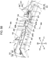
- Figs. 5A , 5B , 8B , and 11A illustrate a state where the intercepting part 28a has just reached the restraining oblong hole 21.
- the intercepting part 28a positioned in the restraining oblong hole 21 is restrained from moving significantly in the horizontal direction (X1-X2 direction).
- Fig. 5A , 5B , 8B , and 11A illustrate a state where the intercepting part 28a has just reached the restraining oblong hole 21.
- the intercepting part 28a positioned in the restraining oblong hole 21 is restrained from moving significantly in the horizontal direction (X1-X2 direction).
- the rear facing part 28b of the restraining projection 28 faces the rear vertical restraining guide 24a at the top of the restraining rib 24, and the front facing part 28c of the restraining projection 28 faces the front vertical restraining guide 25a at the inner surface of the housing 4, whereby the restraining projection 28 is restrained from moving significantly in the vertical direction (Z1-Z2 direction). Therefore, once the cover 3 reaches this position, the cover 3 is hardly detachable from the back face 2b of the device body 2, even if the force of pressing the cover 3 into contact with the back face 2b is reduced.
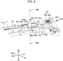
- Figs. 6 and 8C illustrate a state where the cover 3 has been slid further in the latching-force-acting direction (Y1 direction) and the intercepting part 28a of the restraining projection 28 has reached the Y1-side end of the restraining oblong hole 21 provided in the housing 4.
- the intercepting part 28a of the restraining projection 28 is still positioned in the restraining oblong hole 21 and is therefore restrained from moving in the horizontal direction (X1-X2 direction).
- FIG. 10 illustrates, in sectional view, the positions of the cover 3 and the restraining projection 28 at two time points that are taken while the cover 3 and the restraining projection 28 are moving in the latching-force-acting direction (Y1 direction).
- the restraining projection 28 positioned as illustrated in Figs. 6 and 8C is illustrated by the solid line and denoted by (vi).
- a section of the restraining projection 28 positioned as illustrated in Fig. 6 that is taken along line XIB-XIB is illustrated in Fig. 11B .
- the restraining projection 28 When the restraining projection 28 thus guided reaches the "approach restraining guide" constituted by the rear approach restraining guide 24c and the front approach restraining guide 25c, the restraining projection 28 is moved in the Z1 direction while the cover 3 is kept being restrained in the vertical direction (Z1-Z2 direction), whereby the cover 3 is guided to approach the back face 2b of the device body 2.
- the upper latching mechanism 30f behaves as illustrated in Fig.
- the locking projection 32 included in the projecting latch 31 reaches such a height level as to be insertable into the locking hole 35 included in the receiving hole 34, while the latching projection 33 reaches such a height level as to be insertable into the latching hole 36.
- the lower latching mechanism 30r as illustrated in Fig. 4B : the locking projection 32 provided on the device body 2 reaches such a height level as to face the locking hole 35 of the cover 3 to be able to go thereinto, while the latching projection 33 reaches such a height level as to face the latching recess 37 to be able to latch thereinto.
- the second press-contact projection 16 provided on the cover 3 leaves the second press-contact slide part 12a, and most part of the press-contact projection 16 rests on the third press-contact slide part 13a of the third guiding rib 13. Since the second press-contact projection 16, which is substantially integrated with the projecting latch 31, rests on the third press-contact slide part 13a, the projecting latch 31 is stabilized at such a height level as to face the receiving hole 34.
- the latching projection 28 is restrained by the "vertical restraining guide”.
- the latching projection 28 is guided to the "approach restraining guide", where the cover 3 is made to approach the back face 2b of the device body 2.
- the projecting latch 31 is positioned to face the receiving hole 34. This approaching motion of the cover 3 is sensible by the hand. Therefore, whether the cover 3 has successfully reached such a position as to be latchable onto the device body 2 is assuredly recognized, despite the unseeable situation.
- the upper latching mechanism 30f behaves as follows: the locking projection 32 included in the projecting latch 31 goes into the locking hole 35 included in the receiving hole 34, while the latching projection 33 goes into the latching hole 36.
- the locking projection 32 goes into the locking hole 35, the vertical locking rib 32a and the horizontal locking rib 32b come into contact with the inner peripheral edge of the locking hole 35, whereby the cover 3 is restrained from moving in the vertical direction (Z1-Z2 direction) and in the horizontal direction (X1-X2 direction) relative to the device body 2.
- the hook 33a latches onto the Y1-side outer surface of the housing 4 at the Z1-side edge of the latching hole 36.
- the locking projection 32 goes into the locking hole 35, whereby the cover 3 is restrained in the vertical direction (Z1-Z2 direction) and in the horizontal direction (X1-X2 direction) relative to the device body 2.
- the latching projection 33 goes into the latching recess 37, and the hook 33a latches onto the Y2-side outer surface of the housing 4 at the Z2-side edge of the latching recess 37. Since the upper latching mechanism 30f and the lower latching mechanism 30r both behave such that the projecting latches 31 latch into the respective receiving holes 34, the cover 3 is positioned relative to the device body 2 and is fastened to the device body 2.
- the press-contact guide 10A behave as follows.
- the first press-contact projection 15 moves in the Y1 direction to leave the first press-contact slide part 11a.
- the second press-contact projection 16 moves in the Y1 direction to leave the second press-contact slide part 12a, further moves in the Y1 direction to leave the third press-contact slide part 13a, and eventually reaches a position spaced apart from the press-contact-disabling part 13b in the Z2 direction.
- the device body 2 and the cover 3 go out of contact with each other.
- the restraining guide 10B the restraining projection 28 moves into the restraint-disabling opening 23 provided in the housing 4.
- the device body 2 and the cover 3 go out of contact with each other.
- the device body 2 and the cover 3 latch onto each other and are thus fastened to each other at the upper latching mechanism 30f and the lower latching mechanism 30r, the device body 2 and the cover 3 go out of contact with each other in both the press-contact guide 10A and the restraining guide 10B. Therefore, even if the onboard display device 1 is subjected to external vibrations such as vibrations of the vehicle body, noise due to wobbling between the device body 2 and the cover 3 is prevented from occurring in the press-contact guide 10A and in the restraining guide 10B.
- the time point when the device body 2 and the cover 3 go out of contact with each other in the press-contact guide 10A and in the restraining guide 10B as described above is preferably after the time point when the cover 3 positioned as illustrated in Fig. 6 and as denoted by (vi) in Fig. 10 is moved in the latching-force-acting direction (Y1 direction) and the projecting latch 31 starts to go into the receiving hole 34 in at least one of the upper latching mechanism 30f and the lower latching mechanism 30r.
- the cover 3 assuredly keeps being positioned relative to the device body 2 and fastened to the device body 2 by at least one of the upper latching mechanism 30f and the lower latching mechanism 30r even after the cover 3 goes out of contact with the device body 2 in the press-contact guide 10A and in the restraining guide 10B.
Landscapes
- Engineering & Computer Science (AREA)
- Microelectronics & Electronic Packaging (AREA)
- Mechanical Engineering (AREA)
- Chemical & Material Sciences (AREA)
- Combustion & Propulsion (AREA)
- Transportation (AREA)
- Casings For Electric Apparatus (AREA)
Abstract
Description
- The present invention relates to electronic devices having various electronic functions, such as onboard display devices, and particularly relates to an electronic device equipped with a cover that is fastened to a device body by latching onto the device body.
- An electronic-device housing is disclosed by
JP 8-130382 A - To attach the cover to the case, the fitting protrusions provided on the one-end wall of the cover are fitted into the respective holes provided in the one-end wall of the case, and the cover is rotated about the fitted part where the fitting protrusions are fitted into the holes and in such a manner as to be pushed toward the case. In this process, the catches of the cover slide along the outer surfaces of the engaging ribs of the case that have the slide grooves. When the cover is further pushed toward the case, the engaging ribs elastically deform to allow the catches to engage with the slide grooves. Thus, the cover is attached to the case.
- In the electronic-device housing disclosed by
JP 8-130382 A - In the electronic-device housing disclosed by
JP 8-130382 A - An object of the present invention is to provide a cover-equipped electronic device configured such that a cover is easily attachable to a device body and, after the cover is attached to the device body, noise due to wobbling is reduced with a minimized number of points of contact between the device body and the cover.
- The invention relates to a cover-equipped electronic device according to the appended claims. Embodiments are disclosed in the depended claims.
- A cover-equipped electronic device according to an aspect of the present invention includes:
- a device body; and
- a cover to be attached to the device body.
- One of the device body and the cover has a projecting latch, and an other of the device body and the cover has a receiving hole or a receiving recess that is to receive the projecting latch, the projecting latch being configured to latch into the receiving hole or the receiving recess and make the cover attached to the device body when the cover is moved in a predetermined latching-force-acting direction.
- A restraining guide is provided between the device body and the cover and is configured to allow the cover to move in the latching-force-acting direction while restraining the cover in a direction intersecting the latching-force-acting direction.
- Restraint by the restraining guide is disabled when attaching of the cover to the device body is complete with the projecting latch latched into the receiving hole or the receiving recess.
- In the cover-equipped electronic device according to the present invention,
it is preferable that a press-contact guide be provided between the device body and the cover and be configured to cause the device body and the cover to be pressed into contact with each other when the cover is pressed against the device body in the direction intersecting the latching-force-acting direction. - It is also preferable that while the cover that is kept in contact with the device body at the press-contact guide is being moved in the latching-force-acting direction, restraint and guiding by the restraining guide be started.
- In the cover-equipped electronic device according to the present invention,
it is preferable that the restraining guide include - a vertical restraining guide configured to guide the cover in the latching-force-acting direction while restraining the cover in a vertical direction from moving away from the device body; and
- an approach restraining guide configured to bring the cover moved in the latching-force-acting direction along the vertical restraining guide to a position close to the device body where the projecting latch faces the receiving hole or the receiving recess to be able to latch into the receiving hole or the receiving recess.
- In the cover-equipped electronic device according to the present invention, it is preferable that the restraining guide be configured to guide the cover while further restraining the cover in a horizontal direction that intersects both the vertical direction and the latching-force-acting direction.
- The cover-equipped electronic device according to the present invention may be configured as follows.
- The restraining guide has a restraining oblong hole and a restraining projection, the restraining oblong hole being provided in one of the cover and the device body, the restraining projection being provided on an other of the cover and the device body, the restraining oblong hole being elongated in the latching-force-acting direction.
- Furthermore, the restraining projection may be configured to move in the restraining oblong hole such that the cover is guided in the latching-force-acting direction while being restrained in a vertical direction from moving away from the device body and while being further restrained in a horizontal direction that intersects both the vertical direction and the latching-force-acting direction.
- In the cover-equipped electronic device according to the present invention,
it is preferable that a press-contact guide be provided between the device body and the cover and be configured to cause the device body and the cover to be pressed into contact with each other when the cover is pressed against the device body in the direction intersecting the latching-force-acting direction to cause the restraining projection to be inserted into an introduction opening that is continuous with the restraining oblong hole. - It is also preferable that while the cover that is kept in contact with the device body at the press-contact guide is being moved in the latching-force-acting direction, restraint and guiding by the restraining guide be started.
- In the cover-equipped electronic device according to the present invention,
it is preferable that while the cover is being guided in the latching-force-acting direction with the restraining projection moving in the restraining oblong hole, the cover be guided to a position close to the device body where the projecting latch faces the receiving hole or the receiving recess to be able to latch into the receiving hole or the receiving recess. - In the cover-equipped electronic device according to the present invention,
it is preferable that the projecting latch include - a locking projection configured to lock the cover in a vertical direction in such a manner as to prevent the cover from moving away from the device body and configured to further lock the cover in a horizontal direction intersecting both the vertical direction and the latching-force-acting direction, the locking projection locking the cover when being inserted into the receiving hole or the receiving recess; and
- a latching projection configured to make the cover unmovable in the latching-force-acting direction.
- In the cover-equipped electronic device according to the present invention,
for example, the device body is to be installed on a ceiling of a cabin of a vehicle and includes a display screen and an attaching mechanism, the display screen being provided at a front face of the device body, the attaching mechanism being provided at a back face of the device body and allowing the device body to be attached to the vehicle, the attaching mechanism being covered by the cover. - In the cover-equipped electronic device according to aspects of the present invention, to attach the cover to the device body, the cover is simply slid in the latching-force-acting direction while being restrained by the restraining guide. Thus, the projecting latch is assuredly made to latch into the receiving hole or the receiving recess. In the case where the press-contact guide is provided between the device body and the cover, the restraint and guiding by the restraining guide is started by simply pressing the cover into contact with the device body at the press-contact guide and sliding the cover in the latching-force-acting direction. Hence, the attaching of the cover is further facilitated.
- In the cover-equipped electronic device according to aspects of the present invention, when the projecting latch latches into the receiving hole or the receiving recess and the attaching of the cover to the device body is thus complete, the restraint by the restraining guide is disabled. Therefore, after the completion of the attaching, the cover and the device body are kept out of contact with each other at the restraining guide. Accordingly, noise due to wobbling under external vibrations is reduced.
-
Fig. 1 is a lower front perspective view of an onboard display device that is an exemplary electronic device according to the present invention; -
Fig. 2 is a perspective view of the electronic device illustrated inFig. 1 with a device body thereof being oriented such that a display screen extends horizontally and with a cover thereof being detached from the device body; -
Fig. 3 is a perspective view of part of the electronic device oriented such that the display screen extends horizontally and illustrates how to press the cover into contact with the device body in a cover-attaching process; -
Fig. 4A is a rear perspective view of part of the cover and the device body that are pressed into contact with each other at a press-contact guide in the cover-attaching process; -
Fig. 4B is a front perspective view of part of the cover and the device body that are pressed into contact with each other at the press-contact guide in the cover-attaching process; -
Fig. 5A is a rear perspective view of part of the cover and the device body that are pressed into contact with each other at the press-contact guide in the cover-attaching process and illustrates a state established when the cover is slid in a latching-force-acting direction and a restraining projection of a restraining guide is thus positioned in a restraining oblong hole; -
Fig. 5B is a front perspective view of part of the cover and the device body that are pressed into contact with each other at the press-contact guide in the cover-attaching process and illustrates the state established when the cover is slid in the latching-force-acting direction and the restraining projection of the restraining guide is thus positioned in the restraining oblong hole; -
Fig. 6 is a rear perspective view of part of the cover and the device body and illustrates a state established when the cover is further slid in the latching-force-acting direction to be guided by an approach restraining guide of the restraining guide to a position close to the device body where a projecting latch faces a receiving hole to be able to latch into the receiving hole; -
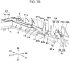
Fig. 7A is a rear perspective view of part of the cover and the device body and illustrates a state established when the cover is further slid in the latching-force-acting direction to cause the projecting latch to latch into the receiving hole and the attaching of the cover to the device body is thus complete; -
Fig. 7B is a front perspective view of part of the cover and the device body and illustrates the state established when the cover is further slid in the latching-force-acting direction to cause the projecting latch to latch into the receiving hole and the attaching of the cover to the device body is thus complete; -
Fig. 8A illustrates a section of part of the cover and the device body in the state illustrated inFigs. 4A and4B and is provided for describing the change in the relative position between the cover and the device body at the restraining guide and the press-contact guide; -
Fig. 8B illustrates a section of part of the cover and the device body in the state illustrated inFigs. 5A and5B and is provided for describing the change in the relative position between the cover and the device body at the restraining guide and the press-contact guide; -
Fig. 8C illustrates a section of part of the cover and the device body in the state illustrated inFig. 6 and is provided for describing the change in the relative position between the cover and the device body at the restraining guide and the press-contact guide; -
Fig. 8D illustrates a section of part of the cover and the device body in the state illustrated inFigs. 7A and7B and is provided for describing the change in the relative position between the cover and the device body at the restraining guide and the press-contact guide; -
Fig. 9 is a perspective view of a section of part of the device body and illustrates configurations of the restraining guide and the press-contact guide; -
Fig. 10 illustrates a section of the cover and the device body and is provided for describing the change in the relative position between a set of the restraining guide and the press-contact guide provided on the device body and a set of the restraining projection and a press-contact projection provided on the cover, with (vi) denoting the positions of the cover and the restraining projection in the state of sliding illustrated inFig. 6 and (vii) denoting the positions of the cover and the restraining projection in the state where latching is complete as illustrated inFigs. 7A and7B ; -
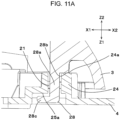
Fig. 11A illustrates how the restraining projection provided on the cover is restrained by the restraining guide provided on the device body in sectional view taken along line XIA-XIA given inFig. 5B ; and -
Fig. 11B illustrates how the restraining projection provided on the cover is restrained by the restraining guide provided on the device body in sectional view taken along line XIB-XIB given inFig. 6 . -
Fig. 1 illustrates anonboard display device 1, which is an exemplary electronic device according to an embodiment of the present invention. Theonboard display device 1 includes adevice body 2 and acover 3. Thecover 3 is attached to the back face, 2b, of thedevice body 2. Thedevice body 2 includes ahousing 4, in which a display unit and an electronic circuit are housed. The display unit has adisplay screen 5, which is exposed at the front face, 2a, of thedevice body 2. The display unit includes display elements such as liquid-crystal display elements or electroluminescent elements. - The
onboard display device 1 illustrated inFig. 1 maybe installed on the ceiling, 6, of the vehicle cabin of an automobile and is viewed obliquely from the lower front. InFig. 2 and inFigs. 3 to 7B , thedevice body 2 is illustrated in an orientation in which thefront face 2a thereof extends horizontally in the drawings, for visibility of relevant structures at theback face 2b of thedevice body 2 and the process of attaching thecover 3 to thedevice body 2. - The orientation of the
onboard display device 1 is defined as follows. The Y1-Y2 direction represents the top-bottom direction with respect to thefront face 2a of thedevice body 2, with the Y1 direction representing the upward direction and the Y2 direction representing the downward direction. The Y1 direction is also referred to as "latching-force-acting direction" in describing the process of attaching thecover 3 to thedevice body 2. The X1-X2 direction represents the left-right direction with respect to thefront face 2a of thedevice body 2, with the X1 direction representing the leftward direction and the X2 direction representing the rightward direction. The X1-X2 direction is also referred to as "horizontal direction" in describing the process of attaching thecover 3 to thedevice body 2. The Z1-Z2 direction defined inFig. 2 and others represents the front-rear direction with respect to thefront face 2a of thedevice body 2, with the Z1 direction representing the frontward direction and the Z2 direction representing the rearward direction (the direction toward theback face 2b). The Z1-Z2 direction is also referred to as "vertical direction" in describing the process of attaching thecover 3 to thedevice body 2. The Z1 direction is also referred to as "approaching direction"; that is, contacting direction or pressing direction, in which thecover 3 is attached to thedevice body 2. The Z2 direction is also referred to as "retreating direction", in which thecover 3 goes away from thedevice body 2. - As illustrated in
Fig. 2 , thedevice body 2 is provided with attachingmechanisms 7 on the left and right sides of theback face 2a thereof. As illustrated inFig. 1 , theceiling 6 of the vehicle cabin has anopening 8, in which a supportingmechanism 9 is fixedly provided. When the attachingmechanisms 7 are coupled to the supportingmechanism 9, thedevice body 2 is fastened to theceiling 6 in such a manner as to hang from theceiling 6. After thedevice body 2 is attached to theceiling 6, thecover 3 is fastened to theback face 2b of thedevice body 2, whereby the points of coupling between the attachingmechanisms 7 and the supportingmechanism 9 are covered by thecover 3. - As illustrated in
Fig. 1 , thedevice body 2 is set up in an orientation in which thedisplay screen 5 thereof faces obliquely frontward and downward. Guidingmechanisms 10 andlatching mechanisms device body 2 and thecover 3 and are therefore unseeable in the process of attaching thecover 3 to theback face 2b of thedevice body 2. Inevitably, the attaching of thecover 3 to thedevice body 2 has to be performed by the feel. In view of such a situation, in theonboard display device 1 according to the embodiment of the present invention, the guidingmechanisms 10 and the latchingmechanisms cover 3 to thedevice body 2. - The
onboard display device 1 illustrated inFig. 2 includes the guidingmechanisms 10 and the latchingmechanisms upper latching mechanisms 30f andlower latching mechanisms 30r, between thedevice body 2 and thecover 3. Specifically, oneguiding mechanism 10 is provided on each of the left and right sides of thedevice body 2, twoupper latching mechanisms 30f are provided on the upper (Y1) side of thedevice body 2, and threelower latching mechanisms 30r are provided on the lower (Y2) side of thedevice body 2. -
Figs. 3 ,9 , and10 illustrate embodiments of configurations of one of the guidingmechanisms 10 and one of theupper latching mechanisms 30f that are located on the right (X2) side.Fig. 3 also illustrates an embodiment of a configuration of one of thelower latching mechanisms 30r. As illustrated inFigs. 3 and9 , each guidingmechanism 10 includes a press-contact guide 10A and a restrainingguide 10B. The press-contact guide 10A and the restrainingguide 10B are formed as part of thedevice body 2 and thecover 3. - As illustrated in
Figs. 3 and9 , the press-contact guide 10A is provided at theback face 2b of thedevice body 2 and includes a first guidingrib 11; asecond guiding rib 12, which is located on the Y1 side relative to the first guidingrib 11; and a third guidingrib 13, which is located on the Y1 side relative to the second guidingrib 12. The guidingribs housing 4 of thedevice body 2 from a material such as synthetic resin or light metal. The guidingribs - The first guiding
rib 11 has at the top thereof a first press-contact slide part 11a. Thesecond guiding rib 12 has at the top thereof a second press-contact slide part 12a. The first press-contact slide part 11a and the second press-contact slide part 12a are at the same height in the Z2 direction from theback face 2b of thedevice body 2. Thethird guiding rib 13 has at the top thereof a third press-contact slide part 13a and a press-contact-disablingpart 13b. The press-contact-disablingpart 13b is located on the Y1 side relative to the third press-contact slide part 13a and is continuous with the third press-contact slide part 13a but at a different height in the Z2 direction from theback face 2b of thedevice body 2. As illustrated inFigs. 9 and10 , the third press-contact slide part 13a is at a lower level than the first press-contact slide part 11a and the second press-contact slide part 12a in such a manner as to be retracted therefrom in the approaching direction (Z1 direction) toward thedevice body 2. The press-contact-disablingpart 13b is at a lower level than the third press-contact slide part 13a in such a manner as to be retracted therefrom in the approaching direction. - As illustrated in
Fig. 4A , thecover 3 has, on aside wall 3a thereof, a first press-contact projection 15 and a second press-contact projection 16, which are constituents of the press-contact guide 10A. The second press-contact projection 16 is located on the Y1 side relative to the first press-contact projection 15. The press-contact projections cover 3 from a material such as synthetic resin or light metal and each extend in the contacting direction (Z1 direction). InFigs. 2 and3 , the second press-contact projection 16 is visible, but the first press-contact projection 15 is hidden behind thecover 3.Fig. 8A illustrates a plane section of the press-contact guide 10A in a state where the first press-contact projection 15 is in contact with the first press-contact slide part 11a of thedevice body 2, and the second press-contact projection 16 is in contact with the second press-contact slide part 12a. - As illustrated in
Figs. 3 ,9 , and8A , at theback face 2b of thedevice body 2, thehousing 4 has a restrainingoblong hole 21. The restrainingoblong hole 21 extends linearly in the latching-force-acting direction (Y1 direction) with a constant width in the horizontal direction (X1-X2 direction). Thehousing 4 further has anintroduction opening 22, which is continuous with the Y2-side end of the restrainingoblong hole 21. Theintroduction opening 22 has a greater width in the horizontal direction (X1-X2 direction) than the restrainingoblong hole 21. As illustrated inFig. 8A , an inner end of the introduction opening 22 that is on the forward side (Y1 side) of the latching-force-acting direction serves as a guidingend 22a. The guidingend 22a is provided on each of the left side (X1 side) and the right side (X2 side) of the restrainingoblong hole 21. The two guiding ends 22a are inclined toward each other while extending in the latching-force-acting direction (Y1 direction). Thehousing 4 further has a restraint-disablingopening 23, which is continuous with the Y1-side end of the restrainingoblong hole 21. The restraint-disablingopening 23 has a greater width in the left-right direction (X1-X2 direction) than the restrainingoblong hole 21. - The
introduction opening 22 and the restraint-disablingopening 23 illustrated inFig. 8A are each a rectangular hole surrounded by thehousing 4. Alternatively, theopenings openings housing 4 and being open on the right side (X2 side) or any other side. - As illustrated in
Figs. 3 and9 , thehousing 4 further has a restrainingrib 24, which is a constituent of the restrainingguide 10B and is formed integrally with thehousing 4 in such a manner as to be raised in the retreating direction (Z2 direction). The top of the restrainingrib 24 that is on the Z2 side extends in the latching-force-acting direction (Y1 direction). The restrainingrib 24 includes at the top thereof a rearvertical restraining guide 24a, a rear inclined restrainingguide 24b, and a rearapproach restraining guide 24c. The rear inclined restrainingguide 24b is continuous with the Y1-side end of the rearvertical restraining guide 24a. The rearapproach restraining guide 24c is continuous with the Y1-side end of the rear inclined restrainingguide 24b. The height of the rearvertical restraining guide 24a from theback face 2b of thehousing 4 is constant. The height of the rearapproach restraining guide 24c from theback face 2b of thehousing 4 is also constant. However, the rearapproach restraining guide 24c is at a lower level than the rearvertical restraining guide 24a in such a manner as to be retracted therefrom in the approaching direction (Z1 direction). The rear inclined restrainingguide 24b is inclined toward theback face 2b of thehousing 4 while extending in the Y1 direction. - As illustrated in
Figs. 9 and10 , part of a surface (inner surface) of thehousing 4 that faces toward the front side (Z1 side) is also a constituent of the restrainingguide 10B. The inner surface of thehousing 4 forms a frontvertical restraining guide 25a, a front inclined restrainingguide 25b, and a frontapproach restraining guide 25c. The front inclined restrainingguide 25b is continuous with the Y1-side end of the frontvertical restraining guide 25a. The frontapproach restraining guide 25c is continuous with the Y1-side end of the front inclined restrainingguide 25b. The frontapproach restraining guide 25c is at a lower level than the frontvertical restraining guide 25a in such a manner as to be retracted therefrom in the approaching direction (Z1 direction). The front inclined restrainingguide 25b is inclined toward the inner side (Z1 side) of thehousing 4 while extending in the Y1 direction. - In the restraining
guide 10B, a combination of the rearvertical restraining guide 24a and the frontvertical restraining guide 25a serves as "vertical restraining guide", and a combination of the rearapproach restraining guide 24c and the frontapproach restraining guide 25c serves as "approach restraining guide". The distance between the rearvertical restraining guide 24a and the frontvertical restraining guide 25a in the Z1-Z2 direction is equal to the distance between the rearapproach restraining guide 24c and the frontapproach restraining guide 25c in the Z1-Z2 direction. - As illustrated in
Figs. 2 ,3 , and11A , thecover 3 has a restrainingprojection 28, which projects in the approaching direction (Z1 direction) from theside wall 3a and is formed integrally with thecover 3. The restrainingprojection 28 is also a constituent of the restrainingguide 10B. The restrainingprojection 28 includes an interceptingpart 28a, arear facing part 28b, and afront facing part 28c. The interceptingpart 28a has a constant width in the horizontal direction (X1-X2 direction) within a certain area in the vertical direction (Z1-Z2 direction). Therear facing part 28b extends from the retreating-side (Z2-side) end of the interceptingpart 28a toward the right side (X2 side). Thefront facing part 28c extends from the approaching-side (Z1-side) end of the interceptingpart 28a toward the left side (X1 side). - In
Figs. 11A and11B , the interceptingpart 28a of the restrainingprojection 28 is positioned in the restrainingoblong hole 21 provided in thehousing 4. The space for the interceptingpart 28a in the restrainingoblong hole 21 in the horizontal direction (X1-X2 direction) is small enough to restrain the restrainingprojection 28 from moving in the horizontal direction. InFig. 11A , therear facing part 28b of the restrainingprojection 28 faces the rearvertical restraining guide 24a at the top of the restrainingrib 24, and thefront facing part 28c faces the frontvertical restraining guide 25a at the inner surface of thehousing 4. In this state, the restrainingprojection 28 and thecover 3 are restrained from moving in the vertical direction (Z1-Z2 direction). InFig. 11B , therear facing part 28b of the restrainingprojection 28 faces the rearapproach restraining guide 24c at the top of the restrainingrib 24, and thefront facing part 28c faces the frontapproach restraining guide 25c at the inner surface of thehousing 4. In this state, the restrainingprojection 28 and thecover 3 are restrained from moving in the vertical direction (Z1-Z2 direction) at a position lowered in the approaching direction (Z1 direction). - As illustrated in
Fig. 2 , thedevice body 2 has theguiding mechanism 10 on the left side (X1 side) as well. The configuration of theguiding mechanism 10 provided on the left side and the configuration of theguiding mechanism 10 provided on the right side and described above are in bilateral symmetry in the horizontal direction (X1-X2 direction). - The configuration of the
guiding mechanism 10 may be inverted from the one described in the present embodiment. Specifically, in the press-contact guide 10A, thecover 3 may have the first guidingrib 11, the second guidingrib 12, and the third guidingrib 13, while thedevice body 2 may have the first press-contact projection 15 and the second press-contact projection 16. Likewise, in the restrainingguide 10B, thecover 3 may have the rearvertical restraining guide 24a, the frontvertical restraining guide 25a, the rearapproach restraining guide 24c, the frontapproach restraining guide 25c, the restrainingoblong hole 21, and other relevant elements, while thedevice body 2 may have the restrainingprojection 28. -
Figs. 3 and4A each illustrate one of the twoupper latching mechanisms 30f. Eachupper latching mechanism 30f includes a projectinglatch 31 and a receivinghole 34. The projectinglatch 31 is formed integrally with thecover 3. The receivinghole 34 is provided in thehousing 4 of thedevice body 2. The projectinglatch 31 includes a lockingprojection 32 and a latchingprojection 33. As illustrated inFigs. 3 ,7A , and7B , the lockingprojection 32 includes avertical locking rib 32a and ahorizontal locking rib 32b. Thevertical locking rib 32a projects in the vertical direction (Z1-Z2 direction) while extending in the latching-force-acting direction (Y1 direction). Thehorizontal locking rib 32b projects in the horizontal direction (X1-X2 direction) while extending in the latching-force-acting direction (Y1 direction). The latchingprojection 33 is elastically deformable in the retreating direction (Z2 direction) and includes at the tip thereof ahook 33a, which projects in the Z1 direction and is formed integrally with the latchingprojection 33. The receivinghole 34 includes a lockinghole 35 and a latchinghole 36. - When the
cover 3 is guided in the latching-force-acting direction (Y1 direction) by the guidingmechanism 10, the lockingprojection 32 goes into the lockinghole 35 and the latchingprojection 33 goes into the latchinghole 36. As illustrated inFigs. 7A and7B , when the lockingprojection 32 goes into the lockinghole 35, thevertical locking rib 32a and thehorizontal locking rib 32b come into contact with the inner peripheral edge of the lockinghole 35, whereby thecover 3 is locked in the vertical direction (Z1-Z2 direction) and in the horizontal direction (X1-X2 direction) relative to thedevice body 2. Meanwhile, when the latchingprojection 33 goes into the latchinghole 36, the latchingprojection 33 elastically deforms in the Z2 direction. When the latchingprojection 33 further advances, thehook 33a thereof latches onto the Y1-side outer surface of thehousing 4 at the Z1-side edge of the latchinghole 36. Thus, thecover 3 latches onto thedevice body 2 and is restrained from moving in the Y2 direction. -
Fig. 4B illustrates one of the threelower latching mechanisms 30r. Eachlower latching mechanism 30r includes a projectinglatch 31 and a receivinghole 34. The projectinglatch 31 is provided on thehousing 4 of thedevice body 2. The receivinghole 34 is provided in thecover 3. The projectinglatch 31 includes a lockingprojection 32 and a latchingprojection 33, both of which project in the Y2 direction. The lockingprojection 32 includes avertical locking rib 32a, which projects in the vertical direction (Z1-Z2 direction); and ahorizontal locking rib 32b, which projects in the horizontal direction (X1-X2 direction). The latchingprojection 33 is elastically deformable in the approaching direction (Z1 direction) and includes at the tip thereof ahook 33a, which projects in the Z2 direction and is formed integrally with the latchingprojection 33. The receivinghole 34 includes a lockinghole 35 and a latchingrecess 37. - In the
lower latching mechanism 30r as well, when thecover 3 is guided in the latching-force-acting direction (Y1 direction) by the guidingmechanism 10, the lockingprojection 32 goes into the lockinghole 35 and the latchingprojection 33 goes into the latchingrecess 37. When the lockingprojection 32 goes into the lockinghole 35, thecover 3 is locked in the vertical direction (Z1-Z2 direction) and in the horizontal direction (X1-X2 direction) relative to thedevice body 2. Meanwhile, when the latchingprojection 33 goes into the latchingrecess 37, the latchingprojection 33 elastically deforms in the Z1 direction. Then, thehook 33a latches onto the Y2-side outer surface of thehousing 4 at the Z2-side edge of the latchingrecess 37. Thus, thecover 3 is fastened to thedevice body 2 and is restrained from moving in the Y1 direction. - When the
cover 3 is moved in the latching-force-acting direction (Y1 direction), theupper latching mechanisms 30f and thelower latching mechanisms 30r simultaneously behave such that the projecting latches 31 latch into the respective receiving holes 34. Thus, thecover 3 is attached to and fastened to thedevice body 2 in such a manner as not to move easily. - In the
upper latching mechanisms 30f and thelower latching mechanisms 30r, some or all of the locking holes 35 and the latching holes 36 included in the receiving holes 34 may be replaced with receiving recesses. Herein, a receiving recess refers to a hole with part of the peripheral edge thereof being open, such as the latchingrecess 37. Alternatively, the receiving recess may be shaped like a folder having an opening with a predetermined length (depth) in the Y1-Y2 direction. Even if the receiving holes 34 are replaced with such receiving recesses, specifically locking recesses and latching recesses, thecover 3 is positioned relative to thedevice body 2 when the lockingprojections 32 are inserted into the respective locking recesses, and thecover 3 latches onto thedevice body 2 when the latchingprojections 33 are inserted into the respective latching recesses. - How to attach the
cover 3 to thedevice body 2 will now be described. - Referring to
Fig. 1 , to attach theonboard display device 1 to a vehicle cabin, thecover 3 is detached from thedevice body 2 as illustrated by the broken lines. In this state, the attaching mechanisms 7 (seeFig. 2 ) at theback face 2b of thedevice body 2 are coupled to the supportingmechanism 9 located in theopening 8 of theceiling 6. Subsequently, thecover 3 is attached to theback face 2b of thedevice body 2 attached to theceiling 6, whereby the points of coupling between the attachingmechanisms 7 and the supportingmechanism 9 are covered by thecover 3. In this process, since the points of engagement between theback face 2b of thedevice body 2 and thecover 3 are difficult to see, the attaching of thecover 3 is performed by the feel. Nevertheless, in theonboard display device 1 according to the present embodiment, the guidingmechanisms 10 and the latchingmechanisms cover 3 to thedevice body 2. Specifically, thecover 3 is pressed against theback face 2b of thedevice body 2 and is then slid in the latching-force-acting direction (Y1 direction). - The
cover 3 is attached to thedevice body 2 in the orientation illustrated inFig. 1 . However, for simplicity, the following description of the process of attaching thecover 3 that is given with reference toFig. 2 and the subsequent drawings is based on the orientation in which thefront face 2a of thedevice body 2 extends horizontally. - In the process of attaching the
cover 3, thecover 3 is fitted to theback face 2b of thedevice body 2 in the Z1 direction. Specifically, when the restrainingprojection 28 provided on each of the left and right sides of thecover 3 is inserted into the introduction opening 22 provided in thehousing 4, as illustrated inFigs. 4A ,4B , and8A , the first press-contact projection 15 provided on thecover 3 is pressed into contact with the first press-contact slide part 11a of the first guidingrib 11 provided on thehousing 4, while the second press-contact projection 16 provided on thecover 3 is pressed into contact with the second press-contact slide part 12a of the second guidingrib 12. - If the restraining
projection 28 fails to be inserted into the introduction opening 22, the restrainingprojection 28 interferes with theback face 2b of thehousing 4. Such a situation hinders the first press-contact projection 15 and the second press-contact projection 16 from coming into contact with the first press-contact slide part 11a and the second press-contact slide part 12a. That is, when the restrainingprojection 28 is successfully inserted into the introduction opening 22, thecover 3 is guided such that the first press-contact projection 15 comes into contact with the first press-contact slide part 11a and the second press-contact projection 16 comes into contact with the second press-contact slide part 12a. Therefore, even if the points of contact between thecover 3 and thedevice body 2 are directly unseeable, pressing thecover 3 into contact with theback face 2b of thedevice body 2 provides a tactile sensation of whether the press-contact projections contact slide parts cover 3 is pressed into contact with theback face 2b of thedevice body 2 in a proper position is recognizable. - Subsequently, as illustrated in
Figs. 4A ,4B , and8A , while the first press-contact projection 15 and the second press-contact projection 16 are kept in contact with the first press-contact slide part 11a and the second press-contact slide part 12a, thecover 3 is slid in the latching-force-acting direction (Y1 direction). This sliding causes the interceptingpart 28a of the restrainingprojection 28 provided on thecover 3 to go into the restrainingoblong hole 21 provided in thehousing 4. -
Figs. 5A ,5B ,8B , and11A illustrate a state where the interceptingpart 28a has just reached the restrainingoblong hole 21. In this state, the interceptingpart 28a positioned in the restrainingoblong hole 21 is restrained from moving significantly in the horizontal direction (X1-X2 direction). Furthermore, as illustrated inFig. 11A in sectional view, therear facing part 28b of the restrainingprojection 28 faces the rearvertical restraining guide 24a at the top of the restrainingrib 24, and thefront facing part 28c of the restrainingprojection 28 faces the frontvertical restraining guide 25a at the inner surface of thehousing 4, whereby the restrainingprojection 28 is restrained from moving significantly in the vertical direction (Z1-Z2 direction). Therefore, once thecover 3 reaches this position, thecover 3 is hardly detachable from theback face 2b of thedevice body 2, even if the force of pressing thecover 3 into contact with theback face 2b is reduced. -
Figs. 6 and8C illustrate a state where thecover 3 has been slid further in the latching-force-acting direction (Y1 direction) and the interceptingpart 28a of the restrainingprojection 28 has reached the Y1-side end of the restrainingoblong hole 21 provided in thehousing 4. In this state, the interceptingpart 28a of the restrainingprojection 28 is still positioned in the restrainingoblong hole 21 and is therefore restrained from moving in the horizontal direction (X1-X2 direction).Fig. 10 illustrates, in sectional view, the positions of thecover 3 and the restrainingprojection 28 at two time points that are taken while thecover 3 and the restrainingprojection 28 are moving in the latching-force-acting direction (Y1 direction). InFig. 10 , the restrainingprojection 28 positioned as illustrated inFigs. 6 and8C is illustrated by the solid line and denoted by (vi). A section of the restrainingprojection 28 positioned as illustrated inFig. 6 that is taken along line XIB-XIB is illustrated inFig. 11B . - As illustrated in
Figs. 6 ,10 , and11B , when thecover 3 that is being restrained by the restrainingguide 10B is slid in the latching-force-acting direction (Y1 direction), therear facing part 28b of the restrainingprojection 28 moves from the rearvertical restraining guide 24a of the restrainingrib 24 along the rear inclined restrainingguide 24b and comes to face the rearapproach restraining guide 24c. Meanwhile, thefront facing part 28c of the restrainingprojection 28 moves from the frontvertical restraining guide 25a at the inner surface of thehousing 4 along the front inclined restrainingguide 25b and comes to face the frontapproach restraining guide 25c. - When the restraining
projection 28 thus guided reaches the "approach restraining guide" constituted by the rearapproach restraining guide 24c and the frontapproach restraining guide 25c, the restrainingprojection 28 is moved in the Z1 direction while thecover 3 is kept being restrained in the vertical direction (Z1-Z2 direction), whereby thecover 3 is guided to approach theback face 2b of thedevice body 2. When thecover 3 approaches theback face 2b of thedevice body 2, theupper latching mechanism 30f behaves as illustrated inFig. 6 : the lockingprojection 32 included in the projectinglatch 31 reaches such a height level as to be insertable into the lockinghole 35 included in the receivinghole 34, while the latchingprojection 33 reaches such a height level as to be insertable into the latchinghole 36. The same applies to thelower latching mechanism 30r, as illustrated inFig. 4B : the lockingprojection 32 provided on thedevice body 2 reaches such a height level as to face the lockinghole 35 of thecover 3 to be able to go thereinto, while the latchingprojection 33 reaches such a height level as to face the latchingrecess 37 to be able to latch thereinto. - In this state, as illustrated in
Fig. 6 and as denoted by (vi) inFig. 10 , the second press-contact projection 16 provided on thecover 3 leaves the second press-contact slide part 12a, and most part of the press-contact projection 16 rests on the third press-contact slide part 13a of the third guidingrib 13. Since the second press-contact projection 16, which is substantially integrated with the projectinglatch 31, rests on the third press-contact slide part 13a, the projectinglatch 31 is stabilized at such a height level as to face the receivinghole 34. - In the restraining
guide 10B, when thecover 3 is slid in the latching-force-acting direction, the latchingprojection 28 is restrained by the "vertical restraining guide". When thecover 3 is further slid in the latching-force-acting direction, the latchingprojection 28 is guided to the "approach restraining guide", where thecover 3 is made to approach theback face 2b of thedevice body 2. Thus, the projectinglatch 31 is positioned to face the receivinghole 34. This approaching motion of thecover 3 is sensible by the hand. Therefore, whether thecover 3 has successfully reached such a position as to be latchable onto thedevice body 2 is assuredly recognized, despite the unseeable situation. - As illustrated in
Fig. 6 and as denoted by (vi) inFig. 10 , when thecover 3 guided to the position close to theback face 2b of thedevice body 2 is further moved by the hand in the latching-force-acting direction (Y1 direction), thecover 3 and thedevice body 2 latch onto each other at the latchingmechanisms Figs. 7A ,7B , and8D . In this state, referring toFig. 10 , the restrainingprojection 28 and thecover 3 are positioned as illustrated by the broken lines and denoted by (vii). - When the
cover 3 is positioned as illustrated inFigs. 7A ,7B , and8D and as denoted by (vii) inFig. 10 , theupper latching mechanism 30f behaves as follows: the lockingprojection 32 included in the projectinglatch 31 goes into the lockinghole 35 included in the receivinghole 34, while the latchingprojection 33 goes into the latchinghole 36. When the lockingprojection 32 goes into the lockinghole 35, thevertical locking rib 32a and thehorizontal locking rib 32b come into contact with the inner peripheral edge of the lockinghole 35, whereby thecover 3 is restrained from moving in the vertical direction (Z1-Z2 direction) and in the horizontal direction (X1-X2 direction) relative to thedevice body 2. Meanwhile, when the latchingprojection 33 goes into the latchinghole 36, thehook 33a latches onto the Y1-side outer surface of thehousing 4 at the Z1-side edge of the latchinghole 36. Likewise, in thelower latching mechanism 30r, the lockingprojection 32 goes into the lockinghole 35, whereby thecover 3 is restrained in the vertical direction (Z1-Z2 direction) and in the horizontal direction (X1-X2 direction) relative to thedevice body 2. Simultaneously, the latchingprojection 33 goes into the latchingrecess 37, and thehook 33a latches onto the Y2-side outer surface of thehousing 4 at the Z2-side edge of the latchingrecess 37. Since theupper latching mechanism 30f and thelower latching mechanism 30r both behave such that the projecting latches 31 latch into the respective receiving holes 34, thecover 3 is positioned relative to thedevice body 2 and is fastened to thedevice body 2. - When the
device body 2 and thecover 3 latch onto each other and are thus fastened to each other at theupper latching mechanism 30f and thelower latching mechanism 30r as illustrated inFigs. 7A ,7B , and8D and as denoted by (vii) inFig. 10 , the press-contact guide 10A behave as follows. The first press-contact projection 15 moves in the Y1 direction to leave the first press-contact slide part 11a. Meanwhile, the second press-contact projection 16 moves in the Y1 direction to leave the second press-contact slide part 12a, further moves in the Y1 direction to leave the third press-contact slide part 13a, and eventually reaches a position spaced apart from the press-contact-disablingpart 13b in the Z2 direction. Hence, in the press-contact guide 10A, thedevice body 2 and thecover 3 go out of contact with each other. Meanwhile, in the restrainingguide 10B, the restrainingprojection 28 moves into the restraint-disablingopening 23 provided in thehousing 4. Hence, in the restrainingguide 10B as well, thedevice body 2 and thecover 3 go out of contact with each other. - When the
device body 2 and thecover 3 latch onto each other and are thus fastened to each other at theupper latching mechanism 30f and thelower latching mechanism 30r, thedevice body 2 and thecover 3 go out of contact with each other in both the press-contact guide 10A and the restrainingguide 10B. Therefore, even if theonboard display device 1 is subjected to external vibrations such as vibrations of the vehicle body, noise due to wobbling between thedevice body 2 and thecover 3 is prevented from occurring in the press-contact guide 10A and in the restrainingguide 10B. - The time point when the
device body 2 and thecover 3 go out of contact with each other in the press-contact guide 10A and in the restrainingguide 10B as described above is preferably after the time point when thecover 3 positioned as illustrated inFig. 6 and as denoted by (vi) inFig. 10 is moved in the latching-force-acting direction (Y1 direction) and the projectinglatch 31 starts to go into the receivinghole 34 in at least one of theupper latching mechanism 30f and thelower latching mechanism 30r. In such a configuration, thecover 3 assuredly keeps being positioned relative to thedevice body 2 and fastened to thedevice body 2 by at least one of theupper latching mechanism 30f and thelower latching mechanism 30r even after thecover 3 goes out of contact with thedevice body 2 in the press-contact guide 10A and in the restrainingguide 10B.
Claims (9)
- A cover-equipped electronic device (1) comprising:a device body (2); anda cover (3) to be attached to the device body,wherein one of the device body and the cover has a projecting latch (31), and an other of the device body and the cover has a receiving hole or a receiving recess (34) that is configured to receive the projecting latch, the projecting latch being configured to latch into the receiving hole or the receiving recess and make the cover attached to the device body when the cover is moved in a predetermined latching-force-acting direction (Y1);wherein a restraining guide (10B) is provided between the device body and the cover and is configured to allow the cover to move in the latching-force-acting direction while restraining the cover in a direction intersecting the latching-force-acting direction; andwherein restraint by the restraining guide is disabled when attaching of the cover to the device body is complete with the projecting latch latched into the receiving hole or the receiving recess.
- The cover-equipped electronic device according to Claim 1,wherein a press-contact guide (10A) is provided between the device body and the cover and is configured to cause the device body and the cover to be pressed into contact with each other when the cover is pressed against the device body in the direction intersecting the latching-force-acting direction; andwherein while the cover that is kept in contact with the device body at the press-contact guide is being moved in the latching-force-acting direction, restraint and guiding by the restraining guide is started.
- The cover-equipped electronic device according to Claim 1 or 2,
wherein the restraining guide includesa vertical restraining guide (24a, 25a) configured to guide the cover in the latching-force-acting direction while restraining the cover in a vertical direction (Z1-Z2) from moving away from the device body; andan approach restraining guide (24c, 25c) configured to bring the cover moved in the latching-force-acting direction along the vertical restraining guide to a position close to the device body where the projecting latch faces the receiving hole or the receiving recess to be able to latch into the receiving hole or the receiving recess. - The cover-equipped electronic device according to Claim 3,
wherein the restraining guide is configured to guide the cover while further restraining the cover in a horizontal direction (X1-X2) that intersects both the vertical direction and the latching-force-acting direction. - The cover-equipped electronic device according to one of Claims 1 - 4,wherein the restraining guide has a restraining oblong hole (21) and a restraining projection (28), the restraining oblong hole being provided in one of the cover and the device body, the restraining projection being provided on an other of the cover and the device body, the restraining oblong hole being elongated in the latching-force-acting direction; andwherein the restraining projection is configured to move in the restraining oblong hole such that the cover is guided in the latching-force-acting direction while being restrained in a vertical direction (Z1-Z2) from moving away from the device body and while being further restrained in a horizontal direction (X1-X2) that intersects both the vertical direction and the latching-force-acting direction.
- The cover-equipped electronic device according to Claim 5,wherein a press-contact guide (10A) is provided between the device body and the cover and is configured to cause the device body and the cover to be pressed into contact with each other when the cover is pressed against the device body in the direction intersecting the latching-force-acting direction to cause the restraining projection to be inserted into an introduction opening (22) that is continuous with the restraining oblong hole; andwherein while the cover that is kept in contact with the device body at the press-contact guide is being moved in the latching-force-acting direction, restraint and guiding by the restraining guide is started.
- The cover-equipped electronic device according to Claim 5 or 6,
wherein while the cover is being guided in the latching-force-acting direction with the restraining projection moving in the restraining oblong hole, the cover is guided to a position close to the device body where the projecting latch faces the receiving hole or the receiving recess to be able to latch into the receiving hole or the receiving recess. - The cover-equipped electronic device according to any of Claims 1, 2, 5, and 6,
wherein the projecting latch includesa locking projection (32) configured to lock the cover in a vertical direction (Z1-Z2) in such a manner as to prevent the cover from moving away from the device body and configured to further lock the cover in a horizontal direction (X1-X2) intersecting both the vertical direction and the latching-force-acting direction, the locking projection locking the cover when being inserted into the receiving hole or the receiving recess; anda latching projection (33) configured to make the cover unmovable in the latching-force-acting direction. - The cover-equipped electronic device according to one of Claims 1 - 8,
wherein the device body is to be installed on a ceiling (6) of a cabin of a vehicle and includes a display screen (5) and an attaching mechanism (7), the display screen being provided at a front face (2a) of the device body, the attaching mechanism being provided at a back face (2b) of the device body and allowing the device body to be attached to the vehicle, the attaching mechanism being covered by the cover.
Applications Claiming Priority (1)
| Application Number | Priority Date | Filing Date | Title |
|---|---|---|---|
| JP2022135028A JP2024031463A (en) | 2022-08-26 | 2022-08-26 | electronic device with cover |
Publications (2)
| Publication Number | Publication Date |
|---|---|
| EP4328065A1 true EP4328065A1 (en) | 2024-02-28 |
| EP4328065B1 EP4328065B1 (en) | 2025-06-04 |
Family
ID=87557864
Family Applications (1)
| Application Number | Title | Priority Date | Filing Date |
|---|---|---|---|
| EP23189722.4A Active EP4328065B1 (en) | 2022-08-26 | 2023-08-04 | Cover-equipped electronic device |
Country Status (4)
| Country | Link |
|---|---|
| US (1) | US12538445B2 (en) |
| EP (1) | EP4328065B1 (en) |
| JP (1) | JP2024031463A (en) |
| CN (1) | CN117641792A (en) |
Citations (4)
| Publication number | Priority date | Publication date | Assignee | Title |
|---|---|---|---|---|
| DE3929768A1 (en) * | 1989-09-06 | 1991-03-14 | Loewe Opta Gmbh | FASTENING DEVICE FOR THE BACK PANEL OF AN ELECTRONIC DEVICE |
| JPH08130382A (en) | 1994-10-31 | 1996-05-21 | Nec Corp | Electronic equipment case |
| WO2007046789A1 (en) * | 2005-10-17 | 2007-04-26 | Duel Systems | Electronic packages for peripheral devices |
| US20210243909A1 (en) * | 2018-04-25 | 2021-08-05 | Clarion Co., Ltd. | Device casing |
Family Cites Families (2)
| Publication number | Priority date | Publication date | Assignee | Title |
|---|---|---|---|---|
| JP3759723B2 (en) * | 2002-05-16 | 2006-03-29 | 三菱電機株式会社 | Temporary fixing structure for electronic equipment |
| US9535457B1 (en) * | 2014-03-24 | 2017-01-03 | Xplore Technologies Corp. | Docking station with improved latching mechanism |
-
2022
- 2022-08-26 JP JP2022135028A patent/JP2024031463A/en active Pending
-
2023
- 2023-08-04 EP EP23189722.4A patent/EP4328065B1/en active Active
- 2023-08-07 US US18/366,482 patent/US12538445B2/en active Active
- 2023-08-24 CN CN202311070160.9A patent/CN117641792A/en active Pending
Patent Citations (4)
| Publication number | Priority date | Publication date | Assignee | Title |
|---|---|---|---|---|
| DE3929768A1 (en) * | 1989-09-06 | 1991-03-14 | Loewe Opta Gmbh | FASTENING DEVICE FOR THE BACK PANEL OF AN ELECTRONIC DEVICE |
| JPH08130382A (en) | 1994-10-31 | 1996-05-21 | Nec Corp | Electronic equipment case |
| WO2007046789A1 (en) * | 2005-10-17 | 2007-04-26 | Duel Systems | Electronic packages for peripheral devices |
| US20210243909A1 (en) * | 2018-04-25 | 2021-08-05 | Clarion Co., Ltd. | Device casing |
Also Published As
| Publication number | Publication date |
|---|---|
| JP2024031463A (en) | 2024-03-07 |
| CN117641792A (en) | 2024-03-01 |
| US20240074077A1 (en) | 2024-02-29 |
| EP4328065B1 (en) | 2025-06-04 |
| US12538445B2 (en) | 2026-01-27 |
Similar Documents
| Publication | Publication Date | Title |
|---|---|---|
| US10676040B2 (en) | Cover for onboard electronic device | |
| EP3421296A1 (en) | On-vehicle device and display attachment device | |
| CN112277821A (en) | Bracket for vehicle-mounted device and holding device for vehicle-mounted device | |
| EP3421297A1 (en) | On-vehicle device and display attachment device | |
| JP6499060B2 (en) | Vehicle out-handle device | |
| EP4328065B1 (en) | Cover-equipped electronic device | |
| US20140104866A1 (en) | Vehicle interior illumination lamp mounting structure | |
| JP2000207130A (en) | Operation device | |
| JPH0134366Y2 (en) | ||
| US20020001985A1 (en) | Connector | |
| JP2009231960A (en) | Information communication device | |
| WO2006004153A1 (en) | Electronic device with built-in antenna | |
| JP4675609B2 (en) | Shelf plate mounting device for shelf device | |
| US6778402B2 (en) | Electronic control unit snap-fitted to supporting bracket | |
| JP4872731B2 (en) | Mounting structure of switch device | |
| KR20020020493A (en) | Case for computer | |
| JP7308175B2 (en) | Bracket for in-vehicle equipment and holding device for in-vehicle equipment | |
| JPH05246285A (en) | Antistatic mechanism for in-vehicle equipment | |
| JP2009184581A (en) | Panel attaching/detaching mechanism | |
| JP2671696B2 (en) | Drawer locking device | |
| JP6061717B2 (en) | Automotive electronic devices | |
| JP2020029116A (en) | Panel structure | |
| JPH0616831Y2 (en) | Assembly structure of vehicle ashtray | |
| JP2020022047A (en) | Antenna bracket | |
| JP2026081672A (en) | Switch device mounting structure |
Legal Events
| Date | Code | Title | Description |
|---|---|---|---|
| PUAI | Public reference made under article 153(3) epc to a published international application that has entered the european phase |
Free format text: ORIGINAL CODE: 0009012 |
|
| STAA | Information on the status of an ep patent application or granted ep patent |
Free format text: STATUS: THE APPLICATION HAS BEEN PUBLISHED |
|
| AK | Designated contracting states |
Kind code of ref document: A1 Designated state(s): AL AT BE BG CH CY CZ DE DK EE ES FI FR GB GR HR HU IE IS IT LI LT LU LV MC ME MK MT NL NO PL PT RO RS SE SI SK SM TR |
|
| STAA | Information on the status of an ep patent application or granted ep patent |
Free format text: STATUS: REQUEST FOR EXAMINATION WAS MADE |
|
| 17P | Request for examination filed |
Effective date: 20240823 |
|
| RBV | Designated contracting states (corrected) |
Designated state(s): AL AT BE BG CH CY CZ DE DK EE ES FI FR GB GR HR HU IE IS IT LI LT LU LV MC ME MK MT NL NO PL PT RO RS SE SI SK SM TR |
|
| GRAP | Despatch of communication of intention to grant a patent |
Free format text: ORIGINAL CODE: EPIDOSNIGR1 |
|
| STAA | Information on the status of an ep patent application or granted ep patent |
Free format text: STATUS: GRANT OF PATENT IS INTENDED |
|
| RIC1 | Information provided on ipc code assigned before grant |
Ipc: G02F 1/1333 20060101ALI20241212BHEP Ipc: B60R 11/02 20060101ALI20241212BHEP Ipc: B60R 11/00 20060101ALI20241212BHEP Ipc: B60K 35/50 20240101ALI20241212BHEP Ipc: B60K 35/22 20240101AFI20241212BHEP |
|
| INTG | Intention to grant announced |
Effective date: 20250110 |
|
| GRAS | Grant fee paid |
Free format text: ORIGINAL CODE: EPIDOSNIGR3 |
|
| GRAA | (expected) grant |
Free format text: ORIGINAL CODE: 0009210 |
|
| STAA | Information on the status of an ep patent application or granted ep patent |
Free format text: STATUS: THE PATENT HAS BEEN GRANTED |
|
| AK | Designated contracting states |
Kind code of ref document: B1 Designated state(s): AL AT BE BG CH CY CZ DE DK EE ES FI FR GB GR HR HU IE IS IT LI LT LU LV MC ME MK MT NL NO PL PT RO RS SE SI SK SM TR |
|
| P01 | Opt-out of the competence of the unified patent court (upc) registered |
Free format text: CASE NUMBER: APP_20461/2025 Effective date: 20250429 |
|
| REG | Reference to a national code |
Ref country code: GB Ref legal event code: FG4D |
|
| REG | Reference to a national code |
Ref country code: CH Ref legal event code: EP |
|
| REG | Reference to a national code |
Ref country code: DE Ref legal event code: R096 Ref document number: 602023003808 Country of ref document: DE |
|
| REG | Reference to a national code |
Ref country code: IE Ref legal event code: FG4D |
|
| REG | Reference to a national code |
Ref country code: NL Ref legal event code: MP Effective date: 20250604 |
|
| PG25 | Lapsed in a contracting state [announced via postgrant information from national office to epo] |
Ref country code: ES Free format text: LAPSE BECAUSE OF FAILURE TO SUBMIT A TRANSLATION OF THE DESCRIPTION OR TO PAY THE FEE WITHIN THE PRESCRIBED TIME-LIMIT Effective date: 20250604 Ref country code: FI Free format text: LAPSE BECAUSE OF FAILURE TO SUBMIT A TRANSLATION OF THE DESCRIPTION OR TO PAY THE FEE WITHIN THE PRESCRIBED TIME-LIMIT Effective date: 20250604 |
|
| PGFP | Annual fee paid to national office [announced via postgrant information from national office to epo] |
Ref country code: DE Payment date: 20250820 Year of fee payment: 3 |
|
| REG | Reference to a national code |
Ref country code: LT Ref legal event code: MG9D |
|
| PG25 | Lapsed in a contracting state [announced via postgrant information from national office to epo] |
Ref country code: GR Free format text: LAPSE BECAUSE OF FAILURE TO SUBMIT A TRANSLATION OF THE DESCRIPTION OR TO PAY THE FEE WITHIN THE PRESCRIBED TIME-LIMIT Effective date: 20250905 Ref country code: NO Free format text: LAPSE BECAUSE OF FAILURE TO SUBMIT A TRANSLATION OF THE DESCRIPTION OR TO PAY THE FEE WITHIN THE PRESCRIBED TIME-LIMIT Effective date: 20250904 |
|
| PG25 | Lapsed in a contracting state [announced via postgrant information from national office to epo] |
Ref country code: PL Free format text: LAPSE BECAUSE OF FAILURE TO SUBMIT A TRANSLATION OF THE DESCRIPTION OR TO PAY THE FEE WITHIN THE PRESCRIBED TIME-LIMIT Effective date: 20250604 |
|
| PG25 | Lapsed in a contracting state [announced via postgrant information from national office to epo] |
Ref country code: BG Free format text: LAPSE BECAUSE OF FAILURE TO SUBMIT A TRANSLATION OF THE DESCRIPTION OR TO PAY THE FEE WITHIN THE PRESCRIBED TIME-LIMIT Effective date: 20250604 |
|
| PG25 | Lapsed in a contracting state [announced via postgrant information from national office to epo] |
Ref country code: HR Free format text: LAPSE BECAUSE OF FAILURE TO SUBMIT A TRANSLATION OF THE DESCRIPTION OR TO PAY THE FEE WITHIN THE PRESCRIBED TIME-LIMIT Effective date: 20250604 |
|
| PGFP | Annual fee paid to national office [announced via postgrant information from national office to epo] |
Ref country code: FR Payment date: 20250828 Year of fee payment: 3 Ref country code: AT Payment date: 20251020 Year of fee payment: 3 |
|
| PG25 | Lapsed in a contracting state [announced via postgrant information from national office to epo] |
Ref country code: RS Free format text: LAPSE BECAUSE OF FAILURE TO SUBMIT A TRANSLATION OF THE DESCRIPTION OR TO PAY THE FEE WITHIN THE PRESCRIBED TIME-LIMIT Effective date: 20250904 |
|
| PG25 | Lapsed in a contracting state [announced via postgrant information from national office to epo] |
Ref country code: LV Free format text: LAPSE BECAUSE OF FAILURE TO SUBMIT A TRANSLATION OF THE DESCRIPTION OR TO PAY THE FEE WITHIN THE PRESCRIBED TIME-LIMIT Effective date: 20250604 |
|
| PG25 | Lapsed in a contracting state [announced via postgrant information from national office to epo] |
Ref country code: NL Free format text: LAPSE BECAUSE OF FAILURE TO SUBMIT A TRANSLATION OF THE DESCRIPTION OR TO PAY THE FEE WITHIN THE PRESCRIBED TIME-LIMIT Effective date: 20250604 |
|
| PG25 | Lapsed in a contracting state [announced via postgrant information from national office to epo] |
Ref country code: PT Free format text: LAPSE BECAUSE OF FAILURE TO SUBMIT A TRANSLATION OF THE DESCRIPTION OR TO PAY THE FEE WITHIN THE PRESCRIBED TIME-LIMIT Effective date: 20251006 |
|
| REG | Reference to a national code |
Ref country code: AT Ref legal event code: MK05 Ref document number: 1800038 Country of ref document: AT Kind code of ref document: T Effective date: 20250604 |
|
| PG25 | Lapsed in a contracting state [announced via postgrant information from national office to epo] |
Ref country code: IS Free format text: LAPSE BECAUSE OF FAILURE TO SUBMIT A TRANSLATION OF THE DESCRIPTION OR TO PAY THE FEE WITHIN THE PRESCRIBED TIME-LIMIT Effective date: 20251004 |
|
| PG25 | Lapsed in a contracting state [announced via postgrant information from national office to epo] |
Ref country code: SM Free format text: LAPSE BECAUSE OF FAILURE TO SUBMIT A TRANSLATION OF THE DESCRIPTION OR TO PAY THE FEE WITHIN THE PRESCRIBED TIME-LIMIT Effective date: 20250604 Ref country code: AT Free format text: LAPSE BECAUSE OF FAILURE TO SUBMIT A TRANSLATION OF THE DESCRIPTION OR TO PAY THE FEE WITHIN THE PRESCRIBED TIME-LIMIT Effective date: 20250604 |
|
| PG25 | Lapsed in a contracting state [announced via postgrant information from national office to epo] |
Ref country code: CZ Free format text: LAPSE BECAUSE OF FAILURE TO SUBMIT A TRANSLATION OF THE DESCRIPTION OR TO PAY THE FEE WITHIN THE PRESCRIBED TIME-LIMIT Effective date: 20250604 |
|
| PG25 | Lapsed in a contracting state [announced via postgrant information from national office to epo] |
Ref country code: EE Free format text: LAPSE BECAUSE OF FAILURE TO SUBMIT A TRANSLATION OF THE DESCRIPTION OR TO PAY THE FEE WITHIN THE PRESCRIBED TIME-LIMIT Effective date: 20250604 |
|
| PG25 | Lapsed in a contracting state [announced via postgrant information from national office to epo] |
Ref country code: SK Free format text: LAPSE BECAUSE OF FAILURE TO SUBMIT A TRANSLATION OF THE DESCRIPTION OR TO PAY THE FEE WITHIN THE PRESCRIBED TIME-LIMIT Effective date: 20250604 |
|
| PG25 | Lapsed in a contracting state [announced via postgrant information from national office to epo] |
Ref country code: IT Free format text: LAPSE BECAUSE OF FAILURE TO SUBMIT A TRANSLATION OF THE DESCRIPTION OR TO PAY THE FEE WITHIN THE PRESCRIBED TIME-LIMIT Effective date: 20250604 |
|
| REG | Reference to a national code |
Ref country code: DE Ref legal event code: R097 Ref document number: 602023003808 Country of ref document: DE |
|
| PG25 | Lapsed in a contracting state [announced via postgrant information from national office to epo] |
Ref country code: RO Free format text: LAPSE BECAUSE OF FAILURE TO SUBMIT A TRANSLATION OF THE DESCRIPTION OR TO PAY THE FEE WITHIN THE PRESCRIBED TIME-LIMIT Effective date: 20250604 |
|
| PG25 | Lapsed in a contracting state [announced via postgrant information from national office to epo] |
Ref country code: MC Free format text: LAPSE BECAUSE OF FAILURE TO SUBMIT A TRANSLATION OF THE DESCRIPTION OR TO PAY THE FEE WITHIN THE PRESCRIBED TIME-LIMIT Effective date: 20250604 |
|
| PLBE | No opposition filed within time limit |
Free format text: ORIGINAL CODE: 0009261 |
|
| STAA | Information on the status of an ep patent application or granted ep patent |
Free format text: STATUS: NO OPPOSITION FILED WITHIN TIME LIMIT |
|
| PG25 | Lapsed in a contracting state [announced via postgrant information from national office to epo] |
Ref country code: DK Free format text: LAPSE BECAUSE OF FAILURE TO SUBMIT A TRANSLATION OF THE DESCRIPTION OR TO PAY THE FEE WITHIN THE PRESCRIBED TIME-LIMIT Effective date: 20250604 |
|
| PG25 | Lapsed in a contracting state [announced via postgrant information from national office to epo] |
Ref country code: LU Free format text: LAPSE BECAUSE OF NON-PAYMENT OF DUE FEES Effective date: 20250804 |
|
| REG | Reference to a national code |
Ref country code: CH Ref legal event code: L10 Free format text: ST27 STATUS EVENT CODE: U-0-0-L10-L00 (AS PROVIDED BY THE NATIONAL OFFICE) Effective date: 20260416 |
|
| 26N | No opposition filed |
Effective date: 20260305 |