EP4328064A1 - Flexible display device for a vehicle - Google Patents
Flexible display device for a vehicle Download PDFInfo
- Publication number
- EP4328064A1 EP4328064A1 EP23185176.7A EP23185176A EP4328064A1 EP 4328064 A1 EP4328064 A1 EP 4328064A1 EP 23185176 A EP23185176 A EP 23185176A EP 4328064 A1 EP4328064 A1 EP 4328064A1
- Authority
- EP
- European Patent Office
- Prior art keywords
- display
- guide
- display part
- cover
- display device
- Prior art date
- Legal status (The legal status is an assumption and is not a legal conclusion. Google has not performed a legal analysis and makes no representation as to the accuracy of the status listed.)
- Granted
Links
Images












Classifications
-
- B—PERFORMING OPERATIONS; TRANSPORTING
- B60—VEHICLES IN GENERAL
- B60R—VEHICLES, VEHICLE FITTINGS, OR VEHICLE PARTS, NOT OTHERWISE PROVIDED FOR
- B60R11/00—Arrangements for holding or mounting articles, not otherwise provided for
- B60R11/02—Arrangements for holding or mounting articles, not otherwise provided for for radio sets, television sets, telephones, or the like; Arrangement of controls thereof
- B60R11/0229—Arrangements for holding or mounting articles, not otherwise provided for for radio sets, television sets, telephones, or the like; Arrangement of controls thereof for displays, e.g. cathodic tubes
-
- B—PERFORMING OPERATIONS; TRANSPORTING
- B60—VEHICLES IN GENERAL
- B60R—VEHICLES, VEHICLE FITTINGS, OR VEHICLE PARTS, NOT OTHERWISE PROVIDED FOR
- B60R11/00—Arrangements for holding or mounting articles, not otherwise provided for
- B60R11/02—Arrangements for holding or mounting articles, not otherwise provided for for radio sets, television sets, telephones, or the like; Arrangement of controls thereof
- B60R11/0229—Arrangements for holding or mounting articles, not otherwise provided for for radio sets, television sets, telephones, or the like; Arrangement of controls thereof for displays, e.g. cathodic tubes
- B60R11/0235—Arrangements for holding or mounting articles, not otherwise provided for for radio sets, television sets, telephones, or the like; Arrangement of controls thereof for displays, e.g. cathodic tubes of flat type, e.g. LCD
-
- B—PERFORMING OPERATIONS; TRANSPORTING
- B60—VEHICLES IN GENERAL
- B60K—ARRANGEMENT OR MOUNTING OF PROPULSION UNITS OR OF TRANSMISSIONS IN VEHICLES; ARRANGEMENT OR MOUNTING OF PLURAL DIVERSE PRIME-MOVERS IN VEHICLES; AUXILIARY DRIVES FOR VEHICLES; INSTRUMENTATION OR DASHBOARDS FOR VEHICLES; ARRANGEMENTS IN CONNECTION WITH COOLING, AIR INTAKE, GAS EXHAUST OR FUEL SUPPLY OF PROPULSION UNITS IN VEHICLES
- B60K35/00—Instruments specially adapted for vehicles; Arrangement of instruments in or on vehicles
-
- B—PERFORMING OPERATIONS; TRANSPORTING
- B60—VEHICLES IN GENERAL
- B60K—ARRANGEMENT OR MOUNTING OF PROPULSION UNITS OR OF TRANSMISSIONS IN VEHICLES; ARRANGEMENT OR MOUNTING OF PLURAL DIVERSE PRIME-MOVERS IN VEHICLES; AUXILIARY DRIVES FOR VEHICLES; INSTRUMENTATION OR DASHBOARDS FOR VEHICLES; ARRANGEMENTS IN CONNECTION WITH COOLING, AIR INTAKE, GAS EXHAUST OR FUEL SUPPLY OF PROPULSION UNITS IN VEHICLES
- B60K35/00—Instruments specially adapted for vehicles; Arrangement of instruments in or on vehicles
- B60K35/20—Output arrangements, i.e. from vehicle to user, associated with vehicle functions or specially adapted therefor
- B60K35/21—Output arrangements, i.e. from vehicle to user, associated with vehicle functions or specially adapted therefor using visual output, e.g. blinking lights or matrix displays
- B60K35/22—Display screens
-
- B—PERFORMING OPERATIONS; TRANSPORTING
- B60—VEHICLES IN GENERAL
- B60K—ARRANGEMENT OR MOUNTING OF PROPULSION UNITS OR OF TRANSMISSIONS IN VEHICLES; ARRANGEMENT OR MOUNTING OF PLURAL DIVERSE PRIME-MOVERS IN VEHICLES; AUXILIARY DRIVES FOR VEHICLES; INSTRUMENTATION OR DASHBOARDS FOR VEHICLES; ARRANGEMENTS IN CONNECTION WITH COOLING, AIR INTAKE, GAS EXHAUST OR FUEL SUPPLY OF PROPULSION UNITS IN VEHICLES
- B60K35/00—Instruments specially adapted for vehicles; Arrangement of instruments in or on vehicles
- B60K35/20—Output arrangements, i.e. from vehicle to user, associated with vehicle functions or specially adapted therefor
- B60K35/21—Output arrangements, i.e. from vehicle to user, associated with vehicle functions or specially adapted therefor using visual output, e.g. blinking lights or matrix displays
- B60K35/22—Display screens
- B60K35/223—Flexible displays
-
- B—PERFORMING OPERATIONS; TRANSPORTING
- B60—VEHICLES IN GENERAL
- B60K—ARRANGEMENT OR MOUNTING OF PROPULSION UNITS OR OF TRANSMISSIONS IN VEHICLES; ARRANGEMENT OR MOUNTING OF PLURAL DIVERSE PRIME-MOVERS IN VEHICLES; AUXILIARY DRIVES FOR VEHICLES; INSTRUMENTATION OR DASHBOARDS FOR VEHICLES; ARRANGEMENTS IN CONNECTION WITH COOLING, AIR INTAKE, GAS EXHAUST OR FUEL SUPPLY OF PROPULSION UNITS IN VEHICLES
- B60K35/00—Instruments specially adapted for vehicles; Arrangement of instruments in or on vehicles
- B60K35/50—Instruments characterised by their means of attachment to or integration in the vehicle
- B60K35/53—Movable instruments, e.g. slidable
-
- B—PERFORMING OPERATIONS; TRANSPORTING
- B60—VEHICLES IN GENERAL
- B60K—ARRANGEMENT OR MOUNTING OF PROPULSION UNITS OR OF TRANSMISSIONS IN VEHICLES; ARRANGEMENT OR MOUNTING OF PLURAL DIVERSE PRIME-MOVERS IN VEHICLES; AUXILIARY DRIVES FOR VEHICLES; INSTRUMENTATION OR DASHBOARDS FOR VEHICLES; ARRANGEMENTS IN CONNECTION WITH COOLING, AIR INTAKE, GAS EXHAUST OR FUEL SUPPLY OF PROPULSION UNITS IN VEHICLES
- B60K35/00—Instruments specially adapted for vehicles; Arrangement of instruments in or on vehicles
- B60K35/55—Instruments with parts that can change their shape or position to configure an active screen, e.g. by folding or by rolling
-
- B—PERFORMING OPERATIONS; TRANSPORTING
- B60—VEHICLES IN GENERAL
- B60K—ARRANGEMENT OR MOUNTING OF PROPULSION UNITS OR OF TRANSMISSIONS IN VEHICLES; ARRANGEMENT OR MOUNTING OF PLURAL DIVERSE PRIME-MOVERS IN VEHICLES; AUXILIARY DRIVES FOR VEHICLES; INSTRUMENTATION OR DASHBOARDS FOR VEHICLES; ARRANGEMENTS IN CONNECTION WITH COOLING, AIR INTAKE, GAS EXHAUST OR FUEL SUPPLY OF PROPULSION UNITS IN VEHICLES
- B60K35/00—Instruments specially adapted for vehicles; Arrangement of instruments in or on vehicles
- B60K35/80—Arrangements for controlling instruments
- B60K35/81—Arrangements for controlling instruments for controlling displays
-
- B—PERFORMING OPERATIONS; TRANSPORTING
- B65—CONVEYING; PACKING; STORING; HANDLING THIN OR FILAMENTARY MATERIAL
- B65H—HANDLING THIN OR FILAMENTARY MATERIAL, e.g. SHEETS, WEBS, CABLES
- B65H26/00—Warning or safety devices, e.g. automatic fault detectors, stop-motions, for web-advancing mechanisms
-
- B—PERFORMING OPERATIONS; TRANSPORTING
- B65—CONVEYING; PACKING; STORING; HANDLING THIN OR FILAMENTARY MATERIAL
- B65H—HANDLING THIN OR FILAMENTARY MATERIAL, e.g. SHEETS, WEBS, CABLES
- B65H75/00—Storing webs, tapes, or filamentary material, e.g. on reels
- B65H75/02—Cores, formers, supports, or holders for coiled, wound, or folded material, e.g. reels, spindles, bobbins, cop tubes, cans, mandrels or chucks
- B65H75/34—Cores, formers, supports, or holders for coiled, wound, or folded material, e.g. reels, spindles, bobbins, cop tubes, cans, mandrels or chucks specially adapted or mounted for storing and repeatedly paying-out and re-storing lengths of material provided for particular purposes, e.g. anchored hoses, power cables
- B65H75/38—Cores, formers, supports, or holders for coiled, wound, or folded material, e.g. reels, spindles, bobbins, cop tubes, cans, mandrels or chucks specially adapted or mounted for storing and repeatedly paying-out and re-storing lengths of material provided for particular purposes, e.g. anchored hoses, power cables involving the use of a core or former internal to, and supporting, a stored package of material
- B65H75/44—Constructional details
-
- B—PERFORMING OPERATIONS; TRANSPORTING
- B65—CONVEYING; PACKING; STORING; HANDLING THIN OR FILAMENTARY MATERIAL
- B65H—HANDLING THIN OR FILAMENTARY MATERIAL, e.g. SHEETS, WEBS, CABLES
- B65H75/00—Storing webs, tapes, or filamentary material, e.g. on reels
- B65H75/02—Cores, formers, supports, or holders for coiled, wound, or folded material, e.g. reels, spindles, bobbins, cop tubes, cans, mandrels or chucks
- B65H75/34—Cores, formers, supports, or holders for coiled, wound, or folded material, e.g. reels, spindles, bobbins, cop tubes, cans, mandrels or chucks specially adapted or mounted for storing and repeatedly paying-out and re-storing lengths of material provided for particular purposes, e.g. anchored hoses, power cables
- B65H75/38—Cores, formers, supports, or holders for coiled, wound, or folded material, e.g. reels, spindles, bobbins, cop tubes, cans, mandrels or chucks specially adapted or mounted for storing and repeatedly paying-out and re-storing lengths of material provided for particular purposes, e.g. anchored hoses, power cables involving the use of a core or former internal to, and supporting, a stored package of material
- B65H75/44—Constructional details
- B65H75/4481—Arrangements or adaptations for driving the reel or the material
-
- B—PERFORMING OPERATIONS; TRANSPORTING
- B65—CONVEYING; PACKING; STORING; HANDLING THIN OR FILAMENTARY MATERIAL
- B65H—HANDLING THIN OR FILAMENTARY MATERIAL, e.g. SHEETS, WEBS, CABLES
- B65H75/00—Storing webs, tapes, or filamentary material, e.g. on reels
- B65H75/02—Cores, formers, supports, or holders for coiled, wound, or folded material, e.g. reels, spindles, bobbins, cop tubes, cans, mandrels or chucks
- B65H75/34—Cores, formers, supports, or holders for coiled, wound, or folded material, e.g. reels, spindles, bobbins, cop tubes, cans, mandrels or chucks specially adapted or mounted for storing and repeatedly paying-out and re-storing lengths of material provided for particular purposes, e.g. anchored hoses, power cables
- B65H75/38—Cores, formers, supports, or holders for coiled, wound, or folded material, e.g. reels, spindles, bobbins, cop tubes, cans, mandrels or chucks specially adapted or mounted for storing and repeatedly paying-out and re-storing lengths of material provided for particular purposes, e.g. anchored hoses, power cables involving the use of a core or former internal to, and supporting, a stored package of material
- B65H75/44—Constructional details
- B65H75/48—Automatic re-storing devices
- B65H75/486—Arrangements or adaptations of the spring motor
-
- G—PHYSICS
- G09—EDUCATION; CRYPTOGRAPHY; DISPLAY; ADVERTISING; SEALS
- G09F—DISPLAYING; ADVERTISING; SIGNS; LABELS OR NAME-PLATES; SEALS
- G09F21/00—Mobile visual advertising
- G09F21/04—Mobile visual advertising by land vehicles
-
- G—PHYSICS
- G09—EDUCATION; CRYPTOGRAPHY; DISPLAY; ADVERTISING; SEALS
- G09F—DISPLAYING; ADVERTISING; SIGNS; LABELS OR NAME-PLATES; SEALS
- G09F9/00—Indicating arrangements for variable information in which the information is built-up on a support by selection or combination of individual elements
- G09F9/30—Indicating arrangements for variable information in which the information is built-up on a support by selection or combination of individual elements in which the desired character or characters are formed by combining individual elements
- G09F9/301—Indicating arrangements for variable information in which the information is built-up on a support by selection or combination of individual elements in which the desired character or characters are formed by combining individual elements flexible foldable or roll-able electronic displays, e.g. thin LCD, OLED
-
- G—PHYSICS
- G09—EDUCATION; CRYPTOGRAPHY; DISPLAY; ADVERTISING; SEALS
- G09F—DISPLAYING; ADVERTISING; SIGNS; LABELS OR NAME-PLATES; SEALS
- G09F9/00—Indicating arrangements for variable information in which the information is built-up on a support by selection or combination of individual elements
- G09F9/30—Indicating arrangements for variable information in which the information is built-up on a support by selection or combination of individual elements in which the desired character or characters are formed by combining individual elements
- G09F9/33—Indicating arrangements for variable information in which the information is built-up on a support by selection or combination of individual elements in which the desired character or characters are formed by combining individual elements being semiconductor devices, e.g. diodes
- G09F9/335—Indicating arrangements for variable information in which the information is built-up on a support by selection or combination of individual elements in which the desired character or characters are formed by combining individual elements being semiconductor devices, e.g. diodes being organic light emitting diodes [OLED]
-
- H—ELECTRICITY
- H05—ELECTRIC TECHNIQUES NOT OTHERWISE PROVIDED FOR
- H05K—PRINTED CIRCUITS; CASINGS OR CONSTRUCTIONAL DETAILS OF ELECTRIC APPARATUS; MANUFACTURE OF ASSEMBLAGES OF ELECTRICAL COMPONENTS
- H05K5/00—Casings, cabinets or drawers for electric apparatus
- H05K5/02—Details
- H05K5/0217—Mechanical details of casings
-
- H—ELECTRICITY
- H05—ELECTRIC TECHNIQUES NOT OTHERWISE PROVIDED FOR
- H05K—PRINTED CIRCUITS; CASINGS OR CONSTRUCTIONAL DETAILS OF ELECTRIC APPARATUS; MANUFACTURE OF ASSEMBLAGES OF ELECTRICAL COMPONENTS
- H05K5/00—Casings, cabinets or drawers for electric apparatus
- H05K5/02—Details
- H05K5/03—Covers
-
- B—PERFORMING OPERATIONS; TRANSPORTING
- B60—VEHICLES IN GENERAL
- B60K—ARRANGEMENT OR MOUNTING OF PROPULSION UNITS OR OF TRANSMISSIONS IN VEHICLES; ARRANGEMENT OR MOUNTING OF PLURAL DIVERSE PRIME-MOVERS IN VEHICLES; AUXILIARY DRIVES FOR VEHICLES; INSTRUMENTATION OR DASHBOARDS FOR VEHICLES; ARRANGEMENTS IN CONNECTION WITH COOLING, AIR INTAKE, GAS EXHAUST OR FUEL SUPPLY OF PROPULSION UNITS IN VEHICLES
- B60K2360/00—Indexing scheme associated with groups B60K35/00 or B60K37/00 relating to details of instruments or dashboards
- B60K2360/20—Optical features of instruments
- B60K2360/33—Illumination features
- B60K2360/332—Light emitting diodes
-
- B—PERFORMING OPERATIONS; TRANSPORTING
- B60—VEHICLES IN GENERAL
- B60K—ARRANGEMENT OR MOUNTING OF PROPULSION UNITS OR OF TRANSMISSIONS IN VEHICLES; ARRANGEMENT OR MOUNTING OF PLURAL DIVERSE PRIME-MOVERS IN VEHICLES; AUXILIARY DRIVES FOR VEHICLES; INSTRUMENTATION OR DASHBOARDS FOR VEHICLES; ARRANGEMENTS IN CONNECTION WITH COOLING, AIR INTAKE, GAS EXHAUST OR FUEL SUPPLY OF PROPULSION UNITS IN VEHICLES
- B60K2360/00—Indexing scheme associated with groups B60K35/00 or B60K37/00 relating to details of instruments or dashboards
- B60K2360/40—Hardware adaptations for dashboards or instruments
- B60K2360/48—Sensors
-
- B—PERFORMING OPERATIONS; TRANSPORTING
- B60—VEHICLES IN GENERAL
- B60R—VEHICLES, VEHICLE FITTINGS, OR VEHICLE PARTS, NOT OTHERWISE PROVIDED FOR
- B60R11/00—Arrangements for holding or mounting articles, not otherwise provided for
- B60R2011/0001—Arrangements for holding or mounting articles, not otherwise provided for characterised by position
- B60R2011/0003—Arrangements for holding or mounting articles, not otherwise provided for characterised by position inside the vehicle
- B60R2011/0005—Dashboard
-
- B—PERFORMING OPERATIONS; TRANSPORTING
- B60—VEHICLES IN GENERAL
- B60R—VEHICLES, VEHICLE FITTINGS, OR VEHICLE PARTS, NOT OTHERWISE PROVIDED FOR
- B60R11/00—Arrangements for holding or mounting articles, not otherwise provided for
- B60R2011/0042—Arrangements for holding or mounting articles, not otherwise provided for characterised by mounting means
- B60R2011/008—Adjustable or movable supports
- B60R2011/0082—Adjustable or movable supports collapsible, e.g. for storing after use
-
- B—PERFORMING OPERATIONS; TRANSPORTING
- B60—VEHICLES IN GENERAL
- B60R—VEHICLES, VEHICLE FITTINGS, OR VEHICLE PARTS, NOT OTHERWISE PROVIDED FOR
- B60R11/00—Arrangements for holding or mounting articles, not otherwise provided for
- B60R2011/0042—Arrangements for holding or mounting articles, not otherwise provided for characterised by mounting means
- B60R2011/008—Adjustable or movable supports
- B60R2011/0084—Adjustable or movable supports with adjustment by linear movement in their operational position
-
- B—PERFORMING OPERATIONS; TRANSPORTING
- B60—VEHICLES IN GENERAL
- B60R—VEHICLES, VEHICLE FITTINGS, OR VEHICLE PARTS, NOT OTHERWISE PROVIDED FOR
- B60R11/00—Arrangements for holding or mounting articles, not otherwise provided for
- B60R2011/0042—Arrangements for holding or mounting articles, not otherwise provided for characterised by mounting means
- B60R2011/008—Adjustable or movable supports
- B60R2011/0085—Adjustable or movable supports with adjustment by rotation in their operational position
-
- B—PERFORMING OPERATIONS; TRANSPORTING
- B60—VEHICLES IN GENERAL
- B60R—VEHICLES, VEHICLE FITTINGS, OR VEHICLE PARTS, NOT OTHERWISE PROVIDED FOR
- B60R11/00—Arrangements for holding or mounting articles, not otherwise provided for
- B60R2011/0042—Arrangements for holding or mounting articles, not otherwise provided for characterised by mounting means
- B60R2011/008—Adjustable or movable supports
- B60R2011/0092—Adjustable or movable supports with motorization
-
- B—PERFORMING OPERATIONS; TRANSPORTING
- B60—VEHICLES IN GENERAL
- B60Y—INDEXING SCHEME RELATING TO ASPECTS CROSS-CUTTING VEHICLE TECHNOLOGY
- B60Y2400/00—Special features of vehicle units
- B60Y2400/70—Gearings
- B60Y2400/702—Worm gearings
-
- B—PERFORMING OPERATIONS; TRANSPORTING
- B60—VEHICLES IN GENERAL
- B60Y—INDEXING SCHEME RELATING TO ASPECTS CROSS-CUTTING VEHICLE TECHNOLOGY
- B60Y2400/00—Special features of vehicle units
- B60Y2400/92—Driver displays
Definitions
- the present embodiments relate to a flexible display device for a vehicle, to be applicable to vehicles in all fields, and more particularly to a device for retracting or extending (hereinafter referred to as 'retracting or extending') a flexible display to be bent or folded.
- a center fascia display of a vehicle may display various visual information about the vehicle.
- Such a display device may also be installed on a dashboard of a vehicle disposed in front of a driver's seat and a front passenger seat, and provides various convenience information such as navigation, vehicle management and operation, Internet, and entertainment.
- the movable display device is capable of moving up and down or left and right relative to a dashboard.
- a driver and a passenger may selectively use the display.
- the display may be stored and then extended and used when necessary.
- a pop-up style movable display requires a separate accommodation space for the display, and as the size of the display increases, the size of the accommodation space also increases, limiting the utilization of space in the vehicle.
- inefficiency in that all power is used regardless of a degree of exposure of the display remains.
- Patent No. 10-0821925 ('display driving device').
- An object of the embodiments of the present disclosure is to provide a display device for reducing the size of an accommodation space of a display used in a vehicle.
- An object of the present disclosure is to provide a display device for efficiently retracting or extending a display used in a vehicle from an accommodation space.
- An object of embodiments of the present disclosure is to provide a display device for controlling a degree of exposure of a display according to a purpose of using a display.
- an object of embodiments of the present disclosure is to provide a display device for saving power for outputting a display image.
- a flexible display device for a vehicle includes a casing having an opening, a display part to be retracted or extended into or out of the casing through the opening, a display driver configured to move the display part, a display winder configured to wind the display part based on movement of the display part, and a rear protection cover attached to or detached from a rear surface of the display part.
- the rear protection cover may be separated from the display part inside the casing.
- the display part and the rear protection cover may include a plurality of magnets provided at related positions in a vertical direction, and the rear protection cover may be attached to and detached from the display part by a magnet.
- the rear protection cover may include a flexible cover reinforcement sheet, and a rear detachable cover adhered to a rear surface of the cover reinforcement sheet by a double-sided adhesive having adhesiveness on both surfaces.
- the flexible display device may further include a cover guide configured to guide an entire or partial part of the rear protection cover separated from the display part.
- the cover guide may include an upper cover guide part configured to guide an outer surface of the rear protection cover, and a lower cover guide part configured to guide an inner surface of the rear protection cover, a predetermined interval may be formed between the upper cover guide part and the lower cover guide part, and the rear protection cover may be guided by the interval.
- the display part may include a flexible display, a flexible connecting sheet having one side connected to the display and a remaining side connected to the display winder, and a display cover adhered to rear surfaces of the display and the connecting sheet, and the connecting sheet may be to be wound on the display winder.
- the flexible display device may further include a guide part connected to an inside of the casing and configured to guide movement of the display part, and the guide part may perform guidance to have a curvature radius of a path along which the display part moves, in a range of 30 mm to 70 mm.
- the display may be a plastic organic light-emitting diode (POLED).
- the guide part may include a curvature guide configured to guide a movement path in which the curvature radius is formed, and the curvature guide may include a front curvature guide in contact with a front surface of the display part, and a rear curvature guide in contact with a rear surface of the display part.
- the front curvature guide and the rear curvature guide may include a plurality of rollers.
- the display driver may include a motor connected to the inside of the casing, a worm gear part connected to the motor and having a rotation shaft parallel to the motor, and a worm wheel part connected to the worm gear part and having a rotation shaft perpendicular to the motor; and the display driver may move the display part by moving the motor.
- the display driver may further include a first driving arm having one end connected to the worm wheel part and a remaining end connected to the display part, and pivoted by the worm wheel part.
- the display driver may further include a second driving arm having one end connected to the remaining end of the first driving arm and a remaining end connected to the display part, pivoting on the same plane as a pivoting plane of the first driving arm, and pivoting in an opposite direction to a pivoting direction of the first driving arm.
- the display part may further include an upper fixing in surface contact with a partial region of a rear surface of an upper end of the display, and the upper fixing plate may include a guide configured to guide the first driving arm or the second driving arm.
- the display winder may include a rotary drum having an outer circumferential surface on which the display part is to be wound, and a sensor recognizer configured to detect a rotation state of the rotary drum.
- the rotary drum may include a rotary spring, and the rotary spring may apply an elastic force in a direction in which the display part is wound.
- the sensor recognizer may include a plurality of sensors, and a detection part to be detected by at least one of the plurality of sensors, the detection part may rotate with the rotary drum, and any one of the plurality of sensors may recognize a state different from a remaining sensor based on a rotation state of the rotary drum.
- An external exposure range of the display of the display part may be controlled based on a rotation state of the rotary drum recognized by the sensor recognizer.
- An operation of the display driver may be controlled based on a rotation state of the rotary drum recognized by the sensor recognizer.
- a flexible display device for a vehicle includes a casing having an opening, a display part to be retracted or extended into or out of the casing through the opening, a display driver configured to move the display part, a display winder configured to wind the display part based on movement of the display part, and a rear protection cover attached to or detached from a rear surface of the display part, wherein the display part includes a flexible plastic organic light-emitting diode (POLED) display.
- POLED flexible plastic organic light-emitting diode
- a flexible plastic organic light-emitting diode (POLED) display may be retracted into a casing or extended out of the casing by winding or unwinding the display, and the flexible display device may include a protection cover attached to or detected from a rear surface of the display by a magnetic force.
- POLED organic light-emitting diode
- spatially relative terms “below”, “beneath”, “lower”, “above”, “upper”, etc. may be used to easily describe a component's correlation with other components. Spatially relative terms should be understood as including different orientations of elements in use or operation in addition to the orientations shown in the drawings. For example, if a component that is shown in a drawing is inverted, a component described as “below” or “beneath” another component may be placed “above” the other component. Thus, the exemplary term “below” may include directions of both below and above. Components may also be oriented in other orientations, and thus spatially relative terms may be interpreted according to orientation.
- FIG. 1 is a perspective view of a flexible display device for a vehicle (hereinafter referred to as a 'display device') 1000 according to the present embodiment.
- FIG. 2 is a front perspective view showing the inside of the display device 1000.
- FIG. 2 shows the display device 1000 in a state in which a side casing 10 and an upper casing 20 are excluded from FIG. 1 .
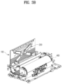
- FIGS. 3A and 3B are a front perspective view and a rear perspective view showing the inside of the display device 1000.
- FIGS. 3A and 3B show the display device 1000 except for a side fixing frame 520 in FIG. 2 .
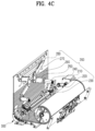
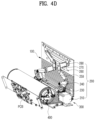
- FIGS. 4A to 4D are a front perspective view and a rear perspective view showing the inside of the display device 1000.
- FIGS. 4A to 4D show a state of the display device 1000 except for a bracket (or frame), a screw, a clip, a rod (or bar), etc. for fixing a bottom fixing frame 530 and other parts in FIGS. 3A and 3B .
- each diagram may represent a flexible display device for a vehicle according to embodiments of the present disclosure.
- the display device 1000 may include a casing having an opening, a display part 100 to be retracted or extended into or out of the casing through the opening, a display driver 200 for moving the display part 100, a guide part 300 for guiding the display part 100, and a display winder 400 for winding the display part 100.
- the casing may include the side casing 10 and the upper casing 20, and the side casing 10 and the upper casing 20 may be assembled together.
- the casing may include an inner space, and thus other components may be placed in the inner space of the casing.
- the casing may include an opening, and the opening may be formed in a size for the display part 100 to be retracted or extended (hereinafter referred to as 'retracted or extended') into or out of the casing.
- the casing may protect the components located in the inner space and improve the appearance of the device.
- the shape of the casing is not limited to that shown in the drawings, and one of ordinary skill in the art to which the present disclosure pertains (hereinafter referred to as 'one of ordinary skill in the art') may appropriately change within the scope of the technical idea of the present disclosure.
- the display part 100 may include components related to a display screen displaying various vehicle-related information.
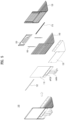
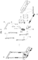
- the display part 100 may include a display 110, a connecting sheet 120, and a display cover 130.
- FIG. 5 is an exploded view of the display part 100 of the display device 1000, and shows components of the display part 100.
- the display 110 may be a flexible or rollable display 110.
- the display 110 may be a plastic organic light-emitting diode (POLED).
- POLED is an OLED applied with a polyimide (PI) substrate, a type of plastic, and may be implemented with a curved surface.
- PI polyimide
- the display 110 may be bent, and a curvature radius at which the display 110 is bent may be at least 50 mm or more. In detail, the radius of curvature of the display 110 may be at least 30 mm or more.
- the display 110 may include a light emitting diode (LED), an OLED, an AMOLED, and a PMOLED.
- the width and height of the display 110 may be appropriately designed by one of ordinary skill in the art.
- the connecting sheet 120 may have one side connected to a lower end of the display 110 and the other side connected to the display winder 400.
- the connecting sheet 120 may be flexible and may be wound or unwound through the display winder 400.
- One side of the connecting sheet 120 may be attached to the display 110 using a double-sided tape.
- the connecting sheet 120 may include a sheet formed of a PET material. The material of the connecting sheet 120 may be appropriately selected by one of ordinary skill in the art in consideration of flexibility.
- the display 110 and the connecting sheet 120 may be connected, and the connecting sheet 120 may be wound or unwound by the display winder 400. Therefore, when the display 110 is retracted into a casing, the display winder 400 may wind the connecting sheet 120, and when the display 110 is extended out of the casing, the display winder 400 may unwind the connecting sheet 120.
- the display cover 130 may be a cover protecting rear surfaces of the display 110 and the connecting sheet 120.
- the display cover 130 may supplement the display 110 and the connecting sheet 120, which do not have rigidity.
- the display cover 130 may include a plurality of covers that are long in a horizontal direction and short in a vertical direction.
- the plurality of covers may be adhered to the rear surface of the display 110 or the rear surface of the connecting sheet 120 through a double-sided adhesive 140.
- the double-sided adhesive 140 may include a double-sided tape such as a FOAM tape.
- the double-sided adhesive 140 may be separately applied to the plurality of covers of the display cover 130.
- the widths of the plurality of covers of the display cover 130 may be greater than or equal to the width of the display 110.
- the heights of the plurality of covers may be appropriately designed by one of ordinary skill in the art in consideration of whether to flexibly respond to bending of the display 110.
- the display cover 130 may further include a magnetism part 160 at both ends in a horizontal direction.
- the magnetism part 160 may utilize a magnetic force for attachment to and detachment from a rear protection cover 2210 (refer to FIG. 18 ) to be described later.
- a rear protection cover 2210 (refer to FIG. 18 )
- an externally exposed portion of the display part 100 may be protected by attaching the rear protection cover 2210 (refer to FIG. 18 ), and an inner portion of the casing of the display part 100 may be separated from the rear protection cover 2210 (refer to FIG. 18 ).
- the display part 100 may further include an upper fixing plate 150, a top fixing clip 152, and a connection reinforcing part 170.
- the upper fixing plate 150 may be a flat plate in surface contact with a part of an upper end of the rear surface of the display 110.
- a width of the upper fixing plate 150 may be at least equal to or greater than a width of the display 110.
- the top fixing clip 152 may be connected to the upper fixing plate 150 at an upper end of a front surface of the display 110.
- An upper end of the display 110 may be fixed by connecting the top fixing clip 152 and the upper fixing plate 150.
- the upper fixing plate 150 and the top fixing clip 152 may protect the upper end of the flexible display 110, and the upper fixing plate 150 may be connected to the display driver 200 to be described later to receive power of a motor.
- the upper fixing plate 150 and the top fixing clip 152 may improve the appearance of the display device.
- the material of the upper fixing plate 150 and the top fixing clip 152 includes aluminum (AL), and other materials having appropriate rigidity may be applied thereto by one of ordinary skill in the art.
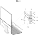
- connection reinforcing part 170 is a component for overcoming the vulnerability of a connection part between the display 110 and an sPCB.
- FIG. 6 is an enlarged view of a lower connection portion of the display 110 to explain the connection reinforcing part 170.
- the display 110 may be connected to a sPCB through a flexible flat cable (FFC), and the FFC may be damaged by an external force when the display 110 is moved. Therefore, the connection reinforcing part 170 may protect the FFC by fixing the FFC on front and rear surfaces of the display 110 or the connecting sheet 120.
- the connection reinforcing part 170 two members having a length in a horizontal direction may be coupled to each other at the front and rear surfaces of the display 110 with the display 110 therebetween. By coupling the two members, the FFC may be fixed, and may be maintained in a shape that is not subjected to an external force. Coupling of the two members may be performed through a double-sided tape or screw fastening.
- the display 110 may be connected to an sPCB and a cPCB, and final control may be performed by a main PCB.
- the display driver 200 is a component moving the display part 100.
- FIG. 7 is an exploded view of the display driver 200.
- the configuration of the display driver 200 may be referred to FIGS. 4C and 4D .
- the display driver 200 may include a motor 210 connected to the inside of a casing, a worm gear part 230 connected to the motor 210, a worm wheel part 240 connected to the worm gear part 230, a first driving arm 250 connected to the worm wheel part 240, and a second driving arm 270 connected to the first driving arm 250.
- Rotation of the motor 210 may be controlled by a controller (not shown). For example, an operation of the motor 210 may be controlled to appropriately retract or extend the display part 100.
- the display part 100 may have different levels of exposure extended to the outside of the casing depending on an exposure mode, and the motor 210 may adjust an exposure range of the display part 100 by controlling an operation according to an exposure mode selected by a user.
- the motor 210 may be a stepping or hybrid motor.
- the worm gear part 230 may include a rod rotating on a rotation shaft parallel to the motor 210 and a worm gear connected to the rod.
- the worm gear part 230 may rotate by rotation of the motor 210, and may be connected to the motor 210 through a timing belt 220 and may operate.
- FIG. 9 illustrates a connection portion of the motor 210 of the display driver 200.
- the motor 210 may rotate the rod of the worm gear part 230 using the timing belt 220.
- the worm wheel part 240 may be connected to the worm gear part 230 and include a worm wheel gear having a rotation shaft perpendicular to the rotation shaft of the motor 210 or the worm gear part 230. As shown in FIG. 4C , since a rotation shaft of the motor 210 is horizontal to the left and right of the display device 1000, a rotation shaft of the worm wheel part 240 may be perpendicular to an exposed surface of the display 110. The worm wheel part 240 may rotate on a virtual plane parallel to the plane of the display 110 by rotation of the motor 210.
- the first driving arm 250 may have one end connected to the worm wheel part 240 and pivot according to rotation of the worm wheel part 240.
- the first driving arm 250 may be an arm member having a predetermined length and may pivot on a virtual plane parallel to an exposed surface of the display part 100.
- the first driving arm 250 may be located adjacent to a rear surface of the display part 100.
- One end of the second driving arm 270 may be pivotably connected to the other end of the first driving arm 250, and the other end of the second driving arm 270 may be pivotably connected to an upper end of the display part 100.
- the first driving arm 250 and the second driving arm 270 may be connected in the form of meshing teeth as shown in the drawing.
- a connecting portion of the first driving arm 250 and the second driving arm 270 may be connected to a gear (e.g., a spur gear), and thus when the first driving arm 250 pivots, the second driving arm 270 may also pivot. Accordingly, the second driving arm 270 may pivot according to rotation of the worm wheel part 240.
- the second driving arm 270 may be an arm member having a predetermined length and may pivot on a virtual plane parallel to an exposed surface of the display part 100. That is, the second driving arm 270 may pivot on the same plane as a pivoting plane of the first driving arm 250. However, the second driving arm 270 may pivot in a direction opposite to that of the first driving arm 250. For example, when the first driving arm 250 pivots clockwise, the second driving arm 270 may pivot counterclockwise.
- the second driving arm 270 may be positioned adjacent to the rear surface of the display part 100, and movement of the second driving arm 270 may be guided by a guide provided in the upper fixing plate 150.
- the upper fixing plate 150 may have a groove for guiding the second driving arm 270.
- the upper fixing plate 150 may include a groove for guiding the first driving arm 250.
- the display driver 200 may further include an arm joint 260 for fixing a connection state between the first driving arm 250 and the second driving arm 270.
- the arm joint 260 may ensure that cogwheels of the first drive arm 250 and cogwheels of the second drive arm 270 are well engaged but connection therebetween is not released.
- a joint spacer 262 may be added to a connection portion between the first driving arm 250, the second driving arm 270, and the arm joint 260 to remove a gap formed by an assembly step.
- the joint spacer 262 may be positioned in an interval between the first driving arm 250 and the arm joint 260 and between the second driving arm 270 and the arm joint 260, and thus the aforementioned gap may be removed.
- the joint spacer 262 may minimize a front-back tilt of the display part 100 that may occur in a situation in which the display part 100 is extended to the maximum.
- the worm wheel part 240, the first driver 250, and the second driver 270 may be provided symmetrically left and right with respect to the center of the display part 100. That is, the display driver 200 may include a pair of first driving parts 250 that are left and right symmetric, a pair of second driving parts 270 that are left and right symmetric, and a pair of the worm wheel parts 240 that are left and right symmetric.
- rotation directions of the pair of first drivers 250 are opposite to each other, and rotation directions of the pair of second drivers 270 are opposite to each other.
- the other ends of the pair of second drivers 270 may be rotatably connected to the upper end of the display part 100, and the upper arm joint 280 for connecting the second driver 270 to the upper end of the display part 100 may be provided.
- the upper arm joint 280 may have a predetermined length in a horizontal direction, and both ends thereof may be rotatably connected to the other ends of the pair of second drivers 270, respectively.
- the upper arm joint 280 may be connected to an upper end of the upper fixing plate 150 of the display part 100.
- the first driver 250 and the second driver 270 may include a metal material and may be formed of aluminum (AL).
- Materials of the arm joint 260 and the upper arm joint 280 may include steel electrolytic cold commercial (SECC) or SUM specified in the Korean Industrial Standards (KS).
- SECC steel electrolytic cold commercial
- KS Korean Industrial Standards
- a material of the joint spacer 262 may include PET.
- a material of the worm wheel gear may include Polyoxymethylene (POM), and a material of the worm gear may include brass.
- FIG. 8 is a diagram to explain an operation process of the display driver 200 of the display device 1000.
- FIG. 8A shows the display driver 200 in a state in which the display part 100 is not exposed
- FIG. 8B shows the display driver 200 in a state in which the display part 100 is exposed to the maximum.
- rotation of the motor 210 may cause the worm gear part 230 to rotate.
- the pair of the worm wheel part 240 may rotate clockwise and counterclockwise, respectively.
- the pair of first driving parts 250 each rotate in the same direction as the pair of the worm wheel parts 240. Therefore, the other end (connection portion with the second driver) of the first driver 250 gradually rises upward, and the second driver 270 connected to the first driver 250 rotates in an opposite direction to a direction of rotation of the first driver 250.
- the other end (a connection portion of the upper arm joint 280) of the second driver 270 is rotatably connected to a point at an upper end of a rear surface of the display part 100. Accordingly, the second driver 270 may raise the display part 100.
- a process of retracting the display part 100 from FIG. 8B to FIG. 8A may be performed by rotating the motor 210 in an opposite direction to the above description.
- FIG. 10 is an exploded view of the guide part 300 of the display device 1000, and FIG. 11 shows arrangement of the guide part 300.
- the guide part 300 is connected to the inside of a casing and is a component that guides movement of the display part 100.
- the guide part 300 may guide the display part 100 to have a path along which the display part 100 moves and which has a curvature radius in a range of 30 mm to 70 mm.
- the guide part 300 may guide the display part 100 to have a path along which the display part 100 moves and which has a curvature radius R in a range of 45 mm to 55 mm.
- the display part 100 may be bent according to the curvature radius guided by the guide part 300 as being retracted or extended into or out of the casing.
- the guide part 300 may include a curvature guide for guiding a movement path in which a curvature radius is formed, and the curvature guide may include a front curvature guide 310 in contact with a front surface of the display part 100, and a rear curvature guide 320 in contact with a rear surface of the display part 100.
- the front curvature guide 310 and the rear curvature guide 320 may include a plurality of rollers. The size and shape of the roller may be appropriately selected by one of ordinary skill in the art.
- the curvature guide of the guide part 300 may include a plurality of rollers connected to a guide fixing bar 312 disposed in left and right directions in an inner space of the casing, or may include a plurality of rollers fixed to various frames or brackets of the part fixing part 500 (refer to FIG. 15 ) inside the casing.
- the guide part 300 may further include a first straight guide 330 and a second straight guide 340 that guide the display part 100 in a vertical or horizontal direction.
- the first straight guide 330 guides the display part 100 in a vertical direction
- the second straight guide 340 guides the display part 100 in a horizontal direction.
- a material of the plurality of rollers may include rubber or polyoxymethylene (POM).
- a material of the frame or bracket for fixing the rollers may include steel electrolytic cold commercial (SECC) or SUM specified in the Korean Industrial Standards (KS).
- the guide part 300 may also function as a guide in a manner different from that shown in the drawings.
- One of ordinary skill in the art may apply a known guide method, and the guide part 300 of the present specification may include a known guide method.
- FIG. 12 is an exploded view of the display winder 400 of the display device 1000.
- the display winder 400 is a component for winding the display part 100 according to retraction and extension of the display part 100.
- the display winder 400 may include a rotary drum 410 and a sensor recognizer 470 for detecting a rotation state of the rotary drum 410.
- the rotary drum 410 rotates around a drum shaft 420 installed in left and right horizontal directions inside a casing as a rotation shaft.
- the rotary drum 410 may have a cylindrical shape, and the display part 100 may be wound or unwound again on an outer circumferential surface of the cylindrical shape.
- the rotary drum 410 may include a rotary spring 450.
- the rotary spring 450 applies an elastic force for the rotary drum 410 to rotate in a direction in which the display part 100 is wound. Therefore, the display part 100 may be pulled downward by the elastic force applied by the rotary spring 450, and a display screen may be maintained flat by a tensile force that pulls the display part 100.
- the rotary drum 410 may further include a spring case 460, a cap 440, and a holder 430.
- the spring case 460 may be a case having an inner space containing the rotary spring 450, and the cap 440 may cover one surface of the spring case 460 containing the rotary spring 450.
- the holder 430 may be a component that fixes the positions of the components (spring case and cap) related to the rotary spring 450.
- the sensor recognizer 470 detects a rotation state of the rotary drum 410.
- the sensor recognizer 470 may include a plurality of sensors 472 and a detection part 474 sensed by the plurality of sensors.
- the detection part 474 may rotate with the rotary drum 410 and may be detected by at least one sensor among the plurality of sensors 472.
- Sensing states of the plurality of sensors 472 may be different according to a rotation state of the rotary drum 410, and an operation of the motor 210 may be controlled based on the sensing state of the plurality of sensors 472. In other words, based on the rotation state of the rotary drum 410, one of the plurality of sensors 472 may recognize a state different from the other sensors, and the operation of the motor 210 may be controlled accordingly.
- a material of the rotary drum 410 may include acrylonitrile butadiene styrene (ABS), a material of the spring case 460, the cap 440, and the holder 430 may include polyoxymethylene (POM), and a material of the rotary spring 450 may include SUS.
- a material of a bracket related to the display winder 400 may include steel electrolytic cold commercial (SECC).
- FIG. 13 is a diagram to explain exposure control of a display according to rotation of the display winder 400.
- the plurality of sensors 472 are fixed to a position at which rotation of the rotary drum 410 is to be detected.
- the plurality of sensors 472 may be fixed to an inner side of a casing adjacent to the rotary drum 410. That is, the sensor 472 may not rotate with the rotary drum 410.
- the detection part 474 is connected to the rotary drum 410 and rotates together, and a shape of the detection part 474 is provided to differently sense any one of the plurality of sensors 472 and the other sensors.
- the plurality of sensors 472 includes a first sensor, a second sensor, a third sensor, and a fourth sensor
- the detection part 474 is provided as a wheel cap covering an end surface of the rotary drum 410, and the wheel cap includes a hole 476 to be recognized by the sensor 472.
- the sensor 472 may include a photosensor.
- a first mode is a state in which the display part 100 is retracted and the rotary drum 410 winds the display part 100 to the maximum.
- the display driver 200 drives the motor 210 to extend the display part 100, and the rotary drum 410 rotates accordingly.
- the plurality of sensors 472 may recognize that a state of the second mode is entered using the detection part 474 rotating with the rotary drum 410. That is, sensing states of a specific one sensor representing the second mode and the other sensors among the plurality of sensors 472 becomes a different state. Accordingly, the display device 1000 may be recognized to become in the second mode and an operation of the motor 210 may be stopped.
- the display driver 200 may drive the motor 210 to further extend the display part 100, and when the sensor recognizer 470 recognizes that the third mode is entered, driving of the motor 210 may be stopped.
- the display device 1000 may differently control a degree of exposure of the display part 100 according to various modes.
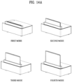
- An exposure mode of the display part 100 may be divided into four modes including the first mode in which the display part 100 is completely retracted into the casing and the fourth mode in which the display part 100 is completely extended out of the casing.
- Each mode may be classified according to a type and function of information displayed on the display 110.
- the third mode may be used on a navigation screen, and the fourth mode may be used when a video or game is played.
- FIG. 14A shows a degree of exposure of the display part 100 according to the first to fourth modes.
- FIGS. 14B and 14C show states of the first driving arm 250 and the second driving arm 270 for each exposure mode as numerical values.
- portions marked with dotted lines represent initial states (first mode).
- FIG. 15 is an exploded view of a component fixing part 500 of the display device 1000.
- the component fixing part 500 is located inside a casing and includes a frame, a rod, etc. for fixing the aforementioned components to a specific location or maintaining a shape of a case.
- the component fixing part 500 may include an interval adjustment rod 510, the side fixing frame 520, the bottom fixing frame 530, a first driver support frame 540, a second driver support frame 542, and a PCB support frame 550.
- the component fixing part 500 may fix a cPCB and a main PCB to the frame.
- the interval adjustment rod 510 is a rod arranged horizontally to the left and right inside the casing.
- the interval adjustment rod 510 may be plural, and may be provided at an appropriate position to fix shapes of the frames.
- the side fixing frame 520 is a flat frame positioned adjacent to a left or right surface inside the casing
- the bottom fixing frame 530 is a flat frame positioned adjacent to a lower surface inside the casing.
- the first driver support frame 540 and the second driver support frame 542 are frame components for supporting or fixing components corresponding to the display driver 200.
- the PCB support frame 550 is a frame component for fixing a PCB.
- a material of the component fixing part 500 may include steel electrolytic cold commercial (SECC) or SUS.
- FIGS. 16 to 20 are diagrams for explaining a display device 2000 according to another embodiment of the present disclosure.
- FIG. 16 is a front perspective view of the display device 2000
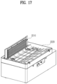
- FIG. 17 is a rear perspective view of the display device 2000 in a state in which an upper cover is removed.
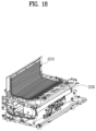
- FIG. 18 is a rear perspective view of the inside of a casing of the display device 2000.
- the display device 2000 according to another embodiment of the present disclosure is different from the display device 1000 in that the display device 2000 further includes a rear cover part 2200.
- the same components as those of the aforementioned display device 1000 will be described using the same reference numerals.
- the rear cover part 2200 may cover a rear surface of the display part 100 and the display driver 200 (a first driving arm or a second driving arm) exposed to the outside to protect the components and improve the appearance of the device.
- FIG. 19 is an exploded view of the rear cover part 2200 of the display device 2000.
- the rear cover part 2200 may include the rear protection cover 2210, an upper cover guide part 2220, and a lower cover guide part 2230.
- the rear protection cover 2210 is attachable to or detachable from a rear surface of the display part 100 and covers an exposed rear surface of the display part 100.
- the rear protection cover 2210 may include a rear detachable cover 2212, a magnetism part 2216, a double-sided adhesive 2218, and a cover reinforcement sheet 2214.
- the rear detachable cover 2212 is a cover that protects a rear surface of the display part 100 or an exposed portion of the display driver 200.
- the rear detachable cover 2212 may include a plurality of covers that are long in a horizontal direction and short in a vertical direction.
- the plurality of covers may be attached to one surface of the cover reinforcement sheet 2214 through the double-sided adhesive 2218.
- the double-sided adhesive 2218 may include a double-sided tape such as a FOAM tape. Widths of the plurality of covers included in the rear detachable cover 2212 may be less than or equal to the width of the display part 100.
- the heights of the plurality of covers may be appropriately designed by one of ordinary skill in the art to a height for flexibly responding to bending.
- the rear detachable cover 2212 may further include the magnetism part 2216 at both ends in a horizontal direction.
- the magnetism part 2216 includes a magnet to attach to and detach from the display part 100.
- the display cover 130 of the display part 100 may be provided with the magnetism part 160 at both left and right ends, and the magnetism part 160 of the display cover 130 and the magnetism part 2216 of the rear detachable cover 2212 may be attached to or detached from each other by magnets.
- the display cover 130 of the display part 100 and the rear protection cover 2210 may have a plurality of magnets arranged in a vertical direction (or a retraction or extension direction of the display part) at positions corresponding to each other.
- the rear protection cover 2210 is separated from the display part 100 when the display part 100 is retracted into the casing, and magnetically attached to the exposed rear surface of the display part 100 when the display part 100 is extended out of the casing.
- FIG. 20 shows a cross section of a connection portion of the rear protection cover 2210 and the display part 100 in detail.
- the magnetism part 2216 is provided at both left and right ends of the rear detachable cover 2212, and a position of the magnetism part 2216 corresponds to the position of the magnetism part 160 provided in the display cover 130.
- the upper cover guide part 2220 and the lower cover guide part 2230 may guide the rear protection cover 2210 separated from the display part 100.
- the upper cover guide part 2220 comes into contact with an outer surface (the outside) of the rear protection cover 2210 to guide the rear protection cover 2210
- the lower cover guide part 2230 comes into contact with an inner surface (the inside) of the rear protection cover 2210 to guide the rear protection cover 2210. That is, movement of the separated rear protection cover 2210 is guided along a space between the upper cover guide part 2220 and the lower cover guide part 2230.
- the inner surface of the rear protection cover 2210 represents a surface facing the display part 100
- the outer surface of the rear protection cover 2210 represents a surface facing an opposite direction to the inner surface.
- the display device 2000 may have an internal space for embedding the rear protection cover 2210 at the top, and the rear protection cover 2210 may be extended out of the casing or retracted into the internal space of the casing.
- the upper cover guide part 2220 and the lower cover guide part 2230 may have shapes including curved surfaces.
- the rear protection cover 2210 may be guided between a lower surface of the upper cover guide part 2220 and an upper surface of the lower cover guide part 2230 along the curved surfaces provided in the respective surfaces.
- the curved surfaces of the upper cover guide part 2220 and the lower cover guide part 2230 may have appropriate curves for the rear protection cover 2210 to be bent within a bending range.
- the rear cover part 2200 may further include a cover guide roller 2240 fixed to the inside of the casing to guide the rear protection cover 2210 and a bracket 2242 supporting the cover guide roller 2240.
- the casing of the rear cover part 2200 may further include an upper cover 2250 and a cover fixture 2260 for fixing the upper cover 2250.
- a material of the rear detachable cover 2212 may include polycarbonate (PC) or aluminum.
- a material of the cover reinforcement sheet 2214 may include polyethylene terephthalate (PET).
- Materials of the upper cover guide part 2220, the lower cover guide part 2230, and the upper cover 2250 may include acrylonitrile butadiene styrene (ABS).
- a material of the cover guide roller 2240 may include rubber, and a material of the bracket 2242 may include steel electrolytic cold commercial (SECC).
- the rear cover part 2200 may have a structure to be disassembled or assembled in the display device 2000, and whether or not to apply the rear cover part 2200 may be selected according to user preference or a vehicle environment.
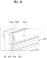
- FIG. 21 is a cross-sectional view of the rear protection cover 2210 coupled to the display part 100 to show a connection relationship between the rear protection cover 2210 and the display part 100.
- the rear protection cover 2210 may be fixed to an upper end of the display part 100.
- the rear protection cover 2210 may include upper fixing parts 2219a, 2219b, and 2219c, and the upper fixing part of the rear protection cover 2210 may be connected to the upper arm joint 280 (refer to FIG. 7 ) of the display device.
- the upper fixing part of the rear protection cover 2210 may be connected to the upper fixing plate 150 (refer to FIG. 5 ) of the display device.
- Various well-known methods for fixing the upper fixing part of the rear protection cover 2210 to the upper arm joint 280 or the upper fixing plate 150 may be applied.
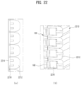
- FIG. 22 is a cross-sectional view of the rear protection cover 2210 to show a connection relationship between components of the rear protection cover 2210.
- FIG. 22A shows a vertical cross section of a central portion of the rear protection cover 2210.
- FIG. 22A shows a cross section in which the rear detachable cover 2212, the double-sided adhesive 2218, and the cover reinforcement sheet 2214 are coupled. That is, the rear detachable cover 2212 may be connected to the cover reinforcement sheet 2214 by the double-sided adhesive 2218.
- FIG. 22B shows a vertical cross section of both left and right ends of the rear protection cover 2210.
- FIG. 22B shows a state in which the display part 100 of the display device and the rear protection cover 2210 are coupled by a magnetic force. Since the magnetism part 160 of the display part 100 and the magnetism part 2216 of the rear protection cover 2210 are attracted to each other by a magnetic force, the rear protection cover 2210 may be attached to and detached from a rear surface of the display part 100.
- the rear protection cover 2210 is separated from the display part 100 when the display part 100 is retracted into the casing, and is attached to the display part 100 when the display part 100 is extended out of the casing. In a process of the display part 110 being retracted into the casing, the rear protection cover 2210 is guided to be separated from the display part 100 by the upper cover guide part 2220 or the lower cover guide part 2230. Components shown in FIG. 22 have been described above with reference to FIG. 20 , and thus detailed descriptions thereof will be omitted.
- FIG. 23 is a cross-sectional view of the rear cover part 2200 to show a state in which the rear protection cover 2210 and the display part 100 are attached to and detached from each other.
- moving directions of the display part 100 retracted into the casing and the rear protection cover 2210 are different. While the display part 100 moves vertically downward, the rear protection cover 2210 starts to be separated from the display part 100 at a specific point and moves along the cover guides 2220 and 2230.
- the guide may include the upper cover guide part 2220 and the lower cover guide part 2230, and since the corresponding components have been described above with reference to FIG. 20 , a detailed description thereof will be omitted.
- FIG. 24 is a cross-sectional view showing a state of the inside of the rear cover part 2200 according to a degree of exposure of the display part 100. Referring to FIG. 24 , in the first mode, the display part 100 and the rear protection cover 2210 are not exposed to the outside of the casing.
- portions of the display part 100 and the rear protection cover 2210 are exposed.
- a part of the rear protection cover 2210 is attached to the exposed rear surface of the display part 100, and another part of the rear protection cover 2210 is located inside the guide while being separated from the display part 100.
- the third mode represents a state in which the display part 100 is more exposed than in the second mode.
- a rear surface of the display part 100 exposed outside the casing may be protected by the rear protection cover 2210.
- a portion of the rear protection cover 2210 inside the casing may be guided and accommodated in a space between the upper cover guide part 2220 and the lower cover guide part 2230.
- FIG. 25 shows the cover guide roller 2240 of the rear cover part 2200.
- the cover guide roller 2240 is connected to a bracket 2242.
- the bracket 2242 may be fixed in an appropriate position inside a casing.
- the cover guide roller 2240 may guide the rear protection cover 2210 in a section in which the rear protection cover 2210 is separated from the display part 100 and bent.
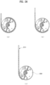
- FIG. 26 shows a cover winder 3300 according to another embodiment of the present disclosure.
- a rear protection cover 3210 may be wound or unwound by the cover winder 3300.
- the cover winder 3300 may be wound on the rear protection cover 3210 while rotating.
- the cover winder 3300 may unwind the rear protection cover 3210 while pivoting in an opposite direction.
- the cover winder 3300 may be fixed to an arbitrary position and may include a rotating rotary drum.
- the cover winder 3300 may include a rotary spring that applies an elastic force in a direction in which the rotary drum winds the rear protection cover 3210.
- a volume of the device required for storing the display may be reduced.
- an exposure range of the display may be controlled by a sensor recognition method appropriately applied to the method of winding the display, and the effectiveness of the display device may be improved. By controlling the exposure range of the display, only an exposed area may be displayed, and power consumption due to use of the display may be reduced.
- the display device may be applied to various positions such as a center, a passenger display, a center console display, a rear seat entertainment display, a rear center display, or a rear control display of a vehicle.
- the usability of an inner space of a vehicle may be increased by reducing the size of an accommodation space for a display.
- the usability of the display may be increased by adjusting a degree of exposure of the display, and power may be saved by using only the exposed portion of a display area.
- a flexible display may be retracted or extended into or out of an accommodation space while being safely protected.
Landscapes
- Engineering & Computer Science (AREA)
- Mechanical Engineering (AREA)
- Chemical & Material Sciences (AREA)
- Combustion & Propulsion (AREA)
- Transportation (AREA)
- Physics & Mathematics (AREA)
- General Physics & Mathematics (AREA)
- Theoretical Computer Science (AREA)
- Microelectronics & Electronic Packaging (AREA)
- Optics & Photonics (AREA)
- Business, Economics & Management (AREA)
- Accounting & Taxation (AREA)
- Marketing (AREA)
- Devices For Indicating Variable Information By Combining Individual Elements (AREA)
Abstract
Description
- This application claims the benefit of earlier filing dates and right of priority to
Korean Application No. 10-2022-0096370, filed on August 02, 2022 - The present embodiments relate to a flexible display device for a vehicle, to be applicable to vehicles in all fields, and more particularly to a device for retracting or extending (hereinafter referred to as 'retracting or extending') a flexible display to be bent or folded.
- A center fascia display of a vehicle may display various visual information about the vehicle. Such a display device may also be installed on a dashboard of a vehicle disposed in front of a driver's seat and a front passenger seat, and provides various convenience information such as navigation, vehicle management and operation, Internet, and entertainment.
- In this regard, there is a movable display device, and the movable display device is capable of moving up and down or left and right relative to a dashboard. As the display moves along a guide, a driver and a passenger may selectively use the display. In the case of a display in the form of a pop-up, the display may be stored and then extended and used when necessary.
- Since an installation position of a fixed display is fixed, the use of space in a vehicle is limited, and as a display size increases, the forward visibility decreases. A pop-up style movable display requires a separate accommodation space for the display, and as the size of the display increases, the size of the accommodation space also increases, limiting the utilization of space in the vehicle. In addition, since an entire screen is operated in an LCD screen display, inefficiency in that all power is used regardless of a degree of exposure of the display remains.
- Therefore, it is required to develop a display device having a form and structure for multiplying advantages while minimizing these disadvantages. Background art related to this may be referred to Patent No.
10-0821925 - An object of the embodiments of the present disclosure is to provide a display device for reducing the size of an accommodation space of a display used in a vehicle.
- An object of the present disclosure is to provide a display device for efficiently retracting or extending a display used in a vehicle from an accommodation space.
- An object of embodiments of the present disclosure is to provide a display device for controlling a degree of exposure of a display according to a purpose of using a display.
- In addition, an object of embodiments of the present disclosure is to provide a display device for saving power for outputting a display image.
- It will be appreciated by one of ordinary skill in the art that the objects that could be achieved with the present disclosure are not limited to what has been particularly described hereinabove and the above and other objects that the present disclosure could achieve will be more clearly understood from the following detailed description.
- According to embodiments of the present disclosure, a flexible display device for a vehicle includes a casing having an opening, a display part to be retracted or extended into or out of the casing through the opening, a display driver configured to move the display part, a display winder configured to wind the display part based on movement of the display part, and a rear protection cover attached to or detached from a rear surface of the display part.
- The rear protection cover may be separated from the display part inside the casing.
- The display part and the rear protection cover may include a plurality of magnets provided at related positions in a vertical direction, and the rear protection cover may be attached to and detached from the display part by a magnet.
- The rear protection cover may include a flexible cover reinforcement sheet, and a rear detachable cover adhered to a rear surface of the cover reinforcement sheet by a double-sided adhesive having adhesiveness on both surfaces.
- The flexible display device may further include a cover guide configured to guide an entire or partial part of the rear protection cover separated from the display part.
- The cover guide may include an upper cover guide part configured to guide an outer surface of the rear protection cover, and a lower cover guide part configured to guide an inner surface of the rear protection cover, a predetermined interval may be formed between the upper cover guide part and the lower cover guide part, and the rear protection cover may be guided by the interval.
- The display part may include a flexible display, a flexible connecting sheet having one side connected to the display and a remaining side connected to the display winder, and a display cover adhered to rear surfaces of the display and the connecting sheet, and the connecting sheet may be to be wound on the display winder.
- The flexible display device may further include a guide part connected to an inside of the casing and configured to guide movement of the display part, and the guide part may perform guidance to have a curvature radius of a path along which the display part moves, in a range of 30 mm to 70 mm. The display may be a plastic organic light-emitting diode (POLED).
- The guide part may include a curvature guide configured to guide a movement path in which the curvature radius is formed, and the curvature guide may include a front curvature guide in contact with a front surface of the display part, and a rear curvature guide in contact with a rear surface of the display part. In addition, the front curvature guide and the rear curvature guide may include a plurality of rollers.
- The display driver may include a motor connected to the inside of the casing, a worm gear part connected to the motor and having a rotation shaft parallel to the motor, and a worm wheel part connected to the worm gear part and having a rotation shaft perpendicular to the motor; and the display driver may move the display part by moving the motor.
- The display driver may further include a first driving arm having one end connected to the worm wheel part and a remaining end connected to the display part, and pivoted by the worm wheel part. In addition, the display driver may further include a second driving arm having one end connected to the remaining end of the first driving arm and a remaining end connected to the display part, pivoting on the same plane as a pivoting plane of the first driving arm, and pivoting in an opposite direction to a pivoting direction of the first driving arm.
- The display part may further include an upper fixing in surface contact with a partial region of a rear surface of an upper end of the display, and the upper fixing plate may include a guide configured to guide the first driving arm or the second driving arm.
- The display winder may include a rotary drum having an outer circumferential surface on which the display part is to be wound, and a sensor recognizer configured to detect a rotation state of the rotary drum. The rotary drum may include a rotary spring, and the rotary spring may apply an elastic force in a direction in which the display part is wound. The sensor recognizer may include a plurality of sensors, and a detection part to be detected by at least one of the plurality of sensors, the detection part may rotate with the rotary drum, and any one of the plurality of sensors may recognize a state different from a remaining sensor based on a rotation state of the rotary drum.
- An external exposure range of the display of the display part may be controlled based on a rotation state of the rotary drum recognized by the sensor recognizer.
- An operation of the display driver may be controlled based on a rotation state of the rotary drum recognized by the sensor recognizer.
- According to embodiments of the present disclosure, a flexible display device for a vehicle includes a casing having an opening, a display part to be retracted or extended into or out of the casing through the opening, a display driver configured to move the display part, a display winder configured to wind the display part based on movement of the display part, and a rear protection cover attached to or detached from a rear surface of the display part, wherein the display part includes a flexible plastic organic light-emitting diode (POLED) display.
- According to embodiments of the present disclosure, in a flexible display device for a vehicle, a flexible plastic organic light-emitting diode (POLED) display may be retracted into a casing or extended out of the casing by winding or unwinding the display, and the flexible display device may include a protection cover attached to or detected from a rear surface of the display by a magnetic force.
-
-
FIG. 1 is a perspective view of a flexible display device for a vehicle according to an embodiment of the present disclosure. -
FIG. 2 is a front perspective view showing the inside of a flexible display device for a vehicle according to an embodiment of the present disclosure. -
FIG. 3A is a front perspective view showing the inside of a flexible display device for a vehicle according to an embodiment of the present disclosure. -
FIG. 3B is a rear perspective view showing the inside of a flexible display device for a vehicle according to an embodiment of the present disclosure. -
FIGS. 4A and4B are front perspective views showing the inside of a flexible display device for a vehicle according to an embodiment of the present disclosure. -
FIGS. 4C and4D are rear perspective views showing the inside of a flexible display device for a vehicle according to an embodiment of the present disclosure. -
FIG. 5 is an exploded view of a display part of a display device. -
FIG. 6 is an enlarged view of a connection portion of a display part of a display device. -
FIG. 7 is an exploded view of a display driver of a display device. -
FIG. 8 is a diagram to explain an operation process of a display driver of a display device. -
FIG. 9 illustrates a motor connection portion of a display driver. -
FIG. 10 is an exploded view of a guide part of a display device. -
FIG. 11 shows arrangement of a guide part in a display device. -
FIG. 12 is an exploded view of a display winder of a display device. -
FIG. 13 is a diagram to explain exposure control of a display according to rotation of a display winder. -
FIGS. 14A to 14C are diagrams for explaining movement of a display driver according to an exposure mode of a display. -
FIG. 15 is an exploded view of a component fixing part of a display device. -
FIG. 16 is a front perspective view of a flexible display device for a vehicle according to another embodiment of the present disclosure. -
FIG. 17 is a rear perspective view of a flexible display device for a vehicle according to another embodiment of the present disclosure. -
FIG. 18 is a rear perspective view showing the inside of a flexible display device for a vehicle according to another embodiment of the present disclosure. -
FIG. 19 is an exploded view of a rear cover part of a flexible display device for a vehicle according to another embodiment of the present disclosure. -
FIG. 20 shows a cross section of a connection portion of a rear protection cover and a display part. -
FIG. 21 shows a cross section of a display part and a rear protection cover to show a connection relationship between a rear protection cover and a display part. -
FIG. 22 is a cross-sectional view of a rear protection cover to show a connection relationship between components of a rear protection cover. -
FIG. 23 is a cross-sectional view of a rear cover part to show a state in which a rear protection cover and a display part are attached to and detached from each other. -
FIG. 24 is a cross-sectional view showing a state of a rear cover part according to retraction and extension of a display part. -
FIG. 25 shows a cover guide of a rear cover part. -
FIG. 26 shows a cover winder according to another embodiment of the present disclosure. - Advantages and features of the present disclosure, and methods of achieving them may be clear with reference to the detailed description of the following embodiments taken in conjunction with the accompanying drawings. However, the present disclosure is not limited to the embodiments disclosed below, but may be implemented in various different forms, only these embodiments are intended to complete the disclosure of the present disclosure, and are common in the art to which the present disclosure belongs. It is provided to fully inform one of ordinary skill in the art of the scope of the present disclosure, and the present disclosure is only defined by the scope of the claims.
- Terminology used herein is for describing the embodiments and is not intended to limit the present disclosure. In this specification, singular forms also include plural forms unless specifically stated otherwise in a phrase. As used herein, "comprises" and/or "comprising" does not exclude the presence or addition of one or more other elements other than the recited elements. Like reference numerals throughout the specification refer to like elements, and "and/or" includes each and every combination of one or more of the recited elements. Although "first", "second", etc. are used to describe various components, these components are not limited by these terms, of course. These terms are only used to distinguish one component from another. Accordingly, it goes without saying that the first element mentioned below may also be the second element within the technical spirit of the present disclosure.
- Unless otherwise defined, all terms (including technical and scientific terms) used in this specification may be used with meanings commonly understood by one of ordinary skill in the art to which the present disclosure pertains. In addition, terms defined in commonly used dictionaries are not interpreted ideally or excessively unless explicitly specifically defined.
- The spatially relative terms "below", "beneath", "lower", "above", "upper", etc. may be used to easily describe a component's correlation with other components. Spatially relative terms should be understood as including different orientations of elements in use or operation in addition to the orientations shown in the drawings. For example, if a component that is shown in a drawing is inverted, a component described as "below" or "beneath" another component may be placed "above" the other component. Thus, the exemplary term "below" may include directions of both below and above. Components may also be oriented in other orientations, and thus spatially relative terms may be interpreted according to orientation.
-
FIG. 1 is a perspective view of a flexible display device for a vehicle (hereinafter referred to as a 'display device') 1000 according to the present embodiment.FIG. 2 is a front perspective view showing the inside of thedisplay device 1000.FIG. 2 shows thedisplay device 1000 in a state in which aside casing 10 and anupper casing 20 are excluded fromFIG. 1 . -
FIGS. 3A and3B are a front perspective view and a rear perspective view showing the inside of thedisplay device 1000.FIGS. 3A and3B show thedisplay device 1000 except for aside fixing frame 520 inFIG. 2 . -
FIGS. 4A to 4D are a front perspective view and a rear perspective view showing the inside of thedisplay device 1000.FIGS. 4A to 4D show a state of thedisplay device 1000 except for a bracket (or frame), a screw, a clip, a rod (or bar), etc. for fixing abottom fixing frame 530 and other parts inFIGS. 3A and3B . - In the drawings, some components may be omitted to describe components located inside the casing of the
display device 1000, and each diagram may represent a flexible display device for a vehicle according to embodiments of the present disclosure. - Referring to
FIGS. 1 to 4 (4A to 4D), thedisplay device 1000 may include a casing having an opening, adisplay part 100 to be retracted or extended into or out of the casing through the opening, adisplay driver 200 for moving thedisplay part 100, aguide part 300 for guiding thedisplay part 100, and adisplay winder 400 for winding thedisplay part 100. - The casing may include the
side casing 10 and theupper casing 20, and theside casing 10 and theupper casing 20 may be assembled together. In addition, the casing may include an inner space, and thus other components may be placed in the inner space of the casing. The casing may include an opening, and the opening may be formed in a size for thedisplay part 100 to be retracted or extended (hereinafter referred to as 'retracted or extended') into or out of the casing. The casing may protect the components located in the inner space and improve the appearance of the device. The shape of the casing is not limited to that shown in the drawings, and one of ordinary skill in the art to which the present disclosure pertains (hereinafter referred to as 'one of ordinary skill in the art') may appropriately change within the scope of the technical idea of the present disclosure. - The
display part 100 may include components related to a display screen displaying various vehicle-related information. For example, thedisplay part 100 may include adisplay 110, a connectingsheet 120, and adisplay cover 130. -
FIG. 5 is an exploded view of thedisplay part 100 of thedisplay device 1000, and shows components of thedisplay part 100. - The
display 110 may be a flexible orrollable display 110. Thedisplay 110 may be a plastic organic light-emitting diode (POLED). The POLED is an OLED applied with a polyimide (PI) substrate, a type of plastic, and may be implemented with a curved surface. - The
display 110 may be bent, and a curvature radius at which thedisplay 110 is bent may be at least 50 mm or more. In detail, the radius of curvature of thedisplay 110 may be at least 30 mm or more. Thedisplay 110 may include a light emitting diode (LED), an OLED, an AMOLED, and a PMOLED. The width and height of thedisplay 110 may be appropriately designed by one of ordinary skill in the art. - The connecting
sheet 120 may have one side connected to a lower end of thedisplay 110 and the other side connected to thedisplay winder 400. In addition, the connectingsheet 120 may be flexible and may be wound or unwound through thedisplay winder 400. One side of the connectingsheet 120 may be attached to thedisplay 110 using a double-sided tape. The connectingsheet 120 may include a sheet formed of a PET material. The material of the connectingsheet 120 may be appropriately selected by one of ordinary skill in the art in consideration of flexibility. - The
display 110 and the connectingsheet 120 may be connected, and the connectingsheet 120 may be wound or unwound by thedisplay winder 400. Therefore, when thedisplay 110 is retracted into a casing, thedisplay winder 400 may wind the connectingsheet 120, and when thedisplay 110 is extended out of the casing, thedisplay winder 400 may unwind the connectingsheet 120. - The
display cover 130 may be a cover protecting rear surfaces of thedisplay 110 and the connectingsheet 120. Thedisplay cover 130 may supplement thedisplay 110 and the connectingsheet 120, which do not have rigidity. Thedisplay cover 130 may include a plurality of covers that are long in a horizontal direction and short in a vertical direction. The plurality of covers may be adhered to the rear surface of thedisplay 110 or the rear surface of the connectingsheet 120 through a double-sided adhesive 140. The double-sided adhesive 140 may include a double-sided tape such as a FOAM tape. The double-sided adhesive 140 may be separately applied to the plurality of covers of thedisplay cover 130. The widths of the plurality of covers of thedisplay cover 130 may be greater than or equal to the width of thedisplay 110. The heights of the plurality of covers may be appropriately designed by one of ordinary skill in the art in consideration of whether to flexibly respond to bending of thedisplay 110. - The
display cover 130 may further include amagnetism part 160 at both ends in a horizontal direction. Themagnetism part 160 may utilize a magnetic force for attachment to and detachment from a rear protection cover 2210 (refer toFIG. 18 ) to be described later. For example, an externally exposed portion of thedisplay part 100 may be protected by attaching the rear protection cover 2210 (refer toFIG. 18 ), and an inner portion of the casing of thedisplay part 100 may be separated from the rear protection cover 2210 (refer toFIG. 18 ). - The
display part 100 may further include anupper fixing plate 150, atop fixing clip 152, and aconnection reinforcing part 170. - The
upper fixing plate 150 may be a flat plate in surface contact with a part of an upper end of the rear surface of thedisplay 110. A width of theupper fixing plate 150 may be at least equal to or greater than a width of thedisplay 110. Thetop fixing clip 152 may be connected to theupper fixing plate 150 at an upper end of a front surface of thedisplay 110. An upper end of thedisplay 110 may be fixed by connecting thetop fixing clip 152 and theupper fixing plate 150. Theupper fixing plate 150 and thetop fixing clip 152 may protect the upper end of theflexible display 110, and theupper fixing plate 150 may be connected to thedisplay driver 200 to be described later to receive power of a motor. In addition, theupper fixing plate 150 and thetop fixing clip 152 may improve the appearance of the display device. - The material of the
upper fixing plate 150 and thetop fixing clip 152 includes aluminum (AL), and other materials having appropriate rigidity may be applied thereto by one of ordinary skill in the art. - The
connection reinforcing part 170 is a component for overcoming the vulnerability of a connection part between thedisplay 110 and an sPCB. -
FIG. 6 is an enlarged view of a lower connection portion of thedisplay 110 to explain theconnection reinforcing part 170. - The
display 110 may be connected to a sPCB through a flexible flat cable (FFC), and the FFC may be damaged by an external force when thedisplay 110 is moved. Therefore, theconnection reinforcing part 170 may protect the FFC by fixing the FFC on front and rear surfaces of thedisplay 110 or the connectingsheet 120. In theconnection reinforcing part 170, two members having a length in a horizontal direction may be coupled to each other at the front and rear surfaces of thedisplay 110 with thedisplay 110 therebetween. By coupling the two members, the FFC may be fixed, and may be maintained in a shape that is not subjected to an external force. Coupling of the two members may be performed through a double-sided tape or screw fastening. - The
display 110 may be connected to an sPCB and a cPCB, and final control may be performed by a main PCB. - The
display driver 200 is a component moving thedisplay part 100. -
FIG. 7 is an exploded view of thedisplay driver 200. The configuration of thedisplay driver 200 may be referred toFIGS. 4C and4D . - The
display driver 200 may include amotor 210 connected to the inside of a casing, aworm gear part 230 connected to themotor 210, aworm wheel part 240 connected to theworm gear part 230, afirst driving arm 250 connected to theworm wheel part 240, and asecond driving arm 270 connected to thefirst driving arm 250. - Rotation of the
motor 210 may be controlled by a controller (not shown). For example, an operation of themotor 210 may be controlled to appropriately retract or extend thedisplay part 100. Thedisplay part 100 may have different levels of exposure extended to the outside of the casing depending on an exposure mode, and themotor 210 may adjust an exposure range of thedisplay part 100 by controlling an operation according to an exposure mode selected by a user. Themotor 210 may be a stepping or hybrid motor. - The
worm gear part 230 may include a rod rotating on a rotation shaft parallel to themotor 210 and a worm gear connected to the rod. Theworm gear part 230 may rotate by rotation of themotor 210, and may be connected to themotor 210 through atiming belt 220 and may operate. -
FIG. 9 illustrates a connection portion of themotor 210 of thedisplay driver 200. Themotor 210 may rotate the rod of theworm gear part 230 using thetiming belt 220. - The
worm wheel part 240 may be connected to theworm gear part 230 and include a worm wheel gear having a rotation shaft perpendicular to the rotation shaft of themotor 210 or theworm gear part 230. As shown inFIG. 4C , since a rotation shaft of themotor 210 is horizontal to the left and right of thedisplay device 1000, a rotation shaft of theworm wheel part 240 may be perpendicular to an exposed surface of thedisplay 110. Theworm wheel part 240 may rotate on a virtual plane parallel to the plane of thedisplay 110 by rotation of themotor 210. - The
first driving arm 250 may have one end connected to theworm wheel part 240 and pivot according to rotation of theworm wheel part 240. Thefirst driving arm 250 may be an arm member having a predetermined length and may pivot on a virtual plane parallel to an exposed surface of thedisplay part 100. Thefirst driving arm 250 may be located adjacent to a rear surface of thedisplay part 100. - One end of the
second driving arm 270 may be pivotably connected to the other end of thefirst driving arm 250, and the other end of thesecond driving arm 270 may be pivotably connected to an upper end of thedisplay part 100. Thefirst driving arm 250 and thesecond driving arm 270 may be connected in the form of meshing teeth as shown in the drawing. A connecting portion of thefirst driving arm 250 and thesecond driving arm 270 may be connected to a gear (e.g., a spur gear), and thus when thefirst driving arm 250 pivots, thesecond driving arm 270 may also pivot. Accordingly, thesecond driving arm 270 may pivot according to rotation of theworm wheel part 240. - The
second driving arm 270 may be an arm member having a predetermined length and may pivot on a virtual plane parallel to an exposed surface of thedisplay part 100. That is, thesecond driving arm 270 may pivot on the same plane as a pivoting plane of thefirst driving arm 250. However, thesecond driving arm 270 may pivot in a direction opposite to that of thefirst driving arm 250. For example, when thefirst driving arm 250 pivots clockwise, thesecond driving arm 270 may pivot counterclockwise. Thesecond driving arm 270 may be positioned adjacent to the rear surface of thedisplay part 100, and movement of thesecond driving arm 270 may be guided by a guide provided in theupper fixing plate 150. - As shown in
FIG. 4C , theupper fixing plate 150 may have a groove for guiding thesecond driving arm 270. Although not shown, theupper fixing plate 150 may include a groove for guiding thefirst driving arm 250. - The
display driver 200 may further include an arm joint 260 for fixing a connection state between thefirst driving arm 250 and thesecond driving arm 270. The arm joint 260 may ensure that cogwheels of thefirst drive arm 250 and cogwheels of thesecond drive arm 270 are well engaged but connection therebetween is not released. - A
joint spacer 262 may be added to a connection portion between thefirst driving arm 250, thesecond driving arm 270, and the arm joint 260 to remove a gap formed by an assembly step. Thejoint spacer 262 may be positioned in an interval between thefirst driving arm 250 and the arm joint 260 and between thesecond driving arm 270 and the arm joint 260, and thus the aforementioned gap may be removed. Thejoint spacer 262 may minimize a front-back tilt of thedisplay part 100 that may occur in a situation in which thedisplay part 100 is extended to the maximum. - The
worm wheel part 240, thefirst driver 250, and thesecond driver 270 may be provided symmetrically left and right with respect to the center of thedisplay part 100. That is, thedisplay driver 200 may include a pair of first drivingparts 250 that are left and right symmetric, a pair of second drivingparts 270 that are left and right symmetric, and a pair of theworm wheel parts 240 that are left and right symmetric. - At this time, rotation directions of the pair of
first drivers 250 are opposite to each other, and rotation directions of the pair ofsecond drivers 270 are opposite to each other. - The other ends of the pair of
second drivers 270 may be rotatably connected to the upper end of thedisplay part 100, and the upper arm joint 280 for connecting thesecond driver 270 to the upper end of thedisplay part 100 may be provided. The upper arm joint 280 may have a predetermined length in a horizontal direction, and both ends thereof may be rotatably connected to the other ends of the pair ofsecond drivers 270, respectively. The upper arm joint 280 may be connected to an upper end of theupper fixing plate 150 of thedisplay part 100. - The
first driver 250 and thesecond driver 270 may include a metal material and may be formed of aluminum (AL). Materials of the arm joint 260 and the upper arm joint 280 may include steel electrolytic cold commercial (SECC) or SUM specified in the Korean Industrial Standards (KS). A material of thejoint spacer 262 may include PET. A material of the worm wheel gear may include Polyoxymethylene (POM), and a material of the worm gear may include brass. - Hereinafter, movement of the
display driver 200 will be described. -
FIG. 8 is a diagram to explain an operation process of thedisplay driver 200 of thedisplay device 1000.FIG. 8A shows thedisplay driver 200 in a state in which thedisplay part 100 is not exposed, andFIG. 8B shows thedisplay driver 200 in a state in which thedisplay part 100 is exposed to the maximum. - Referring to a process of extending the
display part 100 fromFIG. 8A to FIG. 8B , rotation of themotor 210 may cause theworm gear part 230 to rotate. When theworm gear part 230 rotates, the pair of theworm wheel part 240 may rotate clockwise and counterclockwise, respectively. The pair of first drivingparts 250 each rotate in the same direction as the pair of theworm wheel parts 240. Therefore, the other end (connection portion with the second driver) of thefirst driver 250 gradually rises upward, and thesecond driver 270 connected to thefirst driver 250 rotates in an opposite direction to a direction of rotation of thefirst driver 250. The other end (a connection portion of the upper arm joint 280) of thesecond driver 270 is rotatably connected to a point at an upper end of a rear surface of thedisplay part 100. Accordingly, thesecond driver 270 may raise thedisplay part 100. - A process of retracting the
display part 100 fromFIG. 8B to FIG. 8A may be performed by rotating themotor 210 in an opposite direction to the above description. -
FIG. 10 is an exploded view of theguide part 300 of thedisplay device 1000, andFIG. 11 shows arrangement of theguide part 300. - The
guide part 300 is connected to the inside of a casing and is a component that guides movement of thedisplay part 100. Theguide part 300 may guide thedisplay part 100 to have a path along which thedisplay part 100 moves and which has a curvature radius in a range of 30 mm to 70 mm. In detail, theguide part 300 may guide thedisplay part 100 to have a path along which thedisplay part 100 moves and which has a curvature radius R in a range of 45 mm to 55 mm. Thedisplay part 100 may be bent according to the curvature radius guided by theguide part 300 as being retracted or extended into or out of the casing. - The
guide part 300 may include a curvature guide for guiding a movement path in which a curvature radius is formed, and the curvature guide may include afront curvature guide 310 in contact with a front surface of thedisplay part 100, and arear curvature guide 320 in contact with a rear surface of thedisplay part 100. Thefront curvature guide 310 and therear curvature guide 320 may include a plurality of rollers. The size and shape of the roller may be appropriately selected by one of ordinary skill in the art. - The curvature guide of the
guide part 300 may include a plurality of rollers connected to aguide fixing bar 312 disposed in left and right directions in an inner space of the casing, or may include a plurality of rollers fixed to various frames or brackets of the part fixing part 500 (refer toFIG. 15 ) inside the casing. - In addition, the
guide part 300 may further include a firststraight guide 330 and a secondstraight guide 340 that guide thedisplay part 100 in a vertical or horizontal direction. Referring toFIG. 11 , the firststraight guide 330 guides thedisplay part 100 in a vertical direction, and the secondstraight guide 340 guides thedisplay part 100 in a horizontal direction. - A material of the plurality of rollers may include rubber or polyoxymethylene (POM). In addition, a material of the frame or bracket for fixing the rollers may include steel electrolytic cold commercial (SECC) or SUM specified in the Korean Industrial Standards (KS).
- The
guide part 300 may also function as a guide in a manner different from that shown in the drawings. One of ordinary skill in the art may apply a known guide method, and theguide part 300 of the present specification may include a known guide method. -
FIG. 12 is an exploded view of thedisplay winder 400 of thedisplay device 1000. - The
display winder 400 is a component for winding thedisplay part 100 according to retraction and extension of thedisplay part 100. Thedisplay winder 400 may include arotary drum 410 and asensor recognizer 470 for detecting a rotation state of therotary drum 410. - The
rotary drum 410 rotates around a drum shaft 420 installed in left and right horizontal directions inside a casing as a rotation shaft. In addition, therotary drum 410 may have a cylindrical shape, and thedisplay part 100 may be wound or unwound again on an outer circumferential surface of the cylindrical shape. Therotary drum 410 may include arotary spring 450. Therotary spring 450 applies an elastic force for therotary drum 410 to rotate in a direction in which thedisplay part 100 is wound. Therefore, thedisplay part 100 may be pulled downward by the elastic force applied by therotary spring 450, and a display screen may be maintained flat by a tensile force that pulls thedisplay part 100. - The
rotary drum 410 may further include aspring case 460, acap 440, and aholder 430. Thespring case 460 may be a case having an inner space containing therotary spring 450, and thecap 440 may cover one surface of thespring case 460 containing therotary spring 450. Theholder 430 may be a component that fixes the positions of the components (spring case and cap) related to therotary spring 450. - The
sensor recognizer 470 detects a rotation state of therotary drum 410. thesensor recognizer 470 may include a plurality ofsensors 472 and adetection part 474 sensed by the plurality of sensors. Thedetection part 474 may rotate with therotary drum 410 and may be detected by at least one sensor among the plurality ofsensors 472. - Sensing states of the plurality of
sensors 472 may be different according to a rotation state of therotary drum 410, and an operation of themotor 210 may be controlled based on the sensing state of the plurality ofsensors 472. In other words, based on the rotation state of therotary drum 410, one of the plurality ofsensors 472 may recognize a state different from the other sensors, and the operation of themotor 210 may be controlled accordingly. - A material of the
rotary drum 410 may include acrylonitrile butadiene styrene (ABS), a material of thespring case 460, thecap 440, and theholder 430 may include polyoxymethylene (POM), and a material of therotary spring 450 may include SUS. A material of a bracket related to thedisplay winder 400 may include steel electrolytic cold commercial (SECC). -
FIG. 13 is a diagram to explain exposure control of a display according to rotation of thedisplay winder 400. - Referring to
FIG. 13A , the plurality ofsensors 472 are fixed to a position at which rotation of therotary drum 410 is to be detected. In the present embodiment, the plurality ofsensors 472 may be fixed to an inner side of a casing adjacent to therotary drum 410. That is, thesensor 472 may not rotate with therotary drum 410. - The
detection part 474 is connected to therotary drum 410 and rotates together, and a shape of thedetection part 474 is provided to differently sense any one of the plurality ofsensors 472 and the other sensors. For example, when the plurality ofsensors 472 includes a first sensor, a second sensor, a third sensor, and a fourth sensor, if the first sensor perform recognition (on) using thedetection part 474, the second to fourth sensors may not perform recognition (off). Conversely, the first sensor may not perform recognition (off), and the second to fourth sensors may perform recognition (on). In the present embodiment, thedetection part 474 is provided as a wheel cap covering an end surface of therotary drum 410, and the wheel cap includes ahole 476 to be recognized by thesensor 472. In addition, thesensor 472 may include a photosensor. - When the
rotary drum 410 rotates, a position of thehole 476 also rotates around a rotation shaft, and when thehole 476 passes through one of thesensors 472, the corresponding sensor may recognize a rotation state of therotary drum 410. Therefore, when the rotation state of therotary drum 410 is divided according to modes, an exposure range of thedisplay part 100 may be controlled. - Referring to
FIG. 13B , a first mode is a state in which thedisplay part 100 is retracted and therotary drum 410 winds thedisplay part 100 to the maximum. When a second mode is executed by user selection, thedisplay driver 200 drives themotor 210 to extend thedisplay part 100, and therotary drum 410 rotates accordingly. - At a moment when the
display part 100 is exposed in the second mode, the plurality ofsensors 472 may recognize that a state of the second mode is entered using thedetection part 474 rotating with therotary drum 410. That is, sensing states of a specific one sensor representing the second mode and the other sensors among the plurality ofsensors 472 becomes a different state. Accordingly, thedisplay device 1000 may be recognized to become in the second mode and an operation of themotor 210 may be stopped. - In the case of the third mode, the
display part 100 is exposed more than the second mode. When the third mode is executed by user selection, thedisplay driver 200 may drive themotor 210 to further extend thedisplay part 100, and when thesensor recognizer 470 recognizes that the third mode is entered, driving of themotor 210 may be stopped. - In the same way, the
display device 1000 may differently control a degree of exposure of thedisplay part 100 according to various modes. An exposure mode of thedisplay part 100 may be divided into four modes including the first mode in which thedisplay part 100 is completely retracted into the casing and the fourth mode in which thedisplay part 100 is completely extended out of the casing. Each mode may be classified according to a type and function of information displayed on thedisplay 110. For example, the third mode may be used on a navigation screen, and the fourth mode may be used when a video or game is played. -
FIG. 14A shows a degree of exposure of thedisplay part 100 according to the first to fourth modes. -
FIGS. 14B and14C show states of thefirst driving arm 250 and thesecond driving arm 270 for each exposure mode as numerical values. In the second to fourth modes, portions marked with dotted lines represent initial states (first mode). -
FIG. 15 is an exploded view of acomponent fixing part 500 of thedisplay device 1000. - The
component fixing part 500 is located inside a casing and includes a frame, a rod, etc. for fixing the aforementioned components to a specific location or maintaining a shape of a case. Thecomponent fixing part 500 may include aninterval adjustment rod 510, theside fixing frame 520, thebottom fixing frame 530, a firstdriver support frame 540, a seconddriver support frame 542, and aPCB support frame 550. Thecomponent fixing part 500 may fix a cPCB and a main PCB to the frame. - The
interval adjustment rod 510 is a rod arranged horizontally to the left and right inside the casing. Theinterval adjustment rod 510 may be plural, and may be provided at an appropriate position to fix shapes of the frames. - The
side fixing frame 520 is a flat frame positioned adjacent to a left or right surface inside the casing, and thebottom fixing frame 530 is a flat frame positioned adjacent to a lower surface inside the casing. - The first
driver support frame 540 and the seconddriver support frame 542 are frame components for supporting or fixing components corresponding to thedisplay driver 200. - The
PCB support frame 550 is a frame component for fixing a PCB. - A material of the
component fixing part 500 may include steel electrolytic cold commercial (SECC) or SUS. -
FIGS. 16 to 20 are diagrams for explaining adisplay device 2000 according to another embodiment of the present disclosure. -
FIG. 16 is a front perspective view of thedisplay device 2000, andFIG. 17 is a rear perspective view of thedisplay device 2000 in a state in which an upper cover is removed.FIG. 18 is a rear perspective view of the inside of a casing of thedisplay device 2000. - The
display device 2000 according to another embodiment of the present disclosure is different from thedisplay device 1000 in that thedisplay device 2000 further includes arear cover part 2200. In describing thedisplay device 2000, the same components as those of theaforementioned display device 1000 will be described using the same reference numerals. - The
rear cover part 2200 may cover a rear surface of thedisplay part 100 and the display driver 200 (a first driving arm or a second driving arm) exposed to the outside to protect the components and improve the appearance of the device. -
FIG. 19 is an exploded view of therear cover part 2200 of thedisplay device 2000. - The
rear cover part 2200 may include therear protection cover 2210, an uppercover guide part 2220, and a lowercover guide part 2230. - The
rear protection cover 2210 is attachable to or detachable from a rear surface of thedisplay part 100 and covers an exposed rear surface of thedisplay part 100. - The
rear protection cover 2210 may include a reardetachable cover 2212, amagnetism part 2216, a double-sided adhesive 2218, and acover reinforcement sheet 2214. - The rear
detachable cover 2212 is a cover that protects a rear surface of thedisplay part 100 or an exposed portion of thedisplay driver 200. The reardetachable cover 2212 may include a plurality of covers that are long in a horizontal direction and short in a vertical direction. The plurality of covers may be attached to one surface of thecover reinforcement sheet 2214 through the double-sided adhesive 2218. The double-sided adhesive 2218 may include a double-sided tape such as a FOAM tape. Widths of the plurality of covers included in the reardetachable cover 2212 may be less than or equal to the width of thedisplay part 100. The heights of the plurality of covers may be appropriately designed by one of ordinary skill in the art to a height for flexibly responding to bending. - The rear
detachable cover 2212 may further include themagnetism part 2216 at both ends in a horizontal direction. Themagnetism part 2216 includes a magnet to attach to and detach from thedisplay part 100. Thedisplay cover 130 of thedisplay part 100 may be provided with themagnetism part 160 at both left and right ends, and themagnetism part 160 of thedisplay cover 130 and themagnetism part 2216 of the reardetachable cover 2212 may be attached to or detached from each other by magnets. - The
display cover 130 of thedisplay part 100 and therear protection cover 2210 may have a plurality of magnets arranged in a vertical direction (or a retraction or extension direction of the display part) at positions corresponding to each other. Therear protection cover 2210 is separated from thedisplay part 100 when thedisplay part 100 is retracted into the casing, and magnetically attached to the exposed rear surface of thedisplay part 100 when thedisplay part 100 is extended out of the casing. -
FIG. 20 shows a cross section of a connection portion of therear protection cover 2210 and thedisplay part 100 in detail. As shown inFIG. 20 , themagnetism part 2216 is provided at both left and right ends of the reardetachable cover 2212, and a position of themagnetism part 2216 corresponds to the position of themagnetism part 160 provided in thedisplay cover 130. - The upper
cover guide part 2220 and the lowercover guide part 2230 may guide therear protection cover 2210 separated from thedisplay part 100. The uppercover guide part 2220 comes into contact with an outer surface (the outside) of therear protection cover 2210 to guide therear protection cover 2210, and the lowercover guide part 2230 comes into contact with an inner surface (the inside) of therear protection cover 2210 to guide therear protection cover 2210. That is, movement of the separatedrear protection cover 2210 is guided along a space between the uppercover guide part 2220 and the lowercover guide part 2230. The inner surface of therear protection cover 2210 represents a surface facing thedisplay part 100, and the outer surface of therear protection cover 2210 represents a surface facing an opposite direction to the inner surface. - The
display device 2000 may have an internal space for embedding therear protection cover 2210 at the top, and therear protection cover 2210 may be extended out of the casing or retracted into the internal space of the casing. - The upper
cover guide part 2220 and the lowercover guide part 2230 may have shapes including curved surfaces. Therear protection cover 2210 may be guided between a lower surface of the uppercover guide part 2220 and an upper surface of the lowercover guide part 2230 along the curved surfaces provided in the respective surfaces. The curved surfaces of the uppercover guide part 2220 and the lowercover guide part 2230 may have appropriate curves for therear protection cover 2210 to be bent within a bending range. - In addition, the
rear cover part 2200 may further include acover guide roller 2240 fixed to the inside of the casing to guide therear protection cover 2210 and abracket 2242 supporting thecover guide roller 2240. - The casing of the
rear cover part 2200 may further include anupper cover 2250 and acover fixture 2260 for fixing theupper cover 2250. - A material of the rear
detachable cover 2212 may include polycarbonate (PC) or aluminum. A material of thecover reinforcement sheet 2214 may include polyethylene terephthalate (PET). Materials of the uppercover guide part 2220, the lowercover guide part 2230, and theupper cover 2250 may include acrylonitrile butadiene styrene (ABS). A material of thecover guide roller 2240 may include rubber, and a material of thebracket 2242 may include steel electrolytic cold commercial (SECC). - The
rear cover part 2200 may have a structure to be disassembled or assembled in thedisplay device 2000, and whether or not to apply therear cover part 2200 may be selected according to user preference or a vehicle environment. -
FIG. 21 is a cross-sectional view of therear protection cover 2210 coupled to thedisplay part 100 to show a connection relationship between therear protection cover 2210 and thedisplay part 100. - Referring to
FIG. 21 , therear protection cover 2210 may be fixed to an upper end of thedisplay part 100. Therear protection cover 2210 may includeupper fixing parts rear protection cover 2210 may be connected to the upper arm joint 280 (refer toFIG. 7 ) of the display device. In addition, the upper fixing part of therear protection cover 2210 may be connected to the upper fixing plate 150 (refer toFIG. 5 ) of the display device. Various well-known methods for fixing the upper fixing part of therear protection cover 2210 to the upper arm joint 280 or theupper fixing plate 150 may be applied. -
FIG. 22 is a cross-sectional view of therear protection cover 2210 to show a connection relationship between components of therear protection cover 2210. -
FIG. 22A shows a vertical cross section of a central portion of therear protection cover 2210.FIG. 22A shows a cross section in which the reardetachable cover 2212, the double-sided adhesive 2218, and thecover reinforcement sheet 2214 are coupled. That is, the reardetachable cover 2212 may be connected to thecover reinforcement sheet 2214 by the double-sided adhesive 2218. -
FIG. 22B shows a vertical cross section of both left and right ends of therear protection cover 2210.FIG. 22B shows a state in which thedisplay part 100 of the display device and therear protection cover 2210 are coupled by a magnetic force. Since themagnetism part 160 of thedisplay part 100 and themagnetism part 2216 of therear protection cover 2210 are attracted to each other by a magnetic force, therear protection cover 2210 may be attached to and detached from a rear surface of thedisplay part 100. - The
rear protection cover 2210 is separated from thedisplay part 100 when thedisplay part 100 is retracted into the casing, and is attached to thedisplay part 100 when thedisplay part 100 is extended out of the casing. In a process of thedisplay part 110 being retracted into the casing, therear protection cover 2210 is guided to be separated from thedisplay part 100 by the uppercover guide part 2220 or the lowercover guide part 2230. Components shown inFIG. 22 have been described above with reference toFIG. 20 , and thus detailed descriptions thereof will be omitted. -
FIG. 23 is a cross-sectional view of therear cover part 2200 to show a state in which therear protection cover 2210 and thedisplay part 100 are attached to and detached from each other. - Referring to
FIG. 23 , moving directions of thedisplay part 100 retracted into the casing and therear protection cover 2210 are different. While thedisplay part 100 moves vertically downward, therear protection cover 2210 starts to be separated from thedisplay part 100 at a specific point and moves along the cover guides 2220 and 2230. The guide may include the uppercover guide part 2220 and the lowercover guide part 2230, and since the corresponding components have been described above with reference toFIG. 20 , a detailed description thereof will be omitted. -
FIG. 24 is a cross-sectional view showing a state of the inside of therear cover part 2200 according to a degree of exposure of thedisplay part 100. Referring toFIG. 24 , in the first mode, thedisplay part 100 and therear protection cover 2210 are not exposed to the outside of the casing. - In the second mode, portions of the
display part 100 and therear protection cover 2210 are exposed. At this time, a part of therear protection cover 2210 is attached to the exposed rear surface of thedisplay part 100, and another part of therear protection cover 2210 is located inside the guide while being separated from thedisplay part 100. - The third mode represents a state in which the
display part 100 is more exposed than in the second mode. As in the first to third modes, a rear surface of thedisplay part 100 exposed outside the casing may be protected by therear protection cover 2210. A portion of therear protection cover 2210 inside the casing may be guided and accommodated in a space between the uppercover guide part 2220 and the lowercover guide part 2230. -
FIG. 25 shows thecover guide roller 2240 of therear cover part 2200. Referring toFIG. 25 , thecover guide roller 2240 is connected to abracket 2242. Thebracket 2242 may be fixed in an appropriate position inside a casing. Thecover guide roller 2240 may guide therear protection cover 2210 in a section in which therear protection cover 2210 is separated from thedisplay part 100 and bent. -
FIG. 26 shows acover winder 3300 according to another embodiment of the present disclosure. Referring toFIG. 26 , arear protection cover 3210 may be wound or unwound by thecover winder 3300. For example, when therear protection cover 3210 is retracted into a casing, thecover winder 3300 may be wound on therear protection cover 3210 while rotating. When therear protection cover 3210 is extended out of the casing, thecover winder 3300 may unwind therear protection cover 3210 while pivoting in an opposite direction. Thecover winder 3300 may be fixed to an arbitrary position and may include a rotating rotary drum. Thecover winder 3300 may include a rotary spring that applies an elastic force in a direction in which the rotary drum winds therear protection cover 3210. - According to the embodiments of the present disclosure, as a flexible display is retracted or extended into or out of the casing by winding the display, a volume of the device required for storing the display may be reduced. In addition, an exposure range of the display may be controlled by a sensor recognition method appropriately applied to the method of winding the display, and the effectiveness of the display device may be improved. By controlling the exposure range of the display, only an exposed area may be displayed, and power consumption due to use of the display may be reduced.
- The display device according to the embodiments may be applied to various positions such as a center, a passenger display, a center console display, a rear seat entertainment display, a rear center display, or a rear control display of a vehicle.
- It may be understood that the description of the various embodiments of the present disclosure is not limited to the corresponding embodiment, and the technical idea of each embodiment applied in the various embodiments may be applied to other embodiments as well.
- The detailed description of the exemplary embodiments of the present disclosure is given to enable one of ordinary skill in the art to realize and implement the present disclosure. While the present disclosure has been described referring to the exemplary embodiments of the present disclosure, one of ordinary skill in the art will appreciate that many modifications and changes may be made to the present disclosure without departing from the spirit and essential characteristics of the present disclosure. For example, the structures of the above-described embodiments of the present disclosure may be used in combination.
- Therefore, the present disclosure intends not to limit the embodiments disclosed herein but to give a broadest range matching the principles and new features disclosed herein.
- According to any one of the embodiments of the present disclosure, the usability of an inner space of a vehicle may be increased by reducing the size of an accommodation space for a display.
- According to any one of the embodiments of the present disclosure, the usability of the display may be increased by adjusting a degree of exposure of the display, and power may be saved by using only the exposed portion of a display area.
- In addition, according to any one of the embodiments of the present disclosure, a flexible display may be retracted or extended into or out of an accommodation space while being safely protected.
- The effects obtainable in the present disclosure are not limited to the effects mentioned above, and other effects not mentioned are clearly understood by one of ordinary skill in the art from the description above.
Claims (15)
- A flexible display device for a vehicle, comprising:a casing having an opening;a display part to be retracted or extended into or out of the casing through the opening;a display driver configured to move the display part;a display winder configured to wind the display part based on movement of the display part; anda rear protection cover attached to or detached from a rear surface of the display part,wherein the rear protection cover is separated from the display part inside the casing.
- The flexible display device of claim 1, wherein:the display part and the rear protection cover include a plurality of magnets provided at related positions in a vertical direction; andthe rear protection cover is attached to and detached from the display part by a magnet.
- The flexible display device of claim 2, wherein the rear protection cover includes a flexible cover reinforcement sheet, and a rear detachable cover adhered to a rear surface of the cover reinforcement sheet by a double-sided adhesive having adhesiveness on both surfaces.
- The flexible display device of claim 3, further comprising:a cover guide configured to guide an entire or partial part of the rear protection cover separated from the display part,wherein the cover guide includes:an upper cover guide part configured to guide an outer surface of the rear protection cover; anda lower cover guide part configured to guide an inner surface of the rear protection cover;a predetermined interval is formed between the upper cover guide part and the lower cover guide part; andthe rear protection cover is guided by the interval.
- The flexible display device of any one of claims 1 to 4, wherein:
the display part includes:a flexible display;a flexible connecting sheet having one side connected to the display and a remaining side connected to the display winder; anda display cover adhered to rear surfaces of the display and the connecting sheet; andthe connecting sheet is to be wound on the display winder. - The flexible display device of claim 5, further comprising:a guide part connected to an inside of the casing and configured to guide movement of the display part,wherein the guide part performs guidance to have a curvature radius of a path along which the display part moves, in a range of 30 mm to 70 mm,wherein the display is a plastic organic light-emitting diode (POLED).
- The flexible display device of claim 6, wherein:the guide part includes a curvature guide configured to guide a movement path in which the curvature radius is formed; andthe curvature guide includes a front curvature guide in contact with a front surface of the display part, and a rear curvature guide in contact with a rear surface of the display part,wherein the front curvature guide and the rear curvature guide include a plurality of rollers.
- The flexible display device of claim 7, wherein:
the display driver includes:a motor connected to the inside of the casing;a worm gear part connected to the motor and having a rotation shaft parallel to the motor; anda worm wheel part connected to the worm gear part and having a rotation shaft perpendicular to the motor; andthe display driver moves the display part by moving the motor. - The flexible display device of claim 8, wherein the display driver further includes:a first driving arm having one end connected to the worm wheel part and a remaining end connected to the display part, and pivoted by the worm wheel part; anda second driving arm having one end connected to the remaining end of the first driving arm and a remaining end connected to the display part, pivoting on the same plane as a pivoting plane of the first driving arm, and pivoting in an opposite direction to a pivoting direction of the first driving arm,wherein:the display part further includes an upper fixing plate in surface contact with a partial region of a rear surface of an upper end of the display; andthe upper fixing plate includes a guide configured to guide the first driving arm or the second driving arm.
- The flexible display device of any one of claims 1 to 9, wherein the display winder includes:a rotary drum having an outer circumferential surface on which the display part is to be wound; anda sensor recognizer configured to detect a rotation state of the rotary drum,wherein:the rotary drum includes a rotary spring; andthe rotary spring applies an elastic force in a direction in which the display part is wound.
- The flexible display device of claim 10, wherein:
the sensor recognizer includes:a plurality of sensors; anda detection part to be detected by at least one of the plurality of sensors;the detection part rotates with the rotary drum; andany one of the plurality of sensors recognizes a state different from a remaining sensor based on a rotation state of the rotary drum. - The flexible display device of claim 11, wherein an external exposure range of the display of the display part is controlled based on a rotation state of the rotary drum recognized by the sensor recognizer.
- The flexible display device of claim 11 or 12, wherein an operation of the display driver is controlled based on a rotation state of the rotary drum recognized by the sensor recognizer.
- A flexible display device for a vehicle, comprising:a casing having an opening;a display part to be retracted or extended into or out of the casing through the opening;a display driver configured to move the display part;a display winder configured to wind the display part based on movement of the display part; anda rear protection cover attached to or detached from a rear surface of the display part,wherein the display part includes a flexible plastic organic light-emitting diode (POLED) display.
- A flexible display device for a vehicle, wherein:a flexible plastic organic light-emitting diode (POLED) display is retracted into a casing or extended out of the casing by winding or unwinding the display; andthe flexible display device includes a protection cover attached to or detected from a rear surface of the display by a magnetic force.
Applications Claiming Priority (1)
| Application Number | Priority Date | Filing Date | Title |
|---|---|---|---|
| KR1020220096370A KR20240018302A (en) | 2022-08-02 | 2022-08-02 | Flexible display deivce for a vehicle |
Publications (2)
| Publication Number | Publication Date |
|---|---|
| EP4328064A1 true EP4328064A1 (en) | 2024-02-28 |
| EP4328064B1 EP4328064B1 (en) | 2025-07-02 |
Family
ID=87281072
Family Applications (1)
| Application Number | Title | Priority Date | Filing Date |
|---|---|---|---|
| EP23185176.7A Active EP4328064B1 (en) | 2022-08-02 | 2023-07-13 | Flexible display device for a vehicle |
Country Status (4)
| Country | Link |
|---|---|
| US (1) | US12472881B2 (en) |
| EP (1) | EP4328064B1 (en) |
| KR (1) | KR20240018302A (en) |
| CN (1) | CN117496824A (en) |
Families Citing this family (4)
| Publication number | Priority date | Publication date | Assignee | Title |
|---|---|---|---|---|
| US20250087120A1 (en) * | 2022-08-31 | 2025-03-13 | BOE MLED Technology Co., Ltd. | Bracket structure, sub-display panel assembly, and a tiled display device |
| KR20250035846A (en) * | 2023-09-06 | 2025-03-13 | 현대모비스 주식회사 | Display Device and Vehicle Equipped With The Display Device |
| CN120645834A (en) * | 2024-03-13 | 2025-09-16 | 京东方科技集团股份有限公司 | Mounting base, display device and vehicle |
| TWI895123B (en) * | 2024-09-26 | 2025-08-21 | 友達光電股份有限公司 | Display device |
Citations (7)
| Publication number | Priority date | Publication date | Assignee | Title |
|---|---|---|---|---|
| DE10115050A1 (en) * | 2001-03-27 | 2002-10-24 | Bosch Gmbh Robert | Display device, in particular for a means of transportation |
| KR100821925B1 (en) | 2007-06-04 | 2008-04-15 | 주식회사 현대오토넷 | Display drive |
| US20160155965A1 (en) * | 2013-06-11 | 2016-06-02 | Empire Technology Development Llc | Display devices and methods of using the same |
| US20160299531A1 (en) * | 2015-03-17 | 2016-10-13 | Roel Vertegaal | Cylindrical Computing Device with Flexible Display |
| US20180160554A1 (en) * | 2016-09-05 | 2018-06-07 | Lg Electronics Inc. | Display device |
| US20210204427A1 (en) * | 2019-12-31 | 2021-07-01 | Lg Electronics Inc. | Display device |
| US20220001745A1 (en) * | 2019-05-14 | 2022-01-06 | Audi Ag | Display device and motor vehicle having a display device |
Family Cites Families (8)
| Publication number | Priority date | Publication date | Assignee | Title |
|---|---|---|---|---|
| US9568964B2 (en) * | 2015-04-01 | 2017-02-14 | Datavan International Corp. | Cooling structure integrated all-in-one computer |
| JP7022044B2 (en) * | 2018-10-12 | 2022-02-17 | 本田技研工業株式会社 | Rear view device |
| KR102362862B1 (en) * | 2020-01-08 | 2022-02-11 | 엘지전자 주식회사 | Display apparatus and storage for vehicle |
| WO2021261535A1 (en) * | 2020-06-26 | 2021-12-30 | 小島プレス工業株式会社 | Display device |
| CN114902316B (en) * | 2020-06-30 | 2023-10-27 | 昆山国显光电有限公司 | Flexible display equipment and display system |
| DE102021124508B3 (en) * | 2020-09-23 | 2022-03-17 | Behr-Hella Thermocontrol Gmbh | Extendable and retractable display device for a vehicle |
| KR20220161827A (en) * | 2021-05-31 | 2022-12-07 | 엘지디스플레이 주식회사 | Display device |
| EP4227138B1 (en) * | 2022-02-15 | 2024-10-16 | Marelli Europe S.p.A. | Display assembly, in particular for a motor vehicle dashboard, and assembling method for assembling such an assembly |
-
2022
- 2022-08-02 KR KR1020220096370A patent/KR20240018302A/en active Pending
-
2023
- 2023-06-21 US US18/338,833 patent/US12472881B2/en active Active
- 2023-07-13 EP EP23185176.7A patent/EP4328064B1/en active Active
- 2023-08-01 CN CN202310958796.0A patent/CN117496824A/en active Pending
Patent Citations (7)
| Publication number | Priority date | Publication date | Assignee | Title |
|---|---|---|---|---|
| DE10115050A1 (en) * | 2001-03-27 | 2002-10-24 | Bosch Gmbh Robert | Display device, in particular for a means of transportation |
| KR100821925B1 (en) | 2007-06-04 | 2008-04-15 | 주식회사 현대오토넷 | Display drive |
| US20160155965A1 (en) * | 2013-06-11 | 2016-06-02 | Empire Technology Development Llc | Display devices and methods of using the same |
| US20160299531A1 (en) * | 2015-03-17 | 2016-10-13 | Roel Vertegaal | Cylindrical Computing Device with Flexible Display |
| US20180160554A1 (en) * | 2016-09-05 | 2018-06-07 | Lg Electronics Inc. | Display device |
| US20220001745A1 (en) * | 2019-05-14 | 2022-01-06 | Audi Ag | Display device and motor vehicle having a display device |
| US20210204427A1 (en) * | 2019-12-31 | 2021-07-01 | Lg Electronics Inc. | Display device |
Also Published As
| Publication number | Publication date |
|---|---|
| US20240042945A1 (en) | 2024-02-08 |
| EP4328064B1 (en) | 2025-07-02 |
| KR20240018302A (en) | 2024-02-13 |
| US12472881B2 (en) | 2025-11-18 |
| CN117496824A (en) | 2024-02-02 |
Similar Documents
| Publication | Publication Date | Title |
|---|---|---|
| US12054103B2 (en) | Flexible display device for vehicle | |
| US12472881B2 (en) | Flexible display device for vehicle | |
| EP4328063A1 (en) | Flexible display device for a vehicle | |
| US12456395B2 (en) | Flexible display device and method for controlling the same | |
| EP4316889B1 (en) | Flexible display device for vehicle, method of controlling the same, and vehicle including display device | |
| CN109074766B (en) | display device | |
| US11839038B2 (en) | Display device and vehicle | |
| KR102531574B1 (en) | Safety inspection pannel for road inspection | |
| US20090211132A1 (en) | Signage System for a Cargo Vehicle | |
| EP4520572A1 (en) | Display device and vehicle equipped with the display device | |
| KR20240013504A (en) | Flexible display deivce for a vehicle | |
| KR20240171855A (en) | Display Device and Vehicle Equipped With The Display Device | |
| KR20240006890A (en) | Flexible display deivce for a vehicle | |
| KR20250003144A (en) | Display Device and Vehicle Equipped With The Display Device | |
| KR20240082588A (en) | Display device and control method thereof | |
| US20250170892A1 (en) | Apparatus for detecting warning light and displaying alternative warning light, and method for the same | |
| EP4520571A1 (en) | Display device and vehicle equipped with the display device | |
| JP2021007159A (en) | Apparatus | |
| KR20260020586A (en) | Display Apparatus for Vehicle | |
| KR20260020584A (en) | Display Apparatus for Vehicle | |
| KR20240175372A (en) | Sub display module and display apparatus for vehicle comprising the same |
Legal Events
| Date | Code | Title | Description |
|---|---|---|---|
| PUAI | Public reference made under article 153(3) epc to a published international application that has entered the european phase |
Free format text: ORIGINAL CODE: 0009012 |
|
| STAA | Information on the status of an ep patent application or granted ep patent |
Free format text: STATUS: THE APPLICATION HAS BEEN PUBLISHED |
|
| AK | Designated contracting states |
Kind code of ref document: A1 Designated state(s): AL AT BE BG CH CY CZ DE DK EE ES FI FR GB GR HR HU IE IS IT LI LT LU LV MC ME MK MT NL NO PL PT RO RS SE SI SK SM TR |
|
| STAA | Information on the status of an ep patent application or granted ep patent |
Free format text: STATUS: REQUEST FOR EXAMINATION WAS MADE |
|
| 17P | Request for examination filed |
Effective date: 20240822 |
|
| RBV | Designated contracting states (corrected) |
Designated state(s): AL AT BE BG CH CY CZ DE DK EE ES FI FR GB GR HR HU IE IS IT LI LT LU LV MC ME MK MT NL NO PL PT RO RS SE SI SK SM TR |
|
| GRAP | Despatch of communication of intention to grant a patent |
Free format text: ORIGINAL CODE: EPIDOSNIGR1 |
|
| STAA | Information on the status of an ep patent application or granted ep patent |
Free format text: STATUS: GRANT OF PATENT IS INTENDED |
|
| RIC1 | Information provided on ipc code assigned before grant |
Ipc: B60R 11/00 20060101ALN20250115BHEP Ipc: G09F 9/30 20060101ALI20250115BHEP Ipc: F16H 1/16 20060101ALI20250115BHEP Ipc: B60R 11/02 20060101ALI20250115BHEP Ipc: B60K 35/00 20240101AFI20250115BHEP |
|
| INTG | Intention to grant announced |
Effective date: 20250205 |
|
| GRAS | Grant fee paid |
Free format text: ORIGINAL CODE: EPIDOSNIGR3 |
|
| GRAA | (expected) grant |
Free format text: ORIGINAL CODE: 0009210 |
|
| STAA | Information on the status of an ep patent application or granted ep patent |
Free format text: STATUS: THE PATENT HAS BEEN GRANTED |
|
| P01 | Opt-out of the competence of the unified patent court (upc) registered |
Free format text: CASE NUMBER: APP_20015/2025 Effective date: 20250428 |
|
| AK | Designated contracting states |
Kind code of ref document: B1 Designated state(s): AL AT BE BG CH CY CZ DE DK EE ES FI FR GB GR HR HU IE IS IT LI LT LU LV MC ME MK MT NL NO PL PT RO RS SE SI SK SM TR |
|
| REG | Reference to a national code |
Ref country code: GB Ref legal event code: FG4D |
|
| REG | Reference to a national code |
Ref country code: CH Ref legal event code: EP |
|
| REG | Reference to a national code |
Ref country code: DE Ref legal event code: R096 Ref document number: 602023004460 Country of ref document: DE |
|
| REG | Reference to a national code |
Ref country code: IE Ref legal event code: FG4D |
|
| PGFP | Annual fee paid to national office [announced via postgrant information from national office to epo] |
Ref country code: DE Payment date: 20250826 Year of fee payment: 3 |
|
| PGFP | Annual fee paid to national office [announced via postgrant information from national office to epo] |
Ref country code: AT Payment date: 20251020 Year of fee payment: 3 |
|
| REG | Reference to a national code |
Ref country code: NL Ref legal event code: MP Effective date: 20250702 |
|
| PG25 | Lapsed in a contracting state [announced via postgrant information from national office to epo] |
Ref country code: PT Free format text: LAPSE BECAUSE OF FAILURE TO SUBMIT A TRANSLATION OF THE DESCRIPTION OR TO PAY THE FEE WITHIN THE PRESCRIBED TIME-LIMIT Effective date: 20251103 |
|
| PG25 | Lapsed in a contracting state [announced via postgrant information from national office to epo] |
Ref country code: NL Free format text: LAPSE BECAUSE OF FAILURE TO SUBMIT A TRANSLATION OF THE DESCRIPTION OR TO PAY THE FEE WITHIN THE PRESCRIBED TIME-LIMIT Effective date: 20250702 |
|
| REG | Reference to a national code |
Ref country code: AT Ref legal event code: MK05 Ref document number: 1808872 Country of ref document: AT Kind code of ref document: T Effective date: 20250702 |
|
| PG25 | Lapsed in a contracting state [announced via postgrant information from national office to epo] |
Ref country code: IS Free format text: LAPSE BECAUSE OF FAILURE TO SUBMIT A TRANSLATION OF THE DESCRIPTION OR TO PAY THE FEE WITHIN THE PRESCRIBED TIME-LIMIT Effective date: 20251102 |
|
| PG25 | Lapsed in a contracting state [announced via postgrant information from national office to epo] |
Ref country code: NO Free format text: LAPSE BECAUSE OF FAILURE TO SUBMIT A TRANSLATION OF THE DESCRIPTION OR TO PAY THE FEE WITHIN THE PRESCRIBED TIME-LIMIT Effective date: 20251002 |
|
| REG | Reference to a national code |
Ref country code: LT Ref legal event code: MG9D |
|
| PG25 | Lapsed in a contracting state [announced via postgrant information from national office to epo] |
Ref country code: AT Free format text: LAPSE BECAUSE OF FAILURE TO SUBMIT A TRANSLATION OF THE DESCRIPTION OR TO PAY THE FEE WITHIN THE PRESCRIBED TIME-LIMIT Effective date: 20250702 |
|
| PG25 | Lapsed in a contracting state [announced via postgrant information from national office to epo] |
Ref country code: FI Free format text: LAPSE BECAUSE OF FAILURE TO SUBMIT A TRANSLATION OF THE DESCRIPTION OR TO PAY THE FEE WITHIN THE PRESCRIBED TIME-LIMIT Effective date: 20250702 |
|
| PG25 | Lapsed in a contracting state [announced via postgrant information from national office to epo] |
Ref country code: HR Free format text: LAPSE BECAUSE OF FAILURE TO SUBMIT A TRANSLATION OF THE DESCRIPTION OR TO PAY THE FEE WITHIN THE PRESCRIBED TIME-LIMIT Effective date: 20250702 |
|
| PG25 | Lapsed in a contracting state [announced via postgrant information from national office to epo] |
Ref country code: GR Free format text: LAPSE BECAUSE OF FAILURE TO SUBMIT A TRANSLATION OF THE DESCRIPTION OR TO PAY THE FEE WITHIN THE PRESCRIBED TIME-LIMIT Effective date: 20251003 |
|
| PG25 | Lapsed in a contracting state [announced via postgrant information from national office to epo] |
Ref country code: CZ Free format text: LAPSE BECAUSE OF FAILURE TO SUBMIT A TRANSLATION OF THE DESCRIPTION OR TO PAY THE FEE WITHIN THE PRESCRIBED TIME-LIMIT Effective date: 20250702 Ref country code: SE Free format text: LAPSE BECAUSE OF FAILURE TO SUBMIT A TRANSLATION OF THE DESCRIPTION OR TO PAY THE FEE WITHIN THE PRESCRIBED TIME-LIMIT Effective date: 20250702 |
|
| PG25 | Lapsed in a contracting state [announced via postgrant information from national office to epo] |
Ref country code: LV Free format text: LAPSE BECAUSE OF FAILURE TO SUBMIT A TRANSLATION OF THE DESCRIPTION OR TO PAY THE FEE WITHIN THE PRESCRIBED TIME-LIMIT Effective date: 20250702 |
|
| PG25 | Lapsed in a contracting state [announced via postgrant information from national office to epo] |
Ref country code: BG Free format text: LAPSE BECAUSE OF FAILURE TO SUBMIT A TRANSLATION OF THE DESCRIPTION OR TO PAY THE FEE WITHIN THE PRESCRIBED TIME-LIMIT Effective date: 20250702 Ref country code: PL Free format text: LAPSE BECAUSE OF FAILURE TO SUBMIT A TRANSLATION OF THE DESCRIPTION OR TO PAY THE FEE WITHIN THE PRESCRIBED TIME-LIMIT Effective date: 20250702 |
|
| PG25 | Lapsed in a contracting state [announced via postgrant information from national office to epo] |
Ref country code: RS Free format text: LAPSE BECAUSE OF FAILURE TO SUBMIT A TRANSLATION OF THE DESCRIPTION OR TO PAY THE FEE WITHIN THE PRESCRIBED TIME-LIMIT Effective date: 20251002 |
|
| PG25 | Lapsed in a contracting state [announced via postgrant information from national office to epo] |
Ref country code: ES Free format text: LAPSE BECAUSE OF FAILURE TO SUBMIT A TRANSLATION OF THE DESCRIPTION OR TO PAY THE FEE WITHIN THE PRESCRIBED TIME-LIMIT Effective date: 20250702 |
|
| PG25 | Lapsed in a contracting state [announced via postgrant information from national office to epo] |
Ref country code: LU Free format text: LAPSE BECAUSE OF NON-PAYMENT OF DUE FEES Effective date: 20250713 Ref country code: RO Free format text: LAPSE BECAUSE OF FAILURE TO SUBMIT A TRANSLATION OF THE DESCRIPTION OR TO PAY THE FEE WITHIN THE PRESCRIBED TIME-LIMIT Effective date: 20250702 |
|
| REG | Reference to a national code |
Ref country code: BE Ref legal event code: MM Effective date: 20250731 |
|
| PG25 | Lapsed in a contracting state [announced via postgrant information from national office to epo] |
Ref country code: SM Free format text: LAPSE BECAUSE OF FAILURE TO SUBMIT A TRANSLATION OF THE DESCRIPTION OR TO PAY THE FEE WITHIN THE PRESCRIBED TIME-LIMIT Effective date: 20250702 |
|
| REG | Reference to a national code |
Ref country code: DE Ref legal event code: R097 Ref document number: 602023004460 Country of ref document: DE |
|
| PG25 | Lapsed in a contracting state [announced via postgrant information from national office to epo] |
Ref country code: DK Free format text: LAPSE BECAUSE OF FAILURE TO SUBMIT A TRANSLATION OF THE DESCRIPTION OR TO PAY THE FEE WITHIN THE PRESCRIBED TIME-LIMIT Effective date: 20250702 |
|
| PG25 | Lapsed in a contracting state [announced via postgrant information from national office to epo] |
Ref country code: IT Free format text: LAPSE BECAUSE OF FAILURE TO SUBMIT A TRANSLATION OF THE DESCRIPTION OR TO PAY THE FEE WITHIN THE PRESCRIBED TIME-LIMIT Effective date: 20250702 Ref country code: BE Free format text: LAPSE BECAUSE OF NON-PAYMENT OF DUE FEES Effective date: 20250731 |
|
| PG25 | Lapsed in a contracting state [announced via postgrant information from national office to epo] |
Ref country code: EE Free format text: LAPSE BECAUSE OF FAILURE TO SUBMIT A TRANSLATION OF THE DESCRIPTION OR TO PAY THE FEE WITHIN THE PRESCRIBED TIME-LIMIT Effective date: 20250702 Ref country code: SK Free format text: LAPSE BECAUSE OF FAILURE TO SUBMIT A TRANSLATION OF THE DESCRIPTION OR TO PAY THE FEE WITHIN THE PRESCRIBED TIME-LIMIT Effective date: 20250702 |
|
| PLBE | No opposition filed within time limit |
Free format text: ORIGINAL CODE: 0009261 |
|
| STAA | Information on the status of an ep patent application or granted ep patent |
Free format text: STATUS: NO OPPOSITION FILED WITHIN TIME LIMIT |
|
| REG | Reference to a national code |
Ref country code: CH Ref legal event code: L10 Free format text: ST27 STATUS EVENT CODE: U-0-0-L10-L00 (AS PROVIDED BY THE NATIONAL OFFICE) Effective date: 20260518 |
|
| 26N | No opposition filed |
Effective date: 20260407 |
|
| PG25 | Lapsed in a contracting state [announced via postgrant information from national office to epo] |
Ref country code: MC Free format text: LAPSE BECAUSE OF FAILURE TO SUBMIT A TRANSLATION OF THE DESCRIPTION OR TO PAY THE FEE WITHIN THE PRESCRIBED TIME-LIMIT Effective date: 20250702 Ref country code: LT Free format text: LAPSE BECAUSE OF FAILURE TO SUBMIT A TRANSLATION OF THE DESCRIPTION OR TO PAY THE FEE WITHIN THE PRESCRIBED TIME-LIMIT Effective date: 20250702 |
|
| PG25 | Lapsed in a contracting state [announced via postgrant information from national office to epo] |
Ref country code: IE Free format text: LAPSE BECAUSE OF NON-PAYMENT OF DUE FEES Effective date: 20250713 |
|
| PGFP | Annual fee paid to national office [announced via postgrant information from national office to epo] |
Ref country code: FR Payment date: 20260527 Year of fee payment: 4 |
|
| PG25 | Lapsed in a contracting state [announced via postgrant information from national office to epo] |
Ref country code: CY Free format text: LAPSE BECAUSE OF FAILURE TO SUBMIT A TRANSLATION OF THE DESCRIPTION OR TO PAY THE FEE WITHIN THE PRESCRIBED TIME-LIMIT Effective date: 20250702 |