EP4328012A1 - Process for obtaining a layered composite material, layered composite material and its uses - Google Patents
Process for obtaining a layered composite material, layered composite material and its uses Download PDFInfo
- Publication number
- EP4328012A1 EP4328012A1 EP23162517.9A EP23162517A EP4328012A1 EP 4328012 A1 EP4328012 A1 EP 4328012A1 EP 23162517 A EP23162517 A EP 23162517A EP 4328012 A1 EP4328012 A1 EP 4328012A1
- Authority
- EP
- European Patent Office
- Prior art keywords
- materials
- properties
- preferably selected
- reinforcing element
- layer
- Prior art date
- Legal status (The legal status is an assumption and is not a legal conclusion. Google has not performed a legal analysis and makes no representation as to the accuracy of the status listed.)
- Pending
Links
- 239000002131 composite material Substances 0.000 title claims abstract description 129
- 238000000034 method Methods 0.000 title claims abstract description 80
- 230000008569 process Effects 0.000 title claims abstract description 67
- 239000000463 material Substances 0.000 claims abstract description 124
- 229920003023 plastic Polymers 0.000 claims abstract description 84
- 239000004033 plastic Substances 0.000 claims abstract description 84
- 230000003014 reinforcing effect Effects 0.000 claims abstract description 70
- 229910010272 inorganic material Inorganic materials 0.000 claims abstract description 22
- 239000011147 inorganic material Substances 0.000 claims abstract description 22
- 239000011368 organic material Substances 0.000 claims abstract description 18
- 239000005020 polyethylene terephthalate Substances 0.000 claims description 79
- 229920000139 polyethylene terephthalate Polymers 0.000 claims description 79
- 239000011888 foil Substances 0.000 claims description 60
- 238000002490 spark plasma sintering Methods 0.000 claims description 56
- 238000012545 processing Methods 0.000 claims description 30
- 239000000126 substance Substances 0.000 claims description 27
- 229910052751 metal Inorganic materials 0.000 claims description 26
- 239000002184 metal Substances 0.000 claims description 26
- OKTJSMMVPCPJKN-UHFFFAOYSA-N Carbon Chemical compound [C] OKTJSMMVPCPJKN-UHFFFAOYSA-N 0.000 claims description 21
- 239000004793 Polystyrene Substances 0.000 claims description 21
- 239000004800 polyvinyl chloride Substances 0.000 claims description 21
- VYPSYNLAJGMNEJ-UHFFFAOYSA-N Silicium dioxide Chemical compound O=[Si]=O VYPSYNLAJGMNEJ-UHFFFAOYSA-N 0.000 claims description 18
- 229910045601 alloy Inorganic materials 0.000 claims description 18
- 239000000956 alloy Substances 0.000 claims description 18
- 238000004806 packaging method and process Methods 0.000 claims description 18
- 229920002522 Wood fibre Polymers 0.000 claims description 17
- 239000002025 wood fiber Substances 0.000 claims description 17
- 229910020073 MgB2 Inorganic materials 0.000 claims description 16
- 238000010438 heat treatment Methods 0.000 claims description 16
- 230000005291 magnetic effect Effects 0.000 claims description 16
- 238000010276 construction Methods 0.000 claims description 15
- 229910052802 copper Inorganic materials 0.000 claims description 15
- 238000002844 melting Methods 0.000 claims description 15
- 230000008018 melting Effects 0.000 claims description 15
- 150000002739 metals Chemical class 0.000 claims description 15
- 229920000742 Cotton Polymers 0.000 claims description 13
- 229910010293 ceramic material Inorganic materials 0.000 claims description 13
- -1 polyethylene terephthalate Polymers 0.000 claims description 13
- 235000017166 Bambusa arundinacea Nutrition 0.000 claims description 12
- 235000017491 Bambusa tulda Nutrition 0.000 claims description 12
- 241001330002 Bambuseae Species 0.000 claims description 12
- 235000015334 Phyllostachys viridis Nutrition 0.000 claims description 12
- 239000011425 bamboo Substances 0.000 claims description 12
- 230000003287 optical effect Effects 0.000 claims description 11
- 239000004753 textile Substances 0.000 claims description 11
- 229910052719 titanium Inorganic materials 0.000 claims description 11
- 229920000049 Carbon (fiber) Polymers 0.000 claims description 10
- 229910052782 aluminium Inorganic materials 0.000 claims description 10
- 239000004917 carbon fiber Substances 0.000 claims description 10
- 238000004140 cleaning Methods 0.000 claims description 10
- 230000005684 electric field Effects 0.000 claims description 10
- 238000004519 manufacturing process Methods 0.000 claims description 10
- PNEYBMLMFCGWSK-UHFFFAOYSA-N aluminium oxide Inorganic materials [O-2].[O-2].[O-2].[Al+3].[Al+3] PNEYBMLMFCGWSK-UHFFFAOYSA-N 0.000 claims description 9
- 229910052681 coesite Inorganic materials 0.000 claims description 9
- 238000005260 corrosion Methods 0.000 claims description 9
- 229910052593 corundum Inorganic materials 0.000 claims description 9
- 229910052906 cristobalite Inorganic materials 0.000 claims description 9
- 239000000377 silicon dioxide Substances 0.000 claims description 9
- 238000005245 sintering Methods 0.000 claims description 9
- 229910052682 stishovite Inorganic materials 0.000 claims description 9
- 229910052905 tridymite Inorganic materials 0.000 claims description 9
- 229910001845 yogo sapphire Inorganic materials 0.000 claims description 9
- VTYYLEPIZMXCLO-UHFFFAOYSA-L Calcium carbonate Chemical compound [Ca+2].[O-]C([O-])=O VTYYLEPIZMXCLO-UHFFFAOYSA-L 0.000 claims description 8
- ODINCKMPIJJUCX-UHFFFAOYSA-N Calcium oxide Chemical compound [Ca]=O ODINCKMPIJJUCX-UHFFFAOYSA-N 0.000 claims description 8
- CPLXHLVBOLITMK-UHFFFAOYSA-N Magnesium oxide Chemical compound [Mg]=O CPLXHLVBOLITMK-UHFFFAOYSA-N 0.000 claims description 8
- FAPWRFPIFSIZLT-UHFFFAOYSA-M Sodium chloride Chemical compound [Na+].[Cl-] FAPWRFPIFSIZLT-UHFFFAOYSA-M 0.000 claims description 8
- MCMNRKCIXSYSNV-UHFFFAOYSA-N Zirconium dioxide Chemical compound O=[Zr]=O MCMNRKCIXSYSNV-UHFFFAOYSA-N 0.000 claims description 8
- 238000006731 degradation reaction Methods 0.000 claims description 8
- 239000011521 glass Substances 0.000 claims description 8
- 229910052737 gold Inorganic materials 0.000 claims description 8
- 239000004698 Polyethylene Substances 0.000 claims description 7
- 239000004743 Polypropylene Substances 0.000 claims description 7
- QVGXLLKOCUKJST-UHFFFAOYSA-N atomic oxygen Chemical compound [O] QVGXLLKOCUKJST-UHFFFAOYSA-N 0.000 claims description 7
- 230000015556 catabolic process Effects 0.000 claims description 7
- 229910052760 oxygen Inorganic materials 0.000 claims description 7
- 239000001301 oxygen Substances 0.000 claims description 7
- 238000003860 storage Methods 0.000 claims description 7
- 239000004676 acrylonitrile butadiene styrene Substances 0.000 claims description 6
- 230000004071 biological effect Effects 0.000 claims description 6
- 239000003575 carbonaceous material Substances 0.000 claims description 6
- 239000004020 conductor Substances 0.000 claims description 6
- 238000001816 cooling Methods 0.000 claims description 6
- 230000007797 corrosion Effects 0.000 claims description 6
- 229910021389 graphene Inorganic materials 0.000 claims description 6
- 239000004417 polycarbonate Substances 0.000 claims description 6
- 229910052709 silver Inorganic materials 0.000 claims description 6
- 229910000675 bismuth manganese alloy Inorganic materials 0.000 claims description 5
- 239000012212 insulator Substances 0.000 claims description 5
- 229910052742 iron Inorganic materials 0.000 claims description 5
- 229910052749 magnesium Inorganic materials 0.000 claims description 5
- 239000004677 Nylon Substances 0.000 claims description 4
- 230000000845 anti-microbial effect Effects 0.000 claims description 4
- 229910000019 calcium carbonate Inorganic materials 0.000 claims description 4
- 239000000292 calcium oxide Substances 0.000 claims description 4
- 239000011261 inert gas Substances 0.000 claims description 4
- 239000000395 magnesium oxide Substances 0.000 claims description 4
- 229910001172 neodymium magnet Inorganic materials 0.000 claims description 4
- 229910052759 nickel Inorganic materials 0.000 claims description 4
- 229920001778 nylon Polymers 0.000 claims description 4
- 239000011780 sodium chloride Substances 0.000 claims description 4
- QYEXBYZXHDUPRC-UHFFFAOYSA-N B#[Ti]#B Chemical compound B#[Ti]#B QYEXBYZXHDUPRC-UHFFFAOYSA-N 0.000 claims description 3
- 229910052580 B4C Inorganic materials 0.000 claims description 3
- 229910005900 GeTe Inorganic materials 0.000 claims description 3
- 229910018219 SeTe Inorganic materials 0.000 claims description 3
- 229910000831 Steel Inorganic materials 0.000 claims description 3
- 229910033181 TiB2 Inorganic materials 0.000 claims description 3
- 230000000259 anti-tumor effect Effects 0.000 claims description 3
- 230000003247 decreasing effect Effects 0.000 claims description 3
- 238000009413 insulation Methods 0.000 claims description 3
- 229910003465 moissanite Inorganic materials 0.000 claims description 3
- 229910000657 niobium-tin Inorganic materials 0.000 claims description 3
- 229920000573 polyethylene Polymers 0.000 claims description 3
- 229920001155 polypropylene Polymers 0.000 claims description 3
- FESBVLZDDCQLFY-UHFFFAOYSA-N sete Chemical compound [Te]=[Se] FESBVLZDDCQLFY-UHFFFAOYSA-N 0.000 claims description 3
- 229910010271 silicon carbide Inorganic materials 0.000 claims description 3
- 229910052950 sphalerite Inorganic materials 0.000 claims description 3
- 239000010959 steel Substances 0.000 claims description 3
- 229910021521 yttrium barium copper oxide Inorganic materials 0.000 claims description 3
- 229910052725 zinc Inorganic materials 0.000 claims description 3
- 229910052984 zinc sulfide Inorganic materials 0.000 claims description 3
- 229910000838 Al alloy Inorganic materials 0.000 claims description 2
- 239000004952 Polyamide Substances 0.000 claims description 2
- 229910052791 calcium Inorganic materials 0.000 claims description 2
- 239000010949 copper Substances 0.000 claims description 2
- 239000010931 gold Substances 0.000 claims description 2
- 150000001247 metal acetylides Chemical class 0.000 claims description 2
- 229910052758 niobium Inorganic materials 0.000 claims description 2
- 150000004767 nitrides Chemical class 0.000 claims description 2
- 229920002647 polyamide Polymers 0.000 claims description 2
- 229920000515 polycarbonate Polymers 0.000 claims description 2
- 229910052708 sodium Inorganic materials 0.000 claims description 2
- 239000010936 titanium Substances 0.000 claims description 2
- 229910052720 vanadium Inorganic materials 0.000 claims description 2
- 230000000694 effects Effects 0.000 abstract description 4
- 239000000843 powder Substances 0.000 description 26
- 229920000915 polyvinyl chloride Polymers 0.000 description 20
- VGGSQFUCUMXWEO-UHFFFAOYSA-N Ethene Chemical compound C=C VGGSQFUCUMXWEO-UHFFFAOYSA-N 0.000 description 15
- 229920001684 low density polyethylene Polymers 0.000 description 15
- 239000004702 low-density polyethylene Substances 0.000 description 15
- 229920000642 polymer Polymers 0.000 description 14
- 230000002787 reinforcement Effects 0.000 description 13
- 239000000835 fiber Substances 0.000 description 8
- 239000011159 matrix material Substances 0.000 description 8
- 239000000853 adhesive Substances 0.000 description 7
- 230000001070 adhesive effect Effects 0.000 description 7
- 230000008901 benefit Effects 0.000 description 7
- 229910052799 carbon Inorganic materials 0.000 description 7
- 210000004027 cell Anatomy 0.000 description 7
- 230000008859 change Effects 0.000 description 7
- 229910002804 graphite Inorganic materials 0.000 description 7
- 239000010439 graphite Substances 0.000 description 7
- 230000032258 transport Effects 0.000 description 7
- XLYOFNOQVPJJNP-UHFFFAOYSA-N water Substances O XLYOFNOQVPJJNP-UHFFFAOYSA-N 0.000 description 7
- 230000015572 biosynthetic process Effects 0.000 description 6
- 239000002994 raw material Substances 0.000 description 6
- 238000001228 spectrum Methods 0.000 description 6
- XECAHXYUAAWDEL-UHFFFAOYSA-N acrylonitrile butadiene styrene Chemical compound C=CC=C.C=CC#N.C=CC1=CC=CC=C1 XECAHXYUAAWDEL-UHFFFAOYSA-N 0.000 description 5
- 229920000122 acrylonitrile butadiene styrene Polymers 0.000 description 5
- 238000005516 engineering process Methods 0.000 description 5
- 239000002245 particle Substances 0.000 description 5
- 230000005855 radiation Effects 0.000 description 5
- 238000012546 transfer Methods 0.000 description 5
- 229920000144 PEDOT:PSS Polymers 0.000 description 4
- 239000000919 ceramic Substances 0.000 description 4
- 238000013461 design Methods 0.000 description 4
- 238000004870 electrical engineering Methods 0.000 description 4
- 238000004299 exfoliation Methods 0.000 description 4
- 230000004048 modification Effects 0.000 description 4
- 238000012986 modification Methods 0.000 description 4
- 239000002699 waste material Substances 0.000 description 4
- LFQSCWFLJHTTHZ-UHFFFAOYSA-N Ethanol Chemical compound CCO LFQSCWFLJHTTHZ-UHFFFAOYSA-N 0.000 description 3
- 238000002441 X-ray diffraction Methods 0.000 description 3
- 238000006243 chemical reaction Methods 0.000 description 3
- 238000000605 extraction Methods 0.000 description 3
- 239000012071 phase Substances 0.000 description 3
- 239000012994 photoredox catalyst Substances 0.000 description 3
- 239000013502 plastic waste Substances 0.000 description 3
- 238000003825 pressing Methods 0.000 description 3
- 239000012779 reinforcing material Substances 0.000 description 3
- 239000000243 solution Substances 0.000 description 3
- 229920002799 BoPET Polymers 0.000 description 2
- 230000004913 activation Effects 0.000 description 2
- 238000013459 approach Methods 0.000 description 2
- 239000012620 biological material Substances 0.000 description 2
- 125000003178 carboxy group Chemical group [H]OC(*)=O 0.000 description 2
- 239000000470 constituent Substances 0.000 description 2
- 230000005292 diamagnetic effect Effects 0.000 description 2
- 238000009792 diffusion process Methods 0.000 description 2
- 238000010292 electrical insulation Methods 0.000 description 2
- 235000019441 ethanol Nutrition 0.000 description 2
- 238000009920 food preservation Methods 0.000 description 2
- 239000007789 gas Substances 0.000 description 2
- 238000007731 hot pressing Methods 0.000 description 2
- 229910052500 inorganic mineral Inorganic materials 0.000 description 2
- 230000010354 integration Effects 0.000 description 2
- 238000002955 isolation Methods 0.000 description 2
- 239000007788 liquid Substances 0.000 description 2
- 238000005259 measurement Methods 0.000 description 2
- VNWKTOKETHGBQD-UHFFFAOYSA-N methane Chemical group C VNWKTOKETHGBQD-UHFFFAOYSA-N 0.000 description 2
- 239000011707 mineral Substances 0.000 description 2
- 230000005693 optoelectronics Effects 0.000 description 2
- 230000000704 physical effect Effects 0.000 description 2
- 238000000053 physical method Methods 0.000 description 2
- 238000009832 plasma treatment Methods 0.000 description 2
- 239000004626 polylactic acid Substances 0.000 description 2
- 239000011160 polymer matrix composite Substances 0.000 description 2
- 229920013657 polymer matrix composite Polymers 0.000 description 2
- 238000002360 preparation method Methods 0.000 description 2
- 238000011160 research Methods 0.000 description 2
- 230000001988 toxicity Effects 0.000 description 2
- 231100000419 toxicity Toxicity 0.000 description 2
- 229910052684 Cerium Inorganic materials 0.000 description 1
- 229910052692 Dysprosium Inorganic materials 0.000 description 1
- 229910052691 Erbium Inorganic materials 0.000 description 1
- 229910052693 Europium Inorganic materials 0.000 description 1
- 229920002430 Fibre-reinforced plastic Polymers 0.000 description 1
- 229910052688 Gadolinium Inorganic materials 0.000 description 1
- 229910052689 Holmium Inorganic materials 0.000 description 1
- 229910052765 Lutetium Inorganic materials 0.000 description 1
- 229910052779 Neodymium Inorganic materials 0.000 description 1
- 229910052777 Praseodymium Inorganic materials 0.000 description 1
- 229910052772 Samarium Inorganic materials 0.000 description 1
- 241000292573 Spania Species 0.000 description 1
- 229910052771 Terbium Inorganic materials 0.000 description 1
- 229910052775 Thulium Inorganic materials 0.000 description 1
- 238000000026 X-ray photoelectron spectrum Methods 0.000 description 1
- 230000001133 acceleration Effects 0.000 description 1
- 230000035508 accumulation Effects 0.000 description 1
- 238000009825 accumulation Methods 0.000 description 1
- 230000009471 action Effects 0.000 description 1
- 230000003213 activating effect Effects 0.000 description 1
- 238000007792 addition Methods 0.000 description 1
- 238000004026 adhesive bonding Methods 0.000 description 1
- XAGFODPZIPBFFR-UHFFFAOYSA-N aluminium Chemical compound [Al] XAGFODPZIPBFFR-UHFFFAOYSA-N 0.000 description 1
- 230000000844 anti-bacterial effect Effects 0.000 description 1
- 239000004599 antimicrobial Substances 0.000 description 1
- 230000000975 bioactive effect Effects 0.000 description 1
- 210000000988 bone and bone Anatomy 0.000 description 1
- 230000010478 bone regeneration Effects 0.000 description 1
- 235000012206 bottled water Nutrition 0.000 description 1
- 239000002041 carbon nanotube Substances 0.000 description 1
- 229910021393 carbon nanotube Inorganic materials 0.000 description 1
- ZMIGMASIKSOYAM-UHFFFAOYSA-N cerium Chemical compound [Ce][Ce][Ce][Ce][Ce][Ce][Ce][Ce][Ce][Ce][Ce][Ce][Ce][Ce][Ce][Ce][Ce][Ce][Ce][Ce][Ce][Ce][Ce][Ce][Ce][Ce][Ce][Ce][Ce][Ce][Ce][Ce][Ce][Ce][Ce][Ce][Ce][Ce] ZMIGMASIKSOYAM-UHFFFAOYSA-N 0.000 description 1
- 230000002925 chemical effect Effects 0.000 description 1
- 238000001311 chemical methods and process Methods 0.000 description 1
- 239000013626 chemical specie Substances 0.000 description 1
- 238000000576 coating method Methods 0.000 description 1
- 238000005056 compaction Methods 0.000 description 1
- 238000010835 comparative analysis Methods 0.000 description 1
- 230000000052 comparative effect Effects 0.000 description 1
- 238000009833 condensation Methods 0.000 description 1
- 230000008602 contraction Effects 0.000 description 1
- 238000004320 controlled atmosphere Methods 0.000 description 1
- 238000013270 controlled release Methods 0.000 description 1
- 238000007796 conventional method Methods 0.000 description 1
- 230000001186 cumulative effect Effects 0.000 description 1
- 238000005520 cutting process Methods 0.000 description 1
- 238000010586 diagram Methods 0.000 description 1
- 229910003460 diamond Inorganic materials 0.000 description 1
- 239000010432 diamond Substances 0.000 description 1
- 239000003989 dielectric material Substances 0.000 description 1
- 238000007599 discharging Methods 0.000 description 1
- 239000006185 dispersion Substances 0.000 description 1
- 239000003814 drug Substances 0.000 description 1
- 229940079593 drug Drugs 0.000 description 1
- 238000001035 drying Methods 0.000 description 1
- KBQHZAAAGSGFKK-UHFFFAOYSA-N dysprosium atom Chemical compound [Dy] KBQHZAAAGSGFKK-UHFFFAOYSA-N 0.000 description 1
- UYAHIZSMUZPPFV-UHFFFAOYSA-N erbium Chemical compound [Er] UYAHIZSMUZPPFV-UHFFFAOYSA-N 0.000 description 1
- OGPBJKLSAFTDLK-UHFFFAOYSA-N europium atom Chemical compound [Eu] OGPBJKLSAFTDLK-UHFFFAOYSA-N 0.000 description 1
- 239000004744 fabric Substances 0.000 description 1
- 230000005294 ferromagnetic effect Effects 0.000 description 1
- 239000011151 fibre-reinforced plastic Substances 0.000 description 1
- 235000013305 food Nutrition 0.000 description 1
- UIWYJDYFSGRHKR-UHFFFAOYSA-N gadolinium atom Chemical compound [Gd] UIWYJDYFSGRHKR-UHFFFAOYSA-N 0.000 description 1
- 230000014509 gene expression Effects 0.000 description 1
- 239000003292 glue Substances 0.000 description 1
- KJZYNXUDTRRSPN-UHFFFAOYSA-N holmium atom Chemical compound [Ho] KJZYNXUDTRRSPN-UHFFFAOYSA-N 0.000 description 1
- 238000001192 hot extrusion Methods 0.000 description 1
- 238000002329 infrared spectrum Methods 0.000 description 1
- 238000002347 injection Methods 0.000 description 1
- 239000007924 injection Substances 0.000 description 1
- 229910000765 intermetallic Inorganic materials 0.000 description 1
- 238000010884 ion-beam technique Methods 0.000 description 1
- 150000002500 ions Chemical class 0.000 description 1
- 238000005304 joining Methods 0.000 description 1
- 229910052746 lanthanum Inorganic materials 0.000 description 1
- FZLIPJUXYLNCLC-UHFFFAOYSA-N lanthanum atom Chemical compound [La] FZLIPJUXYLNCLC-UHFFFAOYSA-N 0.000 description 1
- 239000010410 layer Substances 0.000 description 1
- 239000007791 liquid phase Substances 0.000 description 1
- 238000004020 luminiscence type Methods 0.000 description 1
- OHSVLFRHMCKCQY-UHFFFAOYSA-N lutetium atom Chemical compound [Lu] OHSVLFRHMCKCQY-UHFFFAOYSA-N 0.000 description 1
- 238000005065 mining Methods 0.000 description 1
- 239000000203 mixture Substances 0.000 description 1
- 239000002071 nanotube Substances 0.000 description 1
- QEFYFXOXNSNQGX-UHFFFAOYSA-N neodymium atom Chemical compound [Nd] QEFYFXOXNSNQGX-UHFFFAOYSA-N 0.000 description 1
- 239000000615 nonconductor Substances 0.000 description 1
- 238000000399 optical microscopy Methods 0.000 description 1
- 238000002161 passivation Methods 0.000 description 1
- 238000005424 photoluminescence Methods 0.000 description 1
- 229920002223 polystyrene Polymers 0.000 description 1
- 229920001343 polytetrafluoroethylene Polymers 0.000 description 1
- 239000004810 polytetrafluoroethylene Substances 0.000 description 1
- PUDIUYLPXJFUGB-UHFFFAOYSA-N praseodymium atom Chemical compound [Pr] PUDIUYLPXJFUGB-UHFFFAOYSA-N 0.000 description 1
- 238000004064 recycling Methods 0.000 description 1
- 230000006833 reintegration Effects 0.000 description 1
- KZUNJOHGWZRPMI-UHFFFAOYSA-N samarium atom Chemical compound [Sm] KZUNJOHGWZRPMI-UHFFFAOYSA-N 0.000 description 1
- 229910052706 scandium Inorganic materials 0.000 description 1
- SIXSYDAISGFNSX-UHFFFAOYSA-N scandium atom Chemical compound [Sc] SIXSYDAISGFNSX-UHFFFAOYSA-N 0.000 description 1
- 238000004626 scanning electron microscopy Methods 0.000 description 1
- 238000007789 sealing Methods 0.000 description 1
- 238000000926 separation method Methods 0.000 description 1
- 230000035939 shock Effects 0.000 description 1
- 230000036560 skin regeneration Effects 0.000 description 1
- 239000007787 solid Substances 0.000 description 1
- 241000894007 species Species 0.000 description 1
- 230000002195 synergetic effect Effects 0.000 description 1
- GZCRRIHWUXGPOV-UHFFFAOYSA-N terbium atom Chemical compound [Tb] GZCRRIHWUXGPOV-UHFFFAOYSA-N 0.000 description 1
- 239000002470 thermal conductor Substances 0.000 description 1
- 238000011282 treatment Methods 0.000 description 1
- 229910052721 tungsten Inorganic materials 0.000 description 1
- 238000002604 ultrasonography Methods 0.000 description 1
- 238000003826 uniaxial pressing Methods 0.000 description 1
- 210000001170 unmyelinated nerve fiber Anatomy 0.000 description 1
- 238000001429 visible spectrum Methods 0.000 description 1
- 238000003466 welding Methods 0.000 description 1
- 239000002023 wood Substances 0.000 description 1
- 229910052727 yttrium Inorganic materials 0.000 description 1
- VWQVUPCCIRVNHF-UHFFFAOYSA-N yttrium atom Chemical compound [Y] VWQVUPCCIRVNHF-UHFFFAOYSA-N 0.000 description 1
Images



Classifications
-
- B—PERFORMING OPERATIONS; TRANSPORTING
- B29—WORKING OF PLASTICS; WORKING OF SUBSTANCES IN A PLASTIC STATE IN GENERAL
- B29C—SHAPING OR JOINING OF PLASTICS; SHAPING OF MATERIAL IN A PLASTIC STATE, NOT OTHERWISE PROVIDED FOR; AFTER-TREATMENT OF THE SHAPED PRODUCTS, e.g. REPAIRING
- B29C70/00—Shaping composites, i.e. plastics material comprising reinforcements, fillers or preformed parts, e.g. inserts
- B29C70/04—Shaping composites, i.e. plastics material comprising reinforcements, fillers or preformed parts, e.g. inserts comprising reinforcements only, e.g. self-reinforcing plastics
- B29C70/28—Shaping operations therefor
- B29C70/40—Shaping or impregnating by compression not applied
- B29C70/42—Shaping or impregnating by compression not applied for producing articles of definite length, i.e. discrete articles
- B29C70/46—Shaping or impregnating by compression not applied for producing articles of definite length, i.e. discrete articles using matched moulds, e.g. for deforming sheet moulding compounds [SMC] or prepregs
- B29C70/465—Shaping or impregnating by compression not applied for producing articles of definite length, i.e. discrete articles using matched moulds, e.g. for deforming sheet moulding compounds [SMC] or prepregs and impregnating by melting a solid material, e.g. sheets, powders of fibres
-
- B—PERFORMING OPERATIONS; TRANSPORTING
- B29—WORKING OF PLASTICS; WORKING OF SUBSTANCES IN A PLASTIC STATE IN GENERAL
- B29B—PREPARATION OR PRETREATMENT OF THE MATERIAL TO BE SHAPED; MAKING GRANULES OR PREFORMS; RECOVERY OF PLASTICS OR OTHER CONSTITUENTS OF WASTE MATERIAL CONTAINING PLASTICS
- B29B17/00—Recovery of plastics or other constituents of waste material containing plastics
- B29B17/0026—Recovery of plastics or other constituents of waste material containing plastics by agglomeration or compacting
- B29B17/0042—Recovery of plastics or other constituents of waste material containing plastics by agglomeration or compacting for shaping parts, e.g. multilayered parts with at least one layer containing regenerated plastic
-
- B—PERFORMING OPERATIONS; TRANSPORTING
- B29—WORKING OF PLASTICS; WORKING OF SUBSTANCES IN A PLASTIC STATE IN GENERAL
- B29C—SHAPING OR JOINING OF PLASTICS; SHAPING OF MATERIAL IN A PLASTIC STATE, NOT OTHERWISE PROVIDED FOR; AFTER-TREATMENT OF THE SHAPED PRODUCTS, e.g. REPAIRING
- B29C70/00—Shaping composites, i.e. plastics material comprising reinforcements, fillers or preformed parts, e.g. inserts
- B29C70/04—Shaping composites, i.e. plastics material comprising reinforcements, fillers or preformed parts, e.g. inserts comprising reinforcements only, e.g. self-reinforcing plastics
- B29C70/28—Shaping operations therefor
- B29C70/40—Shaping or impregnating by compression not applied
- B29C70/42—Shaping or impregnating by compression not applied for producing articles of definite length, i.e. discrete articles
- B29C70/46—Shaping or impregnating by compression not applied for producing articles of definite length, i.e. discrete articles using matched moulds, e.g. for deforming sheet moulding compounds [SMC] or prepregs
- B29C70/467—Shaping or impregnating by compression not applied for producing articles of definite length, i.e. discrete articles using matched moulds, e.g. for deforming sheet moulding compounds [SMC] or prepregs and impregnating the reinforcements during mould closing
-
- B—PERFORMING OPERATIONS; TRANSPORTING
- B29—WORKING OF PLASTICS; WORKING OF SUBSTANCES IN A PLASTIC STATE IN GENERAL
- B29K—INDEXING SCHEME ASSOCIATED WITH SUBCLASSES B29B, B29C OR B29D, RELATING TO MOULDING MATERIALS OR TO MATERIALS FOR MOULDS, REINFORCEMENTS, FILLERS OR PREFORMED PARTS, e.g. INSERTS
- B29K2067/00—Use of polyesters or derivatives thereof, as moulding material
- B29K2067/003—PET, i.e. poylethylene terephthalate
-
- B—PERFORMING OPERATIONS; TRANSPORTING
- B29—WORKING OF PLASTICS; WORKING OF SUBSTANCES IN A PLASTIC STATE IN GENERAL
- B29K—INDEXING SCHEME ASSOCIATED WITH SUBCLASSES B29B, B29C OR B29D, RELATING TO MOULDING MATERIALS OR TO MATERIALS FOR MOULDS, REINFORCEMENTS, FILLERS OR PREFORMED PARTS, e.g. INSERTS
- B29K2105/00—Condition, form or state of moulded material or of the material to be shaped
- B29K2105/0082—Plasma
Definitions
- the present invention refers to a process for obtaining layered composite materials comprising plastic materials and intermediate layers as reinforcing elements that can be selected from organic or inorganic materials with different physico-chemical properties.
- the invention provides the layered composite material obtained according to the process of the invention and uses of this material in various fields of activity, such as, but not limited to, the electronic industry, the power and automotive industry, the industry of advanced packaging for preserving food, biomedical applications that require special functions, the energy industry in the manufacture of solar cells and batteries, in construction, the aerospace industry, the furniture industry and textiles.
- Polymer matrix composite materials are a very widespread class of composites used in countless applications. Although remarkable progress has been made, many polymer matrix composites show no (or very weak) chemical bonding between the matrix and the reinforcing materials due to poor compatibility of the component materials. Therefore, one of the disadvantages that often occurs in the composite materials of the prior art is the breaking or exfoliation of the composite: once the polymer matrix breaks, the reinforcing will not help to preserve the integrity of the composite and will even favor its separation into smaller pieces.
- Other disadvantages that may appear when obtaining composite materials comprising at least 2 components are:
- the purpose of the invention is to provide a process for obtaining a layered composite material comprising placing at least one first layer and a second layer, one on top of the other, wherein the first layer is a plastic material and the second layer is a reinforcing element and processing thereof by applying intense electric (also known as Field Assisted Sintering Technique - FAST, Spark Plasma Sintering - SPS, Pulsed Electric Current Sintering - PECS, or Plasma Pressure Compaction - P2C) in a mold to obtain a layered composite material.
- intense electric also known as Field Assisted Sintering Technique - FAST, Spark Plasma Sintering - SPS, Pulsed Electric Current Sintering - PECS, or Plasma Pressure Compaction - P2C
- the process according to the invention has the advantage of applying only one step, which considerably reduces costs compared to the processes already existing in the state of the art.
- Another purpose of the invention is to provide a layered composite material resulting directly from the process described by the invention.
- Yet another purpose of the invention is the use of the obtained material in various fields such as, but not limited to, the electronics industry, the power and automotive industry, the packaging industry, biomedical applications with special functions, the energy industry for the manufacture of solar cells and batteries, in construction, the aerospace industry, the furniture industry and textiles.
- the purpose of the invention is achieved by providing the process for obtaining a layered composite material comprising placing at least one first layer and a second layer, one on top of the other, wherein the first layer is a plastic material, and the second layer is a reinforcing element and processing thereof by applying the intense electric Field Assisted Sintering Technique (SPS) in a mold to obtain a layered composite material.
- the plastic material is preferably in the form of foil.
- the present invention provides a process for obtaining a layered composite material comprising placing at least one first layer and a second layer, one on top of the other, wherein the first layer is a plastic material and the second layer is a reinforcing element and processing thereof by applying intense electric Field Assisted Sintering Technique (SPS) in a mold to obtain a layered composite material.
- SPS Field Assisted Sintering Technique
- the process according to the invention discloses, in a preferred embodiment, the layered composite materials wherein the layer with the reinforcing element(s) overlaps totally or partially over the layer of plastic material.
- composite materials that can have, in the same layer of reinforcing element(s), one or more different reinforcing elements with the same or different properties.
- the plastic material is preferably in the foil form.
- the process for obtaining a layered composite material comprises placing the following layers in the following order:
- the process for obtaining a layered composite material comprises placing the following layers in the following order:
- the layer of the reinforcing element can be totally or partially superimposed on the layer of plastic material, resulting in composite materials that can have in the same layer of reinforcing element, one or more different reinforcing elements, with the same or different properties.
- the number of layers of plastic material and the number of layers of reinforcing elements can be varied depending on the purpose for which the composite material is designed.
- the plastic material is in the form of foil from plastic packaging.
- the present invention also provides the layered composite material obtained by the process disclosed in this application.
- the composite materials obtained according to the invention can be used in various fields such as, but not limited to, applications in the electronics industry (e.g. moisture/electromagnetic protection of electronic circuits; connectors, coated/embedded conductors and insulators, devices and sensors), power and transport industry (thermal and/or electromagnetic protection/isolation of electric motors, corrosion protection), advanced packaging industry for food preservation (through oxygen protection or inert gas storage), biomedical applications requiring special functions (e.g. antimicrobials, self-cleaning), the energy industry in the manufacture of solar cells (given that the transparency of SPS-processed PET films is preserved) and batteries, in construction, the aerospace industry, the furniture industry and textiles.
- applications in the electronics industry e.g. moisture/electromagnetic protection of electronic circuits; connectors, coated/embedded conductors and insulators, devices and sensors
- power and transport industry thermo and/or electromagnetic protection/isolation of electric motors, corrosion protection
- advanced packaging industry for food preservation through oxygen protection or
- the layered composite material can be designed with the desired parameters using different layers, with certain properties required for a certain application.
- the resulting material is even the functional part, and in others, the part will be obtained from this material or the material will be integrated into a device.
- layered composite materials are described without being limited to a targeted application. Using the information from this application, each user of these layered composite materials will design the material with the desired optimal properties/geometry/configuration according to his needs.
- the invention provides a process for obtaining a layered composite material comprising placing at least one first layer and a second layer, one on top of the other, wherein the first layer is a plastic material and the second layer is a reinforcing element and processing thereof by applying intense electric field assisted sintering technique (SPS) in a mold to obtain a layered composite material.
- SPS intense electric field assisted sintering technique
- the process according to the invention discloses, in a preferred embodiment, layered composite materials wherein the layer with the reinforcing element overlaps totally or partially over the layer of the plastic material.
- composite materials that can have, in the same layer of reinforcing element, one or more different reinforcing elements (materials), with the same or different properties.
- the plastic material is in the foil form.
- the process for obtaining a layered composite material comprises placing between 2 layers of plastic material, preferably in the foil form, of at least one reinforcing element and processing thereof by applying sintering technique assisted by an intense electric field (SPS), within a mold, to obtain a layered composite material.
- SPS intense electric field
- the process for obtaining a layered composite material comprises placing the following layers in the following order:
- the process for obtaining a layered composite material comprising placing the following layers in the following order:
- the layered composite material according to the present invention can have the layer with the reinforcing element completely or partially superimposed on the layer of plastic material.
- the number of layers of plastic material and the number of layers of reinforcing elements can be varied depending on the purpose for which the composite material is designed. Also, in a layered composite material obtained by the process of the invention, the layers of plastic material and the layers of reinforcing elements can be the same or different and are chosen depending on the purpose for which the material is designed.
- the plastic material is preferably in the foil form.
- the foils is from waste such as preferably, but not limited to, packaging.
- the process according to the present invention can use plastic foils selected from PET, ABS, PVC, PE, Nylon, PA, PP, PC, PS, etc., preferably PET.
- the plastic is from plastic containers used for bottled water.
- the layer of plastic material, preferably in the form of plastic foil has a maximum thickness of 1 mm, preferably 0.1-0.4 mm.
- the reinforcing elements are selected from organic or inorganic materials in the form of foil, fibers or powders with different physico-chemical properties.
- the reinforcing elements are selected from:
- the reinforcing element can be a metal foil, electrically and thermally conductive, selected from Cu, Au, Ti, Al or alloys thereof with a thickness in the range of 5-20 ⁇ m, preferably 11 ⁇ m (see Table 2).
- the composite will be a good electrical conductor in certain areas or on the entire surface of the layer and can be used in applications where such a material is needed (e.g. PET-Cu- PET wherein the metal foil can be cut in the form of coils, for electromagnetic applications, electrical fuses, switches, resistive heating elements in the electrotechnical, automotive, household appliance, sensor industry, Table 3, No. 1).
- the composite can have 2 different metal reinforcement layers and thus will have 2 conductive channels each with certain electrical parameters (e.g. PET-Al-Cu-PET for electromagnetic applications, electrical fuses, switches, resistive heating elements in the electrotechnical, automotive, household appliances, sensors industry, Table 3, No. 10).
- certain electrical parameters e.g. PET-Al-Cu-PET for electromagnetic applications, electrical fuses, switches, resistive heating elements in the electrotechnical, automotive, household appliances, sensors industry, Table 3, No. 10).
- the composite can have 2 different reinforcement layers, one with electrical conduction and the other with thermal conduction (PET-Cu-C-PET foil for resistive heating elements, Table; 3, No. 11).
- the property of the composite will be defined by the property of one of the reinforcing elements or by the areas where the reinforcing elements are located (in case the overlap of the layers is partial). These composites combine several properties and become multifunctional.
- the plastic material on the outside of the layered composite material is chemically stable and therefore useful as anti-corrosion protection for the metal.
- the reinforcing element is in powder form.
- the thickness of the powder layer is in the range from 1 to 50 ⁇ m, preferably the thickness of the powder layer is 40 ⁇ m.
- Different powders can be used depending on the requirements of the material, MgB 2 powders being particularly preferred so that the composite layered material has diamagnetic properties in the superconducting state (Table 3, No. 4), Al 2 O 3 , B 4 C, BN, Si, SiC, SiO 2 /glass for dielectric properties (Table 3, No. 3) and/or mechanical resistance (Table 3, No. 7) and/or anticorrosive, or SiO 2 /glass for optical properties (for example the composite is translucent, Table 3, No. 6).
- the reinforcing element is a carbonaceous material selected preferably from, but not limited to, carbon fibers or graphene (powder).
- the reinforcing element is a carbon fiber with a thickness chosen in the range of 0.05-0.7 mm, in particular with a thickness of 0.4 mm.
- the composite made has thermal conduction properties due to the carbon fibers and can be used in applications dedicated to this purpose. (e.g. PET - Carbon fiber - PET for resistive heating elements in the electrotechnical, household appliance, automotive industry, Table 3, No. 2)
- the reinforcing element is an organic wooden material selected from, but not limited to, wood fibers, bamboo, cotton, linen, cane.
- the reinforcing element is a wood fiber with a thickness chosen in the range of 0.05-0.1 mm, in particular with a thickness of 0.08 mm.
- the composite produced has thermal, electrical and anti-corrosion insulating properties. Wood fibers also change the mechanical properties in the sense of increasing the mechanical resistance (eg PET-organic-PET for thermal and electrical insulation elements in the electrotechnical, energy, construction, furniture, packaging industry, Table 3, No. 12).
- the reinforcing element is selected from inorganic materials with superconducting properties such as: metals or alloys selected preferably from, but not limited to, Nb, Nb 3 Sn, NbTi, etc. and ceramic materials selected preferably from, but not limited to, MgB 2 , YBa 2 Cu 3 O 7 , Bi 2 Sr 2 CaCu 2 O X , Bi 2 Sr 2 Ca 2 Cu 3 O 10 , preferably in the form of foil, powders or fibers (known in specialized literature as whiskers or monocrystalline whiskers).
- the reinforcing element is in powder form.
- the thickness of the powder layer is in the range from 0.1 to 50 ⁇ m, preferably the thickness of the powder layer is 40 ⁇ m.
- the composite produced has diamagnetic properties in a superconducting state and electrical conduction (PET-superconductor-PET, current limiters, magnetic shields/filters/separators, magnetic sensors for the power industry, transports, energy, medical, space, Table 3, No. 4).
- the reinforcing element is selected from inorganic materials with magnetic/non-magnetic properties such as metals/alloys selected preferably from, but not limited to, materials based on Fe, Ni, Co, RE (wherein RE are rare earths), Al, Au, Ag, Cu and ceramic materials selected preferably from, but not limited to, NdFeB, BiMn, REFeO 3 preferably in foil or powder form.
- Permanent magnets, sensors, magnetic components for the automotive, electrotechnical, mechanical, processing industry can be obtained (Table 3, No. 5).
- the reinforcing element is selected from inorganic materials with optical properties such as ceramic materials preferably selected from SeTe, GeTe, ZnS, Ce doped with rare metals RE in powder form (with a layer thickness of 1-50 ⁇ m in diameter and particle size of 0.2-1 ⁇ m).
- the preferred composites, made with powders (in layers with thicknesses of 1-50 ⁇ m, preferably 40 ⁇ m) have optical properties, preferably in the visible or infrared spectrum or have upper or lower optical conversion properties (optical converters, luminescent radiation filters, mirrors, light radiation attenuators, components in solar cells for the automotive, energy, optical, optoelectronic industries, Table 3, No. 6)
- the reinforcing element is selected from:
- metal foils in the composite preferably with a thickness of 0.1-0.4 mm
- powders layers of 1-50 ⁇ m
- fibers individual bulk fibers or fabrics with a layer thickness of up to 0.4 mm
- the reinforcing element is selected from:
- the reinforcing element is selected from organic materials with acoustic properties of the wooden type materials selected preferably from, but not limited to, wood fibers, bamboo, cotton, linen, cane. These composites can be used in the manufacture of musical instruments or the construction of furniture and accessories for rooms with controlled sound (Table 3, No. 13).
- the reinforcing element is selected from organic or inorganic materials with different chemical stability/degradation properties (controlled degradation): metals/alloys type selected preferably, but not limited to those based on Zn, Mg, Fe, Ca, Na, Ti, etc., and organics of the wooden type materials selected preferably, but not limited to, wood fibers, bamboo, cotton, linen, cane (Table 3, No. 14) .
- layered composite materials comprising a plurality of layers made of plastic material separated from each other by one or more reinforcing elements.
- the plastic material is in the form of plastic foil.
- the plastic foil comes from water containers.
- the position of the reinforcing element within the composite can be another advantage for functionality and/or integration and can be chosen depending on the desired application.
- foils or plates) to be bonded will require long or too long sintering times to be practically useful.
- a straightforward solution would be to increase the processing temperature or introduce some additions that facilitate the formation of a liquid phase for acceleration of the mass transfer processes. In the case of polymers, such a solution is not desirable for the reasons listed above.
- the present invention discloses the possibility of using the SPS technique to produce the direct (glue-free) 'bonding' of different materials (polymer-metals; polymer-paper, polymer-carbon fibers, polymer-textiles, etc.).
- materials polymer-metals; polymer-paper, polymer-carbon fibers, polymer-textiles, etc.
- this direct 'bonding' approach layered composites with two or more layers are obtained.
- this approach allows the composite to be designed and manufactured with the desired layer sequence.
- plastic material plastic foils can be used, preferably from packaging (PET from water containers), and for the reinforcing element, different materials were used as indicated above.
- the only step prior to the process is an alcohol cleaning of the plastic material, namely the recycled foils.
- the raw materials did not undergo any other kind of preparation/processing step, the process presented by the invention being advantageously carried out in a single step and in a short period of time (a few minutes), without melting and by activating the surface species that lead to direct bonding of the component layers into a composite massive body material.
- the process according to the invention is carried out by applying the SPS technique by placing at least one first layer and a second layer, one on top of the other, into the mold.
- the mold loaded with the sample is placed in the SPS furnace and aligned between the (vertical) pistons on which a uniaxial pressing force is applied.
- the process is characterized by the following steps:
- the process according to the invention discloses, in a preferred embodiment, layered composite materials wherein the layer with the reinforcing element overlaps totally or partially over the layer of plastic material.
- the process disclosed by the present invention eliminates existing technical difficulties in the field, achieving layered composite materials obtained by direct bonding, without adhesives or melting, in a single step, within a few minutes, with the formation of chemical bonds between the layers of the composite that provide the composite with different optical, electrical, magnetic, mechanical, degradation or biological properties.
- Another particularly important advantage resulting from application of this technique is that the layered composite material obtained can be designed from the beginning for a certain purpose and with certain characteristics and in certain areas.
- the invention provides a layered composite material obtained according to the process of the invention comprising plastic materials, preferably in the form of plastic foils, preferably from plastic waste, between which there can be at least one reinforcing element that can be selected from organic or inorganic materials.
- This layered composite material is obtained directly using the process disclosed by the invention.
- Composite materials have at least two layers and can be plastic-ceramic material (e.g. PET-Si), plastic-metal (e.g. PET-AI), plastic-organic material (PET-textile material).
- the invention provides a layered composite material comprising a plurality of layers formed of plastic material, preferably plastic foils, alternating the reinforcing layers as required in the applications (PET-BiMn-Cu-PET, Table 3, No . 15).
- the invention provides the use of the layered composite material, as obtained, in the electronics industry (preferably for moisture/electromagnetic protection of electronic circuits; connectors, coated/embedded conductors and insulators, devices and sensors), power and transport industries (preferably for thermal and/or electromagnetic protection/insulation of electric motors, protection against corrosion), packaging industry (for oxygen protection or storage of inert gases), biomedical applications with special functions (preferably antimicrobial, self-cleaning, antitumor), energy industry for manufacturing solar cells and batteries, in construction, aerospace, furniture and textiles.
- the electronics industry preferably for moisture/electromagnetic protection of electronic circuits; connectors, coated/embedded conductors and insulators, devices and sensors
- power and transport industries preferably for thermal and/or electromagnetic protection/insulation of electric motors, protection against corrosion
- packaging industry for oxygen protection or storage of inert gases
- biomedical applications with special functions preferably antimicrobial, self-cleaning, antitumor
- Table 3 shows some preferred embodiments of layered composite materials that can be obtained according to the invention, their uses and their field of use.
- layered composite materials formed from plastic material are obtained, preferably plastic foils from waste (preferably PET from packaging). Between the plastic material, preferably in the form of foil, the layered composite material has at least one reinforcing element (or intermediate layers) or can be in the form of foils (preferably Al, graphite), powders (preferably MgB 2 ) or fibers (textiles, wood) from organic or inorganic materials ( Fig. 1 ).
- the process comprises the following steps:
- the plastic foils were taken from Dorna ® (transparent/white) or Borsec ® (transparent/blue) water containers.
- the SPS processing temperature was chosen to be below the melting temperature of the plastic material, namely the plastic foil, in particular the PET (-260 °C). Positive results leading to the bonding of the components of the layered composite material were obtained at a temperature in the range from 180 to 210 °C.
- the optimum SPS processing temperature of recycled PET composites is 200 °C.
- the overall X-ray photoemission spectra (XPS) and details for carbon (C1s) and oxygen (O1s) are shown in Figs. 3 .
- the quantitative results estimated from the peak area are in Table 1.
- XPS was measured on a foil obtained acted from a container of water before SPS processing (sample A). Two foils are bonded by SPS and then mechanically exfoliated.
- sample B The XPS spectrum was measured on the freshly exfoliated bonding surface (sample B). This sample was remeasured after 30 days of storage in air and in a desiccator prepared to absorb moisture (sample C).
- sample C The comparative analysis between sample A and B highlights the change in carbon and oxygen spectra following SPS processing, which indicates the change in the surface state of PET.
- the XPS results for sample C show that air storage of the modified PET after SPS (sample B) produces a (partial) return to a surface state similar to that of the original sample A (Table 2, Fig. 3 b,c ).
- the change in spectra between the initial sample A and the SPS-processed sample B is similar to the change in spectra measured on PET before and after plasma processing from the reference document [ E. Gonzalez et al., Langmuir 24 12636-12643 (2008 )], [ J. Wang et al., Surface & Coatings Technology 186 299-304 (2004 ) ], [ L. Yang et al., Applied Surface Science 255 4446-4451 (2009 )], [ K. J. Pratt et al., Journal of Biomedical Materials Research 23 1131-1147 (1989 ) ], [ N.L. Singh et al., Radiation Measurements 40 746 - 749 (2005 )], [ K. Uehara et al., Carbon-related Materials in Recognition of Nobel Lectures by Prof. Akira Suzuki in ICCE 391-418 (2017 ) ].
- the layered composite materials obtained by the process disclosed by the present invention can be designed as required and thus used in applications in the electronics industry (e.g. moisture/electromagnetic protection of electronic circuits; coated/embedded connectors, conductors and insulators, devices and sensors), power industry and transports (thermal and/or electromagnetic protection/isolation of electric motors, corrosion protection), advanced packaging industry for food preservation (by oxygen protection or inert gas storage), biomedical applications requiring special functions (e.g.
- PET raw material
- C 80.3 19.7 Table 2 Layered composite materials with recycled PET foils matrix and with different reinforcements. The notations of the samples are as in Fig. 4 and 5.
- PET-Napkin-PET III ( Fig. 4 ) 3 mineral water containers; foil of ⁇ 0.35 ⁇ m thickness; melting temperature ⁇ 260 °C wood fiber - cleaning wipes / thickness ⁇ 0.08 mm/ Kimtech Kimwipes Science
- PET-Al foil-PET IV ( Fig. 4 ) 3 aluminum foil - thickness 11 ⁇ m / Delhaize Le Lion PET -C fiber-PET V ( Fig. 4 ) 3 carbon fiber - thickness 0.2 mm /Spania ClipCarbono PET -C foil - PET VI ( Fig.
- PET, PS, PVC, LDPE e.g. Cu, Au, Ti, Al, alloys; Electrical switches, electrical connectors, electrical fuses, resistive heating elements, magnetic shielding elements, etc. Transports (cars), Electrotechnics, Constructions, Household appliances Plastic-Metal-Plastic Properties: electrical conduction, thermal conduction 2 Plastic-inorganic material; e.g. PET, PS, PVC, LDPE e.g. C fiber Heat transfer elements Automotive, Construction, Electrical engineering Plastic-inorganic material-Plastic Properties: conduction/therm al insulation 3 Plastic-ceramic; e.g. PET, PS, PVC, LDPE e.g.
- PET, PS, PVC, LDPE e.g. Cu, Al Electric switches, resistive heating elements Automotive, Electrical engineering Electrical and thermal conduction properties
- Plastic-Metal-Inorganic-Plastic e.g. PET, PS, PVC, LDPE e.g. Cu, C-folie Electrical and thermal conductors Automotive, Electrical engineering Electrical and thermal conduction properties
- Plastic-organic e.g. PET, PS, PVC, LDPE e.g. wood fiber or paper napkin (cotton) Thermal and electrical insulators, anti-corrosion Automotive, Energy, Electrotechnics, Constructions, Furniture, Packaging Plastic-organic-plastic Electrical conduction (insulators) and thermal properties
- Plastic-acustic e.g.
- PET, PS, PVC, LDPE e.g. wood fibers Acoustic components for musical instruments, furniture and room accessories with controlled sound Furniture construction Musical instruments Plastic-acustic-plastic Acoustic properties 14 Plastic-reinforcem ent with controlled degradation e.g. PET, PS, PVC, LDPE e.g. Metals: Zn, Mg, Fe, Al, Cu and organic: wood fibers, bamboo, cotton, linen, cane Furniture, components, chemical protection, sensors Transports, Constructions, Furniture, Electrotechnics, Chemicals Corrosion properties or corrosion resistance 15 Plastic-magnetic -electric-Plastic e.g. PET, PS, PVC, LDPE e.g.: BiMn magnetic and Cu electric conductor Sensors, switches Electrotechnics
- layered composite materials are obtained which have the following advantages compared to the existing layered composite materials in the state of the art:
Landscapes
- Engineering & Computer Science (AREA)
- Mechanical Engineering (AREA)
- Chemical & Material Sciences (AREA)
- Composite Materials (AREA)
- Environmental & Geological Engineering (AREA)
- Laminated Bodies (AREA)
- Separation, Recovery Or Treatment Of Waste Materials Containing Plastics (AREA)
Abstract
Description
- The present invention refers to a process for obtaining layered composite materials comprising plastic materials and intermediate layers as reinforcing elements that can be selected from organic or inorganic materials with different physico-chemical properties.
- Also, the invention provides the layered composite material obtained according to the process of the invention and uses of this material in various fields of activity, such as, but not limited to, the electronic industry, the power and automotive industry, the industry of advanced packaging for preserving food, biomedical applications that require special functions, the energy industry in the manufacture of solar cells and batteries, in construction, the aerospace industry, the furniture industry and textiles.
- Concerns regarding the recycling of plastic waste, which are extremely difficult to degrade and neutralize, have become increasingly important in recent years, especially from the perspective of their use in combination with other materials, which has led to obtaining some materials with new properties, reducing at the same time the amount of plastic waste resulting from packaging and limiting pollution by reusing them.
- Composite materials [A. Kelly and C. Zweben, Comprehensive Composite Materials, Pergamon Press, Elsevier Science (2000) ISBN 978-0-08-042993-9 ], [ M. Kutz, Mechanical engineers' handbook - 3rd ed., Materials and Mechanical Design, John Wiley & Sons, Inc., Hoboken, New Jersey (2006) ISBN-13 978-0-471-44990-4] require the existence of at least two different components: the matrix and the reinforcing element(s). Constituent materials have very different chemical or physical properties and are combined to create a material with properties that differ from those of the individual elements. Thus, the composite is designed and manufactured as a specialized material for a specific purpose with special physical, chemical or biological properties. Despite the advantages presented, in practice, in many cases, due to the very different nature of the constituent materials, composites present a series of challenges. These derive from the compatibility aspects of the component materials and are reflected in the technological problems encountered in the manufacturing process of the composites or in achieving the desired functional characteristics. Often, the technological procedure through the physico-chemical processes it entails, will leave its mark on the quality of the composite.
- Polymer matrix composite materials are a very widespread class of composites used in countless applications. Although remarkable progress has been made, many polymer matrix composites show no (or very weak) chemical bonding between the matrix and the reinforcing materials due to poor compatibility of the component materials. Therefore, one of the disadvantages that often occurs in the composite materials of the prior art is the breaking or exfoliation of the composite: once the polymer matrix breaks, the reinforcing will not help to preserve the integrity of the composite and will even favor its separation into smaller pieces. Other disadvantages that may appear when obtaining composite materials comprising at least 2 components are:
- (i) technical polymers such as (PET, ABS, PVC, PE, PA, PP, PS, PC, PLA, etc.) as well as materials for reinforcing such as metals, ceramics, intermetallic compounds, carbonaceous materials are chemically stable in different environments. For these reasons, achieving surface states between the layers of the composite with the help of chemical media cannot ensure the formation of chemical bonds at the polymer interface and the reinforcing material;
- (ii) even if the change of surface states between the component materials of the composite is achieved, this activation is short-lived to allow direct 'welding/bonding' by chemical bonding at the matrix-reinforcement interface.
- (iii) direct bonding without melting between two different materials (e.g. between polymer matrix and reinforcement) is a challenge because in the case of melting in the contact area, that region may have different characteristics/properties compared to the original material (in the volume). Even directly 'gluing' two pieces of the same technical polymer (e.g. PET with PET) without melting is difficult;
- (iv) the use of adhesives, involves a series of problems such as toxicity, pollution or modification of the properties of the composites;
- (v) in the conventional methods of obtaining the composite (injection or hot extrusion) which imply the complete melting of the polymer, due to the high processing temperatures and longer processing times required, undesirable processes of oxidation-degradation of the polymer may occur, and upon cooling, due to the different density of the amorphous phase and the crystalline phase, the contraction may be uneven and may induce tensions that will favor the formation of cracks.
- It is known from the specialized literature that the modification of the surface materials (with the activation of surface chemical species) can be achieved by chemical or physical methods. In chemical methods [P. Fabbri and M. Messori, Modification of Polymer Properties 109-130 (2017)] usually liquid chemical media are used that interact with the surface of the material. Extraction of the liquid, drying and reintegration of the material into the ambient environment is often complex and difficult to control so that the life time of the active species is too short resulting in passivation of the surface before the desired chemical 'glue' bonds between the surfaces to be bonded are achieved. On the other hand, of much interest are physical methods of surface irradiation such as those with IR, ultrasound, laser, microwave [C. Worrall, Joining of Fibre-Reinforced Polymer Composites, A Good Practice Guide, Composites UK Ltd (2020 )], UV [M. Gonda et al., International Journal of Adhesion and Adhesives 100 102604 (2020 )], ions [A. Kondyurin and M. Bilek, Ion Beam Treatment of Polymers: Application Aspects from Medicine to Space, Elsevier (2010) ISBN 0080556744] or plasma [J. M. Grace and L.J. Gerenser, Plasma treatment of polymers, Journal of Dispersion Science and Technology 24 305-341 (2003 )], [E. M. Liston et al., Journal of Adhesion Science and Technology 7 1091-1127 (1993 )]. These methods can generate active radicals on the surface with a reasonably long lifetime. The irradiated material is not affected in volume, the melting of the material at the bonding interface can be avoided, and the bonding is direct without adhesives. After irradiation, the materials are usually subject of hot pressing in controlled atmospheres to form the desired chemical bonds at the interface between them. However, this process is quite long in terms of processing time and contains two steps. A one-step process with shorter time of achievement would be useful, efficient and more cost-effective.
- It is desirable that technical polymers in packaging, especially those with very long degradation times, to be recycled. One of the solutions is to use them in composite materials for different applications. The present application addresses the previously mentioned disadvantages and others existing in the state of the art and offers new possibilities in achieving of new composites with plastic material matrices, multilayered wherein the order/arrangement/overlapping of the layers can be designed according to the needs of the target application by making a direct 'bonding' with the formation of chemical bonds at the interface between the layers and without using adhesives.
- The purpose of the invention is to provide a process for obtaining a layered composite material comprising placing at least one first layer and a second layer, one on top of the other, wherein the first layer is a plastic material and the second layer is a reinforcing element and processing thereof by applying intense electric ( also known as Field Assisted Sintering Technique - FAST, Spark Plasma Sintering - SPS, Pulsed Electric Current Sintering - PECS, or Plasma Pressure Compaction - P2C) in a mold to obtain a layered composite material. The process according to the invention has the advantage of applying only one step, which considerably reduces costs compared to the processes already existing in the state of the art.
- Another purpose of the invention is to provide a layered composite material resulting directly from the process described by the invention.
- Yet another purpose of the invention is the use of the obtained material in various fields such as, but not limited to, the electronics industry, the power and automotive industry, the packaging industry, biomedical applications with special functions, the energy industry for the manufacture of solar cells and batteries, in construction, the aerospace industry, the furniture industry and textiles.
- The purpose of the invention is achieved by providing the process for obtaining a layered composite material comprising placing at least one first layer and a second layer, one on top of the other, wherein the first layer is a plastic material, and the second layer is a reinforcing element and processing thereof by applying the intense electric Field Assisted Sintering Technique (SPS) in a mold to obtain a layered composite material. In a particularly preferred embodiment, the plastic material is preferably in the form of foil.
- The process provided by the invention and the layered composite material obtained from it eliminate the previously mentioned disadvantages from the state of the art because strong chemical bonds are formed between the layers of the composite material.
- The present invention provides a process for obtaining a layered composite material comprising placing at least one first layer and a second layer, one on top of the other, wherein the first layer is a plastic material and the second layer is a reinforcing element and processing thereof by applying intense electric Field Assisted Sintering Technique (SPS) in a mold to obtain a layered composite material.
- The process according to the invention discloses, in a preferred embodiment, the layered composite materials wherein the layer with the reinforcing element(s) overlaps totally or partially over the layer of plastic material. Thus, one can imagine composite materials that can have, in the same layer of reinforcing element(s), one or more different reinforcing elements with the same or different properties. In a particularly preferred embodiment, the plastic material is preferably in the foil form.
- In a specific embodiment, the process for obtaining a layered composite material comprises placing the following layers in the following order:
- a first layer of plastic material
- a second layer comprising a reinforcing element
- a third layer of plastic material
- a fourth layer comprising a reinforcing element
- a fifth layer of plastic material.
- In another specific embodiment, the process for obtaining a layered composite material comprises placing the following layers in the following order:
- a first layer of plastic material
- a second layer comprising a reinforcing element
- a third layer comprising a reinforcing element
- a fourth layer of plastic material.
- The layer of the reinforcing element can be totally or partially superimposed on the layer of plastic material, resulting in composite materials that can have in the same layer of reinforcing element, one or more different reinforcing elements, with the same or different properties.
- The number of layers of plastic material and the number of layers of reinforcing elements can be varied depending on the purpose for which the composite material is designed.
- One of the advantages of this process is that it takes place in a single step, without the use of chemical adhesives.
- In a preferred embodiment, the plastic material is in the form of foil from plastic packaging.
- The present invention also provides the layered composite material obtained by the process disclosed in this application.
- Another advantage of the present application is to provide a layered composite material that allows it to be designed:
- depending on the use, namely depending on the desired properties, the material can be built using certain layers, a different number of layers (e.g. a certain number and type of reinforcement elements);
- the layered material obtained can have different geometric shapes (cylindrical, semi-cylindrical, square, hexagonal, triangular prisms, combinations thereof) defined by the mold used at SPS. The composite layers can have identical or different planar shapes (for example, certain areas are cut out of the plastic or reinforcement material, i.e. the overlap of the different layers can be partial or total). Controlling the shapes of the component layers and the composite ensures an easy integration into the geometric configurations of the devices.
- The composite materials obtained according to the invention can be used in various fields such as, but not limited to, applications in the electronics industry (e.g. moisture/electromagnetic protection of electronic circuits; connectors, coated/embedded conductors and insulators, devices and sensors), power and transport industry (thermal and/or electromagnetic protection/isolation of electric motors, corrosion protection), advanced packaging industry for food preservation (through oxygen protection or inert gas storage), biomedical applications requiring special functions (e.g. antimicrobials, self-cleaning), the energy industry in the manufacture of solar cells (given that the transparency of SPS-processed PET films is preserved) and batteries, in construction, the aerospace industry, the furniture industry and textiles.
- Depending on the functional parameters of a certain application, the layered composite material can be designed with the desired parameters using different layers, with certain properties required for a certain application. In some cases, the resulting material is even the functional part, and in others, the part will be obtained from this material or the material will be integrated into a device.
- Also, the design principles of the composite material and subsequently of the design of the parts/products can be applied depending on the known requirements for the application. In this application, layered composite materials are described without being limited to a targeted application. Using the information from this application, each user of these layered composite materials will design the material with the desired optimal properties/geometry/configuration according to his needs.
- In order to avoid any ambiguities, the following terms and expressions will be defined for the purposes of the present invention:
- PET is polyethylene terephthalate;
- ABS is acrylonitrile butadiene styrene;
- PVC is polyvinyl chloride;
- PE is polyethylene;
- PA or nylon is polyamide;
- PP is polypropylene;
- PS is polystyrene;
- PC is polycarbonate;
- RE are rare earths selected from Scandium, Yttrium, Lanthanum, Cerium, Praseodymium, Neodymium, Samarium, Europium, Gadolinium, Terbium, Dysprosium, Holmium, Erbium, Thulium, Yterbium, Lutetium;
- The FAST, SPS, PECS or P2C method is a sintering technique in an intense electric field: it consists in applying an electric field (continuous current superimposed with current pulses) and a uniaxial pressure to a sample, placed in a mold.
-
-
Fig. 1 shows the diagram for the manufacture of layered composites made of plastic foils, preferably PET cut/croped from packaging, and between which intermediate layers are inserted that can be selected from foils, powders or fibers of organic or inorganic materials. These foils/raw materials are inserted in the desired order into a graphite mold and the assembly is processed by the SPS method. -
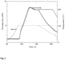
Fig. 2 shows the graph of the processing conditions SPS (pressing force and temperature as a function of time) for: (i)- PET-PET samples (A-C, Table 1) and three-layer composite samples I-VIII (Table 2); (ii)- for PET samples with three (sample VIII, Table 2) or ten (sample IX, Table 2) layers (PET foils). All samples are discs/cylinders with a diameter of 20 mm. The dwell time at the maximum SPS processing temperature is shorter for samples with 2 or 3 layers compared to the time for 10 layers; -
Fig. 3 shows the X-ray photoemission spectra (XPS) measured on the PET samples shown in Table 1: (a) - the whole spectrum; (b) - detail for carbon (C1s); (c) - detail for oxygen (O1s). The samples denomination are as in Table 1. -
Fig. 4 shows the X-ray diffraction spectra measured on PET foils before and after SPS (samples A and B, Table 1). -
Fig. 5 shows examples of layered composites (discs 20 mm in diameter) obtained by SPS: overview and cross-section. The notations of the samples correspond to those in Table 2. -
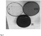
Fig. 6 shows the unreinforced multilayer PET samples obtained by SPS. Sample notations are as in Table 2. - The present invention will be described in detail below.
- In a first aspect, the invention provides a process for obtaining a layered composite material comprising placing at least one first layer and a second layer, one on top of the other, wherein the first layer is a plastic material and the second layer is a reinforcing element and processing thereof by applying intense electric field assisted sintering technique (SPS) in a mold to obtain a layered composite material.
- The process according to the invention discloses, in a preferred embodiment, layered composite materials wherein the layer with the reinforcing element overlaps totally or partially over the layer of the plastic material. Thus, one can imagine composite materials that can have, in the same layer of reinforcing element, one or more different reinforcing elements (materials), with the same or different properties. In a particularly preferred embodiment, the plastic material is in the foil form.
- In a particularly preferred embodiment, the process for obtaining a layered composite material comprises placing between 2 layers of plastic material, preferably in the foil form, of at least one reinforcing element and processing thereof by applying sintering technique assisted by an intense electric field (SPS), within a mold, to obtain a layered composite material.
- In a specific embodiment, the process for obtaining a layered composite material comprises placing the following layers in the following order:
- a first layer of plastic material
- a second layer comprising a reinforcing element
- a third layer of plastic material
- a fourth layer comprising a reinforcing element
- a fifth layer of plastic material.
- In another specific embodiment, the process for obtaining a layered composite material comprising placing the following layers in the following order:
- a first layer of plastic material
- a second layer comprising a reinforcing element
- a third layer comprising a reinforcing element
- a fourth layer of plastic material.
- The layered composite material according to the present invention can have the layer with the reinforcing element completely or partially superimposed on the layer of plastic material.
- The number of layers of plastic material and the number of layers of reinforcing elements can be varied depending on the purpose for which the composite material is designed. Also, in a layered composite material obtained by the process of the invention, the layers of plastic material and the layers of reinforcing elements can be the same or different and are chosen depending on the purpose for which the material is designed.
- In a particularly preferred embodiment, the plastic material is preferably in the foil form. In a preferred embodiment, the foils is from waste such as preferably, but not limited to, packaging. The process according to the present invention can use plastic foils selected from PET, ABS, PVC, PE, Nylon, PA, PP, PC, PS, etc., preferably PET. In an even more preferred embodiment, the plastic is from plastic containers used for bottled water. In a particularly preferred embodiment, the layer of plastic material, preferably in the form of plastic foil, has a maximum thickness of 1 mm, preferably 0.1-0.4 mm.
- In one embodiment, the reinforcing elements are selected from organic or inorganic materials in the form of foil, fibers or powders with different physico-chemical properties.
- In a particularly preferred embodiment, the reinforcing elements are selected from:
- inorganic materials with electrically or thermally conductive/insulating properties selected from the following categories: metals or alloys preferably selected from, but not limited to, Cu, Au, Ti, Al, alloys thereof (steels, Al alloys, Ni, Mg, Ti, etc), ceramic materials preferably selected from, but not limited to, Al2O3, B4C, BN, SiC, SiO2/glass, MgB2, etc., carbonaceous materials preferably selected from, but not limited to, carbon fibers , graphene, and
- organic materials with electrically or thermally conductive/insulating properties preferably selected from, but not limited to, wooden materials such as wood fibers, bamboo, cotton, linen, cane.
- In a particularly preferred embodiment, the reinforcing element can be a metal foil, electrically and thermally conductive, selected from Cu, Au, Ti, Al or alloys thereof with a thickness in the range of 5-20 µm, preferably 11 µm (see Table 2). In the case of layered composite materials wherein the reinforcing layer is metallic, the composite will be a good electrical conductor in certain areas or on the entire surface of the layer and can be used in applications where such a material is needed (e.g. PET-Cu- PET wherein the metal foil can be cut in the form of coils, for electromagnetic applications, electrical fuses, switches, resistive heating elements in the electrotechnical, automotive, household appliance, sensor industry, Table 3, No. 1).
- In another preferred embodiment, the composite can have 2 different metal reinforcement layers and thus will have 2 conductive channels each with certain electrical parameters (e.g. PET-Al-Cu-PET for electromagnetic applications, electrical fuses, switches, resistive heating elements in the electrotechnical, automotive, household appliances, sensors industry, Table 3, No. 10).
- In another preferred embodiment, the composite can have 2 different reinforcement layers, one with electrical conduction and the other with thermal conduction (PET-Cu-C-PET foil for resistive heating elements, Table; 3, No. 11).
- One can imagine many such composites with special properties depending on the target applications (Table 3). In other cases, the property of the composite will be defined by the property of one of the reinforcing elements or by the areas where the reinforcing elements are located (in case the overlap of the layers is partial). These composites combine several properties and become multifunctional. On the other hand, the plastic material on the outside of the layered composite material is chemically stable and therefore useful as anti-corrosion protection for the metal.
- In a preferred embodiment, the reinforcing element is in powder form. The thickness of the powder layer is in the range from 1 to 50 µm, preferably the thickness of the powder layer is 40 µm. Different powders can be used depending on the requirements of the material, MgB2 powders being particularly preferred so that the composite layered material has diamagnetic properties in the superconducting state (Table 3, No. 4), Al2O3, B4C, BN, Si, SiC, SiO2/glass for dielectric properties (Table 3, No. 3) and/or mechanical resistance (Table 3, No. 7) and/or anticorrosive, or SiO2/glass for optical properties (for example the composite is translucent, Table 3, No. 6).
- In a preferred embodiment, the reinforcing element is a carbonaceous material selected preferably from, but not limited to, carbon fibers or graphene (powder). In a preferred embodiment, the reinforcing element is a carbon fiber with a thickness chosen in the range of 0.05-0.7 mm, in particular with a thickness of 0.4 mm. The composite made has thermal conduction properties due to the carbon fibers and can be used in applications dedicated to this purpose. (e.g. PET - Carbon fiber - PET for resistive heating elements in the electrotechnical, household appliance, automotive industry, Table 3, No. 2)
- In a preferred embodiment, the reinforcing element is an organic wooden material selected from, but not limited to, wood fibers, bamboo, cotton, linen, cane. In a preferred embodiment, the reinforcing element is a wood fiber with a thickness chosen in the range of 0.05-0.1 mm, in particular with a thickness of 0.08 mm. The composite produced has thermal, electrical and anti-corrosion insulating properties. Wood fibers also change the mechanical properties in the sense of increasing the mechanical resistance (eg PET-organic-PET for thermal and electrical insulation elements in the electrotechnical, energy, construction, furniture, packaging industry, Table 3, No. 12).
- In a particularly preferred embodiment, the reinforcing element is selected from inorganic materials with superconducting properties such as: metals or alloys selected preferably from, but not limited to, Nb, Nb3Sn, NbTi, etc. and ceramic materials selected preferably from, but not limited to, MgB2, YBa2Cu3O7, Bi2Sr2CaCu2OX, Bi2Sr2Ca2Cu3O10, preferably in the form of foil, powders or fibers (known in specialized literature as whiskers or monocrystalline whiskers). In a preferred embodiment, the reinforcing element is in powder form. The thickness of the powder layer is in the range from 0.1 to 50 µm, preferably the thickness of the powder layer is 40 µm. The composite produced has diamagnetic properties in a superconducting state and electrical conduction (PET-superconductor-PET, current limiters, magnetic shields/filters/separators, magnetic sensors for the power industry, transports, energy, medical, space, Table 3, No. 4).
- In another particularly preferred embodiment, the reinforcing element is selected from inorganic materials with magnetic/non-magnetic properties such as metals/alloys selected preferably from, but not limited to, materials based on Fe, Ni, Co, RE (wherein RE are rare earths), Al, Au, Ag, Cu and ceramic materials selected preferably from, but not limited to, NdFeB, BiMn, REFeO3 preferably in foil or powder form. The preferred composites, made with powders (in layers with thicknesses of 1-50 µm, preferably 40 µm), especially with Al are non-magnetic and those with Fe, BiMn or NdFeB are ferromagnetic (the former is soft-magnetic and the others two are hard-magnetic). Permanent magnets, sensors, magnetic components for the automotive, electrotechnical, mechanical, processing industry can be obtained (Table 3, No. 5).
- In another preferred embodiment of the invention, the reinforcing element is selected from inorganic materials with optical properties such as ceramic materials preferably selected from SeTe, GeTe, ZnS, Ce doped with rare metals RE in powder form (with a layer thickness of 1-50 µm in diameter and particle size of 0.2-1 µm). The preferred composites, made with powders (in layers with thicknesses of 1-50 µm, preferably 40 µm) have optical properties, preferably in the visible or infrared spectrum or have upper or lower optical conversion properties (optical converters, luminescent radiation filters, mirrors, light radiation attenuators, components in solar cells for the automotive, energy, optical, optoelectronic industries, Table 3, No. 6)
- In another embodiment of the invention, the reinforcing element is selected from:
- inorganic materials with mechanical properties: selected preferably from metals/alloys, but not limited to Cu, Au, Ti, Al, alloys thereof, ceramic materials selected preferably, but not limited to, carbides, borides , nitrides, oxides: B4C, SiC, TiB2, MgB2, BN, Al2O3, SiO2/glass, carbonaceous materials selected preferably, but not limited to, carbon fibers, graphene and
- organic materials with mechanical properties selected from wooden materials, preferably, but not limited to, wood fibers, bamboo, cotton, linen, cane.
- The presence of metal foils in the composite (preferably with a thickness of 0.1-0.4 mm), powders (layers of 1-50 µm) or fibers (individual bulk fibers or fabrics with a layer thickness of up to 0.4 mm) provides mechanical resistance (Table 3, No. 7).
- In another embodiment of the invention, the reinforcing element is selected from:
- inorganic materials with biological properties (inert or active): metals preferably selected from, but not limited to, Ag, Cu, ceramic materials preferably selected from MgB2, Ca5(PO4)3(OH), CaO, CaCO3, NaCl, MgO, SiO2, Al2O3, ZrO2, Si/glass and
- organic materials with biological properties (inert or active) of the wooden type materials selected preferably from, but not limited to, wood fibers, bamboo, cotton, linen, cane. Preferred composites are with powder reinforcement, preferably Ag, Cu, or MgB2 (layers of 1-50 µm, preferably 40 µm) that induce bioactive properties such as antimicrobial or antitumor ones. MgB2 is biodegradable and biocompatible, being useful for obtaining the composites with controlled release of Mg and B. The powders for reinforcement, preferably Ca5(PO4)3(OH), CaO, CaCO3, NaCl and MgO can be biodegradable (when effects of, for example, bone or skin regeneration are targeted). Wooden or ceramic powders and fibers are biocompatible (and often bioinert) (Table 3, No. 8).
- In another preferred embodiment, the reinforcing element is selected from organic materials with acoustic properties of the wooden type materials selected preferably from, but not limited to, wood fibers, bamboo, cotton, linen, cane. These composites can be used in the manufacture of musical instruments or the construction of furniture and accessories for rooms with controlled sound (Table 3, No. 13).
- In another preferred embodiment, the reinforcing element is selected from organic or inorganic materials with different chemical stability/degradation properties (controlled degradation): metals/alloys type selected preferably, but not limited to those based on Zn, Mg, Fe, Ca, Na, Ti, etc., and organics of the wooden type materials selected preferably, but not limited to, wood fibers, bamboo, cotton, linen, cane (Table 3, No. 14) .
- Also, according to the process of the invention, can be obtained layered composite materials comprising a plurality of layers made of plastic material separated from each other by one or more reinforcing elements. In a preferred embodiment, the plastic material is in the form of plastic foil. In particular, the plastic foil comes from water containers.
- It should be noted that a multitude of reinforcing materials can be used depending on the purpose for which the layered composite material is designed. The present invention provides only a few examples which should not be considered limiting in any way. Through the process proposed in this application, composites with overlapping layers of electrical, magnetic, optical, etc. materials can be imagined and built, which can be used as devices and/or sensors (based on cumulative or synergistic physical/chemical effects).
- The position of the reinforcing element within the composite can be another advantage for functionality and/or integration and can be chosen depending on the desired application.
- The application of the sintering technique assisted by an intense electrical field (spark plasma sintering, SPS) on polymer powders (PA, PTFE, PLA) or on mixtures of polymer powders and metal powders (PI/carbon nanotubes, PI/diamond, PEDOT:PSS/Bi2S3, PEDOT:PSS/Bi2S3 nanotubes, PEDOT:PSS/CuSnSe3, PEDOT:PSS/Bi0.5Sb1.5Te3, PI/AIN, PI/AI, PI/Cu, PLA/graphene) produced massive sintered bodies [O. T. Adesina et al., The International Journal of Advanced Manufacturing Technology 116 759-775 (2021 )]. Sintering processes involve mass transfer by diffusion and viscous flow. In the case of the SPS, the specialized literature indicates the possibility of charge accumulations on the surface of two neighboring particles which, by discharging into the gas between them, can generate plasma and will contribute to mass transfer, especially through evaporation-condensation because of the very high temperatures of the plasma. Through this process, for example, it is considered possible to clean the surfaces of the involved components so that diffusion between particles becomes easy and, thus, sintering can be initiated/activated. From the above mentioned above results that the density of interfaces at contacts which depends on the particle size will influence the efficiency of sintering by the SPS. Large particle sizes or the use of solid bodies (e.g. foils or plates) to be bonded will require long or too long sintering times to be practically useful. A straightforward solution would be to increase the processing temperature or introduce some additions that facilitate the formation of a liquid phase for acceleration of the mass transfer processes. In the case of polymers, such a solution is not desirable for the reasons listed above.
- The present invention discloses the possibility of using the SPS technique to produce the direct (glue-free) 'bonding' of different materials (polymer-metals; polymer-paper, polymer-carbon fibers, polymer-textiles, etc.). Through this direct 'bonding' approach, layered composites with two or more layers are obtained. In the case of multilayer composites this approach allows the composite to be designed and manufactured with the desired layer sequence. For the plastic material, plastic foils can be used, preferably from packaging (PET from water containers), and for the reinforcing element, different materials were used as indicated above. The only step prior to the process is an alcohol cleaning of the plastic material, namely the recycled foils. The raw materials did not undergo any other kind of preparation/processing step, the process presented by the invention being advantageously carried out in a single step and in a short period of time (a few minutes), without melting and by activating the surface species that lead to direct bonding of the component layers into a composite massive body material.
- The process according to the invention is carried out by applying the SPS technique by placing at least one first layer and a second layer, one on top of the other, into the mold. The mold loaded with the sample is placed in the SPS furnace and aligned between the (vertical) pistons on which a uniaxial pressing force is applied. The process is characterized by the following steps:
- vacuum step: before the heating stage and after placing the mold with the sample in the SPS furnace, repeated vacuum (the pressure in the furnace varies between 10-60 Pa) - Ar-gas-cleaning (by introducing Ar up to a pressure of 0.8 - 0.9 atm) cycles are applied at room temperature. Two or three vacuum - Ar-gas-cleaning cycles are carried out. The working pressure of the vacuum in which are performed the next steps of processing is 10-60 Pa.
- the heating step takes place at a speed of 50 - 200°C/min, preferably 100°C, the uniaxial pressure on the sample during heating is in the range from 10 to 100 MPa, preferably at 16 MPa, the dwell time at maximum temperature (0.3 - 0.8 of the melting temperature of the plastic material from the composite) is between 1 - 10 minutes, preferably 2 minutes; it is performed using electric currents with a continuous component over which a pulsed component is superimposed consisting of groups composed of 12 pulses "on" and 2 pulses "off" with a total duration of 40 ms. Between pulses the pause is of 2 ms.
- the cooling step which is done exponentially, by stopping the power supply to the heat source and decreasing the uniaxial pressure on the sample so that at room temperature it reaches the value of 6 MPa in a time interval between 5 and 10 minutes, depending on the size of the sample. At room temperature, Ar is introduced up to atmospheric pressure, which allows opening the furnace.
- The process according to the invention discloses, in a preferred embodiment, layered composite materials wherein the layer with the reinforcing element overlaps totally or partially over the layer of plastic material.
- The process disclosed by the present invention eliminates existing technical difficulties in the field, achieving layered composite materials obtained by direct bonding, without adhesives or melting, in a single step, within a few minutes, with the formation of chemical bonds between the layers of the composite that provide the composite with different optical, electrical, magnetic, mechanical, degradation or biological properties. Another particularly important advantage resulting from application of this technique is that the layered composite material obtained can be designed from the beginning for a certain purpose and with certain characteristics and in certain areas.
- In another aspect, the invention provides a layered composite material obtained according to the process of the invention comprising plastic materials, preferably in the form of plastic foils, preferably from plastic waste, between which there can be at least one reinforcing element that can be selected from organic or inorganic materials. This layered composite material is obtained directly using the process disclosed by the invention. Composite materials have at least two layers and can be plastic-ceramic material (e.g. PET-Si), plastic-metal (e.g. PET-AI), plastic-organic material (PET-textile material). In another aspect, the invention provides a layered composite material comprising a plurality of layers formed of plastic material, preferably plastic foils, alternating the reinforcing layers as required in the applications (PET-BiMn-Cu-PET, Table 3, No . 15).
- In another aspect, the invention provides the use of the layered composite material, as obtained, in the electronics industry (preferably for moisture/electromagnetic protection of electronic circuits; connectors, coated/embedded conductors and insulators, devices and sensors), power and transport industries (preferably for thermal and/or electromagnetic protection/insulation of electric motors, protection against corrosion), packaging industry (for oxygen protection or storage of inert gases), biomedical applications with special functions (preferably antimicrobial, self-cleaning, antitumor), energy industry for manufacturing solar cells and batteries, in construction, aerospace, furniture and textiles.
- Table 3 shows some preferred embodiments of layered composite materials that can be obtained according to the invention, their uses and their field of use.
- Further, an specific embodiment is given which has an illustrative purpose and should not be considered as limiting the invention in any way.
- According to the invention, by using the process, layered composite materials formed from plastic material are obtained, preferably plastic foils from waste (preferably PET from packaging). Between the plastic material, preferably in the form of foil, the layered composite material has at least one reinforcing element (or intermediate layers) or can be in the form of foils (preferably Al, graphite), powders (preferably MgB2) or fibers (textiles, wood) from organic or inorganic materials (
Fig. 1 ). In a particularly preferred embodiment, the process comprises the following steps: - (1) cutting the plastic material in the form of foils, preferably PET, in the form of disks with a diameter of 20 mm and a thickness of 0.35 mm. Optionally, is cleaned with ethyl alcohol if necessary. The diameter of the foils was chosen to match the geometric specifications of the graphite die for SPS processing. The mold/punches used are cylindrical, but molds can be used in which the place where the foils are loaded can have various shapes (triangle, square, hexagon, etc.).
- (2) placing the plastic material, preferably in the form of foils, and the reinforcing elements (in the form of loosely dispersed or pre-compacted powder/fibers, foils, or layers of different materials) successively in the mold in the desired order where the overlap of the layers is total or partial;
- (3) sealing the mold thus loaded with foils with two graphite punches, while around the sample (the plastic foils, preferably PET, with the reinforcing element(s)) and the punches there is a separating graphite foil from the graphite mold which helps in easy extraction of the composite after SPS processing.
- (4) inserting the mold into a hydraulic press and pressing at 5 kN in a time interval between 10 and 60 seconds; After depressurization, the mold with the pressed sample is inserted into the SPS furnace and aligned with the pistons of the facility.
- (5) electric field assisted processing (SPS) using equipment manufactured by FCT Systeme GmbH (Germany). The massive sample is obtained following a heating-cooling cycle (
Fig. 2 ) as follows: the heating rate is 100 °C /min, the dwell time at 200 °C is 1 min. for 2 foils or 3 min. for more foils. Cooling is done exponentially by suddenly turning off the power supply. During heating, an increasing pressure from 6 MPa is applied to the sample, reaching a maximum value of 16 MPa (pressing force 5 kN inFig. 2 ), which is also maintained at the maximum processing temperature. Next, during cooling, the pressure is gradually reduced to 6 MPa, in 5 min. Processing is done under vacuum (between ~10 and ~60 Pa). The vacuum is obtained after placing the mold with the sample in the SPS furnace. Apply 2 or 3 vacuum cycles and introduce Ar gas up to 0.8-0.9 atm, thus cleaning the atmosphere in the SPS furnace. The temperature of the sample is monitored with the help of a thermocouple placed through a hole in the mold until close to the sample. The heating is carried out using intense electric currents (over 1300 A), which have a continuous component over which a pulsed component is superimposed, consisting of groups composed of 12 on pulses and 2 off pulses with a total duration of 40 ms. Between the pulses there is a pause of 2 ms. The intensity of the pulses in the groups is comparable to the intensity of the continuous component. At room temperature, the uniaxial pressure on the sample is brought to zero, Ar is introduced into the furnace until normal pressure is reached and the furnace is opened. - (6) Extraction of the processed sample from the graphite mold at room temperature is carried out with the help of a hydraulic press.
- In a particularly preferred embodiment, the plastic foils were taken from Dorna® (transparent/white) or Borsec® (transparent/blue) water containers.
- In this preferred embodiment, the SPS processing temperature was chosen to be below the melting temperature of the plastic material, namely the plastic foil, in particular the PET (-260 °C). Positive results leading to the bonding of the components of the layered composite material were obtained at a temperature in the range from 180 to 210 °C. The optimum SPS processing temperature of recycled PET composites is 200 °C. The overall X-ray photoemission spectra (XPS) and details for carbon (C1s) and oxygen (O1s) are shown in
Figs. 3 . The quantitative results estimated from the peak area are in Table 1. XPS was measured on a foil obtained acted from a container of water before SPS processing (sample A). Two foils are bonded by SPS and then mechanically exfoliated. The XPS spectrum was measured on the freshly exfoliated bonding surface (sample B). This sample was remeasured after 30 days of storage in air and in a desiccator prepared to absorb moisture (sample C). The comparative analysis between sample A and B highlights the change in carbon and oxygen spectra following SPS processing, which indicates the change in the surface state of PET. The XPS results for sample C show that air storage of the modified PET after SPS (sample B) produces a (partial) return to a surface state similar to that of the original sample A (Table 2,Fig. 3 b,c ). The change in spectra between the initial sample A and the SPS-processed sample B is similar to the change in spectra measured on PET before and after plasma processing from the reference document [E. Gonzalez et al., Langmuir 24 12636-12643 (2008 )], [ J. Wang et al., Surface & Coatings Technology 186 299-304 (2004 )], [L. Yang et al., Applied Surface Science 255 4446-4451 (2009 )], [ K. J. Pratt et al., Journal of Biomedical Materials Research 23 1131-1147 (1989 )], [N.L. Singh et al., Radiation Measurements 40 746 - 749 (2005 )], [ K. Uehara et al., Carbon-related Materials in Recognition of Nobel Lectures by Prof. Akira Suzuki in ICCE 391-418 (2017 )]. - As in the case of plasma treatments of the PET foil, under the action of SPS, radicals (polar groups) -COOH and -OH are produced (at. % of C are decreasing and at. % of O are increasing, Table 1). By recombining them and acording to the chemical reaction:
-COOH + -OH → -COO- + H2O
the chemical bonds that ensure the adhesion of the PET foils are made [K. Uehara et al., Carbon-related Materials in Recognition of Nobel Lectures by Prof. Akira Suzuki in ICCE 391-418 (2017 )], [T. S. Salem, PET Surface Properties affected by low temperature plasma modification (doczz.n et)], [F. Leroux et al., Journal of Adhesion Science and )]. - The X-ray diffraction from
Fig. 4 taken before (sample A) and after SPS (sample B) shows that no major structural changes occurred. The material is crystalline and the only differences are related to the degree of crystallinity that increases (diffraction lines narrow) as a result of heating PET to 200 °C during SPS processing. No amorphous phases are observed in the X-ray diffraction spectra, indicating no melting has occured. - Observation by optical microscopy (
Fig. 5 ) or scanning electron microscopy of the bonding areas confirms the lack of melting of the materials. This result is also supported by the fact that materials with PET foils without reinforcement maintain their transparency (sample I inFig. 5 ,6 ). Materials composed of more than three PET films (samples VIII and IX, Table 2,Fig. 5 ) gradually lose their transparency with increasing total thickness. From the above mentioned, the chosen SPS processing conditions produce effects similar to two-step bonding methods consisting of plasma irradiation of the surface and hot pressing [K. Uehara et al., Carbon-related Materials in Recognition of Nobel Lectures by Prof. Akira Suzuki in ICCE 391-418 (2017 )] and does not rely on mass transfer processes specific to sintering. - The layered composite materials obtained by the process disclosed by the present invention (using plastic material, preferably foils from PET packaging or other industrial plastics selected from, but not limited to, PET, ABS, PVC, PE, Nylon, PA, PP , PC, PS) can be designed as required and thus used in applications in the electronics industry (e.g. moisture/electromagnetic protection of electronic circuits; coated/embedded connectors, conductors and insulators, devices and sensors), power industry and transports (thermal and/or electromagnetic protection/isolation of electric motors, corrosion protection), advanced packaging industry for food preservation (by oxygen protection or inert gas storage), biomedical applications requiring special functions (e.g. antimicrobial, self-cleaning ), the energy industry in the manufacture of solar cells (considering that the transparency of the PET SPS-processed) and batteries, in construction, aerospace, furniture and textile industries. Several comparative studies were carried out to highlight the quality of the product obtained by applying the process described by the present invention.
Table 1 XPS results on samples of: PET (raw material from Borsec water containers) (sample A); PET after SPS and exfoliation (sample B); PET after SPS, exfoliation and storage in air for 30 days (sample C). Measurements B and C were performed on the bonding surface of a foil obtained by exfoliation from the material processed by SPS and composed of two PET foils. Material Sample C (1s) %at. O (1s) %at. PET (raw material) A 78.8 21.2 PET SPS (2 exfoliated foils immediately after SPS) B 73.0 27.0 PET SPS 30z (2 exfoliated foils stored in air for 30 days after SPS) C 80.3 19.7 Table 2 Layered composite materials with recycled PET foils matrix and with different reinforcements. The notations of the samples are as in Fig. 4 and 5. Composite material Sample No. No. Composite layers Matrix material details Reinforcement material details PET-PET I ( Fig. 4 ,5 )2 PET (polyethylene terephthalate ) transparent, recycled from Dorna
- PET-Textile (tiv)-PET II ( Fig. 4 )3 Textile tape - thickness ∼0.15 mm/ Stoklasa textilni galanterie s.r.o. PET-Napkin-PET III ( Fig. 4 )3 mineral water containers; foil of ∼0.35 µm thickness; melting temperature ∼260 °C wood fiber - cleaning wipes / thickness ∼0.08 mm/ Kimtech Kimwipes Science PET-Al foil-PET IV ( Fig. 4 )3 aluminum foil - thickness 11 µm / Delhaize Le Lion PET -C fiber-PET V ( Fig. 4 )3 carbon fiber - thickness 0.2 mm /Spania ClipCarbono PET -C foil - PET VI ( Fig. 4 )3 carbon foil - thickness 0.4 mm / FCT Systeme GmbH PET-MgB2 powder- PET VII ( Fig. 4 )3 MgB2 powder/ LTS Research Laboratories Inc / the thickness of the composite layer ∼40µm PET- PET - PET VIII ( Fig. 5 )3 PET (polyethylene terephthalate ) transparent/blue recycled from Borsec mineral water containers; - thickness 0.35 mm; melting temperature ∼260 °C
- PET-multilayer IX ( Fig. 5 )10 Table 3 Preferred layered composite materials that can be obtained according to the invention, their aplications and their industrial field of use. No. Composite Plastic material Reinforcement material and properties Applications Industry 1 Plastic-Metal; e.g. PET, PS, PVC, LDPE e.g. Cu, Au, Ti, Al, alloys; Electrical switches, electrical connectors, electrical fuses, resistive heating elements, magnetic shielding elements, etc. Transports (cars), Electrotechnics, Constructions, Household appliances Plastic-Metal-Plastic Properties: electrical conduction, thermal conduction 2 Plastic-inorganic material; e.g. PET, PS, PVC, LDPE e.g. C fiber Heat transfer elements Automotive, Construction, Electrical engineering Plastic-inorganic material-Plastic Properties: conduction/therm al insulation 3 Plastic-ceramic; e.g. PET, PS, PVC, LDPE e.g. Al2O3, ZrO2 Thermal and electrical insulation elements Energetics, Constructions, Electrotechnics Properties: Plastic-ceramic-Plastic thermal resistance and electrical resistivity (dielectrics) 4 Plastic - Supercond ucting material; e.g. PET, PS, PVC, LDPE e.g. Nb, V, Nb3Sn, NbTi, MgB2, YBa2Cu3O7, Bi2Sr2CaCu2O8, Bi2Sr2Ca2Cu3O10 Current limiters, magnetic shields/filters/se parators, magnetic sensors/wires and superconducting cables Power, Energy, Transport, Medical, Space, Mining Plastic-Superconducting material - Plastic Properties: superconductivity, diamagnetism 5 Plastic-magnetic; e.g. PET, PS, PVC, LDPE e.g. NdFeB, BiMn, REFeO3 Magnetic Permanent magnets, sensors, magnetic components, electromagnetic actuators Automotive, Electrical, Plastic-magnetic-Plastic properties 6 Plastic-optic; e.g. PET, PS, PVC, LDPE e.g. SeTe, GeTe, ZnS, Ce dopped with RE Optical converters, luminescent radiation filters, mirrors, light radiation attenuators, components in solar cells Automotive, Energy, Optics, Optoelectronics Plastic-optic-Plastic Properties: luminescence, photoluminescence, optical transparency, luminescent conversion 7 Plastic-metal/hard ceramic; e.g. PET, PS, PVC, LDPE e.g. Ti, W, B4C, SiC, TiB2 Mechanical shock protection Automotive, Construction, Space, Electrotechnics Properties: Plastic-metal/hard ceramic-Plastic mechanical resistance 8 Plastic-biomaterial e.g. PET, PS, PVC, LDPE e.g. Ag, Ti, MgB2, Ca5(PO4)3(OH), CaO, CaCO3, NaCl, MgO, SiO2, Al2O3, ZrO2 Antibacterial protection, sterile dressings, sterile packaging, prostheses/orth eses, medical instruments Medical Plastic-biomaterial -Plastic Properties: biocompatibility, bioinertia, bioresorbability, bioactivity 9 Plastic-Metal1-Plastic-Metal2-Plastic e.g. PET, PS, PVC, LDPE e.g. Cu, Al Electrical and thermal conduction properties Electric switches, resistive heating elements Automotive, Electrical engineering 10 Plastic-Metal1-Metal2-Plastic e.g. PET, PS, PVC, LDPE e.g. Cu, Al Electric switches, resistive heating elements Automotive, Electrical engineering Electrical and thermal conduction properties 11 Plastic-Metal-Inorganic-Plastic e.g. PET, PS, PVC, LDPE e.g. Cu, C-folie Electrical and thermal conductors Automotive, Electrical engineering Electrical and thermal conduction properties 12 Plastic-organic; e.g. PET, PS, PVC, LDPE e.g. wood fiber or paper napkin (cotton) Thermal and electrical insulators, anti-corrosion Automotive, Energy, Electrotechnics, Constructions, Furniture, Packaging Plastic-organic-plastic Electrical conduction (insulators) and thermal properties 13 Plastic-acustic; e.g. PET, PS, PVC, LDPE e.g. wood fibers Acoustic components for musical instruments, furniture and room accessories with controlled sound Furniture construction Musical instruments Plastic-acustic-plastic Acoustic properties 14 Plastic-reinforcem ent with controlled degradation e.g. PET, PS, PVC, LDPE e.g. Metals: Zn, Mg, Fe, Al, Cu and organic: wood fibers, bamboo, cotton, linen, cane Furniture, components, chemical protection, sensors Transports, Constructions, Furniture, Electrotechnics, Chemicals Corrosion properties or corrosion resistance 15 Plastic-magnetic -electric-Plastic e.g. PET, PS, PVC, LDPE e.g.: BiMn magnetic and Cu electric conductor Sensors, switches Electrotechnics - By applying the process disclosed by the present invention, layered composite materials are obtained which have the following advantages compared to the existing layered composite materials in the state of the art:
- Bonding between layers is done directly, without melting, with the formation of chemical bonds at the interface between two materials in a single processing step;
- The properties of the component materials of the composite do not change in volume after using the process of obtaining the composite by the proposed process.
- Because no adhesives are used, there are no problems related to toxicity and pollution;
- The raw materials were taken from waste such as plastic packaging, preferably in the form of foil; this is important because the impact of this waste on the environment is reduced.
- It is a simple process that does not require special preparation/processing of the raw materials.
- The layered composite material obtained by the process of the invention can be designed by assembling the layers in the desired order and placed into certain region(s) according to the requirments of the applications.
- The use of the process with the application of SPS forms chemical bonds between the component layers of the material, which leads to their increased mechanical resistance compared to similar composite materials obtained through conventional processes in which matrix breakage causes damage to the material and reinforcement does not contribute to maintaining the integrity and mechanical resistance: in the case of the materials obtained by the presented process, the layered composite material better retain its structural integrity and mechanical resistance due to the chemical bonds that are established between the matrix and the reinforcement.
Claims (15)
- A process for obtaining a layered composite material comprising the placing at least one first layer and a second layer, one on top of the other, wherein- the first layer is a plastic material and- the second layer is a reinforcing elementand processing thereof by applying intense electric field sintering technique (SPS) in a mold to obtain a layered composite material.
- The process for obtaining a layered composite material according to claim 1 wherein the layer with the reinforcing element overlaps totally or partially over the layer of plastic material.
- The process according to any of the preceding claims wherein the plastic material is selected from polyethylene terephthalate (PET), polyethylene (PE), polyvinyl chloride (PVC), polypropylene (PP), polystyrene (PS), acrylonitrile butadiene styrene (ABS) , polyamide (PA or nylon), polycarbonate (PC), preferably in foil form.
- The process according to any of the preceding claims wherein the reinforcing element is selected from organic or inorganic materials with different physico-chemical properties.
- The process according to claim 4 wherein the reinforcing element is selected from inorganic materials with electrically or thermally conductive/insulating properties such as: metals or alloys preferably selected from Cu, Au, Ti, Al, alloys thereof (steels, Al alloys, Ti, Ni, etc.), ceramic materials preferably selected from Al2O3, B4C, BN, SiC, SiO2/glass, MgB2, etc., carbonaceous materials preferably selected from carbon fibers, graphene, and organic materials with electrical or thermal conductive/insulating properties preferably selected from wooden materials such as wood fibers, bamboo, cotton, linen, cane.
- The process according to claim 4 wherein the reinforcing element is selected from inorganic materials with superconducting properties such as: metals or alloys preferably selected from Nb, V, La, Nb3Sn, NbTi, etc. and ceramic materials preferably selected from MgB2, YBa2Cu3O7, Bi2Sr2CaCu2O8, Bi2Sr2Ca2Cu3O10.
- The process according to claim 4 wherein the reinforcing element is selected from inorganic materials with magnetic/non-magnetic properties such as metals/alloys preferably selected from Fe, Ni, Co, steel, rare earths (RE), Al, Au, Ag, Cu and ceramic materials preferably selected from NdFeB, BiMn, REFeO3.
- The process according to claim 4 wherein the reinforcing element is selected from inorganic materials with optical properties such as ceramic materials preferably selected from SeTe, GeTe, ZnS, Ce doped with rare earths (RE).
- The process according to claim 4 wherein the reinforcing element is selected from inorganic materials with mechanical properties such as metals/alloys preferably selected from Cu, Au, Ti, Al, or alloys thereof, ceramic materials preferably selected from carbides, borides, nitrides , oxides (preferably B4C, SiC, TiB2, MgB2, BN, Al2O3, SiO2/glass), carbonaceous materials preferably selected from carbon fibers, graphene, and organic materials with mechanical properties such as wooden materials preferably selected from wood fibers, bamboo, cotton, linen, cane.
- The process according to claim 4 wherein the reinforcing element is selected from inorganic materials with biological properties (inert or active): metals preferably selected from Ag, Cu, ceramic materials preferably selected from MgB2, Ca5(PO4)3(OH), CaO, CaCO3, NaCl, MgO, SiO2, Al2O3, ZrO2, Si/glass and organic materials with biological properties such as wooden materials preferably selected from wood fibers, bamboo, cotton, linen, cane.
- The process according to claim 4 wherein the reinforcing element is selected from organic materials with acoustic properties such as wooden materials preferably selected from wood fibers, bamboo, cotton, linen, cane.
- The process according to claim 4 wherein the reinforcing element is selected from inorganic materials with stability/degradation (controlled degradation) chemical properties (inert or active): metals/alloys preferably selected from Zn, Mg, Fe, Ca, Na, etc., and organic materials with chemical properties (inert or active) such as wooden materials preferably selected from wood fibers, bamboo, cotton, linen, cane.
- The process according to claim 1 wherein the processing by applying intense electric field assisted sintering technique (SPS) is carried out by placing in the mold at least one first layer and a second layer, one on top of the other, and is characterized by the following steps:- vacuum step: applying at least 2 cycles of vacuum (the pressure in the furnace varies between 10-60 Pa) - Ar-gas-cleaning (pressure of 0.8 - 0.9 atm);- heating step takes place at a speed of 50 - 200°C/min, preferably 100°C, the uniaxial pressure on the sample during heating is in the range from 10 to 100 MPa, preferably at 16 MPa, the dwell time at maximum temperature (0.3 - 0.8 of the melting temperature of the plastic material of the composite) is between 1 - 10 minutes, preferably 2 minutes; it is performed using electric currents with a continuous component over which a pulsed component is superimposed consisting of groups composed of 12 pulses "on" and 2 pulses "off" with a total duration of 40 ms with a 2ms pause between them;- cooling step which is done exponentially, by stopping the power supply to the heat source and decreasing the uniaxial pressure on the sample so that at room temperature it reaches the value of 6 MPa in a time interval between 5 and 10 minutes, depending on the size of the sample.
- Layered composite material obtained according to any one of claims from 1 to 13.
- Use of the layered composite material obtained according to any one of claims from 1 to 14 in the electronics industry (preferably for moisture/electromagnetic protection of electronic circuits; connectors, coated/embedded conductors and insulators, devices and sensors), power and transport industries (preferably for thermal and/or electromagnetic and/or acoustic protection/insulation of electric motors, corrosion protection), packaging industry (for oxygen protection or storage of inert gases), biomedical applications with special functions (preferably inert, antimicrobial, self-cleaning, biodegradable, antitumor), the energy industry for the manufacture of solar cells and batteries, in construction, the aerospace industry, the furniture industry and textiles.
Applications Claiming Priority (1)
| Application Number | Priority Date | Filing Date | Title |
|---|---|---|---|
| ROA202200516A RO137235A0 (en) | 2022-08-25 | 2022-08-25 | Composite laminates based on plastic foils recycled from packaging |
Publications (1)
| Publication Number | Publication Date |
|---|---|
| EP4328012A1 true EP4328012A1 (en) | 2024-02-28 |
Family
ID=85035462
Family Applications (1)
| Application Number | Title | Priority Date | Filing Date |
|---|---|---|---|
| EP23162517.9A Pending EP4328012A1 (en) | 2022-08-25 | 2023-03-17 | Process for obtaining a layered composite material, layered composite material and its uses |
Country Status (2)
| Country | Link |
|---|---|
| EP (1) | EP4328012A1 (en) |
| RO (1) | RO137235A0 (en) |
Cited By (1)
| Publication number | Priority date | Publication date | Assignee | Title |
|---|---|---|---|---|
| CN120817822A (en) * | 2025-09-17 | 2025-10-21 | 内蒙古京航特碳科技股份有限公司 | A Fe/Al layered composite material based on continuous carbon fiber and its preparation method |
Citations (1)
| Publication number | Priority date | Publication date | Assignee | Title |
|---|---|---|---|---|
| JPH09131828A (en) * | 1995-11-09 | 1997-05-20 | Kanegafuchi Chem Ind Co Ltd | Functionally graded material and manufacturing method thereof |
-
2022
- 2022-08-25 RO ROA202200516A patent/RO137235A0/en unknown
-
2023
- 2023-03-17 EP EP23162517.9A patent/EP4328012A1/en active Pending
Patent Citations (1)
| Publication number | Priority date | Publication date | Assignee | Title |
|---|---|---|---|---|
| JPH09131828A (en) * | 1995-11-09 | 1997-05-20 | Kanegafuchi Chem Ind Co Ltd | Functionally graded material and manufacturing method thereof |
Non-Patent Citations (17)
| Title |
|---|
| A. KELLYC. ZWEBEN: "Comprehensive Composite Materials", 2000, PERGAMON PRESS, ELSEVIER SCIENCE |
| A. KONDYURINM. BILEK: "Ion Beam Treatment of Polymers: Application Aspects from Medicine to Space", 2010, ELSEVIER |
| ADESINA OLUWAGBENGA TOBI ET AL: "Spark plasma sintering of polymer and polymer-based composites: a review", THE INTERNATIONAL JOURNAL OF ADVANCED MANUFACTURING TECHNOLOGY, SPRINGER, LONDON, vol. 116, no. 3-4, 29 May 2021 (2021-05-29), pages 759 - 775, XP037529832, ISSN: 0268-3768, [retrieved on 20210529], DOI: 10.1007/S00170-021-07349-Z * |
| E. GONZALEZ ET AL., LANGMUIR, vol. 24, 2008, pages 12636 - 12643 |
| E. M. LISTON ET AL., JOURNAL OF ADHESION SCIENCE AND TECHNOLOGY, vol. 7, 1993, pages 1091 - 1127 |
| F. LEROUX ET AL., JOURNAL OF ADHESION SCIENCE AND TECHNOLOGY, vol. 20, 2006, pages 939 - 957 |
| J. M. GRACEL.J. GERENSER: "Plasma treatment of polymers", JOURNAL OF DISPERSION SCIENCE AND TECHNOLOGY, vol. 24, 2003, pages 305 - 341 |
| J. WANG ET AL., SURFACE & COATINGS TECHNOLOGY, vol. 186, 2004, pages 299 - 304 |
| K. J. PRATT ET AL., JOURNAL OF BIOMEDICAL MATERIALS RESEARCH, vol. 23, 1989, pages 1131 - 1147 |
| K. UEHARA ET AL., CARBON-RELATED MATERIALS IN RECOGNITION OF NOBEL LECTURES BY PROF. AKIRA SUZUKI IN ICCE, 2017, pages 391 - 418 |
| L. YANG ET AL., APPLIED SURFACE SCIENCE, vol. 255, 2009, pages 4446 - 4451 |
| M. GONDA ET AL., INTERNATIONAL JOURNAL OF ADHESION AND ADHESIVES, vol. 100, 2020, pages 102604 |
| M. KUTZ: "Mechanical engineers' handbook", 2006, JOHN WILEY & SONS, article "Materials and Mechanical Design" |
| N.L. SINGH ET AL., RADIATION MEASUREMENTS, vol. 40, 2005, pages 746 - 749 |
| O. T. ADESINA ET AL., THE INTERNATIONAL JOURNAL OF ADVANCED MANUFACTURING TECHNOLOGY, vol. 116, 2021, pages 759 - 775 |
| P. FABBRIM. MESSORI, MODIFICATION OF POLYMER PROPERTIES, 2017, pages 109 - 130 |
| T. S. SALEM, PET SURFACE PROPERTIES AFFECTED BY LOW TEMPERATURE PLASMA MODIFICATION (DOCZZ.NET) |
Cited By (1)
| Publication number | Priority date | Publication date | Assignee | Title |
|---|---|---|---|---|
| CN120817822A (en) * | 2025-09-17 | 2025-10-21 | 内蒙古京航特碳科技股份有限公司 | A Fe/Al layered composite material based on continuous carbon fiber and its preparation method |
Also Published As
| Publication number | Publication date |
|---|---|
| RO137235A0 (en) | 2023-01-30 |
Similar Documents
| Publication | Publication Date | Title |
|---|---|---|
| Shen et al. | Microstructural prototyping of ceramics by kinetic engineering: applications of spark plasma sintering | |
| KR100241677B1 (en) | Manufacturing method of high strength metal powder processed product coated with thermoplastic material | |
| EP4328012A1 (en) | Process for obtaining a layered composite material, layered composite material and its uses | |
| US8615867B2 (en) | Superconductive element and relative preparation process | |
| Khalil | Advanced sintering of nano-ceramic materials | |
| WO2003014415A1 (en) | Composite material made from a substrate material and a barrier layer material | |
| KR101710203B1 (en) | Alumina sintered body, method for manufacturing the same, and semiconductor manufacturing apparatus member | |
| KR102047435B1 (en) | Metal Matrix Composite Heat Spreader with High Thermal Conduction Efficiency | |
| Zhang et al. | Field activated sintering techniques: a comparison and contrast | |
| Ferraris et al. | Silver nanocluster/silica composite coatings obtained by sputtering for antibacterial applications | |
| Homola et al. | Large‐area open air plasma sources for roll‐to‐roll manufacture: High‐power density surface plasma generated by diffuse coplanar surface barrier discharge | |
| WO2019002695A1 (en) | CERAMIC COMPOSITE MATERIAL | |
| Joseph et al. | Low temperature sintering lead‐free dielectric x BiScO3‐(1‐x) BaTiO3 for energy storage applications | |
| IL282127B2 (en) | Method for manufacturing a conductive composite comprising at least one surface layer comprising few-layer graphene | |
| Nagai et al. | Fabrication and evaluation of porous Al2O3 AgI composites | |
| JPH01317157A (en) | Functional ceramic article and production thereof | |
| Liu et al. | New microwave dielectric ceramics with near-zero τ f in the Ba (Mg 1/3 Nb 2/3) O 3-Ba (Ni 1/3 Nb 2/3) O 3 system. | |
| EP0437625B1 (en) | Method of producing metallic complex and metallic complex produced thereby | |
| CN100431068C (en) | Ceramic laminate and manufacturing method thereof | |
| Rice et al. | Wrappable ceramic insulation for superconducting magnets | |
| Öktem et al. | Investigating the applicability of metal ion implantation technique (MEVVA) to textile surfaces | |
| Klimov et al. | Electron beam sintering of Mn-Zn ferrites using a forevacuum plasma electron source | |
| Selvam et al. | Fundamentals of nanoceramics and their composites | |
| Inoue et al. | Review of ion engineering center and related projects in ion engineering research institute | |
| US20230382807A1 (en) | Method for sintering ceramic materials |
Legal Events
| Date | Code | Title | Description |
|---|---|---|---|
| PUAI | Public reference made under article 153(3) epc to a published international application that has entered the european phase |
Free format text: ORIGINAL CODE: 0009012 |
|
| STAA | Information on the status of an ep patent application or granted ep patent |
Free format text: STATUS: THE APPLICATION HAS BEEN PUBLISHED |
|
| AK | Designated contracting states |
Kind code of ref document: A1 Designated state(s): AL AT BE BG CH CY CZ DE DK EE ES FI FR GB GR HR HU IE IS IT LI LT LU LV MC ME MK MT NL NO PL PT RO RS SE SI SK SM TR |
|
| STAA | Information on the status of an ep patent application or granted ep patent |
Free format text: STATUS: REQUEST FOR EXAMINATION WAS MADE |
|
| 17P | Request for examination filed |
Effective date: 20240814 |
|
| RBV | Designated contracting states (corrected) |
Designated state(s): AL AT BE BG CH CY CZ DE DK EE ES FI FR GB GR HR HU IE IS IT LI LT LU LV MC ME MK MT NL NO PL PT RO RS SE SI SK SM TR |
|
| STAA | Information on the status of an ep patent application or granted ep patent |
Free format text: STATUS: EXAMINATION IS IN PROGRESS |
|
| 17Q | First examination report despatched |
Effective date: 20250404 |