EP4327930A1 - Multistufenreaktor zum durchführen exothermer gleichgewichtsreaktionen - Google Patents
Multistufenreaktor zum durchführen exothermer gleichgewichtsreaktionen Download PDFInfo
- Publication number
- EP4327930A1 EP4327930A1 EP22192298.2A EP22192298A EP4327930A1 EP 4327930 A1 EP4327930 A1 EP 4327930A1 EP 22192298 A EP22192298 A EP 22192298A EP 4327930 A1 EP4327930 A1 EP 4327930A1
- Authority
- EP
- European Patent Office
- Prior art keywords
- reactor
- gas mixture
- reaction
- heat exchanger
- cell
- Prior art date
- Legal status (The legal status is an assumption and is not a legal conclusion. Google has not performed a legal analysis and makes no representation as to the accuracy of the status listed.)
- Pending
Links
- 238000006243 chemical reaction Methods 0.000 title claims abstract description 157
- 238000001816 cooling Methods 0.000 claims abstract description 118
- OKKJLVBELUTLKV-UHFFFAOYSA-N Methanol Chemical compound OC OKKJLVBELUTLKV-UHFFFAOYSA-N 0.000 claims abstract description 102
- 238000005191 phase separation Methods 0.000 claims abstract description 62
- 238000009833 condensation Methods 0.000 claims abstract description 51
- 230000005494 condensation Effects 0.000 claims abstract description 51
- 239000007795 chemical reaction product Substances 0.000 claims abstract description 44
- 230000015572 biosynthetic process Effects 0.000 claims abstract description 39
- 238000003786 synthesis reaction Methods 0.000 claims abstract description 36
- 239000012530 fluid Substances 0.000 claims abstract description 10
- 238000004891 communication Methods 0.000 claims abstract description 9
- 239000007789 gas Substances 0.000 claims description 305
- 239000000203 mixture Substances 0.000 claims description 222
- 239000000047 product Substances 0.000 claims description 61
- 239000007788 liquid Substances 0.000 claims description 39
- 238000000926 separation method Methods 0.000 claims description 39
- 239000011949 solid catalyst Substances 0.000 claims description 27
- 239000002826 coolant Substances 0.000 claims description 26
- 239000003054 catalyst Substances 0.000 claims description 24
- CURLTUGMZLYLDI-UHFFFAOYSA-N Carbon dioxide Chemical compound O=C=O CURLTUGMZLYLDI-UHFFFAOYSA-N 0.000 claims description 20
- 229910052739 hydrogen Inorganic materials 0.000 claims description 13
- 239000001257 hydrogen Substances 0.000 claims description 13
- 229910002091 carbon monoxide Inorganic materials 0.000 claims description 11
- 238000007599 discharging Methods 0.000 claims description 11
- 239000001569 carbon dioxide Substances 0.000 claims description 10
- 229910002092 carbon dioxide Inorganic materials 0.000 claims description 10
- UGFAIRIUMAVXCW-UHFFFAOYSA-N Carbon monoxide Chemical class [O+]#[C-] UGFAIRIUMAVXCW-UHFFFAOYSA-N 0.000 claims description 9
- 239000011159 matrix material Substances 0.000 claims description 7
- 239000007791 liquid phase Substances 0.000 claims description 6
- 238000004519 manufacturing process Methods 0.000 claims description 6
- 239000007792 gaseous phase Substances 0.000 claims description 5
- 230000005484 gravity Effects 0.000 claims description 5
- 229910002090 carbon oxide Inorganic materials 0.000 claims description 2
- 230000001404 mediated effect Effects 0.000 claims description 2
- 125000004435 hydrogen atom Chemical class [H]* 0.000 claims 1
- 239000000463 material Substances 0.000 abstract description 4
- 238000010276 construction Methods 0.000 abstract 1
- XLYOFNOQVPJJNP-UHFFFAOYSA-N water Substances O XLYOFNOQVPJJNP-UHFFFAOYSA-N 0.000 description 35
- 239000006227 byproduct Substances 0.000 description 14
- 239000000498 cooling water Substances 0.000 description 14
- 238000009835 boiling Methods 0.000 description 11
- 238000000034 method Methods 0.000 description 10
- UFHFLCQGNIYNRP-UHFFFAOYSA-N Hydrogen Chemical compound [H][H] UFHFLCQGNIYNRP-UHFFFAOYSA-N 0.000 description 9
- IJGRMHOSHXDMSA-UHFFFAOYSA-N Atomic nitrogen Chemical compound N#N IJGRMHOSHXDMSA-UHFFFAOYSA-N 0.000 description 8
- VNWKTOKETHGBQD-UHFFFAOYSA-N methane Chemical compound C VNWKTOKETHGBQD-UHFFFAOYSA-N 0.000 description 8
- 238000010438 heat treatment Methods 0.000 description 6
- 229920006395 saturated elastomer Polymers 0.000 description 6
- 238000013461 design Methods 0.000 description 5
- 238000011144 upstream manufacturing Methods 0.000 description 5
- 229910052757 nitrogen Inorganic materials 0.000 description 4
- 239000012071 phase Substances 0.000 description 4
- 238000009826 distribution Methods 0.000 description 3
- 150000002431 hydrogen Chemical class 0.000 description 3
- 238000010926 purge Methods 0.000 description 3
- 230000008646 thermal stress Effects 0.000 description 3
- 238000012546 transfer Methods 0.000 description 3
- RYGMFSIKBFXOCR-UHFFFAOYSA-N Copper Chemical compound [Cu] RYGMFSIKBFXOCR-UHFFFAOYSA-N 0.000 description 2
- 238000009825 accumulation Methods 0.000 description 2
- 150000001298 alcohols Chemical class 0.000 description 2
- 229910052799 carbon Inorganic materials 0.000 description 2
- 229910052802 copper Inorganic materials 0.000 description 2
- 239000010949 copper Substances 0.000 description 2
- 150000002148 esters Chemical class 0.000 description 2
- 150000002170 ethers Chemical class 0.000 description 2
- 238000009434 installation Methods 0.000 description 2
- 238000009413 insulation Methods 0.000 description 2
- 150000002576 ketones Chemical class 0.000 description 2
- 238000012545 processing Methods 0.000 description 2
- 239000011541 reaction mixture Substances 0.000 description 2
- 238000011084 recovery Methods 0.000 description 2
- 230000035882 stress Effects 0.000 description 2
- OKTJSMMVPCPJKN-UHFFFAOYSA-N Carbon Chemical compound [C] OKTJSMMVPCPJKN-UHFFFAOYSA-N 0.000 description 1
- 229910000831 Steel Inorganic materials 0.000 description 1
- 230000001419 dependent effect Effects 0.000 description 1
- 230000008021 deposition Effects 0.000 description 1
- 230000005611 electricity Effects 0.000 description 1
- 238000005868 electrolysis reaction Methods 0.000 description 1
- 239000002737 fuel gas Substances 0.000 description 1
- 239000012535 impurity Substances 0.000 description 1
- 239000004615 ingredient Substances 0.000 description 1
- 230000010354 integration Effects 0.000 description 1
- 239000012263 liquid product Substances 0.000 description 1
- 229910052751 metal Inorganic materials 0.000 description 1
- 239000002184 metal Substances 0.000 description 1
- 238000002156 mixing Methods 0.000 description 1
- 239000002245 particle Substances 0.000 description 1
- 239000008188 pellet Substances 0.000 description 1
- 238000004886 process control Methods 0.000 description 1
- 239000012429 reaction media Substances 0.000 description 1
- 239000007787 solid Substances 0.000 description 1
- 238000001179 sorption measurement Methods 0.000 description 1
- 239000010959 steel Substances 0.000 description 1
- 239000000725 suspension Substances 0.000 description 1
- 239000002918 waste heat Substances 0.000 description 1
- 238000010626 work up procedure Methods 0.000 description 1
Images

Classifications
-
- B—PERFORMING OPERATIONS; TRANSPORTING
- B01—PHYSICAL OR CHEMICAL PROCESSES OR APPARATUS IN GENERAL
- B01J—CHEMICAL OR PHYSICAL PROCESSES, e.g. CATALYSIS OR COLLOID CHEMISTRY; THEIR RELEVANT APPARATUS
- B01J8/00—Chemical or physical processes in general, conducted in the presence of fluids and solid particles; Apparatus for such processes
- B01J8/02—Chemical or physical processes in general, conducted in the presence of fluids and solid particles; Apparatus for such processes with stationary particles, e.g. in fixed beds
- B01J8/04—Chemical or physical processes in general, conducted in the presence of fluids and solid particles; Apparatus for such processes with stationary particles, e.g. in fixed beds the fluid passing successively through two or more beds
- B01J8/0496—Heating or cooling the reactor
-
- B—PERFORMING OPERATIONS; TRANSPORTING
- B01—PHYSICAL OR CHEMICAL PROCESSES OR APPARATUS IN GENERAL
- B01J—CHEMICAL OR PHYSICAL PROCESSES, e.g. CATALYSIS OR COLLOID CHEMISTRY; THEIR RELEVANT APPARATUS
- B01J19/00—Chemical, physical or physico-chemical processes in general; Their relevant apparatus
- B01J19/0046—Sequential or parallel reactions, e.g. for the synthesis of polypeptides or polynucleotides; Apparatus and devices for combinatorial chemistry or for making molecular arrays
-
- B—PERFORMING OPERATIONS; TRANSPORTING
- B01—PHYSICAL OR CHEMICAL PROCESSES OR APPARATUS IN GENERAL
- B01J—CHEMICAL OR PHYSICAL PROCESSES, e.g. CATALYSIS OR COLLOID CHEMISTRY; THEIR RELEVANT APPARATUS
- B01J8/00—Chemical or physical processes in general, conducted in the presence of fluids and solid particles; Apparatus for such processes
- B01J8/02—Chemical or physical processes in general, conducted in the presence of fluids and solid particles; Apparatus for such processes with stationary particles, e.g. in fixed beds
- B01J8/04—Chemical or physical processes in general, conducted in the presence of fluids and solid particles; Apparatus for such processes with stationary particles, e.g. in fixed beds the fluid passing successively through two or more beds
- B01J8/0446—Chemical or physical processes in general, conducted in the presence of fluids and solid particles; Apparatus for such processes with stationary particles, e.g. in fixed beds the fluid passing successively through two or more beds the flow within the beds being predominantly vertical
-
- B—PERFORMING OPERATIONS; TRANSPORTING
- B01—PHYSICAL OR CHEMICAL PROCESSES OR APPARATUS IN GENERAL
- B01D—SEPARATION
- B01D53/00—Separation of gases or vapours; Recovering vapours of volatile solvents from gases; Chemical or biological purification of waste gases, e.g. engine exhaust gases, smoke, fumes, flue gases, aerosols
- B01D53/002—Separation of gases or vapours; Recovering vapours of volatile solvents from gases; Chemical or biological purification of waste gases, e.g. engine exhaust gases, smoke, fumes, flue gases, aerosols by condensation
-
- B—PERFORMING OPERATIONS; TRANSPORTING
- B01—PHYSICAL OR CHEMICAL PROCESSES OR APPARATUS IN GENERAL
- B01J—CHEMICAL OR PHYSICAL PROCESSES, e.g. CATALYSIS OR COLLOID CHEMISTRY; THEIR RELEVANT APPARATUS
- B01J19/00—Chemical, physical or physico-chemical processes in general; Their relevant apparatus
- B01J19/24—Stationary reactors without moving elements inside
- B01J19/245—Stationary reactors without moving elements inside placed in series
-
- B—PERFORMING OPERATIONS; TRANSPORTING
- B01—PHYSICAL OR CHEMICAL PROCESSES OR APPARATUS IN GENERAL
- B01J—CHEMICAL OR PHYSICAL PROCESSES, e.g. CATALYSIS OR COLLOID CHEMISTRY; THEIR RELEVANT APPARATUS
- B01J19/00—Chemical, physical or physico-chemical processes in general; Their relevant apparatus
- B01J19/24—Stationary reactors without moving elements inside
- B01J19/248—Reactors comprising multiple separated flow channels
- B01J19/2495—Net-type reactors
-
- B—PERFORMING OPERATIONS; TRANSPORTING
- B01—PHYSICAL OR CHEMICAL PROCESSES OR APPARATUS IN GENERAL
- B01J—CHEMICAL OR PHYSICAL PROCESSES, e.g. CATALYSIS OR COLLOID CHEMISTRY; THEIR RELEVANT APPARATUS
- B01J8/00—Chemical or physical processes in general, conducted in the presence of fluids and solid particles; Apparatus for such processes
- B01J8/02—Chemical or physical processes in general, conducted in the presence of fluids and solid particles; Apparatus for such processes with stationary particles, e.g. in fixed beds
- B01J8/04—Chemical or physical processes in general, conducted in the presence of fluids and solid particles; Apparatus for such processes with stationary particles, e.g. in fixed beds the fluid passing successively through two or more beds
- B01J8/0403—Chemical or physical processes in general, conducted in the presence of fluids and solid particles; Apparatus for such processes with stationary particles, e.g. in fixed beds the fluid passing successively through two or more beds the fluid flow within the beds being predominantly horizontal
- B01J8/0423—Chemical or physical processes in general, conducted in the presence of fluids and solid particles; Apparatus for such processes with stationary particles, e.g. in fixed beds the fluid passing successively through two or more beds the fluid flow within the beds being predominantly horizontal through two or more otherwise shaped beds
- B01J8/0442—Chemical or physical processes in general, conducted in the presence of fluids and solid particles; Apparatus for such processes with stationary particles, e.g. in fixed beds the fluid passing successively through two or more beds the fluid flow within the beds being predominantly horizontal through two or more otherwise shaped beds the beds being placed in separate reactors
-
- B—PERFORMING OPERATIONS; TRANSPORTING
- B01—PHYSICAL OR CHEMICAL PROCESSES OR APPARATUS IN GENERAL
- B01J—CHEMICAL OR PHYSICAL PROCESSES, e.g. CATALYSIS OR COLLOID CHEMISTRY; THEIR RELEVANT APPARATUS
- B01J8/00—Chemical or physical processes in general, conducted in the presence of fluids and solid particles; Apparatus for such processes
- B01J8/02—Chemical or physical processes in general, conducted in the presence of fluids and solid particles; Apparatus for such processes with stationary particles, e.g. in fixed beds
- B01J8/04—Chemical or physical processes in general, conducted in the presence of fluids and solid particles; Apparatus for such processes with stationary particles, e.g. in fixed beds the fluid passing successively through two or more beds
- B01J8/0446—Chemical or physical processes in general, conducted in the presence of fluids and solid particles; Apparatus for such processes with stationary particles, e.g. in fixed beds the fluid passing successively through two or more beds the flow within the beds being predominantly vertical
- B01J8/0461—Chemical or physical processes in general, conducted in the presence of fluids and solid particles; Apparatus for such processes with stationary particles, e.g. in fixed beds the fluid passing successively through two or more beds the flow within the beds being predominantly vertical in two or more cylindrical annular shaped beds
- B01J8/0473—Chemical or physical processes in general, conducted in the presence of fluids and solid particles; Apparatus for such processes with stationary particles, e.g. in fixed beds the fluid passing successively through two or more beds the flow within the beds being predominantly vertical in two or more cylindrical annular shaped beds the beds being placed in separate reactors
-
- C—CHEMISTRY; METALLURGY
- C07—ORGANIC CHEMISTRY
- C07C—ACYCLIC OR CARBOCYCLIC COMPOUNDS
- C07C29/00—Preparation of compounds having hydroxy or O-metal groups bound to a carbon atom not belonging to a six-membered aromatic ring
- C07C29/15—Preparation of compounds having hydroxy or O-metal groups bound to a carbon atom not belonging to a six-membered aromatic ring by reduction of oxides of carbon exclusively
- C07C29/151—Preparation of compounds having hydroxy or O-metal groups bound to a carbon atom not belonging to a six-membered aromatic ring by reduction of oxides of carbon exclusively with hydrogen or hydrogen-containing gases
- C07C29/152—Preparation of compounds having hydroxy or O-metal groups bound to a carbon atom not belonging to a six-membered aromatic ring by reduction of oxides of carbon exclusively with hydrogen or hydrogen-containing gases characterised by the reactor used
-
- B—PERFORMING OPERATIONS; TRANSPORTING
- B01—PHYSICAL OR CHEMICAL PROCESSES OR APPARATUS IN GENERAL
- B01J—CHEMICAL OR PHYSICAL PROCESSES, e.g. CATALYSIS OR COLLOID CHEMISTRY; THEIR RELEVANT APPARATUS
- B01J2208/00—Processes carried out in the presence of solid particles; Reactors therefor
- B01J2208/00008—Controlling the process
- B01J2208/00017—Controlling the temperature
- B01J2208/00106—Controlling the temperature by indirect heat exchange
- B01J2208/00115—Controlling the temperature by indirect heat exchange with heat exchange elements inside the bed of solid particles
-
- B—PERFORMING OPERATIONS; TRANSPORTING
- B01—PHYSICAL OR CHEMICAL PROCESSES OR APPARATUS IN GENERAL
- B01J—CHEMICAL OR PHYSICAL PROCESSES, e.g. CATALYSIS OR COLLOID CHEMISTRY; THEIR RELEVANT APPARATUS
- B01J2208/00—Processes carried out in the presence of solid particles; Reactors therefor
- B01J2208/00008—Controlling the process
- B01J2208/00017—Controlling the temperature
- B01J2208/00106—Controlling the temperature by indirect heat exchange
- B01J2208/00168—Controlling the temperature by indirect heat exchange with heat exchange elements outside the bed of solid particles
- B01J2208/00212—Plates; Jackets; Cylinders
-
- B—PERFORMING OPERATIONS; TRANSPORTING
- B01—PHYSICAL OR CHEMICAL PROCESSES OR APPARATUS IN GENERAL
- B01J—CHEMICAL OR PHYSICAL PROCESSES, e.g. CATALYSIS OR COLLOID CHEMISTRY; THEIR RELEVANT APPARATUS
- B01J2208/00—Processes carried out in the presence of solid particles; Reactors therefor
- B01J2208/02—Processes carried out in the presence of solid particles; Reactors therefor with stationary particles
- B01J2208/021—Processes carried out in the presence of solid particles; Reactors therefor with stationary particles comprising a plurality of beds with flow of reactants in parallel
-
- B—PERFORMING OPERATIONS; TRANSPORTING
- B01—PHYSICAL OR CHEMICAL PROCESSES OR APPARATUS IN GENERAL
- B01J—CHEMICAL OR PHYSICAL PROCESSES, e.g. CATALYSIS OR COLLOID CHEMISTRY; THEIR RELEVANT APPARATUS
- B01J2219/00—Chemical, physical or physico-chemical processes in general; Their relevant apparatus
- B01J2219/00049—Controlling or regulating processes
- B01J2219/00051—Controlling the temperature
- B01J2219/00074—Controlling the temperature by indirect heating or cooling employing heat exchange fluids
- B01J2219/00087—Controlling the temperature by indirect heating or cooling employing heat exchange fluids with heat exchange elements outside the reactor
- B01J2219/00096—Plates
-
- B—PERFORMING OPERATIONS; TRANSPORTING
- B01—PHYSICAL OR CHEMICAL PROCESSES OR APPARATUS IN GENERAL
- B01J—CHEMICAL OR PHYSICAL PROCESSES, e.g. CATALYSIS OR COLLOID CHEMISTRY; THEIR RELEVANT APPARATUS
- B01J2219/00—Chemical, physical or physico-chemical processes in general; Their relevant apparatus
- B01J2219/00049—Controlling or regulating processes
- B01J2219/00051—Controlling the temperature
- B01J2219/00159—Controlling the temperature controlling multiple zones along the direction of flow, e.g. pre-heating and after-cooling
-
- B—PERFORMING OPERATIONS; TRANSPORTING
- B01—PHYSICAL OR CHEMICAL PROCESSES OR APPARATUS IN GENERAL
- B01J—CHEMICAL OR PHYSICAL PROCESSES, e.g. CATALYSIS OR COLLOID CHEMISTRY; THEIR RELEVANT APPARATUS
- B01J2219/00—Chemical, physical or physico-chemical processes in general; Their relevant apparatus
- B01J2219/00274—Sequential or parallel reactions; Apparatus and devices for combinatorial chemistry or for making arrays; Chemical library technology
- B01J2219/00277—Apparatus
- B01J2219/00495—Means for heating or cooling the reaction vessels
Definitions
- the invention relates to a reactor, in particular a multistage reactor, for carrying out exothermic equilibrium reactions with intermediate condensation of the reaction product.
- the invention further relates to the use of the reactor according to the invention for the production of methanol.
- the EP 3 401 299 A1 and the EP 3 401 300 describe the principle of a multistage reactor with intermediate condensation, for example for the production of methanol with intermediate condensation of the raw methanol (methanol, water and impurities).
- several reactor cells are arranged within a common jacket, each of the reactor cells comprising at least the actual reaction zone, a cooling zone, a separation zone and means for discharging the separated reaction product and for discharging the unreacted feed gas.
- a three-stage reactor has a length of approximately 7 meters per stage, assuming that the catalyst bed length of the reaction zone is 4 meters, the heat exchanger arranged behind it is approximately 1.5 meters long and the condenser and the separator together are 1 .5 meters in length. When stacked on top of each other, these reactor cells already have a total length of 21 meters.
- the temperature control is also not optimal in such a configuration, since, for example, a hot reaction zone of a second reactor cell is in the direct vicinity of a cold separation zone of the upstream, first reactor cell. This requires correspondingly complex insulation.
- the performance in the separation zone can also be affected by heating of the liquid phase in the separator, which leads to a loss in product yield.
- the associated thermal stresses of the metal used also require a complex design that must be taken into account when designing the device.
- the reaction zone, the cooling zone and the deposition zone can be arranged horizontally in a common reactor jacket.
- savings can be achieved here with regard to the total length of the lying apparatus if the process gas flows from top to bottom, perpendicular to the horizontal axis of the lying apparatus.
- the jacket diameter can be reduced by dividing the reaction zones, but this leads to complicated process gas routing.
- Another possible solution could be the horizontal flow of the reactor bed.
- the disadvantage here is that bypass flow caused by catalyst shrinkage is technically difficult to get under control.
- US 2018/0221842 A1 relates to a multi-stage reactor and a system for producing methanol from synthesis gas.
- the reactor contains a tube bundle reactor, which is divided into several vertical, isolated compartments at its upper and lower ends. The associated compartments and tubes form a stage of the reactor.
- the raw synthesis gas is fed to the first stage, and the unreacted synthesis gas from the first stage is fed to the second, subsequent stage. Between the individual stages, the product, methanol and water, is removed from the reaction mixture before the unreacted synthesis gas is passed into the subsequent stage.
- the heat exchangers and separators are arranged outside the reactor jacket, which results in a complicated arrangement of lines and a complex process control.
- One object of the present invention is to at least partially overcome the aforementioned disadvantages of the prior art.
- an object of the present invention is to provide a reactor which enables the arrangement of a plurality of reaction devices, cooling devices and phase separation devices within a compact housing.
- a further object of the present invention is to provide a reactor which enables the arrangement of a plurality of reaction devices, cooling devices and phase separation devices within a common reactor shell.
- a further object of the present invention is to provide a reactor which, in the presence of a plurality of reaction devices and phase separation devices, avoids the arrangement of a reaction device and a phase separation device directly next to one another.
- a further object of the present invention is to provide a reactor which, in the presence of a plurality of reaction devices, cooling devices and phase separation devices, enables a uniform temperature profile over the entire length of the reactor, so that material stresses are avoided and more cost-effective materials can be used with respect to the reactor components.
- the reactor according to the invention is configured to carry out exothermic equilibrium reactions, in particular to carry out the industrial-scale synthesis of methanol from synthesis gas.
- the feed gas mixture is in particular a synthesis gas mixture, wherein the synthesis gas mixture has at least hydrogen as a first educt gas and at least carbon monoxide or carbon dioxide as a second educt gas.
- the feed gas mixture has hydrogen as the first educt gas, carbon monoxide as the second educt gas, and carbon dioxide as the third educt gas.
- reactor cell elements are mechanically connected to the reactor jacket. It is not absolutely necessary that each of the reactor cell elements is mechanically connected to the reactor jacket. According to one embodiment, reactor cell elements are connected to one another by mechanical connecting elements, so that a mechanical connection to the reactor jacket is not required for each of the reactor cell elements.
- the mechanical connection can be a mechanical support structure, for example in the form of a suspension or support.
- the product gas mixture is formed at elevated temperature (reaction temperature) and at elevated pressure.
- reaction temperature for example methanol and water
- the product gas mixture is formed in particular at temperatures of 180 ° C to 250 ° C and at pressures of 30 bar to 120 bar, in particular at 40 bar to 90 bar.
- temperature the working temperature range of the catalyst used must be taken into account, which should not be exceeded or fallen below.
- Solid copper-based catalysts known to those skilled in the art are generally used for methanol synthesis.
- the product gas mixture contains in particular methanol and water as well as unavoidable by-products such as ethers, esters, higher alcohols and ketones, with the mixture of methanol, water and by-products also being referred to as raw methanol.
- methanol and water are the liquid reaction products that can be condensed at reaction pressure and below the respective reaction temperature. Since the formation of methanol and water from synthesis gas is an equilibrium reaction in which a thermodynamic equilibrium is established, a portion of the feed gas mixture, in particular synthesis gas mixture, is not converted into methanol and water. This unreacted portion forms the residual gas mixture.
- the reactor according to the invention has a reactor jacket and a plurality of reactor cells arranged in series and in fluid communication with one another, arranged within the reactor jacket.
- “plurality” means that the reactor comprises at least two reactor cells.
- Each reactor cell forms a reaction stage of a multi-stage synthesis.
- Multistage synthesis means that in each stage of the multistage synthesis, the formation of a product gas mixture from the feed gas mixture and/or residual gas mixture on the solid catalyst and the at least partial separation of the desired liquid reaction product from the product gas mixture obtained takes place.
- the reactor cells are arranged one behind the other, that is to say the second reactor cell is arranged downstream of the first reactor cell in the gas flow direction, the third reactor cell, if present, is arranged downstream of the second reactor cell in the gas flow direction and so on.
- the reactor cells are in fluid communication with each other. This means in particular that a gas mixture, in particular residual gas mixture, which is discharged from a reactor cell, is then introduced into the respective reactor cell arranged downstream in the gas flow direction.
- the product gas mixture is cooled in the first reactor cell to such an extent that it is at least partially condensed and the liquid reaction product can thus be discharged from the first reactor cell.
- the residual gas mixture is at least partially introduced into the reactor cell arranged downstream of the first reactor cell in the gas flow direction, so that product gas mixture can be formed again in the second reactor cell from residual gas mixture on the solid catalyst of the second reactor cell.
- a portion of feed gas mixture (“fresh gas”) can also be mixed into the residual gas mixture which is introduced into the second reaction cell.
- fresh gas can also be mixed into the residual gas mixture which is introduced into the second reaction cell.
- the product gas mixture from the second reactor cell is cooled again to such an extent that the reaction product can be at least partially condensed and discharged from the second reactor cell in liquid form. If a third reactor cell is present, the residual gas mixture remaining in the second reactor cell and optionally a portion of the feed gas mixture are introduced into the third reactor cell and so on.
- Each of the plurality of reactor cells includes a reaction device, a cooling device and a phase separation device.
- the reaction device, the cooling device and the phase separation device are different types of reactor cell elements, which are each arranged within a reactor cell.
- Each reactor cell includes at least one reaction device, a cooling device and a phase separation device.
- the reaction device is a device which is configured for the formation of the product gas mixture from the feed gas mixture and/or residual gas mixture on the solid catalyst.
- the reaction device has a cooling device which is in a heat exchange relationship with the solid catalyst.
- the Cooling device is used in particular to control the temperature of the exothermic equilibrium reaction, that is, to remove reaction heat.
- the cooling device is configured in particular in such a way that a certain specified maximum temperature in the catalyst bed of the solid catalyst is not exceeded.
- the cooling medium is boiling boiler feed water, with the cooling in the reaction device taking place according to the principle of evaporative cooling. Steam is formed from the boiling boiler feed water, which can be used for energy recovery purposes, for example as export steam.
- the solid catalyst can be a catalyst bed based on catalyst particles (pellets) or a structured catalyst, for example with a monolithic structure.
- Each of the reactor cells also includes at least one cooling device.
- the cooling device serves to cool the product gas mixture emerging from the reaction device.
- the product gas mixture in the cooling device is preferably only cooled to such an extent that no condensation of the liquid reaction product occurs, that is, the reaction product remains in the gas phase within the cooling device.
- the reaction product is in particular a mixture of methanol and water, and optionally other condensable and/or non-condensable (undesirable) by-products.
- the cooling device is arranged downstream in the gas flow direction to the reaction device of the same reactor cell.
- the cooling device preferably has a cooling device which is in a heat exchange relationship with the product gas mixture emerging from the reaction device.
- the cooling device is an indirect heat exchanger, the cooling medium being a gas or a liquid.
- the cooling medium is preferably the feed gas mixture or residual gas mixture. If this is the feed gas mixture, it is preferably fed to the cooling device of the first reactor cell as a cooling medium. If this is the residual gas mixture, it is preferably used in a cooling device supplied to the reactor cell arranged downstream of the first reactor cell in the gas flow direction, i.e. to the second and/or third reactor cell and so on. In particular, this residual gas mixture is withdrawn from the phase separation device of the reactor cell upstream of the respective reactor cell, i.e. from the phase separation device of the first reactor cell in order to supply it to the cooling device of the second reactor cell, and/or from the phase separation device of the second reactor cell in order to supply it to the cooling device of the third reactor cell and so forth.
- Each of the reactor cells also includes at least one phase separation device.
- the phase separation device serves to further cool the product gas mixture that has already been pre-cooled in the cooling device, so that the reaction product is condensed and obtained in liquid form.
- the phase separation device is thus configured to obtain a condensed liquid phase and a gaseous phase.
- the phase separation device serves to separate the liquid phase from the gaseous phase, in particular the liquid reaction product from the other components, i.e. non-liquefied components, that is, components that are not condensed or non-condensable in the phase separation device.
- the liquid phase contains methanol and water as a condensed, liquid reaction product, and condensable (undesirable) by-products under the respective conditions.
- the gaseous phase contains the residual gas mixture, i.e. unreacted synthesis gas, as well as by-products that cannot be condensed under the respective conditions.
- Non-condensable by-products also include components that are already contained in the feed gas mixture and are inert under the conditions of methanol synthesis, i.e. are not converted into the target product methanol or into a by-product. Examples of this type of byproduct are methane and nitrogen.
- the phase separation device is arranged downstream in the gas flow direction to the cooling device of the same reactor cell.
- the phase separation device has a cooling device which is in a heat exchange relationship with the product gas mixture emerging from the cooling device.
- the cooling device is an indirect heat exchanger, the cooling medium preferably being a liquid, in particular cooling water.
- the phase separation device also preferably has a device for phase separation, in particular a gas-liquid separator.
- the reactor according to the invention has a plurality of reactor cells, these reactor cells being connected in series. This means that in the gas flow direction the first reactor cell is followed by a second reactor cell, the second reactor cell is optionally followed by a third reactor cell and so on. If the reactor has a number of N reactor cells, the first reactor cell is the [N-(N-1)]th reactor cell, the second reactor cell is the [N-(N-2)]th reactor cell and so on, and the last Reactor cell is the [N-(NN)]th or Nth reactor cell.
- Each of the reactor cells has at least one reaction device, a cooling device and a phase separation device, the cooling device being arranged downstream of the reaction device in the gas flow direction and the phase separation device being arranged downstream of the cooling device of a reactor cell. Due to the arrangement of the reactor cells one behind the other, the reaction device of a second reactor cell is arranged downstream in the gas flow direction to the phase separation device of a first reactor cell. The reaction device of a third reactor cell is arranged downstream of the phase separation device of a second reactor cell, and so on.
- a reactor according to the invention contains a total of three reactor cells, the following arrangement results for the order in the gas flow direction, assuming that each reactor cell has a reaction device, a cooling device and a phase separation device and each of these reactor cell elements has the number of the reactor cell as an index (in brackets): Reaction device (1) ⁇ cooling device (1) ⁇ phase separation device (1) ⁇ reaction device (2) ⁇ cooling device (2) ⁇ phase separation device (2) ⁇ reaction device (3) ⁇ cooling device (3) ⁇ phase separation device (3).
- each reactor cell has a reaction device, a cooling device and a phase separation device: Reaction device ([N-(N-1)]) ⁇ cooling device ([N-(N-1)]) ⁇ phase separation device ([N-(N-1)]) ⁇ reaction device ([N-(N-2)] ) ⁇ Cooling device ([N-(N-2)]) ⁇ Phase separation device ([N-(N-2)]) ⁇
- Reaction device [N-(N-1)]) ⁇ cooling device ([N-(N-1)]) ⁇ phase separation device ([N-(N-1)]) ⁇ reaction device ([N-(N-2)] ) ⁇ Cooling device ([N-(N-2)]) ⁇ Phase separation device ([N-(N-2)]) ⁇
- Reaction device [N-(N-1)]) ⁇ cooling device ([N-(N-1)]) ⁇ phase separation device ([N-(N-1)]) ⁇ reaction device ([N-(N-2)
- Each of the reactor cells includes means for discharging the reaction product from the respective reactor cell.
- the reactor according to the invention comprises means for discharging the liquid reaction product from the phase separation device of the respective reactor cell.
- the liquid reaction product discharged from each of the reactor cells which is in particular raw methanol, is then sent for further processing, for example rectification.
- the streams of liquid reaction product, which are discharged from each of the reactor cells are combined and subjected to further processing together.
- Each of the reactor cells further comprises means for discharging the residual gas mixture from the respective reactor cell.
- the reactor according to the invention comprises means for discharging the residual gas mixture from the phase separation device of the respective reactor cell.
- the residual gas mixture discharged from each of the reactor cells contains, in particular, unreacted synthesis gas mixture, thus unreacted hydrogen as well as carbon monoxide and/or carbon dioxide.
- the residual gas mixture also contains non-condensable by-products, for example methane and nitrogen.
- each of the reactor cells comprises means for supplying the residual gas mixture to a downstream reactor cell, if one is arranged downstream Reactor cell is present.
- “Arranged downstream” in this context means that the reactor cell is arranged downstream of the previous reactor cell in the gas flow direction.
- each of the reactor cells comprises means for supplying the residual gas mixture to a reaction device arranged downstream, if a reaction device arranged downstream is present. If the reactor cell is the last reactor cell of the N reactor cells, i.e. the Nth reactor cell, there is no reactor cell arranged downstream. Residual gas mixture that remains unreacted at this point can optionally be returned to the first reactor cell.
- the last or Nth reactor cell has means for supplying the residual gas mixture to the first or [N-(N-1)]th reactor cell, in particular to the reaction device of the first or [N-(N-1)]th reactor cell on.
- a purge gas is withdrawn from the residual gas discharged from the last reactor cell in order to avoid the accumulation of inert components in the reactor.
- the reactor has a plurality of reactor levels within the reactor jacket and arranged parallel to one another, with reactor cell elements of the same type being arranged on the same reactor level.
- a plurality of reactor cell elements of the same type are arranged on the same, i.e. on the same reactor level.
- a plurality of reaction devices are arranged on one and the same reactor level
- a plurality of cooling devices are arranged on a further reactor level
- a plurality of phase separation devices are arranged on a further reactor level.
- a plane is to be understood in particular as a surface which extends over a cross-sectional area of the reactor according to the invention and is arranged perpendicular to a main axis of the reactor.
- the reactor has a plurality of such reactor levels, which are arranged parallel to one another. If the reactor according to the invention extends, for example, in the vertical main direction and thus has a vertical main axis, the reactor planes extend perpendicular to the main axis of the reactor in the horizontal direction and are arranged parallel to one another, one above the other.
- Reactor level does not necessarily mean something tangible, for example a plate.
- a “reactor level” is also understood to mean, without being limited to, a virtual reactor level, which consequently means that the majority of the respective reactor cell elements of a type according to the above example are essentially at the same height, i.e. on one level , are arranged. According to the invention, a reactor level can therefore be understood to mean both a physical and a virtual reactor level.
- the arrangement according to the invention results in the advantage, for example, that the reaction devices are basically arranged at such a distance from the phase separation devices that heating of the media in the phase separation devices by the reaction devices is basically avoided. Since a cooling device is arranged downstream of a reaction device in the gas flow direction, and a phase separation device is arranged downstream of a cooling device, in such a case the reaction devices would be located on a first level, the cooling devices on a second level and the phase separation devices on a third level. This ensures spatial separation of the reaction devices and the phase separation devices.
- the arrangement of the reactor cell elements according to the invention also results in the advantage of a short pressure jacket length compared to an arrangement in which all reactor cell elements would be arranged along a single main axis, whereby it does not matter whether the reactor would then be arranged lying or standing.
- the ratio of the length to the diameter of the reactor is in any case smaller and therefore dimensioned more favorably.
- the arrangement according to the invention enables the different reactor cell elements to be arranged in an order from “hot to cold”, whereby the temperatures prevailing at a reactor level in the reactor cell would be essentially the same. As a result, little to no thermal stress occurs in the radial direction of the reactor. For example, from one to the next Reactor level an arrangement first of the reaction devices (hot), then the cooling devices (colder), and then the phase separation devices (even colder). If the reactor cell elements are arranged accordingly, no extreme temperature jumps occur along the main axis of the reactor, for example in the vertical direction, as would be the case, for example, if a reaction device and a phase separation device were arranged side by side. Such a disadvantageous arrangement can be avoided by the arrangement of the reactor cell elements according to the invention.
- the arrangement according to the invention also enables a modular structure of the reactor, which allows expansion to include additional reactor cells at a later point in time.
- a preferred embodiment of the reactor according to the invention is characterized in that only one type of reactor cell element is arranged on each of the reactor levels.
- a preferred embodiment of the reactor according to the invention is characterized in that the number of reactor levels present corresponds at least to the number of types of reactor cell elements present.
- the reactor according to the invention has three different types of reactor cell elements, in particular a reaction device, a cooling device and a phase separation device, the number of reactor levels present corresponds at least to the number of types of reactor cell elements present, i.e. the number three or more, preferably three.
- the reactor according to the invention is therefore preferably characterized in that the number of reactor levels present corresponds to the number of types of reactor cell elements present.
- a preferred embodiment of the reactor according to the invention is characterized in that the reactor cells are arranged vertically relative to the vertical mediated by gravity, so that currents within and between the reactor cell elements can be guided from bottom to top and from top to bottom.
- the vertical arrangement of the reactor cells within the reactor shell means that the entire reactor extends as the main extent in the vertical direction due to the different reactor cell elements of a reactor cell arranged one behind the other. At the same time, the reactor extends less horizontally. This means that a comparatively small installation area is required for the entire reactor, even if there are a large number of reactor cells. At the same time, the entire reactor is not excessively high, since all reactor cell elements of the same type are arranged on a common reactor level.
- a preferred embodiment of the reactor according to the invention is characterized in that the reactor cell elements are arranged within the reactor jacket according to a two-dimensional matrix with a number of y columns and a number of x rows, the number of y columns corresponding to the number of reactor cells, and the number of x rows Number of different types of reactor cell elements corresponds, wherein a column of the matrix comprises a reactor cell with one of the different types of reactor cell elements and a row of the matrix comprising a reactor level comprising a row of reactor cell elements of the same type.
- a preferred embodiment of the reactor according to the invention is characterized in that the reactor levels are arranged parallel to one another and one behind the other from top to bottom.
- the reactor levels according to this embodiment extend in the horizontal direction, so that the arrangement of the reactor levels is to be understood as a stack of horizontally arranged reactor levels, the distances between the individual reactor levels essentially corresponding to the height required by the respective reactor cell element.
- a preferred embodiment of the reactor according to the invention is characterized in that the reactor has a first end and a second end, with reactor cell elements being spatially arranged on the reactor levels from the first end towards the second end in the following order: reaction device, cooling device, phase separation device.
- the individual reactor cell elements are arranged within a reactor cell according to the above order.
- Such a reactor therefore comprises a total of three reactor levels, the order of arrangement of the reactor cell elements per reactor cell from the first end to the second end being as follows: reaction device, cooling device, phase separation device.
- reaction device cooling device
- phase separation device phase separation device
- each phase separation device comprises a condensation device and a separation device, the condensation devices and the separation devices each being arranged on different reactor levels.
- the phase separation device is designed as two separate devices which are in fluid communication with one another.
- the condensation device is designed as a condenser, which is operated, for example, with cooling water as a cooling medium.
- the separating device is designed in particular as a gas-liquid separator, in which the liquid reaction product is separated from the gaseous residual gas mixture.
- a preferred embodiment of the reactor according to the invention is characterized in that the reactor has a first end and a second end, with condensation devices and separation devices being spatially arranged on the reactor levels from the first end towards the second end in the following order: condensation devices, Separation devices.
- the reactor therefore comprises a total of four reactor levels, the order of arrangement of the reactor cell elements per reactor cell from the first end to the second end being as follows: reaction device, cooling device, condensation device, separation device.
- a preferred embodiment of the reactor according to the invention is characterized in that the entire reactor is arranged vertically relative to the vertical provided by gravity and the first end is located at the top and the second end is located at the bottom.
- a preferred embodiment of the reactor according to the invention is characterized in that the reaction devices are arranged on a top reactor level, the phase separation devices are arranged on a bottom reactor level, and the cooling devices are arranged on a reactor level between the top and bottom reactor levels.
- phase separation devices are designed as separate condensation devices and separation devices
- the reaction devices are arranged on a top reactor level
- the separation devices are arranged on a lowest reactor level
- the cooling devices are arranged below the reaction devices
- the condensation devices are arranged above the separation devices.
- a preferred embodiment of the reactor according to the invention is characterized in that the cooling device is designed as a gas-gas heat exchanger, and wherein the gas-gas heat exchanger is configured such that the cooling of the product gas emerging from the reaction device in the gas-gas heat exchanger against a flow of the feed gas mixture or against a flow of the residual gas mixture takes place, in particular by gravity.
- the gas-gas heat exchanger is designed in particular as an indirect heat exchanger.
- the heat integration of the reactor is optimized by preheating the feed gas mixture or residual gas mixture to be reacted on the solid catalyst by the stream of product gas mixture emerging from the respective reaction device. Since in each reaction cell, after cooling in the cooling stage, the residual gas mixture is further cooled in the phase separation device, in particular in the condensation device of a phase separation device, this cooled residual gas mixture can be used again as a cooling medium in a downstream reaction cell can be used to cool the product gas mixture emerging from this downstream reaction cell.
- a preferred embodiment of the reactor according to the invention is characterized in that the reactor is configured such that the feed gas mixture enters the reactor via the gas-gas heat exchanger of the first reaction cell and is heated by the product gas mixture emerging from the reaction device of the first reactor cell becomes.
- the gas-gas heat exchanger is preferably configured in such a way that the flow of the product gas mixture flows from top to bottom within the gas-gas heat exchanger and the flow of the feed gas mixture or the residual gas mixture flows from bottom to top within the gas-gas heat exchanger .
- the vertical arrangement of the reactor cells (reaction devices at the top, devices for cooling and condensing further down) and the use of the countercurrent principle achieve the following advantages.
- optimized heat transfer between the process streams is achieved by using the countercurrent principle.
- the highest temperature is also achieved at the top of the reactor, i.e. where the reaction of the feed gas mixture is to take place.
- cooling takes place in the downward direction so that the temperatures are lowest in the bottom area of the reactor, i.e. where the condensation of the liquid reaction product is to take place.
- This inevitably and advantageously also leads to condensation in the downward direction, thereby enabling a natural condensate flow direction.
- thermoplate heat exchanger is designed as a thermoplate heat exchanger, and the thermoplate heat exchanger is configured in such a way that Feed gas mixture or residual gas mixture flows through the thermoplate heat exchanger within the thermoplates and the product stream flows through the thermoplate heat exchanger between the thermoplates.
- Thermosheet heat exchangers are also alternatively known as pillow plate heat exchangers. Accordingly, the thermal sheets can also be referred to as cushion plates.
- the thermal sheets are in particular arranged parallel to one another.
- the thermal sheets are cushion plates that can be flowed through. There is a space through which flow can flow between two thermal sheets that are arranged in particular parallel to one another.
- thermoplate heat exchangers enable a particularly space-saving arrangement of the gas-gas heat exchanger within the reactor. Furthermore, the use of thermoplate heat exchangers results in advantages with regard to pressure losses on the process side. By using thermal sheets, low pressure losses can be achieved with high heat transfer coefficients compared to conventional plate heat exchangers or tube bundle heat exchangers.
- thermoplate heat exchanger is configured in such a way that the cooling medium of the reaction device flows through the thermoplate heat exchanger within the thermoplates and the solid catalyst between the thermoplates of the thermoplate heat exchanger is arranged so that the feed gas mixture flows through the thermoplate heat exchanger between the thermoplates.
- a further preferred embodiment of the reactor according to the invention is therefore characterized in that the condensation device is designed as a thermoplate heat exchanger, and the thermoplate heat exchanger is configured in such a way that that the cooling medium of the condensation device flows through the thermoplate heat exchanger within the thermoplates, and the product gas mixture to be condensed and the residual gas mixture flows through the thermoplate heat exchanger between the thermoplates.
- the reaction device is designed as a thermoplate heat exchanger according to the above configuration
- / or the cooling device in particular the gas-gas heat exchanger according to the above configuration, is designed as a thermoplate heat exchanger
- / or the condensation device is according to the above configuration designed as a thermal sheet heat exchanger.
- At least two reactor cell elements connected in series within a reactor cell are preferably designed as thermoplate heat exchangers, for example the reaction device and the cooling device. It is also possible for all reactor cell elements to be designed as thermoplate heat exchangers where this is possible, for example the reaction device, the cooling device and the condensation device. With the appropriate arrangement of the thermoplate heat exchangers, this results in flow paths in alignment within each reactor cell, in the best case with regard to the preheating of the feed gas mixture or residual gas mixture, the actual reaction, and the cooling and condensation of the product gas mixture. This further reduces flow losses and flow resistance, which also further minimizes the pressure loss. Despite the compact design of the reactor, only very few deflections of the gaseous and liquid reaction media are required.
- the reaction devices each have a first end and a second end, and are configured such that the feed gas mixture and/or the residual gas mixture enters the respective reaction device at the first end and exits the respective reaction device at the second end.
- the cooling device of the reaction devices is preferably configured so that an inlet connection of the cooling device is arranged in a region of the first end or in a region of the second end of the reaction devices. If the inlet port of the cooling device is arranged in a region of the first end of the reaction devices, the cooling medium preferably only enters into heat exchange relationship with the solid catalyst at the second end of a respective reaction device.
- the cooling medium initially flows from the first end of the reaction device to its second end, without the reaction mixture being cooled or its temperature being controlled by heat transfer.
- the cooling device therefore has a fluid connection between the inlet connection and the second end of the respective reaction device, which is not in a heat exchange relationship with the solid catalyst.
- the cooling medium can have a higher temperature at the outlet port than at the inlet port.
- the cooling medium enters the reactor as boiling boiler feed water at the inlet port and exits again as steam at the outlet port.
- the cooling device optionally has a distribution system for supplying the cooling medium and a collector system for discharging the heated cooling medium.
- the distributor has the task of distributing fresh cooling medium, in particular boiling boiler feed water, to the respective parts of the cooling device for the reaction devices of the different reactor cells after entering via the inlet connection.
- the collector system has the task of bringing together heated cooling medium, in particular steam, after it emerges from the respective parts of the cooling device for the reaction devices of the different reactor cells. The combined steam then exits the reactor via the outlet nozzle of the cooling device.
- a preferred embodiment of the reactor according to the invention is characterized in that the reaction device of a reactor cell has a plurality of compartments, a first compartment not being filled with catalyst and being configured so that the feed gas mixture or residual gas mixture can flow through it from bottom to top, and where to the first compartment downstream arranged compartments are filled with catalyst and are configured so that the feed gas mixture or residual gas mixture can flow through them from top to bottom.
- the reaction device of a reactor cell preferably has a plurality, that is to say at least two, spatially separate compartments.
- the compartment through which the gas flows first i.e. the first compartment, is preferably not filled with catalyst.
- This compartment serves primarily to transport the feed gas mixture or residual gas mixture preheated in the cooling device, in particular in the gas-gas heat exchanger, to the head of the reactor, in particular to the head of the respective reaction device. After this not yet converted stream of feed gas mixture or residual gas mixture has been diverted, it flows through the reactor bed of the solid catalyst, preferably from top to bottom when the reactor is arranged vertically.
- the feed gas mixture or residual gas mixture flows through the feed gas mixture or residual gas mixture in the same direction, the feed gas mixture or residual gas mixture flowing through the first compartment in the gas flow direction or, if there are more than two compartments, the compartments downstream of the first compartment in the gas flow direction, the feed gas mixture or residual gas mixture being converted into product gas mixture on the solid catalyst .
- the gas mixture that heats up as a result of the exothermic reaction is cooled in countercurrent by the cooling medium of the respective reaction stage, in particular boiling boiler feed water.
- the steam that forms on the cooling side of the reaction stage flows upwards when the reactor is arranged vertically, which enables a natural steam flow direction.
- the cooling of the product gas mixture in the first compartment would take place in cocurrent, which does not allow efficient cooling. Or the flow direction of the cooling medium would have to be reversed for the first compartment, which would unnecessarily complicate the structure of the reactor.
- the use of the reactor according to the invention according to one of the aforementioned embodiments is used for production of methanol from synthesis gas, the synthesis gas having carbon oxides (CO, CO 2 ) and hydrogen (H 2 ).
- the synthesis gas has no carbon monoxide or carbon dioxide.
- Synthesis gas mixtures for the production of methanol which contain carbon dioxide and hydrogen as the main component, are possible, for example, by mixing carbon dioxide from industrial exhaust gases, for example waste-to-energy plants, and climate-neutral hydrogen (so-called "blue" hydrogen).
- climate-neutral hydrogen can be produced, for example, by electrolysis of water using climate-neutral electricity, for example from wind power.
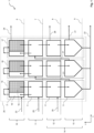
- Figure 1 shows a greatly simplified schematic representation (principle sketch) of an embodiment of the reactor according to the invention, based on which in particular Arrangement of the individual reactor elements and the flow pattern in the reactor should be explained.
- the reactor 1 has a reactor jacket 29, which surrounds all essential reactor cell elements of the reactor 1. Inlets and outlets or connections for the same can extend through the reactor jacket.
- the reactor 1 according to Figure 1 is suitable for producing methanol from synthesis gas as feed gas.
- synthesis gas is a mixture of hydrogen, carbon monoxide and carbon dioxide.
- the product gas mixture contains methanol and water, and the residual gas mixture contains unreacted synthesis gas.
- the product gas mixture can also contain condensable by-products, such as higher alcohols, ketones, ethers and esters.
- the residual gas mixture can contain non-condensable by-products and non-reactable components from the raw synthesis gas, such as methane and nitrogen.
- the reactor 1 comprises a total of three reactor cells, which according to Figure 1 are referred to as first reactor cell 15, second reactor cell 16 and third reactor cell 17. Each of the reactor cells has four different reactor cell elements.
- the reactor cell elements for each reactor cell 15, 16 or 17 are, arranged from top to bottom in the drawing, a reaction device 2, a cooling device 3, a condensation device 4 and a separation device 5.
- the reactor 1 has four reactor levels arranged parallel to one another . Arranged from top to bottom as shown in the drawing, these are the reactor levels 6, 7, 8 and 9. Reactor cell elements of the same type are each arranged on a common or the same reactor level.
- cooling devices 3 arranged on the second reactor level, which are summarized as cooling devices 11 on the second reactor level 7 are shown.
- cooling devices 11 on the second reactor level 7 are shown.
- condensation devices 4 arranged on the third reactor level, which are shown collectively as condensation devices 12 on the third reactor level 8.
- condensation devices 12 on the third reactor level 8 are shown collectively as condensation devices 12 on the third reactor level 8.
- the condensation devices 12 and separation devices 13 can also be designed as integrated phase separation devices, which are then arranged as phase separation devices 14 on a then third reactor level, this third reactor level being shown in the illustration in Figure 1 would correspond to reactor level 9.
- the reactor levels 6, 7, 8 and 9 are not to be understood as physical levels, but rather merely as virtual levels.
- the reactor cell elements of the same type are arranged in a line on this plane.
- the reactor cell elements of the same type are arranged at the same height or essentially at the same height by being arranged on the same reactor level.
- the main axis of reactor 1 runs as in Figure 1 represented in the sense of a Cartesian coordinate system along the y-axis, the extent of a reactor plane 6, 7, 8 or 9 is defined over an area which extends in the xz direction.
- the z-axis runs perpendicular to the drawing plane shown.
- the positioning of the reactor planes 6, 7, 8 or 9 extending in the xz direction, for example their height, is defined by their position on the y-axis, i.e. at the position of the main axis of the reactor.
- the arrangement of the reactor cell elements shown and according to the invention ensures that reactor cell elements of different types, which simultaneously have large temperature differences from one another during operation, are not arranged next to one another.
- the reaction device 2 of the second reactor cell 16 would, for example, be arranged next to the separation device 5 of the first reaction cell 15. This would require a lot of effort for the thermal insulation of at least one of the reactor cell elements, since the Waste heat from the reaction device would otherwise severely affect the performance and thus product yield of the separation device.
- a high degree of material stress would have to be expected between the hot reaction device and the cold separation device, both of which are in fluid communication with one another and are therefore inevitably connected to one another via lines.
- the cooling devices 11 are according to the example Figure 1 designed as a gas-gas heat exchanger.
- the cooling device 3 of the first reactor cell 15 has a feed gas inlet 20 for the entry of the fresh synthesis gas.
- the feed gas is heated against the product gas mixture and residual gas mixture emerging from the reaction device 2 by indirect heat exchange, the product gas mixture and residual gas mixture being cooled in the cooling device.
- the reaction device 2 like all reaction devices 10 on the first reactor level 6, contains a solid catalyst based, for example, on copper for converting the feed gas mixture into methanol and water.
- Each of the reaction devices 2 also has at least two different compartments 18 and 19, with the first compartment 18 arranged first in the flow direction containing no catalyst, so no reaction takes place in the first compartment 18.
- the at least second compartment arranged in the direction of flow, in the case shown the further compartments 19, are filled with the solid catalyst.
- the reaction of the feed gas mixture to form methanol and water thus takes place in the further compartments 19.
- the solid catalyst in the further compartments 19 is in a heat exchange relationship with a cooling device of the reaction device 2, which is operated with boiling boiler feed water as a cooling medium.
- the cooling device serves primarily to control the temperature of the exothermic reaction, in particular to maintain a maximum permissible temperature on the catalyst bed of the solid catalyst.
- the reaction device 2 therefore has a boiler feed water inlet 23.
- the incoming boiler feed water cools the product gas mixture that heats up due to the exothermic reaction and residual gas mixture in indirect heat exchange according to the principle of evaporative cooling.
- the boiling boiler feed water flows in the reaction device 2 from bottom to top.
- Feed gas mixture flows in the first compartment 18 from bottom to top, i.e. in the same flow direction as the cooling medium, although no cooling of the feed gas takes place in the first compartment 18.
- the feed gas is then diverted and then flows from top to bottom into the further compartments 19 filled with catalyst in the reaction device 2, whereby it is indirectly cooled with boiling boiler feed water fed in countercurrent.
- the flow guidance is designed within the reactor jacket 29 of the reactor 1 in such a way that boiler feed water flows from bottom to top in each of the reaction devices 3 and leaves it as saturated steam at the upper end of each reaction device 3.
- the reactor 1 according to the invention has a corresponding distribution and collector system, which enables this flow control.
- the product gas mixture and residual gas mixture heating up on the catalyst are cooled indirectly in countercurrent with boiling boiler feed water.
- the cooling medium, the saturated steam, brought together and heated by the collector leaves the reactor at the saturated steam outlet 24 and can be used as export steam or within the process, for example in an upstream steam reformer.
- the product gas mixture and the unreacted feed gas mixture i.e. residual gas mixture
- the cooling device 3 of the first reactor cell 15 are cooled there, as described above, in countercurrent to the feed gas mixture.
- the completely gaseous or partially condensed mixture then enters the condensation device 4, in which the product gas mixture is completely or essentially completely condensed, so that liquid reaction product, a mixture of methanol and water and condensed undesirable by-products, as well as gaseous residual gas mixture are obtained in the condensation device 4 .
- the cooling in the condensation device 4 of the first reactor cell 15 and the further reactor cells 16 and 17 takes place with indirect cooling water Heat exchange with the condensing mixture in countercurrent.
- the reactor 1 therefore has a cooling water inlet 25 and a cooling water outlet 26 on the condensation devices 12 of the reactor level 8.
- the reactor 1 also has a corresponding distribution and collector system for the cooling water used for the condensation with regard to the cooling system in the condensation devices 12, see above that fresh cooling water is available in each of the condensation devices 4 via a distributor (not shown). Used cooling water is brought together in the collector and discharged from the reactor 1 via the cooling water outlet 26.
- the mixture of condensed liquid reaction product (methanol, water, condensed by-products) and gaseous residual gas mixture (hydrogen, carbon dioxide, carbon monoxide, methane, nitrogen, non-condensed by-products) is in the separator 5 of the first reactor cell 15 into the corresponding liquid product part and into a gaseous one Part separated.
- Separation device 5 is designed, for example, as a gas-liquid separator.
- the liquid reaction product essentially methanol and water, is discharged from the separator 5.
- the liquid reaction products of the separation devices 13 at the reactor level 9 are combined and discharged from the reactor 1 as a liquid reaction product 22.
- the liquid reaction products of each reactor cell can be brought together inside or outside the reactor jacket 29, according to the example Figure 1 outside. The liquid reaction product is then sent to the necessary workup to obtain pure methanol.
- the separation device 5 of the first reactor cell 15 has a residual gas mixture outlet 21.
- the residual gas mixture cooled in the cooling device 3 and condensation device 4 is withdrawn from the separation device 5 via the residual gas mixture outlet 21 and introduced into the cooling device 3 of the second reactor cell 16, where it is in accordance with the processes in the cooling device 3 of the first reactor cell 15 is heated in countercurrent against product gas mixture and residual gas mixture from the reaction device 2 of the second reactor cell 16 by indirect heat exchange.
- the heated residual gas mixture then enters the first, empty compartment of the reaction device 2 of the second reactor cell 16, is diverted and converted into product gas mixture and residual gas mixture in the further compartments 19 of the reaction device 2 of the second reactor cell 16 on the solid catalyst.
- the further processes within the second reactor cell 16 and the third reactor cell 17 largely correspond to the processes described above with regard to the first reactor cell 15.
- Residual gas mixture withdrawn at this residual gas mixture outlet 21 can, according to one embodiment, be combined with feed gas mixture and so further utilized.
- a portion of the residual gas mixture withdrawn from the third reactor cell can be taken as purge gas.
- the purge gas can be used as fuel gas in an upstream steam reformer, or it can be fed to a pressure swing adsorption device for obtaining hydrogen.
- Figure 2 shows an example of a mechanical design of the reactor 1 according to the invention Figure 1 .
- the reactor jacket 29 is not shown here for the purpose of simplification and for reasons of clarity.
- the reactor 1 has according to Figure 2 over a total of three reactor cells and four reactor levels.
- the reactor according to Figure 2 has a main axis arranged along the y-axis, which here runs vertically.
- Three reaction devices, three cooling devices, three condensation devices and three separation devices are arranged from top to bottom on the reactor levels 6, 7, 8 and 9 arranged parallel to one another. Accordingly, the reaction devices 10 are located on the first reactor level 6, the cooling devices 11 on the second reactor level 7, the condensation devices 12 on the third reactor level and the separation devices 13 on the fourth reactor level 9.
- the vertical arrangement of the main axis of the reactor 1 enables a natural flow of the condensate from top to bottom, i.e. from the hotter ones at the top Splitting the reactor to the lower cooler parts of the reactor.
- the boiler feed water is heated within the reaction devices 10 from bottom to top.
- the feed gas enters the reactor 1 via the feed gas mixture inlet 20a on the cooling device 3 of the first reactor cell 15 and is used in the reaction device 2 of the first reactor cell 15, as described Figure 1 , implemented.
- the product gas mixture is then cooled in the cooling device 2 of the first reactor cell 15, condensed in the condensation device 4 of the first reactor cell 15 and deposited as a liquid reaction product in the separating device 5 of the first reactor cell 15.
- Residual gas separated in the separation device 5 of the first reactor cell 15 exits via the residual gas mixture outlet 21a. It is then led either via a pipeline inside the reactor jacket 29 or outside the reactor jacket 29 to the residual gas mixture inlet 20b.
- the external routing of the pipelines i.e. outside the reactor jacket 29, has the advantage that samples can easily be taken from the pipeline for analytical purposes.
- This also opens up the possibility of operating the three reactor cells 15, 16 and 17 in parallel.
- the reactor according to the invention is used according to the principle of a one-stage synthesis. However, three reactors could then be operated simultaneously, these reactors being represented here by the reactor cells 15, 16 and 17.
- the internal routing of the pipelines i.e. within the reactor jacket 29, has the advantage that fewer long pipelines are required overall, heat losses that inevitably occur are lower and there are fewer potential opportunities for leaks.
- Residual gas mixture emerging from the residual gas mixture outlet 21a then enters the cooling device 3 of the second reactor cell 16 via the residual gas mixture inlet 20b in order to first cool the product gas mixture emerging from the reaction device 2 of the reactor cell 16 there.
- the residual gas mixture is preheated and then enters the reaction device 2 of the second reactor cell 16 preheated at the top of the reactor cell 16.
- remaining residual gas mixture is withdrawn from a further residual gas mixture outlet arranged at the level of the condensation devices 12.
- This residual gas mixture outlet is arranged on the back of the reactor 1 shown and is therefore not shown (according to the reference symbol system used, this residual gas mixture outlet would have the reference number 21b).
- the residual gas withdrawn via this residual gas mixture outlet is introduced into the third reaction cell 17 via the residual gas mixture inlet 20c in accordance with what was said above.
- Residual gas separated in the separation stage 5 of the third and last reactor cell 17 is finally withdrawn via a last residual gas mixture outlet (also not shown, would correspond to residual gas mixture outlet 21c).
- This residual gas can optionally be led back to the feed gas mixture inlet 20a, so in this case it is mixed into the feed gas mixture.
- the residual gas is fed to a device for hydrogen recovery.
- feed gas mixture can also be mixed into the respective residual gas mixtures before entering the residual gas mixture inlets 20b and 20c.
- the reactor 1 has an outlet for liquid reaction product for each reactor cell. Shown accordingly is the outlet 28a for the first reactor cell 15, the outlet 28b for the second reactor cell 16 and the outlet 28b for the third and last reactor cell 17.
- the outlets for the liquid reaction product 28a, 28b and 28c are in the bottom area of the reactor 1 respectively in the bottom area of the separator devices 13 arranged.
- Each of the separating devices 13 has two connecting pieces for controlling the level of liquid reaction product in the respective separating device 5. Shown are the connecting pieces 30a of the separating device 5 of the first reactor cell 15, the connecting pieces 30b of the separating device 5 of the second reactor cell 16, and the connecting pieces 30c of the Separation device 5 of the third reactor cell 17.
- each of the cooling devices 11 has an expansion bellows 27, which is arranged upstream of the following condensation device.
- At least the reaction devices 10 and the cooling devices 11 of the reactor 1 are designed as thermoplate heat exchangers (pillow plate heat exchangers).
- the feed gas mixture or residual gas mixture flows through the reaction device between the individual thermal sheets, i.e. an area in which the catalyst bed of the solid catalyst is also located.
- the boiling boiler feed water flows through the reaction devices.
- the cooling product gas mixture and residual gas mixture flows through the cooling devices 11 between the thermal sheets, while the heating up feed gas mixture or residual gas mixture flows within the thermal sheets or cushion plates.
- This enables an aligned arrangement of the individual reaction devices and cooling devices with respect to the spaces through which the product gas mixture and residual gas mixture or cooling medium (boiler feed water, feed gas mixture or residual gas mixture) flows.
- the reactor 1 can advantageously be made particularly compact.
Landscapes
- Chemical & Material Sciences (AREA)
- Organic Chemistry (AREA)
- Chemical Kinetics & Catalysis (AREA)
- Engineering & Computer Science (AREA)
- Analytical Chemistry (AREA)
- General Chemical & Material Sciences (AREA)
- Oil, Petroleum & Natural Gas (AREA)
- Physics & Mathematics (AREA)
- Fluid Mechanics (AREA)
- Devices And Processes Conducted In The Presence Of Fluids And Solid Particles (AREA)
- Organic Low-Molecular-Weight Compounds And Preparation Thereof (AREA)
Abstract
Description
- Die Erfindung betrifft einen Reaktor, insbesondere einen Multistufen-Reaktor zum Durchführen exothermer Gleichgewichtsreaktionen mit Zwischenkondensation des Reaktionsprodukts. Die Erfindung betrifft ferner die Verwendung des erfindungsgemäßen Reaktors für die Herstellung von Methanol.
- Die
EP 3 401 299 A1 und dieEP 3 401 300 beschreiben das Prinzip eines Multistufen-Reaktors mit Zwischenkondensation, beispielsweise für die Herstellung von Methanol mit Zwischenkondensation des Rohmethanols (Methanol, Wasser und Verunreinigungen). Gemäß diesem Prinzip sind mehrere Reaktorzellen innerhalb eines gemeinsamen Mantels angeordnet, wobei jede der Reaktorzellen zumindest die eigentliche Reaktionszone, eine Abkühlzone, eine Abscheidezone sowie Mittel zum Ausleiten des abgeschiedenen Reaktionsprodukts und zum Ausleiten des nicht umgesetzten Einsatzgases umfasst. - Für die räumliche Anordnung der Reaktorzellen innerhalb des Reaktormantels wird in der
EP 3 401 299 A1 ausschließlich eine Anordnung der Reaktorzellen hintereinander in vertikaler (aufrecht stehender) oder horizontaler (liegender) Weise vorgeschlagen. - Durch einfaches hintereinander Anordnen von Reaktorzellen ergeben sich jedoch unvorteilhafte Reaktormantel-Dimensionierungen.
- Gemäß einem Beispiel ergibt sich für einen dreistufigen Reaktor eine Länge von etwa 7 Metern pro Stufe, davon ausgehend dass die Katalysatorbettlänge der Reaktionszone 4 Meter beträgt, der dahinter angeordnete Wärmeaustauscher eine Länge von etwa 1,5 Metern aufweist und der Kondensator und der Abscheider zusammen 1,5 Meter Länge in Anspruch nehmen. Diese Reaktorzellen aufeinander gestapelt ergeben bereits eine Gesamtlänge von 21 Metern.
- Vor allem bei Reaktoren mit eher kleinen Kapazitäten mit entsprechend kleinen Reaktormantel-Durchmessern ergibt sich hier ein ungünstiges Längen-Durchmesser-Verhältnis. Es bedarf eines zusätzlichen Stahlgerüsts, um die mechanische Stabilität eines derart schlanken Apparates sicherzustellen. Auch die Handhabung des Katalysators, vor allem in den unteren Reaktorzellen, ist schwierig. Die Gasführung innerhalb der und zwischen den Reaktorzellen ist komplex und erfordert komplizierte Einbauten, Rohrführung und Strömungskanäle. Bei der Verwendung von Thermoblechen als Wärmeaustauscher-Struktur (auch bezeichnet als Kissenplatten-Wärmeübertrager oder pillow plate heat exchanger) müssen jeweils einzelne Thermoblechpakete mit Verteiler (header) und Sammler (collector) gefertigt und im Mantel verbaut werden, was zu höheren Produktionskosten führt. Auch die Temperaturführung ist bei einer solchen Konfiguration nicht optimal, da beispielsweise eine heiße Reaktionszone einer zweiten Reaktorzelle in direkter Nähe einer kalten Abscheidezone der vorgelagerten, ersten Reaktorzelle liegt. Dies erfordert eine entsprechend aufwändige Isolation. Auch kann die Leistung in der Abscheidezone durch Erwärmung der flüssigen Phase im Abscheider beeinträchtigt werden, was zu Einbußen bei der Produktausbeute führt. Auch die damit einhergehenden thermischen Spannungen des verwendeten Metalls erfordert eine komplexe Bauweise, die bei der Konstruktion des Apparates berücksichtigt werden muss.
- Alternativ können die Reaktionszone, die Abkühlzone und die Abscheidezone horizontal in einem gemeinsamen Reaktormantel angeordnet werden. In Bezug auf die Gesamtlänge eines Apparates, entsprechend dem vorgenannten Beispiel, können hier Einsparungen bezüglich der Gesamtlänge des liegenden Apparates erzielt werden, wenn das Prozessgas von oben nach unten, senkrecht zur horizontalen Achse des liegenden Apparates, angeströmt wird. Entsprechend dem obigen Beispiel käme in diesem Fall eine Gesamtlänge von etwa 5,70 Metern zustande. Durch Teilung der Reaktionszonen kann der Manteldurchmesser verringert werden, dies führt jedoch zu einer verkomplizierten Prozessgasführung. Ein weiterer Lösungsansatz könnte in der horizontalen Anströmung des Reaktorbetts liegen. Hier besteht der Nachteil jedoch darin, dass durch die Katalysatorschrumpfung hervorgerufene Bypass-Strömung technisch schwierig in den Griff zu bekommen ist. Ferner ist über die Lebenszeit des Katalysators davon auszugehen, dass das Katalysatorbett im unteren Bereich der Schüttung sukzessive verdichtet, so dass sich über die Lebenszeit des Katalysators bei horizontaler Anströmung eine zunehmende Fehlverteilung des Prozessgases über das Katalysatorbett ergibt. Wie im obigen Beispiel mit vertikaler Anordnung ist auch bei horizontaler, räumlich aneinander gereihter Anordnung der Reaktorzellen die Temperaturführung mit Nachteilen behaftet und die Prozessgasführung kompliziert.
-
US 2018/0221842 A1 betrifft einen mehrstufigen Reaktor und ein System zur Herstellung von Methanol aus Synthesegas. Der Reaktor enthält einen Rohrbündelreaktor, der an seinem oberen und unteren Ende in mehrere vertikale, isolierte Kompartimente unterteilt ist. Die zugehörigen Kompartimente und Rohre bilden eine Stufe des Reaktors. Das rohe Synthesegas wird der ersten Stufe zugeführt, und das nicht umgesetzte Synthesegas aus der ersten Stufe wird der zweiten, nachfolgenden Stufe zugeführt. Zwischen den einzelnen Stufen wird das Produkt, Methanol und Wasser, aus dem Reaktionsgemisch entfernt, bevor das nicht umgesetzte Synthesegas in die nachfolgende Stufe geleitet wird. Die Wärmeaustauscher und Abscheider sind außerhalb des Reaktormantels angeordnet, was in einer komplizierten Anordnung von Leitungen und einer komplexen Prozessführung führt. - Eine Aufgabe der vorliegenden Erfindung besteht darin, die vorgenannten Nachteile des Standes der Technik zumindest teilweise zu überwinden.
- Insbesondere besteht eine Aufgabe der vorliegenden Erfindung darin, einen Reaktor bereitzustellen, der die Anordnung einer Mehrzahl von Reaktionsvorrichtungen, Abkühlvorrichtungen und Phasentrennvorrichtungen innerhalb eines kompakten Gehäuses ermöglicht.
- Eine weitere Aufgabe der vorliegenden Erfindung besteht darin, einen Reaktor bereitzustellen, der die Anordnung einer Mehrzahl von Reaktionsvorrichtungen, Abkühlvorrichtungen und Phasentrennvorrichtungen innerhalb eines gemeinsamen Reaktormantels ermöglicht.
- Eine weitere Aufgabe der vorliegenden Erfindung besteht darin, einen Reaktor bereitzustellen, welcher bei Vorhandensein einer Mehrzahl von Reaktionsvorrichtungen und Phasentrennvorrichtungen die Anordnung einer Reaktionsvorrichtung und einer Phasentrennvorrichtung direkt nebeneinander vermeidet.
- Eine weitere Aufgabe der vorliegenden Erfindung besteht darin, einen Reaktor bereitzustellen, welcher bei Vorhandensein einer Mehrzahl von Reaktionsvorrichtungen, Abkühlvorrichtungen und Phasentrennvorrichtungen ein vergleichmäßigtes Temperaturprofil über die Gesamtlänge des Reaktors ermöglicht, so dass Materialspannungen vermieden werden und kostengünstigere Materialien bezüglich der Reaktorbauteile Verwendung finden können.
- Ein Beitrag zur mindestens teilweisen Erfüllung mindestens einer der obigen Aufgaben wird durch die unabhängigen Ansprüche geleistet. Die abhängigen Ansprüche stellen bevorzugte Ausführungsformen bereit, die zur mindestens teilweisen Erfüllung mindestens einer der Aufgaben beitragen. Bevorzugte Ausgestaltungen von Bestandteilen einer erfindungsgemäßen Kategorie sind, soweit zutreffend, ebenso bevorzugt für gleichnamige oder entsprechende Bestandteile einer jeweils anderen erfindungsgemäßen Kategorie.
- Die Ausdrücke "aufweisend", "umfassend" oder "beinhaltend" etc. schließen nicht aus, dass weitere Elemente, Inhaltsstoffe etc. enthalten sein können. Der unbestimmte Artikel "ein" schließt nicht aus, dass eine Mehrzahl vorhanden sein kann.
- Gemäß einem ersten Aspekt der Erfindung wird ein Reaktor zum Durchführen exothermer Gleichgewichtsreaktionen vorgeschlagen, in dem ein Einsatzgasgemisch und/oder ein Restgasgemisch an einem festen Katalysator zumindest teilweise umsetzbar ist/sind, wobei ein Produktgasgemisch und ein Restgasgemisch erhältlich sind, wobei das Produktgasgemisch ein bei Reaktionsdruck und unterhalb der Reaktionstemperatur kondensierbares, flüssiges Reaktionsprodukt enthält, aufweisend einen Reaktormantel und eine innerhalb des Reaktormantels angeordnete Mehrzahl hintereinander geschalteter und in Fluidverbindung miteinander stehender Reaktorzellen, wobei
jede Reaktorzelle die folgenden, hintereinander geschalteten und in Fluidverbindung miteinander stehenden Reaktorzellenelemente umfasst: - Eine Reaktionsvorrichtung, konfiguriert zum Umsetzen des Einsatzgasgemischs und/oder des Restgasgemischs zum Produktgasgemisch, aufweisend den festen Katalysator und eine mit dem festen Katalysator in Wärmeaustauschbeziehung stehende und von einem Kühlmedium durchströmbare Kühlvorrichtung;
- Eine Abkühlvorrichtung, konfiguriert zum Abkühlen des aus der Reaktionsvorrichtung austretenden Produktgasgemischs;
- Eine Phasentrennvorrichtung, konfiguriert zum Kondensieren und Abscheiden des flüssigen Reaktionsprodukts aus dem abgekühlten Produktgasgemisch, wobei die kondensierte, flüssige Phase das Reaktionsprodukt und die gasförmige Phase das Restgasgemisch enthält;
- und wobei jede Reaktorzelle
- Mittel zum Ausleiten des Reaktionsprodukts aus der Reaktorzelle umfasst, und
- Mittel zum Ausleiten des Restgasgemischs aus der Reaktorzelle umfasst, und
- Mittel zum Zuführen des Restgasgemischs zu einer, soweit vorhanden, stromabwärts angeordneten Reaktorzelle umfasst;
- und wobei der Reaktor
- eine Mehrzahl innerhalb des Reaktormantels und parallel zueinander angeordnete Reaktorebenen aufweist, wobei Reaktorzellenelemente derselben Art auf derselben Reaktorebene angeordnet sind.
- Der erfindungsgemäße Reaktor ist zum Durchführen exothermer Gleichgewichtsreaktionen konfiguriert, insbesondere zum Durchführen der Synthese von Methanol im Industriemaßstab aus Synthesegas. Bei dem Einsatzgasgemisch handelt es sich insbesondere um ein Synthesegasgemisch, wobei das Synthesegasgemisch zumindest Wasserstoff als ein erstes Eduktgas aufweist, sowie zumindest Kohlenmonoxid oder Kohlendioxid als zweites Eduktgas aufweist. Insbesondere weist das Einsatzgasgemisch Wasserstoff als erstes Eduktgas, Kohlenmonoxid als zweites Eduktgas, sowie Kohlendioxid als drittes Eduktgas auf.
- Zumindest ein Teil der Reaktorzellenelemente sind mechanisch mit dem Reaktormantel verbunden. Dabei ist es nicht zwingend erforderlich, dass jedes der Reaktorzellenelemente mechanisch mit dem Reaktormantel verbunden ist. Gemäß einer Ausführungsform sind Reaktorzellenelemente untereinander durch mechanische Verbindungselemente miteinander verbunden, so dass nicht für jedes der Reaktorzellenelemente eine mechanische Verbindung zum Reaktormantel erforderlich ist. Bei der mechanischen Verbindung kann es sich um eine mechanische Stützstruktur, beispielsweise in Form einer Aufhängung oder Abstützung, handeln.
- Die Bildung des Produktgasgemischs erfolgt bei erhöhter Temperatur (Reaktionstemperatur) und bei erhöhtem Druck. Handelt es sich bei dem Reaktionsprodukt beispielsweise um Methanol und Wasser, so erfolgt die Bildung des Produktgasgemischs insbesondere bei Temperaturen von 180 °C bis 250 °C und bei Drücken von 30 bar bis 120 bar, insbesondere bei 40 bar bis 90 bar. Bezüglich der Temperatur ist dabei der Arbeitstemperaturbereich des verwendeten Katalysators zu beachten, welcher nicht unterschritten oder überschritten werden sollte. Für die Methanolsynthese kommen in der Regel dem Fachmann bekannte feste Katalysatoren auf Kupferbasis zum Einsatz.
- Das Produktgasgemisch enthält insbesondere Methanol und Wasser sowie unvermeidbare Nebenprodukte wie Ether, Ester, höhere Alkohole und Ketone, wobei das Gemisch aus Methanol, Wasser und Nebenprodukten auch als Rohmethanol bezeichnet wird. Zumindest Methanol und Wasser sind in diesem Fall die bei Reaktionsdruck und unterhalb der jeweiligen Reaktionstemperatur kondensierbaren, flüssigen Reaktionsprodukte. Da es sich bei der Bildung von Methanol und Wasser aus Synthesegas um eine Gleichgewichtsreaktion handelt, bei der sich ein thermodynamisches Gleichgewicht einstellt, wird ein Anteil des Einsatzgasgemisches, insbesondere Synthesegasgemisch, nicht zu Methanol und Wasser umgesetzt. Dieser nicht umgesetzte Anteil bildet das Restgasgemisch.
- Der erfindungsgemäße Reaktor weist einen Reaktormantel und eine innerhalb des Reaktormantels angeordnete Mehrzahl hintereinander geschalteter und in Fluidverbindung miteinander stehende Reaktorzellen auf. "Mehrzahl" bedeutet in diesem Zusammenhang, dass der Reaktor zumindest zwei Reaktorzellen umfasst. Jede Reaktorzelle bildet eine Reaktionsstufe einer Mehrstufensynthese. Mehrstufensynthese bedeutet, dass in jeder Stufe der Mehrstufensynthese die Bildung von Produktgasgemisch aus Einsatzgasgemisch und/oder Restgasgemisch am festen Katalysator und die zumindest teilweise Abtrennung des gewünschten flüssigen Reaktionsprodukts aus dem erhaltenen Produktgasgemisch erfolgt. Die Reaktorzellen sind dabei hintereinander angeordnet, das heißt die zweite Reaktorzelle ist in Gasflussrichtung stromabwärts zur ersten Reaktorzelle angeordnet, die dritte Reaktorzelle, soweit vorhanden, in Gasflussrichtung stromabwärts zur zweiten Reaktorzelle und so weiter. Die Reaktorzellen stehen dabei untereinander in Fluidverbindung. Das bedeutet insbesondere, dass ein Gasgemisch, insbesondere Restgasgemisch, welches aus einer Reaktorzelle ausgeschleust wird, anschließend in die jeweilige in Gasflussrichtung stromabwärts angeordnete Reaktorzelle eingeschleust wird.
- Das Produktgasgemisch wird in der ersten Reaktorzelle soweit abgekühlt, dass dieses zumindest teilweise kondensiert und so das flüssige Reaktionsprodukt aus der ersten Reaktorzelle ausgeschleust werden kann. Das Restgasgemisch wird zumindest teilweise in die zur ersten Reaktorzelle in Gasflussrichtung stromabwärts angeordnete Reaktorzelle eingeschleust, damit in der zweiten Reaktorzelle erneut Produktgasgemisch aus Restgasgemisch am festen Katalysator der zweiten Reaktorzelle gebildet werden kann. Gemäß einer Ausführungsform kann dem Restgasgemisch, welches in die zweite Reaktionszelle eingeschleust wird, auch ein Anteil Einsatzgasgemisch ("Frischgas") zugemischt werden. Produktgasgemisch der zweiten Reaktorzelle wird erneut soweit abgekühlt, dass aus diesem das Reaktionsprodukt zumindest teilweise kondensiert und in flüssiger Form aus der zweiten Reaktorzelle ausgeschleust werden kann. Ist eine dritte Reaktorzelle vorhanden, so wird das in der zweiten Reaktorzelle verbliebene Restgasgemisch sowie optional ein Anteil Einsatzgasgemisch in die dritte Reaktorzelle eingeschleust und so weiter.
- Jede der Mehrzahl an Reaktorzellen umfasst eine Reaktionsvorrichtung, eine Abkühlvorrichtung und eine Phasentrennvorrichtung. Bei der Reaktionsvorrichtung, der Abkühlvorrichtung, und der Phasentrennvorrichtung handelt es sich im Sinne des erfindungsgemäßen Reaktors um unterschiedliche Arten von Reaktorzellenelementen, welche jeweils innerhalb einer Reaktorzelle angeordnet sind. Jede Reaktorzelle umfasst dabei zumindest eine Reaktionsvorrichtung, eine Abkühlvorrichtung und eine Phasentrennvorrichtung.
- Bei der Reaktionsvorrichtung handelt es sich um eine Vorrichtung, welche für die Bildung des Produktgasgemischs aus dem Einsatzgasgemisch und/oder Restgasgemisch am festen Katalysator konfiguriert ist. Die Reaktionsvorrichtung weist dabei eine mit dem festen Katalysator in Wärmeaustauschbeziehung stehende Kühlvorrichtung auf. Die Kühlvorrichtung dient insbesondere der Temperaturkontrolle der exothermen Gleichgewichtsreaktion, das heißt der Abführung von Reaktionswärme. Dabei ist die Kühlvorrichtung insbesondere so konfiguriert, dass eine bestimmte festgelegte Maximaltemperatur im Katalysatorbett des festen Katalysators nicht überschritten wird. Gemäß einer Ausführungsform handelt es sich bei dem Kühlmedium um siedendes Kesselspeisewasser, wobei die Kühlung in der Reaktionsvorrichtung nach dem Prinzip der Siedekühlung erfolgt. Dabei wird aus dem siedenden Kesselspeisewasser Dampf gebildet, welcher zum Zwecke der Energierückgewinnung beispielsweise als Exportdampf genutzt werden kann. Bei dem festen Katalysator kann es sich um ein Katalysatorbett auf der Basis von Katalysatorpartikeln (Pellets) oder um einen strukturierten Katalysator, beispielsweise mit monolithischer Struktur, handeln.
- Jede der Reaktorzellen umfasst darüber hinausgehend zumindest eine Abkühlvorrichtung. Die Abkühlvorrichtung dient dem Abkühlen des aus der Reaktionsvorrichtung austretenden Produktgasgemischs. Dabei wird das Produktgasgemisch in der Abkühlvorrichtung vorzugsweise nur soweit abgekühlt, dass noch keine Kondensation des flüssigen Reaktionsprodukts erfolgt, das heißt das Reaktionsprodukt verbleibt innerhalb der Abkühlvorrichtung in der Gasphase. Bei dem Reaktionsprodukt handelt es sich insbesondere um ein Gemisch aus Methanol und Wasser, sowie gegebenenfalls weitere kondensierbare und/oder nicht kondensierbare (unerwünschte) Nebenprodukte. Innerhalb einer Reaktorzelle ist die Abkühlvorrichtung in Gasflussrichtung stromabwärts zur Reaktionsvorrichtung der gleichen Reaktorzelle angeordnet. Vorzugsweise weist die Abkühlvorrichtung eine Kühlvorrichtung auf, welche in Wärmeaustauschbeziehung mit dem aus der Reaktionsvorrichtung austretenden Produktgasgemisch steht. Insbesondere handelt es sich bei der Kühlvorrichtung um einen indirekten Wärmeaustauscher, wobei als Kühlmedium ein Gas oder eine Flüssigkeit in Frage kommen. Vorzugsweise handelt es sich bei dem Kühlmedium um das Einsatzgasgemisch oder Restgasgemisch. Handelt es sich dabei um das Einsatzgasgemisch, so wird dieses vorzugsweise der Abkühlvorrichtung der ersten Reaktorzelle als Kühlmedium zugeführt. Handelt es sich dabei um das Restgasgemisch, so wird dieses vorzugsweise einer Abkühlvorrichtung einer der zur ersten Reaktorzelle in Gasflussrichtung stromabwärts angeordneten Reaktorzelle zugeführt, also der zweiten und/oder dritten Reaktorzelle und so weiter. Insbesondere wird dieses Restgasgemisch aus der Phasentrennvorrichtung der der jeweiligen Reaktorzelle vorgeschalteten Reaktorzelle abgezogen, also aus der Phasentrennvorrichtung der ersten Reaktorzelle, um es der Abkühlvorrichtung der zweiten Reaktorzelle zuzuführen, und/oder aus der Phasentrennvorrichtung der zweiten Reaktorzelle, um es der Abkühlvorrichtung der dritten Reaktorzelle zuzuführen und so weiter.
- Jede der Reaktorzellen umfasst darüber hinausgehend zumindest eine Phasentrennvorrichtung. Die Phasentrennvorrichtung dient dem weiteren Abkühlen des in der Abkühlvorrichtung bereits vorgekühlten Produktgasgemischs, so dass das Reaktionsprodukt kondensiert und in flüssiger Form erhalten wird. Die Phasentrennvorrichtung ist somit so konfiguriert, dass eine kondensierte, flüssige Phase und eine gasförmige Phase erhalten werden. Des Weiteren dient die Phasentrennvorrichtung der Abtrennung der flüssigen Phase von der gasförmigen Phase, insbesondere des flüssigen Reaktionsprodukts von den weiteren Bestandteilen, also nicht verflüssigten, das heißt in der Phasentrennvorrichtung nicht kondensierten oder nicht kondensierbaren Bestandteilen. Handelt es sich bei dem Einsatzgasgemisch um ein Synthesegasgemisch und bei dem Zielprodukt um Methanol, so enthält die flüssige Phase als kondensiertes, flüssiges Reaktionsprodukt Methanol und Wasser, und unter den jeweiligen Bedingungen kondensierbare (unerwünschte) Nebenprodukte. Die gasförmige Phase enthält das Restgasgemisch, also nicht umgesetztes Synthesegas sowie unter den jeweiligen Bedingungen nicht kondensierbare Nebenprodukte. Nicht kondensierbare Nebenprodukte schließen auch Bestandteile ein, welche bereits im Einsatzgasgemisch enthalten sind und unter den Bedingungen der Methanolsynthese inert sind, das heißt weder zum Zielprodukt Methanol noch zu einem Nebenprodukt umgesetzt werden. Beispiele für diese Art von Nebenprodukten sind Methan und Stickstoff.
- Innerhalb einer Reaktorzelle ist die Phasentrennvorrichtung in Gasflussrichtung stromabwärts zur Abkühlvorrichtung der gleichen Reaktorzelle angeordnet. Vorzugsweise weist die Phasentrennvorrichtung eine Kühlvorrichtung auf, welche in Wärmeaustauschbeziehung mit dem aus der Abkühlvorrichtung austretenden Produktgasgemisch steht. Insbesondere handelt es sich bei der Kühlvorrichtung um einen indirekten Wärmeaustauscher, wobei als Kühlmedium vorzugsweise eine Flüssigkeit, insbesondere Kühlwasser in Frage kommt. Die Phasentrennvorrichtung weist darüber hinausgehend weiterhin vorzugsweise eine Vorrichtung zur Phasentrennung auf, insbesondere einen Gas-Flüssigkeits-Abscheider.
- Der erfindungsgemäße Reaktor weist eine Mehrzahl von Reaktorzellen auf, wobei diese Reaktorzellen hintereinander geschaltet sind. Das heißt, in Gasflussrichtung folgt auf die erste Reaktorzelle eine zweite Reaktorzelle, auf die zweite Reaktorzelle optional eine dritte Reaktorzelle und so weiter. Weist der Reaktor eine Anzahl N Reaktorzellen auf, so die erste Reaktorzelle die [N-(N-1)]-te Reaktorzelle, die zweite Reaktorzelle die [N-(N-2)]-te Reaktorzelle und so weiter, und die letzte Reaktorzelle ist die [N-(N-N)]-te oder N-te Reaktorzelle. Jede der Reaktorzellen weist zumindest eine Reaktionsvorrichtung, eine Abkühlvorrichtung, sowie eine Phasentrennvorrichtung auf, wobei die Abkühlvorrichtung jeweils in Gasflussrichtung stromabwärts zur Reaktionsvorrichtung und die Phasentrennvorrichtung jeweils stromabwärts zur Abkühlvorrichtung einer Reaktorzelle angeordnet ist. Aufgrund der Anordnung der Reaktorzellen hintereinander ist die Reaktionsvorrichtung einer zweiten Reaktorzelle dabei in Gasflussrichtung stromabwärts zur Phasentrennvorrichtung einer ersten Reaktorzelle angeordnet. Die Reaktionsvorrichtung einer dritten Reaktorzelle ist stromabwärts zur Phasentrennvorrichtung einer zweiten Reaktorzelle angeordnet und so weiter. Enthält ein erfindungsgemäßer Reaktor beispielsweise insgesamt drei Reaktorzellen, so ergibt sich für die Reihenfolge in Gasflussrichtung folgende Anordnung, angenommen dass jede Reaktorzelle eine Reaktionsvorrichtung, eine Abkühlvorrichtung und eine Phasentrennvorrichtung aufweist und jede dieser Reaktorzellenelemente als Index (in Klammern) die Nummer der Reaktorzelle trägt:
Reaktionsvorrichtung (1) → Abkühlvorrichtung (1) → Phasentrennvorrichtung (1) → Reaktionsvorrichtung (2) → Abkühlvorrichtung (2) → Phasentrennvorrichtung (2) → Reaktionsvorrichtung (3) → Abkühlvorrichtung (3) → Phasentrennvorrichtung (3). - Weist der Reaktor eine Anzahl N Reaktorzellen auf, so ergibt sich im Allgemeinen folgende Reihenfolge, angenommen dass jede Reaktorzelle eine Reaktionsvorrichtung, eine Abkühlvorrichtung und eine Phasentrennvorrichtung aufweist:
Reaktionsvorrichtung ([N-(N-1)]) → Abkühlvorrichtung ([N-(N-1)]) → Phasentrennvorrichtung ([N-(N-1)]) → Reaktionsvorrichtung ([N-(N-2)]) → Abkühlvorrichtung ([N-(N-2)]) → Phasentrennvorrichtung ([N-(N-2)]) → [...] → Reaktionsvorrichtung (([N-(N-N)]) → Abkühlvorrichtung ([N-(N-N)]) → Phasentrennvorrichtung ([N-(N-N)]). - Jede der Reaktorzellen umfasst Mittel zum Ausleiten des Reaktionsprodukts aus der jeweiligen Reaktorzelle. Insbesondere umfasst der erfindungsgemäße Reaktor Mittel zum Ausleiten des flüssigen Reaktionsprodukts aus der Phasentrennvorrichtung der jeweiligen Reaktorzelle. Das aus jeder der Reaktorzellen ausgeleitete flüssige Reaktionsprodukt, bei dem es sich insbesondere um Rohmethanol handelt, wird anschließend einer weiteren Aufarbeitung, zum Beispiel Rektifikation, zugeführt. Gemäß einer Ausführungsform werden die Ströme an flüssigem Reaktionsprodukt, welche aus jeder der Reaktorzellen ausgeleitet werden, zusammengeführt und gemeinsam einer weiteren Aufarbeitung unterzogen.
- Jede der Reaktorzellen umfasst ferner Mittel zum Ausleiten des Restgasgemischs aus der jeweiligen Reaktorzelle. Insbesondere umfasst der erfindungsgemäße Reaktor Mittel zum Ausleiten des Restgasgemischs aus der Phasentrennvorrichtung der jeweiligen Reaktorzelle. Das aus jeder der Reaktorzellen ausgeleitete Restgasgemisch enthält im Falle der Methanolsynthese insbesondere nicht umgesetztes Synthesegasgemisch, somit nicht umgesetzten Wasserstoff sowie Kohlenmonoxid und/oder Kohlendioxid. Ferner enthält das Restgasgemisch nicht kondensierbare Nebenprodukte, beispielsweise Methan und Stickstoff.
- Ferner umfasst jede der Reaktorzellen Mittel zum Zuführen des Restgasgemischs zu einer stromabwärts angeordneten Reaktorzelle, soweit eine stromabwärts angeordnete Reaktorzelle vorhanden ist. "Stromabwärts angeordnet" bedeutet in diesem Zusammenhang, dass die Reaktorzelle in Gasflussrichtung stromabwärts zur vorherigen Reaktorzelle angeordnet ist. Insbesondere umfasst jede der Reaktorzellen Mittel zum Zuführen des Restgasgemischs zu einer stromabwärts angeordneten Reaktionsvorrichtung, soweit eine stromabwärts angeordnete Reaktionsvorrichtung vorhanden ist. Handelt es sich bei der Reaktorzelle um die letzte Reaktorzelle der N Reaktorzellen, also die N-te Reaktorzelle, ist keine stromabwärts angeordnete Reaktorzelle vorhanden. An dieser Stelle nach wie vor nicht umgesetztes Restgasgemisch kann optional wieder zur ersten Reaktorzelle zurückgeführt werden. Gemäß dieser Ausführungsform weist die letzte oder N-te Reaktorzelle Mittel zum Zuführen des Restgasgemischs zur ersten oder [N-(N-1)]-ten Reaktorzelle, insbesondere zur Reaktionsvorrichtung der ersten oder [N-(N-1)]-ten Reaktorzelle auf. Gemäß einer Ausführungsform wird aus dem aus der letzten Reaktorzelle ausgeleiteten Restgas ein Purgegas abgezogen, um die Anreicherung von inerten Komponenten im Reaktor zu vermeiden.
- Erfindungsgemäß weist der Reaktor eine Mehrzahl innerhalb des Reaktormantels und parallel zueinander angeordnete Reaktorebenen auf, wobei Reaktorzellenelemente derselben Art auf derselben Reaktorebene angeordnet sind. Insbesondere ist eine Mehrzahl an Reaktorzellenelementen derselben Art auf derselben, also auf der gleichen Reaktorebene, angeordnet. Beispielsweise ist auf ein und derselben Reaktorebene eine Mehrzahl an Reaktionsvorrichtungen angeordnet, auf einer weiteren Reaktorebene eine Mehrzahl an Abkühlvorrichtungen angeordnet, und auf einer weiteren Reaktorebene ist eine Mehrzahl an Phasentrennvorrichtungen angeordnet. Unter einer Ebene ist dabei insbesondere eine Fläche zu verstehen, die sich über eine Querschnittsfläche des erfindungsgemäßen Reaktors erstreckt und senkrecht zu einer Hauptachse des Reaktors angeordnet ist. Der Reaktor weist eine Mehrzahl solcher Reaktorebenen auf, die parallel zueinander angeordnet sind. Erstreckt sich der erfindungsgemäße Reaktor beispielsweise in vertikaler Hauptrichtung und weist somit eine vertikale Hauptachse auf, so erstrecken sich die Reaktorebenen senkrecht zur Hauptachse des Reaktors in horizontaler Richtung und sind parallel zueinander übereinander angeordnet. Dabei ist unter einer Reaktorebene nicht zwangsläufig etwas dingliches, beispielsweise eine Platte zu verstehen. Unter einer "Reaktorebene" wird im Sinne der vorliegenden Erfindung auch, ohne darauf beschränkt zu sein, eine virtuelle Reaktorebene verstanden, was in Konsequenz bedeutet dass die Mehrzahl der jeweiligen Reaktorzellenelemente einer Art gemäß dem obigen Beispiel im Wesentlichen auf gleicher Höhe, also auf einer Ebene, angeordnet sind. Unter einer Reaktorebene kann erfindungsgemäß somit sowohl eine dingliche als auch eine virtuelle Reaktorebene verstanden werden.
- Durch die erfindungsgemäße Anordnung ergibt sich beispielsweise der Vorteil, dass die Reaktionsvorrichtungen grundsätzlich so beabstandet von den Phasentrennvorrichtungen angeordnet sind, dass ein Aufheizen der Medien in den Phasentrennvorrichtungen durch die Reaktionsvorrichtungen grundsätzlich vermieden wird. Da eine Abkühlvorrichtung in Gasflussrichtung stromabwärts zu einer Reaktionsvorrichtung angeordnet ist, und eine Phasentrennvorrichtung stromabwärts zu einer Abkühlvorrichtung angeordnet ist, würden sich in einem solchen Fall auf einer ersten Ebene die Reaktionsvorrichtungen befinden, auf einer zweiten Ebene die Abkühlvorrichtungen und auf einer dritten Ebene die Phasentrennvorrichtungen. Dadurch ist eine räumliche Trennung der Reaktionsvorrichtungen und der Phasentrennvorrichtungen sichergestellt.
- Durch die erfindungsgemäße Anordnung der Reaktorzellenelemente ergibt sich ferner der Vorteil einer kurzen Druckmantel Länge im Vergleich zu einer Anordnung, in welcher alle Reaktorzellenelemente entlang einer einzigen Hauptachse angeordnet wären, wobei es keine Rolle spielt ob der Reaktor dann liegend oder stehend angeordnet wäre. Gemäß der Erfindung ist das Verhältnis der Länge zum Durchmesser des Reaktors in jedem Fall kleiner und damit günstiger dimensioniert.
- Weiterhin ermöglicht die erfindungsgemäße Anordnung, dass die unterschiedlichen Reaktorzellenelemente in einer Reihenfolge von "heiß nach kalt" angeordnet werden können, wobei die auf einer Reaktorebene herrschenden Temperaturen in der Reaktorzelle im Wesentlichen gleich wären. Dadurch treten wenige bis keine Wärmespannungen in radialer Richtung des Reaktors auf. Beispielsweise kann von einer zur jeweils nächsten Reaktorebene eine Anordnung zunächst der Reaktionsvorrichtungen (heiß), dann der Abkühlvorrichtungen (kälter), und dann der Phasentrennvorrichtungen (noch kälter) erfolgen. So treten auch entlang der Hauptachse des Reaktors, beispielsweise in vertikaler Richtung, bei entsprechender Anordnung der Reaktorzellenelemente keine extremen Temperatursprünge auf, wie dies beispielsweise bei einer Nebeneinanderanordnung einer Reaktionsvorrichtung und einer Phasentrennvorrichtung der Fall wäre. Eine solche nachteilbehaftete Anordnung kann durch die erfindungsgemäße Anordnung der Reaktorzellenelemente vermieden werden.
- Die erfindungsgemäße Anordnung ermöglicht ferner einen modularen Aufbau des Reaktors, welcher eine Erweiterung um weitere Reaktorzellen zu einem späteren Zeitpunkt erlaubt.
- Eine bevorzugte Ausführungsform des erfindungsgemäßen Reaktors ist dadurch gekennzeichnet, dass auf jeder der Reaktorebenen ausschließlich eine Art eines Reaktorzellenelements angeordnet ist.
- Beispielsweise sind auf einer ersten Reaktorebene nur eine Mehrzahl an Reaktionsvorrichtungen angeordnet, auf einer zweiten Reaktorebene nur eine Mehrzahl an Abkühlvorrichtungen und auf einer dritten Reaktorebene nur eine Mehrzahl an Phasentrennvorrichtungen. Dadurch wird eine maximal kompakte Bauweise des Reaktors ermöglicht, unabhängig davon wie viele Reaktorzellen und damit einhergehend wie viele Reaktorzellenelemente der Reaktor umfasst.
- Eine bevorzugte Ausführungsform des erfindungsgemäßen Reaktors ist dadurch gekennzeichnet, dass die Zahl der vorhandenen Reaktorebenen mindestens der Zahl der vorhandenen Arten von Reaktorzellenelementen entspricht.
- Weist der erfindungsgemäße Reaktor beispielsweise drei verschiedene Arten an Reaktorzellenelementen auf, insbesondere eine Reaktionsvorrichtung, eine Abkühlvorrichtung und eine Phasentrennvorrichtung, so entspricht die Zahl der vorhandenen Reaktorebenen mindestens der Zahl der vorhandenen Arten von Reaktorzellenelemente, also der Zahl drei oder mehr, vorzugsweise drei.
- Vorzugsweise ist der erfindungsgemäße Reaktor daher dadurch gekennzeichnet, dass die Zahl der vorhandenen Reaktorebenen der Zahl der vorhandenen Arten von Reaktorzellenelementen entspricht.
- Eine bevorzugte Ausführungsform des erfindungsgemäßen Reaktors ist dadurch gekennzeichnet, dass die Reaktorzellen vertikal gegenüber der durch die Schwerkraft vermittelten Senkrechten angeordnet sind, so dass Ströme innerhalb der und zwischen den Reaktorzellenelementen von unten nach oben und von oben nach unten führbar sind.
- Die vertikale Anordnung der Reaktorzellen innerhalb des Reaktormantels führt dazu, dass sich der gesamte Reaktor aufgrund der hintereinander angeordneten unterschiedlichen Reaktorzellenelemente einer Reaktorzelle als Hauptausdehnung in vertikaler Richtung erstreckt. Gleichzeitig erstreckt sich der Reaktor weniger in horizontaler Ausdehnung. Dadurch wird für den gesamten Reaktor auch bei Vorhandensein einer Vielzahl von Reaktorzellen eine vergleichsweise geringe Aufstellfläche benötigt. Gleichzeitig ist der gesamte Reaktor auch nicht übermäßig hoch, da alle Reaktorzellenelemente der gleichen Art jeweils auf einer gemeinsamen Reaktorebene angeordnet sind.
- Eine bevorzugte Ausführungsform des erfindungsgemäßen Reaktors ist dadurch gekennzeichnet, dass die Reaktorzellenelemente innerhalb des Reaktormantels gemäß einer zweidimensionalen Matrix mit einer Anzahl y Spalten und einer Anzahl x Zeilen angeordnet sind, wobei die Anzahl y Spalten der Anzahl der Reaktorzellen entspricht, und die Anzahl x Zeilen der Anzahl der unterschiedlichen Arten von Reaktorzellenelementen entspricht, wobei eine Spalte der Matrix eine Reaktorzelle mit jeweils einer der unterschiedlichen Arten an Reaktorzellenelementen umfasst und eine Zeile der Matrix eine Reaktorebene aufweisend eine Reihe aus Reaktorzellenelementen derselben Art umfasst.
- Durch eine Anordnung der Reaktorzellenelemente im Sinne einer zweidimensionalen Matrix wird eine maximale Minimierung des durch den Reaktor beanspruchten Volumens erreicht.
- Eine bevorzugte Ausführungsform des erfindungsgemäßen Reaktors ist dadurch gekennzeichnet, dass die Reaktorebenen parallel zueinander und hintereinander von oben nach unten angeordnet sind.
- Insbesondere erstrecken sich die Reaktorebenen gemäß dieser Ausführungsform in horizontaler Richtung, so dass die Anordnung der Reaktorebenen als Stapel von horizontal angeordneten Reaktorebenen zu verstehen ist, wobei die Abstände zwischen den einzelnen Reaktorebenen im Wesentlichen der durch das jeweilige Reaktorzellenelement beanspruchten Höhe entspricht.
- Eine bevorzugte Ausführungsform des erfindungsgemäßen Reaktors ist dadurch gekennzeichnet, dass der Reaktor ein erstes Ende und ein zweites Ende aufweist, wobei auf den Reaktorebenen vom ersten Ende aus in Richtung des zweiten Endes Reaktorzellenelemente räumlich gemäß folgender Reihenfolge angeordnet sind: Reaktionsvorrichtung, Abkühlvorrichtung, Phasentrennvorrichtung.
- Zur maximalen Vereinfachung der Stromführung und zur maximalen Beabstandung der Phasentrennvorrichtungen von den Reaktionsvorrichtungen sind die einzelnen Reaktorzellenelemente innerhalb einer Reaktorzelle gemäß der obigen Reihenfolge angeordnet. Ein solcher Reaktor umfasst somit insgesamt drei Reaktorebenen, wobei die Reihenfolge der Anordnung der Reaktorzellenelemente je Reaktorzelle vom ersten Ende hin zum zweiten Ende wie folgt ist: Reaktionsvorrichtung, Abkühlvorrichtung, Phasentrennvorrichtung. Die Begriffe "erstes Ende" und "zweites Ende" sind dabei in Bezug auf die räumliche Anordnung der Reaktorzellenelemente innerhalb des Reaktormantels zu verstehen, nicht auf die Strömungsführung innerhalb des Reaktors.
- Eine bevorzugte Ausführungsform des erfindungsgemäßen Reaktors ist dadurch gekennzeichnet, dass jede Phasentrennvorrichtung eine Kondensationsvorrichtung und eine Abscheidevorrichtung umfasst, wobei die Kondensationsvorrichtungen und die Abscheidevorrichtungen jeweils auf unterschiedlichen Reaktorebenen angeordnet sind.
- Gemäß dieser Ausführungsform wird die Phasentrennvorrichtung als zwei voneinander getrennten Vorrichtungen ausgestaltet, welche untereinander in Fluidverbindung stehen. Insbesondere ist die Kondensationsvorrichtung als Kondensator ausgestaltet, welcher beispielsweise mit Kühlwasser als Kühlmedium betrieben wird. Ferner ist die Abscheidevorrichtung insbesondere als Gas-Flüssigkeits-Abscheider ausgestaltet, in welchem die Trennung des flüssigen Reaktionsprodukts von dem gasförmigen Restgasgemisch erfolgt.
- In diesem Zusammenhang ist eine bevorzugte Ausführungsform des erfindungsgemäßen Reaktors dadurch gekennzeichnet, dass der Reaktor ein erstes Ende und ein zweites Ende aufweist, wobei auf den Reaktorebenen vom ersten Ende aus in Richtung des zweiten Endes Kondensationsvorrichtungen und Abscheidevorrichtungen räumlich gemäß folgender Reihenfolge angeordnet sind: Kondensationsvorrichtungen, Abscheidevorrichtungen.
- Sind die Phasentrennvorrichtungen als getrennte Kondensationsvorrichtungen und Abscheidevorrichtungen ausgestaltet, so umfasst der Reaktor somit insgesamt vier Reaktorebenen, wobei die Reihenfolge der Anordnung der Reaktorzellenelemente je Reaktorzelle vom ersten Ende hin zum zweiten Ende wie folgt ist: Reaktionsvorrichtung, Abkühlvorrichtung, Kondensationsvorrichtung, Abscheidevorrichtung.
- Eine bevorzugte Ausführungsform des erfindungsgemäßen Reaktors ist dadurch gekennzeichnet, dass der gesamte Reaktor vertikal gegenüber der durch die Schwerkraft vermittelten Senkrechten angeordnet ist und sich das erste Ende oben befindet und das zweite Ende unten befindet.
- Eine bevorzugte Ausführungsform des erfindungsgemäßen Reaktors ist dadurch gekennzeichnet, dass die Reaktionsvorrichtungen auf einer obersten Reaktorebene angeordnet sind, die Phasentrennvorrichtungen auf einer untersten Reaktorebene angeordnet sind, und die Abkühlvorrichtungen auf einer Reaktorebene zwischen der obersten und untersten Reaktorebene angeordnet sind.
- Sind die Phasentrennvorrichtungen als getrennte Kondensationsvorrichtungen und Abscheidevorrichtungen ausgestaltet, so sind die Reaktionsvorrichtungen auf einer obersten Reaktorebene angeordnet, die Abscheidevorrichtungen sind auf einer untersten Reaktorebene angeordnet, die Abkühlvorrichtungen sind unterhalb der Reaktionsvorrichtungen angeordnet, und die Kondensationsvorrichtungen sind oberhalb der Abscheidevorrichtungen angeordnet.
- Eine bevorzugte Ausführungsform des erfindungsgemäßen Reaktors ist dadurch gekennzeichnet, dass die Abkühlvorrichtung als Gas-Gas-Wärmeaustauscher ausgestaltet ist, und wobei der Gas-Gas-Wärmeaustauscher so konfiguriert ist, dass die Abkühlung des aus der Reaktionsvorrichtung austretenden Produktgases im Gas-Gas-Wärmeaustauscher gegen einen Strom des Einsatzgasgemischs oder gegen einen Strom des Restgasgemischs erfolgt, insbesondere durch Gravitation.
- Der Gas-Gas-Wärmeaustauscher ist insbesondere als indirekter Wärmeaustauscher ausgestaltet.
- Gemäß dieser Ausführungsform wird die Wärmeintegration des Reaktors optimiert, indem das am festen Katalysator umzusetzende Einsatzgasgemisch oder Restgasgemisch durch den Strom des aus der jeweiligen Reaktionsvorrichtung austretenden Produktgasgemischs vorgewärmt wird. Da in jeder Reaktionszelle nach der Abkühlung in der Abkühlstufe eine weitere Abkühlung des Restgasgemischs in der Phasentrennvorrichtung erfolgt, insbesondere in der Kondensationsvorrichtung einer Phasentrennvorrichtung erfolgt, kann dieses gekühlte Restgasgemisch erneut als Kühlmedium in einer nachgeschalteten Reaktionszelle zum Abkühlen des aus dieser nachgeschalteten Reaktionszelle austretenden Produktgasgemischs verwendet werden.
- Eine bevorzugte Ausführungsform des erfindungsgemäßen Reaktors ist in Folge dadurch gekennzeichnet, dass der Reaktor so konfiguriert ist, dass das Einsatzgasgemisch über den Gas-Gas-Wärmeaustauscher der ersten Reaktionszelle in den Reaktor eintritt, und dabei von dem aus der Reaktionsvorrichtung der ersten Reaktorzelle austretenden Produktgasgemisch aufgeheizt wird.
- Vorzugsweise ist der der Gas-Gas-Wärmeaustauscher dabei so konfiguriert, dass der Strom des Produktgasgemischs innerhalb des Gas-Gas-Wärmeaustauschers von oben nach unten strömt und der Strom des Einsatzgasgemischs oder des Restgasgemischs innerhalb des Gas-Gas-Wärmeaustauschers von unten nach oben strömt.
- Allgemein werden durch die vertikale Anordnung der Reaktorzellen (Reaktionsvorrichtungen oben, Vorrichtungen zum Kühlen und Kondensieren weiter unten) und die Nutzung des Gegenstromprinzips die folgenden Vorteile erzielt. Zum einen wird eine optimierte Wärmeübertragung zwischen den Prozessströmen durch die Nutzung des Gegenstromprinzips erzielt. Durch das Erwärmen in Aufwärtsrichtung wird ferner die höchste Temperatur am Kopf des Reaktors erzielt, also dort wo die Reaktion des Einsatzgasgemischs erfolgen soll. Gleichzeitig wird in Abwärtsrichtung gekühlt, so dass die Temperaturen im Sumpfbereich des Reaktors am niedrigsten sind, also dort, wo die Kondensation des flüssigen Reaktionsprodukts erfolgen soll. Dies führt zwangsläufig und in vorteilhafter Weise auch zu einem Kondensieren in Abwärtsrichtung, wodurch eine natürliche Kondensat-Flussrichtung ermöglicht wird.
- Eine bevorzugte Ausführungsform des erfindungsgemäßen Reaktors ist dadurch gekennzeichnet, dass der Gas-Gas-Wärmeaustauscher als Thermoblech-Wärmeübertrager ausgestaltet ist, und der Thermoblech-Wärmeübertrager so konfiguriert ist, dass das Einsatzgasgemisch oder Restgasgemisch den Thermoblech-Wärmeübertrager innerhalb der Thermobleche durchströmt und der Produktstrom den Thermoblech-Wärmeübertrager zwischen den Thermoblechen durchströmt.
- Thermoblech-Wärmeübertrager werden alternativ auch als Kissenplatten-Wärmeübertrager (engl. pillow plate heat exchanger) bezeichnet. Entsprechend können die Thermobleche auch als Kissenplatten bezeichnet werden. Die Thermobleche sind insbesondere parallel zueinander angeordnet. Die Thermobleche sind durchströmbare Kissenplatten. Zwischen zwei insbesondere parallel zueinander angeordneten Thermoblechen befindet sich ein durchströmbarer Zwischenraum.
- Thermoblech-Wärmeübertrager ermöglichen eine besonders platzsparende Anordnung der Gas-Gas-Wärmeaustauschers innerhalb des Reaktors. Weiterhin ergeben sich durch die Verwendung von Thermoblech-Wärmeübertragern Vorteile hinsichtlich des prozessseitigen Druckverluste. Durch die Verwendung von Thermoblechen lassen sich grundsätzlich geringe Druckverluste bei gleichzeitig hohen Wärmeübertragungskoeffizienten gegenüber konventionellen Platten-Wärmeübertragern oder Rohrbündel-Wärmeübertragern erzielen.
- Eine bevorzugte Ausführungsform des erfindungsgemäßen Reaktors ist daher dadurch gekennzeichnet, dass die Reaktionsvorrichtung als Thermoblech-Wärmeübertrager ausgestaltet ist, und der Thermoblech-Wärmeübertrager so konfiguriert ist, dass das Kühlmedium der Reaktionsvorrichtung den Thermoblech-Wärmeübertrager innerhalb der Thermobleche durchströmt und der feste Katalysator zwischen den Thermoblechen des Thermoblech-Wärmeübertragers angeordnet ist, so dass das Einsatzgasgemisch den Thermoblech-Wärmeübertrager zwischen den Thermoblechen durchströmt.
- Eine weitere bevorzugte Ausführungsform des erfindungsgemäßen Reaktors ist daher dadurch gekennzeichnet, dass die Kondensationsvorrichtung als Thermoblech-Wärmeübertrager ausgestaltet ist, und der Thermoblech-Wärmeübertrager so konfiguriert ist, dass das Kühlmedium der Kondensationsvorrichtung den Thermoblech-Wärmeübertrager innerhalb der Thermobleche durchströmt, und das zu kondensierende Produktgasgemisch und das Restgasgemisch den Thermoblech-Wärmeübertrager zwischen den Thermoblechen durchströmt.
- Gemäß einer bevorzugten Ausführungsform ist die Reaktionsvorrichtung entsprechend der obigen Konfiguration als Thermoblech-Wärmeübertrager ausgestaltet, und/oder die Abkühlvorrichtung, insbesondere der Gas-Gas-Wärmeaustauscher gemäß obiger Konfiguration, ist als Thermoblech-Wärmeübertrager ausgestaltet, und/oder die Kondensationsvorrichtung ist gemäß obiger Konfiguration als Thermoblech-Wärmeübertrager ausgestaltet.
- Dabei sind vorzugsweise zumindest zwei hintereinander geschaltete Reaktorzellenelemente innerhalb einer Reaktorzelle als Thermoblech-Wärmeübertrager ausgestaltet, beispielsweise die Reaktionsvorrichtung und die Abkühlvorrichtung. Möglich ist auch, dass alle Reaktorzellenelemente als Thermoblech-Wärmeübertrager ausgestaltet sind, bei denen dies möglich ist, beispielsweise die Reaktionsvorrichtung, die Abkühlvorrichtung und die Kondensationsvorrichtung. Dadurch ergeben sich bei entsprechender Anordnung der Thermoblech-Wärmeübertrager Strömungswege in einer Flucht innerhalb jeder Reaktorzelle, und zwar im besten Fall in Bezug auf die Vorwärmung des Einsatzgasgemischs oder Restgasgemischs, die eigentliche Reaktion, und die Abkühlung sowie die Kondensation des Produktgasgemischs. Dadurch werden Strömungsverluste und Strömungswiderstände weiter reduziert, wodurch auch der Druckverlust weiter minimiert wird. Trotz kompakter Bauweise des Reaktors sind dadurch nur sehr wenige Umlenkungen der gasförmigen und flüssigen Reaktionsmedien erforderlich.
- Die Reaktionsvorrichtungen weisen jeweils ein erstes Ende und ein zweites Ende auf, und sind so konfiguriert, dass das Einsatzgasgemisch und/oder das Restgasgemisch am jeweils ersten Ende in die jeweilige Reaktionsvorrichtung eintritt und am jeweils zweiten Ende aus der jeweiligen Reaktionsvorrichtung austritt. Die Kühlvorrichtung der Reaktionsvorrichtungen ist vorzugsweise so konfiguriert, dass ein Eintrittsstutzen der Kühlvorrichtung in einem Bereich des ersten Endes oder in einem Bereich des zweiten Endes der Reaktionsvorrichtungen angeordnet ist. Ist der Eintrittsstutzen der Kühlvorrichtung in einem Bereich des ersten Endes der Reaktionsvorrichtungen angeordnet, tritt das Kühlmedium vorzugsweise erst am zweiten Ende einer jeweiligen Reaktionsvorrichtung in Wärmeaustauschbeziehung mit dem festen Katalysator. Mit anderen Worten, das Kühlmedium strömt gemäß dieser Ausführungsform zunächst vom ersten Ende der Reaktionsvorrichtung zu ihrem zweiten Ende, ohne dass das Reaktionsgemisch dabei gekühlt oder dessen Temperatur durch Wärmeübertragung kontrolliert wird. Die Kühlvorrichtung weist in diesem Fall somit eine Fluidverbindung zwischen dem Eintrittsstutzen und dem zweiten Ende der jeweiligen Reaktionsvorrichtung auf, welche nicht in Wärmeaustauschbeziehung mit dem festen Katalysator steht.
- Das Kühlmedium kann am Austrittsstutzen eine höhere Temperatur aufweisen als am Eintrittsstutzen. Insbesondere tritt das Kühlmedium als siedendes Kesselspeisewasser am Eintrittsstutzen in den Reaktor ein und als Dampf am Austrittsstutzen wieder aus.
- Die Kühlvorrichtung weist dabei optional ein Verteilersystem für die Zuführung des Kühlmediums und ein Sammlersystem für das Abführen des erhitzten Kühlmediums auf. Der Verteiler hat dabei die Aufgabe, frisches Kühlmedium, insbesondere siedendes Kesselspeisewasser, nach Eintritt über den Eintrittsstutzen auf die jeweiligen Teile der Kühlvorrichtung für die Reaktionsvorrichtungen der unterschiedlichen Reaktorzellen zu verteilen. Dem Sammlersystem kommt die Aufgabe zuteil, erhitztes Kühlmedium, insbesondere Dampf, nach Austritt aus den jeweiligen Teilen der Kühlvorrichtung für die Reaktionsvorrichtungen der unterschiedlichen Reaktorzellen zusammenzuführen. Der zusammengeführte Dampf tritt anschließend über den Austrittsstutzen der Kühlvorrichtung aus dem Reaktor aus.
- Eine bevorzugte Ausführungsform des erfindungsgemäßen Reaktors ist dadurch gekennzeichnet, dass die Reaktionsvorrichtung einer Reaktorzelle eine Mehrzahl von Kompartimenten aufweist, wobei ein erstes Kompartiment nicht mit Katalysator befüllt ist und so konfiguriert ist, dass es von unten nach oben vom Einsatzgasgemisch oder Restgasgemisch durchströmbar ist, und wobei zum ersten Kompartiment stromabwärts angeordnete Kompartimente mit Katalysator befüllt sind und so konfiguriert sind, dass sie von oben nach unten vom Einsatzgasgemisch oder Restgasgemisch durchströmbar sind.
- Vorzugsweise weist die Reaktionsvorrichtung einer Reaktorzelle eine Mehrzahl, das heißt mindestens zwei räumlich voneinander getrennte Kompartimente auf. Dabei ist das in Gasflussrichtung zuerst durchströmte Kompartiment, also das erste Kompartiment, vorzugsweise nicht mit Katalysator befüllt. Dieses Kompartiment dient in erster Linie dazu, das in der Abkühlvorrichtung, insbesondere im Gas-Gas-Wärmeaustauscher, vorgeheizte Einsatzgasgemisch oder Restgasgemisch an den Kopf des Reaktors, insbesondere an den Kopf der jeweiligen Reaktionsvorrichtung, zu transportieren. Nach einer Umlenkung dieses noch nicht umgesetzten Stroms von Einsatzgasgemisch oder Restgasgemisch durchströmt dieser das Reaktorbett des festen Katalysators vorzugsweise, bei vertikaler Anordnung des Reaktors, von oben nach unten. Dabei wird das dem ersten Kompartiment in Gasflussrichtung nachgeschaltete oder, wenn mehr als zwei Kompartimente vorhanden sind, die dem ersten Kompartiment in Gasflussrichtung nachgeschalteten Kompartimente, in der gleichen Richtung vom Einsatzgasgemisch oder Restgasgemisch durchströmt, wobei das Einsatzgasgemisch oder Restgasgemisch am festen Katalysator zu Produktgasgemisch umgesetzt wird. Gleichzeitig wird das sich durch die exotherme Reaktion aufheizende Gasgemisch im Gegenstrom durch das Kühlmedium der jeweiligen Reaktionsstufe, insbesondere siedendes Kesselspeisewasser, gekühlt. Der sich dabei auf der Kühlseite der Reaktionsstufe bildende Dampf strömt bei vertikaler Anordnung des Reaktors nach oben, was eine natürliche Dampfflussrichtung ermöglicht. Wäre auch das erste Kompartiment mit festem Katalysator gefüllt, so würde die Kühlung des Produktgasgemischs im ersten Kompartiment im Gleichstrom ablaufen, was keine effiziente Kühlung erlaubt. Oder die Flussrichtung des Kühlmediums müsste für das erste Kompartiment umgekehrt werden, was den Aufbau des Reaktors unnötig verkomplizieren würde.
- Gemäß einem weiteren Aspekt der Erfindung wird die Verwendung des erfindungsgemäßen Reaktors gemäß einer der vorgenannten Ausführungsformen zur Herstellung von Methanol aus Synthesegas vorgeschlagen, wobei das Synthesegas Kohlenstoffoxide (CO, CO2) und Wasserstoff (H2) aufweist.
- Gemäß einer Ausführungsform der erfindungsgemäßen Verwendung weist das Synthesegas kein Kohlenmonoxid oder kein Kohlendioxid auf.
- Im Hinblick auf die Reduzierung von Kohlendioxidemissionen werden insbesondere kohlenmonoxidfreie Synthesegase in Zukunft immer wichtiger. Synthesegasgemische zur Herstellung von Methanol, welche Kohlendioxid und Wasserstoff als Hauptkomponente erhalten, sind beispielsweise durch Mischen von Kohlendioxid aus Industrieabgasgen, zum Beispiel Müllheizkraftwerken, und klimaneutralem Wasserstoff (sogenanntem "blauem" Wasserstoff) möglich. Klimaneutraler Wasserstoff kann beispielsweise durch Elektrolyse von Wasser durch klimaneutralen Strom, zum Beispiel aus Windkraft, produziert werden.
- Die Erfindung wird im Folgenden durch ein Ausführungsbeispiel näher erläutert. In der folgenden detaillierten Beschreibung wird auf die beigefügten Zeichnungen verwiesen, die einen Teil des Ausführungsbeispiels bilden und in welcher illustrativ eine spezifische Ausführungsform der Erfindung dargestellt ist. In diesem Zusammenhang wird richtungsspezifische Terminologie wie "oben", "unten", "vorne", "hinten" usw. in Bezug auf die Ausrichtung der beschriebenen Figur verwendet. Da Komponenten von Ausführungsformen in einer Vielzahl von Ausrichtungen positioniert werden können, dient die richtungsspezifische Terminologie zur Veranschaulichung und ist in keiner Weise limitierend. Der Fachmann ist sich darüber im Klaren, dass andere Ausführungsformen verwendet werden können und strukturelle oder logische Änderungen vorgenommen werden können, ohne vom Schutzumfang der Erfindung abzuweichen. Die folgende detaillierte Beschreibung ist daher nicht in einem einschränkenden Sinne zu verstehen, und der Schutzumfang der Ausführungsformen wird durch die beigefügten Ansprüche definiert. Die Zeichnungen sind, soweit nicht anders angegeben, nicht zwangsläufig maßstabsgetreu.
- In der folgenden Beschreibung und in den Zeichnungen sind gleiche Elemente mit gleichen Bezugszeichen bezeichnet. Pfeile, soweit nicht mit Bezugszeichen versehen, illustrieren die Strömungsrichtung des Einsatzgasgemisches, Produktgasgemischs, Restgasgemischs, flüssigen Reaktionsproduktes oder Kombinationen davon innerhalb des erfindungsgemäßen Reaktors.
- Es zeigen
- Figur 1
- eine Prinzipskizze einer Ausführungsform des erfindungsgemäßen Reaktors, und
- Figur 2
- eine schematische Darstellung für ein Beispiel einer mechanischen Ausgestaltung des erfindungsgemäßen Reaktors.
-
Figur 1 zeigt eine stark vereinfachte schematische Darstellung (Prinzipskizze) einer Ausführungsform des erfindungsgemäßen Reaktors, anhand welcher insbesondere die Anordnung der einzelnen Reaktorelemente und der Strömungsverlauf im Reaktor erläutert werden soll. - Der Reaktor 1 verfügt über einen Reaktormantel 29, welcher alle wesentlichen Reaktorzellenelemente des Reaktors 1 umgibt. Zu- und Ableitungen oder Stutzen für dieselben können sich durch den Reaktormantel hindurch erstrecken.
- Der Reaktor 1 gemäß
Figur 1 eignet sich zur Herstellung von Methanol aus Synthesegas als Einsatzgas. Synthesegas ist im Beispiel ein Gemisch aus Wasserstoff, Kohlenmonoxid und Kohlendioxid. Bei der Umsetzung des Einsatzgases am festen Katalysator des Reaktors 1 entsteht ein Produktgasgemisch und ein Restgasgemisch. Das Produktgasgemisch enthält Methanol und Wasser, und das Restgasgemisch enthält nicht umgesetztes Synthesegas. Das Produktgasgemisch kann darüber hinaus gehend kondensierbare Nebenprodukte, wie zum Beispiel höhere Alkohole, Ketone, Ether und Ester enthalten. Das Restgasgemisch kann nicht kondensierbare Nebenprodukte und nicht umsetzbare Bestandteile aus dem Syntheserohgas, wie zum Beispiel Methan und Stickstoff, enthalten. - Der Reaktor 1 umfasst insgesamt drei Reaktorzellen, welche gemäß
Figur 1 als erste Reaktorzelle 15, zweite Reaktorzelle 16 und dritte Reaktorzelle 17 bezeichnet sind. Jede der Reaktorzellen weist vier verschiedene Reaktorzellenelemente auf. Bei den Reaktorzellenelementen je Reaktorzelle 15, 16 oder 17 handelt es sich, in der Zeichnung von oben nach unten angeordnet, um eine Reaktionsvorrichtung 2, eine Abkühlvorrichtung 3, eine Kondensationsvorrichtung 4 und eine Abscheidevorrichtung 5. Der Reaktor 1 weist vier parallel zueinander angeordnete Reaktorebenen auf. Von oben nach unten angeordnet wie in der Zeichnung dargestellt handelt es sich dabei um die Reaktorebenen 6, 7, 8 und 9. Reaktorzellenelemente der gleichen Art sind dabei jeweils auf einer gemeinsamen oder derselben Reaktorebene angeordnet. So befinden sich auf der ersten Reaktorebene angeordnet insgesamt drei Reaktionsvorrichtungen 2, welche zusammengefasst als Reaktionsvorrichtungen 10 auf der ersten Reaktorebene 6 dargestellt sind. Ferner befinden sich auf der zweiten Reaktorebene angeordnet insgesamt drei Abkühlvorrichtungen 3, welche zusammengefasst als Abkühlvorrichtungen 11 auf der zweiten Reaktorebene 7 dargestellt sind. Ferner befinden sich auf der dritten Reaktorebene angeordnet insgesamt drei Kondensationsvorrichtungen 4, welche zusammengefasst als Kondensationsvorrichtungen 12 auf der dritten Reaktorebene 8 dargestellt sind. Ferner befinden sich auf der vierten Reaktorebene angeordnet insgesamt drei Abscheidevorrichtungen 5, welche zusammengefasst als Abscheidevorrichtungen 13 auf der vierten Reaktorebene 9 dargestellt sind. Die Kondensationsvorrichtungen 12 und Abscheidevorrichtungen 13 können auch als integrierte Phasentrennvorrichtungen ausgestaltet sein, welche dann als Phasentrennvorrichtungen 14 auf einer dann dritten Reaktorebene angeordnet sind, wobei diese dritte Reaktorebene in der Darstellung inFigur 1 der Reaktorebene 9 entspräche. Die Reaktorebenen 6, 7, 8 und 9 sind gemäß der dargestellten Ausführungsform nicht als dingliche Ebenen, sondern lediglich als virtuelle Ebenen zu verstehen. Mit anderen Worten sind die Reaktorzellenelemente derselben Art in einer Linie auf dieser Ebene angeordnet. So ergibt sich beispielsweise bei vertikaler Anordnung des Reaktors 1, dass die Reaktorzellenelemente derselben Art durch Anordnung auf derselben Reaktorebene auf jeweils der gleichen Höhe oder im Wesentlichen auf der gleichen Höhe angeordnet sind. Verläuft die Hauptachse des Reaktors 1 wie inFigur 1 dargestellt im Sinne eines kartesischen Koordinatensystems entlang der y-Achse, so wird die Ausdehnung einer Reaktorebene 6, 7, 8 oder 9 über eine Fläche definiert, welche sich in x-z-Richtung erstreckt. Die z-Achse verläuft dabei senkrecht zur dargestellten Zeichenebene. Die Positionierung der sich in x-z-Richtung erstreckenden Reaktorebenen 6, 7, 8 oder 9, beispielsweise deren Höhe, wird dabei durch deren Position an der y-Achse, also an der Position der Hauptachse des Reaktors, definiert. - Durch die dargestellte und erfindungsgemäße Anordnung der Reaktorzellenelemente wird erreicht, dass Reaktorzellenelemente unterschiedlicher Art, welche im Betrieb gleichzeitig große Temperaturunterschiede zueinander aufweisen, nicht nebeneinander angeordnet sind. Bei einer rein linearen Anordnung aller drei Reaktorzellen 15, 16 und 17, mit vertikaler oder horizontaler Ausrichtung der Hauptachse, wäre beispielsweise die Reaktionsvorrichtung 2 der zweiten Reaktorzelle 16 neben der Abscheidevorrichtung 5 der ersten Reaktionszelle 15 angeordnet. Dies würde einen hohen Aufwand für die thermische Isolation zumindest eines der Reaktorzellenelemente erfordern, da die Abwärme der Reaktionsvorrichtung sonst die Leistungsfähigkeit und damit Produktausbeute der Abscheidevorrichtung stark beinträchtigen würde. Weiterhin wäre dadurch mit einem hohen Maß an Materialspannungen zwischen der heißen Reaktionsvorrichtung und der kalten Abscheidevorrichtung zu rechnen, welche beide miteinander in Fluidverbindung stehen und dadurch zwangsläufig über Leitungen miteinander verbunden sind.
- Die Abkühlvorrichtungen 11 sind im Beispiel gemäß
Figur 1 als Gas-Gas-Wärmeaustauscher ausgestaltet. Dabei verfügt die Abkühlvorrichtung 3 der ersten Reaktorzelle 15 über einen Einsatzgaseinlass 20 für den Eintritt des frischen Synthesegases. In der ersten Abkühlvorrichtung 3 der ersten Reaktorzelle 15 wird das Einsatzgas gegen das aus der Reaktionsvorrichtung 2 austretende Produktgasgemisch und Restgasgemisch durch indirekten Wärmeaustausch aufgeheizt, wobei das Produktgasgemisch und Restgasgemisch in der Abkühlvorrichtung abgekühlt wird. Nach dem Aufheizen des Einsatzgasgemischs in der Abkühlvorrichtung 3 der ersten Reaktorzelle 15 tritt dieses in die Reaktionsvorrichtung 2 ein. Die Reaktionsvorrichtung 2 enthält, wie alle Reaktionsvorrichtungen 10 auf der ersten Reaktorebene 6, einen festen Katalysator auf beispielsweise Kupfer-Basis zur Umsetzung des Einsatzgasgemischs zu Methanol und Wasser. Jede der Reaktionsvorrichtungen 2 weist darüber hinaus zumindest zwei unterschiedliche Kompartimente 18 und 19 auf, wobei das in Strömungsrichtung zuerst angeordnete, erste Kompartiment 18 keinen Katalysator enthält, im ersten Kompartiment 18 somit keine Reaktion stattfindet. Das in Strömungsrichtung zumindest zweite angeordnete Kompartiment, im gezeigten Fall die weiteren Kompartimente 19, sind mit dem festen Katalysator befüllt. In den weiteren Kompartimenten 19 findet somit die Reaktion des Einsatzgasgemischs zu Methanol und Wasser statt. Der feste Katalysator in den weiteren Kompartimenten 19 steht in Wärmeaustauschbeziehung mit einer Kühlvorrichtung der Reaktionsvorrichtung 2, welche mit siedendem Kesselspeisewasser als Kühlmedium betrieben wird. Die Kühlvorrichtung dient dabei vornehmlich der Temperaturkontrolle der exothermen Reaktion, insbesondere der Einhaltung einer maximal zulässigen Temperatur am Katalysatorbett des festen Katalysators. Die Reaktionsvorrichtung 2 verfügt daher über einen Kesselspeisewassereinlass 23. Das eintretende Kesselspeisewasser kühlt das sich durch die exotherme Reaktion aufheizende Produktgasgemisch und Restgasgemisch im indirekten Wärmeaustausch gemäß dem Prinzip der Siedekühlung. Das siedende Kesselspeisewasser strömt in der Reaktionsvorrichtung 2 dabei von unten nach oben. Einsatzgasgemisch strömt im ersten Kompartiment 18 von unten nach oben, also in gleicher Strömungsrichtung wie das Kühlmedium, wobei jedoch keine Kühlung des Einsatzgases im ersten Kompartiment 18 stattfindet. Das Einsatzgas wird anschließend umgelenkt und strömt dann in den mit Katalysator befüllten weiteren Kompartimenten 19 in der Reaktionsvorrichtung 2 von oben nach unten, wobei es mit im Gegenstrom dazu geführtem siedendem Kesselspeisewasser indirekt gekühlt wird. Die Strömungsführung ist innerhalb des Reaktormantels 29 des Reaktors 1 so ausgestaltet, dass in jeder der Reaktionsvorrichtungen 3 Kesselspeisewasser von unten nach oben strömt und am oberen Ende einer jeden Reaktionsvorrichtung 3 diese als Sattdampf verlässt. Der erfindungsgemäße Reaktor 1 verfügt über ein entsprechendes Verteiler- und Sammlersystem, welches diese Strömungsführung ermöglicht. In jeder der Reaktionsvorrichtungen 3 wird so das sich am Katalysator aufheizende Produktgasgemisch und Restgasgemisch im Gegenstrom indirekt mit siedendem Kesselspeisewasser gekühlt. Das durch den Sammler zusammengeführte und aufgeheizte Kühlmedium, der Sattdampf, verlässt den Reaktor am Sattdampfauslass 24 und kann als Exportdampf oder prozessintern, beispielsweise in einem vorgeschalteten Dampfreformer, genutzt werden. - Das Produktgasgemisch und das nicht umgesetzte Einsatzgasgemisch, also Restgasgemisch, treten anschließend in die Abkühlvorrichtung 3 der ersten Reaktorzelle 15 ein und werden dort, wie oben beschrieben, im Gegenstrom gegen Einsatzgasgemisch abgekühlt. Dabei erfolgt weitestgehend noch keine Kondensation des Produktgasgemischs zum flüssigen Reaktionsprodukt, eine Teilkondensation in der Abkühlvorrichtung 3 ist jedoch möglich. Das vollständig gasförmige oder teilkondensierte Gemisch tritt anschließend in die Kondensationsvorrichtung 4 ein, in welcher das Produktgasgemisch vollständig oder im Wesentlichen vollständig kondensiert wird, so dass flüssiges Reaktionsprodukt, ein Gemisch aus Methanol und Wasser und kondensierten unerwünschten Nebenprodukten, sowie gasförmiges Restgasgemisch in der Kondensationsvorrichtung 4 anfallen. Die Kühlung in der Kondensationsvorrichtung 4 der ersten Reaktorzelle 15 sowie den weiteren Reaktorzellen 16 und 17 erfolgt mit Kühlwasser durch indirekten Wärmeaustausch mit dem kondensierenden Gemisch im Gegenstrom. Der Reaktor 1 verfügt daher über einen Kühlwassereinlass 25 und einen Kühlwasserauslass 26 an den Kondensationsvorrichtungen 12 der Reaktorebene 8. Dabei verfügt der Reaktor 1 auch bezüglich des Kühlsystems in den Kondensationsvorrichtungen 12 über ein entsprechendes Verteiler- und Sammlersystem für das für die Kondensation verwendete Kühlwasser, so dass in jeder der Kondensationsvorrichtungen 4 frisches Kühlwasser über einen Verteiler (nicht gezeigt) zur Verfügung steht. Verbrauchtes Kühlwasser wird im Sammler zusammengeführt und über den Kühlwasserauslass 26 aus dem Reaktor 1 ausgeleitet.
- Das Gemisch aus kondensiertem flüssigem Reaktionsprodukt (Methanol, Wasser, kondensierte Nebenprodukte) und gasförmigem Restgasgemisch (Wasserstoff, Kohlendioxid, Kohlenmonoxid, Methan, Stickstoff, nicht kondensierte Nebenprodukte) wird in der Abscheidevorrichtung 5 der ersten Reaktorzelle 15 in den entsprechenden flüssigen Produktteil und in einen gasförmigen Teil getrennt. Abscheidevorrichtung 5 ist beispielsweise als Gas-Flüssigkeits-Abscheider ausgestaltet. Das flüssige Reaktionsprodukt, im Wesentlichen Methanol und Wasser, wird aus der Abscheidevorrichtung 5 ausgeleitet. Die flüssigen Reaktionsprodukte der Abscheidevorrichtungen 13 auf Reaktorebene 9 werden zusammengeführt und als flüssiges Reaktionsprodukt 22 aus dem Reaktor 1 ausgeleitet. Das Zusammenführen der flüssigen Reaktionsprodukte jeder Reaktorzelle kann dabei innerhalb oder außerhalb des Reaktormantels 29 erfolgen, im Beispiel gemäß
Figur 1 außerhalb. Das flüssige Reaktionsprodukt wird anschließend der erforderlichen Aufarbeitung zur Gewinnung von reinem Methanol zugeführt. - Die Abscheidevorrichtung 5 der ersten Reaktorzelle 15 verfügt über einen Restgasgemischauslass 21. Das in der Abkühlvorrichtung 3 und Kondensationsvorrichtung 4 abgekühlte Restgasgemisch wird über den Restgasgemischauslass 21 aus der Abscheidevorrichtung 5 abgezogen und in die Abkühlvorrichtung 3 der zweiten Reaktorzelle 16 eingeschleust, wo es entsprechend den Abläufen in der Abkühlvorrichtung 3 der ersten Reaktorzelle 15 im Gegenstrom gegen Produktgasgemisch und Restgasgemisch aus der Reaktionsvorrichtung 2 der zweiten Reaktorzelle 16 durch indirekten Wärmeaustausch aufgeheizt wird. Das aufgeheizte Restgasgemisch tritt anschließend in das erste, leere Kompartiment der Reaktionsvorrichtung 2 der zweiten Reaktorzelle 16 ein, wird umgelenkt und in den weiteren Kompartimenten 19 der Reaktionsvorrichtung 2 der zweiten Reaktorzelle 16 am festen Katalysator zu Produktgasgemisch und Restgasgemisch umgesetzt. Die weiteren Vorgänge innerhalb der zweiten Reaktorzelle 16 und der dritten Reaktorzelle 17 entsprechen weitestgehend den oben beschriebenen Abläufe bezüglich der ersten Reaktorzelle 15.
- In der dritten Reaktorzelle 17 nicht umgesetztes Synthesegas, also Restgasgemisch, verlässt den Reaktor am (dritten) Restgasgemischauslass 21 der Abscheidevorrichtung 5 dieser dritten Reaktorzelle 17. An diesem Restgasgemischauslass 21 abgezogenes Restgasgemisch kann gemäß einer Ausführungsform mit Einsatzgasgemisch zusammengeführt und so weiter verwertet werden. Um die Akkumulation von inerten Bestandteilen im System zu verhindern, kann dem aus der dritten Reaktorzelle abgezogenen Restgasgemisch ein Anteil als Spülgas (Purgegas) entnommen werden. Das Spülgas kann in einem Beispiel als Brenngas in einem vorgeschalteten Dampfreformer verwendet werden, oder es wird einer Druckwechseladsorptionvorrichtung zur Gewinnung von Wasserstoff zugeführt.
-
Figur 2 zeigt ein Beispiel für eine mechanische Ausgestaltung des erfindungsgemäßen Reaktors 1 gemäßFigur 1 . Der Reaktormantel 29 ist hier zum Zwecke der Vereinfachung und aus Gründen der Übersichtlichkeit nicht dargestellt. Entsprechend der Darstellung inFigur 1 verfügt der Reaktor 1 gemäßFigur 2 über insgesamt drei Reaktorzellen und vier Reaktorebenen. Der Reaktor gemäßFigur 2 verfügt über eine entlang der y-Achse angeordnete Hauptachse, welche hier vertikal verläuft. Von oben nach unten auf den parallel zueinander angeordneten Reaktorebenen 6, 7, 8 und 9 sind dementsprechend jeweils drei Reaktionsvorrichtungen, drei Abkühlvorrichtungen, drei Kondensationsvorrichtungen und drei Abscheidevorrichtungen angeordnet. Entsprechend befinden sich auf der ersten Reaktorebene 6 die Reaktionsvorrichtungen 10, auf der zweiten Reaktorebene 7 die Abkühlvorrichtungen 11, auf der dritten Reaktorebene die Kondensationsvorrichtungen 12 und auf der vierten Reaktorebene 9 die Abscheidevorrichtungen 13. Die vertikale Anordnung der Hauptachse des Reaktors 1 ermöglicht einen natürlichen Fluss des Kondensats von oben nach unten, also von den oberen heißeren Teilen des Reaktors zu den unteren kühleren Teilen des Reaktors. Entsprechendes gilt für den Fluss der sich aufheizenden Kühlmedien, insbesondere den Fluss des siedenden Kesselspeisewassers. Dieses tritt über den Kesselspeisewassereinlass 23 in den Reaktor 1 ein und als Sattdampf über den Sattdampfauslass 24 wieder aus dem Reaktor aus. Dabei erfolgt ein Aufheizen des Kesselspeisewassers innerhalb der Reaktionsvorrichtungen 10 jeweils von unten nach oben. Gleiches gilt für das Kühlwasser in den Kondensationsvorrichtungen 12, welches am Kühlwassereinlass 25 in den Reaktor 1 eintritt, in den Kondensationsvorrichtungen 12 jeweils von unten nach oben strömt und den Reaktor 1 am Kühlwasserauslass 26 in aufgeheizter Form verlässt. - Das Einsatzgas tritt über den Einsatzgasgemischeinlass 20a an der Abkühlvorrichtung 3 der ersten Reaktorzelle 15 in den Reaktor 1 ein und wird in der Reaktionsvorrichtung 2 der ersten Reaktorzelle 15, entsprechend der Beschreibung zur
Figur 1 , umgesetzt. Das Produktgasgemisch wird anschließend in der Abkühlvorrichtung 2 der ersten Reaktorzelle 15 abgekühlt, in der Kondensationsvorrichtung 4 der ersten Reaktorzelle 15 kondensiert und in der Abscheidevorrichtung 5 der ersten Reaktorzelle 15 als flüssiges Reaktionsprodukt abgeschieden. In der Abscheidevorrichtung 5 der ersten Reaktorzelle 15 abgeschiedenes Restgas tritt über den Restgasgemischauslass 21a aus. Es wird anschließend entweder über eine Rohrleitung innerhalb des Reaktormantels 29 oder außerhalb des Reaktormantels 29 zum Restgasgemischeinlass 20b geführt. - Die externe Führung der Rohrleitungen, also außerhalb des Reaktormantels 29, hat den Vorteil dass für analytische Zwecke leicht Proben aus der Leitung entnommen werden können. Weiterhin wird dadurch die Möglichkeit eröffnet, die drei Reaktorzellen 15, 16 und 17 parallel zu betreiben. Gemäß einer solchen Betriebsweise wird der erfindungsgemäße Reaktor gemäß dem Prinzip einer einstufigen Synthese verwendet. Es könnten dann jedoch drei Reaktoren gleichzeitig betrieben werden, wobei diese Reaktoren hier jeweils durch die Reaktorzellen 15, 16 und 17 repräsentiert werden.
- Die interne Führung der Rohrleitungen, also innerhalb des Reaktormantels 29, hat den Vorteil dass insgesamt weniger lange Rohrleitungen erforderlich sind, zwangsläufig auftretende Wärmeverluste geringer sind und weniger potentielle Möglichkeiten für Leckagen vorhanden sind.
- Aus dem Restgasgemischauslass 21a austretendes Restgasgemisch tritt anschließend über den Restgasgemischeinlass 20b in die Abkühlvorrichtung 3 der zweiten Reaktorzelle 16 ein, um dort wiederum zunächst aus der Reaktionsvorrichtung 2 der Reaktorzelle 16 austretendes Produktgasgemisch zu kühlen. Dabei wird das Restgasgemisch vorgeheizt und tritt anschließend vorgeheizt am Kopf der Reaktorzelle 16 in die Reaktionsvorrichtung 2 der zweiten Reaktorzelle 16 ein. Nach Umsetzung zum Produktgasgemisch in Reaktionsvorrichtung 2, Kühlung in Kühlvorrichtung 3, Kondensation des flüssigen Reaktionsprodukts in Kondensationsvorrichtung 4 und schließlich Abscheidung in Abscheidevorrichtung 5 der zweiten Reaktorzelle 16 wird verbleibendes Restgasgemisch aus einem weiteren auf Höhe der Kondensationsvorrichtungen 12 angeordneten Restgasgemischauslass abgezogen. Dieser Restgasgemischauslass ist auf der Rückseite des dargestellten Reaktors 1 angeordnet und daher nicht gezeigt (gemäß der verwendeten Bezugszeichensystematik hätte dieser Restgasgemischauslass das Bezugszeichen 21b). Das über diesen Restgasgemischauslass abgezogene Restgas wird entsprechend dem oben gesagten über den Restgasgemischeinlass 20c in die dritte Reaktionszelle 17 eingeschleust. In der Abscheidestufe 5 der dritten und letzten Reaktorzelle 17 abgeschiedenes Restgas wird schließlich über einen letzten Restgasgemischauslass (ebenfalls nicht gezeigt, entspräche Restgasgemischauslass 21c) abgezogen. Dieses Restgas kann optional wieder zum Einsatzgasgemischeinlass 20a geführt werde, wird in diesem Fall also dem Einsatzgasgemisch zugemischt.
- Alternativ oder zusätzlich wird das Restgas einer Vorrichtung zur Wasserstoffrückgewinnung zugeführt.
- Gemäß einer weiteren Option kann den jeweiligen Restgasgemischen vor Eintritt in die Restgasgemischeinlässe 20b und 20c auch Einsatzgasgemisch zugemischt werden.
- Der Reaktor 1 verfügt je Reaktorzelle über einen Auslass für flüssiges Reaktionsprodukt. Entsprechend gezeigt ist der Auslass 28a für die erste Reaktorzelle 15, der Auslass 28b für die zweite Reaktorzelle 16 und der Auslass 28b für die dritte und letzte Reaktorzelle 17. Die Auslässe für das flüssige Reaktionsprodukt 28a, 28b und 28c sind im Bodenbereich des Reaktors 1 beziehungsweise im Bodenbereich der Abscheidevorrichtungen 13 angeordnet. Jede der Abscheidevorrichtungen 13 verfügt über zwei Anschlussstutzen zur Regelung des Füllstands an flüssigem Reaktionsprodukt in der jeweiligen Abscheidevorrichtung 5. Gezeigt sind die Stutzen 30a der Abscheidevorrichtung 5 der ersten Reaktorzelle 15, die Stutzen 30b der Abscheidevorrichtung 5 der zweiten Reaktorzelle 16, und die Stutzen 30c der Abscheidevorrichtung 5 der dritten Reaktorzelle 17.
- Zum Ausgleich von thermischen Spannungen insbesondere in Längsrichtung verfügt jede der Abkühlvorrichtungen 11 über einen Dehnungsbalg 27, welcher jeweils stromaufwärts zur folgenden Kondensationsvorrichtung angeordnet ist.
- Zumindest die Reaktionsvorrichtungen 10 und die Abkühlvorrichtungen 11 des Reaktors 1 sind als Thermoblech-Wärmeübertrager (Kissenplatten-Wärmeübertrager) ausgestaltet. Dabei durchströmt das Einsatzgasgemisch oder Restgasgemisch die Reaktionsvorrichtung zwischen den einzelnen Thermoblechen, also einen Bereich in dem sich auch das Katalysatorbett des festen Katalysators befindet. Innerhalb der Thermobleche oder Kissenplatten werden die Reaktionsvorrichtungen von dem siedenden Kesselspeisewasser durchströmt. Entsprechend strömt das sich abkühlende Produktgasgemisch und Restgasgemisch die Abkühlvorrichtungen 11 zwischen den Thermoblechen, während das sich aufheizende Einsatzgasgemisch oder Restgasgemisch innerhalb der Thermobleche oder Kissenplatten strömt. Dies ermöglicht eine fluchtende Anordnung der einzelnen Reaktionsvorrichtungen und Abkühlvorrichtungen bezüglich der Räume, welche von Produktgasgemisch und Restgasgemisch oder Kühlmedium (Kesselspeisewasser, Einsatzgasgemisch oder Restgasgemisch) durchströmt werden. Dadurch kann der Reaktor 1 in vorteilhafter Weise besonders kompakt gebaut werden.
-
- 1
- Reaktor
- 2
- Reaktionsvorrichtung
- 3
- Abkühlvorrichtung
- 4
- Kondensationsvorrichtung
- 5
- Abscheidevorrichtung
- 6
- erste Reaktorebene
- 7
- zweite Reaktorebene
- 8
- dritte Reaktorebene
- 9
- vierte Reaktorebene
- 10
- Reaktionsvorrichtungen auf erster Reaktorebene
- 11
- Abkühlvorrichtungen auf zweiter Reaktorebene
- 12
- Kondensationsvorrichtungen auf dritter Reaktorebene
- 13
- Abscheidevorrichtungen auf vierter Reaktorebene
- 14
- Phasentrennvorrichtungen
- 15
- erste Reaktorzelle
- 16
- zweite Reaktorzelle
- 17
- dritte Reaktorzelle
- 18
- erstes, leeres Kompartiment der Reaktionsvorrichtung
- 19
- weitere, mit Katalysator befüllte Kompartimente der Reaktionsvorrichtung
- 20a,b,c
- Einsatzgasgemischeinlass oder Restgasgemischeinlass
- 21a
- Restgasgemischauslass
- 22
- flüssiges Reaktionsprodukt
- 23
- Kesselspeisewassereinlass
- 24
- Sattdampfauslass
- 25
- Kühlwassereinlass
- 26
- Kühlwasserauslass
- 27
- Dehnungsbalg
- 28a,b,c
- Auslass flüssiges Reaktionsprodukt
- 29
- Reaktormantel
- 30a,b,c
- Stutzen für Füllstandsregelung
Claims (19)
- Reaktor (1) zum Durchführen exothermer Gleichgewichtsreaktionen, in dem ein Einsatzgasgemisch und/oder ein Restgasgemisch an einem festen Katalysator zumindest teilweise umsetzbar ist/sind, wobei ein Produktgasgemisch und ein Restgasgemisch erhältlich sind, wobei das Produktgasgemisch ein bei Reaktionsdruck und unterhalb der Reaktionstemperatur kondensierbares, flüssiges Reaktionsprodukt (22) enthält, aufweisendeinen Reaktormantel (29) und eine innerhalb des Reaktormantels angeordnete Mehrzahl hintereinander geschalteter und in Fluidverbindung miteinander stehender Reaktorzellen (15, 16, 17), wobeijede Reaktorzelle die folgenden, hintereinander geschalteten und in Fluidverbindung miteinander stehenden Reaktorzellenelemente umfasst:- Eine Reaktionsvorrichtung (2), konfiguriert zum Umsetzen des Einsatzgasgemischs und/oder des Restgasgemischs zum Produktgasgemisch, aufweisend den festen Katalysator und eine mit dem festen Katalysator in Wärmeaustauschbeziehung stehende und von einem Kühlmedium durchströmbare Kühlvorrichtung;- Eine Abkühlvorrichtung (3), konfiguriert zum Abkühlen des aus der Reaktionsvorrichtung austretenden Produktgasgemischs;- Eine Phasentrennvorrichtung (14), konfiguriert zum Kondensieren und Abscheiden des flüssigen Reaktionsprodukts aus dem abgekühlten Produktgasgemisch, wobei die kondensierte, flüssige Phase das Reaktionsprodukt und die gasförmige Phase das Restgasgemisch enthält;und wobei jede Reaktorzelle- Mittel zum Ausleiten des Reaktionsprodukts aus der Reaktorzelle umfasst, und- Mittel zum Ausleiten des Restgasgemischs aus der Reaktorzelle umfasst, und- Mittel zum Zuführen des Restgasgemischs zu einer, soweit vorhanden, stromabwärts angeordneten Reaktorzelle umfasst;und wobei der Reaktor- eine Mehrzahl innerhalb des Reaktormantels und parallel zueinander angeordnete Reaktorebenen (6, 7, 8, 9) aufweist, wobei Reaktorzellenelemente derselben Art auf derselben Reaktorebene angeordnet sind.
- Reaktor nach Anspruch 1, dadurch gekennzeichnet, dass auf jeder der Reaktorebenen ausschließlich eine Art eines Reaktorzellenelements angeordnet ist.
- Reaktor nach Anspruch 1 oder 2, dadurch gekennzeichnet, dass die Zahl der vorhandenen Reaktorebenen mindestens der Zahl der vorhandenen Arten von Reaktorzellenelementen entspricht.
- Reaktor nach einem der vorherigen Ansprüche, dadurch gekennzeichnet, dass die Reaktorzellen vertikal gegenüber der durch die Schwerkraft vermittelten Senkrechten angeordnet sind, so dass Ströme innerhalb der und zwischen den Reaktorzellenelementen von unten nach oben und von oben nach unten führbar sind.
- Reaktor nach einem der vorhergehenden Ansprüche, dadurch gekennzeichnet, dass die Reaktorzellenelemente innerhalb des Reaktormantels gemäß einer zweidimensionalen Matrix mit einer Anzahl y Spalten und einer Anzahl x Zeilen angeordnet sind, wobei die Anzahl y Spalten der Anzahl der Reaktorzellen entspricht, und die Anzahl x Zeilen der Anzahl der unterschiedlichen Arten von Reaktorzellenelementen entspricht, wobei eine Spalte der Matrix eine Reaktorzelle mit jeweils einer der unterschiedlichen Arten an Reaktorzellenelementen umfasst und eine Zeile der Matrix eine Reaktorebene aufweisend eine Reihe aus Reaktorzellenelementen derselben Art umfasst.
- Reaktor nach einem der vorhergehenden Ansprüche, dadurch gekennzeichnet, dass die Reaktorebenen parallel zueinander und hintereinander von oben nach unten angeordnet sind.
- Reaktor nach einem der vorhergehenden Ansprüche, dadurch gekennzeichnet, dass der Reaktor ein erstes Ende und ein zweites Ende aufweist, wobei auf den Reaktorebenen vom ersten Ende aus in Richtung des zweiten Endes Reaktorzellenelemente räumlich gemäß folgender Reihenfolge angeordnet sind: Reaktionsvorrichtung, Abkühlvorrichtung, Phasentrennvorrichtung.
- Reaktor nach einem der vorhergehenden Ansprüche, dadurch gekennzeichnet, dass jede Phasentrennvorrichtung eine Kondensationsvorrichtung (12) und eine Abscheidevorrichtung (13) umfasst, wobei die Kondensationsvorrichtungen und die Abscheidevorrichtungen jeweils auf unterschiedlichen Reaktorebenen angeordnet sind.
- Reaktor nach Anspruch 8, dadurch gekennzeichnet, dass der Reaktor ein erstes Ende und ein zweites Ende aufweist, wobei auf den Reaktorebenen vom ersten Ende aus in Richtung des zweiten Endes Kondensationsvorrichtungen und Abscheidevorrichtungen räumlich gemäß folgender Reihenfolge angeordnet sind: Kondensationsvorrichtungen, Abscheidevorrichtungen.
- Reaktor nach einem der Ansprüche 7 bis 9, dadurch gekennzeichnet, dass der gesamte Reaktor vertikal gegenüber der durch die Schwerkraft vermittelten Senkrechten angeordnet ist und sich das erste Ende oben befindet und das zweite Ende unten befindet.
- Reaktor nach einem der vorhergehenden Ansprüche, dadurch gekennzeichnet, dass die Reaktionsvorrichtungen auf einer obersten Reaktorebene angeordnet sind, die Phasentrennvorrichtungen auf einer untersten Reaktorebene angeordnet sind, und die Abkühlvorrichtungen auf einer Reaktorebene zwischen der obersten und untersten Reaktorebene angeordnet sind.
- Reaktor nach einem der vorhergehenden Ansprüche, dadurch gekennzeichnet, dass die Abkühlvorrichtung als Gas-Gas-Wärmeaustauscher ausgestaltet ist, und wobei der Gas-Gas-Wärmeaustauscher so konfiguriert ist, dass die Abkühlung des aus der Reaktionsvorrichtung austretenden Produktgases im Gas-Gas-Wärmeaustauscher gegen einen Strom des Einsatzgasgemischs oder gegen einen Strom des Restgasgemischs erfolgt.
- Reaktor nach Anspruch 12, dadurch gekennzeichnet, dass der Gas-Gas-Wärmeaustauscher so konfiguriert ist, dass der Strom des Produktgasgemischs innerhalb des Gas-Gas-Wärmeaustauschers von oben nach unten strömt und der Strom des Einsatzgasgemischs oder des Restgasgemischs innerhalb des Gas-Gas-Wärmeaustauschers von unten nach oben strömt.
- Reaktor nach einem der Ansprüche 12 oder 13, dadurch gekennzeichnet, dass der Reaktor so konfiguriert ist, dass das Einsatzgasgemisch über den Gas-Gas-Wärmeaustauscher der ersten Reaktionszelle in den Reaktor eintritt, und dabei von dem aus der Reaktionsvorrichtung der ersten Reaktorzelle austretenden Produktgasgemisch aufgeheizt wird.
- Reaktor nach einem der Ansprüche 12 bis 14, dadurch gekennzeichnet, dass der Gas-Gas-Wärmeaustauscher als Thermoblech-Wärmeübertrager ausgestaltet ist, und der Thermoblech-Wärmeübertrager so konfiguriert ist, dass das Einsatzgasgemisch oder Restgasgemisch den Thermoblech-Wärmeübertrager innerhalb der Thermobleche durchströmt und der Produktstrom den Thermoblech-Wärmeübertrager zwischen den Thermoblechen durchströmt.
- Reaktor nach einem der vorherigen Ansprüche, dadurch gekennzeichnet, dass die Reaktionsvorrichtung als Thermoblech-Wärmeübertrager ausgestaltet ist, und der Thermoblech-Wärmeübertrager so konfiguriert ist, dass das Kühlmedium der Reaktionsvorrichtung den Thermoblech-Wärmeübertrager innerhalb der Thermobleche durchströmt und der feste Katalysator zwischen den Thermoblechen des Thermoblech-Wärmeübertragers angeordnet ist, so dass das Einsatzgasgemisch den Thermoblech-Wärmeübertrager zwischen den Thermoblechen durchströmt.
- Reaktor nach einem der vorherigen Ansprüche, dadurch gekennzeichnet, dass die Reaktionsvorrichtung einer Reaktorzelle eine Mehrzahl von Kompartimenten (18, 19) aufweist, wobei ein erstes Kompartiment (18) nicht mit Katalysator befüllt ist und so konfiguriert ist, dass es von unten nach oben vom Einsatzgasgemisch oder Restgasgemisch durchströmbar ist, und wobei zum ersten Kompartiment stromabwärts angeordnete Kompartimente (19) mit Katalysator befüllt sind und so konfiguriert sind, dass sie von oben nach unten vom Einsatzgasgemisch oder Restgasgemisch durchströmbar sind.
- Verwendung des Reaktors nach einem der vorherigen Ansprüche zur Herstellung von Methanol aus Synthesegas, wobei das Synthesegas Kohlenstoffoxide (CO, CO2) und Wasserstoff (H2) aufweist.
- Verwendung nach Anspruch 18, wobei das Synthesegas kein Kohlenmonoxid oder kein Kohlendioxid aufweist.
Priority Applications (3)
| Application Number | Priority Date | Filing Date | Title |
|---|---|---|---|
| EP22192298.2A EP4327930A1 (de) | 2022-08-26 | 2022-08-26 | Multistufenreaktor zum durchführen exothermer gleichgewichtsreaktionen |
| CN202310970205.1A CN117619289A (zh) | 2022-08-26 | 2023-08-02 | 用于进行放热平衡反应的多级反应器 |
| US18/237,960 US20240066488A1 (en) | 2022-08-26 | 2023-08-25 | Multistage reactor for performing exothermic equilibrium reactions |
Applications Claiming Priority (1)
| Application Number | Priority Date | Filing Date | Title |
|---|---|---|---|
| EP22192298.2A EP4327930A1 (de) | 2022-08-26 | 2022-08-26 | Multistufenreaktor zum durchführen exothermer gleichgewichtsreaktionen |
Publications (1)
| Publication Number | Publication Date |
|---|---|
| EP4327930A1 true EP4327930A1 (de) | 2024-02-28 |
Family
ID=83081208
Family Applications (1)
| Application Number | Title | Priority Date | Filing Date |
|---|---|---|---|
| EP22192298.2A Pending EP4327930A1 (de) | 2022-08-26 | 2022-08-26 | Multistufenreaktor zum durchführen exothermer gleichgewichtsreaktionen |
Country Status (3)
| Country | Link |
|---|---|
| US (1) | US20240066488A1 (de) |
| EP (1) | EP4327930A1 (de) |
| CN (1) | CN117619289A (de) |
Citations (7)
| Publication number | Priority date | Publication date | Assignee | Title |
|---|---|---|---|---|
| US20020048541A1 (en) * | 2000-08-17 | 2002-04-25 | Linde Aktiengesellschaft | Reactor for performing a strongly heat-conditioned catalytic reaction |
| US20080161428A1 (en) * | 2004-07-02 | 2008-07-03 | Strait Richard B | Pseudoisothermal ammonia process |
| US20120108681A1 (en) * | 2005-09-23 | 2012-05-03 | James Andrew Banister | Multiple Reactor Chemical Production System |
| WO2015030578A1 (en) * | 2013-08-27 | 2015-03-05 | Universiteit Twente | Method of preparing methanol and reactor for use in said method |
| US20180221842A1 (en) | 2015-08-10 | 2018-08-09 | Primus Green Energy Inc. | Multi-stage reactor and system for making methanol in a once-through process and methods therefor |
| EP3401299A1 (de) | 2017-05-12 | 2018-11-14 | L'air Liquide, Société Anonyme Pour L'Étude Et L'exploitation Des Procédés Georges Claude | Reaktor zum durchführen exothermer gleichgewichtsreaktionen |
| EP3401300A1 (de) | 2017-05-12 | 2018-11-14 | L'air Liquide, Société Anonyme Pour L'Étude Et L'exploitation Des Procédés Georges Claude | Verfahren zum durchführen exothermer gleichgewichtsreaktionen |
-
2022
- 2022-08-26 EP EP22192298.2A patent/EP4327930A1/de active Pending
-
2023
- 2023-08-02 CN CN202310970205.1A patent/CN117619289A/zh active Pending
- 2023-08-25 US US18/237,960 patent/US20240066488A1/en active Pending
Patent Citations (8)
| Publication number | Priority date | Publication date | Assignee | Title |
|---|---|---|---|---|
| US20020048541A1 (en) * | 2000-08-17 | 2002-04-25 | Linde Aktiengesellschaft | Reactor for performing a strongly heat-conditioned catalytic reaction |
| US20080161428A1 (en) * | 2004-07-02 | 2008-07-03 | Strait Richard B | Pseudoisothermal ammonia process |
| US20120108681A1 (en) * | 2005-09-23 | 2012-05-03 | James Andrew Banister | Multiple Reactor Chemical Production System |
| WO2015030578A1 (en) * | 2013-08-27 | 2015-03-05 | Universiteit Twente | Method of preparing methanol and reactor for use in said method |
| US20180221842A1 (en) | 2015-08-10 | 2018-08-09 | Primus Green Energy Inc. | Multi-stage reactor and system for making methanol in a once-through process and methods therefor |
| EP3401299A1 (de) | 2017-05-12 | 2018-11-14 | L'air Liquide, Société Anonyme Pour L'Étude Et L'exploitation Des Procédés Georges Claude | Reaktor zum durchführen exothermer gleichgewichtsreaktionen |
| EP3401300A1 (de) | 2017-05-12 | 2018-11-14 | L'air Liquide, Société Anonyme Pour L'Étude Et L'exploitation Des Procédés Georges Claude | Verfahren zum durchführen exothermer gleichgewichtsreaktionen |
| US10898874B2 (en) * | 2017-05-12 | 2021-01-26 | L'air Liquide Societe Anonyme Pour L'etude Et L'exploitation Des Procedes Georges Claude | Reactor for conducting exothermic equilibrium reactions |
Also Published As
| Publication number | Publication date |
|---|---|
| US20240066488A1 (en) | 2024-02-29 |
| CN117619289A (zh) | 2024-03-01 |
Similar Documents
| Publication | Publication Date | Title |
|---|---|---|
| EP3401299B1 (de) | Reaktor zum durchführen exothermer gleichgewichtsreaktionen | |
| EP1379465B1 (de) | Kompakt-dampf-reformer | |
| DE102008049622B4 (de) | Verfahren und Anlage zur Herstellung von Methanol | |
| EP3497058B1 (de) | Synthesevorrichtung und verfahren zur herstellung eines produkts | |
| DE2815856A1 (de) | Reaktor | |
| EP1773483B1 (de) | Verfahren zur durchführung heterogen katalytischer exothermer gasphasenreaktionen | |
| EP3841058B1 (de) | Verfahren zum bereitsstellen von wasserstoff | |
| DE102016110498B4 (de) | Mikroreaktor und Verfahrensführung zur Methanisierung | |
| EP3401300B1 (de) | Verfahren zur herstellung von methanol | |
| WO2023041190A1 (de) | Reaktor sowie vorrichtung und verfahren zur spaltung von ammoniak | |
| EP3416916B1 (de) | Nh3 synthesenkonfiguration für grossanlagen | |
| EP3341113B1 (de) | Reaktor und verfahren zur katalytischen umsetzung eines gasgemisches | |
| EP3233271A1 (de) | Verfahren zur durchführung einer chemischen synthese und synthesereaktor | |
| EP3808725A1 (de) | Verfahren zum mehrstufigen herstellen von methanol | |
| EP4327929A1 (de) | Methanolsynthese-plattenreaktor | |
| WO2009149809A1 (de) | Verfahren zur herstellung von formaldehyd | |
| EP1106571A1 (de) | Vorrichtung zur selektiven katalytischen Oxidation von Kohlenmonoxid | |
| EP3497057B1 (de) | Verfahren zur herstellung von ammoniak sowie ammoniaksynthesekonverter | |
| EP4327906A1 (de) | Vorrichtung mit integriertem kondensator und abscheider | |
| WO2018029083A1 (de) | Synthesevorrichtung und verfahren zur herstellung eines produkts | |
| US20240066488A1 (en) | Multistage reactor for performing exothermic equilibrium reactions | |
| EP4596490A1 (de) | Verfahren und anlage zur herstellung von wasserstoff | |
| EP4624038A1 (de) | Stützelemente mit stützplatten in einem reaktorbehälter | |
| EP4286357A1 (de) | Verfahren und anlage zur herstellung von methanol | |
| WO2025162719A1 (de) | Verfahren und anlage zur herstellung von wasserstoff |
Legal Events
| Date | Code | Title | Description |
|---|---|---|---|
| PUAI | Public reference made under article 153(3) epc to a published international application that has entered the european phase |
Free format text: ORIGINAL CODE: 0009012 |
|
| STAA | Information on the status of an ep patent application or granted ep patent |
Free format text: STATUS: THE APPLICATION HAS BEEN PUBLISHED |
|
| AK | Designated contracting states |
Kind code of ref document: A1 Designated state(s): AL AT BE BG CH CY CZ DE DK EE ES FI FR GB GR HR HU IE IS IT LI LT LU LV MC MK MT NL NO PL PT RO RS SE SI SK SM TR |
|
| STAA | Information on the status of an ep patent application or granted ep patent |
Free format text: STATUS: REQUEST FOR EXAMINATION WAS MADE |
|
| 17P | Request for examination filed |
Effective date: 20240828 |
|
| RBV | Designated contracting states (corrected) |
Designated state(s): AL AT BE BG CH CY CZ DE DK EE ES FI FR GB GR HR HU IE IS IT LI LT LU LV MC MK MT NL NO PL PT RO RS SE SI SK SM TR |