EP4327913A1 - Mist discharge device and absorption liquid-absorbing tower - Google Patents
Mist discharge device and absorption liquid-absorbing tower Download PDFInfo
- Publication number
- EP4327913A1 EP4327913A1 EP22811045.8A EP22811045A EP4327913A1 EP 4327913 A1 EP4327913 A1 EP 4327913A1 EP 22811045 A EP22811045 A EP 22811045A EP 4327913 A1 EP4327913 A1 EP 4327913A1
- Authority
- EP
- European Patent Office
- Prior art keywords
- mist
- gas
- demister
- discharge device
- protrusion
- Prior art date
- Legal status (The legal status is an assumption and is not a legal conclusion. Google has not performed a legal analysis and makes no representation as to the accuracy of the status listed.)
- Pending
Links
- 239000003595 mist Substances 0.000 title claims abstract 19
- 238000010521 absorption reaction Methods 0.000 title 1
- 230000002745 absorbent Effects 0.000 claims 6
- 239000002250 absorbent Substances 0.000 claims 6
- 239000006096 absorbing agent Substances 0.000 claims 4
- 230000005660 hydrophilic surface Effects 0.000 claims 1
- 239000000463 material Substances 0.000 claims 1
- 239000002344 surface layer Substances 0.000 claims 1
- 238000004381 surface treatment Methods 0.000 claims 1
Images



Classifications
-
- B—PERFORMING OPERATIONS; TRANSPORTING
- B01—PHYSICAL OR CHEMICAL PROCESSES OR APPARATUS IN GENERAL
- B01D—SEPARATION
- B01D53/00—Separation of gases or vapours; Recovering vapours of volatile solvents from gases; Chemical or biological purification of waste gases, e.g. engine exhaust gases, smoke, fumes, flue gases, aerosols
- B01D53/14—Separation of gases or vapours; Recovering vapours of volatile solvents from gases; Chemical or biological purification of waste gases, e.g. engine exhaust gases, smoke, fumes, flue gases, aerosols by absorption
- B01D53/18—Absorbing units; Liquid distributors therefor
-
- B—PERFORMING OPERATIONS; TRANSPORTING
- B01—PHYSICAL OR CHEMICAL PROCESSES OR APPARATUS IN GENERAL
- B01D—SEPARATION
- B01D53/00—Separation of gases or vapours; Recovering vapours of volatile solvents from gases; Chemical or biological purification of waste gases, e.g. engine exhaust gases, smoke, fumes, flue gases, aerosols
- B01D53/14—Separation of gases or vapours; Recovering vapours of volatile solvents from gases; Chemical or biological purification of waste gases, e.g. engine exhaust gases, smoke, fumes, flue gases, aerosols by absorption
- B01D53/18—Absorbing units; Liquid distributors therefor
- B01D53/185—Liquid distributors
-
- B—PERFORMING OPERATIONS; TRANSPORTING
- B01—PHYSICAL OR CHEMICAL PROCESSES OR APPARATUS IN GENERAL
- B01D—SEPARATION
- B01D47/00—Separating dispersed particles from gases, air or vapours by liquid as separating agent
- B01D47/06—Spray cleaning
-
- B—PERFORMING OPERATIONS; TRANSPORTING
- B01—PHYSICAL OR CHEMICAL PROCESSES OR APPARATUS IN GENERAL
- B01D—SEPARATION
- B01D47/00—Separating dispersed particles from gases, air or vapours by liquid as separating agent
- B01D47/14—Packed scrubbers
-
- B—PERFORMING OPERATIONS; TRANSPORTING
- B01—PHYSICAL OR CHEMICAL PROCESSES OR APPARATUS IN GENERAL
- B01D—SEPARATION
- B01D53/00—Separation of gases or vapours; Recovering vapours of volatile solvents from gases; Chemical or biological purification of waste gases, e.g. engine exhaust gases, smoke, fumes, flue gases, aerosols
- B01D53/14—Separation of gases or vapours; Recovering vapours of volatile solvents from gases; Chemical or biological purification of waste gases, e.g. engine exhaust gases, smoke, fumes, flue gases, aerosols by absorption
-
- B—PERFORMING OPERATIONS; TRANSPORTING
- B01—PHYSICAL OR CHEMICAL PROCESSES OR APPARATUS IN GENERAL
- B01D—SEPARATION
- B01D53/00—Separation of gases or vapours; Recovering vapours of volatile solvents from gases; Chemical or biological purification of waste gases, e.g. engine exhaust gases, smoke, fumes, flue gases, aerosols
- B01D53/14—Separation of gases or vapours; Recovering vapours of volatile solvents from gases; Chemical or biological purification of waste gases, e.g. engine exhaust gases, smoke, fumes, flue gases, aerosols by absorption
- B01D53/1456—Removing acid components
- B01D53/1475—Removing carbon dioxide
-
- B—PERFORMING OPERATIONS; TRANSPORTING
- B01—PHYSICAL OR CHEMICAL PROCESSES OR APPARATUS IN GENERAL
- B01D—SEPARATION
- B01D2247/00—Details relating to the separation of dispersed particles from gases, air or vapours by liquid as separating agent
- B01D2247/04—Regenerating the washing fluid
-
- B—PERFORMING OPERATIONS; TRANSPORTING
- B01—PHYSICAL OR CHEMICAL PROCESSES OR APPARATUS IN GENERAL
- B01D—SEPARATION
- B01D2247/00—Details relating to the separation of dispersed particles from gases, air or vapours by liquid as separating agent
- B01D2247/10—Means for removing the washing fluid dispersed in the gas or vapours
-
- B—PERFORMING OPERATIONS; TRANSPORTING
- B01—PHYSICAL OR CHEMICAL PROCESSES OR APPARATUS IN GENERAL
- B01D—SEPARATION
- B01D2257/00—Components to be removed
- B01D2257/50—Carbon oxides
- B01D2257/504—Carbon dioxide
-
- B—PERFORMING OPERATIONS; TRANSPORTING
- B01—PHYSICAL OR CHEMICAL PROCESSES OR APPARATUS IN GENERAL
- B01D—SEPARATION
- B01D2258/00—Sources of waste gases
- B01D2258/02—Other waste gases
- B01D2258/0283—Flue gases
Definitions
- the present disclosure relates to a mist discharge device and an absorbent absorber.
- a moisture separator including a wire mesh layer has been conventionally known (see Patent Literature 1, for example). Droplets contained in wet steam flowing through the wire mesh layer adhere to the wire mesh, whereby the wire mesh layer separates the droplets from the wet steam.
- the moisture separator includes a drain receiver configured to receive drain water, that is, the droplets separated by the wire mesh layer.
- the drain receiver extends in a direction inclined with respect to the horizontal direction along the wire mesh layer and is configured to receive the drain water from the wire mesh layer and guide the drain water to the outside of the wire mesh layer in the horizontal direction.
- Patent Literature 1 Japanese Patent Application Laid-open No. 2016-150297
- the flow direction of the wet steam flowing through the wire mesh layer of the moisture separator in Patent Literature 1 is in agreement with the horizontal direction, and the drain water flows down the wire mesh layer toward the lower side in the vertical direction.
- gas flowing through a demister configured to trap a mist flows from the lower side toward the upper side in the vertical direction.
- the mist trapped by the demister accumulates, as drain water, in the demister.
- the drain water accumulates in an upper portion of the demister. In this case, there is a possibility that a mist re-scatters from the accumulated drain water.
- an object of the present disclosure is to provide a mist discharge device capable of suppressing re-scattering of mist and an absorbent absorber.
- a mist discharge device is configured to discharge a mist trapped by a demister.
- the demister is disposed in a gas flow path allowing gas to flow from a lower side to an upper side in a vertical direction, the demister having a lower side serving as an inlet side of the gas and an upper side serving as an outlet side of the gas, the demister being configured to trap the mist contained in the gas.
- the mist discharge device includes a protrusion protruding downward from the inlet side of the demister.
- An absorbent absorber includes: an absorber body to which CO 2 -containing gas is supplied; an absorbent supply unit configured to supply an absorbent to the absorber body; a demister disposed downstream from an absorbent supply point of the absorbent supply unit of the absorber body in a flow direction of the gas, and configured to trap a mist containing a CO 2 -containing absorbent; and the above-described mist discharge device to discharge the mist trapped by the demister.
- constituents in the following embodiments may include constituents that are easily substitutable by those skilled in the art or have substantially the same configurations.
- constituents described below can be appropriately combined, and when there are a plurality of embodiments, the embodiments can be appropriately combined.
- FIG. 1 is a schematic diagram of a CO 2 capture system according to a first embodiment.
- FIG. 2 is a schematic diagram illustrating a demister and a mist discharge device according to the first embodiment.
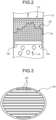
- FIG. 3 is a perspective view of the mist discharge device.
- FIG. 4 is a schematic cross-sectional view of the mist discharge device.
- FIG. 5 is a diagram illustrating various dimensions in FIG. 4 .
- FIG. 6 is a graph illustrating the performance of different types of mist discharge devices.
- the CO 2 capture system is configured to remove carbon dioxide (CO 2 ) from gas in a CO 2 absorber (an absorbent absorber) by using a CO 2 absorption component as an absorption component for absorbing CO 2 and regenerate a CO 2 absorbent in an absorbent regenerator.
- CO 2 carbon dioxide
- a CO 2 capture system 10 includes: a CO 2 absorber (hereinafter, referred to as "the absorber") 13 including a CO 2 absorber unit (hereinafter, referred to as “the absorber unit”) 13A configured to allow CO 2 -containing introduced gas (hereinafter, referred to as “the gas”) 11 to be introduced thereinto and bring CO 2 contained in the gas into contact with a CO 2 absorbent 12 to remove the CO 2 ; an absorbent regenerator (hereinafter, referred to as “the regenerator”) 14 configured to regenerate a CO 2 absorbent 12 having absorbed CO 2 , namely, a rich solution 12A by steam from a reboiler 61; a rich solution supply line 50 configured to extract the rich solution 12A from the absorber 13 and introduce the rich solution 12A into the regenerator 14; and a lean solution supply line (absorbent supply unit) 53 configured to extract, from the regenerator 14, the CO 2 absorbent which is regenerated in the
- the rich solution 12A having absorbed CO 2 and the lean solution 12B from which CO 2 has been released are circulated and reused in the CO 2 capture system.
- descriptions about the CO 2 capture system according to the present embodiment are only an outline of the CO 2 capture system, and accordingly, descriptions about attachments of the CO 2 capture system will be partially omitted.
- the gas 11 containing CO 2 is cooled by cooling water in a cooling unit and then supplied to the absorber 13.
- the gas 11 introduced by a gas introduction line 13c is brought into countercurrent contact with the CO 2 absorbent 12 containing an amine-based CO 2 absorption component, and CO 2 in the gas 11 is absorbed into the CO 2 absorbent 12 through chemical reaction.
- a mist of CO 2 -free flue gas 11A from which CO 2 has been removed is trapped by a demister 110 and then discharged from a top 13a of the absorber 13 to the system.
- the demister 110 will be described later.
- a water washing unit 20 is provided between the CO 2 absorber unit 13A and the demister 110 inside the absorber 13.
- the water washing unit 20 includes a gas-liquid contact unit 21 and a washing liquid circulator 22.
- the gas-liquid contact unit 21 is configured to bring washing water into gas-liquid contact with the gas 11 entrained in the CO 2 absorbent having passed through the CO 2 absorber unit 13A and absorbed CO 2 and trap the CO 2 absorbent 12 contained in the gas 11 by using the washing water.
- the washing liquid circulator 22 includes a washing water receiver 23, a circulation line 24, a pump 25, a washing water supply unit 26, and a cooling unit 27.
- the washing water receiver 23 is disposed upstream from the gas-liquid contact unit 21 in the gas flow, that is, disposed vertically below the gas-liquid contact unit 21.
- the washing water receiver 23 is configured to trap washing water having passed through the gas-liquid contact unit 21 and fallen into the washing water receiver 23.
- the circulation line 24 is configured to connect the washing water receiver 23 to the washing water supply unit 26, outside the absorber 13.
- the pump 25 is installed in the circulation line 24 and configured to send washing water in a predetermined direction.
- the washing water supply unit 26 is disposed downstream from the gas-liquid contact unit 21 in the gas flow, that is, disposed vertically above the gas-liquid contact unit 21.
- the washing water supply unit 26 is configured to supply, into the absorber 13, a washing liquid supplied by the circulation line 24. The supplied washing liquid falls into the gas-liquid contact unit 21.
- the washing water supply unit 26 supplies the washing liquid by injecting in a spraying manner, for example.
- the cooling unit 27 is installed in the circulation line 24 and configured to cool washing water.
- the water washing unit 20 supplies the washing liquid from above the gas-liquid contact unit and recovers the washing liquid from below and circulates the washing liquid, and thereby traps the absorbent contained in the gas 11.
- the gas having passed through the water washing unit 20 is such that the gas 11 entrains a part of the washing liquid including the absorbent. In other words, the gas having passed through the water washing unit 20 entrains a mist containing the CO 2 absorbent.
- the demister 110 is configured to trap the mist containing the CO 2 absorbent.
- the CO 2 capture system 10 extracts the rich solution 12A having absorbed CO 2 , from a bottom 13b of the absorber 13 by means of a rich solution supply line 50.
- the CO 2 capture system 10 pressurizes the rich solution 12A by using a rich solution pump 51, and heats the rich solution 12A with the lean solution 12B regenerated in the regenerator 14 in a rich-and-lean solutions heat exchanger 52 disposed on the intersection of the rich solution supply line 50 and a lean solution supply line 53, and then supplies the rich solution 12A to the regenerator 14.
- the rich solution 12A is released from a rich solution introduction unit 14a disposed in the upper part of the regenerator 14 to the inside of the regenerator 14.
- the regenerator 14 causes the release of most of CO 2 inside the regenerator 14 by an endothermic reaction between the rich solution 12A and steam supplied from the bottom of the regenerator 14 by the reboiler 61.
- the CO 2 absorbent becomes a semi-lean solution.
- the semi-lean solution becomes the CO 2 absorbent (lean solution) 12B from which almost all the CO 2 has been removed.
- part of the lean solution 12B is heated by the reboiler 61 to which saturated steam 62 is supplied, whereby steam is supplied to the inside of the regenerator 14.
- the entrained gas 41 including, as main components, steam and CO 2 released from the rich solution 12A and the semi-lean solution in the regenerator 14 is trapped by the demister 110 and then discharged from a top 14c of the regenerator 14.
- the entrained gas 41 is supplied to a regenerator condensing unit 40.
- the regenerator condensing unit 40 is configured to cool the entrained gas by a cooler 42 to condense steam, and separate the resultant into in-regenerator condensed water (hereinafter, referred to as "the condensed water") 44 and CO 2 gas 45 in a gas-liquid separator 43.
- the regenerator condensing unit 40 injects the separated CO 2 gas 45 into an oil field, for example, by enhanced oil recovery (EOR) or stores the separated CO 2 gas 45 in an aquifer.
- EOR enhanced oil recovery
- the regenerated CO 2 absorbent (lean solution) 12B is extracted from the bottom 14b of the regenerator 14 by the lean solution supply line 53, cooled with the rich solution 12A in the rich-and-lean solutions heat exchanger 52, and subsequently subjected to pressurization by the lean solution pump 54, and further cooled by a lean solution cooler 55, and then supplied to the absorber 13.
- the regenerator condensing unit 40 configured to condense moisture from the entrained gas 41 discharged from the top 14c of the regenerator 14 is disposed outside the regenerator.
- the regenerator condensing unit 40 includes: a discharge line 40a configured to discharge the entrained gas 41 from the top 14c of the regenerator 14; the cooler 42 interposed in the discharge line 40a; the gas-liquid separator 43 configured to separate the CO 2 gas 45 and the condensed water 44 produced by condensing steam by the cooler 42; a reflux line 40b configured to reflux the condensed water 44 to the top side of the regenerator; and a reflux water circulation pump 46 interposed in the reflux line 40b.
- the condensed water 44 separated from the entrained gas 41 and refluxed by the gas-liquid separator 43 is introduced, by the reflux water circulation pump 46, from a condensed water introduction unit 14d disposed closer to the top 14c of the regenerator 14 than the rich solution introduction unit 14a of the regenerator 14.
- the CO 2 capture system 10 introduces the gas 11 containing CO 2 into the absorber 13 and brings the CO 2 in the gas 11 into contact with the CO 2 absorbent 12 to remove the CO 2 .
- the gas having been supplied to the absorber 13 and brought into contact with the CO 2 absorbent 12 passes through the demister 110 and is discharged out of the system.
- the CO 2 capture system 10 introduces the rich solution 12A having absorbed CO 2 into the regenerator 14 and regenerates CO 2 by using reboiler steam.
- the entrained gas 41 in the regenerator 14 passes through the demister 110 and is supplied to the regenerator condensing unit 40.
- the CO 2 capture system 10 causes the CO 2 absorbent 12 to circulate through the absorber 13 and the regenerator 14 by means of a circulation line and be reused.
- the CO 2 capture system 10 condenses water, in the regenerator condensing unit 40, from the entrained gas 41 entraining the separated CO 2 .
- the CO 2 capture system 10 separates the condensed water 44 resulting from cooling the entrained gas 41 and thereby condensing steam and the CO 2 gas 45.
- the CO 2 capture system 10 refluxes the condensed water 44 on a side closer to the top 14c of the regenerator 14 than to the rich solution introduction unit 14a thereof into which the rich solution 12A is introduced.
- the demister 110 which is installed in the absorber 13, will be described.
- the demister 110 is disposed in a circular absorber body 112.
- the absorber body 112 serves as a gas flow path in the absorber through which the flue gas 11A flows.
- the absorber body 112 according to the first embodiment has a cylindrical shape having a circular cross-section. Note that the shape of the absorber body 112 is not limited to the above-mentioned cylindrical shape, and may have a rectangular cross-section, for example.
- the absorber body 112 vertically extends, and the flue gas 11A flows from the lower side to the upper side in the vertical direction.
- the demister 110 includes a laminated unit 120 configured to trap a mist including the CO 2 absorbent.
- the laminated unit 120 includes a plurality of layers, each layer including a plurality of linear structures.
- the mist discharge device 130 As illustrated in FIGS. 2 to 4 , the mist discharge device 130 is disposed on the lower side of the demister 110, that is, disposed to be in contact with the demister 110 on the inlet side of the demister 110 that allows the flue gas 11A to flow in therethrough.
- the mist discharge device 130 guides the drain water W accumulating in the demister 110 to the lower side in the vertical direction, whereby the drain water W falls under its own weight.
- the mist discharge device 130 includes a plurality of protrusions 135 protruding downward from the inlet side of the demister 110.
- Each of the protrusions 135 is a plate-like member extending downward and includes a plate having a vertical plane and a horizontal plane.
- the protrusions 135 are disposed to be horizontally spaced at predetermined intervals.
- the protrusions 135 as the plate-like members are disposed so that the plates thereof are disposed in parallel.
- the mist discharge device 130 includes a drain outlet in the shape of slits, as illustrated in FIG. 3 .
- Each of the protrusions 135 has a rectangular cross-section perpendicular to the plate, as illustrated in FIG. 4 .
- the protrusions 135 are disposed to be in contact with the demister 110.
- the protrusions 135 guide the drain water W in the demister 110 toward the lower side in the vertical direction.
- the protrusions 135 may be configured to be hydrophilic in order to accelerate the guiding of the drain water W.
- the protrusions 135 may be formed using a hydrophilic material.
- the protrusions 135 are formed using a material with a smaller contact angle than the demister 110 has. Examples of the material with the smaller contact angle include nylon, which is a thermoplastic resin that can be easily molded.
- the protrusions 135 may have a surface layer formed by a hydrophilic surface treatment.
- the surface layer is, for example, a coating film formed by applying a glassy coating having a small contact angle.
- a parameter for the performance to be compared is a pressure loss in the absorber body 112. Taking a case without the mist discharge device 130 as 1, the ratio of pressure loss of each of the types is used as the parameter.
- the dimensions of the mist discharge device 130 are the protrusion height (a) of the protrusion 135, the thickness (b) of the protrusion 135, and the interval (c) between the protrusions 135 adjacent to each other.
- the types of the mist discharge devices 130 are "ID5", “ID7”, and “ID8”. In “ID 5", the protrusion height (a) is 6 mm, the thickness (b) is 2 mm, and the interval (c) is 2 mm. In “ID 7", the protrusion height (a) is 1 mm, the thickness (b) is 2 mm, and the interval (c) is 4 mm.
- the protrusion height (a) is 1 mm
- the thickness (b) is 4 mm
- the interval (c) is 4 mm. Note that the interval (c) between the protrusions 135 in any of the mist discharge devices 130 is wider than the mesh size of a mesh in the demister 110.
- the horizontal axis indicates a type, and the vertical axis indicates the ratio of pressure loss (pressure loss ratio).
- ID4 is a case without the mist discharge device 130, in which the pressure loss ratio is taken as 1.
- ID5 the pressure loss ratio is lower than 0.5.
- ID7 the pressure loss ratio is lower than 0.5.
- ID8 the pressure loss ratio is lower than 0.5.
- different types of the demisters 110 (meshes) are used, and in any of the types, the pressure loss ratio is lower than 0.5.
- FIG. 7 is a schematic cross-sectional view of a mist discharge device according to the second embodiment.
- a mist discharge device 150 includes protrusions 151 having a shape different from that in the first embodiment.
- the protrusions 151 are formed in such a manner that the flow direction of (a mist of) drain water W flowing down the protrusions 151 is inclined with respect to the vertical direction.
- the cross section of the protrusion 151 taken perpendicularly to the plate, has a tapered shape that tapers down from the upper side of the protrusion 151 to the lower side thereof.
- the tapered shape may be, for example, triangular or trapezoidal, and is not particularly limited.
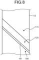
- FIG. 8 is a schematic diagram illustrating a mist discharge device according to the third embodiment.
- a mist discharge device 160 includes a protrusion 161 formed in such a manner that the flow direction of (a mist of) drain water W flowing down the protrusion 161 is inclined with respect to the vertical direction.
- the protrusion 161 is inclined with respect to the horizontal direction so as to produce an inclined flow in a single direction from one end of the protrusion 161 to the other end thereof.
- the mist discharge device 160 is disposed to be inclined with respect to the horizontal direction.
- the protrusion 161 which is a plate-like member, is disposed to extend with an inclination in such a manner that one horizontal end of the protrusion 161 is positioned on the upper side and the other horizontal end thereof is positioned on the lower side.
- the drain water W flowing down the protrusion 161 flows in the direction of the inclination of the protrusion 161.
- the protrusions 135, 151, and 161 are plate-like members, but may be rod-like members extending downward, or may have any shape protruding downward without causing a blockage in the absorber body 112.
- mist discharge devices 130, 150, 160 and the absorbent absorber 13 described in the embodiments are understood, for example, as follows.
- Each of the mist discharge devices 130, 150, and 160 is a mist discharge device configured to discharge a mist trapped by the demister 110, in which the demister 110 is disposed in a gas flow path (the absorber body 112) allowing gas to flow from the lower side to the upper side in the vertical direction, has a lower side serving as the inlet side of the gas and has an upper side serving as the outlet side of the gas, and is configured to trap the mist contained in the gas, and the mist discharge devices 130, 150, and 160 respectively include the protrusions 135, 151, 161 protruding downward from the inlet side of the demister 110.
- the mist trapped by the demister 110 flows down the protrusions 135 and is discharged to the outside of the demister 110.
- the mist can be suitably discharged to the outside of the demister 110, whereby accumulation of mist in the demister 110 can be suppressed, and thus re-scattering of the mist from the accumulated drain water can be suppressed.
- the protrusions 135, 151, 161 are plate-like members extending downward, and a plurality of the plate-like members are disposed to be horizontally spaced at predetermined intervals.
- the mist can be suitably discharged with a simple structure.
- the protrusions 135, 151, 161 have a surface layer formed by a hydrophilic surface treatment.
- the protrusions 135, 151, 161 are formed using a hydrophilic material.
- the protrusions 151, 161 are formed in such a manner that the flow direction of the mist flowing down the protrusions 135, 151, 161 is inclined with respect to the vertical direction.
- the mist flows down the protrusions 151, 161 in an inclined manner, whereby discharging the mist can be suitably accelerated.
- the protrusion 151 has a tapered shape that tapers down from the upper side of the protrusion 151 to the lower side thereof.
- the simple shape allows the mist to flow in an inclination direction.
- the protrusion 161 is inclined with respect to the horizontal direction so as to produce an inclined flow in a single direction from one end of the protrusion 161 to the other end thereof.
- the inclination of the protrusion 161 allows the mist to easily flow down in a single direction.
- the absorbent absorber 13 includes: the absorber body 112 to which CO 2 -containing gas is supplied; an absorbent supply unit (the lean solution supply line 53) configured to supply an absorbent to the absorber body 112; the demister 110 disposed downstream from an absorbent supply point of the absorbent supply unit of the absorber body 112 in the gas flow direction and configured to trap a mist containing a CO 2 -containing adsorbent; and the mist discharge device 130, 150, or 160 configured to discharge the mist trapped by the demister 110.
- an absorbent supply unit the lean solution supply line 53
- the demister 110 disposed downstream from an absorbent supply point of the absorbent supply unit of the absorber body 112 in the gas flow direction and configured to trap a mist containing a CO 2 -containing adsorbent
- the mist discharge device 130, 150, or 160 configured to discharge the mist trapped by the demister 110.
- the absorbent absorber 13 can suppress re-scattering of mist.
Landscapes
- Chemical & Material Sciences (AREA)
- Chemical Kinetics & Catalysis (AREA)
- Engineering & Computer Science (AREA)
- Analytical Chemistry (AREA)
- General Chemical & Material Sciences (AREA)
- Oil, Petroleum & Natural Gas (AREA)
- Gas Separation By Absorption (AREA)
- Treating Waste Gases (AREA)
Abstract
Description
- The present disclosure relates to a mist discharge device and an absorbent absorber.
- A moisture separator including a wire mesh layer has been conventionally known (see
Patent Literature 1, for example). Droplets contained in wet steam flowing through the wire mesh layer adhere to the wire mesh, whereby the wire mesh layer separates the droplets from the wet steam. The moisture separator includes a drain receiver configured to receive drain water, that is, the droplets separated by the wire mesh layer. The drain receiver extends in a direction inclined with respect to the horizontal direction along the wire mesh layer and is configured to receive the drain water from the wire mesh layer and guide the drain water to the outside of the wire mesh layer in the horizontal direction. - Patent Literature 1:
Japanese Patent Application Laid-open No. 2016-150297 - Here, the flow direction of the wet steam flowing through the wire mesh layer of the moisture separator in
Patent Literature 1 is in agreement with the horizontal direction, and the drain water flows down the wire mesh layer toward the lower side in the vertical direction. On the other hand, gas flowing through a demister configured to trap a mist flows from the lower side toward the upper side in the vertical direction. When the gas flows from the lower side toward the upper side, the mist trapped by the demister accumulates, as drain water, in the demister. At this time, if the drain water is not properly discharged, the drain water accumulates in an upper portion of the demister. In this case, there is a possibility that a mist re-scatters from the accumulated drain water. - Therefore, an object of the present disclosure is to provide a mist discharge device capable of suppressing re-scattering of mist and an absorbent absorber.
- A mist discharge device according to the present disclosure is configured to discharge a mist trapped by a demister. The demister is disposed in a gas flow path allowing gas to flow from a lower side to an upper side in a vertical direction, the demister having a lower side serving as an inlet side of the gas and an upper side serving as an outlet side of the gas, the demister being configured to trap the mist contained in the gas. The mist discharge device includes a protrusion protruding downward from the inlet side of the demister.
- An absorbent absorber according to the present disclosure includes: an absorber body to which CO2-containing gas is supplied; an absorbent supply unit configured to supply an absorbent to the absorber body; a demister disposed downstream from an absorbent supply point of the absorbent supply unit of the absorber body in a flow direction of the gas, and configured to trap a mist containing a CO2-containing absorbent; and the above-described mist discharge device to discharge the mist trapped by the demister.
- According to the present disclosure, re-scattering of mist can be suppressed.
-
-
FIG. 1 is a schematic diagram of a CO2 capture system according to a first embodiment. -
FIG. 2 is a schematic diagram illustrating a demister and a mist discharge device according to the first embodiment. -
FIG. 3 is a perspective view of the mist discharge device. -
FIG. 4 is a schematic cross-sectional view of the mist discharge device. -
FIG. 5 is a diagram illustrating various dimensions inFIG. 4 . -
FIG. 6 is a graph illustrating the performance of different types of mist discharge devices. -
FIG. 7 is a schematic cross-sectional view of a mist discharge device according to a second embodiment. -
FIG. 8 is a schematic diagram illustrating a mist discharge device according to a third embodiment. Description of Embodiments - Hereinafter, embodiments according to the present disclosure will be described in detail with reference to the drawings. Note that the present invention is not limited to the embodiments. In addition, constituents in the following embodiments may include constituents that are easily substitutable by those skilled in the art or have substantially the same configurations. Furthermore, the constituents described below can be appropriately combined, and when there are a plurality of embodiments, the embodiments can be appropriately combined.
-
FIG. 1 is a schematic diagram of a CO2 capture system according to a first embodiment.FIG. 2 is a schematic diagram illustrating a demister and a mist discharge device according to the first embodiment.FIG. 3 is a perspective view of the mist discharge device.FIG. 4 is a schematic cross-sectional view of the mist discharge device.FIG. 5 is a diagram illustrating various dimensions inFIG. 4 .FIG. 6 is a graph illustrating the performance of different types of mist discharge devices. First, the CO2 capture system will be described with reference toFIG. 1 . - The CO2 capture system according to the first embodiment is configured to remove carbon dioxide (CO2) from gas in a CO2 absorber (an absorbent absorber) by using a CO2 absorption component as an absorption component for absorbing CO2 and regenerate a CO2 absorbent in an absorbent regenerator.
- As illustrated in
FIG. 1 , a CO2 capture system 10 according to the first embodiment includes: a CO2 absorber (hereinafter, referred to as "the absorber") 13 including a CO2 absorber unit (hereinafter, referred to as "the absorber unit") 13A configured to allow CO2-containing introduced gas (hereinafter, referred to as "the gas") 11 to be introduced thereinto and bring CO2 contained in the gas into contact with a CO2 absorbent 12 to remove the CO2; an absorbent regenerator (hereinafter, referred to as "the regenerator") 14 configured to regenerate a CO2 absorbent 12 having absorbed CO2, namely, arich solution 12A by steam from areboiler 61; a richsolution supply line 50 configured to extract therich solution 12A from theabsorber 13 and introduce therich solution 12A into theregenerator 14; and a lean solution supply line (absorbent supply unit) 53 configured to extract, from theregenerator 14, the CO2 absorbent which is regenerated in theregenerator 14 and from which CO2 has been released, namely, alean solution 12B, and introduce thelean solution 12B to theabsorber 13 and reuse thelean solution 12B as a CO2 absorbent. As the CO2 absorbent 12, therich solution 12A having absorbed CO2 and thelean solution 12B from which CO2 has been released are circulated and reused in the CO2 capture system. Note that descriptions about the CO2 capture system according to the present embodiment are only an outline of the CO2 capture system, and accordingly, descriptions about attachments of the CO2 capture system will be partially omitted. - The
gas 11 containing CO2 is cooled by cooling water in a cooling unit and then supplied to theabsorber 13. In theabsorber 13, thegas 11 introduced by agas introduction line 13c is brought into countercurrent contact with the CO2 absorbent 12 containing an amine-based CO2 absorption component, and CO2 in thegas 11 is absorbed into the CO2 absorbent 12 through chemical reaction. In theabsorber 13, a mist of CO2-free flue gas 11A from which CO2 has been removed is trapped by ademister 110 and then discharged from atop 13a of theabsorber 13 to the system. Thedemister 110 will be described later. - A
water washing unit 20 is provided between the CO2 absorber unit 13A and thedemister 110 inside theabsorber 13. Thewater washing unit 20 includes a gas-liquid contact unit 21 and awashing liquid circulator 22. The gas-liquid contact unit 21 is configured to bring washing water into gas-liquid contact with thegas 11 entrained in the CO2 absorbent having passed through the CO2 absorber unit 13A and absorbed CO2 and trap the CO2 absorbent 12 contained in thegas 11 by using the washing water. Thewashing liquid circulator 22 includes awashing water receiver 23, acirculation line 24, apump 25, a washingwater supply unit 26, and acooling unit 27. Thewashing water receiver 23 is disposed upstream from the gas-liquid contact unit 21 in the gas flow, that is, disposed vertically below the gas-liquid contact unit 21. Thewashing water receiver 23 is configured to trap washing water having passed through the gas-liquid contact unit 21 and fallen into thewashing water receiver 23. Thecirculation line 24 is configured to connect thewashing water receiver 23 to the washingwater supply unit 26, outside theabsorber 13. Thepump 25 is installed in thecirculation line 24 and configured to send washing water in a predetermined direction. The washingwater supply unit 26 is disposed downstream from the gas-liquid contact unit 21 in the gas flow, that is, disposed vertically above the gas-liquid contact unit 21. The washingwater supply unit 26 is configured to supply, into theabsorber 13, a washing liquid supplied by thecirculation line 24. The supplied washing liquid falls into the gas-liquid contact unit 21. The washingwater supply unit 26 supplies the washing liquid by injecting in a spraying manner, for example. The coolingunit 27 is installed in thecirculation line 24 and configured to cool washing water. As described above, thewater washing unit 20 supplies the washing liquid from above the gas-liquid contact unit and recovers the washing liquid from below and circulates the washing liquid, and thereby traps the absorbent contained in thegas 11. The gas having passed through thewater washing unit 20 is such that thegas 11 entrains a part of the washing liquid including the absorbent. In other words, the gas having passed through thewater washing unit 20 entrains a mist containing the CO2 absorbent. Thedemister 110 is configured to trap the mist containing the CO2 absorbent. - Furthermore, the CO2 capture system 10 extracts the
rich solution 12A having absorbed CO2, from a bottom 13b of theabsorber 13 by means of a richsolution supply line 50. The CO2 capture system 10 pressurizes therich solution 12A by using arich solution pump 51, and heats therich solution 12A with thelean solution 12B regenerated in theregenerator 14 in a rich-and-leansolutions heat exchanger 52 disposed on the intersection of the richsolution supply line 50 and a leansolution supply line 53, and then supplies therich solution 12A to theregenerator 14. - The
rich solution 12A is released from a richsolution introduction unit 14a disposed in the upper part of theregenerator 14 to the inside of theregenerator 14. Theregenerator 14 causes the release of most of CO2 inside theregenerator 14 by an endothermic reaction between therich solution 12A and steam supplied from the bottom of theregenerator 14 by thereboiler 61. When releasing a part or most of CO2 inside theregenerator 14, then the CO2 absorbent becomes a semi-lean solution. By the time the semi-lean solution reaches a bottom 14b of theregenerator 14, the semi-lean solution becomes the CO2 absorbent (lean solution) 12B from which almost all the CO2 has been removed. In therich solution 12A, part of thelean solution 12B is heated by thereboiler 61 to which saturatedsteam 62 is supplied, whereby steam is supplied to the inside of theregenerator 14. - In the
regenerator 14, a mist of entrained gas (hereinafter, referred to as "the entrained gas") 41 including, as main components, steam and CO2 released from therich solution 12A and the semi-lean solution in theregenerator 14 is trapped by thedemister 110 and then discharged from a top 14c of theregenerator 14. - The entrained
gas 41 is supplied to aregenerator condensing unit 40. Theregenerator condensing unit 40 is configured to cool the entrained gas by a cooler 42 to condense steam, and separate the resultant into in-regenerator condensed water (hereinafter, referred to as "the condensed water") 44 and CO2 gas 45 in a gas-liquid separator 43. Theregenerator condensing unit 40 injects the separated CO2 gas 45 into an oil field, for example, by enhanced oil recovery (EOR) or stores the separated CO2 gas 45 in an aquifer. - The regenerated CO2 absorbent (lean solution) 12B is extracted from the bottom 14b of the
regenerator 14 by the leansolution supply line 53, cooled with therich solution 12A in the rich-and-leansolutions heat exchanger 52, and subsequently subjected to pressurization by thelean solution pump 54, and further cooled by a lean solution cooler 55, and then supplied to theabsorber 13. - In the first embodiment, the
regenerator condensing unit 40 configured to condense moisture from the entrainedgas 41 discharged from the top 14c of theregenerator 14 is disposed outside the regenerator. Theregenerator condensing unit 40 includes: adischarge line 40a configured to discharge the entrainedgas 41 from the top 14c of theregenerator 14; the cooler 42 interposed in thedischarge line 40a; the gas-liquid separator 43 configured to separate the CO2 gas 45 and thecondensed water 44 produced by condensing steam by the cooler 42; areflux line 40b configured to reflux the condensedwater 44 to the top side of the regenerator; and a refluxwater circulation pump 46 interposed in thereflux line 40b. Thecondensed water 44 separated from the entrainedgas 41 and refluxed by the gas-liquid separator 43 is introduced, by the refluxwater circulation pump 46, from a condensedwater introduction unit 14d disposed closer to the top 14c of theregenerator 14 than the richsolution introduction unit 14a of theregenerator 14. - The CO2 capture system 10 introduces the
gas 11 containing CO2 into theabsorber 13 and brings the CO2 in thegas 11 into contact with the CO2 absorbent 12 to remove the CO2. The gas having been supplied to theabsorber 13 and brought into contact with the CO2 absorbent 12 passes through thedemister 110 and is discharged out of the system. Furthermore, the CO2 capture system 10 introduces therich solution 12A having absorbed CO2 into theregenerator 14 and regenerates CO2 by using reboiler steam. The entrainedgas 41 in the regenerator 14 passes through thedemister 110 and is supplied to theregenerator condensing unit 40. The CO2 capture system 10 causes the CO2 absorbent 12 to circulate through theabsorber 13 and theregenerator 14 by means of a circulation line and be reused. The CO2 capture system 10 condenses water, in theregenerator condensing unit 40, from the entrainedgas 41 entraining the separated CO2. The CO2 capture system 10 separates thecondensed water 44 resulting from cooling the entrainedgas 41 and thereby condensing steam and the CO2 gas 45. The CO2 capture system 10 refluxes thecondensed water 44 on a side closer to the top 14c of theregenerator 14 than to the richsolution introduction unit 14a thereof into which therich solution 12A is introduced. - Next, the
demister 110, which is installed in theabsorber 13, will be described. As illustrated inFIG. 2 , thedemister 110 is disposed in acircular absorber body 112. Theabsorber body 112 serves as a gas flow path in the absorber through which theflue gas 11A flows. Theabsorber body 112 according to the first embodiment has a cylindrical shape having a circular cross-section. Note that the shape of theabsorber body 112 is not limited to the above-mentioned cylindrical shape, and may have a rectangular cross-section, for example. Theabsorber body 112 vertically extends, and theflue gas 11A flows from the lower side to the upper side in the vertical direction. - The
demister 110 includes alaminated unit 120 configured to trap a mist including the CO2 absorbent. Thelaminated unit 120 includes a plurality of layers, each layer including a plurality of linear structures. When theflue gas 11A passes through the layers of thelaminated unit 120, the mist contained in theflue gas 11A is trapped, and the trapped mist becomes drain water W and gets retained in thedemister 110. The drain water W retained in thedemister 110 is discharged by amist discharge device 130 disposed on the lower side of thedemister 110. - Next, the
mist discharge device 130 will be described. As illustrated inFIGS. 2 to 4 , themist discharge device 130 is disposed on the lower side of thedemister 110, that is, disposed to be in contact with thedemister 110 on the inlet side of thedemister 110 that allows theflue gas 11A to flow in therethrough. Themist discharge device 130 guides the drain water W accumulating in thedemister 110 to the lower side in the vertical direction, whereby the drain water W falls under its own weight. - The
mist discharge device 130 includes a plurality ofprotrusions 135 protruding downward from the inlet side of thedemister 110. Each of theprotrusions 135 is a plate-like member extending downward and includes a plate having a vertical plane and a horizontal plane. Theprotrusions 135 are disposed to be horizontally spaced at predetermined intervals. In other words, theprotrusions 135 as the plate-like members are disposed so that the plates thereof are disposed in parallel. Thus, themist discharge device 130 includes a drain outlet in the shape of slits, as illustrated inFIG. 3 . Each of theprotrusions 135 has a rectangular cross-section perpendicular to the plate, as illustrated inFIG. 4 . - The
protrusions 135 are disposed to be in contact with thedemister 110. Theprotrusions 135 guide the drain water W in thedemister 110 toward the lower side in the vertical direction. Theprotrusions 135 may be configured to be hydrophilic in order to accelerate the guiding of the drain water W. For example, theprotrusions 135 may be formed using a hydrophilic material. Specifically, theprotrusions 135 are formed using a material with a smaller contact angle than thedemister 110 has. Examples of the material with the smaller contact angle include nylon, which is a thermoplastic resin that can be easily molded. For example, theprotrusions 135 may have a surface layer formed by a hydrophilic surface treatment. The surface layer is, for example, a coating film formed by applying a glassy coating having a small contact angle. - Next, a comparison of the performance of different types of the
mist discharge devices 130 having different dimensions is made with reference toFIGS. 4 to 6 . A parameter for the performance to be compared is a pressure loss in theabsorber body 112. Taking a case without themist discharge device 130 as 1, the ratio of pressure loss of each of the types is used as the parameter. - As illustrated in
FIG. 4 , the dimensions of themist discharge device 130 are the protrusion height (a) of theprotrusion 135, the thickness (b) of theprotrusion 135, and the interval (c) between theprotrusions 135 adjacent to each other. As illustrated inFIG. 5 , the types of themist discharge devices 130 are "ID5", "ID7", and "ID8". In "ID 5", the protrusion height (a) is 6 mm, the thickness (b) is 2 mm, and the interval (c) is 2 mm. In "ID 7", the protrusion height (a) is 1 mm, the thickness (b) is 2 mm, and the interval (c) is 4 mm. In "ID 8", the protrusion height (a) is 1 mm, the thickness (b) is 4 mm, and the interval (c) is 4 mm. Note that the interval (c) between theprotrusions 135 in any of themist discharge devices 130 is wider than the mesh size of a mesh in thedemister 110. - In
FIG. 6 , the horizontal axis indicates a type, and the vertical axis indicates the ratio of pressure loss (pressure loss ratio). Note that ID4 is a case without themist discharge device 130, in which the pressure loss ratio is taken as 1. In "ID5", the pressure loss ratio is lower than 0.5. Also in "ID7", the pressure loss ratio is lower than 0.5. Furthermore, also in "ID8", the pressure loss ratio is lower than 0.5. Note that, in "ID8", different types of the demisters 110 (meshes) are used, and in any of the types, the pressure loss ratio is lower than 0.5. Thus, it was confirmed that providing themist discharge device 130 allowed the pressure loss in theabsorber body 112 to be reduced. In other words, it was confirmed that discharging the drain water W in thedemister 110 by themist discharge device 130 suppressed a blockage of theabsorber body 112 due to the drain water W and thereby prevented an increase in pressure loss. - Next, a second embodiment will be described with reference to
FIG. 7 . Note that, in the second embodiment, to avoid duplicate descriptions, constituents different from those in the first embodiment will be described, whereas the same constituents as those in the first embodiment will be only given the same reference signs.FIG. 7 is a schematic cross-sectional view of a mist discharge device according to the second embodiment. - A
mist discharge device 150 according to the second embodiment includesprotrusions 151 having a shape different from that in the first embodiment. Theprotrusions 151 are formed in such a manner that the flow direction of (a mist of) drain water W flowing down theprotrusions 151 is inclined with respect to the vertical direction. Specifically, the cross section of theprotrusion 151, taken perpendicularly to the plate, has a tapered shape that tapers down from the upper side of theprotrusion 151 to the lower side thereof. The tapered shape may be, for example, triangular or trapezoidal, and is not particularly limited. - Next, a third embodiment will be described with reference to
FIG. 8 . Note that, in the third embodiment, to avoid duplicate descriptions, constituents different from those in the first and second embodiments will be described, whereas the same constituents as those in the first and second embodiments will be only given the same reference signs.FIG. 8 is a schematic diagram illustrating a mist discharge device according to the third embodiment. - As in the case of the second embodiment, a
mist discharge device 160 according to the third embodiment includes aprotrusion 161 formed in such a manner that the flow direction of (a mist of) drain water W flowing down theprotrusion 161 is inclined with respect to the vertical direction. Specifically, theprotrusion 161 is inclined with respect to the horizontal direction so as to produce an inclined flow in a single direction from one end of theprotrusion 161 to the other end thereof. In other words, themist discharge device 160 is disposed to be inclined with respect to the horizontal direction. Specifically, theprotrusion 161, which is a plate-like member, is disposed to extend with an inclination in such a manner that one horizontal end of theprotrusion 161 is positioned on the upper side and the other horizontal end thereof is positioned on the lower side. Thus, the drain water W flowing down theprotrusion 161 flows in the direction of the inclination of theprotrusion 161. - Note that, in the first to third embodiments, the
protrusions absorber body 112. - As described above, the
mist discharge devices absorbent absorber 13 described in the embodiments are understood, for example, as follows. - Each of the
mist discharge devices demister 110, in which thedemister 110 is disposed in a gas flow path (the absorber body 112) allowing gas to flow from the lower side to the upper side in the vertical direction, has a lower side serving as the inlet side of the gas and has an upper side serving as the outlet side of the gas, and is configured to trap the mist contained in the gas, and themist discharge devices protrusions demister 110. - With this configuration, the mist trapped by the
demister 110 flows down theprotrusions 135 and is discharged to the outside of thedemister 110. Thus, the mist can be suitably discharged to the outside of thedemister 110, whereby accumulation of mist in thedemister 110 can be suppressed, and thus re-scattering of the mist from the accumulated drain water can be suppressed. - In a second aspect, the
protrusions - With this configuration, the mist can be suitably discharged with a simple structure.
- In a third aspect, the
protrusions - With this configuration, discharging the mist can be suitably accelerated.
- In a fourth aspect, the
protrusions - With this configuration, discharging the mist can be suitably accelerated.
- In a fifth aspect, the
protrusions protrusions - With this configuration, the mist flows down the
protrusions - In a sixth aspect, the
protrusion 151 has a tapered shape that tapers down from the upper side of theprotrusion 151 to the lower side thereof. - With this configuration, the simple shape allows the mist to flow in an inclination direction.
- In a seventh aspect, the
protrusion 161 is inclined with respect to the horizontal direction so as to produce an inclined flow in a single direction from one end of theprotrusion 161 to the other end thereof. - With this configuration, the inclination of the
protrusion 161 allows the mist to easily flow down in a single direction. - The
absorbent absorber 13 according to an eighth aspect includes: theabsorber body 112 to which CO2-containing gas is supplied; an absorbent supply unit (the lean solution supply line 53) configured to supply an absorbent to theabsorber body 112; thedemister 110 disposed downstream from an absorbent supply point of the absorbent supply unit of theabsorber body 112 in the gas flow direction and configured to trap a mist containing a CO2-containing adsorbent; and themist discharge device demister 110. - With this configuration, the
absorbent absorber 13 can suppress re-scattering of mist. -
- 10
- CO2 capture system
- 11
- introduced gas (gas)
- 12
- CO2 absorbent
- 12A
- Rich solution
- 12B
- Lean solution
- 13A
- CO2 absorber unit
- 13
- CO2 absorber
- 14
- Absorbent regenerator
- 41
- Entrained gas
- 42
- Cooler
- 43
- Gas-liquid separator
- 44
- Regenerator condensed water
- 45
- CO2 gas
- 46
- Reflux water circulation pump
- 50
- Rich solution supply line
- 51
- Rich solution pump
- 52
- Rich-and-lean solutions heat exchanger
- 53
- Lean solution supply line
- 110
- Demister
- 112
- Absorber body
- 130, 150, 160
- Mist discharge device
- 135, 151, 161
- Protrusion
Claims (8)
- A mist discharge device configured to discharge a mist trapped by a demister, whereinthe demister is disposed in a gas flow path allowing gas to flow from a lower side to an upper side in a vertical direction, the demister having a lower side serving as an inlet side of the gas and an upper side serving as an outlet side of the gas, the demister being configured to trap the mist contained in the gas, andthe mist discharge device comprises a protrusion protruding downward from the inlet side of the demister.
- The mist discharge device according to claim 1,
whereinthe protrusion is a plate-like member extending downward, andthe plate-like member includes a plurality of plate-like members disposed to be horizontally spaced at predetermined intervals. - The mist discharge device according to claim 1 or 2, wherein the protrusion has a surface layer formed by a hydrophilic surface treatment.
- The mist discharge device according to any one of claims 1 to 3, wherein the protrusion is formed using a hydrophilic material.
- The mist discharge device according to any one of claims 1 to 4, wherein the protrusion is formed in such a manner that a flow direction of the mist flowing down the protrusion is inclined with respect to the vertical direction.
- The mist discharge device according to claim 5, wherein the protrusion has a shape that tapers down from the upper side to the lower side.
- The mist discharge device according to claim 5,
wherein the protrusion is inclined with respect to a horizontal direction to produce an inclined flow in a single direction from one end of the protrusion to another end of the protrusion. - An absorbent absorber, comprising:an absorber body to which CO2-containing gas is supplied;an absorbent supply unit configured to supply an absorbent to the absorber body;a demisterdisposed downstream from an absorbent supply point of the absorbent supply unit of the absorber body in a flow direction of the gas, andconfigured to trap a mist containing a CO2-containing absorbent; andthe mist discharge device according to any one of claims 1 to 7 to discharge the mist trapped by the demister.
Applications Claiming Priority (2)
| Application Number | Priority Date | Filing Date | Title |
|---|---|---|---|
| JP2021086907A JP2022180026A (en) | 2021-05-24 | 2021-05-24 | Mist discharge device and absorption liquid absorption tower |
| PCT/JP2022/017206 WO2022249771A1 (en) | 2021-05-24 | 2022-04-06 | Mist discharge device and absorption liquid-absorbing tower |
Publications (2)
| Publication Number | Publication Date |
|---|---|
| EP4327913A1 true EP4327913A1 (en) | 2024-02-28 |
| EP4327913A4 EP4327913A4 (en) | 2024-10-16 |
Family
ID=84229851
Family Applications (1)
| Application Number | Title | Priority Date | Filing Date |
|---|---|---|---|
| EP22811045.8A Pending EP4327913A4 (en) | 2021-05-24 | 2022-04-06 | Mist discharge device and absorption liquid-absorbing tower |
Country Status (6)
| Country | Link |
|---|---|
| US (1) | US20240238719A1 (en) |
| EP (1) | EP4327913A4 (en) |
| JP (1) | JP2022180026A (en) |
| AU (1) | AU2022280451A1 (en) |
| CA (1) | CA3221407A1 (en) |
| WO (1) | WO2022249771A1 (en) |
Family Cites Families (13)
| Publication number | Priority date | Publication date | Assignee | Title |
|---|---|---|---|---|
| US4164399A (en) * | 1977-09-28 | 1979-08-14 | American Air Filter Company, Inc. | Wet scrubbing device |
| JPS5544362A (en) * | 1978-09-25 | 1980-03-28 | Babcock Hitachi Kk | Demister |
| JPS5835281Y2 (en) * | 1981-11-11 | 1983-08-09 | 三井東圧化学株式会社 | Device with demister function |
| JP3958035B2 (en) * | 2001-12-07 | 2007-08-15 | 三菱重工業株式会社 | Polymer material filling for gas-liquid contact and gas-liquid contact device |
| MX2011009109A (en) * | 2009-03-03 | 2011-10-19 | Harol Dean Curtis | Direct forced draft fluid cooler/cooling tower and liquid collector therefor. |
| JP6392099B2 (en) * | 2014-12-01 | 2018-09-19 | 株式会社東芝 | Carbon dioxide recovery system |
| JP2016150297A (en) | 2015-02-17 | 2016-08-22 | 株式会社東芝 | Moisture separator |
| JP6847762B2 (en) * | 2017-05-15 | 2021-03-24 | 株式会社東芝 | Exhaust gas component removal method, exhaust gas component remover and carbon dioxide separation / recovery method and separation / recovery device |
| CN107983099A (en) * | 2017-12-30 | 2018-05-04 | 江苏永益环保科技有限公司 | Efficient water scrubber |
| JP7530163B2 (en) * | 2019-07-30 | 2024-08-07 | 株式会社東芝 | Carbon dioxide capture system and method for operating the carbon dioxide capture system |
| CN111203086B (en) * | 2020-01-07 | 2021-07-13 | 浙江大学 | A CO2 capture system with low regeneration energy consumption and low pollutant emission |
| JP7377758B2 (en) * | 2020-03-30 | 2023-11-10 | 三菱重工業株式会社 | Demister, CO2 absorption tower, and demister manufacturing method |
| US20240059591A1 (en) * | 2020-12-30 | 2024-02-22 | Breakthrough Technologies, LLC | System and methods for condensing vapor product |
-
2021
- 2021-05-24 JP JP2021086907A patent/JP2022180026A/en active Pending
-
2022
- 2022-04-06 CA CA3221407A patent/CA3221407A1/en active Pending
- 2022-04-06 EP EP22811045.8A patent/EP4327913A4/en active Pending
- 2022-04-06 US US18/563,502 patent/US20240238719A1/en active Pending
- 2022-04-06 AU AU2022280451A patent/AU2022280451A1/en not_active Abandoned
- 2022-04-06 WO PCT/JP2022/017206 patent/WO2022249771A1/en not_active Ceased
Also Published As
| Publication number | Publication date |
|---|---|
| WO2022249771A1 (en) | 2022-12-01 |
| CA3221407A1 (en) | 2022-12-01 |
| EP4327913A4 (en) | 2024-10-16 |
| JP2022180026A (en) | 2022-12-06 |
| US20240238719A1 (en) | 2024-07-18 |
| AU2022280451A1 (en) | 2023-12-07 |
Similar Documents
| Publication | Publication Date | Title |
|---|---|---|
| AU2019200519B2 (en) | Carbon dioxide capture system and method of operating carbon dioxide capture system | |
| US9901872B2 (en) | Air pollution control system | |
| CN112295387A (en) | Carbon dioxide recovery system and operation method of carbon dioxide recovery system | |
| US7854791B2 (en) | Method and means for simultaneously generating an aqueous froth and numerous micro-droplets for use in filtering a contaminated air stream | |
| US9238192B2 (en) | Apparatus and method for processing a gas stream | |
| JP6162051B2 (en) | Gas-liquid contact device and CO2 recovery device provided with the same | |
| CN114762790A (en) | Carbon dioxide recovery system and method for operating carbon dioxide recovery system | |
| US20240238719A1 (en) | Mist discharge device and absorbent absorber | |
| JP7189747B2 (en) | CO2 RECOVERY SYSTEM AND METHOD OF OPERATION THEREOF | |
| US12109529B2 (en) | Air pollution control unit and air pollution control method, and CO2 recovery unit and CO2 recovery method | |
| US12409408B2 (en) | Demister, absorption liquid absorbing tower, and demister production method | |
| CN104105537A (en) | Method and apparatus for absorption of carbon dioxide | |
| KR20100029430A (en) | Variable multi-stages impact-condensation acid gas scrubbing system | |
| KR100944456B1 (en) | Wet dust collector | |
| US11273407B2 (en) | Acid gas removal device and acid gas removal method |
Legal Events
| Date | Code | Title | Description |
|---|---|---|---|
| STAA | Information on the status of an ep patent application or granted ep patent |
Free format text: STATUS: THE INTERNATIONAL PUBLICATION HAS BEEN MADE |
|
| PUAI | Public reference made under article 153(3) epc to a published international application that has entered the european phase |
Free format text: ORIGINAL CODE: 0009012 |
|
| STAA | Information on the status of an ep patent application or granted ep patent |
Free format text: STATUS: REQUEST FOR EXAMINATION WAS MADE |
|
| 17P | Request for examination filed |
Effective date: 20231122 |
|
| AK | Designated contracting states |
Kind code of ref document: A1 Designated state(s): AL AT BE BG CH CY CZ DE DK EE ES FI FR GB GR HR HU IE IS IT LI LT LU LV MC MK MT NL NO PL PT RO RS SE SI SK SM TR |
|
| DAV | Request for validation of the european patent (deleted) | ||
| DAX | Request for extension of the european patent (deleted) | ||
| A4 | Supplementary search report drawn up and despatched |
Effective date: 20240913 |
|
| RIC1 | Information provided on ipc code assigned before grant |
Ipc: B01D 53/78 20060101ALI20240909BHEP Ipc: B01D 53/62 20060101ALI20240909BHEP Ipc: B01D 53/14 20060101ALI20240909BHEP Ipc: B01D 46/00 20220101AFI20240909BHEP |