EP4327679A1 - Aerosol generating device using capacitive touch sensing - Google Patents
Aerosol generating device using capacitive touch sensing Download PDFInfo
- Publication number
- EP4327679A1 EP4327679A1 EP23801286.8A EP23801286A EP4327679A1 EP 4327679 A1 EP4327679 A1 EP 4327679A1 EP 23801286 A EP23801286 A EP 23801286A EP 4327679 A1 EP4327679 A1 EP 4327679A1
- Authority
- EP
- European Patent Office
- Prior art keywords
- generating device
- touch sensor
- aerosol generating
- controller
- puff
- Prior art date
- Legal status (The legal status is an assumption and is not a legal conclusion. Google has not performed a legal analysis and makes no representation as to the accuracy of the status listed.)
- Pending
Links
Images




Classifications
-
- A—HUMAN NECESSITIES
- A24—TOBACCO; CIGARS; CIGARETTES; SIMULATED SMOKING DEVICES; SMOKERS' REQUISITES
- A24F—SMOKERS' REQUISITES; MATCH BOXES; SIMULATED SMOKING DEVICES
- A24F40/00—Electrically operated smoking devices; Component parts thereof; Manufacture thereof; Maintenance or testing thereof; Charging means specially adapted therefor
- A24F40/50—Control or monitoring
-
- A—HUMAN NECESSITIES
- A24—TOBACCO; CIGARS; CIGARETTES; SIMULATED SMOKING DEVICES; SMOKERS' REQUISITES
- A24F—SMOKERS' REQUISITES; MATCH BOXES; SIMULATED SMOKING DEVICES
- A24F40/00—Electrically operated smoking devices; Component parts thereof; Manufacture thereof; Maintenance or testing thereof; Charging means specially adapted therefor
- A24F40/60—Devices with integrated user interfaces
-
- A—HUMAN NECESSITIES
- A24—TOBACCO; CIGARS; CIGARETTES; SIMULATED SMOKING DEVICES; SMOKERS' REQUISITES
- A24F—SMOKERS' REQUISITES; MATCH BOXES; SIMULATED SMOKING DEVICES
- A24F40/00—Electrically operated smoking devices; Component parts thereof; Manufacture thereof; Maintenance or testing thereof; Charging means specially adapted therefor
- A24F40/10—Devices using liquid inhalable precursors
-
- A—HUMAN NECESSITIES
- A24—TOBACCO; CIGARS; CIGARETTES; SIMULATED SMOKING DEVICES; SMOKERS' REQUISITES
- A24F—SMOKERS' REQUISITES; MATCH BOXES; SIMULATED SMOKING DEVICES
- A24F40/00—Electrically operated smoking devices; Component parts thereof; Manufacture thereof; Maintenance or testing thereof; Charging means specially adapted therefor
- A24F40/20—Devices using solid inhalable precursors
-
- A—HUMAN NECESSITIES
- A24—TOBACCO; CIGARS; CIGARETTES; SIMULATED SMOKING DEVICES; SMOKERS' REQUISITES
- A24F—SMOKERS' REQUISITES; MATCH BOXES; SIMULATED SMOKING DEVICES
- A24F40/00—Electrically operated smoking devices; Component parts thereof; Manufacture thereof; Maintenance or testing thereof; Charging means specially adapted therefor
- A24F40/40—Constructional details, e.g. connection of cartridges and battery parts
- A24F40/42—Cartridges or containers for inhalable precursors
-
- A—HUMAN NECESSITIES
- A24—TOBACCO; CIGARS; CIGARETTES; SIMULATED SMOKING DEVICES; SMOKERS' REQUISITES
- A24F—SMOKERS' REQUISITES; MATCH BOXES; SIMULATED SMOKING DEVICES
- A24F40/00—Electrically operated smoking devices; Component parts thereof; Manufacture thereof; Maintenance or testing thereof; Charging means specially adapted therefor
- A24F40/40—Constructional details, e.g. connection of cartridges and battery parts
- A24F40/44—Wicks
-
- A—HUMAN NECESSITIES
- A24—TOBACCO; CIGARS; CIGARETTES; SIMULATED SMOKING DEVICES; SMOKERS' REQUISITES
- A24F—SMOKERS' REQUISITES; MATCH BOXES; SIMULATED SMOKING DEVICES
- A24F40/00—Electrically operated smoking devices; Component parts thereof; Manufacture thereof; Maintenance or testing thereof; Charging means specially adapted therefor
- A24F40/40—Constructional details, e.g. connection of cartridges and battery parts
- A24F40/46—Shape or structure of electric heating means
-
- A—HUMAN NECESSITIES
- A24—TOBACCO; CIGARS; CIGARETTES; SIMULATED SMOKING DEVICES; SMOKERS' REQUISITES
- A24F—SMOKERS' REQUISITES; MATCH BOXES; SIMULATED SMOKING DEVICES
- A24F40/00—Electrically operated smoking devices; Component parts thereof; Manufacture thereof; Maintenance or testing thereof; Charging means specially adapted therefor
- A24F40/40—Constructional details, e.g. connection of cartridges and battery parts
- A24F40/48—Fluid transfer means, e.g. pumps
- A24F40/485—Valves; Apertures
-
- A—HUMAN NECESSITIES
- A24—TOBACCO; CIGARS; CIGARETTES; SIMULATED SMOKING DEVICES; SMOKERS' REQUISITES
- A24F—SMOKERS' REQUISITES; MATCH BOXES; SIMULATED SMOKING DEVICES
- A24F40/00—Electrically operated smoking devices; Component parts thereof; Manufacture thereof; Maintenance or testing thereof; Charging means specially adapted therefor
- A24F40/50—Control or monitoring
- A24F40/51—Arrangement of sensors
-
- A—HUMAN NECESSITIES
- A24—TOBACCO; CIGARS; CIGARETTES; SIMULATED SMOKING DEVICES; SMOKERS' REQUISITES
- A24F—SMOKERS' REQUISITES; MATCH BOXES; SIMULATED SMOKING DEVICES
- A24F40/00—Electrically operated smoking devices; Component parts thereof; Manufacture thereof; Maintenance or testing thereof; Charging means specially adapted therefor
- A24F40/50—Control or monitoring
- A24F40/57—Temperature control
-
- H—ELECTRICITY
- H02—GENERATION; CONVERSION OR DISTRIBUTION OF ELECTRIC POWER
- H02J—ELECTRIC POWER NETWORKS; CIRCUIT ARRANGEMENTS OR SYSTEMS FOR SUPPLYING OR DISTRIBUTING ELECTRIC POWER; SYSTEMS FOR STORING ELECTRIC ENERGY
- H02J7/00—Circuit arrangements for charging or discharging batteries or for supplying loads from batteries
- H02J7/90—Regulation of charging or discharging current or voltage
Definitions
- the embodiments below relate to an aerosol generating device using capacitive touch sensing.
- a conventional heating-type aerosol generating device has limitations in that the aerosol generated to prevent carbonization of the cartridge wick stays constant or increases even when a smoker wants a larger amount of atomization. Therefore, it is necessary to develop an aerosol generating device capable of adjusting the amount of atomization according to an aerosol smoker's preference.
- Korean Patent Publication No. 10-2013-0036585 discloses an aerosol generating device.
- An aspect of the embodiments is to provide an aerosol generating device using capacitive touch sensing for which a smoker may adjust the amount of atomization.
- the aerosol generating device using capacitive touch sensing includes a housing, an aerosol outlet provided in the housing and having one side exposed to the outside, a cartridge provided in the housing and configured to store an aerosol generating substrate, a heater provided in the housing and configured to generate an aerosol by heating the cartridge, a controller configured to control an operation of the heater, and a touch sensor provided in an outer circumferential surface of the housing, wherein the touch sensor is configured to transmit contact area information to the controller, and the controller is configured to adjust a power value applied to the heater based on the contact area information.
- the touch sensor may include a capacitive sensor.
- capacitance of the touch sensor may increase when a contact area increases
- the controller may be configured to calculate a variation in a capacitance and apply the power value to the heater.
- the aerosol generating device using capacitive touch sensing may further include a puff sensor configured to detect an intensity of a puff and transmit the intensity to the controller.
- the controller may further include a memory, and the memory may be configured to store a current value at the time of a previous puff.
- the controller may be configured to generate a compensation current value by comparing contact area information transmitted from the touch sensor at the time of a previous puff to contact area information transmitted from the touch sensor at the time of a current puff and add or subtract the compensation current value to or from the current value at the time of the previous puff.
- the touch sensor may be provided in at least one outer circumferential surface of the housing.
- the housing may include an end portion surface in which the aerosol outlet is disposed, a first side perpendicular to the aerosol outlet, and a second side perpendicular to the aerosol outlet and opposite to the first side
- the touch sensor may include a first touch sensor disposed on the first side and a second touch sensor disposed on the second side.
- an aerosol generating device using capacitive touch sensing may include a touch sensor so that a smoker may easily adjust the amount of atomization by changing a contact area of the touch sensor.
- first, second, A, B, (a), (b), and the like may be used to describe components of the embodiments. These terms are used only for the purpose of discriminating one component from another component, and the nature, the sequences, or the orders of the components are not limited by the terms. It should be noted that if one component is described as being “connected”, “coupled” or “joined” to another component, the former may be directly “connected,” “coupled”, and “joined” to the latter or “connected”, “coupled”, and “joined” to the latter via another component.
- a component which has the same common function as a component included in any one embodiment, will be described by using the same name in other embodiments. Unless disclosed to the contrary, the configuration disclosed in any one embodiment may be applied to other embodiments, and the specific description of the repeated configuration will be omitted.
- FIG. 1 is a cross-sectional diagram of an aerosol generating device using capacitive touch sensing
- FIG. 2 is a block diagram illustrating an aerosol generating device using capacitive touch sensing
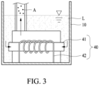
- FIG. 3 is a cross-sectional diagram of a cartridge of FIG. 1 according to an embodiment
- FIG. 4 is a diagram illustrating a housing provided with a touch sensor, according to an embodiment
- FIG. 5 is a diagram illustrating the operation principle of a touch sensor according to an embodiment.
- an aerosol generating device 1 using capacitive touch sensing may include a housing 10, an aerosol outlet 30, a cartridge 20, a heater 40, a controller 50, and a touch sensor 60.
- the housing 10 may form the exterior of the aerosol generating device 1 using capacitive touch sensing.
- a battery B may be provided in the inner space, and although not shown in the drawing, a circuit board (not shown) with an electronic chip (not shown) may be provided.
- a light emitting diode (not shown) that lights up according to an inhaling action or a display unit (not shown) that displays inhalation information may be provided.
- a rechargeable polymer lithium battery, a lithium ion battery, or the like may be used as the battery B.
- the aerosol outlet 30 may be provided in the housing 10 and may have one side exposed to the outside.
- the other side of the aerosol outlet 30 may be connected to the cartridge 20 that is described below and may discharge an aerosol A generated from the cartridge 20 to the outside.
- the aerosol outlet 30 may have a straw shape protruding from one side of the cartridge 20 but is not necessarily limited thereto.
- an opening portion of a gourd shape, a cylindrical shape, a hole shape, and the like may be included.
- the material of the opening portion may be made of various materials such as plastic synthetic resin, stainless steel, glass, Teflon, rubber, and the like.
- the cartridge 20 may be provided in the housing 10 and may store an aerosol forming substrate L.
- the "aerosol forming substrate L" may refer to a material capable of forming the aerosol A.
- the aerosol A may include a volatile compound.
- the aerosol forming substrate L may be solid or liquid.
- a solid aerosol forming substrate L may include solid materials based on tobacco raw materials such as tobacco sheets, cut tobacco leaves, reconstituted tobacco, and the like, and a liquid aerosol forming substrate L may include a liquid composition based on nicotine, a tobacco extract, and/or various flavoring agents.
- the scope of the present embodiment is not limited thereto.
- the heater 40 may be disposed in the cartridge 20 and may heat the cartridge 20 to generate the aerosol A.
- the heater 40 may include a wick 41 and a heating coil 42.
- the wick 41 may include at least one of cotton fiber, ceramic fiber, glass fiber, or porous ceramic, or a compound thereof, but is not limited thereto.
- the heating coil 42 may be disposed in a form of winding the wick 41, which may be connected to the controller 50 that is described below to generate heat, thereby heating the wick 41.
- the aerosol A may be generated from the aerosol forming substrate L stored in the cartridge 20.
- the controller 50 may control the operation of the heater 40. In addition, the controller 50 may control the overall operation of the aerosol generating device 1 using capacitive touch sensing. In an embodiment, the controller 50 may include at least one processor.
- the processor may be implemented as an array of a plurality of logic gates or may be implemented as a combination of a general-purpose microprocessor and a memory 51 in which a program executable by the microprocessor is stored.
- the processor may be implemented in other types of hardware.
- the controller 50 may control the temperature of the heater 40 by controlling the supply of power to the heater 40.
- the controller 50 may control the supply of power to the heater 40 by controlling switching of a switching element between the battery B and the heater 40.
- a direct heating circuit may control the supply of power to the heater 40 according to a control command from the controller 50.
- the touch sensor 60 may be provided in the outer circumferential surface of the housing 10.
- the touch sensor 60 may be provided in at least one outer circumferential surface of the housing 10.
- the housing 10 may include an end portion surface 11 in which the aerosol outlet 30 may be disposed, a first side surface 12 perpendicular to the aerosol outlet 30, and a second side surface 13 that is perpendicular to the aerosol outlet 30 and is on the opposite side to the first side surface 12.
- the touch sensor 60 may include a first touch sensor 61 disposed on the first side surface 12 and a second touch sensor 62 disposed on the second side surface 13.
- the touch sensor 60 may be configured as a capacitive sensor.
- the capacitive sensor is a sensor that operates by detecting a change in electrical capacity/capacitance, which occurs when a body part or a specific object is in contact with the capacitive sensor.
- the touch sensor 60 may have an electrical capacity/capacitance value of a predetermined size when a body part or a specific object is not in contact and may have the same effect as when touch sensors (e.g., the touch sensor 60) are connected in parallel when a body part or a specific object is in contact. That is, when a body part or a specific object contacts the touch sensor 60, the electrical capacity/capacitance value may increase, and a variation in an electrical capacity/capacitance may be transmitted to the controller 50.
- the capacitance of the touch sensor 60 may increase when the contact area increases, and the controller 50 may calculate the variation in the capacitance and apply a power value to the heater 40.
- the touch sensor 60 may transmit contact area information to the controller 50, and the controller 50 may adjust the power value applied to the heater 40 based on the contact area information.
- the aerosol generating device 1 using capacitive touch sensing may further include a puff sensor 70.
- puff refers to inhalation by a user, and inhalation refers to a situation in which a user draws in an aerosol into their oral cavity, nasal cavity, or lungs through the mouth or nose.
- the puff sensor 70 may detect the intensity of the puff and transmit the intensity of the puff to the controller 50.
- the puff sensor 70 may detect a puff by a user based on various physical changes in an airflow path or airflow channel.
- the puff sensor 70 may detect the puff by the user based on one of a temperature change, a flow change, a voltage change, and a pressure change.
- the puff sensor 70 may be provided in the aerosol outlet 30 to detect puffs but is not necessarily limited thereto.
- the controller 50 may further include a memory 51, and the memory 51 may store a current value at the time of a previous puff.
- the memory 51 which is hardware for storing various pieces of data processed by the aerosol generating device 1 using capacitive touch sensing, may store data processed by the controller 50 and data to be processed thereby.
- the memory 51 may include at least one type of storage medium of flash memory type memory, hard disk type memory, multimedia card micro type memory, card type memory (e.g., an SD or xD memory), random access memory (RAM), static random-access memory (SRAM), read-only memory (ROM), electrically erasable programmable read-only memory (EEPROM), programmable read-only memory (PROM), magnetic memory, a magnetic disk, or an optical disk.
- flash memory type memory e.g., hard disk type memory, multimedia card micro type memory, card type memory (e.g., an SD or xD memory), random access memory (RAM), static random-access memory (SRAM), read-only memory (ROM), electrically erasable programmable read-only memory (EEPROM), programmable read-only memory (PROM), magnetic memory, a magnetic disk, or an optical disk.
- the memory 51 may store a current value at the time of a previous puff that is applied to the heater 40 by the controller 50 to generate reference information for determining a current value at the time of a subsequent puff.
- the memory 51 may store an operating time of the aerosol generating device 1 using capacitive touch sensing, the maximum number of puffs, the current number of puffs, at least one temperature profile, data associated with a smoking pattern of the user, or the like.
- the controller 50 may generate a compensation current value by comparing contact area information transmitted from the touch sensor 60 at the time of a previous puff to contact area information transmitted from the touch sensor 60 at the time of a current puff and add or subtract the compensation current value to or from the current value at the time of the previous puff. That is, the controller 50 may add or subtract the variation in the contact area information transmitted from the touch sensor 60 to or from the current value at the time of the previous puff that is applied to the heater 40 by the controller 50 and that is stored in the memory 51 and may supply power to the heater 40, thereby adjusting the amount of aerosol generation according to the user's touch intensity and the like.
- the controller 50 may adjust the power value applied to the heater 40 according to the following equation.
- P nPuff V BAT I n ⁇ 1 Puff + I ⁇ C
- P nPuff may be a power value at the time of the current puff
- V BAT may be a voltage value applied from a battery
- I (n-1Puff) may be the current value at the time of the previous puff
- I ⁇ C may be the compensation current value.
- the controller 50 may store the current value I (n-1Puff) at the time of the previous puff in the memory 51, add or subtract the compensation current value I ⁇ C derived by comparing the contact area information transmitted from the touch sensor 60 at the time of the previous puff to the contact area information transmitted from the touch sensor 60 at the time of the current puff to or from the current value I(n-1Puff) at the time of the previous puff, and apply the current value to the heater 40.
- the compensation current value I ⁇ C may be derived according to the increased contact area and added to the current value I(n-1Puff) at the time of the previous puff, and the current value may be applied to the heater 40.
- the power value (PnPuff) applied to the heater 40 may be increased compared to the previous puff and accordingly, the amount of atomization may be increased.
- the controller 50 may add or subtract the compensation current value I ⁇ C to or from the current value I(n-1Puff) at the time of the previous puff and apply the current value to the heater 40, and thus, the power value PnPuff at the time of the current puff may be adjusted and the amount of aerosol generation may be adjusted.
- the aerosol generating device 1 using capacitive touch sensing may include a touch sensor interlocked with a controller to adjust the amount of atomization according to a user's preference.
- the aerosol generating device 1 using capacitive touch sensing may have the advantage of being easy and simple to operate because the amount of atomization may be adjusted through the change in the contact area of the touch sensor.
Landscapes
- Engineering & Computer Science (AREA)
- Human Computer Interaction (AREA)
- Power Engineering (AREA)
- Disinfection, Sterilisation Or Deodorisation Of Air (AREA)
- Switches That Are Operated By Magnetic Or Electric Fields (AREA)
- Infusion, Injection, And Reservoir Apparatuses (AREA)
Abstract
Description
- The embodiments below relate to an aerosol generating device using capacitive touch sensing.
- Recently, demands for alternative ways to overcome disadvantages of general cigarettes have increased. For example, there is a growing demand for a device for generating an aerosol by heating an aerosol generating material rather than using a method of generating an aerosol by burning a cigarette. Accordingly, research on a heating-type aerosol generating device is being actively conducted. A conventional heating-type aerosol generating device has limitations in that the aerosol generated to prevent carbonization of the cartridge wick stays constant or increases even when a smoker wants a larger amount of atomization. Therefore, it is necessary to develop an aerosol generating device capable of adjusting the amount of atomization according to an aerosol smoker's preference. For example,
Korean Patent Publication No. 10-2013-0036585 - The above description has been possessed or acquired by the inventor(s) in the course of conceiving the present disclosure and is not necessarily an art publicly known before the present application is filed.
- An aspect of the embodiments is to provide an aerosol generating device using capacitive touch sensing for which a smoker may adjust the amount of atomization.
- The technical goals obtainable from the embodiments are not limited to the above-mentioned technical goals, and other unmentioned technical goals may be clearly understood from the following description by one of ordinary skill in the art to which the present disclosure pertains. Technical Solutions
- An aerosol generating device using capacitive touch sensing according to the embodiments is disclosed. The aerosol generating device using capacitive touch sensing includes a housing, an aerosol outlet provided in the housing and having one side exposed to the outside, a cartridge provided in the housing and configured to store an aerosol generating substrate, a heater provided in the housing and configured to generate an aerosol by heating the cartridge, a controller configured to control an operation of the heater, and a touch sensor provided in an outer circumferential surface of the housing, wherein the touch sensor is configured to transmit contact area information to the controller, and the controller is configured to adjust a power value applied to the heater based on the contact area information.
- According to an aspect, the touch sensor may include a capacitive sensor.
- According to an aspect, capacitance of the touch sensor may increase when a contact area increases, and the controller may be configured to calculate a variation in a capacitance and apply the power value to the heater.
- According to an aspect, the aerosol generating device using capacitive touch sensing may further include a puff sensor configured to detect an intensity of a puff and transmit the intensity to the controller.
- According to an aspect, the controller may further include a memory, and the memory may be configured to store a current value at the time of a previous puff.
- According to an aspect, the controller may be configured to generate a compensation current value by comparing contact area information transmitted from the touch sensor at the time of a previous puff to contact area information transmitted from the touch sensor at the time of a current puff and add or subtract the compensation current value to or from the current value at the time of the previous puff.
- According to an aspect, the controller may be configured to adjust the power value applied to the heater based on the following equation PnPuff=VBAT(I(n-1Puff)+IΔC), wherein PnPuff may denote a power value at the time of the current puff, VBAT may denote a voltage value applied from a battery, I(n-1Puff) may denote the current value at the time of the previous puff, and IΔC may denote the compensation current value.
- According to an aspect, the touch sensor may be provided in at least one outer circumferential surface of the housing.
- According to an aspect, the housing may include an end portion surface in which the aerosol outlet is disposed, a first side perpendicular to the aerosol outlet, and a second side perpendicular to the aerosol outlet and opposite to the first side, and the touch sensor may include a first touch sensor disposed on the first side and a second touch sensor disposed on the second side.
- As described above, according to embodiments, an aerosol generating device using capacitive touch sensing may include a touch sensor so that a smoker may easily adjust the amount of atomization by changing a contact area of the touch sensor.
- The effects of the aerosol generating device using capacitive touch sensing according to an embodiment are not limited to the above-mentioned effects, and other unmentioned effects can be clearly understood from the following description by one of ordinary skill in the art.
-
-
FIG. 1 is a diagram illustrating a cross section of an aerosol generating device using capacitive touch sensing, according to an embodiment. -
FIG. 2 is a block diagram illustrating an aerosol generating device using capacitive touch sensing, according to an embodiment. -
FIG. 3 is a diagram illustrating a cross section of a cartridge ofFIG. 1 according to an embodiment. -
FIG. 4 is a diagram illustrating a housing provided with a touch sensor, according to an embodiment. -
FIG. 5 is a diagram illustrating the operation principle of a touch sensor according to an embodiment. - Hereinafter, embodiments will be described in detail with reference to the accompanying drawings. However, various alterations and modifications may be made to the embodiments. Here, the embodiments are not meant to be limited by the descriptions of the present disclosure. The embodiments should be understood to include all changes, equivalents, and replacements within the idea and the technical scope of the disclosure.
- The terminology used herein is for the purpose of describing particular embodiments only and is not intended to be limiting. The singular forms "a", "an", and "the" are intended to include the plural forms as well, unless the context clearly indicates otherwise. It will be further understood that the terms "comprises/comprising" and/or "includes/including" when used herein, specify the presence of stated features, integers, steps, operations, elements, and/or components, but do not preclude the presence or addition of one or more other features, integers, steps, operations, elements, components and/or groups thereof.
- Unless otherwise defined, all terms including technical and scientific terms used herein have the same meaning as commonly understood by one of ordinary skill in the art to which the embodiments belong. Terms, such as those defined in commonly used dictionaries, are to be interpreted as having a meaning that is consistent with their meaning in the context of the relevant art and the present disclosure, and are not to be interpreted in an idealized or overly formal sense unless expressly so defined herein.
- When describing the embodiments with reference to the accompanying drawings, like reference numerals refer to like components and a repeated description related thereto will be omitted. In the description of embodiments, detailed description of well-known related structures or functions will be omitted when it is deemed that such description will cause ambiguous interpretation of the present disclosure.
- In addition, terms such as first, second, A, B, (a), (b), and the like may be used to describe components of the embodiments. These terms are used only for the purpose of discriminating one component from another component, and the nature, the sequences, or the orders of the components are not limited by the terms. It should be noted that if one component is described as being "connected", "coupled" or "joined" to another component, the former may be directly "connected," "coupled", and "joined" to the latter or "connected", "coupled", and "joined" to the latter via another component.
- A component, which has the same common function as a component included in any one embodiment, will be described by using the same name in other embodiments. Unless disclosed to the contrary, the configuration disclosed in any one embodiment may be applied to other embodiments, and the specific description of the repeated configuration will be omitted.
- An aerosol generating device using capacitive touch sensing will be described with reference to the drawings. For reference,
FIG. 1 is a cross-sectional diagram of an aerosol generating device using capacitive touch sensing, according to an embodiment,FIG. 2 is a block diagram illustrating an aerosol generating device using capacitive touch sensing, according to an embodiment,FIG. 3 is a cross-sectional diagram of a cartridge ofFIG. 1 according to an embodiment,FIG. 4 is a diagram illustrating a housing provided with a touch sensor, according to an embodiment, andFIG. 5 is a diagram illustrating the operation principle of a touch sensor according to an embodiment. - Referring to
FIG. 1 to 4 , anaerosol generating device 1 using capacitive touch sensing according to an embodiment may include ahousing 10, anaerosol outlet 30, acartridge 20, aheater 40, acontroller 50, and atouch sensor 60. - The
housing 10 according to an embodiment may form the exterior of theaerosol generating device 1 using capacitive touch sensing. In thehousing 10, a battery B may be provided in the inner space, and although not shown in the drawing, a circuit board (not shown) with an electronic chip (not shown) may be provided. On the front end portion of thehousing 10, a light emitting diode (not shown) that lights up according to an inhaling action or a display unit (not shown) that displays inhalation information may be provided. Here, a rechargeable polymer lithium battery, a lithium ion battery, or the like may be used as the battery B. - The
aerosol outlet 30 according to an embodiment may be provided in thehousing 10 and may have one side exposed to the outside. The other side of theaerosol outlet 30 may be connected to thecartridge 20 that is described below and may discharge an aerosol A generated from thecartridge 20 to the outside. For example, theaerosol outlet 30 may have a straw shape protruding from one side of thecartridge 20 but is not necessarily limited thereto. In addition, an opening portion of a gourd shape, a cylindrical shape, a hole shape, and the like may be included. In addition, the material of the opening portion may be made of various materials such as plastic synthetic resin, stainless steel, glass, Teflon, rubber, and the like. - Referring to
FIG 2 , thecartridge 20 according to an embodiment may be provided in thehousing 10 and may store an aerosol forming substrate L. Here, the "aerosol forming substrate L" may refer to a material capable of forming the aerosol A. The aerosol A may include a volatile compound. The aerosol forming substrate L may be solid or liquid. For example, a solid aerosol forming substrate L may include solid materials based on tobacco raw materials such as tobacco sheets, cut tobacco leaves, reconstituted tobacco, and the like, and a liquid aerosol forming substrate L may include a liquid composition based on nicotine, a tobacco extract, and/or various flavoring agents. However, the scope of the present embodiment is not limited thereto. - The
heater 40 according to an embodiment may be disposed in thecartridge 20 and may heat thecartridge 20 to generate the aerosol A. Theheater 40 may include awick 41 and aheating coil 42. Thewick 41 may include at least one of cotton fiber, ceramic fiber, glass fiber, or porous ceramic, or a compound thereof, but is not limited thereto. Theheating coil 42 may be disposed in a form of winding thewick 41, which may be connected to thecontroller 50 that is described below to generate heat, thereby heating thewick 41. By theheated wick 41, the aerosol A may be generated from the aerosol forming substrate L stored in thecartridge 20. - The
controller 50 according to an embodiment may control the operation of theheater 40. In addition, thecontroller 50 may control the overall operation of theaerosol generating device 1 using capacitive touch sensing. In an embodiment, thecontroller 50 may include at least one processor. The processor may be implemented as an array of a plurality of logic gates or may be implemented as a combination of a general-purpose microprocessor and amemory 51 in which a program executable by the microprocessor is stored. In addition, it is to be understood by one of ordinary skill in the art to which the present disclosure pertains that the processor may be implemented in other types of hardware. - The
controller 50 according to an embodiment may control the temperature of theheater 40 by controlling the supply of power to theheater 40. For example, thecontroller 50 may control the supply of power to theheater 40 by controlling switching of a switching element between the battery B and theheater 40. In another example, a direct heating circuit may control the supply of power to theheater 40 according to a control command from thecontroller 50. - Referring to
FIG. 4 , thetouch sensor 60 according to an embodiment may be provided in the outer circumferential surface of thehousing 10. Thetouch sensor 60 may be provided in at least one outer circumferential surface of thehousing 10. For example, thehousing 10 may include anend portion surface 11 in which theaerosol outlet 30 may be disposed, afirst side surface 12 perpendicular to theaerosol outlet 30, and asecond side surface 13 that is perpendicular to theaerosol outlet 30 and is on the opposite side to thefirst side surface 12. Thetouch sensor 60 may include afirst touch sensor 61 disposed on thefirst side surface 12 and asecond touch sensor 62 disposed on thesecond side surface 13. - Referring to
FIG. 5 , thetouch sensor 60 according to an embodiment may be configured as a capacitive sensor. The capacitive sensor is a sensor that operates by detecting a change in electrical capacity/capacitance, which occurs when a body part or a specific object is in contact with the capacitive sensor. Thetouch sensor 60 may have an electrical capacity/capacitance value of a predetermined size when a body part or a specific object is not in contact and may have the same effect as when touch sensors (e.g., the touch sensor 60) are connected in parallel when a body part or a specific object is in contact. That is, when a body part or a specific object contacts thetouch sensor 60, the electrical capacity/capacitance value may increase, and a variation in an electrical capacity/capacitance may be transmitted to thecontroller 50. - Here, the capacitance of the
touch sensor 60 according to an embodiment may increase when the contact area increases, and thecontroller 50 may calculate the variation in the capacitance and apply a power value to theheater 40. Thetouch sensor 60 may transmit contact area information to thecontroller 50, and thecontroller 50 may adjust the power value applied to theheater 40 based on the contact area information. - In addition, the
aerosol generating device 1 using capacitive touch sensing according to an embodiment may further include apuff sensor 70. In the following embodiments, the term "puff" refers to inhalation by a user, and inhalation refers to a situation in which a user draws in an aerosol into their oral cavity, nasal cavity, or lungs through the mouth or nose. - The
puff sensor 70 according to an embodiment may detect the intensity of the puff and transmit the intensity of the puff to thecontroller 50. Thepuff sensor 70 may detect a puff by a user based on various physical changes in an airflow path or airflow channel. For example, thepuff sensor 70 may detect the puff by the user based on one of a temperature change, a flow change, a voltage change, and a pressure change. Thepuff sensor 70 may be provided in theaerosol outlet 30 to detect puffs but is not necessarily limited thereto. - Here, the
controller 50 according to an embodiment may further include amemory 51, and thememory 51 may store a current value at the time of a previous puff. Here, thememory 51, which is hardware for storing various pieces of data processed by theaerosol generating device 1 using capacitive touch sensing, may store data processed by thecontroller 50 and data to be processed thereby. Thememory 51 may include at least one type of storage medium of flash memory type memory, hard disk type memory, multimedia card micro type memory, card type memory (e.g., an SD or xD memory), random access memory (RAM), static random-access memory (SRAM), read-only memory (ROM), electrically erasable programmable read-only memory (EEPROM), programmable read-only memory (PROM), magnetic memory, a magnetic disk, or an optical disk. - The
memory 51 according to an embodiment may store a current value at the time of a previous puff that is applied to theheater 40 by thecontroller 50 to generate reference information for determining a current value at the time of a subsequent puff. - In addition, the
memory 51 may store an operating time of theaerosol generating device 1 using capacitive touch sensing, the maximum number of puffs, the current number of puffs, at least one temperature profile, data associated with a smoking pattern of the user, or the like. - Here, the
controller 50 may generate a compensation current value by comparing contact area information transmitted from thetouch sensor 60 at the time of a previous puff to contact area information transmitted from thetouch sensor 60 at the time of a current puff and add or subtract the compensation current value to or from the current value at the time of the previous puff. That is, thecontroller 50 may add or subtract the variation in the contact area information transmitted from thetouch sensor 60 to or from the current value at the time of the previous puff that is applied to theheater 40 by thecontroller 50 and that is stored in thememory 51 and may supply power to theheater 40, thereby adjusting the amount of aerosol generation according to the user's touch intensity and the like. - According to the configuration described above, the
controller 50 according to an embodiment may adjust the power value applied to theheater 40 according to the following equation.
- Here, PnPuff may be a power value at the time of the current puff, VBAT may be a voltage value applied from a battery, I(n-1Puff) may be the current value at the time of the previous puff, and IΔC may be the compensation current value. The
controller 50 may store the current value I(n-1Puff) at the time of the previous puff in thememory 51, add or subtract the compensation current value IΔC derived by comparing the contact area information transmitted from thetouch sensor 60 at the time of the previous puff to the contact area information transmitted from thetouch sensor 60 at the time of the current puff to or from the current value I(n-1Puff) at the time of the previous puff, and apply the current value to theheater 40. For example, if the contact area increases at the time of the current puff than at the time of the previous puff, the compensation current value IΔC may be derived according to the increased contact area and added to the current value I(n-1Puff) at the time of the previous puff, and the current value may be applied to theheater 40. In this case, the power value (PnPuff) applied to theheater 40 may be increased compared to the previous puff and accordingly, the amount of atomization may be increased. That is, thecontroller 50 according to an embodiment may add or subtract the compensation current value IΔC to or from the current value I(n-1Puff) at the time of the previous puff and apply the current value to theheater 40, and thus, the power value PnPuff at the time of the current puff may be adjusted and the amount of aerosol generation may be adjusted. - According to embodiments, the
aerosol generating device 1 using capacitive touch sensing may include a touch sensor interlocked with a controller to adjust the amount of atomization according to a user's preference. - In addition, the
aerosol generating device 1 using capacitive touch sensing may have the advantage of being easy and simple to operate because the amount of atomization may be adjusted through the change in the contact area of the touch sensor. - The descriptions of the above-described embodiments are only examples, and it will be understood by one of ordinary skill in the art that various changes and equivalents may be made thereto. Therefore, the scope of the disclosure should be defined by the appended claims, and all differences within the scope equivalent to those described in the claims will be construed as being included in the scope of protection defined by the claims.
- The features and aspects of any embodiment(s) described above may be combined with features and aspects of any other embodiment(s) without resulting in apparent technical conflicts.
Claims (9)
- An aerosol generating device using capacitive touch sensing, the aerosol generating device comprising:a housing;an aerosol outlet provided in the housing and having one side exposed to the outside;a cartridge provided in the housing and configured to store an aerosol generating substrate;a heater provided in the housing and configured to generate an aerosol by heating the cartridge;a controller configured to control an operation of the heater; anda touch sensor provided in an outer circumferential surface of the housing,wherein the touch sensor is configured to transmit contact area information to the controller, and the controller is configured to adjust a power value applied to the heater based on the contact area information.
- The aerosol generating device of claim 1, wherein the touch sensor comprises a capacitive sensor.
- The aerosol generating device of claim 2, wherein capacitance of the touch sensor increases when a contact area increases, and the controller is configured to calculate a variation in a capacitance and apply the power value to the heater.
- The aerosol generating device of claim 1, further comprising a puff sensor configured to detect an intensity of a puff and transmit the intensity to the controller.
- The aerosol generating device of claim 4, wherein the controller further comprises a memory, and the memory is configured to store a current value at the time of a previous puff.
- The aerosol generating device of claim 5, wherein the controller is configured to generate a compensation current value by comparing contact area information transmitted from the touch sensor at the time of a previous puff to contact area information transmitted from the touch sensor at the time of a current puff and add or subtract the compensation current value to or from the current value at the time of the previous puff.
- The aerosol generating device of claim 6, wherein the controller is configured to adjust the power value applied to the heater based on the following equation:

- The aerosol generating device of claim 1, wherein the touch sensor is provided in at least one outer circumferential surface of the housing.
- The aerosol generating device of claim 8, wherein
the housing comprises:an end portion surface in which the aerosol outlet is disposed;a first side perpendicular to the aerosol outlet; anda second side perpendicular to the aerosol outlet and opposite to the first side, and the touch sensor comprises:a first touch sensor disposed on the first side; anda second touch sensor disposed on the second side.
Applications Claiming Priority (2)
| Application Number | Priority Date | Filing Date | Title |
|---|---|---|---|
| KR1020220074862A KR102800079B1 (en) | 2022-06-20 | 2022-06-20 | Aerosol-generating device using capacitive touch sensing |
| PCT/KR2023/002896 WO2023249202A1 (en) | 2022-06-20 | 2023-03-03 | Aerosol generating device using capacitive touch sensing |
Publications (2)
| Publication Number | Publication Date |
|---|---|
| EP4327679A1 true EP4327679A1 (en) | 2024-02-28 |
| EP4327679A4 EP4327679A4 (en) | 2024-10-30 |
Family
ID=88833983
Family Applications (1)
| Application Number | Title | Priority Date | Filing Date |
|---|---|---|---|
| EP23801286.8A Pending EP4327679A4 (en) | 2022-06-20 | 2023-03-03 | AEROSOL GENERATING DEVICE USING CAPACITIVE TOUCH SENSING |
Country Status (6)
| Country | Link |
|---|---|
| US (1) | US20250160435A1 (en) |
| EP (1) | EP4327679A4 (en) |
| JP (1) | JP7556499B2 (en) |
| KR (1) | KR102800079B1 (en) |
| CN (1) | CN117693299A (en) |
| WO (1) | WO2023249202A1 (en) |
Families Citing this family (1)
| Publication number | Priority date | Publication date | Assignee | Title |
|---|---|---|---|---|
| CN118077979A (en) * | 2024-04-11 | 2024-05-28 | 爱奇迹创造有限公司 | Atomizer, atomizing device, control method and device, controller, storage medium |
Family Cites Families (16)
| Publication number | Priority date | Publication date | Assignee | Title |
|---|---|---|---|---|
| KR100273362B1 (en) * | 1997-06-11 | 2001-01-15 | 구자홍 | Automatic volume correction method and apparatus |
| KR20110033488A (en) * | 2009-09-25 | 2011-03-31 | 엘지전자 주식회사 | Input device with touch sensor |
| US9820008B2 (en) * | 2010-08-27 | 2017-11-14 | Intel Corporation | Capture and recall of home entertainment system session |
| KR101312195B1 (en) | 2011-10-04 | 2013-09-27 | 주식회사 케이티앤지 | Apparatus to inhale aerosol |
| US9811220B2 (en) * | 2015-06-19 | 2017-11-07 | NXA USA, Inc. | Signal adaptive filtering for touch detection |
| JP6676906B2 (en) * | 2015-09-16 | 2020-04-08 | カシオ計算機株式会社 | Electronic musical instrument lead and electronic musical instrument |
| US10206431B2 (en) * | 2016-11-18 | 2019-02-19 | Rai Strategic Holdings, Inc. | Charger for an aerosol delivery device |
| KR102692984B1 (en) * | 2017-02-06 | 2024-08-08 | 삼성전자주식회사 | Touch input processing method and electronic device supporting the same |
| KR102326001B1 (en) * | 2019-07-24 | 2021-11-12 | 주식회사 케이티앤지 | Cartridge and Aerosol generating device including the same |
| KR102278593B1 (en) * | 2019-07-29 | 2021-07-16 | 주식회사 케이티앤지 | Aerosol generating device and operation method thereof |
| WO2021032668A1 (en) * | 2019-08-21 | 2021-02-25 | Philip Morris Products S.A. | An aerosol-generating system and an interface element for an aerosol-generating system |
| KR20210039199A (en) * | 2019-10-01 | 2021-04-09 | 주식회사 케이티앤지 | Aerosol generating device including display |
| KR102299647B1 (en) * | 2019-12-24 | 2021-09-08 | 주식회사 이엠텍 | Driving device and driving method of portable aerosol generator |
| KR102295618B1 (en) * | 2020-02-07 | 2021-08-30 | 주식회사 케이티앤지 | Aerosol generating device for determining puff number and operation method thereof |
| KR102432917B1 (en) * | 2020-03-30 | 2022-08-16 | 주식회사 케이티앤지 | Aerosol generating device that activates heater by detecting user's contact and method for operating the same |
| GB202009486D0 (en) * | 2020-06-22 | 2020-08-05 | Nicoventures Holdings Ltd | User feedback system and method |
-
2022
- 2022-06-20 KR KR1020220074862A patent/KR102800079B1/en active Active
-
2023
- 2023-03-03 CN CN202380011797.2A patent/CN117693299A/en active Pending
- 2023-03-03 EP EP23801286.8A patent/EP4327679A4/en active Pending
- 2023-03-03 US US18/290,245 patent/US20250160435A1/en active Pending
- 2023-03-03 WO PCT/KR2023/002896 patent/WO2023249202A1/en not_active Ceased
- 2023-03-03 JP JP2023542737A patent/JP7556499B2/en active Active
Also Published As
| Publication number | Publication date |
|---|---|
| US20250160435A1 (en) | 2025-05-22 |
| CN117693299A (en) | 2024-03-12 |
| JP7556499B2 (en) | 2024-09-26 |
| JP2024527660A (en) | 2024-07-26 |
| WO2023249202A1 (en) | 2023-12-28 |
| KR20230173976A (en) | 2023-12-27 |
| KR102800079B1 (en) | 2025-04-28 |
| EP4327679A4 (en) | 2024-10-30 |
Similar Documents
| Publication | Publication Date | Title |
|---|---|---|
| US12317933B2 (en) | Variable power control electronic vaping device | |
| US12274309B2 (en) | Burning prediction and communications for an electronic cigarette | |
| RU2689514C1 (en) | Electronic device for steam production | |
| EP3406147B1 (en) | Non-combustible flavor inhaler, method, program and storage medium | |
| KR102330286B1 (en) | Aerosol-generating device and method for controlling the same | |
| KR102199792B1 (en) | Heating type fine particle generator | |
| US10750782B2 (en) | Aerosol-generating system comprising cartridge detection | |
| JP2020521438A (en) | Apparatus and method for producing aerosol having cigarette insertion sensing function | |
| KR102295618B1 (en) | Aerosol generating device for determining puff number and operation method thereof | |
| KR20190033531A (en) | Heater management | |
| CN114766739A (en) | Aerosol generating device and method providing adaptive feedback based on puff identification | |
| EP4327679A1 (en) | Aerosol generating device using capacitive touch sensing | |
| KR102278592B1 (en) | Aerosol Generating Device and OPERATION METHOD THEREOF | |
| CN114355042B (en) | Resistance detection system and method | |
| CN114173589A (en) | Aerosol-generating system and interface element for an aerosol-generating system | |
| CN116261405A (en) | Aerosol generating device for controlling power supplied to heater and method of operation thereof | |
| EP4203728A1 (en) | Article for an aerosol provision system | |
| KR102460980B1 (en) | Liquid cartridge and aerosol-generating apparatus including the same | |
| US20240268473A1 (en) | Aerosol generating device and operating method therefor | |
| EP4659605A1 (en) | Aerosol-generating device and aerosol-generating system comprising same | |
| JP7666794B2 (en) | Aerosol-generating medium manufacturing system, aerosol-generating article manufacturing method, and aerosol-generating article | |
| EP4616740A1 (en) | Non-combustion-type flavor inhaler | |
| KR20250104311A (en) | Aerosol generating device comprising a sensor module | |
| KR20240121130A (en) | Aerosol generating apparatus and aerosol generating system including the same |
Legal Events
| Date | Code | Title | Description |
|---|---|---|---|
| STAA | Information on the status of an ep patent application or granted ep patent |
Free format text: STATUS: UNKNOWN |
|
| STAA | Information on the status of an ep patent application or granted ep patent |
Free format text: STATUS: THE INTERNATIONAL PUBLICATION HAS BEEN MADE |
|
| PUAI | Public reference made under article 153(3) epc to a published international application that has entered the european phase |
Free format text: ORIGINAL CODE: 0009012 |
|
| STAA | Information on the status of an ep patent application or granted ep patent |
Free format text: STATUS: REQUEST FOR EXAMINATION WAS MADE |
|
| 17P | Request for examination filed |
Effective date: 20231115 |
|
| AK | Designated contracting states |
Kind code of ref document: A1 Designated state(s): AL AT BE BG CH CY CZ DE DK EE ES FI FR GB GR HR HU IE IS IT LI LT LU LV MC ME MK MT NL NO PL PT RO RS SE SI SK SM TR |
|
| REG | Reference to a national code |
Ref country code: DE Ref legal event code: R079 Free format text: PREVIOUS MAIN CLASS: A24F0040500000 Ipc: A24F0040600000 |
|
| A4 | Supplementary search report drawn up and despatched |
Effective date: 20240926 |
|
| RIC1 | Information provided on ipc code assigned before grant |
Ipc: A24F 40/10 20200101ALN20240920BHEP Ipc: A24F 40/50 20200101ALN20240920BHEP Ipc: H02J 7/00 20060101ALI20240920BHEP Ipc: A24F 40/46 20200101ALI20240920BHEP Ipc: A24F 40/485 20200101ALI20240920BHEP Ipc: A24F 40/42 20200101ALI20240920BHEP Ipc: A24F 40/51 20200101ALI20240920BHEP Ipc: A24F 40/60 20200101AFI20240920BHEP |
|
| DAV | Request for validation of the european patent (deleted) | ||
| DAX | Request for extension of the european patent (deleted) | ||
| STAA | Information on the status of an ep patent application or granted ep patent |
Free format text: STATUS: EXAMINATION IS IN PROGRESS |
|
| 17Q | First examination report despatched |
Effective date: 20260120 |
|
| RIC1 | Information provided on ipc code assigned before grant |
Ipc: A24F 40/60 20200101AFI20260115BHEP Ipc: A24F 40/51 20200101ALI20260115BHEP Ipc: A24F 40/42 20200101ALI20260115BHEP Ipc: A24F 40/485 20200101ALI20260115BHEP Ipc: A24F 40/46 20200101ALI20260115BHEP Ipc: H02J 7/00 20060101ALI20260115BHEP Ipc: A24F 40/50 20200101ALN20260115BHEP Ipc: A24F 40/10 20200101ALN20260115BHEP |