EP4326981B1 - Internal combustion engine - Google Patents
Internal combustion engine Download PDFInfo
- Publication number
- EP4326981B1 EP4326981B1 EP21721820.5A EP21721820A EP4326981B1 EP 4326981 B1 EP4326981 B1 EP 4326981B1 EP 21721820 A EP21721820 A EP 21721820A EP 4326981 B1 EP4326981 B1 EP 4326981B1
- Authority
- EP
- European Patent Office
- Prior art keywords
- engine
- ammonia
- prechamber
- piston
- hydrogen
- Prior art date
- Legal status (The legal status is an assumption and is not a legal conclusion. Google has not performed a legal analysis and makes no representation as to the accuracy of the status listed.)
- Active
Links
Images
Classifications
-
- F—MECHANICAL ENGINEERING; LIGHTING; HEATING; WEAPONS; BLASTING
- F02—COMBUSTION ENGINES; HOT-GAS OR COMBUSTION-PRODUCT ENGINE PLANTS
- F02D—CONTROLLING COMBUSTION ENGINES
- F02D41/00—Electrical control of supply of combustible mixture or its constituents
- F02D41/0025—Controlling engines characterised by use of non-liquid fuels, pluralities of fuels, or non-fuel substances added to the combustible mixtures
- F02D41/0027—Controlling engines characterised by use of non-liquid fuels, pluralities of fuels, or non-fuel substances added to the combustible mixtures the fuel being gaseous
-
- F—MECHANICAL ENGINEERING; LIGHTING; HEATING; WEAPONS; BLASTING
- F02—COMBUSTION ENGINES; HOT-GAS OR COMBUSTION-PRODUCT ENGINE PLANTS
- F02B—INTERNAL-COMBUSTION PISTON ENGINES; COMBUSTION ENGINES IN GENERAL
- F02B19/00—Engines characterised by precombustion chambers
- F02B19/10—Engines characterised by precombustion chambers with fuel introduced partly into pre-combustion chamber, and partly into cylinder
- F02B19/1019—Engines characterised by precombustion chambers with fuel introduced partly into pre-combustion chamber, and partly into cylinder with only one pre-combustion chamber
- F02B19/1023—Engines characterised by precombustion chambers with fuel introduced partly into pre-combustion chamber, and partly into cylinder with only one pre-combustion chamber pre-combustion chamber and cylinder being fed with fuel-air mixture(s)
- F02B19/1028—Engines characterised by precombustion chambers with fuel introduced partly into pre-combustion chamber, and partly into cylinder with only one pre-combustion chamber pre-combustion chamber and cylinder being fed with fuel-air mixture(s) pre-combustion chamber and cylinder having both intake ports or valves, e.g. HONDS CVCC
-
- F—MECHANICAL ENGINEERING; LIGHTING; HEATING; WEAPONS; BLASTING
- F02—COMBUSTION ENGINES; HOT-GAS OR COMBUSTION-PRODUCT ENGINE PLANTS
- F02B—INTERNAL-COMBUSTION PISTON ENGINES; COMBUSTION ENGINES IN GENERAL
- F02B19/00—Engines characterised by precombustion chambers
- F02B19/12—Engines characterised by precombustion chambers with positive ignition
-
- F—MECHANICAL ENGINEERING; LIGHTING; HEATING; WEAPONS; BLASTING
- F02—COMBUSTION ENGINES; HOT-GAS OR COMBUSTION-PRODUCT ENGINE PLANTS
- F02B—INTERNAL-COMBUSTION PISTON ENGINES; COMBUSTION ENGINES IN GENERAL
- F02B29/00—Engines characterised by provision for charging or scavenging not provided for in groups F02B25/00, F02B27/00 or F02B33/00 - F02B39/00; Details thereof
- F02B29/04—Cooling of air intake supply
-
- F—MECHANICAL ENGINEERING; LIGHTING; HEATING; WEAPONS; BLASTING
- F02—COMBUSTION ENGINES; HOT-GAS OR COMBUSTION-PRODUCT ENGINE PLANTS
- F02B—INTERNAL-COMBUSTION PISTON ENGINES; COMBUSTION ENGINES IN GENERAL
- F02B43/00—Engines characterised by operating on gaseous fuels; Plants including such engines
- F02B43/10—Engines or plants characterised by use of other specific gases, e.g. acetylene, oxyhydrogen
-
- F—MECHANICAL ENGINEERING; LIGHTING; HEATING; WEAPONS; BLASTING
- F02—COMBUSTION ENGINES; HOT-GAS OR COMBUSTION-PRODUCT ENGINE PLANTS
- F02B—INTERNAL-COMBUSTION PISTON ENGINES; COMBUSTION ENGINES IN GENERAL
- F02B75/00—Other engines
- F02B75/04—Engines with variable distances between pistons at top dead-centre positions and cylinder heads
-
- F—MECHANICAL ENGINEERING; LIGHTING; HEATING; WEAPONS; BLASTING
- F02—COMBUSTION ENGINES; HOT-GAS OR COMBUSTION-PRODUCT ENGINE PLANTS
- F02D—CONTROLLING COMBUSTION ENGINES
- F02D13/00—Controlling the engine output power by varying inlet or exhaust valve operating characteristics, e.g. timing
- F02D13/02—Controlling the engine output power by varying inlet or exhaust valve operating characteristics, e.g. timing during engine operation
- F02D13/0203—Variable control of intake and exhaust valves
- F02D13/0215—Variable control of intake and exhaust valves changing the valve timing only
-
- F—MECHANICAL ENGINEERING; LIGHTING; HEATING; WEAPONS; BLASTING
- F02—COMBUSTION ENGINES; HOT-GAS OR COMBUSTION-PRODUCT ENGINE PLANTS
- F02D—CONTROLLING COMBUSTION ENGINES
- F02D19/00—Controlling engines characterised by their use of non-liquid fuels, pluralities of fuels, or non-fuel substances added to the combustible mixtures
- F02D19/06—Controlling engines characterised by their use of non-liquid fuels, pluralities of fuels, or non-fuel substances added to the combustible mixtures peculiar to engines working with pluralities of fuels, e.g. alternatively with light and heavy fuel oil, other than engines indifferent to the fuel consumed
- F02D19/0639—Controlling engines characterised by their use of non-liquid fuels, pluralities of fuels, or non-fuel substances added to the combustible mixtures peculiar to engines working with pluralities of fuels, e.g. alternatively with light and heavy fuel oil, other than engines indifferent to the fuel consumed characterised by the type of fuels
- F02D19/0642—Controlling engines characterised by their use of non-liquid fuels, pluralities of fuels, or non-fuel substances added to the combustible mixtures peculiar to engines working with pluralities of fuels, e.g. alternatively with light and heavy fuel oil, other than engines indifferent to the fuel consumed characterised by the type of fuels at least one fuel being gaseous, the other fuels being gaseous or liquid at standard conditions
- F02D19/0644—Controlling engines characterised by their use of non-liquid fuels, pluralities of fuels, or non-fuel substances added to the combustible mixtures peculiar to engines working with pluralities of fuels, e.g. alternatively with light and heavy fuel oil, other than engines indifferent to the fuel consumed characterised by the type of fuels at least one fuel being gaseous, the other fuels being gaseous or liquid at standard conditions the gaseous fuel being hydrogen, ammonia or carbon monoxide
-
- F—MECHANICAL ENGINEERING; LIGHTING; HEATING; WEAPONS; BLASTING
- F02—COMBUSTION ENGINES; HOT-GAS OR COMBUSTION-PRODUCT ENGINE PLANTS
- F02D—CONTROLLING COMBUSTION ENGINES
- F02D19/00—Controlling engines characterised by their use of non-liquid fuels, pluralities of fuels, or non-fuel substances added to the combustible mixtures
- F02D19/06—Controlling engines characterised by their use of non-liquid fuels, pluralities of fuels, or non-fuel substances added to the combustible mixtures peculiar to engines working with pluralities of fuels, e.g. alternatively with light and heavy fuel oil, other than engines indifferent to the fuel consumed
- F02D19/0663—Details on the fuel supply system, e.g. tanks, valves, pipes, pumps, rails, injectors or mixers
- F02D19/0668—Treating or cleaning means; Fuel filters
- F02D19/0671—Means to generate or modify a fuel, e.g. reformers, electrolytic cells or membranes
-
- F—MECHANICAL ENGINEERING; LIGHTING; HEATING; WEAPONS; BLASTING
- F02—COMBUSTION ENGINES; HOT-GAS OR COMBUSTION-PRODUCT ENGINE PLANTS
- F02D—CONTROLLING COMBUSTION ENGINES
- F02D19/00—Controlling engines characterised by their use of non-liquid fuels, pluralities of fuels, or non-fuel substances added to the combustible mixtures
- F02D19/06—Controlling engines characterised by their use of non-liquid fuels, pluralities of fuels, or non-fuel substances added to the combustible mixtures peculiar to engines working with pluralities of fuels, e.g. alternatively with light and heavy fuel oil, other than engines indifferent to the fuel consumed
- F02D19/08—Controlling engines characterised by their use of non-liquid fuels, pluralities of fuels, or non-fuel substances added to the combustible mixtures peculiar to engines working with pluralities of fuels, e.g. alternatively with light and heavy fuel oil, other than engines indifferent to the fuel consumed simultaneously using pluralities of fuels
- F02D19/081—Adjusting the fuel composition or mixing ratio; Transitioning from one fuel to the other
-
- F—MECHANICAL ENGINEERING; LIGHTING; HEATING; WEAPONS; BLASTING
- F02—COMBUSTION ENGINES; HOT-GAS OR COMBUSTION-PRODUCT ENGINE PLANTS
- F02D—CONTROLLING COMBUSTION ENGINES
- F02D41/00—Electrical control of supply of combustible mixture or its constituents
- F02D41/0025—Controlling engines characterised by use of non-liquid fuels, pluralities of fuels, or non-fuel substances added to the combustible mixtures
- F02D41/0047—Controlling exhaust gas recirculation [EGR]
-
- F—MECHANICAL ENGINEERING; LIGHTING; HEATING; WEAPONS; BLASTING
- F02—COMBUSTION ENGINES; HOT-GAS OR COMBUSTION-PRODUCT ENGINE PLANTS
- F02D—CONTROLLING COMBUSTION ENGINES
- F02D41/00—Electrical control of supply of combustible mixture or its constituents
- F02D41/0025—Controlling engines characterised by use of non-liquid fuels, pluralities of fuels, or non-fuel substances added to the combustible mixtures
- F02D41/0047—Controlling exhaust gas recirculation [EGR]
- F02D41/006—Controlling exhaust gas recirculation [EGR] using internal EGR
-
- F—MECHANICAL ENGINEERING; LIGHTING; HEATING; WEAPONS; BLASTING
- F02—COMBUSTION ENGINES; HOT-GAS OR COMBUSTION-PRODUCT ENGINE PLANTS
- F02D—CONTROLLING COMBUSTION ENGINES
- F02D41/00—Electrical control of supply of combustible mixture or its constituents
- F02D41/02—Circuit arrangements for generating control signals
- F02D41/14—Introducing closed-loop corrections
- F02D41/1438—Introducing closed-loop corrections using means for determining characteristics of the combustion gases; Sensors therefor
- F02D41/1444—Introducing closed-loop corrections using means for determining characteristics of the combustion gases; Sensors therefor characterised by the characteristics of the combustion gases
- F02D41/1454—Introducing closed-loop corrections using means for determining characteristics of the combustion gases; Sensors therefor characterised by the characteristics of the combustion gases the characteristics being an oxygen content or concentration or the air-fuel ratio
-
- F—MECHANICAL ENGINEERING; LIGHTING; HEATING; WEAPONS; BLASTING
- F02—COMBUSTION ENGINES; HOT-GAS OR COMBUSTION-PRODUCT ENGINE PLANTS
- F02M—SUPPLYING COMBUSTION ENGINES IN GENERAL WITH COMBUSTIBLE MIXTURES OR CONSTITUENTS THEREOF
- F02M21/00—Apparatus for supplying engines with non-liquid fuels, e.g. gaseous fuels stored in liquid form
- F02M21/02—Apparatus for supplying engines with non-liquid fuels, e.g. gaseous fuels stored in liquid form for gaseous fuels
- F02M21/0203—Apparatus for supplying engines with non-liquid fuels, e.g. gaseous fuels stored in liquid form for gaseous fuels characterised by the type of gaseous fuel
- F02M21/0206—Non-hydrocarbon fuels, e.g. hydrogen, ammonia or carbon monoxide
-
- F—MECHANICAL ENGINEERING; LIGHTING; HEATING; WEAPONS; BLASTING
- F02—COMBUSTION ENGINES; HOT-GAS OR COMBUSTION-PRODUCT ENGINE PLANTS
- F02M—SUPPLYING COMBUSTION ENGINES IN GENERAL WITH COMBUSTIBLE MIXTURES OR CONSTITUENTS THEREOF
- F02M21/00—Apparatus for supplying engines with non-liquid fuels, e.g. gaseous fuels stored in liquid form
- F02M21/02—Apparatus for supplying engines with non-liquid fuels, e.g. gaseous fuels stored in liquid form for gaseous fuels
- F02M21/0218—Details on the gaseous fuel supply system, e.g. tanks, valves, pipes, pumps, rails, injectors or mixers
- F02M21/0221—Fuel storage reservoirs, e.g. cryogenic tanks
-
- F—MECHANICAL ENGINEERING; LIGHTING; HEATING; WEAPONS; BLASTING
- F02—COMBUSTION ENGINES; HOT-GAS OR COMBUSTION-PRODUCT ENGINE PLANTS
- F02M—SUPPLYING COMBUSTION ENGINES IN GENERAL WITH COMBUSTIBLE MIXTURES OR CONSTITUENTS THEREOF
- F02M21/00—Apparatus for supplying engines with non-liquid fuels, e.g. gaseous fuels stored in liquid form
- F02M21/02—Apparatus for supplying engines with non-liquid fuels, e.g. gaseous fuels stored in liquid form for gaseous fuels
- F02M21/0218—Details on the gaseous fuel supply system, e.g. tanks, valves, pipes, pumps, rails, injectors or mixers
- F02M21/0227—Means to treat or clean gaseous fuels or fuel systems, e.g. removal of tar, cracking, reforming or enriching
-
- F—MECHANICAL ENGINEERING; LIGHTING; HEATING; WEAPONS; BLASTING
- F02—COMBUSTION ENGINES; HOT-GAS OR COMBUSTION-PRODUCT ENGINE PLANTS
- F02M—SUPPLYING COMBUSTION ENGINES IN GENERAL WITH COMBUSTIBLE MIXTURES OR CONSTITUENTS THEREOF
- F02M21/00—Apparatus for supplying engines with non-liquid fuels, e.g. gaseous fuels stored in liquid form
- F02M21/02—Apparatus for supplying engines with non-liquid fuels, e.g. gaseous fuels stored in liquid form for gaseous fuels
- F02M21/0218—Details on the gaseous fuel supply system, e.g. tanks, valves, pipes, pumps, rails, injectors or mixers
- F02M21/023—Valves; Pressure or flow regulators in the fuel supply or return system
-
- F—MECHANICAL ENGINEERING; LIGHTING; HEATING; WEAPONS; BLASTING
- F02—COMBUSTION ENGINES; HOT-GAS OR COMBUSTION-PRODUCT ENGINE PLANTS
- F02M—SUPPLYING COMBUSTION ENGINES IN GENERAL WITH COMBUSTIBLE MIXTURES OR CONSTITUENTS THEREOF
- F02M21/00—Apparatus for supplying engines with non-liquid fuels, e.g. gaseous fuels stored in liquid form
- F02M21/02—Apparatus for supplying engines with non-liquid fuels, e.g. gaseous fuels stored in liquid form for gaseous fuels
- F02M21/0218—Details on the gaseous fuel supply system, e.g. tanks, valves, pipes, pumps, rails, injectors or mixers
- F02M21/0287—Details on the gaseous fuel supply system, e.g. tanks, valves, pipes, pumps, rails, injectors or mixers characterised by the transition from liquid to gaseous phase ; Injection in liquid phase; Cooling and low temperature storage
-
- F—MECHANICAL ENGINEERING; LIGHTING; HEATING; WEAPONS; BLASTING
- F02—COMBUSTION ENGINES; HOT-GAS OR COMBUSTION-PRODUCT ENGINE PLANTS
- F02P—IGNITION, OTHER THAN COMPRESSION IGNITION, FOR INTERNAL-COMBUSTION ENGINES; TESTING OF IGNITION TIMING IN COMPRESSION-IGNITION ENGINES
- F02P5/00—Advancing or retarding ignition; Control therefor
- F02P5/04—Advancing or retarding ignition; Control therefor automatically, as a function of the working conditions of the engine or vehicle or of the atmospheric conditions
- F02P5/145—Advancing or retarding ignition; Control therefor automatically, as a function of the working conditions of the engine or vehicle or of the atmospheric conditions using electrical means
- F02P5/15—Digital data processing
- F02P5/1502—Digital data processing using one central computing unit
-
- F—MECHANICAL ENGINEERING; LIGHTING; HEATING; WEAPONS; BLASTING
- F02—COMBUSTION ENGINES; HOT-GAS OR COMBUSTION-PRODUCT ENGINE PLANTS
- F02D—CONTROLLING COMBUSTION ENGINES
- F02D13/00—Controlling the engine output power by varying inlet or exhaust valve operating characteristics, e.g. timing
- F02D13/02—Controlling the engine output power by varying inlet or exhaust valve operating characteristics, e.g. timing during engine operation
- F02D13/0261—Controlling the valve overlap
-
- F—MECHANICAL ENGINEERING; LIGHTING; HEATING; WEAPONS; BLASTING
- F02—COMBUSTION ENGINES; HOT-GAS OR COMBUSTION-PRODUCT ENGINE PLANTS
- F02D—CONTROLLING COMBUSTION ENGINES
- F02D29/00—Controlling engines, such controlling being peculiar to the devices driven thereby, the devices being other than parts or accessories essential to engine operation, e.g. controlling of engines by signals external thereto
- F02D29/06—Controlling engines, such controlling being peculiar to the devices driven thereby, the devices being other than parts or accessories essential to engine operation, e.g. controlling of engines by signals external thereto peculiar to engines driving electric generators
-
- F—MECHANICAL ENGINEERING; LIGHTING; HEATING; WEAPONS; BLASTING
- F02—COMBUSTION ENGINES; HOT-GAS OR COMBUSTION-PRODUCT ENGINE PLANTS
- F02D—CONTROLLING COMBUSTION ENGINES
- F02D41/00—Electrical control of supply of combustible mixture or its constituents
- F02D41/0002—Controlling intake air
- F02D41/0007—Controlling intake air for control of turbo-charged or super-charged engines
-
- Y—GENERAL TAGGING OF NEW TECHNOLOGICAL DEVELOPMENTS; GENERAL TAGGING OF CROSS-SECTIONAL TECHNOLOGIES SPANNING OVER SEVERAL SECTIONS OF THE IPC; TECHNICAL SUBJECTS COVERED BY FORMER USPC CROSS-REFERENCE ART COLLECTIONS [XRACs] AND DIGESTS
- Y02—TECHNOLOGIES OR APPLICATIONS FOR MITIGATION OR ADAPTATION AGAINST CLIMATE CHANGE
- Y02T—CLIMATE CHANGE MITIGATION TECHNOLOGIES RELATED TO TRANSPORTATION
- Y02T10/00—Road transport of goods or passengers
- Y02T10/10—Internal combustion engine [ICE] based vehicles
- Y02T10/12—Improving ICE efficiencies
-
- Y—GENERAL TAGGING OF NEW TECHNOLOGICAL DEVELOPMENTS; GENERAL TAGGING OF CROSS-SECTIONAL TECHNOLOGIES SPANNING OVER SEVERAL SECTIONS OF THE IPC; TECHNICAL SUBJECTS COVERED BY FORMER USPC CROSS-REFERENCE ART COLLECTIONS [XRACs] AND DIGESTS
- Y02—TECHNOLOGIES OR APPLICATIONS FOR MITIGATION OR ADAPTATION AGAINST CLIMATE CHANGE
- Y02T—CLIMATE CHANGE MITIGATION TECHNOLOGIES RELATED TO TRANSPORTATION
- Y02T10/00—Road transport of goods or passengers
- Y02T10/10—Internal combustion engine [ICE] based vehicles
- Y02T10/30—Use of alternative fuels, e.g. biofuels
Definitions
- the invention concerns an internal combustion engine in which a main fuel for internal combustion is ammonia (NH 3 ).
- a main fuel for internal combustion is ammonia (NH 3 ).
- the invention concerns a genset for generation of electric power.
- US 3,455,282 discloses an internal combustion engine having main combustion chambers with a compression ratio between 12 and 16 which are provided with a spark plug to start combustion of a combustion charge consisting of air and ammonia. The addition of small quantities of hydrogen as a combustion promoter is discussed.
- EP 3 669 059 A1 Another internal combustion engine where ammonia is used as a fuel is disclosed in EP 3 669 059 A1 .
- pilot ignition with a pre-chamber of an air/ammonia mixture in the main combustion chamber of an internal combustion engine is used in both Otto and diesel engines in order to ensure good ignition of the air/ammonia mixture in an internal combustion engine.
- the pre-chamber has its own air or air/fuel intake, wherein an air/hydrogen mixture or other carbon containing fuels can be used for pilot ignition. It is further described that hydrogen or other carbon containing fuels can be added to the ammonia/air mixture in the main combustion chamber.
- each piston-cylinder-unit has at least:
- the at least one ammonia source can provide ammonia:
- the engine further comprises a control device to operate the internal combustion engine.
- the control device is configured to at least control an actuator for controlling a ratio of hydrogen to ammonia of hydrogen-enriched ammonia provided to the prechambers.
- the at least one hydrogen source can comprise at least one hydrogen tank and/or a hydrogen supply line, and comprises at least one reformer for cracking ammonia.
- a reformer as part of the at least one hydrogen source (or as the at least one hydrogen source, if there are no other parts such as a control valve and/or a bypass line) allows on-demand production of hydrogen in an amount adjusted to the need as combustion promoter in the prechambers. No hydrogen tank for storage of hydrogen is needed. A small reformer can be used.
- the ratio of hydrogen to ammonia (wherein the hydrogen is to be produced in the reformer and mixed to the ammonia provided to the prechambers) can be determined.
- a control device can control (open-looped or closed-looped) an actuator, for example a control valve, to provide this amount.
- the at least one hydrogen source is configured to provide hydrogen to the prechamber of each piston-cylinder-unit in a range of 0 to 10 mass%, preferably of 0 to 5 mass%, in particular 0 to 3 mass% (note that all mass% of hydrogen are given with respect to the total fuel mass brought into a prechamber).
- control device is configured to at least control a lambda of the combustion charge inside each main combustion chamber to be between 0,9 and 1,2, preferably between 0,98 and 1,02.
- the engine further comprises at least one intercooler coupled to the intake manifold and the control device being further configured to configured to control the intercooler to provide gaseous medium to the intake manifold with a temperature of at least 40 °C, preferably with at least 60 °C, and preferably with a temperature below 220 °C.
- control device is configured to control the ignition device to start combustion of the combustion charge in each piston-cylinder-unit between -35 degrees to -10 degrees before the piston reaches top dead center (TDC).
- TDC top dead center
- the motion of the piston defines a variable volume geometry of the main combustion chamber having a geometrical compression ratio between 10 and 20, preferably 12 and 18, in particular preferably between 14 and 18.
- an internal combustion engine according to the invention can be provided wherein a diameter of each main combustion chamber is at least 130 mm.
- the internal combustion engine comprises an exhaust manifold coupled to the plurality of piston-cylinder-units.
- At least one catalytic converter preferably a three-way-catalytic-converter or a SCR-converter, coupled to the exhaust manifold.
- the internal combustion engine comprises at least one turbocharger to charge the gaseous medium provided to the intake manifold.
- a brake mean effective pressure of the internal combustion engine is higher than 10 bar, preferably higher than 15 bar, in particular higher than 18 bar.
- At least one valve of the at least one prechamber valve for providing ammonia to the prechamber is a gas valve for providing ammonia in gaseous form, possibly mixed with air, to the prechamber, enriched with hydrogen.
- control device is configured to provide ammonia to the main combustion chamber in liquid form after opening of the at least one intake valve until 50 degrees crank angle before the piston reaches TDC. This ensures that ammonia is introduced when the pressure in the cylinder is not too high to be negative with respect to the energy balance (such that ammonia does not have to be injected with too high a pressure or too late in the compression stage).
- ammonia in liquid form it should be considered that for combustion the ammonia has to be evaporated which needs additional energy when compared to using gaseous ammonia.
- additional energy it is advantageous to (compared to when gaseous ammonia is used):
- the ammonia source provides or stores ammonia in liquid form and there is provided a heat exchanger to use energy of exhaust gas to evaporate the ammonia into a gaseous form which is then provided to the main combustion chambers.
- control device is configured to control the intake valves and the exhaust valves of the piston-cylinder-units with overlapping opening times to provide internal EGR (exhaust gas recirculation), preferably with a rate (defined as mass of EGR/(mass of fuel + mass of air + mass of EGR) larger than 0 % and below 30 %, in particular with a rate between 1 % and 20 %.
- a rate defined as mass of EGR/(mass of fuel + mass of air + mass of EGR) larger than 0 % and below 30 %, in particular with a rate between 1 % and 20 %.
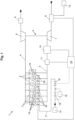
- Figure 1 shows an internal combustion engine 1 comprising an intake manifold 3 which can provide gaseous medium (air, a mixture of air and ammonia in gaseous form, a mixture of air and ammonia partly in liquid and partly in gaseous form, one of the aforementioned with a combustion promoter in liquid or gaseous form) to a plurality of piston-cylinder-units, at least one intercooler 10 coupled to the intake manifold 3 and at least one cylinder head with a plurality of piston-cylinder-units.
- gaseous medium air, a mixture of air and ammonia in gaseous form, a mixture of air and ammonia partly in liquid and partly in gaseous form, one of the aforementioned with a combustion promoter in liquid or gaseous form
- Each piston-cylinder-unit has at least a cylindrical main combustion chamber 2 for combustion of a combustion charge, a volume of the main combustion chamber 2 being defined by the at least one cylinder head and a reciprocally moving piston, the motion of the piston defining a variable volume geometry of the main combustion chamber 2 preferably having a geometrical compression ratio between 10 and 20.
- Each piston-cylinder-unit is provided with a prechamber 19 in which the ignition device is arranged.
- the ammonia enriched with hydrogen generated by a reformer 15 is provided to the prechambers 19 via prechamber valves 20 (which can be, by way of example, in the form of injectors).
- each piston-cylinder-unit has at least one intake valve coupled to the intake manifold 3 and an ignition device to start combustion of the combustion charge.
- the internal combustion engine 1 is provided with at least one ammonia source (two ammonia sources 13, 14 are shown in the figures) for providing ammonia to each piston-cylinder-unit as part of the combustion charge via the intake manifold 3 and the at least one intake valve as part of gaseous medium in form of a mixture of at least air and ammonia.
- at least one ammonia source two ammonia sources 13, 14 are shown in the figures
- the internal combustion engine 1 has a control device 12 which is configured to control the intercooler 10 to provide gaseous medium with a temperature of at least 40 °C to the intake manifold and control a lambda of the combustion charge inside each main combustion chamber 2 to be between 0,9 and 1,2 (in this embodiment by controlling a gas mixer 8 to which one of the ammonia sources 13, 14 is coupled).
- the control device 12 is further configured to control a throttle valve 11 and a first control valve 16 which allows addition of ammonia coming from an ammonia source 14 enriched with hydrogen generated by a reformer 15 to the prechambers 19 via an ammonia supply line 17 and the prechamber valves 20.
- the hydrogen source comprises not only the reformer but also a bypass line in which a second control valve 18 is arranged and the amount of hydrogen-enriched ammonia provided to the ammonia supply line 17 can be adjustably controlled by the control device 12 via the second control valve 18. If no second control valve 18 is provided a fixed amount of hydrogen-enriched ammonia can be achieved by suitably choosing a pressure of the ammonia source 14 and/or a diameter of the bypass line and/or the dimension of the reformer 15. It should be noted that the provision of a bypass line is not necessary and the reformer 15 could be the only connection between the ammonia source 14 and the first control valve 16.
- ammonia sources 13, 14 instead of two ammonia sources 13, 14 a single ammonia source 13, 14 to provide ammonia to both the intake manifold 3 and the hydrogen source could be used.
- the gaseous medium provided to the intake manifold 3 is charged by a compressor 7 of a turbocharger 5 which is driven by an exhaust turbine 6 of the turbocharger 5 which is arranged in the exhaust manifold 4.
- a catalytic converter 9 is also coupled to the exhaust manifold 4.
Landscapes
- Engineering & Computer Science (AREA)
- Chemical & Material Sciences (AREA)
- Combustion & Propulsion (AREA)
- Mechanical Engineering (AREA)
- General Engineering & Computer Science (AREA)
- Oil, Petroleum & Natural Gas (AREA)
- General Chemical & Material Sciences (AREA)
- Chemical Kinetics & Catalysis (AREA)
- Theoretical Computer Science (AREA)
- Signal Processing (AREA)
- Physics & Mathematics (AREA)
- Thermal Sciences (AREA)
- Output Control And Ontrol Of Special Type Engine (AREA)
- Combustion Methods Of Internal-Combustion Engines (AREA)
Description
- The invention concerns an internal combustion engine in which a main fuel for internal combustion is ammonia (NH3). In another aspect the invention concerns a genset for generation of electric power.
- Such internal combustion engines are disclosed in
US 2011/0114069 A1 ,US 2011/0259290A1 ,EP 2 378 094 A1US 2010/0019506 A1 ,WO 2019/035718 A1 andJP H05 332152 A -
US 3,455,282 discloses an internal combustion engine having main combustion chambers with a compression ratio between 12 and 16 which are provided with a spark plug to start combustion of a combustion charge consisting of air and ammonia. The addition of small quantities of hydrogen as a combustion promoter is discussed. - Another internal combustion engine where ammonia is used as a fuel is disclosed in
EP 3 669 059 A1 - It is an object of the invention to provide an internal combustion engine with an improved operability of burning ammonia as a main fuel.
- It is another object of the invention to provide a genset for generation of electric power.
- This object is achieved by an internal combustion engine having the features of claim 1 and a genset comprising an electric generator coupled to such an internal combustion engine. Embodiments of the invention are defined in the dependent claims.
- In an internal combustion engine according to the invention there is provided at least:
- an intake manifold which can provide gaseous medium (air, or a mixture of air and ammonia in gaseous form, or a mixture of air and ammonia partly in liquid and partly in gaseous form, or one of the aforementioned with a combustion promoter in liquid or gaseous form) to a plurality of piston-cylinder-units
- at least one cylinder head with a plurality of piston-cylinder-units, each piston cylinder-unit being provided with a prechamber
- at least one ammonia source for providing ammonia to each piston-cylinder-unit as part of the combustion charge (at least one other part of the combustion charge being air) and to the prechambers
- at least one hydrogen source for providing hydrogen to the prechambers via at least one prechamber valve of each piston-cylinder-unit
- Aside from the prechamber each piston-cylinder-unit has at least:
- a (preferably cylindrical) main combustion chamber for combustion of a combustion charge, a volume of the main combustion chamber being defined by the at least one cylinder head and a reciprocally moving piston, the motion of the piston preferably defining a variable volume of the main combustion chamber
- at least one intake valve coupled to the intake manifold
- an ignition device arranged in the prechamber to start combustion of the combustion charge indirectly via flame torches which enter the main combustion chamber from the prechamber and are created by the ignition of an ignitable air-fuel-mixture inside the prechamber
- The at least one ammonia source can provide ammonia:
- to the main combustion chambers via the intake manifold and the at least one intake valve as part of a mixture of at least air and ammonia and
- to the prechambers via the at least one prechamber valve provided to the prechamber of each piston-cylinder-unit
- The engine further comprises a control device to operate the internal combustion engine.
- The control device is configured to at least control an actuator for controlling a ratio of hydrogen to ammonia of hydrogen-enriched ammonia provided to the prechambers.
- The at least one hydrogen source can comprise at least one hydrogen tank and/or a hydrogen supply line, and comprises at least one reformer for cracking ammonia.
- The use of a reformer as part of the at least one hydrogen source (or as the at least one hydrogen source, if there are no other parts such as a control valve and/or a bypass line) allows on-demand production of hydrogen in an amount adjusted to the need as combustion promoter in the prechambers. No hydrogen tank for storage of hydrogen is needed. A small reformer can be used.
- If on-demand production of hydrogen is to be used at least the following operating parameters should be measured using sensors known in the art:
- engine load, and/or
- temperature of the gaseous medium inside the intake manifold, possibly after a turbocharger, if one is present, and an intercooler, if one is present, and/or
- exhaust gas temperature, and/or
- pressure of the gaseous medium inside the intake manifold, possibly after a turbocharger, if one is present
- Based on measured operating parameters and using, for example a look-up table and/or a model and/or a transfer function, the ratio of hydrogen to ammonia (wherein the hydrogen is to be produced in the reformer and mixed to the ammonia provided to the prechambers) can be determined. A control device can control (open-looped or closed-looped) an actuator, for example a control valve, to provide this amount.
- As a general rule:
- the lower an engine load, the higher the ratio of hydrogen to ammonia should be
- the lower the temperature of the gaseous medium inside the intake manifold, the higher the ratio of hydrogen to ammonia should be
- the higher the exhaust gas temperature, the higher the ratio of hydrogen to ammonia should be
- the lower the pressure of the gaseous medium inside the intake manifold, the higher the ratio of hydrogen to ammonia should be
- The above-said is also valid if hydrogen from a hydrogen tank or a supply line is to be used instead of or together with hydrogen from the reformer of the at least one hydrogen source.
- By way of example the at least one hydrogen source is configured to provide hydrogen to the prechamber of each piston-cylinder-unit in a range of 0 to 10 mass%, preferably of 0 to 5 mass%, in particular 0 to 3 mass% (note that all mass% of hydrogen are given with respect to the total fuel mass brought into a prechamber).
- In some embodiments the control device is configured to at least control a lambda of the combustion charge inside each main combustion chamber to be between 0,9 and 1,2, preferably between 0,98 and 1,02.
- In such embodiments it can be provided that the engine further comprises at least one intercooler coupled to the intake manifold and the control device being further configured to configured to control the intercooler to provide gaseous medium to the intake manifold with a temperature of at least 40 °C, preferably with at least 60 °C, and preferably with a temperature below 220 °C.
- Preferably the control device is configured to control the ignition device to start combustion of the combustion charge in each piston-cylinder-unit between -35 degrees to -10 degrees before the piston reaches top dead center (TDC).
- In some embodiments the motion of the piston defines a variable volume geometry of the main combustion chamber having a geometrical compression ratio between 10 and 20, preferably 12 and 18, in particular preferably between 14 and 18.
- Preferably an internal combustion engine according to the invention can be provided wherein a diameter of each main combustion chamber is at least 130 mm.
- In some embodiments the internal combustion engine comprises an exhaust manifold coupled to the plurality of piston-cylinder-units.
- In these embodiments there can be provided at least one catalytic converter, preferably a three-way-catalytic-converter or a SCR-converter, coupled to the exhaust manifold.
- In some embodiments the internal combustion engine comprises at least one turbocharger to charge the gaseous medium provided to the intake manifold.
- In some embodiments a brake mean effective pressure of the internal combustion engine is higher than 10 bar, preferably higher than 15 bar, in particular higher than 18 bar.
- Preferably, at least one valve of the at least one prechamber valve for providing ammonia to the prechamber is a gas valve for providing ammonia in gaseous form, possibly mixed with air, to the prechamber, enriched with hydrogen.
- In some embodiments the control device is configured to provide ammonia to the main combustion chamber in liquid form after opening of the at least one intake valve until 50 degrees crank angle before the piston reaches TDC. This ensures that ammonia is introduced when the pressure in the cylinder is not too high to be negative with respect to the energy balance (such that ammonia does not have to be injected with too high a pressure or too late in the compression stage).
- If ammonia in liquid form is used it should be considered that for combustion the ammonia has to be evaporated which needs additional energy when compared to using gaseous ammonia. To provide the additional energy it is advantageous to (compared to when gaseous ammonia is used):
- to increase the temperature of the gaseous medium which is to be mixed with the liquid ammonia, and/or
- to design the combustion chambers with a higher geometrical compression ratio to reach a desired temperature for combustion
- In some embodiments the ammonia source provides or stores ammonia in liquid form and there is provided a heat exchanger to use energy of exhaust gas to evaporate the ammonia into a gaseous form which is then provided to the main combustion chambers.
- In some embodiments the internal combustion engine can be provided with:
- optionally at least one turbocharger followed by
- at least one intercooler
- optionally followed by a throttle valve
- followed by the intake manifold which is coupled to
- the piston-cylinder-units which are coupled to
- the exhaust manifold followed by
- a turbine of the optional at least one turbocharger followed by
- an optional catalytic converter followed by
- an optional heat exchanger
- In some embodiments the control device is configured to control the intake valves and the exhaust valves of the piston-cylinder-units with overlapping opening times to provide internal EGR (exhaust gas recirculation), preferably with a rate (defined as mass of EGR/(mass of fuel + mass of air + mass of EGR) larger than 0 % and below 30 %, in particular with a rate between 1 % and 20 %.
- Embodiments of the invention are discussed with reference to
figure 1 . -
Figure 1 shows an internal combustion engine 1 comprising anintake manifold 3 which can provide gaseous medium (air, a mixture of air and ammonia in gaseous form, a mixture of air and ammonia partly in liquid and partly in gaseous form, one of the aforementioned with a combustion promoter in liquid or gaseous form) to a plurality of piston-cylinder-units, at least oneintercooler 10 coupled to theintake manifold 3 and at least one cylinder head with a plurality of piston-cylinder-units. - Each piston-cylinder-unit has at least a cylindrical
main combustion chamber 2 for combustion of a combustion charge, a volume of themain combustion chamber 2 being defined by the at least one cylinder head and a reciprocally moving piston, the motion of the piston defining a variable volume geometry of themain combustion chamber 2 preferably having a geometrical compression ratio between 10 and 20. - Each piston-cylinder-unit is provided with a
prechamber 19 in which the ignition device is arranged. The ammonia enriched with hydrogen generated by areformer 15 is provided to theprechambers 19 via prechamber valves 20 (which can be, by way of example, in the form of injectors). - Furthermore, each piston-cylinder-unit has at least one intake valve coupled to the
intake manifold 3 and an ignition device to start combustion of the combustion charge. - The internal combustion engine 1 is provided with at least one ammonia source (two
ammonia sources intake manifold 3 and the at least one intake valve as part of gaseous medium in form of a mixture of at least air and ammonia. - The internal combustion engine 1 has a control device 12 which is configured to control the
intercooler 10 to provide gaseous medium with a temperature of at least 40 °C to the intake manifold and control a lambda of the combustion charge inside eachmain combustion chamber 2 to be between 0,9 and 1,2 (in this embodiment by controlling agas mixer 8 to which one of theammonia sources - The control device 12 is further configured to control a
throttle valve 11 and afirst control valve 16 which allows addition of ammonia coming from anammonia source 14 enriched with hydrogen generated by areformer 15 to theprechambers 19 via anammonia supply line 17 and theprechamber valves 20. - In the shown embodiment the hydrogen source comprises not only the reformer but also a bypass line in which a
second control valve 18 is arranged and the amount of hydrogen-enriched ammonia provided to theammonia supply line 17 can be adjustably controlled by the control device 12 via thesecond control valve 18. If nosecond control valve 18 is provided a fixed amount of hydrogen-enriched ammonia can be achieved by suitably choosing a pressure of theammonia source 14 and/or a diameter of the bypass line and/or the dimension of thereformer 15. It should be noted that the provision of a bypass line is not necessary and thereformer 15 could be the only connection between theammonia source 14 and thefirst control valve 16. - Instead of two
ammonia sources 13, 14 asingle ammonia source intake manifold 3 and the hydrogen source could be used. - The gaseous medium provided to the
intake manifold 3 is charged by acompressor 7 of aturbocharger 5 which is driven by anexhaust turbine 6 of theturbocharger 5 which is arranged in theexhaust manifold 4. - A
catalytic converter 9 is also coupled to theexhaust manifold 4. -
- 1
- internal combustion engine
- 2
- main combustion chamber
- 3
- intake manifold
- 4
- exhaust manifold
- 5
- turbocharger
- 6
- exhaust turbine
- 7
- compressor
- 8
- gas mixer
- 9
- catalytic converter
- 10
- intercooler
- 11
- throttle valve
- 12
- control device
- 13
- ammonia source
- 14
- ammonia source
- 15
- reformer
- 16
- first control valve
- 17
- ammonia supply line
- 18
- second control valve
- 19
- prechamber
- 20
- prechamber valve
- 21
- ammonia source
Claims (16)
- Internal combustion engine (1) comprising:- an intake manifold (3) which can provide gaseous medium to a plurality of piston-cylinder-units;- at least one cylinder head with the plurality of piston-cylinder-units, each piston-cylinder-unit having at least• a main combustion chamber (2) for combustion of a combustion charge, a volume of the main combustion chamber (2) being defined by the at least one cylinder head and a reciprocally moving piston,• at least one intake valve for coupling the main combustion chamber (2) to the intake manifold (3),• a prechamber (19) which is coupled to the main combustion chamber (2) and• an ignition device arranged in the prechamber (19) to start combustion of the combustion charge indirectly via flame torches which enter the main combustion chamber (2) from the prechamber (19) and are created by the ignition of an ignitable air-fuel-mixture inside the prechamber (19);- at least one ammonia source (13, 14) for providing ammonia to each piston-cylinder-unit• via the intake manifold (3) and the at least one intake valve as part of gaseous medium in form of a mixture of at least air and ammonia as part of the combustion charge and• via at least one prechamber valve (20) provided to the prechamber (19);- at least one hydrogen source for providing hydrogen to the prechamber via the at least one prechamber valve of each piston-cylinder-unit, the at least one hydrogen source comprising at least one reformer (15) for cracking ammonia; and- a control device (12) to operate the internal combustion engine (1), wherein the control device (12) is configured to at least control an actuator for controlling a ratio of hydrogen to ammonia of hydrogen-enriched ammonia provided to the prechamber (19).
- The engine of claim 1, wherein the at least one hydrogen source comprises at least one hydrogen tank and/or a hydrogen supply line.
- The engine of at least one of the preceding claims wherein the control device (12) is configured to at least control a lambda of the combustion charge inside each main combustion chamber (2) to be between 0,9 and 1,2, preferably between 0,98 and 1,02.
- The engine of the preceding claim further comprising at least one intercooler (10) coupled to the intake manifold (3) and the control device (12) being further configured to control the intercooler (10) to provide gaseous medium to the intake manifold (3) with a temperature of at least 40 °C, preferably with at least 60 °C, and preferably with a temperature below 220 °C.
- The engine of one at least one of the two preceding claims, wherein the control device (12) is configured to control the ignition device to start combustion of the combustion charge in each piston-cylinder-unit between -35 degrees to -10 degrees before TDC.
- The engine of at least one of the preceding claims, wherein the motion of the piston defines a variable volume geometry of the main combustion chamber having a geometrical compression ratio between 10 and 20, preferably 12 and 18, in particular preferably between 14 and 18.
- The engine of at least one of the preceding claims, wherein the hydrogen source is configured to provide hydrogen to each prechamber (19) in a range of 0 to 10 mass%, preferably of 0 to 5 mass%, in particular 0 to 3 mass%.
- The engine of at least one of the preceding claims, wherein each main combustion chamber (2) has a cylindrical cross-section with a diameter of at least 130 mm.
- The engine of at least one of the preceding claims, wherein the internal combustion engine (1) comprises an exhaust manifold (4) coupled to the plurality of piston-cylinder-units by exhaust valves and, preferably, at least one catalytic converter (9), in particular a three-way-catalytic-converter or a SCR converter, coupled to the exhaust manifold (4).
- The engine of the preceding claim, wherein the control device (12) is configured to control the intake valves and the exhaust valves of the piston-cylinder-units with overlapping opening times to provide internal EGR, preferably with a rate larger than 0 % and below 30 %, in particular with a rate between 1 % and 20 %.
- The engine of at least one of the preceding claims, wherein the internal combustion engine (1) comprises at least one turbocharger (5) to charge the gaseous medium provided to the intake manifold (3).
- The engine of at least one of the preceding claims, wherein a brake mean effective pressure of the internal combustion engine (1) is higher than 10 bar, preferably higher than 15 bar, in particular higher than 18 bar.
- The engine of the preceding claim, wherein at least one of the at least one prechamber valve (20) for providing ammonia to the prechamber (19) is a gas valve for providing ammonia in gaseous form, possibly mixed with air, to the prechamber (19).
- The engine of at least one of the preceding claims wherein the control device (12) is configured to provide ammonia to the main combustion chamber (2) in liquid form after opening of the at least one intake valve until 50 degrees crank angle before the piston reaches TDC.
- The engine of at least one of the preceding claims, wherein the at least one ammonia source (13, 14) stores ammonia in liquid form and there is provided a heat exchanger to use energy of exhaust gas to evaporate the ammonia into a gaseous form which is then provided to the main combustion chamber (2).
- A genset for generation of electrical power comprising an electric generator coupled an internal combustion engine (1) of at least one of the preceding claims.
Applications Claiming Priority (1)
| Application Number | Priority Date | Filing Date | Title |
|---|---|---|---|
| PCT/AT2021/060128 WO2022221890A1 (en) | 2021-04-19 | 2021-04-19 | Internal combustion engine |
Publications (3)
| Publication Number | Publication Date |
|---|---|
| EP4326981A1 EP4326981A1 (en) | 2024-02-28 |
| EP4326981B1 true EP4326981B1 (en) | 2025-03-12 |
| EP4326981C0 EP4326981C0 (en) | 2025-03-12 |
Family
ID=75690060
Family Applications (1)
| Application Number | Title | Priority Date | Filing Date |
|---|---|---|---|
| EP21721820.5A Active EP4326981B1 (en) | 2021-04-19 | 2021-04-19 | Internal combustion engine |
Country Status (4)
| Country | Link |
|---|---|
| US (1) | US20240191665A1 (en) |
| EP (1) | EP4326981B1 (en) |
| CA (1) | CA3203636A1 (en) |
| WO (1) | WO2022221890A1 (en) |
Families Citing this family (6)
| Publication number | Priority date | Publication date | Assignee | Title |
|---|---|---|---|---|
| US11982241B2 (en) * | 2021-12-22 | 2024-05-14 | Transportation Ip Holdings, Llc | Methods and systems for multi-fuel engine |
| DE102022107928B4 (en) | 2022-04-04 | 2023-11-30 | Green AP GmbH | Internal combustion engine, especially for a motor vehicle |
| CN115217622B (en) * | 2022-07-15 | 2024-01-30 | 天津大学 | An ammonia-hydrogen fusion fuel control system based on reactivity control |
| CN116291976A (en) * | 2023-02-20 | 2023-06-23 | 清华大学 | Ammonia-hydrogen fusion internal combustion engine system and its fuel supply control method |
| US12552419B2 (en) * | 2023-10-31 | 2026-02-17 | Cummins Power Generation Inc. | Ammonia cracking for multi-fuel engines |
| CN117780523B (en) * | 2024-02-27 | 2024-06-18 | 潍柴动力股份有限公司 | A control method, device, equipment and medium for a hydrogen engine combustion system |
Family Cites Families (14)
| Publication number | Priority date | Publication date | Assignee | Title |
|---|---|---|---|---|
| US3455282A (en) | 1967-09-25 | 1969-07-15 | Continental Aviat & Eng Corp | Combustion chamber for burning anhydrous ammonia |
| JPS51138223A (en) * | 1975-05-27 | 1976-11-29 | Nissan Motor Co Ltd | Gas generator |
| JPH05332152A (en) * | 1991-06-25 | 1993-12-14 | Koji Korematsu | Ammonia combustion engine |
| EP1372839A4 (en) * | 2001-03-02 | 2006-11-29 | Mesofuel Inc | Ammonia-based hydrogen generation apparatus and method for using same |
| US20100019506A1 (en) | 2008-07-22 | 2010-01-28 | Caterpillar Inc. | Power system having an ammonia fueled engine |
| JP5287265B2 (en) | 2009-01-08 | 2013-09-11 | トヨタ自動車株式会社 | Ammonia combustion internal combustion engine |
| US20110114069A1 (en) | 2009-11-16 | 2011-05-19 | Shawn Grannell | Apparatus, system and method for operating an oxygen-enriched ammonia-fueled spark ignition engine |
| US8904994B2 (en) | 2010-04-26 | 2014-12-09 | Toyota Jidosha Kabushiki Kaisha | Ammonia burning internal combustion engine |
| CN104640628B (en) * | 2012-09-20 | 2016-11-16 | 国立大学法人东京工业大学 | Generate hydrogen catalyst and the manufacture method of hydrogen |
| NO343554B1 (en) | 2017-08-14 | 2019-04-01 | Lars Harald Heggen | Zero discharge propulsion system and ammonia fuel generating system |
| GB2602037A (en) * | 2020-12-16 | 2022-06-22 | Siemens Energy Global Gmbh & Co Kg | Method of operating a combustor for a gas turbine |
| US11773777B2 (en) * | 2020-12-18 | 2023-10-03 | New Wave Hydrogen, Inc. | Zero-emission jet engine employing a dual-fuel mix of ammonia and hydrogen using a wave |
| CN117795185A (en) * | 2021-06-02 | 2024-03-29 | 西港燃料系统加拿大公司 | Device and method for fuel injection and/or fuel ignition in an internal combustion engine |
| CN115217622B (en) * | 2022-07-15 | 2024-01-30 | 天津大学 | An ammonia-hydrogen fusion fuel control system based on reactivity control |
-
2021
- 2021-04-19 CA CA3203636A patent/CA3203636A1/en active Pending
- 2021-04-19 EP EP21721820.5A patent/EP4326981B1/en active Active
- 2021-04-19 WO PCT/AT2021/060128 patent/WO2022221890A1/en not_active Ceased
- 2021-04-19 US US18/556,323 patent/US20240191665A1/en active Pending
Also Published As
| Publication number | Publication date |
|---|---|
| WO2022221890A1 (en) | 2022-10-27 |
| US20240191665A1 (en) | 2024-06-13 |
| EP4326981A1 (en) | 2024-02-28 |
| EP4326981C0 (en) | 2025-03-12 |
| CA3203636A1 (en) | 2022-10-27 |
Similar Documents
| Publication | Publication Date | Title |
|---|---|---|
| EP4326981B1 (en) | Internal combustion engine | |
| CN114183262B (en) | Direct-injection hydrogen internal combustion engine in jet ignition cylinder of precombustion chamber and control method | |
| US4041910A (en) | Combustion engine | |
| US20130104850A1 (en) | Multi-fuel pre-mixed combustion system of internal combustion engine | |
| US11970965B2 (en) | Internal combustion engine | |
| CN114616386A (en) | Internal combustion engines and ignition systems with pre-chamber | |
| US20190170077A1 (en) | Combustion control method and combustion control system with variable excess air coefficient for gasoline engine | |
| US12078099B2 (en) | Hydrogen intake assembly for a hydrogen internal combustion engine | |
| CN117231357A (en) | In-cylinder direct injection ammonia-hydrogen internal combustion engine and control method thereof | |
| CN111219269A (en) | Partial premixing combustion system based on liquid hydrogen fuel piston engine and engine | |
| CN114017178A (en) | Lean combustion control method and device and hydrogen engine system | |
| CN114856842B (en) | A combustion control system and method for an internal combustion engine based on HHO | |
| WO2021005344A1 (en) | Hydrogen fuelled internal combustion engine | |
| CN113574261A (en) | Method for operating an internal combustion engine | |
| EP4396453A1 (en) | Internal combustion engine and a method for operating an internal combustion engine | |
| US12215655B2 (en) | Internal combustion engine | |
| US12085030B2 (en) | Internal combustion engine and a method for operating such an internal combustion | |
| CN114017179A (en) | Lean combustion system and method | |
| WO2021159153A1 (en) | Internal combustion engine | |
| EP3864267B1 (en) | A pre-chamber arrangement for a gas engine and a gas engine | |
| RU2163975C1 (en) | Internal combustion engine operation method | |
| EP4396452A1 (en) | Internal combustion engine and method for operating an internal combustion engine | |
| JP2025122916A (en) | Pre-chamber engine | |
| EA051492B1 (en) | FOUR-STROKE HYDROGEN-FUELLED INTERNAL COMBUSTION ENGINE | |
| US20210095604A1 (en) | Control method of variable stroke engine for reforming high-octane fuel under the flexible cylinder engine (fce) mode |
Legal Events
| Date | Code | Title | Description |
|---|---|---|---|
| STAA | Information on the status of an ep patent application or granted ep patent |
Free format text: STATUS: UNKNOWN |
|
| STAA | Information on the status of an ep patent application or granted ep patent |
Free format text: STATUS: THE INTERNATIONAL PUBLICATION HAS BEEN MADE |
|
| PUAI | Public reference made under article 153(3) epc to a published international application that has entered the european phase |
Free format text: ORIGINAL CODE: 0009012 |
|
| STAA | Information on the status of an ep patent application or granted ep patent |
Free format text: STATUS: REQUEST FOR EXAMINATION WAS MADE |
|
| 17P | Request for examination filed |
Effective date: 20230911 |
|
| AK | Designated contracting states |
Kind code of ref document: A1 Designated state(s): AL AT BE BG CH CY CZ DE DK EE ES FI FR GB GR HR HU IE IS IT LI LT LU LV MC MK MT NL NO PL PT RO RS SE SI SK SM TR |
|
| P01 | Opt-out of the competence of the unified patent court (upc) registered |
Effective date: 20240411 |
|
| DAV | Request for validation of the european patent (deleted) | ||
| DAX | Request for extension of the european patent (deleted) | ||
| RIC1 | Information provided on ipc code assigned before grant |
Ipc: F02D 41/00 20060101ALI20240930BHEP Ipc: F02D 29/06 20060101ALI20240930BHEP Ipc: F02D 19/08 20060101ALI20240930BHEP Ipc: F02D 19/06 20060101ALI20240930BHEP Ipc: F02D 13/02 20060101ALI20240930BHEP Ipc: F02B 43/10 20060101ALI20240930BHEP Ipc: F02B 19/12 20060101ALI20240930BHEP Ipc: F02M 21/02 20060101AFI20240930BHEP |
|
| GRAP | Despatch of communication of intention to grant a patent |
Free format text: ORIGINAL CODE: EPIDOSNIGR1 |
|
| STAA | Information on the status of an ep patent application or granted ep patent |
Free format text: STATUS: GRANT OF PATENT IS INTENDED |
|
| INTG | Intention to grant announced |
Effective date: 20241121 |
|
| GRAS | Grant fee paid |
Free format text: ORIGINAL CODE: EPIDOSNIGR3 |
|
| GRAA | (expected) grant |
Free format text: ORIGINAL CODE: 0009210 |
|
| STAA | Information on the status of an ep patent application or granted ep patent |
Free format text: STATUS: THE PATENT HAS BEEN GRANTED |
|
| AK | Designated contracting states |
Kind code of ref document: B1 Designated state(s): AL AT BE BG CH CY CZ DE DK EE ES FI FR GB GR HR HU IE IS IT LI LT LU LV MC MK MT NL NO PL PT RO RS SE SI SK SM TR |
|
| REG | Reference to a national code |
Ref country code: GB Ref legal event code: FG4D |
|
| REG | Reference to a national code |
Ref country code: CH Ref legal event code: EP |
|
| REG | Reference to a national code |
Ref country code: DE Ref legal event code: R096 Ref document number: 602021027500 Country of ref document: DE |
|
| REG | Reference to a national code |
Ref country code: IE Ref legal event code: FG4D |
|
| P04 | Withdrawal of opt-out of the competence of the unified patent court (upc) registered |
Free format text: CASE NUMBER: APP_15706/2025 Effective date: 20250401 |
|
| U01 | Request for unitary effect filed |
Effective date: 20250328 |
|
| U07 | Unitary effect registered |
Designated state(s): AT BE BG DE DK EE FI FR IT LT LU LV MT NL PT RO SE SI Effective date: 20250403 |
|
| U20 | Renewal fee for the european patent with unitary effect paid |
Year of fee payment: 5 Effective date: 20250423 |
|
| PG25 | Lapsed in a contracting state [announced via postgrant information from national office to epo] |
Ref country code: RS Free format text: LAPSE BECAUSE OF FAILURE TO SUBMIT A TRANSLATION OF THE DESCRIPTION OR TO PAY THE FEE WITHIN THE PRESCRIBED TIME-LIMIT Effective date: 20250612 |
|
| PG25 | Lapsed in a contracting state [announced via postgrant information from national office to epo] |
Ref country code: ES Free format text: LAPSE BECAUSE OF FAILURE TO SUBMIT A TRANSLATION OF THE DESCRIPTION OR TO PAY THE FEE WITHIN THE PRESCRIBED TIME-LIMIT Effective date: 20250312 |
|
| PG25 | Lapsed in a contracting state [announced via postgrant information from national office to epo] |
Ref country code: NO Free format text: LAPSE BECAUSE OF FAILURE TO SUBMIT A TRANSLATION OF THE DESCRIPTION OR TO PAY THE FEE WITHIN THE PRESCRIBED TIME-LIMIT Effective date: 20250612 |
|
| PG25 | Lapsed in a contracting state [announced via postgrant information from national office to epo] |
Ref country code: HR Free format text: LAPSE BECAUSE OF FAILURE TO SUBMIT A TRANSLATION OF THE DESCRIPTION OR TO PAY THE FEE WITHIN THE PRESCRIBED TIME-LIMIT Effective date: 20250312 |
|
| PG25 | Lapsed in a contracting state [announced via postgrant information from national office to epo] |
Ref country code: GR Free format text: LAPSE BECAUSE OF FAILURE TO SUBMIT A TRANSLATION OF THE DESCRIPTION OR TO PAY THE FEE WITHIN THE PRESCRIBED TIME-LIMIT Effective date: 20250613 |
|
| PG25 | Lapsed in a contracting state [announced via postgrant information from national office to epo] |
Ref country code: SM Free format text: LAPSE BECAUSE OF FAILURE TO SUBMIT A TRANSLATION OF THE DESCRIPTION OR TO PAY THE FEE WITHIN THE PRESCRIBED TIME-LIMIT Effective date: 20250312 |
|
| PG25 | Lapsed in a contracting state [announced via postgrant information from national office to epo] |
Ref country code: PL Free format text: LAPSE BECAUSE OF FAILURE TO SUBMIT A TRANSLATION OF THE DESCRIPTION OR TO PAY THE FEE WITHIN THE PRESCRIBED TIME-LIMIT Effective date: 20250312 |
|
| PG25 | Lapsed in a contracting state [announced via postgrant information from national office to epo] |
Ref country code: CZ Free format text: LAPSE BECAUSE OF FAILURE TO SUBMIT A TRANSLATION OF THE DESCRIPTION OR TO PAY THE FEE WITHIN THE PRESCRIBED TIME-LIMIT Effective date: 20250312 |
|
| PG25 | Lapsed in a contracting state [announced via postgrant information from national office to epo] |
Ref country code: SK Free format text: LAPSE BECAUSE OF FAILURE TO SUBMIT A TRANSLATION OF THE DESCRIPTION OR TO PAY THE FEE WITHIN THE PRESCRIBED TIME-LIMIT Effective date: 20250312 |
|
| PG25 | Lapsed in a contracting state [announced via postgrant information from national office to epo] |
Ref country code: IS Free format text: LAPSE BECAUSE OF FAILURE TO SUBMIT A TRANSLATION OF THE DESCRIPTION OR TO PAY THE FEE WITHIN THE PRESCRIBED TIME-LIMIT Effective date: 20250712 |
|
| REG | Reference to a national code |
Ref country code: CH Ref legal event code: H13 Free format text: ST27 STATUS EVENT CODE: U-0-0-H10-H13 (AS PROVIDED BY THE NATIONAL OFFICE) Effective date: 20251125 |
|
| PG25 | Lapsed in a contracting state [announced via postgrant information from national office to epo] |
Ref country code: MC Free format text: LAPSE BECAUSE OF FAILURE TO SUBMIT A TRANSLATION OF THE DESCRIPTION OR TO PAY THE FEE WITHIN THE PRESCRIBED TIME-LIMIT Effective date: 20250312 |
|
| PLBE | No opposition filed within time limit |
Free format text: ORIGINAL CODE: 0009261 |
|
| STAA | Information on the status of an ep patent application or granted ep patent |
Free format text: STATUS: NO OPPOSITION FILED WITHIN TIME LIMIT |
|
| PG25 | Lapsed in a contracting state [announced via postgrant information from national office to epo] |
Ref country code: CH Free format text: LAPSE BECAUSE OF NON-PAYMENT OF DUE FEES Effective date: 20250430 |
|
| REG | Reference to a national code |
Ref country code: CH Ref legal event code: L10 Free format text: ST27 STATUS EVENT CODE: U-0-0-L10-L00 (AS PROVIDED BY THE NATIONAL OFFICE) Effective date: 20260121 |
|
| 26N | No opposition filed |
Effective date: 20251215 |
|
| PGFP | Annual fee paid to national office [announced via postgrant information from national office to epo] |
Ref country code: GB Payment date: 20260319 Year of fee payment: 6 |
|
| PG25 | Lapsed in a contracting state [announced via postgrant information from national office to epo] |
Ref country code: IE Free format text: LAPSE BECAUSE OF NON-PAYMENT OF DUE FEES Effective date: 20250419 |
|
| U20 | Renewal fee for the european patent with unitary effect paid |
Year of fee payment: 6 Effective date: 20260319 |