EP4326011A2 - Systems and methods for shaping flexible circuits to improve routing and attachment - Google Patents
Systems and methods for shaping flexible circuits to improve routing and attachment Download PDFInfo
- Publication number
- EP4326011A2 EP4326011A2 EP23179564.2A EP23179564A EP4326011A2 EP 4326011 A2 EP4326011 A2 EP 4326011A2 EP 23179564 A EP23179564 A EP 23179564A EP 4326011 A2 EP4326011 A2 EP 4326011A2
- Authority
- EP
- European Patent Office
- Prior art keywords
- tool
- shaping
- conductive
- portions
- shape
- Prior art date
- Legal status (The legal status is an assumption and is not a legal conclusion. Google has not performed a legal analysis and makes no representation as to the accuracy of the status listed.)
- Pending
Links
Images


Classifications
-
- H—ELECTRICITY
- H05—ELECTRIC TECHNIQUES NOT OTHERWISE PROVIDED FOR
- H05K—PRINTED CIRCUITS; CASINGS OR CONSTRUCTIONAL DETAILS OF ELECTRIC APPARATUS; MANUFACTURE OF ASSEMBLAGES OF ELECTRICAL COMPONENTS
- H05K1/00—Printed circuits
- H05K1/02—Details
- H05K1/0277—Bendability or stretchability details
- H05K1/028—Bending or folding regions of flexible printed circuits
-
- B—PERFORMING OPERATIONS; TRANSPORTING
- B60—VEHICLES IN GENERAL
- B60R—VEHICLES, VEHICLE FITTINGS, OR VEHICLE PARTS, NOT OTHERWISE PROVIDED FOR
- B60R16/00—Electric or fluid circuits specially adapted for vehicles and not otherwise provided for; Arrangement of elements of electric or fluid circuits specially adapted for vehicles and not otherwise provided for
- B60R16/02—Electric or fluid circuits specially adapted for vehicles and not otherwise provided for; Arrangement of elements of electric or fluid circuits specially adapted for vehicles and not otherwise provided for electric constitutive elements
-
- H—ELECTRICITY
- H05—ELECTRIC TECHNIQUES NOT OTHERWISE PROVIDED FOR
- H05K—PRINTED CIRCUITS; CASINGS OR CONSTRUCTIONAL DETAILS OF ELECTRIC APPARATUS; MANUFACTURE OF ASSEMBLAGES OF ELECTRICAL COMPONENTS
- H05K1/00—Printed circuits
- H05K1/02—Details
- H05K1/0201—Thermal arrangements, e.g. for cooling, heating or preventing overheating
- H05K1/0212—Printed circuits or mounted components having integral heating means
-
- H—ELECTRICITY
- H05—ELECTRIC TECHNIQUES NOT OTHERWISE PROVIDED FOR
- H05K—PRINTED CIRCUITS; CASINGS OR CONSTRUCTIONAL DETAILS OF ELECTRIC APPARATUS; MANUFACTURE OF ASSEMBLAGES OF ELECTRICAL COMPONENTS
- H05K1/00—Printed circuits
- H05K1/18—Printed circuits structurally associated with non-printed electric components
- H05K1/189—Printed circuits structurally associated with non-printed electric components characterised by the use of flexible or folded printed circuits
-
- H—ELECTRICITY
- H05—ELECTRIC TECHNIQUES NOT OTHERWISE PROVIDED FOR
- H05K—PRINTED CIRCUITS; CASINGS OR CONSTRUCTIONAL DETAILS OF ELECTRIC APPARATUS; MANUFACTURE OF ASSEMBLAGES OF ELECTRICAL COMPONENTS
- H05K3/00—Apparatus or processes for manufacturing printed circuits
- H05K3/0011—Working of insulating substrates or insulating layers
- H05K3/0014—Shaping of the substrate, e.g. by moulding
-
- H—ELECTRICITY
- H05—ELECTRIC TECHNIQUES NOT OTHERWISE PROVIDED FOR
- H05K—PRINTED CIRCUITS; CASINGS OR CONSTRUCTIONAL DETAILS OF ELECTRIC APPARATUS; MANUFACTURE OF ASSEMBLAGES OF ELECTRICAL COMPONENTS
- H05K3/00—Apparatus or processes for manufacturing printed circuits
- H05K3/0011—Working of insulating substrates or insulating layers
- H05K3/0017—Etching of the substrate by chemical or physical means
- H05K3/0026—Etching of the substrate by chemical or physical means by laser ablation
-
- H—ELECTRICITY
- H05—ELECTRIC TECHNIQUES NOT OTHERWISE PROVIDED FOR
- H05K—PRINTED CIRCUITS; CASINGS OR CONSTRUCTIONAL DETAILS OF ELECTRIC APPARATUS; MANUFACTURE OF ASSEMBLAGES OF ELECTRICAL COMPONENTS
- H05K3/00—Apparatus or processes for manufacturing printed circuits
- H05K3/0011—Working of insulating substrates or insulating layers
- H05K3/0017—Etching of the substrate by chemical or physical means
- H05K3/0026—Etching of the substrate by chemical or physical means by laser ablation
- H05K3/0032—Etching of the substrate by chemical or physical means by laser ablation of organic insulating material
-
- H—ELECTRICITY
- H05—ELECTRIC TECHNIQUES NOT OTHERWISE PROVIDED FOR
- H05K—PRINTED CIRCUITS; CASINGS OR CONSTRUCTIONAL DETAILS OF ELECTRIC APPARATUS; MANUFACTURE OF ASSEMBLAGES OF ELECTRICAL COMPONENTS
- H05K1/00—Printed circuits
- H05K1/02—Details
- H05K1/03—Use of materials for the substrate
- H05K1/0393—Flexible materials
-
- H—ELECTRICITY
- H05—ELECTRIC TECHNIQUES NOT OTHERWISE PROVIDED FOR
- H05K—PRINTED CIRCUITS; CASINGS OR CONSTRUCTIONAL DETAILS OF ELECTRIC APPARATUS; MANUFACTURE OF ASSEMBLAGES OF ELECTRICAL COMPONENTS
- H05K2201/00—Indexing scheme relating to printed circuits covered by H05K1/00
- H05K2201/01—Dielectrics
- H05K2201/0104—Properties and characteristics in general
- H05K2201/0129—Thermoplastic polymer, e.g. auto-adhesive layer; Shaping of thermoplastic polymer
-
- H—ELECTRICITY
- H05—ELECTRIC TECHNIQUES NOT OTHERWISE PROVIDED FOR
- H05K—PRINTED CIRCUITS; CASINGS OR CONSTRUCTIONAL DETAILS OF ELECTRIC APPARATUS; MANUFACTURE OF ASSEMBLAGES OF ELECTRICAL COMPONENTS
- H05K2201/00—Indexing scheme relating to printed circuits covered by H05K1/00
- H05K2201/05—Flexible printed circuits [FPCs]
- H05K2201/055—Folded back on itself
-
- H—ELECTRICITY
- H05—ELECTRIC TECHNIQUES NOT OTHERWISE PROVIDED FOR
- H05K—PRINTED CIRCUITS; CASINGS OR CONSTRUCTIONAL DETAILS OF ELECTRIC APPARATUS; MANUFACTURE OF ASSEMBLAGES OF ELECTRICAL COMPONENTS
- H05K2201/00—Indexing scheme relating to printed circuits covered by H05K1/00
- H05K2201/05—Flexible printed circuits [FPCs]
- H05K2201/056—Folded around rigid support or component
-
- H—ELECTRICITY
- H05—ELECTRIC TECHNIQUES NOT OTHERWISE PROVIDED FOR
- H05K—PRINTED CIRCUITS; CASINGS OR CONSTRUCTIONAL DETAILS OF ELECTRIC APPARATUS; MANUFACTURE OF ASSEMBLAGES OF ELECTRICAL COMPONENTS
- H05K2201/00—Indexing scheme relating to printed circuits covered by H05K1/00
- H05K2201/09—Shape and layout
- H05K2201/09009—Substrate related
- H05K2201/09036—Recesses or grooves in insulating substrate
-
- H—ELECTRICITY
- H05—ELECTRIC TECHNIQUES NOT OTHERWISE PROVIDED FOR
- H05K—PRINTED CIRCUITS; CASINGS OR CONSTRUCTIONAL DETAILS OF ELECTRIC APPARATUS; MANUFACTURE OF ASSEMBLAGES OF ELECTRICAL COMPONENTS
- H05K2201/00—Indexing scheme relating to printed circuits covered by H05K1/00
- H05K2201/09—Shape and layout
- H05K2201/09009—Substrate related
- H05K2201/091—Locally and permanently deformed areas including dielectric material
-
- H—ELECTRICITY
- H05—ELECTRIC TECHNIQUES NOT OTHERWISE PROVIDED FOR
- H05K—PRINTED CIRCUITS; CASINGS OR CONSTRUCTIONAL DETAILS OF ELECTRIC APPARATUS; MANUFACTURE OF ASSEMBLAGES OF ELECTRICAL COMPONENTS
- H05K2203/00—Indexing scheme relating to apparatus or processes for manufacturing printed circuits covered by H05K3/00
- H05K2203/01—Tools for processing; Objects used during processing
- H05K2203/0104—Tools for processing; Objects used during processing for patterning or coating
- H05K2203/0108—Male die used for patterning, punching or transferring
-
- H—ELECTRICITY
- H05—ELECTRIC TECHNIQUES NOT OTHERWISE PROVIDED FOR
- H05K—PRINTED CIRCUITS; CASINGS OR CONSTRUCTIONAL DETAILS OF ELECTRIC APPARATUS; MANUFACTURE OF ASSEMBLAGES OF ELECTRICAL COMPONENTS
- H05K2203/00—Indexing scheme relating to apparatus or processes for manufacturing printed circuits covered by H05K3/00
- H05K2203/01—Tools for processing; Objects used during processing
- H05K2203/0104—Tools for processing; Objects used during processing for patterning or coating
- H05K2203/0113—Female die used for patterning or transferring, e.g. temporary substrate having recessed pattern
-
- H—ELECTRICITY
- H05—ELECTRIC TECHNIQUES NOT OTHERWISE PROVIDED FOR
- H05K—PRINTED CIRCUITS; CASINGS OR CONSTRUCTIONAL DETAILS OF ELECTRIC APPARATUS; MANUFACTURE OF ASSEMBLAGES OF ELECTRICAL COMPONENTS
- H05K2203/00—Indexing scheme relating to apparatus or processes for manufacturing printed circuits covered by H05K3/00
- H05K2203/11—Treatments characterised by their effect, e.g. heating, cooling, roughening
- H05K2203/1105—Heating or thermal processing not related to soldering, firing, curing or laminating, e.g. for shaping the substrate or during finish plating
Definitions
- FCs flexible circuits
- EV electrified vehicle
- FCs flexible circuits
- electrical components controllers, sub-controllers, sensors/actuators, etc.
- FCs can be pre-processed to increase their flexibility. For example, full-thickness slits in the insulation material between the conductive circuit traces can be formed. Such slits, however, tend to tear further than intended over time. In addition, fully singulating the conductive circuit traces can result in their damage, especially over time after repetitive routing.
- a system for shaping a flexible circuit (FC) including a set of conductive traces disposed within a set of insulation layers comprises a non-conductive tool defining complimentary first and second tool portions and a shape therebetween, the tool being configured to receive a portion of the FC between the first and second tool portions, a set of conductive heating elements arranged substantially in parallel with each other and disposed within the first and second tool portions, and a power source configured to provide power to the conductive heating elements causing the conductive heating elements to generate heat energy to shape the FC portion without removing any of the FC portion.
- the shape is a waveform shape defining a series of peaks and valleys relative to the first and second tool portions.
- each conductive heating element is substantially aligned with a respective peak-valley pair in one of the first and second tool portions corresponding to a peak side of the respective peak-valley pair.
- the waveform shape is a triangular waveform shape for increasing flexibility or bendability of the FC perpendicular to its length.
- the waveform shape is a sinusoidal waveform shape for increasing rigidity or stiffness of the FC along its length.
- the first and second tool portions are arranged in a clamp configuration joined on one respective side by a hinge member and moveable relative to each other such that, when the first and second tool portions are separated from each other in an open position, the FC portion is positionable therein, and when the first and second tool portions are proximate to each other in a closed position, the FC portion is secured therein for shaping.
- the first and second portions are fixed relative to each other defining a slot or gap therebetween for insertion and shaping of the FC portion therebetween.
- some conductive heating elements of the set of conductive heating elements have different lengths such that the shaping achieves different widths of bends/folds in at least some of the set of insulation layers.
- the system further comprises a laser processing system configured to pre-process the FC portion to etch or remove a portion of the set of insulation layers in an area of the FC portion to promote the subsequent shaping.
- the power source is a battery system such that the system is movable to any desired position.
- the system further comprises an output device configured to generate at least one of an audible, visual, and tactile output after a shaping period of providing power to the set of conductive elements to shape the FC portion, wherein the shaping period has a sufficient duration to complete the shaping of the FC portion.
- a method of shaping an FC including a set of conductive traces disposed within a set of insulation layers comprises: providing a non-conductive tool defining complimentary first and second tool portions and a shape therebetween, the tool being configured to receive a portion of the FC between the first and second tool portions, providing a set of conductive heating elements arranged substantially in parallel with each other and disposed within the first and second tool portions, providing a power source configured to provide power to the conductive heating elements causing the conductive heating elements to generate heat energy, positioning the FC portion within the tool, and providing power to the conductive heating elements to shape the FC portion without removing any of the FC portion.
- the shape is a waveform shape defining a series of peaks and valleys relative to the first and second tool portions.
- each conductive heating element is substantially aligned with a respective peak-valley pair in one of the first and second tool portions corresponding to a peak side of the respective peak-valley pair.
- the waveform shape is a triangular waveform shape for increasing flexibility or bendability of the FC perpendicular to its length.
- the waveform shape is a sinusoidal waveform shape for increasing rigidity or stiffness of the FC along its length.
- the first and second tool portions are arranged in a clamp configuration joined on one respective side by a hinge member and moveable relative to each other such that, when the first and second tool portions are separated from each other in an open position, the FC portion is positionable therein, and when the first and second tool portions are proximate to each other in a closed position, the FC portion is secured therein for shaping.
- the first and second portions are fixed relative to each other defining a slot or gap therebetween for insertion and shaping of the FC portion therebetween.
- some conductive heating elements of the set of conductive heating elements have different lengths such that the shaping achieves different widths of bends/folds in at least some of the set of insulation layers.
- the method further comprises providing a laser processing system configured to etch or remove a portion of the set of insulation layers of the FC and pre-processing the FC portion with the laser processing system to promote the subsequent shaping.
- the power source is a battery system such that the tool with the set of conductive heating elements therein is movable to any desired position.
- the method further comprises providing an output device configured to generate at least one of an audible, visual, and tactile output, and actuating the output device after a shaping period of providing power to the set of conductive elements to shape the FC portion, wherein the shaping period has a sufficient duration to complete the shaping of the FC portion.
- an FC comprises: a set insulation layers, and a set of conductive circuit traces disposed within the set of one or more insulation layers, wherein the sets of insulation layers and conductive circuit traces collectively define a cross-sectional shape of the FC, and wherein the FC cross-sectional shape is a waveform shape to provide a desired alteration in flexibility/rigidity of the FC along one of its axes.
- the waveform shape is a triangular waveform shape for increasing flexibility or bendability of the FC perpendicular to its length.
- the waveform shape is a sinusoidal waveform shape for increasing rigidity or stiffness of the FC along its length.
- the set of insulation layers do not include any full-thickness slits or cuts therethrough.
- FCs are often slit, cut, singulated, or otherwise separated, typically through their full or entire thickness and longitudinally, to allow FC assemblies to be easily bent, gathered, or twisted in a specific area of the FC.
- FC separation methods increases risk of FC damage by producing individual FC "catch points” and reducing the FC assembly tensile strength to a tensile strength of a single conductive circuit (plus insulation).
- Such slits therefore, tend to tear further than intended over time.
- full singulation or separation often results in damage over time, especially after repetitive routing (e.g., during or after electrified vehicle electrical system maintenance).
- the systems and methods herein utilize a unique tool having conductive heating elements therein that generate heat energy to shape the FC portion (i.e., to temporarily make the insulation layer(s) of the FC portion pliable or shapable).
- the resulting shaped FC does not suffer from the permanent slits/cuts of conventional techniques, which could result in further tearing and/or damage to the conductive circuit traces.
- the shaped FC is easily routable and attachable (e.g., bendable around a pole-type object) in a tight/crowded environment, such as an electrical system of an electrified vehicle (EV).
- the FC 100 comprises a set of one or more conductive traces 108 formed of a conductive material (copper, aluminum, etc.) and arranged substantially parallel to each other lengthwise and within one or more dielectric or insulation layers 104.
- the FC 100 comprises two insulation layers 104a and 104b, which could be formed of dissimilar materials having different properties (flexibility, melting temperature, etc.).
- each insulation layer is formed of a non-conductive laminate or thermoplastic material (e.g., a thermoplastic polymer resin), such as, but not limited to, polyethylene naphthalate (PEN) and polyethylene terephthalate (PET).
- a thermoplastic polymer resin such as, but not limited to, polyethylene naphthalate (PEN) and polyethylene terephthalate (PET).
- the shaping process as performed by example shaping system 150 and described more fully described below, generally involves mechanically folding or forming and materially resetting (via heat) the insulation layer(s) 104 incorporating a longitudinal or angular shape (e.g., a triangular or sinusoidal waveform) that allows the FC 100 to be collapsed or "pinched" in specific areas or sections without damage.
- the heat is applied at the bend or crease point along the length of the fold area to set the plastic and maintain the bend position during the cycle of folding or bending the FC 100.
- the temperature is dependent on the material(s) utilized for the insulation layer(s) 104. Thickness of material in the bend or crease may increase or decrease retention of the fold.
- a cover or base film and/or an adhesive in the bend or crease could be removed without causing a cut edge in the insulation layer(s) 104 (retaining at least one layer of cover or base film to maintain FC stability).
- the FC 100 can be shaped to meet electrified vehicle routing and attachment requirements while maintaining the full strength of the FC 100.
- the shaping system 150 comprises a non-conductive tool 154, 300 defining complimentary first and second tool portions 304a, 304b and a shape therebetween (e.g., a triangular waveform shape 312).
- a shape therebetween e.g., a triangular waveform shape 3112.
- a triangular waveform is shown and described herein, it will be appreciated that the shaped FC could define any suitable repeating or non-repeating shape profile, such as a sinusoidal waveform.
- the tool 154, 300 is configured to receive a portion of the unshaped or pre-processed FC therebetween the first and second tool portions.
- a clamp configuration is provided where the first and second tool portions 304a, 304b are connected by a living hinge 316 to provide clearance in a vertical direction 320 for insertion of the FC 100 therebetween.
- the tool 154, 300 could provide another suitable means for receiving the FC 100, such as insertion via an end and pressure/rolling the FC 100 therebetween the first and second tool portions 304a, 304b.
- the tool 154 also comprises a set of conductive heating elements 158, 308a, 308b arranged substantially in parallel with each other and disposed within the first and second tool portions 304a, 304b.
- the heating elements 158, 308a, 308b are selectively powered by current from a power source 162, such as a battery or battery system.
- the power source 162 is a battery/battery system such that the shaping system 150 is mobile (e.g., a handheld unit), which could be preferable due to increased flexibility for installation. It will be appreciated that the power source 162 could also be a stationary power source, such as a traditional wall outlet.
- the shaping system 150 further comprises an output device 170 configured to generate an output (audio, visual, tactile, or some combination thereof) indicative of a status.
- the output device 170 could illuminate a light and/or produce an audible noise when the shaping process is complete (e.g., when the conductive heating elements 158, 308a, 308b have received power for a sufficient period).
- the shaping system 150 could optionally include or be associated with a laser processing or pre-processing system 166.
- This laser processing system 166 could be optionally used for laser processing of the unshaped FC prior to its insertion/shaping by the shaping system 150.
- a top portion 204a e.g., a slit
- both first and second insulation layers 104a, 104b could be removed by the laser processing system 166 and the shaped or pre-processed FC 200a could then be fed to the shaping system 150.
- a bottom portion 204b e.g., a slit of both the first and second insulation layers 104a, 104b could be removed by laser processing system 166 and the shaped or pre-processed FC 200b could then be fed to the shaping system 150.
- This optional pre-processing could further assist in the formation/shaping of the FC 100, such as, for example only, FCs 100 having thicker or multiple insulation layers 104.
- FIGS. 4A-4B views of an example FC 400 having triangular waveform shaped portions using the tool of FIGS. 3A-3B according to some implementations of the present disclosure are illustrated.
- one potential shape is a triangular waveform shape defining a series of peaks and valleys relative to the first and second tool portions 304a, 304b.
- each conductive heating element 308a, 308b is substantially aligned with a respective peak-valley pair in one of the first and second tool portions 304a, 304b corresponding to a peak side of the respective peak-valley pair.
- some conductive heating elements 308a, 308b of the set of conductive heating elements 158 have different lengths such that the shaping achieves different widths of bends/folds in at least some of the set of insulation layers.
- only a portion of the length of the FC could be shaped/processed as shown in FIGS. 4A-4B .
- a first portion 404 is not processed/shaped and a second portion 408 is processed/shaped, with a transitional or bunched portion 412 therebetween.
- only a portion of the FC 400 could be processed/shaped at a desired length point relative to an installation or routing feature, such as a pole-shaped object 420 as shown in FIG. 4B .
- the processed/shaped portion 408 easily bends around the pole-shaped object 420 at length point 416 to mitigate or prevent damage to the FC 400 (e.g., increased flexibility or bendability in the x-direction).
- FIGS. 5A-5B views of another example FC 500 having sinusoidal waveform shaped portions 504 using a different (but similar) tool as shown in FIGS. 3A-3B according to some implementations of the present disclosure are illustrated.
- the tool (not shown) to form/shape the sinusoidal waveform shape 504 as shown would be similar to FIGS. 3A-3B but would be sinusoidal rather than triangular, with, for example, conductive heating elements arranged in similar locations along the waveform shape 504 (e.g., peaks/valleys).
- FIG. 5A multiple insulation layers 508a, 508b are formed/shaped based on this waveform shape 504.
- FC 500 longitudinal extending sinusoidal or "wavy” undulations
- FIG. 6 a flow diagram of an example method 600 of shaping a portion of an FC using a system or tool/heating element(s) according to some implementations of the present disclosure is illustrated.
- an FC is provided with conductive trace(s) disposed between dielectric or insulation layer(s).
- optional laser preprocessing is performed to remove portion(s) of the insulation layer(s) to further promote or assist with the subsequent processing/shaping.
- a non-conductive tool defining a shape (triangular, sinusoidal, etc.) is provided.
- conductive heating element(s) are provided, such as within portions of the tool.
- a power source (stationary or mobile, such as a battery pack/system) is provided to selectively power the heating element(s).
- the FC is positioned within or relative to the tool and subsequently shaped by temporarily powering the heating element(s) using the powers source (e.g., until an end/complete indication is output or generated by an output device).
- the final processed/shaped FC is removed from the tool and then routed/attached in a desired environment, such as bending around a pole-type object in a vehicle electrical system. The method 600 then ends or returns to 604 for one or more additional cycles.
- Example embodiments are provided so that this disclosure will be thorough and will fully convey the scope to those who are skilled in the art. Numerous specific details are set forth such as examples of specific components, devices, and methods, to provide a thorough understanding of embodiments of the present disclosure. It will be apparent to those skilled in the art that specific details need not be employed, that example embodiments may be embodied in many different forms and that neither should be construed to limit the scope of the disclosure. In some example embodiments, well-known procedures, well-known device structures, and well-known technologies are not described in detail.
- first, second, third, etc. may be used herein to describe various elements, components, regions, layers and/or sections, these elements, components, regions, layers and/or sections should not be limited by these terms. These terms may be only used to distinguish one element, component, region, layer or section from another region, layer or section. Terms such as “first,” “second,” and other numerical terms when used herein do not imply a sequence or order unless clearly indicated by the context. Thus, a first element, component, region, layer or section discussed below could be termed a second element, component, region, layer or section without departing from the teachings of the example embodiments.
Landscapes
- Engineering & Computer Science (AREA)
- Microelectronics & Electronic Packaging (AREA)
- Manufacturing & Machinery (AREA)
- Physics & Mathematics (AREA)
- Optics & Photonics (AREA)
- Mechanical Engineering (AREA)
- Surface Heating Bodies (AREA)
- Resistance Heating (AREA)
- Manufacturing Of Printed Wiring (AREA)
Abstract
Description
- The present application generally relates to flexible circuits (FCs) and, more particularly, to systems and methods for shaping FCs to improve routing and attachment, such as in an electrical system of an electrified vehicle (EV).
- In today's electrified vehicles (EVs), flexible circuits (FCs) are often utilized to connect a variety of different electrical components (controllers, sub-controllers, sensors/actuators, etc.). In order to improve routing and attachment of the FCs in a compact environment such as an EV, FCs can be pre-processed to increase their flexibility. For example, full-thickness slits in the insulation material between the conductive circuit traces can be formed. Such slits, however, tend to tear further than intended over time. In addition, fully singulating the conductive circuit traces can result in their damage, especially over time after repetitive routing. Thus, while these conventional FC processing systems do work for their intended purpose, there exists an opportunity for improvement in the relevant art.
- The background description provided herein is for the purpose of generally presenting the context of the disclosure. Work of the presently named inventors, to the extent it is described in this background section, as well as aspects of the description that may not otherwise qualify as prior art at the time of filing, are neither expressly nor impliedly admitted as prior art against the present disclosure.
- According to one aspect of the present disclosure, a system for shaping a flexible circuit (FC) including a set of conductive traces disposed within a set of insulation layers is presented. In one exemplary implementation, the system comprises a non-conductive tool defining complimentary first and second tool portions and a shape therebetween, the tool being configured to receive a portion of the FC between the first and second tool portions, a set of conductive heating elements arranged substantially in parallel with each other and disposed within the first and second tool portions, and a power source configured to provide power to the conductive heating elements causing the conductive heating elements to generate heat energy to shape the FC portion without removing any of the FC portion.
- In some implementations, the shape is a waveform shape defining a series of peaks and valleys relative to the first and second tool portions. In some implementations, each conductive heating element is substantially aligned with a respective peak-valley pair in one of the first and second tool portions corresponding to a peak side of the respective peak-valley pair. In some implementations, the waveform shape is a triangular waveform shape for increasing flexibility or bendability of the FC perpendicular to its length. In some implementations, the waveform shape is a sinusoidal waveform shape for increasing rigidity or stiffness of the FC along its length.
- In some implementations, the first and second tool portions are arranged in a clamp configuration joined on one respective side by a hinge member and moveable relative to each other such that, when the first and second tool portions are separated from each other in an open position, the FC portion is positionable therein, and when the first and second tool portions are proximate to each other in a closed position, the FC portion is secured therein for shaping. In some implementations, the first and second portions are fixed relative to each other defining a slot or gap therebetween for insertion and shaping of the FC portion therebetween. In some implementations, some conductive heating elements of the set of conductive heating elements have different lengths such that the shaping achieves different widths of bends/folds in at least some of the set of insulation layers.
- In some implementations, the system further comprises a laser processing system configured to pre-process the FC portion to etch or remove a portion of the set of insulation layers in an area of the FC portion to promote the subsequent shaping. In some implementations, the power source is a battery system such that the system is movable to any desired position. In some implementations, the system further comprises an output device configured to generate at least one of an audible, visual, and tactile output after a shaping period of providing power to the set of conductive elements to shape the FC portion, wherein the shaping period has a sufficient duration to complete the shaping of the FC portion.
- According to another aspect of the present disclosure, a method of shaping an FC including a set of conductive traces disposed within a set of insulation layers is presented. In one exemplary implementation, the method comprises: providing a non-conductive tool defining complimentary first and second tool portions and a shape therebetween, the tool being configured to receive a portion of the FC between the first and second tool portions, providing a set of conductive heating elements arranged substantially in parallel with each other and disposed within the first and second tool portions, providing a power source configured to provide power to the conductive heating elements causing the conductive heating elements to generate heat energy, positioning the FC portion within the tool, and providing power to the conductive heating elements to shape the FC portion without removing any of the FC portion.
- In some implementations, the shape is a waveform shape defining a series of peaks and valleys relative to the first and second tool portions. In some implementations, each conductive heating element is substantially aligned with a respective peak-valley pair in one of the first and second tool portions corresponding to a peak side of the respective peak-valley pair. In some implementations, the waveform shape is a triangular waveform shape for increasing flexibility or bendability of the FC perpendicular to its length. In some implementations, the waveform shape is a sinusoidal waveform shape for increasing rigidity or stiffness of the FC along its length.
- In some implementations, the first and second tool portions are arranged in a clamp configuration joined on one respective side by a hinge member and moveable relative to each other such that, when the first and second tool portions are separated from each other in an open position, the FC portion is positionable therein, and when the first and second tool portions are proximate to each other in a closed position, the FC portion is secured therein for shaping. In some implementations, the first and second portions are fixed relative to each other defining a slot or gap therebetween for insertion and shaping of the FC portion therebetween. In some implementations, some conductive heating elements of the set of conductive heating elements have different lengths such that the shaping achieves different widths of bends/folds in at least some of the set of insulation layers.
- In some implementations, the method further comprises providing a laser processing system configured to etch or remove a portion of the set of insulation layers of the FC and pre-processing the FC portion with the laser processing system to promote the subsequent shaping. In some implementations, the power source is a battery system such that the tool with the set of conductive heating elements therein is movable to any desired position. In some implementations, the method further comprises providing an output device configured to generate at least one of an audible, visual, and tactile output, and actuating the output device after a shaping period of providing power to the set of conductive elements to shape the FC portion, wherein the shaping period has a sufficient duration to complete the shaping of the FC portion.
- According to yet another aspect of the present disclosure, an FC is presented. In one exemplary implementation, the FC comprises: a set insulation layers, and a set of conductive circuit traces disposed within the set of one or more insulation layers, wherein the sets of insulation layers and conductive circuit traces collectively define a cross-sectional shape of the FC, and wherein the FC cross-sectional shape is a waveform shape to provide a desired alteration in flexibility/rigidity of the FC along one of its axes. In some implementations, the waveform shape is a triangular waveform shape for increasing flexibility or bendability of the FC perpendicular to its length. In some implementations, the waveform shape is a sinusoidal waveform shape for increasing rigidity or stiffness of the FC along its length. In some implementations, the set of insulation layers do not include any full-thickness slits or cuts therethrough.
- Further areas of applicability of the present disclosure will become apparent from the detailed description provided hereinafter. It should be understood that the detailed description and specific examples are intended for purposes of illustration only and are not intended to limit the scope of the disclosure.
- The present invention will now be described, by way of example with reference to the accompanying drawings, in which:
-
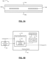
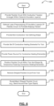
FIGS. 1A-1B are an end or cross-sectional view of an example flexible circuit (FC) and a functional block diagram of an example shaping system for an unshaped FC according to some implementations of the present disclosure; -
FIGS. 2A-2B are cross-sectional or end views of a pre-processed FC having a portion of the insulation layer(s) removed to further promote shaping according to some implementations of the present disclosure; -
FIGS. 3A-3B are perspective and end or cross-sectional views of a tool having heating elements therein and configured for triangular waveform shaping of a portion of an FC according to some implementations of the present disclosure; -
FIGS. 4A-4B are views of example FCs having triangular waveform shaped portions using the tool ofFIG. 3 and routing/attachment thereof around a pole-type object according to some implementations of the present disclosure; -
FIGS. 5A-5B are views of example FCs having sinusoidal waveform shaped portions according to some implementations of the present disclosure; and -
FIG. 6 is a flow diagram of an example method of shaping a portion of an FC, such as by providing and using the above-mentioned shaping system and tool/heating element(s), according to some implementations of the present disclosure. - As previously discussed, slits in insulation material(s) between conductive circuit trace(s) of a flexible circuit (FC) can be formed to increase flexibility for routing and attachment. More specifically, FCs are often slit, cut, singulated, or otherwise separated, typically through their full or entire thickness and longitudinally, to allow FC assemblies to be easily bent, gathered, or twisted in a specific area of the FC. These conventional FC separation methods increases risk of FC damage by producing individual FC "catch points" and reducing the FC assembly tensile strength to a tensile strength of a single conductive circuit (plus insulation). Such slits, therefore, tend to tear further than intended over time. In addition, full singulation or separation often results in damage over time, especially after repetitive routing (e.g., during or after electrified vehicle electrical system maintenance). Thus, while these conventional FC processing systems do work well for their intended purpose, there exists an opportunity for improvement in the relevant art.
- Accordingly, improved systems and methods for shaping portions of FCs are presented herein. As opposed to fully singulating or separating (e.g., cutting) the FC portion into a plurality of distinct portions each having a conductive circuit trace within insulation, the systems and methods herein utilize a unique tool having conductive heating elements therein that generate heat energy to shape the FC portion (i.e., to temporarily make the insulation layer(s) of the FC portion pliable or shapable). The resulting shaped FC does not suffer from the permanent slits/cuts of conventional techniques, which could result in further tearing and/or damage to the conductive circuit traces. The shaped FC is easily routable and attachable (e.g., bendable around a pole-type object) in a tight/crowded environment, such as an electrical system of an electrified vehicle (EV).
- Referring now to
FIGS. 1A-1B , an end or cross-sectional view of anexample FC 100 and a functional block diagram of anexample system 150 for shaping a portion of theFC 100 according to some implementations of the present disclosure are illustrated. InFIG. 1A , theFC 100 comprises a set of one or moreconductive traces 108 formed of a conductive material (copper, aluminum, etc.) and arranged substantially parallel to each other lengthwise and within one or more dielectric or insulation layers 104. As shown, theFC 100 comprises twoinsulation layers FC 100 could also include only a single dielectric or insulation layer 104. Each insulation layer is formed of a non-conductive laminate or thermoplastic material (e.g., a thermoplastic polymer resin), such as, but not limited to, polyethylene naphthalate (PEN) and polyethylene terephthalate (PET). - Referring now to
FIG. 1B and with continued reference toFIG. 1A , the shaping process, as performed byexample shaping system 150 and described more fully described below, generally involves mechanically folding or forming and materially resetting (via heat) the insulation layer(s) 104 incorporating a longitudinal or angular shape (e.g., a triangular or sinusoidal waveform) that allows theFC 100 to be collapsed or "pinched" in specific areas or sections without damage. The heat is applied at the bend or crease point along the length of the fold area to set the plastic and maintain the bend position during the cycle of folding or bending theFC 100. The temperature is dependent on the material(s) utilized for the insulation layer(s) 104. Thickness of material in the bend or crease may increase or decrease retention of the fold. Optionally, a cover or base film and/or an adhesive in the bend or crease could be removed without causing a cut edge in the insulation layer(s) 104 (retaining at least one layer of cover or base film to maintain FC stability). Depending on the amplitude, frequency, and angle of the fold pattern, theFC 100 can be shaped to meet electrified vehicle routing and attachment requirements while maintaining the full strength of theFC 100. - Referring now to
FIGS. 3A-3B and with continued reference toFIG. 1B , theshaping system 150 comprises anon-conductive tool second tool portions tool second tool portions living hinge 316 to provide clearance in avertical direction 320 for insertion of theFC 100 therebetween. It will be appreciated that thetool FC 100, such as insertion via an end and pressure/rolling theFC 100 therebetween the first andsecond tool portions - The
tool 154 also comprises a set ofconductive heating elements second tool portions heating elements power source 162, such as a battery or battery system. In some implementations, thepower source 162 is a battery/battery system such that theshaping system 150 is mobile (e.g., a handheld unit), which could be preferable due to increased flexibility for installation. It will be appreciated that thepower source 162 could also be a stationary power source, such as a traditional wall outlet. In some implementations, theshaping system 150 further comprises anoutput device 170 configured to generate an output (audio, visual, tactile, or some combination thereof) indicative of a status. For example, theoutput device 170 could illuminate a light and/or produce an audible noise when the shaping process is complete (e.g., when theconductive heating elements - Referring now to
FIGS. 2A-2B and with continued reference to the FIGS. discussed above, theshaping system 150 could optionally include or be associated with a laser processing orpre-processing system 166. Thislaser processing system 166 could be optionally used for laser processing of the unshaped FC prior to its insertion/shaping by theshaping system 150. For example, atop portion 204a (e.g., a slit) of both first andsecond insulation layers laser processing system 166 and the shaped orpre-processed FC 200a could then be fed to theshaping system 150. Alternatively, for example, abottom portion 204b (e.g., a slit) of both the first andsecond insulation layers laser processing system 166 and the shaped orpre-processed FC 200b could then be fed to theshaping system 150. This optional pre-processing could further assist in the formation/shaping of theFC 100, such as, for example only,FCs 100 having thicker or multiple insulation layers 104. - Referring now to
FIGS. 4A-4B and with continued reference toFIGS. 3A-3B , views of anexample FC 400 having triangular waveform shaped portions using the tool ofFIGS. 3A-3B according to some implementations of the present disclosure are illustrated. As previously discussed, one potential shape is a triangular waveform shape defining a series of peaks and valleys relative to the first andsecond tool portions FIG. 3A , eachconductive heating element second tool portions conductive heating elements conductive heating elements 158 have different lengths such that the shaping achieves different widths of bends/folds in at least some of the set of insulation layers. In addition, only a portion of the length of the FC could be shaped/processed as shown inFIGS. 4A-4B . Of theentire FC 400, afirst portion 404 is not processed/shaped and asecond portion 408 is processed/shaped, with a transitional or bunchedportion 412 therebetween. For example, only a portion of theFC 400 could be processed/shaped at a desired length point relative to an installation or routing feature, such as a pole-shapedobject 420 as shown inFIG. 4B . As can be seen, the processed/shapedportion 408 easily bends around the pole-shapedobject 420 atlength point 416 to mitigate or prevent damage to the FC 400 (e.g., increased flexibility or bendability in the x-direction). - Referring now to
FIGS. 5A-5B and with continued reference to the previous FIGS., views of anotherexample FC 500 having sinusoidal waveform shapedportions 504 using a different (but similar) tool as shown inFIGS. 3A-3B according to some implementations of the present disclosure are illustrated. The tool (not shown) to form/shape thesinusoidal waveform shape 504 as shown would be similar toFIGS. 3A-3B but would be sinusoidal rather than triangular, with, for example, conductive heating elements arranged in similar locations along the waveform shape 504 (e.g., peaks/valleys). As shown inFIG. 5A ,multiple insulation layers waveform shape 504. One primary benefit or purpose of the configuration of FC 500 (longitudinally extending sinusoidal or "wavy" undulations) is the stiffening of theFC specific sections 524 along its length (seeFIG. 5B , with intermediate/transitionary bunched portion 528). While a regular/repeating sinusoidal waveform shape is illustrated, it will be appreciated that any suitable wavy undulating shape could be utilized to achieve the desired stiffening. - Referring now to
FIG. 6 , a flow diagram of an example method 600 of shaping a portion of an FC using a system or tool/heating element(s) according to some implementations of the present disclosure is illustrated. At 604, an FC is provided with conductive trace(s) disposed between dielectric or insulation layer(s). At 608, optional laser preprocessing is performed to remove portion(s) of the insulation layer(s) to further promote or assist with the subsequent processing/shaping. At 612, a non-conductive tool defining a shape (triangular, sinusoidal, etc.) is provided. At 616, conductive heating element(s) are provided, such as within portions of the tool. At 620, a power source (stationary or mobile, such as a battery pack/system) is provided to selectively power the heating element(s). At 624, the FC is positioned within or relative to the tool and subsequently shaped by temporarily powering the heating element(s) using the powers source (e.g., until an end/complete indication is output or generated by an output device). At 628, the final processed/shaped FC is removed from the tool and then routed/attached in a desired environment, such as bending around a pole-type object in a vehicle electrical system. The method 600 then ends or returns to 604 for one or more additional cycles. - Example embodiments are provided so that this disclosure will be thorough and will fully convey the scope to those who are skilled in the art. Numerous specific details are set forth such as examples of specific components, devices, and methods, to provide a thorough understanding of embodiments of the present disclosure. It will be apparent to those skilled in the art that specific details need not be employed, that example embodiments may be embodied in many different forms and that neither should be construed to limit the scope of the disclosure. In some example embodiments, well-known procedures, well-known device structures, and well-known technologies are not described in detail.
- The terminology used herein is for the purpose of describing particular example embodiments only and is not intended to be limiting. As used herein, the singular forms "a," "an," and "the" may be intended to include the plural forms as well, unless the context clearly indicates otherwise. The term "and/or" includes any and all combinations of one or more of the associated listed items. The terms "comprises," "comprising," "including," and "having," are inclusive and therefore specify the presence of stated features, integers, steps, operations, elements, and/or components, but do not preclude the presence or addition of one or more other features, integers, steps, operations, elements, components, and/or groups thereof. The method steps, processes, and operations described herein are not to be construed as necessarily requiring their performance in the particular order discussed or illustrated, unless specifically identified as an order of performance. It is also to be understood that additional or alternative steps may be taken.
- Although the terms first, second, third, etc. may be used herein to describe various elements, components, regions, layers and/or sections, these elements, components, regions, layers and/or sections should not be limited by these terms. These terms may be only used to distinguish one element, component, region, layer or section from another region, layer or section. Terms such as "first," "second," and other numerical terms when used herein do not imply a sequence or order unless clearly indicated by the context. Thus, a first element, component, region, layer or section discussed below could be termed a second element, component, region, layer or section without departing from the teachings of the example embodiments.
- Some portions of the above description present the techniques described herein in terms of algorithms and symbolic representations of operations on information. These algorithmic descriptions and representations are the means used by those skilled in the data processing arts to most effectively convey the substance of their work to others skilled in the art. These operations, while described functionally or logically, are understood to be implemented by computer programs. Furthermore, it has also proven convenient at times to refer to these arrangements of operations as modules or by functional names, without loss of generality.
- The foregoing description of the embodiments has been provided for purposes of illustration and description. It is not intended to be exhaustive or to limit the disclosure. Individual elements or features of a particular embodiment are generally not limited to that particular embodiment, but, where applicable, are interchangeable and can be used in a selected embodiment, even if not specifically shown or described. The same may also be varied in many ways. Such variations are not to be regarded as a departure from the disclosure, and all such modifications are intended to be included within the scope of the disclosure.
- In the following, preferred embodiments are described to facilitate understanding:
- Embodiment 1. A system for shaping a flexible circuit (FC) (100, 400, 500, 520) including a set of conductive traces disposed within a set of insulation layers (104), the system comprising:
- a non-conductive tool (154, 300) defining complimentary first and second tool portions (304a, 304b) and a shape therebetween, the tool (154, 300) being configured to receive a portion of the FC (100, 400, 500, 520) between the first and second tool (154, 300) portions (304a, 304b);
- a set of conductive heating elements (158, 308a, 308b) arranged substantially in parallel with each other and disposed within the first and second tool (154, 300) portions (304a, 304b); and
- a power source (162) configured to provide power to the conductive heating elements (158, 308a, 308b) causing the conductive heating elements (158, 308a, 308b) to generate heat energy to shape the FC portion without removing any of the FC portion.
- Embodiment 2. The system of embodiment 1, wherein the shape is a waveform shape (504) defining a series of peaks and valleys relative to the first and second tool portions (304a, 304b).
- Embodiment 3. The system of embodiment 2, wherein each conductive heating element is substantially aligned with a respective peak-valley pair in one of the first and second tool (154, 300) portions (304a, 304b) corresponding to a peak side of the respective peak-valley pair.
- Embodiment 4. The system of embodiment 2, wherein the waveform shape (504) is a triangular waveform shape (312, 504) for increasing flexibility or bendability of the FC (100, 400, 500, 520) perpendicular to its length.
-
Embodiment 5. The system of embodiment 2, wherein the waveform shape (504) is a sinusoidal waveform shape (504) for increasing rigidity or stiffness of the FC (100, 400, 500, 520) along its length. - Embodiment 6. The system of embodiment 1, wherein the first and second tool (154, 300) portions (304a, 304b) are arranged in a clamp configuration joined on one respective side by a hinge member and moveable relative to each other such that:
- when the first and second tool portions (304a, 304b) are separated from each other in an open position, the FC (100, 400, 500, 520) portion is positionable therein; and
- when the first and second tool portions (304a, 304b) are proximate to each other in a closed position, the FC (100, 400, 500, 520) portion is secured therein for shaping.
- Embodiment 7. The system of embodiment 1, wherein the first and second portions are fixed relative to each other defining a slot or gap therebetween for insertion and shaping of the FC portion therebetween.
- Embodiment 8. The system of embodiment 1, wherein some conductive heating elements of the set of conductive heating elements (158, 308a, 308b) have different lengths such that the shaping achieves different widths of bends/folds in at least some of the set of insulation layers (104).
- Embodiment 9. The system of embodiment 1, further comprising a laser processing system (166) configured to pre-process the FC portion to etch or remove a portion of the set of insulation layers (104) in an area of the FC portion to promote subsequent shaping.
- Embodiment 10. The system of embodiment 1, wherein the power source (162) is a battery system such that the system is movable to any desired position.
- Embodiment 11. The system of embodiment 1, further comprising an output device (170) configured to generate at least one of an audible, visual, and tactile output after a shaping period of providing power to the set of conductive elements to shape the FC portion, wherein the shaping period has a sufficient duration to complete the shaping of the FC portion.
- Embodiment 12. A method (600) of shaping a flexible circuit (FC) (100, 400, 500, 520) including a set of conductive traces disposed within a set of insulation layers (104), the method (600) comprising:
- providing a non-conductive tool (154, 300) defining complimentary first and second tool (154, 300) portions (304a, 304b) and a shape therebetween, the tool (154, 300) being configured to receive a portion of the FC (100, 400, 500, 520) between the first and second tool portions (304a, 304b);
- providing a set of conductive heating elements (158, 308a, 308b) arranged substantially in parallel with each other and disposed within the first and second tool (154, 300) portions (304a, 304b);
- providing a power source (162) configured to provide power to the conductive heating elements causing the conductive heating elements to generate heat energy;
- positioning the FC portion within the tool (154, 300); and
- providing power to the conductive heating elements to shape the FC portion without removing any of the FC portion.
- Embodiment 13. The method (600) of embodiment 12, further comprising:
- providing a laser processing system (166) configured to etch or remove a portion of the set of insulation layers (104) of the FC (100, 400, 500, 520); and
- pre-processing the FC portion with the laser processing system (166) to promote subsequent shaping.
- Embodiment 14. The method (600) of embodiment 12, further comprising:
- providing an output device (170) configured to generate at least one of an audible, visual, and tactile output; and
- actuating the output device (170) after a shaping period of providing power to the set of conductive elements to shape the FC portion, wherein the shaping period has a sufficient duration to complete the shaping of the FC portion.
- Embodiment 15. A flexible circuit (FC) (100, 400, 500, 520), comprising:
- a set of one or more insulation layers (104); and
- a set of conductive circuit traces disposed within the set of one or more insulation layers (104), wherein the sets of insulation layers (104) and conductive circuit traces collectively define a cross-sectional shape of the FC (100, 400, 500, 520) and wherein the FC cross-sectional shape is a waveform shape (504) to provide a desired alteration in flexibility/rigidity of the FC (100, 400, 500, 520) along one of its axes.
Claims (15)
- A system for shaping a flexible circuit (FC) (100, 400, 500, 520) including a set of conductive traces disposed within a set of insulation layers (104), the system comprising:a non-conductive tool (154, 300) defining complimentary first and second tool portions (304a, 304b) and a shape therebetween, the tool (154, 300) being configured to receive a portion of the FC (100, 400, 500, 520) between the first and second tool (154, 300) portions (304a, 304b);a set of conductive heating elements (158, 308a, 308b) arranged substantially in parallel with each other and disposed within the first and second tool (154, 300) portions (304a, 304b); anda power source (162) configured to provide power to the conductive heating elements (158, 308a, 308b) causing the conductive heating elements (158, 308a, 308b) to generate heat energy to shape the FC portion without removing any of the FC portion.
- The system of claim 1, wherein the shape is a waveform shape (504) defining a series of peaks and valleys relative to the first and second tool portions (304a, 304b).
- The system of claim 2, wherein each conductive heating element is substantially aligned with a respective peak-valley pair in one of the first and second tool (154, 300) portions (304a, 304b) corresponding to a peak side of the respective peak-valley pair.
- The system of claim 2 or 3, wherein the waveform shape (504) is a triangular waveform shape (312, 504) for increasing flexibility or bendability of the FC (100, 400, 500, 520) perpendicular to its length.
- The system of any one of claims 2 to 4, wherein the waveform shape (504) is a sinusoidal waveform shape (504) for increasing rigidity or stiffness of the FC (100, 400, 500, 520) along its length.
- The system of any one of the preceding claims, wherein the first and second tool (154, 300) portions (304a, 304b) are arranged in a clamp configuration joined on one respective side by a hinge member and moveable relative to each other such that:when the first and second tool portions (304a, 304b) are separated from each other in an open position, the FC (100, 400, 500, 520) portion is positionable therein; andwhen the first and second tool portions (304a, 304b) are proximate to each other in a closed position, the FC (100, 400, 500, 520) portion is secured therein for shaping.
- The system of any one of the preceding claims, wherein the first and second portions are fixed relative to each other defining a slot or gap therebetween for insertion and shaping of the FC portion therebetween.
- The system of any one of the preceding claims, wherein some conductive heating elements of the set of conductive heating elements (158, 308a, 308b) have different lengths such that the shaping achieves different widths of bends/folds in at least some of the set of insulation layers (104).
- The system of any one of the preceding claims, further comprising a laser processing system (166) configured to pre-process the FC portion to etch or remove a portion of the set of insulation layers (104) in an area of the FC portion to promote subsequent shaping.
- The system of any one of the preceding claims, wherein the power source (162) is a battery system such that the system is movable to any desired position.
- The system of any one of the preceding claims, further comprising an output device (170) configured to generate at least one of an audible, visual, and tactile output after a shaping period of providing power to the set of conductive elements to shape the FC portion, wherein the shaping period has a sufficient duration to complete the shaping of the FC portion.
- A method (600) of shaping a flexible circuit (FC) (100, 400, 500, 520) including a set of conductive traces disposed within a set of insulation layers (104), the method (600) comprising:providing a non-conductive tool (154, 300) defining complimentary first and second tool (154, 300) portions (304a, 304b) and a shape therebetween, the tool (154, 300) being configured to receive a portion of the FC (100, 400, 500, 520) between the first and second tool portions (304a, 304b);providing a set of conductive heating elements (158, 308a, 308b) arranged substantially in parallel with each other and disposed within the first and second tool (154, 300) portions (304a, 304b);providing a power source (162) configured to provide power to the conductive heating elements causing the conductive heating elements to generate heat energy;positioning the FC portion within the tool (154, 300); andproviding power to the conductive heating elements to shape the FC portion without removing any of the FC portion.
- The method (600) of claim 12, further comprising:providing a laser processing system (166) configured to etch or remove a portion of the set of insulation layers (104) of the FC (100, 400, 500, 520); andpre-processing the FC portion with the laser processing system (166) to promote subsequent shaping.
- The method (600) of claim 12 or 13, further comprising:providing an output device (170) configured to generate at least one of an audible, visual, and tactile output; andactuating the output device (170) after a shaping period of providing power to the set of conductive elements to shape the FC portion, wherein the shaping period has a sufficient duration to complete the shaping of the FC portion.
- A flexible circuit (FC) (100, 400, 500, 520), comprising:a set of one or more insulation layers (104); anda set of conductive circuit traces disposed within the set of one or more insulation layers (104), wherein the sets of insulation layers (104) and conductive circuit traces collectively define a cross-sectional shape of the FC (100, 400, 500, 520) and wherein the FC cross-sectional shape is a waveform shape (504) to provide a desired alteration in flexibility/rigidity of the FC (100, 400, 500, 520) along one of its axes.
Applications Claiming Priority (1)
| Application Number | Priority Date | Filing Date | Title |
|---|---|---|---|
| US17/889,473 US12156342B2 (en) | 2022-08-17 | 2022-08-17 | Systems and methods for shaping flexible circuits to improve routing and attachment |
Publications (2)
| Publication Number | Publication Date |
|---|---|
| EP4326011A2 true EP4326011A2 (en) | 2024-02-21 |
| EP4326011A3 EP4326011A3 (en) | 2024-02-28 |
Family
ID=86895874
Family Applications (1)
| Application Number | Title | Priority Date | Filing Date |
|---|---|---|---|
| EP23179564.2A Pending EP4326011A3 (en) | 2022-08-17 | 2023-06-15 | Systems and methods for shaping flexible circuits to improve routing and attachment |
Country Status (3)
| Country | Link |
|---|---|
| US (2) | US12156342B2 (en) |
| EP (1) | EP4326011A3 (en) |
| CN (1) | CN117596776A (en) |
Family Cites Families (5)
| Publication number | Priority date | Publication date | Assignee | Title |
|---|---|---|---|---|
| US5097101A (en) | 1991-02-05 | 1992-03-17 | Tektronix, Inc. | Method of forming a conductive contact bump on a flexible substrate and a flexible substrate |
| US5219640A (en) | 1991-02-08 | 1993-06-15 | Rogers Corporation | Flexible circuit having flexing section of reduced stiffness, and method of manufacture thereof |
| US8338278B2 (en) * | 2006-12-04 | 2012-12-25 | Semiconductor Energy Laboratory Co., Ltd. | Method of manufacturing semiconductor device with crystallized semiconductor film |
| JP5323668B2 (en) | 2009-12-24 | 2013-10-23 | 日本メクトロン株式会社 | LIGHTING DEVICE AND MANUFACTURING METHOD THEREOF |
| US20220062621A1 (en) * | 2015-02-24 | 2022-03-03 | Elira, Inc. | Electrical Stimulation-Based Weight Management System |
-
2022
- 2022-08-17 US US17/889,473 patent/US12156342B2/en active Active
-
2023
- 2023-06-15 EP EP23179564.2A patent/EP4326011A3/en active Pending
- 2023-07-05 CN CN202310819760.4A patent/CN117596776A/en active Pending
-
2024
- 2024-11-07 US US18/939,692 patent/US20250063670A1/en active Pending
Also Published As
| Publication number | Publication date |
|---|---|
| EP4326011A3 (en) | 2024-02-28 |
| CN117596776A (en) | 2024-02-23 |
| US20240064908A1 (en) | 2024-02-22 |
| US20250063670A1 (en) | 2025-02-20 |
| US12156342B2 (en) | 2024-11-26 |
Similar Documents
| Publication | Publication Date | Title |
|---|---|---|
| EP0971370B1 (en) | Cable and method of manufacturing it | |
| CN107852843B (en) | Electromagnetic shielding member and wiring device with shielding member | |
| EP2736133A1 (en) | Wire harness | |
| US10158266B2 (en) | Motor having interphase insulation sheet mounted thereon | |
| CN103329380A (en) | Cable with terminal, and manufacturing method and corrosion-resistant member for cable with terminal | |
| CN104245253A (en) | Blade set for hair cutting appliance and method for its manufacture | |
| EP4326011A2 (en) | Systems and methods for shaping flexible circuits to improve routing and attachment | |
| KR20040111718A (en) | Low-profile protective sheath with corrugations | |
| JP2010538594A (en) | Device for guiding conductors, hoses, etc. | |
| JP5977050B2 (en) | Insulating member manufacturing method and insulating member manufacturing apparatus | |
| JP2012023888A (en) | Bus bar manufacturing method | |
| JP6996639B2 (en) | Wiring member and manufacturing method of wiring member | |
| US20150068263A1 (en) | Method and device for manufacturing a corrugated metal pipe | |
| JP6939503B2 (en) | How to cut a flat conductor | |
| JP5984341B2 (en) | Wire harness | |
| CN107210093B (en) | wire module | |
| CN109526236B (en) | Electric planar conductor device and method of manufacturing an electric planar conductor device | |
| JP3694207B2 (en) | Method for manufacturing tape electric wire with terminal and method for manufacturing wire harness | |
| US11430582B2 (en) | Routing material and manufacturing method thereof | |
| KR20190097194A (en) | Electrically conductive film | |
| CN1280901A (en) | Scissors | |
| JP6065830B2 (en) | Protector, wire module, and protector manufacturing method | |
| JPH10512438A (en) | Vertical stators for linear motors and lamination bundles for manufacturing vertical stators | |
| US20240363970A1 (en) | Bus bar member and manufacturing method of bus bar member | |
| JP3706199B2 (en) | Wire harness vacuum forming method and wire harness formed by this method |
Legal Events
| Date | Code | Title | Description |
|---|---|---|---|
| PUAI | Public reference made under article 153(3) epc to a published international application that has entered the european phase |
Free format text: ORIGINAL CODE: 0009012 |
|
| STAA | Information on the status of an ep patent application or granted ep patent |
Free format text: STATUS: THE APPLICATION HAS BEEN PUBLISHED |
|
| PUAL | Search report despatched |
Free format text: ORIGINAL CODE: 0009013 |
|
| AK | Designated contracting states |
Kind code of ref document: A2 Designated state(s): AL AT BE BG CH CY CZ DE DK EE ES FI FR GB GR HR HU IE IS IT LI LT LU LV MC ME MK MT NL NO PL PT RO RS SE SI SK SM TR |
|
| AK | Designated contracting states |
Kind code of ref document: A3 Designated state(s): AL AT BE BG CH CY CZ DE DK EE ES FI FR GB GR HR HU IE IS IT LI LT LU LV MC ME MK MT NL NO PL PT RO RS SE SI SK SM TR |
|
| RIC1 | Information provided on ipc code assigned before grant |
Ipc: H05K 1/03 20060101ALN20240119BHEP Ipc: H05K 3/00 20060101ALI20240119BHEP Ipc: H05K 1/02 20060101AFI20240119BHEP |
|
| RAP1 | Party data changed (applicant data changed or rights of an application transferred) |
Owner name: APTIV TECHNOLOGIES AG |
|
| STAA | Information on the status of an ep patent application or granted ep patent |
Free format text: STATUS: REQUEST FOR EXAMINATION WAS MADE |
|
| RAP3 | Party data changed (applicant data changed or rights of an application transferred) |
Owner name: APTIV TECHNOLOGIES AG |
|
| 17P | Request for examination filed |
Effective date: 20240828 |
|
| RBV | Designated contracting states (corrected) |
Designated state(s): AL AT BE BG CH CY CZ DE DK EE ES FI FR GB GR HR HU IE IS IT LI LT LU LV MC ME MK MT NL NO PL PT RO RS SE SI SK SM TR |