EP4325640A2 - Battery apparatus - Google Patents
Battery apparatus Download PDFInfo
- Publication number
- EP4325640A2 EP4325640A2 EP23155948.5A EP23155948A EP4325640A2 EP 4325640 A2 EP4325640 A2 EP 4325640A2 EP 23155948 A EP23155948 A EP 23155948A EP 4325640 A2 EP4325640 A2 EP 4325640A2
- Authority
- EP
- European Patent Office
- Prior art keywords
- insulating film
- battery
- batteries
- box cover
- disclosure
- Prior art date
- Legal status (The legal status is an assumption and is not a legal conclusion. Google has not performed a legal analysis and makes no representation as to the accuracy of the status listed.)
- Withdrawn
Links
Images



Classifications
-
- H—ELECTRICITY
- H01—ELECTRIC ELEMENTS
- H01M—PROCESSES OR MEANS, e.g. BATTERIES, FOR THE DIRECT CONVERSION OF CHEMICAL ENERGY INTO ELECTRICAL ENERGY
- H01M50/00—Constructional details or processes of manufacture of the non-active parts of electrochemical cells other than fuel cells, e.g. hybrid cells
- H01M50/20—Mountings; Secondary casings or frames; Racks, modules or packs; Suspension devices; Shock absorbers; Transport or carrying devices; Holders
- H01M50/244—Secondary casings; Racks; Suspension devices; Carrying devices; Holders characterised by their mounting method
-
- H—ELECTRICITY
- H01—ELECTRIC ELEMENTS
- H01M—PROCESSES OR MEANS, e.g. BATTERIES, FOR THE DIRECT CONVERSION OF CHEMICAL ENERGY INTO ELECTRICAL ENERGY
- H01M50/00—Constructional details or processes of manufacture of the non-active parts of electrochemical cells other than fuel cells, e.g. hybrid cells
- H01M50/20—Mountings; Secondary casings or frames; Racks, modules or packs; Suspension devices; Shock absorbers; Transport or carrying devices; Holders
- H01M50/233—Mountings; Secondary casings or frames; Racks, modules or packs; Suspension devices; Shock absorbers; Transport or carrying devices; Holders characterised by physical properties of casings or racks, e.g. dimensions
- H01M50/242—Mountings; Secondary casings or frames; Racks, modules or packs; Suspension devices; Shock absorbers; Transport or carrying devices; Holders characterised by physical properties of casings or racks, e.g. dimensions adapted for protecting batteries against vibrations, collision impact or swelling
-
- H—ELECTRICITY
- H01—ELECTRIC ELEMENTS
- H01M—PROCESSES OR MEANS, e.g. BATTERIES, FOR THE DIRECT CONVERSION OF CHEMICAL ENERGY INTO ELECTRICAL ENERGY
- H01M50/00—Constructional details or processes of manufacture of the non-active parts of electrochemical cells other than fuel cells, e.g. hybrid cells
- H01M50/20—Mountings; Secondary casings or frames; Racks, modules or packs; Suspension devices; Shock absorbers; Transport or carrying devices; Holders
- H01M50/204—Racks, modules or packs for multiple batteries or multiple cells
- H01M50/207—Racks, modules or packs for multiple batteries or multiple cells characterised by their shape
- H01M50/209—Racks, modules or packs for multiple batteries or multiple cells characterised by their shape adapted for prismatic or rectangular cells
-
- H—ELECTRICITY
- H01—ELECTRIC ELEMENTS
- H01M—PROCESSES OR MEANS, e.g. BATTERIES, FOR THE DIRECT CONVERSION OF CHEMICAL ENERGY INTO ELECTRICAL ENERGY
- H01M10/00—Secondary cells; Manufacture thereof
- H01M10/60—Heating or cooling; Temperature control
- H01M10/65—Means for temperature control structurally associated with the cells
- H01M10/658—Means for temperature control structurally associated with the cells by thermal insulation or shielding
-
- H—ELECTRICITY
- H01—ELECTRIC ELEMENTS
- H01M—PROCESSES OR MEANS, e.g. BATTERIES, FOR THE DIRECT CONVERSION OF CHEMICAL ENERGY INTO ELECTRICAL ENERGY
- H01M50/00—Constructional details or processes of manufacture of the non-active parts of electrochemical cells other than fuel cells, e.g. hybrid cells
- H01M50/10—Primary casings; Jackets or wrappings
- H01M50/147—Lids or covers
- H01M50/166—Lids or covers characterised by the methods of assembling casings with lids
- H01M50/171—Lids or covers characterised by the methods of assembling casings with lids using adhesives or sealing agents
-
- H—ELECTRICITY
- H01—ELECTRIC ELEMENTS
- H01M—PROCESSES OR MEANS, e.g. BATTERIES, FOR THE DIRECT CONVERSION OF CHEMICAL ENERGY INTO ELECTRICAL ENERGY
- H01M50/00—Constructional details or processes of manufacture of the non-active parts of electrochemical cells other than fuel cells, e.g. hybrid cells
- H01M50/20—Mountings; Secondary casings or frames; Racks, modules or packs; Suspension devices; Shock absorbers; Transport or carrying devices; Holders
- H01M50/204—Racks, modules or packs for multiple batteries or multiple cells
-
- H—ELECTRICITY
- H01—ELECTRIC ELEMENTS
- H01M—PROCESSES OR MEANS, e.g. BATTERIES, FOR THE DIRECT CONVERSION OF CHEMICAL ENERGY INTO ELECTRICAL ENERGY
- H01M50/00—Constructional details or processes of manufacture of the non-active parts of electrochemical cells other than fuel cells, e.g. hybrid cells
- H01M50/20—Mountings; Secondary casings or frames; Racks, modules or packs; Suspension devices; Shock absorbers; Transport or carrying devices; Holders
- H01M50/233—Mountings; Secondary casings or frames; Racks, modules or packs; Suspension devices; Shock absorbers; Transport or carrying devices; Holders characterised by physical properties of casings or racks, e.g. dimensions
- H01M50/24—Mountings; Secondary casings or frames; Racks, modules or packs; Suspension devices; Shock absorbers; Transport or carrying devices; Holders characterised by physical properties of casings or racks, e.g. dimensions adapted for protecting batteries from their environment, e.g. from corrosion
-
- H—ELECTRICITY
- H01—ELECTRIC ELEMENTS
- H01M—PROCESSES OR MEANS, e.g. BATTERIES, FOR THE DIRECT CONVERSION OF CHEMICAL ENERGY INTO ELECTRICAL ENERGY
- H01M50/00—Constructional details or processes of manufacture of the non-active parts of electrochemical cells other than fuel cells, e.g. hybrid cells
- H01M50/20—Mountings; Secondary casings or frames; Racks, modules or packs; Suspension devices; Shock absorbers; Transport or carrying devices; Holders
- H01M50/249—Mountings; Secondary casings or frames; Racks, modules or packs; Suspension devices; Shock absorbers; Transport or carrying devices; Holders specially adapted for aircraft or vehicles, e.g. cars or trains
-
- H—ELECTRICITY
- H01—ELECTRIC ELEMENTS
- H01M—PROCESSES OR MEANS, e.g. BATTERIES, FOR THE DIRECT CONVERSION OF CHEMICAL ENERGY INTO ELECTRICAL ENERGY
- H01M50/00—Constructional details or processes of manufacture of the non-active parts of electrochemical cells other than fuel cells, e.g. hybrid cells
- H01M50/20—Mountings; Secondary casings or frames; Racks, modules or packs; Suspension devices; Shock absorbers; Transport or carrying devices; Holders
- H01M50/289—Mountings; Secondary casings or frames; Racks, modules or packs; Suspension devices; Shock absorbers; Transport or carrying devices; Holders characterised by spacing elements or positioning means within frames, racks or packs
- H01M50/291—Mountings; Secondary casings or frames; Racks, modules or packs; Suspension devices; Shock absorbers; Transport or carrying devices; Holders characterised by spacing elements or positioning means within frames, racks or packs characterised by their shape
-
- H—ELECTRICITY
- H01—ELECTRIC ELEMENTS
- H01M—PROCESSES OR MEANS, e.g. BATTERIES, FOR THE DIRECT CONVERSION OF CHEMICAL ENERGY INTO ELECTRICAL ENERGY
- H01M50/00—Constructional details or processes of manufacture of the non-active parts of electrochemical cells other than fuel cells, e.g. hybrid cells
- H01M50/20—Mountings; Secondary casings or frames; Racks, modules or packs; Suspension devices; Shock absorbers; Transport or carrying devices; Holders
- H01M50/289—Mountings; Secondary casings or frames; Racks, modules or packs; Suspension devices; Shock absorbers; Transport or carrying devices; Holders characterised by spacing elements or positioning means within frames, racks or packs
- H01M50/293—Mountings; Secondary casings or frames; Racks, modules or packs; Suspension devices; Shock absorbers; Transport or carrying devices; Holders characterised by spacing elements or positioning means within frames, racks or packs characterised by the material
-
- H—ELECTRICITY
- H01—ELECTRIC ELEMENTS
- H01M—PROCESSES OR MEANS, e.g. BATTERIES, FOR THE DIRECT CONVERSION OF CHEMICAL ENERGY INTO ELECTRICAL ENERGY
- H01M50/00—Constructional details or processes of manufacture of the non-active parts of electrochemical cells other than fuel cells, e.g. hybrid cells
- H01M50/50—Current conducting connections for cells or batteries
- H01M50/543—Terminals
- H01M50/547—Terminals characterised by the disposition of the terminals on the cells
-
- H—ELECTRICITY
- H01—ELECTRIC ELEMENTS
- H01M—PROCESSES OR MEANS, e.g. BATTERIES, FOR THE DIRECT CONVERSION OF CHEMICAL ENERGY INTO ELECTRICAL ENERGY
- H01M50/00—Constructional details or processes of manufacture of the non-active parts of electrochemical cells other than fuel cells, e.g. hybrid cells
- H01M50/50—Current conducting connections for cells or batteries
- H01M50/572—Means for preventing undesired use or discharge
- H01M50/584—Means for preventing undesired use or discharge for preventing incorrect connections inside or outside the batteries
- H01M50/588—Means for preventing undesired use or discharge for preventing incorrect connections inside or outside the batteries outside the batteries, e.g. incorrect connections of terminals or busbars
-
- H—ELECTRICITY
- H01—ELECTRIC ELEMENTS
- H01M—PROCESSES OR MEANS, e.g. BATTERIES, FOR THE DIRECT CONVERSION OF CHEMICAL ENERGY INTO ELECTRICAL ENERGY
- H01M50/00—Constructional details or processes of manufacture of the non-active parts of electrochemical cells other than fuel cells, e.g. hybrid cells
- H01M50/50—Current conducting connections for cells or batteries
- H01M50/572—Means for preventing undesired use or discharge
- H01M50/584—Means for preventing undesired use or discharge for preventing incorrect connections inside or outside the batteries
- H01M50/59—Means for preventing undesired use or discharge for preventing incorrect connections inside or outside the batteries characterised by the protection means
- H01M50/593—Spacers; Insulating plates
Definitions
- the disclosure relates to the technical field of batteries, and in particular, relates to a battery apparatus.
- the disclosure provides a battery apparatus including a battery pack.
- the battery pack includes a plurality of batteries arranged in a first direction, terminal components of the batteries are located on other surfaces of the batteries except the top surfaces, and an insulating film is provided on a top portion of the battery pack.
- connection In particular, a reference to “the” object or “a” and “an” object is intended to denote also one of a possible plurality of such objects.
- the terms “connect”, “fix” should be broadly interpreted, for example, the term “connect” can be “fixedly connect”, “detachably connect”, “integrally connect”, “electrically connect” or “signal connect”.
- the term “connect” also can be “directly connect” or “indirectly connect via a medium”.
- FIG. 1 is a schematic three-dimensional view illustrating a structure of a battery apparatus according to disclosure.
- a vehicle-mounted battery is treated as an example of the battery apparatus provided by the disclosure. It is easy for a person having ordinary skill in the art to understand that, in order to apply the relevant design of the disclosure to other types of battery apparatuses, various modifications, additions, substitutions, deletions or other changes may be made to the following specific embodiments, and these changes still fall within the scope of the principle of the battery apparatus provided by the disclosure.
- a battery apparatus provided by the disclosure includes a box body 100 and a battery pack 200, the battery pack 200 is accommodated in the box body 100, and the battery pack 200 includes a plurality of batteries 210 arranged in a first direction X.
- FIG. 2 is a schematic three-dimensional exploded view illustrating the battery apparatus which embodies the principles of the disclosure.
- FIG. 3 is a schematic three-dimensional view illustrating part of the structure of the battery apparatus and specifically shows the three-dimensional structure of the combination of the battery pack 200 and an insulating film 400.
- FIG. 4 is a schematic three-dimensional view illustrating the structure of the batteries 210 of FIG. 2 .
- terminal components of the batteries 100 are located on other surfaces of the batteries 100 except the top surfaces.
- the terminal components of the battery 100 shown in FIG. 9 is located on the side of the battery 100 that is perpendicular to the first direction, that is, the "large surface" of the battery 100. Since the terminal components are not disposed on the top surface of the battery 100, a collecting structure (e.g., collecting circuit board) of the battery 100 connected to the terminal components is not disposed on a top portion of the battery 100. That is, the top portion of the battery 100 does not have a film material for covering the collecting structure. Based on the above, the insulating film 400 is provided on the top portion of the battery pack 200.
- the insulating film 400 when the batteries 210 swell and deform or when the battery apparatus vibrates and a box cover 300 deforms, the resulting contact between the battery pack 200 and the box cover 300 or other structures located above the battery pack 200 is prevented from occurring, and the potential safety hazard of the battery apparatus is thereby reduced.
- the insulating film is easier to form than the insulating plate, especially the larger the size, the more difficult it is to form the insulating plate.
- the thickness of the insulating film is thinner, so that the top portion space and weight of the battery apparatus are saved.
- the insulating film is made of a flexible material and thus can be easily pressed, so that less space is additionally occupied.
- the swelling direction of a battery is in the direction perpendicular to the large surface of the battery. If the top portion of the battery is provided with a terminal component, it means that the tab of the battery needs to be connected to the terminal component, and a specific gap is certain to be left between the top cover of the battery apparatus and the battery. Therefore, even if the battery swells, it may not directly contact the top cover and may not cause deformation of the top cover, so an additional insulating film is not required to be provided on the top portion of the battery to achieve insulation.
- the insulating film 400 may be a single-layered film structure. In some embodiments, the insulating film 400 may be a multi-layered film structure.
- the insulating film 400 and the battery pack 200 may be bonded by adhesive.
- the insulating film may deform to a certain extent.
- the insulating film 400 using the insulating film may deform and shrink.
- the deformation ability of the insulating plate is poor, so when the batteries 210 swell, it is easy to apply force on the insulating plate, resulting in failure of the connection between the insulating plate and the battery pack 200.
- the two ends of the battery pack 200 is the first direction X are provided with end portion structures.
- the end portion structures may be batteries 210 (i.e., the batteries 210 at the end portions of the battery pack 200 in the first direction X) or end plates 220 (at the end portions of the batteries 210 in the first direction X).
- the insulating film 400 may be adhesively bonded to at least two end portion structures of the battery pack 200. Through the above design, the insulating film 400 may span at least part of two batteries 210 at least.
- the batteries 210 swell for example, the "large surfaces” of the batteries 210 swell, and the “large surfaces” are the side surfaces of the batteries 210 perpendicular to the first direction X
- the insulating film 400 is pulled, and the deformation of the insulating film may absorb the aforementioned swelling force of the batteries 210.
- the battery apparatus provided by the disclosure further includes the box cover 300.
- the box cover 300 is located above the insulating film 400, that is, the insulating film 400 is located between the box cover 300 and the battery pack 200.
- the insulating film 400 is adhesively bonded to the box cover 300.
- the insulating film 400 and the box cover 300 are fixed by means of gluing, so that the insulating film 400 and the box cover 300 may be fixed together when the material is supplied, and the insulating film 400 may be covered on the battery pack 200 when the box cover 300 is assembled. Accordingly, the assembly of the battery apparatus may be made more convenient, and the process step of fixing the insulating film 400 to the battery pack 200 is omitted.
- the insulating film 400 may cover all the batteries 210 of the battery pack 200.
- the batteries 210 swell, for example, when the "large surfaces" of the batteries 210 swell, resulting in the formation of gaps between adjacent batteries 210 and the insulating film 400 is pulled, the swelling force of the batteries 210 may be absorbed through the deformation of the insulating film 400.
- the insulating film 400 may cover at least part of two adjacent batteries 210 of the battery pack 200 at least. Accordingly, the swelling force of the two adjacent batteries 210 may be absorbed at least through the deformation of the insulating film 400, which is not limited to this embodiment.
- FIG. 5 is a schematic three-dimensional exploded view illustrating part of the structure of the battery apparatus which embodies the principles of the disclosure according to another exemplary embodiment.
- the three-dimensional structures of the insulating film 400 and the battery pack 200 in a disassembled state are specifically shown.
- FIG. 6 is a local cross-sectional view schematically illustrating part of the structure of the battery apparatus shown in FIG. 5 .
- a first buffer layer 410 may be disposed between the insulating film 400 and the battery pack 200. That is, the insulating film 400 is supported and fixed on the top surface of the battery pack through the first buffer layer 410, and the insulating film 400 is not directly connected to the battery pack 200. That is, a gap is provided between a portion of the insulating film 400 where the first buffer layer 410 is not provided and the battery pack 200.
- the swelling gaps of the batteries 210 may be reserved, and support may be provided by the first buffer layer.
- the problems of noise generated during vibration and insulation failure caused by the contact of the battery pack 200 with the structure above it (e.g., the box cover 300 and the like) during collision are prevented from occurring.
- the top portions of the batteries 210 have flange structures 211 such as flange edges
- the insulating film 400 using the insulating film may be pierced by the flange structures 211. Therefore, the first buffer layer 410 may also protect the insulating film 400 from being pierced by the flange structures 211.
- the first buffer layer 410 may be a strip-shaped structure extending in a second direction Y, and the second direction Y is perpendicular to the first direction.
- the top portions of the batteries 210 have the flange structures 211 protruding towards the insulating film 400, such as but not limited to flange edges.
- the first buffer layer 410 may be disposed between the flange structures 211 of at least two adjacent batteries 210.
- the limiting function of the first buffer layer 410 may be achieved by the flange structures 211 of two adjacent batteries 210.
- the first buffer layer 410 and the insulating film 400 may be adhesively bonded.
- sine the first buffer layer 410 may deform to a certain extent, based on the design of the adhesive bonding between the first buffer layer 410 and the battery pack 200, when the batteries 210 swell and squeeze the first buffer layer 410, the first buffer layer 410 may deform and shrink. The failure of the connection between the first buffer layer 410 and the insulating film 400 caused by force application on the first buffer layer 410 when the batteries 210 swell is prevented from occurring.
- the material of the first buffer layer 410 is buffer foam.
- a plurality of first buffer layers 410 may be disposed between the insulating film 400 and the battery pack 200, and the first buffer layers 410 are arranged at intervals in the first direction X.
- the swelling gaps of the batteries 210 may be reserved, and multiple positions of the insulating film 400 may be further supported and protected.
- the battery apparatus further includes the box cover 300, and the box cover 300 is located above the insulating film 400.
- the box cover 300 may have a plurality of ribs 310 protruding towards the insulating film 400, and the ribs 310 may correspond to the first buffer layers 410 one-to-one.
- the structural strength of the box cover 300 may be further increased by the ribs 310.
- the ribs 310 are used to correspond to the first buffer layer 410, so that the first buffer layer 410 indirectly supports the ribs 310 through the insulating film 400, so that the box cover 300 is supported, and the box cover 300 is bonded to the battery pack 200.
- the box cover 300 is prevented from hitting the battery pack 200 during vibration, and noise is also prevented from being generated.
- FIG. 9 is a local cross-sectional view illustrating part of the structure of the battery apparatus which embodies the principles of the disclosure according to another exemplary embodiment.
- a plurality of second buffer layers 420 may be disposed between the insulating film 400 and the box cover 300, and the second buffer layers 420 are arranged at intervals in the first direction X.
- the second buffer layers 420 may correspond to the first buffer layers 410 one-to-one.
- first buffer layer 410 and the second buffer layer 420 are designed to have corresponding positions, so that the first buffer layer 410 and the second buffer layer 420 support the insulating film 400 on the same position of the insulating film 400. In this way, the support effect is further improved, and the deformation caused by the stress on one side (top portion or bottom portion) of supporting the insulating film 400 is prevented from occurring.
- FIG. 7 is a schematic three-dimensional exploded view illustrating part of the structure of the battery apparatus which embodies the principles of the disclosure according to another exemplary embodiment.
- the three-dimensional structures of the insulating film 400 and the battery pack 200 in a disassembled state are specifically shown.
- FIG. 8 is a local cross-sectional view schematically illustrating part of the structure of the battery apparatus shown in FIG. 7 .
- the battery apparatus provided by the disclosure further includes the box cover 300.
- the box cover 300 is located above the insulating film 400, that is, the insulating film 400 is located between the box cover 300 and the battery pack 200.
- the second buffer layer 420 may be disposed between the insulating film 400 and the box cover 300.
- support between the insulating film 400 and the box cover 300 may be achieved by the second buffer layer 420.
- the assembly process of first fixing the insulating film 400 to the battery pack 200 through the second buffer layer 420 and then assembling the second buffer layer 420 may be realized, and the assembly efficiency is high.
- the second buffer layer 420 may be a strip-shaped structure extending in the second direction Y, and the second direction Y is perpendicular to the first direction.
- the top portions of the batteries 210 have the flange structures 211 protruding towards the insulating film 400, such as but not limited to flange edges. Based on the above, the area between the flange structures 211 of at least two adjacent batteries 210 may correspond to the position of the second buffer layer 420.
- the second buffer layer 420 is located between the flange structures 211 of two adjacent batteries 210, or when a plurality of the second buffer layers 420 are provided, at least one second buffer layer 420 is located between the flange structures 211 of two adjacent batteries 210.
- the second buffer layer 420 and the insulating film 400 may be adhesively bonded.
- sine the second buffer layer 420 may deform to a certain extent, based on the design of the adhesive bonding between the second buffer layer 420 and the box cover 300, when the batteries 210 swell and squeeze the second buffer layer 420, the second buffer layer 420 may deform and shrink. The failure of the connection between the second buffer layer 420 and the insulating film 400 caused by force application on the second buffer layer 420 when the batteries 210 swell is prevented from occurring.
- the material of the second buffer layer 420 is buffer foam.
- a plurality of second buffer layers 420 may be disposed between the insulating film 400 and the box cover 300, and the second buffer layers 420 are arranged at intervals in the first direction X.
- the box cover 300 may have the plurality of ribs 310 protruding towards the insulating film 400, the ribs 310 may correspond to the second buffer layers 420 one-to-one, and the ribs 310 abut against the second buffer layers 420.
- the structural strength of the box cover 300 may be further increased by the ribs 310. Further, the ribs 310 abut against the second buffer layers 420, so that the second buffer layers 410 support the ribs 310, and the box cover 300 is thereby supported.
- a plurality of the first buffer layers 410 may be disposed between the insulating film 400 and the battery pack 200, and the first buffer layers 410 are arranged at intervals in the first direction X.
- the first buffer layers 410 may correspond to the second buffer layers 420 one-to-one.
- first buffer layers 410 and the second buffer layers 420 are designed to have corresponding positions, so that the first buffer layers 410 and the second buffer layers 420 support the insulating film 400 on the same position of the insulating film 400. In this way, the support effect is further improved, and the deformation caused by the stress on one side (top portion or bottom portion) of supporting the insulating film 400 is prevented from occurring.
- the insulating film 400 may be an integrated structure.
- the structure is simplified, the number of components is reduced, and the assembly efficiency is improved.
- an insulating support 500 may be disposed on surfaces of the batteries 210, for example, the batteries 210 in FIG. 2 and FIG. 3 are actually marked at the location of the insulating support 500.
- portions of the insulating support 500 at the top portions of the batteries 210 may be provided with openings.
- a length L of each of the batteries 210 may be 400mm to 2,500mm. Based on the above, a thickness D of the battery 210 in the first direction X accounts for 1150 to 1/2 of the length L of the battery 210, and the ratio of a height H of the battery 210 in a height direction to the thickness D of the battery 210 in the first direction X is 0.05 to 2.
- the thickness D of the battery 210 may specifically be 50mm to 200mm, such as 50mm, 100mm, 150mm, 200mm, etc.
- the height H of the battery 210 may specifically be 10mm to 100mm, such as 10mm, 30mm, 50mm, 100mm, etc.
- the ratio of the thickness D of the battery 210 to the length L of the battery 210 may further be 1/25 to 1/4, such as 1/25, 1/10, 1/5, 1/4, etc.
- the ratio of the height H of the battery 210 to the thickness D of the battery 210 may further be 0.1 to 0.5, such as 0.1, 0.2, 0.3, 0.5, etc.
- the ratio of the length L to the thickness D of the battery 210 is larger, and further, the ratio of the thickness D to the height H of the battery 210 is larger.
- the ratio of the thickness D of the battery 210 to the length L of the battery 210 may further be 1/7 to 1/4, such as 1/7, 1/6, 1/5, 1/4, etc. That is, the ratio of the length L to the thickness D of the battery 210 is relatively large, and in this way, the energy density of the battery 210 is increased, and subsequent formation of the battery pack 200 may also be conveniently performed.
- the ratio of the height H of the battery 210 to the thickness D of the battery 210 may be 1/7 to 1/3. That is, the ratio of the thickness D to the height H of the battery 210 is larger, and in this way, under the condition that sufficient energy density is ensured, formation of the battery pack 200 may be conveniently performed.
- the length L of the battery 210 may further be 500mm to 1,500mm
- the thickness D of the battery 210 may further be 80mm to 150mm
- the height of the battery 210 may further be 15mm to 25mm.
- each medium size of the battery 210 shown in FIG. 4 is marked with the overall size of the battery 210 with the insulating support 500 disposed on the surface thereof. That is, the identifications of the dimensions in the related drawings include the dimensions of the insulating support 500. It should be understood that in the description of the abovementioned various embodiments of the specification, it can be understood that the values of each dimension or the relationship between different dimensions includes the dimension of the insulating support 500. It can also be understood that the value of each dimension or the relationship between different dimensions ignores the dimension of the insulating support 500. That is, the smaller size of the insulating support 500 relative to the size of the battery 210 is regarded as not affecting the relevant values or relationships.
- the battery pack 200 of the battery apparatus of the disclosure is provided with the insulating film 400.
- the insulating film 400 through the arrangement of the insulating film 400, when the batteries 210 swell and deform or when the battery apparatus vibrates and the box cover 300 deforms, the resulting contact between the battery pack 200 and the box cover 300 or other structures located above the battery pack 200 is prevented from occurring, and the potential safety hazard of the battery apparatus is thereby reduced.
- the insulating film is easier to form than the insulating plate, especially the larger the size, the more difficult it is to form the insulating plate.
- the thickness of the insulating film is thinner, so that the top portion space and weight of the battery apparatus are saved.
- the insulating film is made of a flexible material and thus can be easily pressed, so that less space is additionally occupied.
Landscapes
- Chemical & Material Sciences (AREA)
- Chemical Kinetics & Catalysis (AREA)
- Electrochemistry (AREA)
- General Chemical & Material Sciences (AREA)
- Engineering & Computer Science (AREA)
- Aviation & Aerospace Engineering (AREA)
- Manufacturing & Machinery (AREA)
- Battery Mounting, Suspending (AREA)
Abstract
Description
- The disclosure relates to the technical field of batteries, and in particular, relates to a battery apparatus.
- In an existing battery apparatus, when the batteries swell and deform or when the battery apparatus vibrates and the box cover deforms, it is easy to cause the batteries to come into contact with the box cover, and a potential safety hazard may thus be generated in the battery apparatus.
- According to one aspect of the disclosure, the disclosure provides a battery apparatus including a battery pack. The battery pack includes a plurality of batteries arranged in a first direction, terminal components of the batteries are located on other surfaces of the batteries except the top surfaces, and an insulating film is provided on a top portion of the battery pack.
- For a better understanding of the disclosure, reference may be made to exemplary embodiments shown in the following drawings. The components in the drawings are not necessarily to scale and related elements may be omitted, or in some instances proportions may have been exaggerated, so as to emphasize and clearly illustrate the features described herein. In addition, related elements or components can be variously arranged, as known in the art. Further, in the drawings, like reference numerals designate same or like parts throughout the several views.
-
FIG. 1 is a schematic three-dimensional view illustrating a structure of a battery apparatus according to an exemplary embodiment. -
FIG. 2 is a schematic three-dimensional exploded view illustrating the battery apparatus ofFIG. 1 . -
FIG. 3 is a schematic three-dimensional view illustrating part of the structure of the battery apparatus ofFIG. 1 . -
FIG. 4 is a schematic three-dimensional view illustrating the structure of the batteries ofFIG. 2 . -
FIG. 5 is a schematic three-dimensional exploded view illustrating part of the structure of the battery apparatus according to another exemplary embodiment. -
FIG. 6 is a local cross-sectional view illustrating part of the structure of the battery apparatus shown inFIG. 5 . -
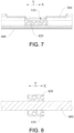
FIG. 7 is a schematic three-dimensional exploded view illustrating part of the structure of the battery apparatus according to another exemplary embodiment. -
FIG. 8 is a local cross-sectional view illustrating part of the structure of the battery apparatus shown inFIG. 7 . -
FIG. 9 is a local cross-sectional view illustrating part of the structure of the battery apparatus according to another exemplary embodiment. - The technical solutions in the exemplary embodiments of the disclosure will be described clearly and explicitly in conjunction with the drawings in the exemplary embodiments of the disclosure. The description proposed herein is just the exemplary embodiments for the purpose of illustrations only, not intended to limit the scope of the disclosure, so it should be understood that and various modifications and variations could be made thereto without departing from the scope of the disclosure.
- In the description of the present disclosure, unless otherwise specifically defined and limited, the terms "first", "second" and the like are only used for illustrative purposes and are not to be construed as expressing or implying a relative importance. The term "plurality" is two or more. The term "and/or" includes any and all combinations of one or more of the associated listed items.
- In particular, a reference to "the" object or "a" and "an" object is intended to denote also one of a possible plurality of such objects. Unless otherwise defined or described, the terms "connect", "fix" should be broadly interpreted, for example, the term "connect" can be "fixedly connect", "detachably connect", "integrally connect", "electrically connect" or "signal connect". The term "connect" also can be "directly connect" or "indirectly connect via a medium". For the persons skilled in the art, the specific meanings of the abovementioned terms in the present disclosure can be understood according to the specific situation.
- Further, in the description of the present disclosure, it should be understood that spatially relative terms, such as "above", "below" "inside", "outside" and the like, are described based on orientations illustrated in the figures, but are not intended to limit the exemplary embodiments of the present disclosure.
- In the context, it should also be understood that when an element or features is provided "outside" or "inside" of another element(s), it can be directly provided "outside" or "inside" of the other element, or be indirectly provided "outside" or "inside" of the another element(s) by an intermediate element.
- With reference to
FIG. 1 , which is a schematic three-dimensional view illustrating a structure of a battery apparatus according to disclosure. In this exemplary embodiment, a vehicle-mounted battery is treated as an example of the battery apparatus provided by the disclosure. It is easy for a person having ordinary skill in the art to understand that, in order to apply the relevant design of the disclosure to other types of battery apparatuses, various modifications, additions, substitutions, deletions or other changes may be made to the following specific embodiments, and these changes still fall within the scope of the principle of the battery apparatus provided by the disclosure. - As shown in
FIG. 1 , in this embodiment, a battery apparatus provided by the disclosure includes abox body 100 and abattery pack 200, thebattery pack 200 is accommodated in thebox body 100, and thebattery pack 200 includes a plurality ofbatteries 210 arranged in a first direction X. With reference toFIG. 2 to FIG. 4 together,FIG. 2 is a schematic three-dimensional exploded view illustrating the battery apparatus which embodies the principles of the disclosure.FIG. 3 is a schematic three-dimensional view illustrating part of the structure of the battery apparatus and specifically shows the three-dimensional structure of the combination of thebattery pack 200 and aninsulating film 400.FIG. 4 is a schematic three-dimensional view illustrating the structure of thebatteries 210 ofFIG. 2 . Hereinafter, structures, connection manners, and functional relationships of the main components of the battery apparatus provided by the disclosure are described in detail with reference to the above-mentioned figures. - As shown in
FIG. 1 to FIG. 3 , in an embodiment of the disclosure, terminal components of thebatteries 100 are located on other surfaces of thebatteries 100 except the top surfaces. For instance, the terminal components of thebattery 100 shown inFIG. 9 is located on the side of thebattery 100 that is perpendicular to the first direction, that is, the "large surface" of thebattery 100. Since the terminal components are not disposed on the top surface of thebattery 100, a collecting structure (e.g., collecting circuit board) of thebattery 100 connected to the terminal components is not disposed on a top portion of thebattery 100. That is, the top portion of thebattery 100 does not have a film material for covering the collecting structure. Based on the above, theinsulating film 400 is provided on the top portion of thebattery pack 200. Through the foregoing design, in the disclosure, through the arrangement of theinsulating film 400, when thebatteries 210 swell and deform or when the battery apparatus vibrates and a box cover 300 deforms, the resulting contact between thebattery pack 200 and thebox cover 300 or other structures located above thebattery pack 200 is prevented from occurring, and the potential safety hazard of the battery apparatus is thereby reduced. Further, the insulating film is easier to form than the insulating plate, especially the larger the size, the more difficult it is to form the insulating plate. The thickness of the insulating film is thinner, so that the top portion space and weight of the battery apparatus are saved. Besides, the insulating film is made of a flexible material and thus can be easily pressed, so that less space is additionally occupied. It should be noted that the swelling direction of a battery is in the direction perpendicular to the large surface of the battery. If the top portion of the battery is provided with a terminal component, it means that the tab of the battery needs to be connected to the terminal component, and a specific gap is certain to be left between the top cover of the battery apparatus and the battery. Therefore, even if the battery swells, it may not directly contact the top cover and may not cause deformation of the top cover, so an additional insulating film is not required to be provided on the top portion of the battery to achieve insulation. - In an embodiment of the disclosure, the
insulating film 400 may be a single-layered film structure. In some embodiments, theinsulating film 400 may be a multi-layered film structure. - In an embodiment of the disclosure, the
insulating film 400 and thebattery pack 200 may be bonded by adhesive. Through the above design, compared with the insulating plate, the insulating film may deform to a certain extent. Based on the design of adhesive bonding between the insulating film and thebattery pack 200, when thebatteries 210 swell and squeeze theinsulating film 400, theinsulating film 400 using the insulating film may deform and shrink. However, the deformation ability of the insulating plate is poor, so when thebatteries 210 swell, it is easy to apply force on the insulating plate, resulting in failure of the connection between the insulating plate and thebattery pack 200. - As shown in
FIG. 2 andFIG. 3 , based on the design that theinsulating film 400 and thebattery pack 200 are adhesively bonded, in an embodiment of the disclosure, the two ends of thebattery pack 200 is the first direction X are provided with end portion structures. The end portion structures may be batteries 210 (i.e., thebatteries 210 at the end portions of thebattery pack 200 in the first direction X) or end plates 220 (at the end portions of thebatteries 210 in the first direction X). Based on the above, theinsulating film 400 may be adhesively bonded to at least two end portion structures of thebattery pack 200. Through the above design, theinsulating film 400 may span at least part of twobatteries 210 at least. Accordingly, when thebatteries 210 swell (for example, the "large surfaces" of thebatteries 210 swell, and the "large surfaces" are the side surfaces of thebatteries 210 perpendicular to the first direction X) and gaps are formed among thebatteries 210, theinsulating film 400 is pulled, and the deformation of the insulating film may absorb the aforementioned swelling force of thebatteries 210. - As shown in
FIG. 1 and FIG. 2 , in an embodiment of the disclosure, the battery apparatus provided by the disclosure further includes thebox cover 300. Thebox cover 300 is located above the insulatingfilm 400, that is, the insulatingfilm 400 is located between thebox cover 300 and thebattery pack 200. Based on the above, the insulatingfilm 400 is adhesively bonded to thebox cover 300. Through the foregoing design, in the disclosure, the insulatingfilm 400 and thebox cover 300 are fixed by means of gluing, so that the insulatingfilm 400 and thebox cover 300 may be fixed together when the material is supplied, and the insulatingfilm 400 may be covered on thebattery pack 200 when thebox cover 300 is assembled. Accordingly, the assembly of the battery apparatus may be made more convenient, and the process step of fixing the insulatingfilm 400 to thebattery pack 200 is omitted. - As shown in
FIG. 2 andFIG. 3 , in an embodiment of the disclosure, the insulatingfilm 400 may cover all thebatteries 210 of thebattery pack 200. Through the foregoing design, in the disclosure, when thebatteries 210 swell, for example, when the "large surfaces" of thebatteries 210 swell, resulting in the formation of gaps betweenadjacent batteries 210 and the insulatingfilm 400 is pulled, the swelling force of thebatteries 210 may be absorbed through the deformation of the insulatingfilm 400. In some embodiments, the insulatingfilm 400 may cover at least part of twoadjacent batteries 210 of thebattery pack 200 at least. Accordingly, the swelling force of the twoadjacent batteries 210 may be absorbed at least through the deformation of the insulatingfilm 400, which is not limited to this embodiment. - With reference to
FIG. 5 and FIG. 6, FIG. 5 is a schematic three-dimensional exploded view illustrating part of the structure of the battery apparatus which embodies the principles of the disclosure according to another exemplary embodiment. Herein, the three-dimensional structures of the insulatingfilm 400 and thebattery pack 200 in a disassembled state are specifically shown.FIG. 6 is a local cross-sectional view schematically illustrating part of the structure of the battery apparatus shown inFIG. 5 . - As shown in
FIG. 5 and FIG. 6 , in an embodiment of the disclosure, afirst buffer layer 410 may be disposed between the insulatingfilm 400 and thebattery pack 200. That is, the insulatingfilm 400 is supported and fixed on the top surface of the battery pack through thefirst buffer layer 410, and the insulatingfilm 400 is not directly connected to thebattery pack 200. That is, a gap is provided between a portion of the insulatingfilm 400 where thefirst buffer layer 410 is not provided and thebattery pack 200. Through the foregoing design, in the disclosure, the swelling gaps of thebatteries 210 may be reserved, and support may be provided by the first buffer layer. In this way, the problems of noise generated during vibration and insulation failure caused by the contact of thebattery pack 200 with the structure above it (e.g., thebox cover 300 and the like) during collision are prevented from occurring. Further, when the top portions of thebatteries 210 haveflange structures 211 such as flange edges, if the insulatingfilm 400 directly covers the top portion of thebatteries 210, the insulatingfilm 400 using the insulating film may be pierced by theflange structures 211. Therefore, thefirst buffer layer 410 may also protect the insulatingfilm 400 from being pierced by theflange structures 211. - As shown in
FIG. 5 , based on the design that thefirst buffer layer 410 is disposed between the insulatingfilm 400 and thebattery pack 200, in an embodiment of the disclosure, thefirst buffer layer 410 may be a strip-shaped structure extending in a second direction Y, and the second direction Y is perpendicular to the first direction. - As shown in
FIG. 5 , based on the design that thefirst buffer layer 410 is disposed between the insulatingfilm 400 and thebattery pack 200, in an embodiment of the disclosure, the top portions of thebatteries 210 have theflange structures 211 protruding towards the insulatingfilm 400, such as but not limited to flange edges. Based on the above, thefirst buffer layer 410 may be disposed between theflange structures 211 of at least twoadjacent batteries 210. Through the foregoing design, in the disclosure, the limiting function of thefirst buffer layer 410 may be achieved by theflange structures 211 of twoadjacent batteries 210. - Based on the design that the
first buffer layer 410 is disposed between the insulatingfilm 400 and thebattery pack 200, in an embodiment of the disclosure, thefirst buffer layer 410 and the insulatingfilm 400 may be adhesively bonded. Through the above design, sine thefirst buffer layer 410 may deform to a certain extent, based on the design of the adhesive bonding between thefirst buffer layer 410 and thebattery pack 200, when thebatteries 210 swell and squeeze thefirst buffer layer 410, thefirst buffer layer 410 may deform and shrink. The failure of the connection between thefirst buffer layer 410 and the insulatingfilm 400 caused by force application on thefirst buffer layer 410 when thebatteries 210 swell is prevented from occurring. - Based on the design that the
first buffer layer 410 is disposed between the insulatingfilm 400 and thebattery pack 200, in an embodiment of the disclosure, the material of thefirst buffer layer 410 is buffer foam. - As shown in
FIG. 5 , based on the design that thefirst buffer layer 410 is disposed between the insulatingfilm 400 and thebattery pack 200, in an embodiment of the disclosure, a plurality of first buffer layers 410 may be disposed between the insulatingfilm 400 and thebattery pack 200, and the first buffer layers 410 are arranged at intervals in the first direction X. Through the foregoing design, in the disclosure, the swelling gaps of thebatteries 210 may be reserved, and multiple positions of the insulatingfilm 400 may be further supported and protected. - Based on the design that the first buffer layers 410 are disposed between the insulating
film 400 and thebattery pack 200, in an embodiment of the disclosure, the battery apparatus further includes thebox cover 300, and thebox cover 300 is located above the insulatingfilm 400. Based on the above, thebox cover 300 may have a plurality ofribs 310 protruding towards the insulatingfilm 400, and theribs 310 may correspond to the first buffer layers 410 one-to-one. Through the foregoing design, in the disclosure, the structural strength of thebox cover 300 may be further increased by theribs 310. Further, theribs 310 are used to correspond to thefirst buffer layer 410, so that thefirst buffer layer 410 indirectly supports theribs 310 through the insulatingfilm 400, so that thebox cover 300 is supported, and thebox cover 300 is bonded to thebattery pack 200. Thebox cover 300 is prevented from hitting thebattery pack 200 during vibration, and noise is also prevented from being generated. - With reference to
FIG. 9, FIG. 9 is a local cross-sectional view illustrating part of the structure of the battery apparatus which embodies the principles of the disclosure according to another exemplary embodiment. - As shown in
FIG. 9 , based on the arrangement that the first buffer layers 410 are disposed between the insulatingfilm 400 and thebattery pack 200 again, in an embodiment of the disclosure, a plurality of second buffer layers 420 may be disposed between the insulatingfilm 400 and thebox cover 300, and the second buffer layers 420 are arranged at intervals in the first direction X. Based on the above, the second buffer layers 420 may correspond to the first buffer layers 410 one-to-one. Through the above structural design, in the disclosure, support between the insulatingfilm 400 and thebattery pack 200 may be provided by thefirst buffer layer 410, and support between the insulatingfilm 400 and thebox cover 300 may be provided by thesecond buffer layer 420. Further, thefirst buffer layer 410 and thesecond buffer layer 420 are designed to have corresponding positions, so that thefirst buffer layer 410 and thesecond buffer layer 420 support the insulatingfilm 400 on the same position of the insulatingfilm 400. In this way, the support effect is further improved, and the deformation caused by the stress on one side (top portion or bottom portion) of supporting the insulatingfilm 400 is prevented from occurring. - With reference to
FIG. 7 and FIG. 8, FIG. 7 is a schematic three-dimensional exploded view illustrating part of the structure of the battery apparatus which embodies the principles of the disclosure according to another exemplary embodiment. Herein, the three-dimensional structures of the insulatingfilm 400 and thebattery pack 200 in a disassembled state are specifically shown.FIG. 8 is a local cross-sectional view schematically illustrating part of the structure of the battery apparatus shown inFIG. 7 . - As shown in
FIG. 7 and FIG. 8 , in an embodiment of the disclosure, the battery apparatus provided by the disclosure further includes thebox cover 300. Thebox cover 300 is located above the insulatingfilm 400, that is, the insulatingfilm 400 is located between thebox cover 300 and thebattery pack 200. Based on the above, thesecond buffer layer 420 may be disposed between the insulatingfilm 400 and thebox cover 300. Through the above design, in the disclosure, support between the insulatingfilm 400 and thebox cover 300 may be achieved by thesecond buffer layer 420. Further, the assembly process of first fixing the insulatingfilm 400 to thebattery pack 200 through thesecond buffer layer 420 and then assembling thesecond buffer layer 420 may be realized, and the assembly efficiency is high. - As shown in
FIG. 7 , based on the design that thesecond buffer layer 420 is disposed between the insulatingfilm 400 and thebox cover 300, in an embodiment of the disclosure, thesecond buffer layer 420 may be a strip-shaped structure extending in the second direction Y, and the second direction Y is perpendicular to the first direction. - As shown in
FIG. 7 , based on the design that thesecond buffer layer 420 is disposed between the insulatingfilm 400 and thebox cover 300, in an embodiment of the disclosure, the top portions of thebatteries 210 have theflange structures 211 protruding towards the insulatingfilm 400, such as but not limited to flange edges. Based on the above, the area between theflange structures 211 of at least twoadjacent batteries 210 may correspond to the position of thesecond buffer layer 420. In other words, for an orthographic projection on the bottom plate (not shown in the drawings) of thebox body 100, thesecond buffer layer 420 is located between theflange structures 211 of twoadjacent batteries 210, or when a plurality of the second buffer layers 420 are provided, at least onesecond buffer layer 420 is located between theflange structures 211 of twoadjacent batteries 210. - Based on the design that the
second buffer layer 420 is disposed between the insulatingfilm 400 and thebox cover 300, in an embodiment of the disclosure, thesecond buffer layer 420 and the insulatingfilm 400 may be adhesively bonded. Through the above design, sine thesecond buffer layer 420 may deform to a certain extent, based on the design of the adhesive bonding between thesecond buffer layer 420 and thebox cover 300, when thebatteries 210 swell and squeeze thesecond buffer layer 420, thesecond buffer layer 420 may deform and shrink. The failure of the connection between thesecond buffer layer 420 and the insulatingfilm 400 caused by force application on thesecond buffer layer 420 when thebatteries 210 swell is prevented from occurring. - Based on the design that the
second buffer layer 420 is disposed between the insulatingfilm 400 and thebox cover 300, in an embodiment of the disclosure, the material of thesecond buffer layer 420 is buffer foam. - As shown in
FIG. 7 , based on the design that thesecond buffer layer 420 is disposed between the insulatingfilm 400 and thebox cover 300, in an embodiment of the disclosure, a plurality of second buffer layers 420 may be disposed between the insulatingfilm 400 and thebox cover 300, and the second buffer layers 420 are arranged at intervals in the first direction X. Through the foregoing design, in the disclosure, support at multiple positions between the insulatingfilm 400 and thebox cover 300 may be further achieved. - Based on the design that the second buffer layers 420 are disposed between the insulating
film 400 and thebox cover 300, in an embodiment of the disclosure, thebox cover 300 may have the plurality ofribs 310 protruding towards the insulatingfilm 400, theribs 310 may correspond to the second buffer layers 420 one-to-one, and theribs 310 abut against the second buffer layers 420. Through the foregoing design, in the disclosure, the structural strength of thebox cover 300 may be further increased by theribs 310. Further, theribs 310 abut against the second buffer layers 420, so that the second buffer layers 410 support theribs 310, and thebox cover 300 is thereby supported. - As shown in
FIG. 9 , based on the arrangement that the second buffer layers 420 are disposed between the insulatingfilm 400 and thebox cover 300 again, in an embodiment of the disclosure, a plurality of the first buffer layers 410 may be disposed between the insulatingfilm 400 and thebattery pack 200, and the first buffer layers 410 are arranged at intervals in the first direction X. Based on the above, the first buffer layers 410 may correspond to the second buffer layers 420 one-to-one. Through the above structural design, in the disclosure, support between the insulatingfilm 400 and thebox cover 300 may be provided by the second buffer layers 420, and support between the insulatingfilm 400 and thebattery pack 200 may be provided by the first buffer layers 410. Further, the first buffer layers 410 and the second buffer layers 420 are designed to have corresponding positions, so that the first buffer layers 410 and the second buffer layers 420 support the insulatingfilm 400 on the same position of the insulatingfilm 400. In this way, the support effect is further improved, and the deformation caused by the stress on one side (top portion or bottom portion) of supporting the insulatingfilm 400 is prevented from occurring. - As shown in
FIG. 2 andFIG. 3 , in an embodiment of the disclosure, the insulatingfilm 400 may be an integrated structure. Through the above design, in the disclosure, the structure is simplified, the number of components is reduced, and the assembly efficiency is improved. - In an embodiment of the disclosure, an insulating
support 500 may be disposed on surfaces of thebatteries 210, for example, thebatteries 210 inFIG. 2 andFIG. 3 are actually marked at the location of the insulatingsupport 500. Herein, portions of the insulatingsupport 500 at the top portions of thebatteries 210 may be provided with openings. Through the foregoing design, in the disclosure, through the openings of the insulatingsupport 500 on the top portions, the mistake-proofing function may be provided during the assembly process. - As shown in
FIG. 4 , in an embodiment of the disclosure, in the second direction Y, a length L of each of thebatteries 210 may be 400mm to 2,500mm. Based on the above, a thickness D of thebattery 210 in the first direction X accounts for 1150 to 1/2 of the length L of thebattery 210, and the ratio of a height H of thebattery 210 in a height direction to the thickness D of thebattery 210 in the first direction X is 0.05 to 2. - Further, in an embodiment of the disclosure, the thickness D of the
battery 210 may specifically be 50mm to 200mm, such as 50mm, 100mm, 150mm, 200mm, etc. - Further, in an embodiment of the disclosure, the height H of the
battery 210 may specifically be 10mm to 100mm, such as 10mm, 30mm, 50mm, 100mm, etc. - Further, in an embodiment of the disclosure, the ratio of the thickness D of the
battery 210 to the length L of thebattery 210 may further be 1/25 to 1/4, such as 1/25, 1/10, 1/5, 1/4, etc. - Further, in an embodiment of the disclosure, the ratio of the height H of the
battery 210 to the thickness D of thebattery 210 may further be 0.1 to 0.5, such as 0.1, 0.2, 0.3, 0.5, etc. - Regarding the
battery 210 provided in the foregoing embodiment, in the case where sufficient energy density is ensured, the ratio of the length L to the thickness D of thebattery 210 is larger, and further, the ratio of the thickness D to the height H of thebattery 210 is larger. - In an embodiment of the disclosure, the ratio of the thickness D of the
battery 210 to the length L of thebattery 210 may further be 1/7 to 1/4, such as 1/7, 1/6, 1/5, 1/4, etc. That is, the ratio of the length L to the thickness D of thebattery 210 is relatively large, and in this way, the energy density of thebattery 210 is increased, and subsequent formation of thebattery pack 200 may also be conveniently performed. - In an embodiment of the disclosure, the ratio of the height H of the
battery 210 to the thickness D of thebattery 210 may be 1/7 to 1/3. That is, the ratio of the thickness D to the height H of thebattery 210 is larger, and in this way, under the condition that sufficient energy density is ensured, formation of thebattery pack 200 may be conveniently performed. - Further, in an embodiment of the disclosure, the length L of the
battery 210 may further be 500mm to 1,500mm, the thickness D of thebattery 210 may further be 80mm to 150mm, and the height of thebattery 210 may further be 15mm to 25mm. - It should be noted that each medium size of the
battery 210 shown inFIG. 4 is marked with the overall size of thebattery 210 with the insulatingsupport 500 disposed on the surface thereof. That is, the identifications of the dimensions in the related drawings include the dimensions of the insulatingsupport 500. It should be understood that in the description of the abovementioned various embodiments of the specification, it can be understood that the values of each dimension or the relationship between different dimensions includes the dimension of the insulatingsupport 500. It can also be understood that the value of each dimension or the relationship between different dimensions ignores the dimension of the insulatingsupport 500. That is, the smaller size of the insulatingsupport 500 relative to the size of thebattery 210 is regarded as not affecting the relevant values or relationships. - In view of the foregoing, the
battery pack 200 of the battery apparatus of the disclosure is provided with the insulatingfilm 400. Through the foregoing design, in the disclosure, through the arrangement of the insulatingfilm 400, when thebatteries 210 swell and deform or when the battery apparatus vibrates and thebox cover 300 deforms, the resulting contact between thebattery pack 200 and thebox cover 300 or other structures located above thebattery pack 200 is prevented from occurring, and the potential safety hazard of the battery apparatus is thereby reduced. Further, the insulating film is easier to form than the insulating plate, especially the larger the size, the more difficult it is to form the insulating plate. The thickness of the insulating film is thinner, so that the top portion space and weight of the battery apparatus are saved. Besides, the insulating film is made of a flexible material and thus can be easily pressed, so that less space is additionally occupied. - Note that the battery apparatus shown in the drawings and described in the specification are only a few examples of many types of battery apparatus that may adopt the principles of the disclosure. It should be clearly understood that the principles of the disclosure are by no means limited to any details or any components of the battery apparatus shown in the drawings or described in the specification.
- Other embodiments of the disclosure will be apparent to those skilled in the art from consideration of the specification and practice of the disclosure disclosed herein. The disclosure is intended to cover any variations, uses or adaptations of the disclosure. These variations, uses, or adaptations follow the general principles of the disclosure and include common general knowledge or conventional technical means in the art that are not disclosed in the present disclosure.
Claims (16)
- A battery apparatus comprising a battery pack (200), wherein the battery pack (200) comprises a plurality of batteries (210) arranged in a first direction (X), terminal components of the batteries (210) are located on other surfaces of the batteries (210) except top surfaces, and an insulating film (400) is provided on a top portion of the battery pack (200).
- The battery apparatus according to claim 1, wherein the insulating film (400) is adhesively bonded to the battery pack (200).
- The battery apparatus according to claim 2, wherein both ends of the battery pack (200) in the first direction (X) have end portion structures, and the end portion structures are batteries (210) or end plates (220), wherein the insulating film (400) is adhesively bonded to the two end portion structures of the battery pack (200).
- The battery apparatus according to claim 1, further comprising a box cover (300), wherein the box cover (300) is located above the insulating film (400), and the insulating film (400) is adhesively bonded to the box cover (300).
- The battery apparatus according to claim 1, wherein the insulating film (400) covers at least portions of at least two adjacent batteries (210).
- The battery apparatus according to claim 1, wherein a first buffer layer (410) is provided between the insulating film (400) and the battery pack (200).
- The battery apparatus according to claim 6, wherein a plurality of the first buffer layers (410) are provided between the insulating film (400) and the battery pack (200), and the first buffer layers (410) are arranged at intervals in the first direction (X).
- The battery apparatus according to claim 7, wherein:the battery apparatus further comprises a box cover (300), and the box cover (300) is located above the insulating film (400), wherein the box cover (300) has a plurality of ribs (310) protruding towards the insulating film (400), and the ribs (310) correspond to the first buffer layers (410) one-to-one, and/ora plurality of second buffer layers (420) are provided between the insulating film (400) and box cover (300), the second buffer layers (420) are arranged at intervals in the first direction (X), and the second buffer layers (420) correspond to the first buffer layers (410) one-to-one.
- The battery apparatus according to claim 6, wherein:top portions of the batteries (210) have flange structures (211) protruding towards the insulating film (400), and the first buffer layer (410) is provided between the flange structures (211) of at least two adjacent batteries (210),the first buffer layer (410) is adhesively bonded to the insulating film (400), and/orthe material of the first buffer layer (410) is buffer foam.
- The battery apparatus according to claim 1, further comprising a box cover (300), wherein the box cover (300) is located above the insulating film (400), and a second buffer layer (420) is provided between the insulating film (400) and the box cover (300).
- The battery apparatus according to claim 10, wherein a plurality of the second buffer layers (420) are provided between the insulating film (400) and the box cover (300), and the second buffer layers (420) are arranged at intervals in the first direction (X).
- The battery apparatus according to claim 11, wherein:the box cover (300) has a plurality of ribs (310) protruding towards the insulating film (400), the ribs (310) correspond to the second buffer layers (420) one-to-one, and the ribs (310) abut against the second buffer layers (420), and/ora plurality of first buffer layers (410) are provided between the insulating film (400) and the battery pack (200), the first buffer layers (410) are arranged at intervals in the first direction (X), and the first buffer layers (410) correspond to the second buffer layers (420) one-to-one.
- The battery apparatus according to claim 10, wherein:top portions of the batteries (210) have flange structures (211) protruding towards the insulating film (400), and an area between the flange structures (211) of at least two adjacent batteries (210) corresponds to a position of the second buffer layer (420),the second buffer layer (420) is adhesively bonded to the insulating film (400), and/orthe material of the second buffer layer (420) is buffer foam.
- The battery apparatus according to any one of claims 1-13, wherein the insulating film (400) has an integrated structure.
- The battery apparatus according to any one of claims 1-13, wherein an insulating support (500) is provided on surfaces of the batteries (210), and portions of the insulating support (500) located at top portions of the batteries (210) are provided with openings.
- The battery apparatus according to any one of claims 1-13, wherein in a second direction (Y) perpendicular to the first direction (X), a length (L) of each of the batteries (210) is 400 mm to 2,500 mm: wherein a thickness (D) of the battery in the first direction (X) accounts for 1/50 to 1/2 of the length (L) of the battery, and the ratio of a height of the battery in a height direction to the thickness (D) of the battery in the first direction (X) is 0.05 to 2.
Applications Claiming Priority (1)
| Application Number | Priority Date | Filing Date | Title |
|---|---|---|---|
| CN202210886177.0A CN115133197B (en) | 2022-07-26 | Battery device |
Publications (2)
| Publication Number | Publication Date |
|---|---|
| EP4325640A2 true EP4325640A2 (en) | 2024-02-21 |
| EP4325640A3 EP4325640A3 (en) | 2024-08-07 |
Family
ID=83385435
Family Applications (1)
| Application Number | Title | Priority Date | Filing Date |
|---|---|---|---|
| EP23155948.5A Withdrawn EP4325640A3 (en) | 2022-07-26 | 2023-02-10 | Battery apparatus |
Country Status (2)
| Country | Link |
|---|---|
| US (1) | US20240039100A1 (en) |
| EP (1) | EP4325640A3 (en) |
Cited By (1)
| Publication number | Priority date | Publication date | Assignee | Title |
|---|---|---|---|---|
| WO2025247593A1 (en) * | 2024-05-28 | 2025-12-04 | Bayerische Motoren Werke Aktiengesellschaft | Method for producing a battery or a battery module, battery or battery module, and motor vehicle comprising the battery or the battery module |
Family Cites Families (3)
| Publication number | Priority date | Publication date | Assignee | Title |
|---|---|---|---|---|
| KR102879668B1 (en) * | 2020-07-29 | 2025-10-30 | 주식회사 엘지에너지솔루션 | Battery pack and method of manufacturing the same |
| CN214043891U (en) * | 2020-12-01 | 2021-08-24 | 湖北亿纬动力有限公司 | A soft pack battery module |
| CN216850164U (en) * | 2022-03-16 | 2022-06-28 | 中创新航科技股份有限公司 | Battery device |
-
2023
- 2023-02-10 EP EP23155948.5A patent/EP4325640A3/en not_active Withdrawn
- 2023-03-09 US US18/181,506 patent/US20240039100A1/en active Pending
Cited By (1)
| Publication number | Priority date | Publication date | Assignee | Title |
|---|---|---|---|---|
| WO2025247593A1 (en) * | 2024-05-28 | 2025-12-04 | Bayerische Motoren Werke Aktiengesellschaft | Method for producing a battery or a battery module, battery or battery module, and motor vehicle comprising the battery or the battery module |
Also Published As
| Publication number | Publication date |
|---|---|
| CN115133197A (en) | 2022-09-30 |
| US20240039100A1 (en) | 2024-02-01 |
| EP4325640A3 (en) | 2024-08-07 |
Similar Documents
| Publication | Publication Date | Title |
|---|---|---|
| CN114006122B (en) | Battery pack | |
| JP5547805B2 (en) | Battery spacer, protection assembly for electrical core, and power battery | |
| KR101252413B1 (en) | Battery module and manufacturing method of battery module | |
| CN209071424U (en) | For accommodating the cabinet and battery case of battery modules | |
| JPWO2018012224A1 (en) | Battery module | |
| KR20220087529A (en) | Battery packs and electric vehicles | |
| US9196894B2 (en) | Rechargeable battery pack | |
| CN110739422B (en) | Battery cell support group and energy storage device package including the battery cell support group | |
| JP2011086623A (en) | Secondary battery | |
| EP4325640A2 (en) | Battery apparatus | |
| CN104755325A (en) | Wire harness assembly structure | |
| CN106910851B (en) | Battery module, battery package and vehicle | |
| KR20180132338A (en) | Battery pack and vehicle including the same | |
| WO2022007482A1 (en) | Vehicle and battery pack thereof | |
| JP6939631B2 (en) | Fuel cell and vehicle equipped with it | |
| CN115133197B (en) | Battery device | |
| CN121709824A (en) | A storage battery box and battery cluster | |
| KR20260028056A (en) | Thermal barrier components for battery assemblies and battery assemblies | |
| JP7047706B2 (en) | Fuel cell stack case and external restraint | |
| US12224448B2 (en) | Cell frame set and energy storage device package including cell frame set | |
| CN217823046U (en) | Battery device | |
| CN218648087U (en) | Battery pack | |
| CN220984707U (en) | Battery device | |
| CN223858245U (en) | Batteries and battery cases with encapsulated structures | |
| CN223451054U (en) | A module fixing frame |
Legal Events
| Date | Code | Title | Description |
|---|---|---|---|
| PUAI | Public reference made under article 153(3) epc to a published international application that has entered the european phase |
Free format text: ORIGINAL CODE: 0009012 |
|
| STAA | Information on the status of an ep patent application or granted ep patent |
Free format text: STATUS: REQUEST FOR EXAMINATION WAS MADE |
|
| 17P | Request for examination filed |
Effective date: 20230210 |
|
| AK | Designated contracting states |
Kind code of ref document: A2 Designated state(s): AL AT BE BG CH CY CZ DE DK EE ES FI FR GB GR HR HU IE IS IT LI LT LU LV MC ME MK MT NL NO PL PT RO RS SE SI SK SM TR |
|
| PUAL | Search report despatched |
Free format text: ORIGINAL CODE: 0009013 |
|
| AK | Designated contracting states |
Kind code of ref document: A3 Designated state(s): AL AT BE BG CH CY CZ DE DK EE ES FI FR GB GR HR HU IE IS IT LI LT LU LV MC ME MK MT NL NO PL PT RO RS SE SI SK SM TR |
|
| RIC1 | Information provided on ipc code assigned before grant |
Ipc: H01M 50/593 20210101ALI20240702BHEP Ipc: H01M 50/588 20210101ALI20240702BHEP Ipc: H01M 50/547 20210101ALI20240702BHEP Ipc: H01M 50/249 20210101ALI20240702BHEP Ipc: H01M 50/244 20210101ALI20240702BHEP Ipc: H01M 50/242 20210101ALI20240702BHEP Ipc: H01M 50/209 20210101AFI20240702BHEP |
|
| STAA | Information on the status of an ep patent application or granted ep patent |
Free format text: STATUS: THE APPLICATION IS DEEMED TO BE WITHDRAWN |
|
| 18D | Application deemed to be withdrawn |
Effective date: 20250208 |