EP4325562A1 - Semiconductor package - Google Patents
Semiconductor package Download PDFInfo
- Publication number
- EP4325562A1 EP4325562A1 EP22783274.8A EP22783274A EP4325562A1 EP 4325562 A1 EP4325562 A1 EP 4325562A1 EP 22783274 A EP22783274 A EP 22783274A EP 4325562 A1 EP4325562 A1 EP 4325562A1
- Authority
- EP
- European Patent Office
- Prior art keywords
- base plate
- region
- signal transmission
- transmission region
- interconnection
- Prior art date
- Legal status (The legal status is an assumption and is not a legal conclusion. Google has not performed a legal analysis and makes no representation as to the accuracy of the status listed.)
- Pending
Links
Images








Classifications
-
- H—ELECTRICITY
- H10—SEMICONDUCTOR DEVICES; ELECTRIC SOLID-STATE DEVICES NOT OTHERWISE PROVIDED FOR
- H10W—GENERIC PACKAGES, INTERCONNECTIONS, CONNECTORS OR OTHER CONSTRUCTIONAL DETAILS OF DEVICES COVERED BY CLASS H10
- H10W42/00—Arrangements for protection of devices
- H10W42/20—Arrangements for protection of devices protecting against electromagnetic or particle radiation, e.g. light, X-rays, gamma-rays or electrons
-
- H—ELECTRICITY
- H10—SEMICONDUCTOR DEVICES; ELECTRIC SOLID-STATE DEVICES NOT OTHERWISE PROVIDED FOR
- H10W—GENERIC PACKAGES, INTERCONNECTIONS, CONNECTORS OR OTHER CONSTRUCTIONAL DETAILS OF DEVICES COVERED BY CLASS H10
- H10W70/00—Package substrates; Interposers; Redistribution layers [RDL]
- H10W70/60—Insulating or insulated package substrates; Interposers; Redistribution layers
- H10W70/62—Insulating or insulated package substrates; Interposers; Redistribution layers characterised by their interconnections
- H10W70/65—Shapes or dispositions of interconnections
-
- H—ELECTRICITY
- H10—SEMICONDUCTOR DEVICES; ELECTRIC SOLID-STATE DEVICES NOT OTHERWISE PROVIDED FOR
- H10W—GENERIC PACKAGES, INTERCONNECTIONS, CONNECTORS OR OTHER CONSTRUCTIONAL DETAILS OF DEVICES COVERED BY CLASS H10
- H10W70/00—Package substrates; Interposers; Redistribution layers [RDL]
- H10W70/60—Insulating or insulated package substrates; Interposers; Redistribution layers
- H10W70/67—Insulating or insulated package substrates; Interposers; Redistribution layers characterised by their insulating layers or insulating parts
- H10W70/68—Shapes or dispositions thereof
- H10W70/685—Shapes or dispositions thereof comprising multiple insulating layers
-
- H—ELECTRICITY
- H10—SEMICONDUCTOR DEVICES; ELECTRIC SOLID-STATE DEVICES NOT OTHERWISE PROVIDED FOR
- H10W—GENERIC PACKAGES, INTERCONNECTIONS, CONNECTORS OR OTHER CONSTRUCTIONAL DETAILS OF DEVICES COVERED BY CLASS H10
- H10W72/00—Interconnections or connectors in packages
- H10W72/50—Bond wires
-
- H—ELECTRICITY
- H10—SEMICONDUCTOR DEVICES; ELECTRIC SOLID-STATE DEVICES NOT OTHERWISE PROVIDED FOR
- H10W—GENERIC PACKAGES, INTERCONNECTIONS, CONNECTORS OR OTHER CONSTRUCTIONAL DETAILS OF DEVICES COVERED BY CLASS H10
- H10W72/00—Interconnections or connectors in packages
- H10W72/90—Bond pads, in general
-
- H—ELECTRICITY
- H10—SEMICONDUCTOR DEVICES; ELECTRIC SOLID-STATE DEVICES NOT OTHERWISE PROVIDED FOR
- H10W—GENERIC PACKAGES, INTERCONNECTIONS, CONNECTORS OR OTHER CONSTRUCTIONAL DETAILS OF DEVICES COVERED BY CLASS H10
- H10W72/00—Interconnections or connectors in packages
- H10W72/90—Bond pads, in general
- H10W72/921—Structures or relative sizes of bond pads
- H10W72/926—Multiple bond pads having different sizes
-
- H—ELECTRICITY
- H10—SEMICONDUCTOR DEVICES; ELECTRIC SOLID-STATE DEVICES NOT OTHERWISE PROVIDED FOR
- H10W—GENERIC PACKAGES, INTERCONNECTIONS, CONNECTORS OR OTHER CONSTRUCTIONAL DETAILS OF DEVICES COVERED BY CLASS H10
- H10W74/00—Encapsulations, e.g. protective coatings
- H10W74/10—Encapsulations, e.g. protective coatings characterised by their shape or disposition
-
- H—ELECTRICITY
- H10—SEMICONDUCTOR DEVICES; ELECTRIC SOLID-STATE DEVICES NOT OTHERWISE PROVIDED FOR
- H10W—GENERIC PACKAGES, INTERCONNECTIONS, CONNECTORS OR OTHER CONSTRUCTIONAL DETAILS OF DEVICES COVERED BY CLASS H10
- H10W74/00—Encapsulations, e.g. protective coatings
- H10W74/10—Encapsulations, e.g. protective coatings characterised by their shape or disposition
- H10W74/131—Encapsulations, e.g. protective coatings characterised by their shape or disposition the semiconductor body being only partially enclosed
- H10W74/141—Encapsulations, e.g. protective coatings characterised by their shape or disposition the semiconductor body being only partially enclosed the encapsulations being on at least the sidewalls of the semiconductor body
-
- H—ELECTRICITY
- H10—SEMICONDUCTOR DEVICES; ELECTRIC SOLID-STATE DEVICES NOT OTHERWISE PROVIDED FOR
- H10W—GENERIC PACKAGES, INTERCONNECTIONS, CONNECTORS OR OTHER CONSTRUCTIONAL DETAILS OF DEVICES COVERED BY CLASS H10
- H10W80/00—Direct bonding of chips, wafers or substrates
- H10W80/701—Direct bonding of chips, wafers or substrates characterised by the pads after the direct bonding
- H10W80/721—Direct bonding of chips, wafers or substrates characterised by the pads after the direct bonding having structure or size changed during the connecting
-
- H—ELECTRICITY
- H10—SEMICONDUCTOR DEVICES; ELECTRIC SOLID-STATE DEVICES NOT OTHERWISE PROVIDED FOR
- H10W—GENERIC PACKAGES, INTERCONNECTIONS, CONNECTORS OR OTHER CONSTRUCTIONAL DETAILS OF DEVICES COVERED BY CLASS H10
- H10W90/00—Package configurations
-
- H—ELECTRICITY
- H10—SEMICONDUCTOR DEVICES; ELECTRIC SOLID-STATE DEVICES NOT OTHERWISE PROVIDED FOR
- H10W—GENERIC PACKAGES, INTERCONNECTIONS, CONNECTORS OR OTHER CONSTRUCTIONAL DETAILS OF DEVICES COVERED BY CLASS H10
- H10W90/00—Package configurations
- H10W90/401—Package configurations characterised by multiple insulating or insulated package substrates, interposers or RDLs
-
- H—ELECTRICITY
- H10—SEMICONDUCTOR DEVICES; ELECTRIC SOLID-STATE DEVICES NOT OTHERWISE PROVIDED FOR
- H10W—GENERIC PACKAGES, INTERCONNECTIONS, CONNECTORS OR OTHER CONSTRUCTIONAL DETAILS OF DEVICES COVERED BY CLASS H10
- H10W90/00—Package configurations
- H10W90/701—Package configurations characterised by the relative positions of pads or connectors relative to package parts
-
- H—ELECTRICITY
- H10—SEMICONDUCTOR DEVICES; ELECTRIC SOLID-STATE DEVICES NOT OTHERWISE PROVIDED FOR
- H10W—GENERIC PACKAGES, INTERCONNECTIONS, CONNECTORS OR OTHER CONSTRUCTIONAL DETAILS OF DEVICES COVERED BY CLASS H10
- H10W90/00—Package configurations
- H10W90/701—Package configurations characterised by the relative positions of pads or connectors relative to package parts
- H10W90/751—Package configurations characterised by the relative positions of pads or connectors relative to package parts of bond wires
- H10W90/752—Package configurations characterised by the relative positions of pads or connectors relative to package parts of bond wires between stacked chips
-
- H—ELECTRICITY
- H10—SEMICONDUCTOR DEVICES; ELECTRIC SOLID-STATE DEVICES NOT OTHERWISE PROVIDED FOR
- H10W—GENERIC PACKAGES, INTERCONNECTIONS, CONNECTORS OR OTHER CONSTRUCTIONAL DETAILS OF DEVICES COVERED BY CLASS H10
- H10W42/00—Arrangements for protection of devices
- H10W42/121—Arrangements for protection of devices protecting against mechanical damage
-
- H—ELECTRICITY
- H10—SEMICONDUCTOR DEVICES; ELECTRIC SOLID-STATE DEVICES NOT OTHERWISE PROVIDED FOR
- H10W—GENERIC PACKAGES, INTERCONNECTIONS, CONNECTORS OR OTHER CONSTRUCTIONAL DETAILS OF DEVICES COVERED BY CLASS H10
- H10W42/00—Arrangements for protection of devices
- H10W42/20—Arrangements for protection of devices protecting against electromagnetic or particle radiation, e.g. light, X-rays, gamma-rays or electrons
- H10W42/261—Arrangements for protection of devices protecting against electromagnetic or particle radiation, e.g. light, X-rays, gamma-rays or electrons characterised by their shapes or dispositions
- H10W42/271—Arrangements for protection of devices protecting against electromagnetic or particle radiation, e.g. light, X-rays, gamma-rays or electrons characterised by their shapes or dispositions the arrangements being between stacked chips
-
- H—ELECTRICITY
- H10—SEMICONDUCTOR DEVICES; ELECTRIC SOLID-STATE DEVICES NOT OTHERWISE PROVIDED FOR
- H10W—GENERIC PACKAGES, INTERCONNECTIONS, CONNECTORS OR OTHER CONSTRUCTIONAL DETAILS OF DEVICES COVERED BY CLASS H10
- H10W70/00—Package substrates; Interposers; Redistribution layers [RDL]
- H10W70/60—Insulating or insulated package substrates; Interposers; Redistribution layers
-
- H—ELECTRICITY
- H10—SEMICONDUCTOR DEVICES; ELECTRIC SOLID-STATE DEVICES NOT OTHERWISE PROVIDED FOR
- H10W—GENERIC PACKAGES, INTERCONNECTIONS, CONNECTORS OR OTHER CONSTRUCTIONAL DETAILS OF DEVICES COVERED BY CLASS H10
- H10W70/00—Package substrates; Interposers; Redistribution layers [RDL]
- H10W70/60—Insulating or insulated package substrates; Interposers; Redistribution layers
- H10W70/611—Insulating or insulated package substrates; Interposers; Redistribution layers for connecting multiple chips together
-
- H—ELECTRICITY
- H10—SEMICONDUCTOR DEVICES; ELECTRIC SOLID-STATE DEVICES NOT OTHERWISE PROVIDED FOR
- H10W—GENERIC PACKAGES, INTERCONNECTIONS, CONNECTORS OR OTHER CONSTRUCTIONAL DETAILS OF DEVICES COVERED BY CLASS H10
- H10W72/00—Interconnections or connectors in packages
- H10W72/01—Manufacture or treatment
-
- H—ELECTRICITY
- H10—SEMICONDUCTOR DEVICES; ELECTRIC SOLID-STATE DEVICES NOT OTHERWISE PROVIDED FOR
- H10W—GENERIC PACKAGES, INTERCONNECTIONS, CONNECTORS OR OTHER CONSTRUCTIONAL DETAILS OF DEVICES COVERED BY CLASS H10
- H10W72/00—Interconnections or connectors in packages
- H10W72/071—Connecting or disconnecting
- H10W72/072—Connecting or disconnecting of bump connectors
- H10W72/07251—Connecting or disconnecting of bump connectors characterised by changes in properties of the bump connectors during connecting
- H10W72/07254—Connecting or disconnecting of bump connectors characterised by changes in properties of the bump connectors during connecting changes in dispositions
-
- H—ELECTRICITY
- H10—SEMICONDUCTOR DEVICES; ELECTRIC SOLID-STATE DEVICES NOT OTHERWISE PROVIDED FOR
- H10W—GENERIC PACKAGES, INTERCONNECTIONS, CONNECTORS OR OTHER CONSTRUCTIONAL DETAILS OF DEVICES COVERED BY CLASS H10
- H10W72/00—Interconnections or connectors in packages
- H10W72/071—Connecting or disconnecting
- H10W72/073—Connecting or disconnecting of die-attach connectors
-
- H—ELECTRICITY
- H10—SEMICONDUCTOR DEVICES; ELECTRIC SOLID-STATE DEVICES NOT OTHERWISE PROVIDED FOR
- H10W—GENERIC PACKAGES, INTERCONNECTIONS, CONNECTORS OR OTHER CONSTRUCTIONAL DETAILS OF DEVICES COVERED BY CLASS H10
- H10W72/00—Interconnections or connectors in packages
- H10W72/071—Connecting or disconnecting
- H10W72/073—Connecting or disconnecting of die-attach connectors
- H10W72/07351—Connecting or disconnecting of die-attach connectors characterised by changes in properties of the die-attach connectors during connecting
- H10W72/07354—Connecting or disconnecting of die-attach connectors characterised by changes in properties of the die-attach connectors during connecting changes in dispositions
-
- H—ELECTRICITY
- H10—SEMICONDUCTOR DEVICES; ELECTRIC SOLID-STATE DEVICES NOT OTHERWISE PROVIDED FOR
- H10W—GENERIC PACKAGES, INTERCONNECTIONS, CONNECTORS OR OTHER CONSTRUCTIONAL DETAILS OF DEVICES COVERED BY CLASS H10
- H10W72/00—Interconnections or connectors in packages
- H10W72/071—Connecting or disconnecting
- H10W72/075—Connecting or disconnecting of bond wires
-
- H—ELECTRICITY
- H10—SEMICONDUCTOR DEVICES; ELECTRIC SOLID-STATE DEVICES NOT OTHERWISE PROVIDED FOR
- H10W—GENERIC PACKAGES, INTERCONNECTIONS, CONNECTORS OR OTHER CONSTRUCTIONAL DETAILS OF DEVICES COVERED BY CLASS H10
- H10W72/00—Interconnections or connectors in packages
- H10W72/20—Bump connectors, e.g. solder bumps or copper pillars; Dummy bumps; Thermal bumps
- H10W72/241—Dispositions, e.g. layouts
- H10W72/242—Dispositions, e.g. layouts relative to the surface, e.g. recessed, protruding
-
- H—ELECTRICITY
- H10—SEMICONDUCTOR DEVICES; ELECTRIC SOLID-STATE DEVICES NOT OTHERWISE PROVIDED FOR
- H10W—GENERIC PACKAGES, INTERCONNECTIONS, CONNECTORS OR OTHER CONSTRUCTIONAL DETAILS OF DEVICES COVERED BY CLASS H10
- H10W72/00—Interconnections or connectors in packages
- H10W72/20—Bump connectors, e.g. solder bumps or copper pillars; Dummy bumps; Thermal bumps
- H10W72/241—Dispositions, e.g. layouts
- H10W72/244—Dispositions, e.g. layouts relative to underlying supporting features, e.g. bond pads, RDLs or vias
-
- H—ELECTRICITY
- H10—SEMICONDUCTOR DEVICES; ELECTRIC SOLID-STATE DEVICES NOT OTHERWISE PROVIDED FOR
- H10W—GENERIC PACKAGES, INTERCONNECTIONS, CONNECTORS OR OTHER CONSTRUCTIONAL DETAILS OF DEVICES COVERED BY CLASS H10
- H10W72/00—Interconnections or connectors in packages
- H10W72/20—Bump connectors, e.g. solder bumps or copper pillars; Dummy bumps; Thermal bumps
- H10W72/241—Dispositions, e.g. layouts
- H10W72/247—Dispositions of multiple bumps
-
- H—ELECTRICITY
- H10—SEMICONDUCTOR DEVICES; ELECTRIC SOLID-STATE DEVICES NOT OTHERWISE PROVIDED FOR
- H10W—GENERIC PACKAGES, INTERCONNECTIONS, CONNECTORS OR OTHER CONSTRUCTIONAL DETAILS OF DEVICES COVERED BY CLASS H10
- H10W72/00—Interconnections or connectors in packages
- H10W72/20—Bump connectors, e.g. solder bumps or copper pillars; Dummy bumps; Thermal bumps
- H10W72/251—Materials
- H10W72/252—Materials comprising solid metals or solid metalloids, e.g. PbSn, Ag or Cu
-
- H—ELECTRICITY
- H10—SEMICONDUCTOR DEVICES; ELECTRIC SOLID-STATE DEVICES NOT OTHERWISE PROVIDED FOR
- H10W—GENERIC PACKAGES, INTERCONNECTIONS, CONNECTORS OR OTHER CONSTRUCTIONAL DETAILS OF DEVICES COVERED BY CLASS H10
- H10W72/00—Interconnections or connectors in packages
- H10W72/20—Bump connectors, e.g. solder bumps or copper pillars; Dummy bumps; Thermal bumps
- H10W72/29—Bond pads specially adapted therefor
-
- H—ELECTRICITY
- H10—SEMICONDUCTOR DEVICES; ELECTRIC SOLID-STATE DEVICES NOT OTHERWISE PROVIDED FOR
- H10W—GENERIC PACKAGES, INTERCONNECTIONS, CONNECTORS OR OTHER CONSTRUCTIONAL DETAILS OF DEVICES COVERED BY CLASS H10
- H10W72/00—Interconnections or connectors in packages
- H10W72/30—Die-attach connectors
- H10W72/341—Dispositions of die-attach connectors, e.g. layouts
- H10W72/347—Dispositions of multiple die-attach connectors
-
- H—ELECTRICITY
- H10—SEMICONDUCTOR DEVICES; ELECTRIC SOLID-STATE DEVICES NOT OTHERWISE PROVIDED FOR
- H10W—GENERIC PACKAGES, INTERCONNECTIONS, CONNECTORS OR OTHER CONSTRUCTIONAL DETAILS OF DEVICES COVERED BY CLASS H10
- H10W72/00—Interconnections or connectors in packages
- H10W72/30—Die-attach connectors
- H10W72/351—Materials of die-attach connectors
- H10W72/353—Materials of die-attach connectors not comprising solid metals or solid metalloids, e.g. ceramics
- H10W72/354—Materials of die-attach connectors not comprising solid metals or solid metalloids, e.g. ceramics comprising polymers
-
- H—ELECTRICITY
- H10—SEMICONDUCTOR DEVICES; ELECTRIC SOLID-STATE DEVICES NOT OTHERWISE PROVIDED FOR
- H10W—GENERIC PACKAGES, INTERCONNECTIONS, CONNECTORS OR OTHER CONSTRUCTIONAL DETAILS OF DEVICES COVERED BY CLASS H10
- H10W72/00—Interconnections or connectors in packages
- H10W72/50—Bond wires
- H10W72/531—Shapes of wire connectors
- H10W72/5366—Shapes of wire connectors the bond wires having kinks
-
- H—ELECTRICITY
- H10—SEMICONDUCTOR DEVICES; ELECTRIC SOLID-STATE DEVICES NOT OTHERWISE PROVIDED FOR
- H10W—GENERIC PACKAGES, INTERCONNECTIONS, CONNECTORS OR OTHER CONSTRUCTIONAL DETAILS OF DEVICES COVERED BY CLASS H10
- H10W72/00—Interconnections or connectors in packages
- H10W72/851—Dispositions of multiple connectors or interconnections
- H10W72/853—On the same surface
- H10W72/865—Die-attach connectors and bond wires
-
- H—ELECTRICITY
- H10—SEMICONDUCTOR DEVICES; ELECTRIC SOLID-STATE DEVICES NOT OTHERWISE PROVIDED FOR
- H10W—GENERIC PACKAGES, INTERCONNECTIONS, CONNECTORS OR OTHER CONSTRUCTIONAL DETAILS OF DEVICES COVERED BY CLASS H10
- H10W72/00—Interconnections or connectors in packages
- H10W72/851—Dispositions of multiple connectors or interconnections
- H10W72/874—On different surfaces
- H10W72/877—Bump connectors and die-attach connectors
-
- H—ELECTRICITY
- H10—SEMICONDUCTOR DEVICES; ELECTRIC SOLID-STATE DEVICES NOT OTHERWISE PROVIDED FOR
- H10W—GENERIC PACKAGES, INTERCONNECTIONS, CONNECTORS OR OTHER CONSTRUCTIONAL DETAILS OF DEVICES COVERED BY CLASS H10
- H10W72/00—Interconnections or connectors in packages
- H10W72/851—Dispositions of multiple connectors or interconnections
- H10W72/874—On different surfaces
- H10W72/884—Die-attach connectors and bond wires
-
- H—ELECTRICITY
- H10—SEMICONDUCTOR DEVICES; ELECTRIC SOLID-STATE DEVICES NOT OTHERWISE PROVIDED FOR
- H10W—GENERIC PACKAGES, INTERCONNECTIONS, CONNECTORS OR OTHER CONSTRUCTIONAL DETAILS OF DEVICES COVERED BY CLASS H10
- H10W72/00—Interconnections or connectors in packages
- H10W72/90—Bond pads, in general
- H10W72/941—Dispositions of bond pads
- H10W72/9415—Dispositions of bond pads relative to the surface, e.g. recessed, protruding
-
- H—ELECTRICITY
- H10—SEMICONDUCTOR DEVICES; ELECTRIC SOLID-STATE DEVICES NOT OTHERWISE PROVIDED FOR
- H10W—GENERIC PACKAGES, INTERCONNECTIONS, CONNECTORS OR OTHER CONSTRUCTIONAL DETAILS OF DEVICES COVERED BY CLASS H10
- H10W72/00—Interconnections or connectors in packages
- H10W72/90—Bond pads, in general
- H10W72/941—Dispositions of bond pads
- H10W72/942—Dispositions of bond pads relative to underlying supporting features, e.g. bond pads, RDLs or vias
-
- H—ELECTRICITY
- H10—SEMICONDUCTOR DEVICES; ELECTRIC SOLID-STATE DEVICES NOT OTHERWISE PROVIDED FOR
- H10W—GENERIC PACKAGES, INTERCONNECTIONS, CONNECTORS OR OTHER CONSTRUCTIONAL DETAILS OF DEVICES COVERED BY CLASS H10
- H10W74/00—Encapsulations, e.g. protective coatings
-
- H—ELECTRICITY
- H10—SEMICONDUCTOR DEVICES; ELECTRIC SOLID-STATE DEVICES NOT OTHERWISE PROVIDED FOR
- H10W—GENERIC PACKAGES, INTERCONNECTIONS, CONNECTORS OR OTHER CONSTRUCTIONAL DETAILS OF DEVICES COVERED BY CLASS H10
- H10W74/00—Encapsulations, e.g. protective coatings
- H10W74/01—Manufacture or treatment
- H10W74/016—Manufacture or treatment using moulds
-
- H—ELECTRICITY
- H10—SEMICONDUCTOR DEVICES; ELECTRIC SOLID-STATE DEVICES NOT OTHERWISE PROVIDED FOR
- H10W—GENERIC PACKAGES, INTERCONNECTIONS, CONNECTORS OR OTHER CONSTRUCTIONAL DETAILS OF DEVICES COVERED BY CLASS H10
- H10W90/00—Package configurations
- H10W90/20—Configurations of stacked chips
- H10W90/24—Configurations of stacked chips at least one of the stacked chips being laterally offset from a neighbouring stacked chip, e.g. chip stacks having a staircase shape
-
- H—ELECTRICITY
- H10—SEMICONDUCTOR DEVICES; ELECTRIC SOLID-STATE DEVICES NOT OTHERWISE PROVIDED FOR
- H10W—GENERIC PACKAGES, INTERCONNECTIONS, CONNECTORS OR OTHER CONSTRUCTIONAL DETAILS OF DEVICES COVERED BY CLASS H10
- H10W90/00—Package configurations
- H10W90/20—Configurations of stacked chips
- H10W90/288—Configurations of stacked chips characterised by arrangements for thermal management of the stacked chips
-
- H—ELECTRICITY
- H10—SEMICONDUCTOR DEVICES; ELECTRIC SOLID-STATE DEVICES NOT OTHERWISE PROVIDED FOR
- H10W—GENERIC PACKAGES, INTERCONNECTIONS, CONNECTORS OR OTHER CONSTRUCTIONAL DETAILS OF DEVICES COVERED BY CLASS H10
- H10W90/00—Package configurations
- H10W90/20—Configurations of stacked chips
- H10W90/291—Configurations of stacked chips characterised by containers, encapsulations, or other housings for the stacked chips
-
- H—ELECTRICITY
- H10—SEMICONDUCTOR DEVICES; ELECTRIC SOLID-STATE DEVICES NOT OTHERWISE PROVIDED FOR
- H10W—GENERIC PACKAGES, INTERCONNECTIONS, CONNECTORS OR OTHER CONSTRUCTIONAL DETAILS OF DEVICES COVERED BY CLASS H10
- H10W90/00—Package configurations
- H10W90/20—Configurations of stacked chips
- H10W90/297—Configurations of stacked chips characterised by the through-semiconductor vias [TSVs] in the stacked chips
-
- H—ELECTRICITY
- H10—SEMICONDUCTOR DEVICES; ELECTRIC SOLID-STATE DEVICES NOT OTHERWISE PROVIDED FOR
- H10W—GENERIC PACKAGES, INTERCONNECTIONS, CONNECTORS OR OTHER CONSTRUCTIONAL DETAILS OF DEVICES COVERED BY CLASS H10
- H10W90/00—Package configurations
- H10W90/701—Package configurations characterised by the relative positions of pads or connectors relative to package parts
- H10W90/721—Package configurations characterised by the relative positions of pads or connectors relative to package parts of bump connectors
- H10W90/722—Package configurations characterised by the relative positions of pads or connectors relative to package parts of bump connectors between stacked chips
-
- H—ELECTRICITY
- H10—SEMICONDUCTOR DEVICES; ELECTRIC SOLID-STATE DEVICES NOT OTHERWISE PROVIDED FOR
- H10W—GENERIC PACKAGES, INTERCONNECTIONS, CONNECTORS OR OTHER CONSTRUCTIONAL DETAILS OF DEVICES COVERED BY CLASS H10
- H10W90/00—Package configurations
- H10W90/701—Package configurations characterised by the relative positions of pads or connectors relative to package parts
- H10W90/721—Package configurations characterised by the relative positions of pads or connectors relative to package parts of bump connectors
- H10W90/724—Package configurations characterised by the relative positions of pads or connectors relative to package parts of bump connectors between a chip and a stacked insulating package substrate, interposer or RDL
-
- H—ELECTRICITY
- H10—SEMICONDUCTOR DEVICES; ELECTRIC SOLID-STATE DEVICES NOT OTHERWISE PROVIDED FOR
- H10W—GENERIC PACKAGES, INTERCONNECTIONS, CONNECTORS OR OTHER CONSTRUCTIONAL DETAILS OF DEVICES COVERED BY CLASS H10
- H10W90/00—Package configurations
- H10W90/701—Package configurations characterised by the relative positions of pads or connectors relative to package parts
- H10W90/731—Package configurations characterised by the relative positions of pads or connectors relative to package parts of die-attach connectors
- H10W90/732—Package configurations characterised by the relative positions of pads or connectors relative to package parts of die-attach connectors between stacked chips
-
- H—ELECTRICITY
- H10—SEMICONDUCTOR DEVICES; ELECTRIC SOLID-STATE DEVICES NOT OTHERWISE PROVIDED FOR
- H10W—GENERIC PACKAGES, INTERCONNECTIONS, CONNECTORS OR OTHER CONSTRUCTIONAL DETAILS OF DEVICES COVERED BY CLASS H10
- H10W90/00—Package configurations
- H10W90/701—Package configurations characterised by the relative positions of pads or connectors relative to package parts
- H10W90/731—Package configurations characterised by the relative positions of pads or connectors relative to package parts of die-attach connectors
- H10W90/734—Package configurations characterised by the relative positions of pads or connectors relative to package parts of die-attach connectors between a chip and a stacked insulating package substrate, interposer or RDL
-
- H—ELECTRICITY
- H10—SEMICONDUCTOR DEVICES; ELECTRIC SOLID-STATE DEVICES NOT OTHERWISE PROVIDED FOR
- H10W—GENERIC PACKAGES, INTERCONNECTIONS, CONNECTORS OR OTHER CONSTRUCTIONAL DETAILS OF DEVICES COVERED BY CLASS H10
- H10W90/00—Package configurations
- H10W90/701—Package configurations characterised by the relative positions of pads or connectors relative to package parts
- H10W90/751—Package configurations characterised by the relative positions of pads or connectors relative to package parts of bond wires
- H10W90/754—Package configurations characterised by the relative positions of pads or connectors relative to package parts of bond wires between a chip and a stacked insulating package substrate, interposer or RDL
Definitions
- the disclosure relates to the technical field of semiconductors, and in particular, to a semiconductor package.
- an embodiment of the disclosure provides a semiconductor package.
- a first aspect of the embodiments of the disclosure provides a semiconductor package, including a first base plate, a first semiconductor structure, a second base plate and a filling layer.
- the first base plate has a first surface.
- the first surface includes a first signal transmission region and a second signal transmission region.
- the first semiconductor structure is located on the first surface of the first base plate and electrically connected to the first signal transmission region.
- the second base plate is located on the first base plate and includes a base and a first interconnection surface located on the base.
- the first interconnection surface of the second base plate is away from the first surface of the first base plate.
- the first interconnection surface has a first interconnection region and a second interconnection region that communicate with each other.
- the first interconnection region is electrically connected to the second signal transmission region.
- the filling layer seals the first semiconductor structure, the second base plate and the first surface of the first base plate.
- the first interconnection region is not sealed by the filling layer, and the second interconnection region is sealed by the filling layer.
- the first surface of the first base plate further includes a third signal transmission region located between the first signal transmission region and the second signal transmission region.
- the first semiconductor structure is located on the third signal transmission region.
- the first surface of the first base plate further includes a fourth signal transmission region.
- the second base plate is located on the fourth signal transmission region.
- the second signal transmission region is electrically connected to the fourth signal transmission region.
- the second base plate is located on the first semiconductor structure.
- the first interconnection region is electrically connected to the second signal transmission region by means of the second interconnection region.
- the third signal transmission region includes a first signal sub-region and a second signal sub-region.
- the first signal sub-region is connected to the first signal transmission region and located in a close region of the first signal transmission region.
- the second signal sub-region is connected to the second signal transmission region and located in a close region of the second signal transmission region.
- the fourth signal transmission region is electrically connected to the first interconnection region.
- the first signal transmission region and the second signal transmission region are located at two opposite sides of the first base plate.
- the first semiconductor structure has a first connection end.
- the first connection end and the first signal transmission region are located at the same side and connected to each other by using a lead wire.
- the second interconnection region and the second signal transmission region are located at the same side and connected to each other by using a lead wire.
- the first semiconductor structure is connected to the first signal transmission region in a direction perpendicular to the first base plate.
- the first semiconductor structure is connected to the third signal transmission region in the direction perpendicular to the first base plate.
- the first signal transmission region is connected to the third signal transmission region.
- the second base plate further includes a second interconnection surface located on the other surface of the base.
- the base has a channel that connects the first interconnection region and the second interconnection surface.
- the first interconnection region is connected to the second signal transmission region by means of the channel in a direction perpendicular to the first base plate.
- the base of the second base plate has an electromagnetic shielding layer.
- the first base plate has a second surface facing away from the first surface. There is a circuit channel between the first surface and the second surface.
- the second surface of the first base plate has a plurality of first connection pads.
- the first interconnection region of the second base plate has a plurality of second connection pads.
- An area of the second connection pad is greater than or equal to an area of the first connection pad.
- the second interconnection region of the second base plate has a plurality of third connection pads.
- An area of the third connection pad is less than the area of the second connection pad.
- the first signal transmission region of the first base plate has a plurality of fourth connection pads.
- An area of the fourth connection pad is less than or equal to the area of the first connection pad.
- the number of the third connection pads is greater than the number of the second connection pads.
- the first base plate in a direction perpendicular to the first base plate, has a first thickness. In a direction perpendicular to the second base plate, the second base plate has a second thickness. The first thickness is less than the second thickness.
- the semiconductor package further includes a second package.
- the second package has a contact surface.
- the second package is connected to the first interconnection region by means of the contact surface.
- the contact surface of the second package has a first contact structure.
- the first contact structure has, in a direction perpendicular to the contact surface, a first height protruding from the contact surface. The first height is greater than the preset height.
- the first connection pad of the first base plate has a second contact structure protruding from the first base plate.
- the second contact structure has, in a direction perpendicular to the first base plate, a second height protruding from the first base plate. The second height is less than or equal to the first height.
- the second package includes a second semiconductor structure.
- the type of the second semiconductor structure is the same as or different from the type of the first semiconductor structure.
- subsequent other semiconductor structures may be connected to the first semiconductor structure and the first base plate by means of the first interconnection region of the second base plate. Therefore, the connection among the semiconductor structures of different types or different specifications can be realized, so as to cause a combination among different semiconductor structures to be more flexible.
- first semiconductor structure and subsequent other semiconductor structures connected to the first semiconductor structure are packaged independently, test and failure analysis are easier to perform. Since there is the preset height between the first interconnection region of the second base plate and the top surface of the filling layer, other semiconductor structures may be placed on the first interconnection region, within a region enclosed by the filling layer, so that the height and size of the entire structure can be reduced.
- first element, component, region, layer or section discussed below may be represented as a second element, component, region, layer or section. While the second element, component, region, layer or section is discussed, it does not mean that the first element, component, region, layer or section is necessarily existent in the disclosure.
- Spatial relation terms such as “under”, “below”, “lower”, “underneath”, “above”, “upper” and the like, may be used here for conveniently describing so that a relationship between one element or feature shown in the drawings and other elements or features is described. It should be understood that in addition to orientations shown in the drawings, the spatial relationship terms are intended to further include the different orientations of a device in use and operation. For example, if the device in the drawings is turned over, then the elements or the features described as “below” or “underneath” or “under” other elements may be oriented “on” the other elements or features. Therefore, the exemplary terms “below” and “under” may include two orientations of up and down. The device may be otherwise oriented (rotated by 90 degrees or other orientations) and the spatial descriptions used here are interpreted accordingly.
- a current semiconductor package technology generally uses a discrete method or a UFS Multi Chip Package (UMCP) method.
- the discrete method is, for example, to distribute a DRAM chip and an NAND chip for package.
- the UMCP is, for example, to package a memory chip and a control chip in the same package structure.
- Packaging by means of the discrete method causes the package structure to occupy a large area of a PCB, and the UMCP method may cause difficult test and failure analysis and poor heat dissipation of a controller.
- chips of different capacities cannot be flexibly combined.
- FIG. 1 is a schematic structural diagram of a semiconductor package according to an embodiment of the disclosure.
- the semiconductor package includes a first base plate 10, a first semiconductor structure 20, a second base plate 30 and a filling layer 40.
- the first base plate 10 has a first surface 101.
- the first surface 101 includes a first signal transmission region 11 and a second signal transmission region 12.
- the first semiconductor structure 20 is located on the first surface 101 of the first base plate 10 and electrically connected to the first signal transmission region 11.
- the second base plate 30 is located above the first base plate 10 and includes a base 33 and a first interconnection surface 301 located on the base 33.
- the first interconnection surface 301 of the second base plate 30 is away from the first surface 101 of the first base plate 10.
- the first interconnection surface 301 has a first interconnection region 31 and a second interconnection region 32 that communicate with each other.
- the first interconnection region 31 is electrically connected to the second signal transmission region 12.
- the filling layer 40 seals the first semiconductor structure 20, the second base plate 30 and the first surface 101 of the first base plate 10.
- the first interconnection region 31 is not sealed by the filling layer 40
- the second interconnection region 32 is sealed by the filling layer 40.
- subsequent other semiconductor structures can be connected to the first semiconductor structure and the first base plate by the first interconnection region on the second base plate.
- the connection among the semiconductor structures of different types or different specifications can be realized, a combination among different semiconductor structures can be more flexible.
- first semiconductor structure and subsequent other semiconductor structures connected to the first semiconductor structure are packaged independently, test and failure analysis are easier to perform. Since there is the preset height between the first interconnection region of the second base plate and the top surface of the filling layer, other semiconductor structures may be placed on the first interconnection region, within a region enclosed by the filling layer, so that the height and size of the entire structure can be reduced.
- FIG. 2 is a schematic structural diagram of a first base plate according to an embodiment of the disclosure.
- the first base plate 10 may be a Printed Circuit Board (PCB) or a redistribution base plate.
- PCB Printed Circuit Board
- the first base plate 10 includes a first base 15, and a first upper insulating dielectric layer 16 and a first lower insulating dielectric layer 17 that are respectively located on an upper surface and lower surface of the first base 15.
- the first base 15 may be a silicon substrate, a germanium substrate, a silicon germanium substrate, a silicon carbide substrate, a Silicon On Insulator (SOI) substrate, or a Germanium On Insulator (GOI) substrate, or may be a substrate including other element semiconductors or compound semiconductors, such as a glass substrate or a III-V compound substrates (for example, a gallium nitride substrate or a gallium arsenide substrate), or may be a laminated structure such as Si/SiGe, or may be other epitaxial structures such as Silicon Germanium On Insulator (SGOI).
- SOI Silicon On Insulator
- GOI Germanium On Insulator
- the first upper insulating dielectric layer 16 and the first lower insulating dielectric layer 17 may be solder mask layers.
- materials of the first upper insulating dielectric layer 16 and the first lower insulating dielectric layer 17 may be green paint.
- the first base plate 10 has a second surface 102 facing away from the first surface 101. There are circuit channels 151 between the first surface 101 and the second surface 102. The second surface 102 of the first base plate 10 has a plurality of first connection pads 171.
- the first surface of the first base plate 10 has a plurality of sixth connection pads 161.
- the circuit channel 151 connects the sixth connection pad 161 and the first connection pad 171.
- the first signal transmission region 11 of the first base plate 10 has a plurality of fourth connection pads 111.
- An area of the fourth connection pad 111 is less than or equal to the area of the first connection pad 171.
- the area of the fourth connection pad 111 is less than the area of the first connection pad 171
- more efficient signal transmission efficiency between the first semiconductor structure 20 and the first signal transmission region 11 of the first base plate 10 can be achieved, and a chip area can be reduced.
- the area of the first connection pad 171 is greater than that of the fourth connection pad 111, the conductive efficiency and heat conduction efficiency between the first semiconductor structure 20 and the first base plate 10 can be enhanced.
- the first signal transmission region of the first base plate 10 is electrically connected to the second surface.
- the first connection pad 171 of the first base plate 10 has a second contact structure 18 protruding from the first base plate 10.
- the second contact structure 18 may electrically connect the semiconductor package to an external apparatus, so that at least one of a control signal, a power signal or a grounding signal that are used to operate the first semiconductor structure may be received from the external apparatus, or a data signal to be stored in the first semiconductor structure may be received from the external apparatus. Alternatively, data in the first semiconductor structure may also be provided to the external apparatus.
- the second contact structure 18 includes a conductive material.
- the second contact structure 18 is a solder ball. It is understandable that, a shape of the second contact structure provided in the embodiments of the disclosure is only a specific and feasible implementation in the embodiments of the disclosure, and does not constitute a limitation of the disclosure.
- the second contact structure may also be a structure with other shapes. The number, spacing, and location of the second contact structures are not limited to any specific arrangement, and various modifications may be made.
- the first surface 101 of the first base plate 10 includes a first signal transmission region 11 and a second signal transmission region 12.
- the first signal transmission region 11 is electrically connected to the first semiconductor structure 20.
- the second signal transmission region 12 is electrically connected to the second base plate 30.
- the first signal transmission region 11 and the second signal transmission region 12 are not connected to each other.
- the first surface 101 of the first base plate 10 further includes a third signal transmission region 13 located between the first signal transmission region 11 and the second signal transmission region 12.
- the first semiconductor structure 20 is located on the third signal transmission region 13.
- the first signal transmission region 11 is located outside the first semiconductor structure 20, so that the connection stability between the first signal transmission region 11 and the first semiconductor structure 20 can be increased.
- an area of a distribution region of the first signal transmission region 11 on the first base plate 10 may be less than an area of a distribution region of the third signal transmission region 13 on the first base plate 10, so that a lateral dimension of a first package can be decreased, and an integration level can be enhanced.
- the first semiconductor structure 20 includes a plurality of first semiconductor chips 21 that are successively stacked in a direction perpendicular to the first base plate 10. In this embodiment, by means of successively stacking the plurality of first semiconductor chips upwards, a horizontal area of the semiconductor package can be saved.
- the first semiconductor chip may be a DRAM chip.
- the second base plate 30 is located on the first semiconductor structure 20.
- the first interconnection region 31 is electrically connected to the second signal transmission region 12 by means of the second interconnection region 32.
- the third signal transmission region 13 includes a first signal sub-region 131 and a second signal sub-region 132.
- the first signal sub-region 131 is connected to the first signal transmission region 11 and located in a close region of the first signal transmission region 11.
- the second signal sub-region 132 is connected to the second signal transmission region 12 and located in a close region of the second signal transmission region 12.
- the first signal sub-region 131 and the second signal sub-region 132 are not connected to each other.
- an electromagnetic shielding structure (not shown) between the first signal sub-region 131 and the second signal sub-region 132 of the first base plate 10.
- the first signal sub-region 131 is connected to the first signal transmission region 11
- the second signal sub-region 132 is connected to the second signal transmission region
- the first signal transmission region is connected to the first semiconductor structure
- the second signal transmission region is indirectly connected to a second package by being connected to the second base plate, by disposing the electromagnetic shielding structure between the first signal sub-region and the second signal sub-region, signal interference between the first semiconductor structure and the second package can be prevented.
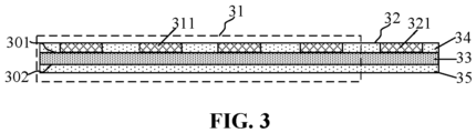
- FIG. 3 is a schematic structural diagram of a second base plate according to an embodiment of the disclosure.
- the second base plate 30 includes a base 33, and an upper insulating dielectric layer 34 and a lower insulating dielectric layer 35 that are respectively located on an upper surface and lower surface of the base 33.
- the base 33 may be a silicon substrate, a germanium substrate, a silicon germanium substrate, a silicon carbide substrate, an SOI substrate, or a GOI substrate, or may be a substrate including other element semiconductors or compound semiconductors, such as a glass substrate or a III-V compound substrates (for example, a gallium nitride substrate or a gallium arsenide substrate), or may be a laminated structure such as Si/SiGe, or may be other epitaxial structures such as SGOI.
- the upper insulating dielectric layer 34 and the lower insulating dielectric layer 35 may be solder mask layers.
- materials of the upper insulating dielectric layer 34 and the lower insulating dielectric layer 35 may be green paint.
- the first interconnection region 31 of the second base plate 30 has a plurality of second connection pads 311. An area of the second connection pad 311 is greater than or equal to an area of the first connection pad 171.
- a contact area when the second package is in contact with the second connection pad 311 can be enlarged. If the contact area is relatively small, it is very difficult to dismount after soldering, so that more convenient follow-up disassembly and reassembly can be realized by enlarging the contact area.
- the second interconnection region 32 of the second base plate 30 has a plurality of third connection pads 321.
- An area of the third connection pad 321 is less than the area of the second connection pad 311.
- the number of the third connection pads 321 is greater than the number of the second connection pads 311.
- the third connection pad carries the interconnection between the second package and the first base plate, so that the layout design is more flexible.
- the base 33 of the second base plate 30 has an electromagnetic shielding layer (not shown). By disposing the electromagnetic shielding layer in the base of the second base plate, information interference between the second package and the first semiconductor structure can be prevented from affecting the operation of devices.
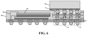
- FIG. 4 is a schematic structural diagram of a semiconductor package according to another embodiment of the disclosure.
- the second base plate 30 is not located above the first semiconductor structure 20, but directly located on the first base plate 10.
- the first surface 101 of the first base plate 10 further includes a fourth signal transmission region 14.
- the second base plate 30 is located on the fourth signal transmission region 14.
- the second signal transmission region 12 is electrically connected to the fourth signal transmission region 14.
- the fourth signal transmission region 14 is electrically connected to the first interconnection region 31.
- the fourth signal transmission region 14 and the first signal transmission region 11 are not connected to each other.
- the first interconnection region 31 is electrically connected to the second signal transmission region 12 by means of the second interconnection region 32
- the second signal transmission region 12 is electrically connected to the fourth signal transmission region 14, so that the fourth signal transmission region 14 is electrically connected to the first interconnection region by means of the second signal transmission region 12 and the second interconnection region 32.
- the manner of electrically connecting the first semiconductor structure 20 and the second base plate 30 with the first base plate 10 includes wire bonding and Through-Silicon-Via (TSV) interconnection.
- TSV Through-Silicon-Via
- the first semiconductor structure 20 and the second base plate 30 are electrically connected to the first base plate 10 by means of wire bonding.
- the first signal transmission region 11 and the second signal transmission region 12 are located at two opposite sides of the first base plate 10.
- the first semiconductor structure 20 has a first connection end 201.
- the first connection end 201 and the first signal transmission region 11 are located at the same side and connected to each other by using a lead wire 50.
- the second interconnection region 32 and the second signal transmission region 12 are located at the same side and connected to each other by using a lead wire 50.
- the wire bonding manner of electrically connecting the first semiconductor structure 20 with the first base plate 10 includes a hanging manner and a Film On Wire (FOW) manner.
- FOW Film On Wire
- wire bonding is performed by means of the hanging manner.
- the two adjacent first semiconductor chips 21 are connected to each other by means of an adhesive film 60.
- the adhesive film 60 does not cover the first connection end 201 and the lead wire 50 at the first semiconductor chip 21 at a layer below the adhesive film.
- the adhesive film is misaligned with the first semiconductor chip 21 at the layer below the adhesive film.
- wire bonding is performed by means of the FOW manner (not shown).
- the plurality of first semiconductor chips are aligned along a direction perpendicular to the first base plate) .
- the adhesive film between the two adjacent first semiconductor chips covers the first connection end and the lead wire at the first semiconductor chip at the layer below the adhesive film.
- the first semiconductor structure 20 is electrically connected to the first base plate 10 by means of TSV interconnection.
- the first semiconductor chip 21 includes a first chip connection pad 212 and a second chip connection pad 213 that are respectively located on the upper surface and the lower surface, and a first channel 211 that penetrates the first semiconductor chip 21 and connects the first chip connection pad 212 and the second chip connection pad 213.
- the first channel 211 includes a TSV.
- Electric connections between the two adjacent first semiconductor chips 21 and between the first semiconductor structure 20 and the first base plate 10 are achieved by means of the first chip connection pad 212, the second chip connection pad 213, the first channel 211 and a first solder ball 214.
- the first semiconductor structure 20 is connected to the first signal transmission region 11 in the direction perpendicular to the first base plate 10.
- the first semiconductor structure 20 is connected to the third signal transmission region 13 in the direction perpendicular to the first base plate 10.
- the first signal transmission region 11 is connected to the third signal transmission region 13.
- the first semiconductor structure is electrically connected to the first base plate by means of TSV interconnection, wire bonding is not required, so that the first signal transmission region and the third signal transmission region can be merged into one region.
- the second base plate 30 further includes a second interconnection surface 302 located on the other surface of the base 33.
- the base 33 has a channel 36 that connects the first interconnection region 31 and the second interconnection surface 302.
- the first interconnection region 31 is connected to the second signal transmission region 12 by means of the channel 36 in the direction perpendicular to the first base plate 10.
- the second base plate 30 includes a second connection pad 311 located in the first interconnection region 31, a fifth connection pad 37 located at the second interconnection surface 302 of the second base plate 30, and the channel 36 that penetrates the base 33 and connects the second connection pad 311 and the fifth connection pad 37.
- the channel 36 includes a TSV.
- the second base plate 30 is electrically connected to the first base plate 10 by means of the second connection pad 311, the channel 36, the fifth connection pad 37 and the second solder ball 38.
- the second base plate is electrically connected to the first base plate by means of TSV interconnection, wire bonding is not required, so that the second signal transmission region and the fourth signal transmission region can be merged into one region.
- the first base plate 10 in the direction perpendicular to the first base plate 10, has a first thickness.
- the second base plate 30 In a direction perpendicular to the second base plate 30, the second base plate 30 has a second thickness. The first thickness is less than the second thickness.
- the semiconductor package further includes a second package 70.
- the second package 70 has a contact surface 701.
- the second package 70 is connected to the first interconnection region 31 by means of the contact surface 701.
- the contact surface 701 of the second package 70 has a first contact structure 71.
- the first contact structure 71 has, in a direction perpendicular to the contact surface 701, a first height H protruding from the contact surface 701.
- the first height H is greater than the preset height h.
- the second package can be tightly connected to the second base plate.
- the second package after the second package is connected to the second base plate, there can be a gap between the second package and the filling layer. Therefore, the heat dissipation efficiency of a controller can be enhanced, and the impact of heat dissipation on chips can be reduced.
- the first connection pad 171 of the first base plate 10 has a second contact structure 18 protruding from the first base plate 10.
- the second contact structure 18 has, in the direction perpendicular to the first base plate 10, a second height protruding from the first base plate 10. The second height is less than or equal to the first height.
- the second package 70 includes a second semiconductor structure (not shown).
- the type of the second semiconductor structure is the same as or different from the type of the first semiconductor structure 20.
- the second semiconductor structure may be a Universal File Store (UFS) chip.
- UFS Universal File Store
- the second semiconductor structure in the second package 70 is connected to the second signal transmission region of the first base plate 10 by means of the second base plate 30.
- the first semiconductor structure 20 is connected to the first signal transmission region of the first base plate 10. In this way, transmission paths of the first semiconductor structure and the second semiconductor structure are distributed in different regions of the first base plate, so that mutual interference between the first semiconductor structure and the second semiconductor structure can be prevented, thereby enhancing the stability of signal transmission.
- the semiconductor package provided in the embodiments of the disclosure is applicable to UFS Multi Chip Package (UMCP) of a Package on Package (PoP) structure.
- UMCP UFS Multi Chip Package
- PoP Package on Package
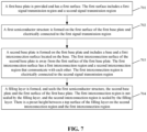
- Embodiments of the disclosure further provide a method for manufacturing a semiconductor package. Referring to FIG. 7 for details, as shown in the figure, the method includes the following operations.
- a first base plate has a first surface.
- the first surface includes a first signal transmission region and a second signal transmission region.
- a first semiconductor structure is formed on the first surface of the first base plate and electrically connected to the first signal transmission region.
- a second base plate is formed on the first base plate and includes a base and a first interconnection surface located on the base.
- the first interconnection surface of the second base plate is away from the first surface of the first base plate.
- the first interconnection surface has a first interconnection region and a second interconnection region that communicate with each other.
- the first interconnection region is electrically connected to the second signal transmission region.
- a filling layer is formed; the filling layer seals the first semiconductor structure, the second base plate and the first surface of the first base plate.
- the first interconnection region is not sealed by the filling layer, and the second interconnection region is sealed by the filling layer.
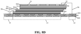
- FIG. 8A to FIG. 8G are schematic structural diagrams of a semiconductor package during manufacturing according to an embodiment of the disclosure.
- the first base plate 10 has a first surface 101.
- the first surface 101 includes a first signal transmission region 11 and a second signal transmission region 12.
- the first base plate 10 includes a first base 15, and a first upper insulating dielectric layer 16 and a first lower insulating dielectric layer 17 that are respectively located on an upper surface and lower surface of the first base 15.
- the first base 15 may be a silicon substrate, a germanium substrate, a silicon germanium substrate, a silicon carbide substrate, a Silicon On Insulator (SOI) substrate, or a Germanium On Insulator (GOI) substrate, or may be a substrate including other element semiconductors or compound semiconductors, such as a glass substrate or a III-V compound substrates (for example, a gallium nitride substrate or a gallium arsenide substrate), or may be a laminated structure such as Si/SiGe, or may be other epitaxial structures such as Silicon Germanium On Insulator (SGOI).
- SOI Silicon On Insulator
- GOI Germanium On Insulator
- the first upper insulating dielectric layer 16 and the first lower insulating dielectric layer 17 may be solder mask layers.
- materials of the first upper insulating dielectric layer 16 and the first lower insulating dielectric layer 17 may be green paint.
- the first base plate 10 has a second surface 102 facing away from the first surface 101. There is a circuit channel 151 between the first surface 101 and the second surface 102. The second surface 102 of the first base plate 10 has a plurality of first connection pads 171.
- the first surface of the first base plate 10 has a plurality of sixth connection pads 161.
- the circuit channel 151 connects the sixth connection pad 161 and the first connection pad 171.
- the first signal transmission region 11 of the first base plate 10 has a plurality of fourth connection pads 111.
- An area of the fourth connection pad 111 is less than or equal to the area of the first connection pad 171.
- the first surface 101 of the first base plate 10 includes a first signal transmission region 11 and a second signal transmission region 12.
- the first signal transmission region 11 is electrically connected to the first semiconductor structure 20 formed subsequently.
- the second signal transmission region 12 is electrically connected to the second base plate 30 formed subsequently.
- the first surface 101 of the first base plate 10 further includes a third signal transmission region 13 located between the first signal transmission region 11 and the second signal transmission region 12.
- the first semiconductor structure 20 formed subsequently is located on the third signal transmission region 13.
- the first base plate 10 further includes a fourth signal transmission region 14.
- the second base plate 30 formed subsequently is located on the fourth signal transmission region 14.
- the second signal transmission region 12 is electrically connected to the fourth signal transmission region 14.
- the first semiconductor structure 20 includes a plurality of first semiconductor chips 21 that are successively stacked in a direction perpendicular to the first base plate 10.
- the first semiconductor structure 20 is also connected to the first base plate 10 by means of the adhesive film 60.
- the second base plate 30 includes a base 33 and a first interconnection surface 301 located on the base 33.
- the first interconnection surface 301 of the second base plate 10 is away from the first surface 101 of the first base plate 10.
- the first interconnection surface 301 has a first interconnection region 31 and a second interconnection region 32 that communicate with each other.
- the first interconnection region 31 is electrically connected to the second signal transmission region 12.
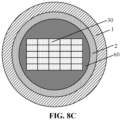
- a carrier band 2 is pasted on a circular ring 1.
- the adhesive film 60 is then pasted on the carrier band 2.
- the second base plate is pasted on the adhesive film 60.
- the second base plate is in an entire strip shape.
- the second base plate is cut to form units one by one shown in FIG. 8C .
- the second base plate 30 is formed on the first semiconductor structure 20.
- an adhesive layer 60 is formed on the first semiconductor structure 20. Then, the single second base plate formed in FIG. 8C is pasted on the first semiconductor structure 20.
- the second base plate 30 is not formed on the first semiconductor structure 20, but directly formed on the first base plate 10.
- the second base plate 30 includes a base 33, and an upper insulating dielectric layer 34 and a lower insulating dielectric layer 35 that are respectively located on an upper surface and lower surface of the base 33.
- the base 33 may be a silicon substrate, a germanium substrate, a silicon germanium substrate, a silicon carbide substrate, an SOI substrate, or a GOI substrate, or may be a substrate including other element semiconductors or compound semiconductors, such as a glass substrate or a III-V compound substrates (for example, a gallium nitride substrate or a gallium arsenide substrate), or may be a laminated structure such as Si/SiGe, or may be other epitaxial structures such as SGOI.
- the upper insulating dielectric layer 34 and the lower insulating dielectric layer 35 may be solder mask layers.
- materials of the upper insulating dielectric layer 34 and the lower insulating dielectric layer 35 may be green paint.
- the first interconnection region 31 of the second base plate 30 has a plurality of second connection pads 311. An area of the second connection pad 311 is greater than or equal to an area of the first connection pad 171.
- a contact area when the second package is in contact with the second connection pad 311 can be enlarged. If the contact area is relatively small, it is very difficult to dismount after soldering, so that follow-up disassembly and reassembly can be realized by enlarging the contact area.
- the second interconnection region 32 of the second base plate 30 has a plurality of third connection pads 321.
- An area of the third connection pad 321 is less than the area of the second connection pad 311.
- the number of the third connection pads 321 is greater than the number of the second connection pads 311.
- the third connection pad carries the interconnection between the second package and the first base plate, so that the layout design is more flexible.
- the base 33 of the second base plate 30 has an electromagnetic shielding layer (not shown). By disposing the electromagnetic shielding layer in the base of the second base plate, information interference between the second package and the first semiconductor structure can be prevented from affecting the operation of devices.
- the first semiconductor structure 20 is electrically connected to the second base plate 30 and the first base plate 10 by means of wire bonding.
- the first signal transmission region 11 and the second signal transmission region 12 are located at two opposite sides of the first base plate 10.
- the first semiconductor structure 20 has a first connection end 201.
- the first connection end 201 and the first signal transmission region 11 are located at the same side and connected to each other by using a lead wire 50.
- the second interconnection region 32 and the second signal transmission region 12 are located at the same side and connected to each other by using a lead wire 50.
- the first semiconductor structure 20 and the second base plate 30 are electrically connected to the first base plate 10 by means of TSV interconnection.
- the first semiconductor chip 21 includes a first chip connection pad 212 and a second chip connection pad 213 that are respectively located on the upper surface and the lower surface, and a first channel 211 that penetrates the first semiconductor chip 21 and connects the first chip connection pad 212 and the second chip connection pad 213.
- the first channel 211 includes a TSV.
- Electric connections between two adjacent ones of the first semiconductor chips 21 and between the first semiconductor structure 20 and the first base plate 10 are achieved by means of the first chip connection pad 212, the second chip connection pad 213, the first channel 211 and a first solder ball 214.
- the second base plate 30 further includes a second interconnection surface 302 located on the other surface of the base 33.
- the base 33 has a channel 36 that connects the first interconnection region 31 and the second interconnection surface 302.
- the first interconnection region 31 is connected to the second signal transmission region 12 by means of the channel 36 in the direction perpendicular to the first base plate 10.
- the second base plate 30 includes a second connection pad 311 located in the first interconnection region 31, a fifth connection pad 37 located at the second interconnection surface 302 of the second base plate 30, and the channel 36 that penetrates the base 33 and connects the second connection pad 311 and the fifth connection pad 37.
- the channel 36 includes a TSV. Also, there is a second solder ball 38 between the second base plate 30 and the first base plate 10.
- the second base plate 30 is electrically connected to the first base plate 10 by means of the second connection pad 311, the channel 36, the fifth connection pad 37 and the second solder ball 38.
- the filling layer 40 seals the first semiconductor structure 20, the second base plate 30 and the first surface 101 of the first base plate 10.
- the first interconnection region 31 is not sealed by the filling layer 40
- the second interconnection region 32 is sealed by the filling layer 40.
- a first packaging mold 91 is formed.
- the first packaging mold 91 includes a first portion 911 and second portions 912 located on two sides of the first portion 911, and a third portions 913 that connect the first portion 911 and the second portions 912.
- a surface of the second portion 912 is higher than a surface of the first portion 911.
- the surface of the second portion 912 and the surface of the first portion 911 are both parallel to a surface of the base plate 10.
- the first portion 911 is located on the first interconnection region 31 of the second base plate 30.
- the method further includes forming a second packaging mold 92.
- the second packaging mold 92 is located below the first base plate 10 and is parallel to the surface of the first base plate 10.
- a filling layer 40 is formed. After the filling layer 40 is formed, the method further includes removing the first packaging mold 91 and the second packaging mold 92, so as to expose the first interconnection region 31 that is covered by the first portion 911.
- a second contact structure 18 protruding the first base plate 10 is formed on the first connection pad 171 of the first base plate 10.
- the second contact structure 18 includes a conductive material.
- a second package 70 is formed.
- the second package 70 has a contact surface 701.
- the second package 70 is connected to the first interconnection region 31 by means of the contact surface 701.
- the contact surface 701 of the second package 70 has a first contact structure 71.
- the first contact structure 71 has, in a direction perpendicular to the contact surface 701, a first height H protruding from the contact surface 701.
- the first height H is greater than the preset height h.
- the second contact structure 18 on the first base plate 10 has, in a direction perpendicular to the first base plate 10, a second height protruding from the first base plate 10.
- the second height is less than or equal to the first height.
- the second package 70 includes a second semiconductor structure (not shown).
- the type of the second semiconductor structure is the same as or different from the type of the first semiconductor structure 20.
- subsequent other semiconductor structures may be connected to the first semiconductor structure and the first base plate by means of the first interconnection region of the second base plate. Therefore, the connection among the semiconductor structures of different types or different specifications can be realized, so as to cause a combination among different semiconductor structures to be more flexible.
- first semiconductor structure and subsequent other semiconductor structures connected to the first semiconductor structure are packaged independently, test and failure analysis are easier to perform. Since there is the preset height between the first interconnection region of the second base plate and the top surface of the filling layer, other semiconductor structures may be placed on the first interconnection region, within a region enclosed by the filling layer, so that the height and size of the entire structure can be reduced.
Landscapes
- Internal Circuitry In Semiconductor Integrated Circuit Devices (AREA)
- Physics & Mathematics (AREA)
- Health & Medical Sciences (AREA)
- Electromagnetism (AREA)
- Toxicology (AREA)
- Geometry (AREA)
Abstract
Description
- The disclosure is based upon and claims priority to
Chinese Patent Application No. 202210806565.3, filed on July 8, 2022 - The disclosure relates to the technical field of semiconductors, and in particular, to a semiconductor package.
- All sectors, industries and regions continually require lighter, faster, smaller, more functional, more reliable and more cost-effective products for the electronics industry. In order to meet these growing requirements of many different consumers, more circuits are required to be integrated to provide required functions. In almost all applications, there is a growing requirement for reducing sizes, enhancing performance and improving the functions of the integrated circuits.
- In view of this, an embodiment of the disclosure provides a semiconductor package.
- A first aspect of the embodiments of the disclosure provides a semiconductor package, including a first base plate, a first semiconductor structure, a second base plate and a filling layer.
- The first base plate has a first surface. The first surface includes a first signal transmission region and a second signal transmission region.
- The first semiconductor structure is located on the first surface of the first base plate and electrically connected to the first signal transmission region.
- The second base plate is located on the first base plate and includes a base and a first interconnection surface located on the base. The first interconnection surface of the second base plate is away from the first surface of the first base plate. The first interconnection surface has a first interconnection region and a second interconnection region that communicate with each other. The first interconnection region is electrically connected to the second signal transmission region.
- The filling layer seals the first semiconductor structure, the second base plate and the first surface of the first base plate. The first interconnection region is not sealed by the filling layer, and the second interconnection region is sealed by the filling layer. There is a preset height between a top surface of the filling layer on the second interconnection region and the first interconnection region.
- In some embodiments, the first surface of the first base plate further includes a third signal transmission region located between the first signal transmission region and the second signal transmission region. The first semiconductor structure is located on the third signal transmission region.
- In some embodiments, the first surface of the first base plate further includes a fourth signal transmission region. The second base plate is located on the fourth signal transmission region. The second signal transmission region is electrically connected to the fourth signal transmission region.
- In some embodiments, the second base plate is located on the first semiconductor structure. The first interconnection region is electrically connected to the second signal transmission region by means of the second interconnection region. The third signal transmission region includes a first signal sub-region and a second signal sub-region. The first signal sub-region is connected to the first signal transmission region and located in a close region of the first signal transmission region. The second signal sub-region is connected to the second signal transmission region and located in a close region of the second signal transmission region.
- In some embodiments, the fourth signal transmission region is electrically connected to the first interconnection region.
- In some embodiments, the first signal transmission region and the second signal transmission region are located at two opposite sides of the first base plate. The first semiconductor structure has a first connection end. The first connection end and the first signal transmission region are located at the same side and connected to each other by using a lead wire. The second interconnection region and the second signal transmission region are located at the same side and connected to each other by using a lead wire.
- In some embodiments, the first semiconductor structure is connected to the first signal transmission region in a direction perpendicular to the first base plate.
- In some embodiments, the first semiconductor structure is connected to the third signal transmission region in the direction perpendicular to the first base plate. The first signal transmission region is connected to the third signal transmission region.
- In some embodiments, the second base plate further includes a second interconnection surface located on the other surface of the base. The base has a channel that connects the first interconnection region and the second interconnection surface. The first interconnection region is connected to the second signal transmission region by means of the channel in a direction perpendicular to the first base plate.
- In some embodiments, the base of the second base plate has an electromagnetic shielding layer.
- In some embodiments, there is an electromagnetic shielding structure between the first signal sub-region of the first base plate and the second signal sub-region.
- In some embodiments, the first base plate has a second surface facing away from the first surface. There is a circuit channel between the first surface and the second surface. The second surface of the first base plate has a plurality of first connection pads.
- The first interconnection region of the second base plate has a plurality of second connection pads. An area of the second connection pad is greater than or equal to an area of the first connection pad.
- In some embodiments, the second interconnection region of the second base plate has a plurality of third connection pads. An area of the third connection pad is less than the area of the second connection pad.
- In some embodiments, the first signal transmission region of the first base plate has a plurality of fourth connection pads. An area of the fourth connection pad is less than or equal to the area of the first connection pad.
- In some embodiments, the number of the third connection pads is greater than the number of the second connection pads.
- In some embodiments, in a direction perpendicular to the first base plate, the first base plate has a first thickness. In a direction perpendicular to the second base plate, the second base plate has a second thickness. The first thickness is less than the second thickness.
- In some embodiments, the semiconductor package further includes a second package. The second package has a contact surface. The second package is connected to the first interconnection region by means of the contact surface.
- In some embodiments, the contact surface of the second package has a first contact structure. The first contact structure has, in a direction perpendicular to the contact surface, a first height protruding from the contact surface. The first height is greater than the preset height.
- In some embodiments, the first connection pad of the first base plate has a second contact structure protruding from the first base plate. The second contact structure has, in a direction perpendicular to the first base plate, a second height protruding from the first base plate. The second height is less than or equal to the first height.
- In some embodiments, the second package includes a second semiconductor structure. The type of the second semiconductor structure is the same as or different from the type of the first semiconductor structure.
- In the embodiments of the disclosure, through the arrangement of the second base plate, subsequent other semiconductor structures may be connected to the first semiconductor structure and the first base plate by means of the first interconnection region of the second base plate. Therefore, the connection among the semiconductor structures of different types or different specifications can be realized, so as to cause a combination among different semiconductor structures to be more flexible. In addition, since the first semiconductor structure and subsequent other semiconductor structures connected to the first semiconductor structure are packaged independently, test and failure analysis are easier to perform. Since there is the preset height between the first interconnection region of the second base plate and the top surface of the filling layer, other semiconductor structures may be placed on the first interconnection region, within a region enclosed by the filling layer, so that the height and size of the entire structure can be reduced.
- In order to more clearly illustrate the technical solutions in the embodiments of the disclosure or conventional technologies, the drawings used in the technical description of the embodiments will be briefly described below. It is apparent that the drawings in the following descriptions are merely some embodiments of the disclosure. Other drawings can be obtained from those skilled in the art according to these drawings without any creative work.
-
FIG. 1 is a schematic structural diagram of a semiconductor package according to an embodiment of the disclosure. -
FIG. 2 is a schematic structural diagram of a first base plate according to an embodiment of the disclosure. -
FIG. 3 is a schematic structural diagram of a second base plate according to an embodiment of the disclosure. -
FIG. 4 to FIG. 6 are other examples of a semiconductor package according to an embodiment of the disclosure. -
FIG. 7 is a schematic flowchart of a method for manufacturing a semiconductor package according to an embodiment of the disclosure. -
FIG. 8A to FIG. 8G are schematic structural diagrams of a semiconductor package during manufacturing according to an embodiment of the disclosure. -
- 1-Circular ring; 2-Carrier band;
- 10-First base plate; 101-First surface; 102-Second surface; 11-First signal transmission region; 12-Second signal transmission region; 13-Third signal transmission region; 131-First signal sub-region; 132-Second signal sub-region; 14-Fourth signal transmission region; 15-First base; 16-First upper insulating dielectric layer; 17-First lower insulating dielectric layer; 18-Second contact structure; 111-Fourth connection pad; 151-Circuit channel; 161-Sixth connection pad; 171-First connection pad;
- 20-First semiconductor structure; 21-First semiconductor chip; 201-First connection end; 211-First channel; 212-First chip connection pad; 213-Second chip connection pad; 214-First solder ball;
- 30-Second base plate; 31-First interconnection region; 32-Second interconnection region; 33-Base; 34-Upper insulating dielectric layer; 35-Lower insulating dielectric layer; 36-Channel; 37-Fifth connection pad; 38-Second solder ball; 301-First interconnection surface; 302-Second interconnection surface; 311-Second connection pad; 321-Third connection pad;
- 40-Filling layer;
- 50-Lead wire;
- 60-Adhesive film;
- 70-Second package; 71-First contact structure; 701-Contact surface;
- 91-First packaging mold; 911-First portion; 912-Second portion; 913-Third portion; 92-Second packaging mold.
- Exemplary embodiments disclosed in the disclosure are described in more detail with reference to drawings. Although the exemplary embodiments of the disclosure are shown in the drawings, it should be understood that the disclosure may be implemented in various forms and should not be limited by the specific embodiments described here. On the contrary, these embodiments are provided for more thorough understanding of the disclosure, and to fully convey a scope disclosed in the embodiments of the disclosure to a person skilled in the art.
- In the following descriptions, a lot of specific details are given in order to provide the more thorough understanding of the disclosure. However, it is apparent to a person skilled in the art that the disclosure may be implemented without one or more of these details. In other examples, in order to avoid confusion with the disclosure, some technical features well-known in the field are not described. Namely, all the features of the actual embodiments are not described here, and well-known functions and structures are not described in detail.
- In the drawings, the sizes of a layer, a region, and an element and their relative sizes may be exaggerated for clarity. The same reference sign represents the same element throughout.
- It should be understood that while the element or the layer is referred to as being "on", "adjacent to", "connected to" or "coupled to" other elements or layers, it may be directly on the other elements or layers, adjacent to, connected or coupled to the other elements or layers, or an intermediate element or layer may be existent. In contrast, while the element is referred to as being "directly on", "directly adjacent to", "directly connected to" or "directly coupled to" other elements or layers, the intermediate element or layer is not existent. It should be understood that although terms first, second, third and the like may be used to describe various elements, components, regions, layers and/or sections, these elements, components, regions, layers and/or sections should not be limited by these terms. These terms are only used to distinguish one element, component, region, layer or section from another element, component, region, layer or section. Therefore, without departing from the teaching of the disclosure, a first element, component, region, layer or section discussed below may be represented as a second element, component, region, layer or section. While the second element, component, region, layer or section is discussed, it does not mean that the first element, component, region, layer or section is necessarily existent in the disclosure.
- Spatial relation terms, such as "under", "below", "lower", "underneath", "above", "upper" and the like, may be used here for conveniently describing so that a relationship between one element or feature shown in the drawings and other elements or features is described. It should be understood that in addition to orientations shown in the drawings, the spatial relationship terms are intended to further include the different orientations of a device in use and operation. For example, if the device in the drawings is turned over, then the elements or the features described as "below" or "underneath" or "under" other elements may be oriented "on" the other elements or features. Therefore, the exemplary terms "below" and "under" may include two orientations of up and down. The device may be otherwise oriented (rotated by 90 degrees or other orientations) and the spatial descriptions used here are interpreted accordingly.
- A purpose of the terms used here is only to describe the specific embodiments and not as limitation to the disclosure. While used here, singular forms of "a", "an" and "said/the" are also intended to include plural forms, unless the context clearly indicates another mode. It should also be understood that terms "composition" and/or "including", while used in the description, determine the existence of the described features, integers, steps, operations, elements and/or components, but do not exclude the existence or addition of one or more other features, integers, steps, operations, elements, components, and/or groups. As used herein, a term "and/or" includes any and all combinations of related items listed.
- In order to understand the disclosure thoroughly, detailed steps and detailed structures are presented in the following description, so as to explain the technical solutions of the disclosure. Preferred embodiments of the disclosure are described in detail below; however, the disclosure may also have other implementations in addition to these detailed descriptions.
- A current semiconductor package technology generally uses a discrete method or a UFS Multi Chip Package (UMCP) method. The discrete method is, for example, to distribute a DRAM chip and an NAND chip for package. The UMCP is, for example, to package a memory chip and a control chip in the same package structure. Packaging by means of the discrete method causes the package structure to occupy a large area of a PCB, and the UMCP method may cause difficult test and failure analysis and poor heat dissipation of a controller. In addition, chips of different capacities cannot be flexibly combined.
- Based on this, embodiments of the disclosure provide a semiconductor package.
FIG. 1 is a schematic structural diagram of a semiconductor package according to an embodiment of the disclosure. - Referring to
FIG. 1 , the semiconductor package includes afirst base plate 10, afirst semiconductor structure 20, asecond base plate 30 and afilling layer 40. - The
first base plate 10 has afirst surface 101. Thefirst surface 101 includes a firstsignal transmission region 11 and a secondsignal transmission region 12. - The
first semiconductor structure 20 is located on thefirst surface 101 of thefirst base plate 10 and electrically connected to the firstsignal transmission region 11. - The
second base plate 30 is located above thefirst base plate 10 and includes abase 33 and afirst interconnection surface 301 located on thebase 33. Thefirst interconnection surface 301 of thesecond base plate 30 is away from thefirst surface 101 of thefirst base plate 10. Thefirst interconnection surface 301 has afirst interconnection region 31 and asecond interconnection region 32 that communicate with each other. Thefirst interconnection region 31 is electrically connected to the secondsignal transmission region 12. - The filling
layer 40 seals thefirst semiconductor structure 20, thesecond base plate 30 and thefirst surface 101 of thefirst base plate 10. Thefirst interconnection region 31 is not sealed by the fillinglayer 40, and thesecond interconnection region 32 is sealed by the fillinglayer 40. There is a preset height h between a top surface of thefilling layer 40 on thesecond interconnection region 32 and thefirst interconnection region 31. - Through the arrangement of the second base plate, subsequent other semiconductor structures can be connected to the first semiconductor structure and the first base plate by the first interconnection region on the second base plate. By doing so, the connection among the semiconductor structures of different types or different specifications can be realized, a combination among different semiconductor structures can be more flexible. In addition, since the first semiconductor structure and subsequent other semiconductor structures connected to the first semiconductor structure are packaged independently, test and failure analysis are easier to perform. Since there is the preset height between the first interconnection region of the second base plate and the top surface of the filling layer, other semiconductor structures may be placed on the first interconnection region, within a region enclosed by the filling layer, so that the height and size of the entire structure can be reduced.
-
FIG. 2 is a schematic structural diagram of a first base plate according to an embodiment of the disclosure. - In some embodiments, the
first base plate 10 may be a Printed Circuit Board (PCB) or a redistribution base plate. - As shown in
FIG. 2 , thefirst base plate 10 includes afirst base 15, and a first upper insulatingdielectric layer 16 and a first lower insulatingdielectric layer 17 that are respectively located on an upper surface and lower surface of thefirst base 15. - The
first base 15 may be a silicon substrate, a germanium substrate, a silicon germanium substrate, a silicon carbide substrate, a Silicon On Insulator (SOI) substrate, or a Germanium On Insulator (GOI) substrate, or may be a substrate including other element semiconductors or compound semiconductors, such as a glass substrate or a III-V compound substrates (for example, a gallium nitride substrate or a gallium arsenide substrate), or may be a laminated structure such as Si/SiGe, or may be other epitaxial structures such as Silicon Germanium On Insulator (SGOI). - The first upper insulating
dielectric layer 16 and the first lower insulatingdielectric layer 17 may be solder mask layers. For example, materials of the first upper insulatingdielectric layer 16 and the first lower insulatingdielectric layer 17 may be green paint. - In an embodiment, the
first base plate 10 has asecond surface 102 facing away from thefirst surface 101. There arecircuit channels 151 between thefirst surface 101 and thesecond surface 102. Thesecond surface 102 of thefirst base plate 10 has a plurality offirst connection pads 171. - The first surface of the
first base plate 10 has a plurality ofsixth connection pads 161. Thecircuit channel 151 connects thesixth connection pad 161 and thefirst connection pad 171. - In an embodiment, the first
signal transmission region 11 of thefirst base plate 10 has a plurality offourth connection pads 111. An area of thefourth connection pad 111 is less than or equal to the area of thefirst connection pad 171. In this embodiment, by means of the design that the area of thefourth connection pad 111 is less than the area of thefirst connection pad 171, more efficient signal transmission efficiency between thefirst semiconductor structure 20 and the firstsignal transmission region 11 of thefirst base plate 10 can be achieved, and a chip area can be reduced. In addition, by means of the design that the area of thefirst connection pad 171 is greater than that of thefourth connection pad 111, the conductive efficiency and heat conduction efficiency between thefirst semiconductor structure 20 and thefirst base plate 10 can be enhanced. The first signal transmission region of thefirst base plate 10 is electrically connected to the second surface. - The
first connection pad 171 of thefirst base plate 10 has asecond contact structure 18 protruding from thefirst base plate 10. - The
second contact structure 18 may electrically connect the semiconductor package to an external apparatus, so that at least one of a control signal, a power signal or a grounding signal that are used to operate the first semiconductor structure may be received from the external apparatus, or a data signal to be stored in the first semiconductor structure may be received from the external apparatus. Alternatively, data in the first semiconductor structure may also be provided to the external apparatus. - The
second contact structure 18 includes a conductive material. In this embodiment of the disclosure, thesecond contact structure 18 is a solder ball. It is understandable that, a shape of the second contact structure provided in the embodiments of the disclosure is only a specific and feasible implementation in the embodiments of the disclosure, and does not constitute a limitation of the disclosure. The second contact structure may also be a structure with other shapes. The number, spacing, and location of the second contact structures are not limited to any specific arrangement, and various modifications may be made. - The
first surface 101 of thefirst base plate 10 includes a firstsignal transmission region 11 and a secondsignal transmission region 12. The firstsignal transmission region 11 is electrically connected to thefirst semiconductor structure 20. The secondsignal transmission region 12 is electrically connected to thesecond base plate 30. - In an embodiment, the first
signal transmission region 11 and the secondsignal transmission region 12 are not connected to each other. - In an embodiment, the
first surface 101 of thefirst base plate 10 further includes a thirdsignal transmission region 13 located between the firstsignal transmission region 11 and the secondsignal transmission region 12. Thefirst semiconductor structure 20 is located on the thirdsignal transmission region 13. In this embodiment, by disposing thefirst semiconductor structure 20 right above the thirdsignal transmission region 13, the firstsignal transmission region 11 is located outside thefirst semiconductor structure 20, so that the connection stability between the firstsignal transmission region 11 and thefirst semiconductor structure 20 can be increased. - In an embodiment, an area of a distribution region of the first
signal transmission region 11 on thefirst base plate 10 may be less than an area of a distribution region of the thirdsignal transmission region 13 on thefirst base plate 10, so that a lateral dimension of a first package can be decreased, and an integration level can be enhanced. - The
first semiconductor structure 20 includes a plurality offirst semiconductor chips 21 that are successively stacked in a direction perpendicular to thefirst base plate 10. In this embodiment, by means of successively stacking the plurality of first semiconductor chips upwards, a horizontal area of the semiconductor package can be saved. The first semiconductor chip may be a DRAM chip. - In an embodiment, as shown in
FIG. 1 andFIG. 2 , thesecond base plate 30 is located on thefirst semiconductor structure 20. Thefirst interconnection region 31 is electrically connected to the secondsignal transmission region 12 by means of thesecond interconnection region 32. The thirdsignal transmission region 13 includes afirst signal sub-region 131 and asecond signal sub-region 132. Thefirst signal sub-region 131 is connected to the firstsignal transmission region 11 and located in a close region of the firstsignal transmission region 11. Thesecond signal sub-region 132 is connected to the secondsignal transmission region 12 and located in a close region of the secondsignal transmission region 12. - In an embodiment, the
first signal sub-region 131 and thesecond signal sub-region 132 are not connected to each other. - In an embodiment, there is an electromagnetic shielding structure (not shown) between the
first signal sub-region 131 and thesecond signal sub-region 132 of thefirst base plate 10. - Since the
first signal sub-region 131 is connected to the firstsignal transmission region 11, thesecond signal sub-region 132 is connected to the second signal transmission region, the first signal transmission region is connected to the first semiconductor structure, and the second signal transmission region is indirectly connected to a second package by being connected to the second base plate, by disposing the electromagnetic shielding structure between the first signal sub-region and the second signal sub-region, signal interference between the first semiconductor structure and the second package can be prevented. -
FIG. 3 is a schematic structural diagram of a second base plate according to an embodiment of the disclosure. - As shown in
FIG. 3 , thesecond base plate 30 includes abase 33, and an upper insulatingdielectric layer 34 and a lower insulatingdielectric layer 35 that are respectively located on an upper surface and lower surface of thebase 33. - The base 33 may be a silicon substrate, a germanium substrate, a silicon germanium substrate, a silicon carbide substrate, an SOI substrate, or a GOI substrate, or may be a substrate including other element semiconductors or compound semiconductors, such as a glass substrate or a III-V compound substrates (for example, a gallium nitride substrate or a gallium arsenide substrate), or may be a laminated structure such as Si/SiGe, or may be other epitaxial structures such as SGOI.
- The upper insulating
dielectric layer 34 and the lower insulatingdielectric layer 35 may be solder mask layers. For example, materials of the upper insulatingdielectric layer 34 and the lower insulatingdielectric layer 35 may be green paint. - The
first interconnection region 31 of thesecond base plate 30 has a plurality ofsecond connection pads 311. An area of thesecond connection pad 311 is greater than or equal to an area of thefirst connection pad 171. - By setting the area of the
second connection pad 311 to a larger area, a contact area when the second package is in contact with thesecond connection pad 311 can be enlarged. If the contact area is relatively small, it is very difficult to dismount after soldering, so that more convenient follow-up disassembly and reassembly can be realized by enlarging the contact area. - In an embodiment, the
second interconnection region 32 of thesecond base plate 30 has a plurality ofthird connection pads 321. An area of thethird connection pad 321 is less than the area of thesecond connection pad 311. - The number of the
third connection pads 321 is greater than the number of thesecond connection pads 311. - Since the second connection pad is required to be mated and connected to the second package subsequently, the layout design is relatively fixed. The third connection pad carries the interconnection between the second package and the first base plate, so that the layout design is more flexible. By designing the third connection pad to have a larger number and a smaller area, the signal transmission efficiency can be enhanced, and the integration level of the first package can be increased.
- In an embodiment, the
base 33 of thesecond base plate 30 has an electromagnetic shielding layer (not shown). By disposing the electromagnetic shielding layer in the base of the second base plate, information interference between the second package and the first semiconductor structure can be prevented from affecting the operation of devices. -
FIG. 4 is a schematic structural diagram of a semiconductor package according to another embodiment of the disclosure. - As shown in
FIG. 4 , in this embodiment, thesecond base plate 30 is not located above thefirst semiconductor structure 20, but directly located on thefirst base plate 10. - In an embodiment, the
first surface 101 of thefirst base plate 10 further includes a fourthsignal transmission region 14. Thesecond base plate 30 is located on the fourthsignal transmission region 14. The secondsignal transmission region 12 is electrically connected to the fourthsignal transmission region 14. - In an embodiment, the fourth
signal transmission region 14 is electrically connected to thefirst interconnection region 31. - In an embodiment, the fourth
signal transmission region 14 and the firstsignal transmission region 11 are not connected to each other. - Specifically, the
first interconnection region 31 is electrically connected to the secondsignal transmission region 12 by means of thesecond interconnection region 32, and the secondsignal transmission region 12 is electrically connected to the fourthsignal transmission region 14, so that the fourthsignal transmission region 14 is electrically connected to the first interconnection region by means of the secondsignal transmission region 12 and thesecond interconnection region 32. - In this embodiment of the disclosure, the manner of electrically connecting the
first semiconductor structure 20 and thesecond base plate 30 with thefirst base plate 10 includes wire bonding and Through-Silicon-Via (TSV) interconnection. - Referring to
FIG. 1 , thefirst semiconductor structure 20 and thesecond base plate 30 are electrically connected to thefirst base plate 10 by means of wire bonding. - The first
signal transmission region 11 and the secondsignal transmission region 12 are located at two opposite sides of thefirst base plate 10. Thefirst semiconductor structure 20 has afirst connection end 201. Thefirst connection end 201 and the firstsignal transmission region 11 are located at the same side and connected to each other by using alead wire 50. Thesecond interconnection region 32 and the secondsignal transmission region 12 are located at the same side and connected to each other by using alead wire 50. - The wire bonding manner of electrically connecting the
first semiconductor structure 20 with thefirst base plate 10 includes a hanging manner and a Film On Wire (FOW) manner. - In the embodiment shown in
FIG. 1 , wire bonding is performed by means of the hanging manner. The two adjacentfirst semiconductor chips 21 are connected to each other by means of anadhesive film 60. Theadhesive film 60 does not cover thefirst connection end 201 and thelead wire 50 at thefirst semiconductor chip 21 at a layer below the adhesive film. The adhesive film is misaligned with thefirst semiconductor chip 21 at the layer below the adhesive film. - In some other embodiments, wire bonding is performed by means of the FOW manner (not shown). The plurality of first semiconductor chips are aligned along a direction perpendicular to the first base plate) . The adhesive film between the two adjacent first semiconductor chips covers the first connection end and the lead wire at the first semiconductor chip at the layer below the adhesive film.
- In other embodiments, referring to
FIG. 5 andFIG. 6 , thefirst semiconductor structure 20 is electrically connected to thefirst base plate 10 by means of TSV interconnection. - As shown in
FIG. 5 , thefirst semiconductor chip 21 includes a firstchip connection pad 212 and a secondchip connection pad 213 that are respectively located on the upper surface and the lower surface, and afirst channel 211 that penetrates thefirst semiconductor chip 21 and connects the firstchip connection pad 212 and the secondchip connection pad 213. Thefirst channel 211 includes a TSV. - Electric connections between the two adjacent
first semiconductor chips 21 and between thefirst semiconductor structure 20 and thefirst base plate 10 are achieved by means of the firstchip connection pad 212, the secondchip connection pad 213, thefirst channel 211 and afirst solder ball 214. - The
first semiconductor structure 20 is connected to the firstsignal transmission region 11 in the direction perpendicular to thefirst base plate 10. - The
first semiconductor structure 20 is connected to the thirdsignal transmission region 13 in the direction perpendicular to thefirst base plate 10. The firstsignal transmission region 11 is connected to the thirdsignal transmission region 13. - In this embodiment, since the first semiconductor structure is electrically connected to the first base plate by means of TSV interconnection, wire bonding is not required, so that the first signal transmission region and the third signal transmission region can be merged into one region.
- As shown in
FIG. 6 , thesecond base plate 30 further includes asecond interconnection surface 302 located on the other surface of thebase 33. Thebase 33 has achannel 36 that connects thefirst interconnection region 31 and thesecond interconnection surface 302. Thefirst interconnection region 31 is connected to the secondsignal transmission region 12 by means of thechannel 36 in the direction perpendicular to thefirst base plate 10. - The
second base plate 30 includes asecond connection pad 311 located in thefirst interconnection region 31, a fifth connection pad 37 located at thesecond interconnection surface 302 of thesecond base plate 30, and thechannel 36 that penetrates thebase 33 and connects thesecond connection pad 311 and the fifth connection pad 37. Thechannel 36 includes a TSV. There is also a second solder ball 38 between thesecond base plate 30 and thefirst base plate 10. - The
second base plate 30 is electrically connected to thefirst base plate 10 by means of thesecond connection pad 311, thechannel 36, the fifth connection pad 37 and the second solder ball 38. - In this embodiment, since the second base plate is electrically connected to the first base plate by means of TSV interconnection, wire bonding is not required, so that the second signal transmission region and the fourth signal transmission region can be merged into one region.
- In an embodiment, in the direction perpendicular to the
first base plate 10, thefirst base plate 10 has a first thickness. In a direction perpendicular to thesecond base plate 30, thesecond base plate 30 has a second thickness. The first thickness is less than the second thickness. Through such configuration, when the filling layer seals the first base plate and the second base plate, the warping of thesecond base plate 30 due to a difference between sizes of thefirst base plate 10 and thesecond base plate 30 can be prevented from affecting a sealing effect. - In an embodiment, the semiconductor package further includes a
second package 70. Thesecond package 70 has acontact surface 701. Thesecond package 70 is connected to thefirst interconnection region 31 by means of thecontact surface 701. - The
contact surface 701 of thesecond package 70 has afirst contact structure 71. Thefirst contact structure 71 has, in a direction perpendicular to thecontact surface 701, a first height H protruding from thecontact surface 701. The first height H is greater than the preset height h. - In this embodiment of the disclosure, by designing the first height to be greater than the preset height, the second package can be tightly connected to the second base plate. In addition, after the second package is connected to the second base plate, there can be a gap between the second package and the filling layer. Therefore, the heat dissipation efficiency of a controller can be enhanced, and the impact of heat dissipation on chips can be reduced.
- In an embodiment, referring to
FIG. 2 , thefirst connection pad 171 of thefirst base plate 10 has asecond contact structure 18 protruding from thefirst base plate 10. Thesecond contact structure 18 has, in the direction perpendicular to thefirst base plate 10, a second height protruding from thefirst base plate 10. The second height is less than or equal to the first height. Through such configuration, the second package using thefirst contact structure 71 as a support can be bonded to the first package more stably. - In an embodiment, the
second package 70 includes a second semiconductor structure (not shown). The type of the second semiconductor structure is the same as or different from the type of thefirst semiconductor structure 20. - For example, the second semiconductor structure may be a Universal File Store (UFS) chip.
- In the semiconductor package provided in the disclosure, the second semiconductor structure in the
second package 70 is connected to the second signal transmission region of thefirst base plate 10 by means of thesecond base plate 30. Thefirst semiconductor structure 20 is connected to the first signal transmission region of thefirst base plate 10. In this way, transmission paths of the first semiconductor structure and the second semiconductor structure are distributed in different regions of the first base plate, so that mutual interference between the first semiconductor structure and the second semiconductor structure can be prevented, thereby enhancing the stability of signal transmission. - The semiconductor package provided in the embodiments of the disclosure is applicable to UFS Multi Chip Package (UMCP) of a Package on Package (PoP) structure.
- Embodiments of the disclosure further provide a method for manufacturing a semiconductor package. Referring to
FIG. 7 for details, as shown in the figure, the method includes the following operations. - At S701, a first base plate is provided and has a first surface. The first surface includes a first signal transmission region and a second signal transmission region.
- At S702, a first semiconductor structure is formed on the first surface of the first base plate and electrically connected to the first signal transmission region.
- At S703, a second base plate is formed on the first base plate and includes a base and a first interconnection surface located on the base. The first interconnection surface of the second base plate is away from the first surface of the first base plate. The first interconnection surface has a first interconnection region and a second interconnection region that communicate with each other. The first interconnection region is electrically connected to the second signal transmission region.
- At S704, a filling layer is formed; the filling layer seals the first semiconductor structure, the second base plate and the first surface of the first base plate. The first interconnection region is not sealed by the filling layer, and the second interconnection region is sealed by the filling layer. There is a preset height between a top surface of the filling layer on the second interconnection region and the first interconnection region.
- The method for manufacturing a semiconductor package provided in the embodiments of the disclosure is further described in detail below with reference to specific embodiments.
-
FIG. 8A to FIG. 8G are schematic structural diagrams of a semiconductor package during manufacturing according to an embodiment of the disclosure. - Firstly, referring to
FIG. 8A , S701 of providing thefirst base plate 10 is executed. Thefirst base plate 10 has afirst surface 101. Thefirst surface 101 includes a firstsignal transmission region 11 and a secondsignal transmission region 12. - The
first base plate 10 includes afirst base 15, and a first upper insulatingdielectric layer 16 and a first lower insulatingdielectric layer 17 that are respectively located on an upper surface and lower surface of thefirst base 15. - The
first base 15 may be a silicon substrate, a germanium substrate, a silicon germanium substrate, a silicon carbide substrate, a Silicon On Insulator (SOI) substrate, or a Germanium On Insulator (GOI) substrate, or may be a substrate including other element semiconductors or compound semiconductors, such as a glass substrate or a III-V compound substrates (for example, a gallium nitride substrate or a gallium arsenide substrate), or may be a laminated structure such as Si/SiGe, or may be other epitaxial structures such as Silicon Germanium On Insulator (SGOI). - The first upper insulating
dielectric layer 16 and the first lower insulatingdielectric layer 17 may be solder mask layers. For example, materials of the first upper insulatingdielectric layer 16 and the first lower insulatingdielectric layer 17 may be green paint. - The
first base plate 10 has asecond surface 102 facing away from thefirst surface 101. There is acircuit channel 151 between thefirst surface 101 and thesecond surface 102. Thesecond surface 102 of thefirst base plate 10 has a plurality offirst connection pads 171. - The first surface of the
first base plate 10 has a plurality ofsixth connection pads 161. Thecircuit channel 151 connects thesixth connection pad 161 and thefirst connection pad 171. - In an embodiment, the first
signal transmission region 11 of thefirst base plate 10 has a plurality offourth connection pads 111. An area of thefourth connection pad 111 is less than or equal to the area of thefirst connection pad 171. - The
first surface 101 of thefirst base plate 10 includes a firstsignal transmission region 11 and a secondsignal transmission region 12. The firstsignal transmission region 11 is electrically connected to thefirst semiconductor structure 20 formed subsequently. The secondsignal transmission region 12 is electrically connected to thesecond base plate 30 formed subsequently. - In an embodiment, the
first surface 101 of thefirst base plate 10 further includes a thirdsignal transmission region 13 located between the firstsignal transmission region 11 and the secondsignal transmission region 12. Thefirst semiconductor structure 20 formed subsequently is located on the thirdsignal transmission region 13. - In some other embodiments, for example, as shown in
FIG. 4 , thefirst base plate 10 further includes a fourthsignal transmission region 14. Thesecond base plate 30 formed subsequently is located on the fourthsignal transmission region 14. The secondsignal transmission region 12 is electrically connected to the fourthsignal transmission region 14. - Next, referring to
FIG. 8B , S702 of forming thefirst semiconductor structure 20 on thefirst surface 101 of thefirst base plate 10 is executed. Thefirst semiconductor structure 20 is electrically connected to the firstsignal transmission region 11. - The
first semiconductor structure 20 includes a plurality offirst semiconductor chips 21 that are successively stacked in a direction perpendicular to thefirst base plate 10. - Two adjacent ones of the
first semiconductor chips 21 are connected to each other by means of anadhesive film 60. Thefirst semiconductor structure 20 is also connected to thefirst base plate 10 by means of theadhesive film 60. - Next, referring to
FIG. 8C andFIG. 8D , S703 of forming thesecond base plate 30 on thefirst base plate 10 is executed. Thesecond base plate 30 includes abase 33 and afirst interconnection surface 301 located on thebase 33. Thefirst interconnection surface 301 of thesecond base plate 10 is away from thefirst surface 101 of thefirst base plate 10. Thefirst interconnection surface 301 has afirst interconnection region 31 and asecond interconnection region 32 that communicate with each other. Thefirst interconnection region 31 is electrically connected to the secondsignal transmission region 12. - Specifically, referring to
FIG. 8C first, acarrier band 2 is pasted on acircular ring 1. Theadhesive film 60 is then pasted on thecarrier band 2. Then, the second base plate is pasted on theadhesive film 60. In this case, the second base plate is in an entire strip shape. The second base plate is cut to form units one by one shown inFIG. 8C . - Next, referring to
FIG. 8D , thesecond base plate 30 is formed on thefirst semiconductor structure 20. - Specifically, an
adhesive layer 60 is formed on thefirst semiconductor structure 20. Then, the single second base plate formed inFIG. 8C is pasted on thefirst semiconductor structure 20. - In some other embodiments, for example, as shown in
FIG. 4 , thesecond base plate 30 is not formed on thefirst semiconductor structure 20, but directly formed on thefirst base plate 10. - Referring to
FIG. 3 , thesecond base plate 30 includes abase 33, and an upper insulatingdielectric layer 34 and a lower insulatingdielectric layer 35 that are respectively located on an upper surface and lower surface of thebase 33. - The base 33 may be a silicon substrate, a germanium substrate, a silicon germanium substrate, a silicon carbide substrate, an SOI substrate, or a GOI substrate, or may be a substrate including other element semiconductors or compound semiconductors, such as a glass substrate or a III-V compound substrates (for example, a gallium nitride substrate or a gallium arsenide substrate), or may be a laminated structure such as Si/SiGe, or may be other epitaxial structures such as SGOI.
- The upper insulating
dielectric layer 34 and the lower insulatingdielectric layer 35 may be solder mask layers. For example, materials of the upper insulatingdielectric layer 34 and the lower insulatingdielectric layer 35 may be green paint. - The
first interconnection region 31 of thesecond base plate 30 has a plurality ofsecond connection pads 311. An area of thesecond connection pad 311 is greater than or equal to an area of thefirst connection pad 171. - By setting the area of the
second connection pad 311 to a larger area, a contact area when the second package is in contact with thesecond connection pad 311 can be enlarged. If the contact area is relatively small, it is very difficult to dismount after soldering, so that follow-up disassembly and reassembly can be realized by enlarging the contact area. - In an embodiment, the
second interconnection region 32 of thesecond base plate 30 has a plurality ofthird connection pads 321. An area of thethird connection pad 321 is less than the area of thesecond connection pad 311. - The number of the
third connection pads 321 is greater than the number of thesecond connection pads 311. - Since the second connection pad is required to be mated and connected to the second package subsequently, the layout design is relatively fixed. The third connection pad carries the interconnection between the second package and the first base plate, so that the layout design is more flexible. By designing the third connection pad to have a large number and a smaller area, the signal transmission efficiency can be enhanced.
- In an embodiment, the
base 33 of thesecond base plate 30 has an electromagnetic shielding layer (not shown). By disposing the electromagnetic shielding layer in the base of the second base plate, information interference between the second package and the first semiconductor structure can be prevented from affecting the operation of devices. - Continuously referring to
FIG. 8D , after thesecond base plate 30 is formed; thefirst semiconductor structure 20 is electrically connected to thesecond base plate 30 and thefirst base plate 10 by means of wire bonding. - The first
signal transmission region 11 and the secondsignal transmission region 12 are located at two opposite sides of thefirst base plate 10. Thefirst semiconductor structure 20 has afirst connection end 201. Thefirst connection end 201 and the firstsignal transmission region 11 are located at the same side and connected to each other by using alead wire 50. Thesecond interconnection region 32 and the secondsignal transmission region 12 are located at the same side and connected to each other by using alead wire 50. - In some other embodiments, the
first semiconductor structure 20 and thesecond base plate 30 are electrically connected to thefirst base plate 10 by means of TSV interconnection. - As shown in
FIG. 5 , thefirst semiconductor chip 21 includes a firstchip connection pad 212 and a secondchip connection pad 213 that are respectively located on the upper surface and the lower surface, and afirst channel 211 that penetrates thefirst semiconductor chip 21 and connects the firstchip connection pad 212 and the secondchip connection pad 213. Thefirst channel 211 includes a TSV. - Electric connections between two adjacent ones of the
first semiconductor chips 21 and between thefirst semiconductor structure 20 and thefirst base plate 10 are achieved by means of the firstchip connection pad 212, the secondchip connection pad 213, thefirst channel 211 and afirst solder ball 214. - As shown in
FIG. 6 , thesecond base plate 30 further includes asecond interconnection surface 302 located on the other surface of thebase 33. Thebase 33 has achannel 36 that connects thefirst interconnection region 31 and thesecond interconnection surface 302. Thefirst interconnection region 31 is connected to the secondsignal transmission region 12 by means of thechannel 36 in the direction perpendicular to thefirst base plate 10. - The
second base plate 30 includes asecond connection pad 311 located in thefirst interconnection region 31, a fifth connection pad 37 located at thesecond interconnection surface 302 of thesecond base plate 30, and thechannel 36 that penetrates thebase 33 and connects thesecond connection pad 311 and the fifth connection pad 37. Thechannel 36 includes a TSV. Also, there is a second solder ball 38 between thesecond base plate 30 and thefirst base plate 10. - The
second base plate 30 is electrically connected to thefirst base plate 10 by means of thesecond connection pad 311, thechannel 36, the fifth connection pad 37 and the second solder ball 38. - Next, referring to
FIG. 8E andFIG. 8F , S704 of forming thefilling layer 40 is executed. The fillinglayer 40 seals thefirst semiconductor structure 20, thesecond base plate 30 and thefirst surface 101 of thefirst base plate 10. Thefirst interconnection region 31 is not sealed by the fillinglayer 40, and thesecond interconnection region 32 is sealed by the fillinglayer 40. There is a preset height h between a top surface of thefilling layer 40 on thesecond interconnection region 32 and thefirst interconnection region 31. - Specifically, referring to
FIG. 8E first, afirst packaging mold 91 is formed. Thefirst packaging mold 91 includes afirst portion 911 andsecond portions 912 located on two sides of thefirst portion 911, and athird portions 913 that connect thefirst portion 911 and thesecond portions 912. A surface of thesecond portion 912 is higher than a surface of thefirst portion 911. The surface of thesecond portion 912 and the surface of thefirst portion 911 are both parallel to a surface of thebase plate 10. Thefirst portion 911 is located on thefirst interconnection region 31 of thesecond base plate 30. - The method further includes forming a
second packaging mold 92. Thesecond packaging mold 92 is located below thefirst base plate 10 and is parallel to the surface of thefirst base plate 10. - Next, referring to
FIG. 8F , by taking thefirst packaging mold 91 and thesecond packaging mold 92 as masks, afilling layer 40 is formed. After thefilling layer 40 is formed, the method further includes removing thefirst packaging mold 91 and thesecond packaging mold 92, so as to expose thefirst interconnection region 31 that is covered by thefirst portion 911. - Continuously referring to
FIG. 8F , after thefilling layer 40 is formed, asecond contact structure 18 protruding thefirst base plate 10 is formed on thefirst connection pad 171 of thefirst base plate 10. Thesecond contact structure 18 includes a conductive material. - Next, referring to
FIG. 8G , asecond package 70 is formed. Thesecond package 70 has acontact surface 701. Thesecond package 70 is connected to thefirst interconnection region 31 by means of thecontact surface 701. - The
contact surface 701 of thesecond package 70 has afirst contact structure 71. Thefirst contact structure 71 has, in a direction perpendicular to thecontact surface 701, a first height H protruding from thecontact surface 701. The first height H is greater than the preset height h. - In an embodiment, the
second contact structure 18 on thefirst base plate 10 has, in a direction perpendicular to thefirst base plate 10, a second height protruding from thefirst base plate 10. The second height is less than or equal to the first height. - In an embodiment, the
second package 70 includes a second semiconductor structure (not shown). The type of the second semiconductor structure is the same as or different from the type of thefirst semiconductor structure 20. - The above are only preferred embodiments of the disclosure, and are not used to limit the scope of protection of the disclosure. Any modifications, equivalent replacements and improvements and the like made within the spirit and principle of the disclosure shall be included within the scope of protection of the disclosure.
- In the embodiments of the disclosure, through the arrangement of the second base plate, subsequent other semiconductor structures may be connected to the first semiconductor structure and the first base plate by means of the first interconnection region of the second base plate. Therefore, the connection among the semiconductor structures of different types or different specifications can be realized, so as to cause a combination among different semiconductor structures to be more flexible. In addition, since the first semiconductor structure and subsequent other semiconductor structures connected to the first semiconductor structure are packaged independently, test and failure analysis are easier to perform. Since there is the preset height between the first interconnection region of the second base plate and the top surface of the filling layer, other semiconductor structures may be placed on the first interconnection region, within a region enclosed by the filling layer, so that the height and size of the entire structure can be reduced.
Claims (20)
- A semiconductor package, comprising:a first base plate, having a first surface, wherein the first surface comprises a first signal transmission region and a second signal transmission region;a first semiconductor structure, located on the first surface of the first base plate and electrically connected to the first signal transmission region;a second base plate, located on the first base plate and comprising a base and a first interconnection surface located on the base, wherein the first interconnection surface of the second base plate is away from the first surface of the first base plate, the first interconnection surface has a first interconnection region and a second interconnection region that communicate with each other, and the first interconnection region is electrically connected to the second signal transmission region; anda filling layer, sealing the first semiconductor structure, the second base plate and the first surface of the first base plate, wherein the first interconnection region is not sealed by the filling layer, the second interconnection region is sealed by the filling layer, and there is a preset height between a top surface of the filling layer on the second interconnection region and the first interconnection region.
- The semiconductor package of claim 1, wherein the first surface of the first base plate further comprises a third signal transmission region located between the first signal transmission region and the second signal transmission region; and the first semiconductor structure is located on the third signal transmission region.
- The semiconductor package of claim 2, wherein the first surface of the first base plate further comprises a fourth signal transmission region; the second base plate is located on the fourth signal transmission region; and the second signal transmission region is electrically connected to the fourth signal transmission region.
- The semiconductor package of claim 2, wherein the second base plate is located on the first semiconductor structure; the first interconnection region is electrically connected to the second signal transmission region by means of the second interconnection region; the third signal transmission region comprises a first signal sub-region and a second signal sub-region; the first signal sub-region is connected to the first signal transmission region and located in a close region of the first signal transmission region; and the second signal sub-region is connected to the second signal transmission region and located in a close region of the second signal transmission region.
- The semiconductor package of claim 3, wherein the fourth signal transmission region is electrically connected to the first interconnection region.
- The semiconductor package of claim 2, wherein the first signal transmission region and the second signal transmission region are located at two opposite sides of the first base plate; the first semiconductor structure has a first connection end; the first connection end and the first signal transmission region are located at a same side and connected to each other by using a lead wire; and the second interconnection region and the second signal transmission region are located at a same side and connected to each other by using a lead wire.
- The semiconductor package of claim 2, wherein the first semiconductor structure is connected to the first signal transmission region in a direction perpendicular to the first base plate.
- The semiconductor package of claim 7, wherein the first semiconductor structure is connected to the third signal transmission region in the direction perpendicular to the first base plate; and the first signal transmission region is connected to the third signal transmission region.
- The semiconductor package of claim 3, wherein the second base plate further comprises a second interconnection surface located on an other surface of the base; the base has a channel that connects the first interconnection region and the second interconnection surface; and the first interconnection region is connected to the second signal transmission region by means of the channel in a direction perpendicular to the first base plate.
- The semiconductor package of claim 1, wherein the base of the second base plate has an electromagnetic shielding layer.
- The semiconductor package of claim 4, wherein there is an electromagnetic shielding structure between the first signal sub-region of the first base plate and the second signal sub-region.
- The semiconductor package of claim 1, wherein the first base plate has a second surface facing away from the first surface; there is a circuit channel between the first surface and the second surface; the second surface of the first base plate has a plurality of first connection pads; and
wherein the first interconnection region of the second base plate has a plurality of second connection pads; and an area of a second connection pad is greater than or equal to an area of a first connection pad. - The semiconductor package of claim 12, wherein the second interconnection region of the second base plate has a plurality of third connection pads; and an area of a third connection pad is less than the area of the second connection pad.
- The semiconductor package of claim 12, wherein the first signal transmission region of the first base plate has a plurality of fourth connection pads; and an area of a fourth connection pad is less than or equal to the area of the first connection pad.
- The semiconductor package of claim 13, wherein a number of the third connection pads is greater than a number of the second connection pads.
- The semiconductor package of claim 1, wherein in a direction perpendicular to the first base plate, the first base plate has a first thickness; in a direction perpendicular to the second base plate, the second base plate has a second thickness; and the first thickness is less than the second thickness.
- The semiconductor package of claim 1, further comprising a second package, wherein the second package has a contact surface; and the second package is connected to the first interconnection region by means of the contact surface.
- The semiconductor package of claim 17, wherein the contact surface of the second package has a first contact structure; the first contact structure has, in a direction perpendicular to the contact surface, a first height protruding from the contact surface; and the first height is greater than the preset height.
- The semiconductor package of claim 18, wherein a first connection pad of the first base plate has a second contact structure protruding from the first base plate; the second contact structure has, in a direction perpendicular to the first base plate, a second height protruding from the first base plate; and the second height is less than or equal to the first height.
- The semiconductor package of claim 17, wherein the second package comprises a second semiconductor structure; and a type of the second semiconductor structure is same as or different from a type of the first semiconductor structure.
Applications Claiming Priority (2)
| Application Number | Priority Date | Filing Date | Title |
|---|---|---|---|
| CN202210806565.3A CN117423673A (en) | 2022-07-08 | 2022-07-08 | A semiconductor package |
| PCT/CN2022/110286 WO2024007406A1 (en) | 2022-07-08 | 2022-08-04 | Semiconductor package |
Publications (2)
| Publication Number | Publication Date |
|---|---|
| EP4325562A1 true EP4325562A1 (en) | 2024-02-21 |
| EP4325562A4 EP4325562A4 (en) | 2024-06-05 |
Family
ID=84891854
Family Applications (1)
| Application Number | Title | Priority Date | Filing Date |
|---|---|---|---|
| EP22783274.8A Pending EP4325562A4 (en) | 2022-07-08 | 2022-08-04 | SEMICONDUCTOR HOUSING |
Country Status (4)
| Country | Link |
|---|---|
| US (1) | US20230014834A1 (en) |
| EP (1) | EP4325562A4 (en) |
| JP (2) | JP2024527644A (en) |
| KR (1) | KR102727824B1 (en) |
Family Cites Families (10)
| Publication number | Priority date | Publication date | Assignee | Title |
|---|---|---|---|---|
| JP2004172157A (en) * | 2002-11-15 | 2004-06-17 | Shinko Electric Ind Co Ltd | Semiconductor package and package stack semiconductor device |
| US6861288B2 (en) * | 2003-01-23 | 2005-03-01 | St Assembly Test Services, Ltd. | Stacked semiconductor packages and method for the fabrication thereof |
| US8609463B2 (en) * | 2007-03-16 | 2013-12-17 | Stats Chippac Ltd. | Integrated circuit package system employing multi-package module techniques |
| KR100961309B1 (en) * | 2008-02-25 | 2010-06-04 | 앰코 테크놀로지 코리아 주식회사 | Semiconductor package |
| US20090243068A1 (en) * | 2008-03-26 | 2009-10-01 | Heap Hoe Kuan | Integrated circuit package system with non-symmetrical support structures |
| US8692365B2 (en) * | 2011-06-17 | 2014-04-08 | Stats Chippac Ltd. | Integrated circuit packaging system with thermal dispersal structures and method of manufacture thereof |
| US9842798B2 (en) * | 2012-03-23 | 2017-12-12 | STATS ChipPAC Pte. Ltd. | Semiconductor device and method of forming a PoP device with embedded vertical interconnect units |
| CN107579061B (en) * | 2016-07-04 | 2020-01-07 | 晟碟信息科技(上海)有限公司 | Semiconductor device including interconnected stacked package |
| KR102519571B1 (en) * | 2018-06-11 | 2023-04-10 | 삼성전자주식회사 | A semiconductor package |
| KR102589684B1 (en) * | 2018-12-14 | 2023-10-17 | 삼성전자주식회사 | Semconductor package |
-
2022
- 2022-08-04 KR KR1020227039206A patent/KR102727824B1/en active Active
- 2022-08-04 EP EP22783274.8A patent/EP4325562A4/en active Pending
- 2022-08-04 JP JP2022563494A patent/JP2024527644A/en active Pending
- 2022-09-23 US US17/935,068 patent/US20230014834A1/en active Pending
-
2025
- 2025-07-31 JP JP2025128632A patent/JP2025160423A/en active Pending
Also Published As
| Publication number | Publication date |
|---|---|
| US20230014834A1 (en) | 2023-01-19 |
| KR102727824B1 (en) | 2024-11-11 |
| KR20240007733A (en) | 2024-01-16 |
| EP4325562A4 (en) | 2024-06-05 |
| JP2024527644A (en) | 2024-07-26 |
| JP2025160423A (en) | 2025-10-22 |
Similar Documents
| Publication | Publication Date | Title |
|---|---|---|
| CN101447441B (en) | Integrated circuit package system including die having relieved active region | |
| KR101207882B1 (en) | package module | |
| KR20190140210A (en) | A semiconductor package | |
| CN112259463B (en) | Packaging method of fan-out chip and fan-out chip packaging structure | |
| US7705469B2 (en) | Lead frame, semiconductor device using same and manufacturing method thereof | |
| US20230014834A1 (en) | Semiconductor package | |
| US20240014190A1 (en) | Semiconductor package structure and method for fabracating the same | |
| EP4325556A1 (en) | Semiconductor packaging assembly and preparation method | |
| EP4325558A1 (en) | Semiconductor package structure and preparation method therefor | |
| TWI835360B (en) | Semiconductor package structure and manufacturing method | |
| EP4325557A1 (en) | Semiconductor packaging assembly and preparation method | |
| US12159792B2 (en) | Flip chip package unit comprising thermal protection film and associated packaging method | |
| WO2024007406A1 (en) | Semiconductor package | |
| TW202301602A (en) | Semiconductor package assembly and manufacturing method thereof | |
| WO2014103855A1 (en) | Semiconductor device and manufacturing method therefor |
Legal Events
| Date | Code | Title | Description |
|---|---|---|---|
| STAA | Information on the status of an ep patent application or granted ep patent |
Free format text: STATUS: UNKNOWN |
|
| STAA | Information on the status of an ep patent application or granted ep patent |
Free format text: STATUS: THE INTERNATIONAL PUBLICATION HAS BEEN MADE |
|
| PUAI | Public reference made under article 153(3) epc to a published international application that has entered the european phase |
Free format text: ORIGINAL CODE: 0009012 |
|
| STAA | Information on the status of an ep patent application or granted ep patent |
Free format text: STATUS: REQUEST FOR EXAMINATION WAS MADE |
|
| 17P | Request for examination filed |
Effective date: 20221013 |
|
| AK | Designated contracting states |
Kind code of ref document: A1 Designated state(s): AL AT BE BG CH CY CZ DE DK EE ES FI FR GB GR HR HU IE IS IT LI LT LU LV MC MK MT NL NO PL PT RO RS SE SI SK SM TR |
|
| RIC1 | Information provided on ipc code assigned before grant |
Ipc: H01L 21/56 20060101ALN20240212BHEP Ipc: H01L 23/552 20060101ALI20240212BHEP Ipc: H01L 21/98 20060101ALI20240212BHEP Ipc: H01L 21/60 20060101ALI20240212BHEP Ipc: H01L 25/10 20060101ALI20240212BHEP Ipc: H01L 25/065 20230101ALI20240212BHEP Ipc: H01L 23/498 20060101AFI20240212BHEP |
|
| A4 | Supplementary search report drawn up and despatched |
Effective date: 20240508 |
|
| RIC1 | Information provided on ipc code assigned before grant |
Ipc: H01L 21/56 20060101ALN20240502BHEP Ipc: H01L 23/552 20060101ALI20240502BHEP Ipc: H01L 21/98 20060101ALI20240502BHEP Ipc: H01L 21/60 20060101ALI20240502BHEP Ipc: H01L 25/10 20060101ALI20240502BHEP Ipc: H01L 25/065 20230101ALI20240502BHEP Ipc: H01L 23/498 20060101AFI20240502BHEP |
|
| STAA | Information on the status of an ep patent application or granted ep patent |
Free format text: STATUS: EXAMINATION IS IN PROGRESS |
|
| 17Q | First examination report despatched |
Effective date: 20250115 |
|
| DAV | Request for validation of the european patent (deleted) | ||
| DAX | Request for extension of the european patent (deleted) | ||
| REG | Reference to a national code |
Ref country code: DE Ref legal event code: R003 |
|
| STAA | Information on the status of an ep patent application or granted ep patent |
Free format text: STATUS: THE APPLICATION HAS BEEN REFUSED |