EP4325195A1 - State monitoring device and state monitoring method for ball screw - Google Patents
State monitoring device and state monitoring method for ball screw Download PDFInfo
- Publication number
- EP4325195A1 EP4325195A1 EP21936914.7A EP21936914A EP4325195A1 EP 4325195 A1 EP4325195 A1 EP 4325195A1 EP 21936914 A EP21936914 A EP 21936914A EP 4325195 A1 EP4325195 A1 EP 4325195A1
- Authority
- EP
- European Patent Office
- Prior art keywords
- ball screw
- data
- nut
- state
- unit
- Prior art date
- Legal status (The legal status is an assumption and is not a legal conclusion. Google has not performed a legal analysis and makes no representation as to the accuracy of the status listed.)
- Granted
Links
Images




Classifications
-
- G—PHYSICS
- G01—MEASURING; TESTING
- G01M—TESTING STATIC OR DYNAMIC BALANCE OF MACHINES OR STRUCTURES; TESTING OF STRUCTURES OR APPARATUS, NOT OTHERWISE PROVIDED FOR
- G01M13/00—Testing of machine parts
- G01M13/02—Gearings; Transmission mechanisms
- G01M13/028—Acoustic or vibration analysis
-
- F—MECHANICAL ENGINEERING; LIGHTING; HEATING; WEAPONS; BLASTING
- F16—ENGINEERING ELEMENTS AND UNITS; GENERAL MEASURES FOR PRODUCING AND MAINTAINING EFFECTIVE FUNCTIONING OF MACHINES OR INSTALLATIONS; THERMAL INSULATION IN GENERAL
- F16H—GEARING
- F16H25/00—Gearings comprising primarily only cams, cam-followers and screw-and-nut mechanisms
- F16H25/18—Gearings comprising primarily only cams, cam-followers and screw-and-nut mechanisms for conveying or interconverting oscillating or reciprocating motions
- F16H25/20—Screw mechanisms
- F16H25/22—Screw mechanisms with balls, rollers, or similar members between the co-operating parts; Elements essential to the use of such members
- F16H25/2204—Screw mechanisms with balls, rollers, or similar members between the co-operating parts; Elements essential to the use of such members with balls
-
- F—MECHANICAL ENGINEERING; LIGHTING; HEATING; WEAPONS; BLASTING
- F16—ENGINEERING ELEMENTS AND UNITS; GENERAL MEASURES FOR PRODUCING AND MAINTAINING EFFECTIVE FUNCTIONING OF MACHINES OR INSTALLATIONS; THERMAL INSULATION IN GENERAL
- F16H—GEARING
- F16H25/00—Gearings comprising primarily only cams, cam-followers and screw-and-nut mechanisms
- F16H25/18—Gearings comprising primarily only cams, cam-followers and screw-and-nut mechanisms for conveying or interconverting oscillating or reciprocating motions
- F16H25/20—Screw mechanisms
- F16H25/22—Screw mechanisms with balls, rollers, or similar members between the co-operating parts; Elements essential to the use of such members
- F16H25/2204—Screw mechanisms with balls, rollers, or similar members between the co-operating parts; Elements essential to the use of such members with balls
- F16H25/2214—Screw mechanisms with balls, rollers, or similar members between the co-operating parts; Elements essential to the use of such members with balls with elements for guiding the circulating balls
-
- F—MECHANICAL ENGINEERING; LIGHTING; HEATING; WEAPONS; BLASTING
- F16—ENGINEERING ELEMENTS AND UNITS; GENERAL MEASURES FOR PRODUCING AND MAINTAINING EFFECTIVE FUNCTIONING OF MACHINES OR INSTALLATIONS; THERMAL INSULATION IN GENERAL
- F16H—GEARING
- F16H57/00—General details of gearing
- F16H57/01—Monitoring wear or stress of gearing elements, e.g. for triggering maintenance
-
- G—PHYSICS
- G01—MEASURING; TESTING
- G01M—TESTING STATIC OR DYNAMIC BALANCE OF MACHINES OR STRUCTURES; TESTING OF STRUCTURES OR APPARATUS, NOT OTHERWISE PROVIDED FOR
- G01M13/00—Testing of machine parts
-
- F—MECHANICAL ENGINEERING; LIGHTING; HEATING; WEAPONS; BLASTING
- F16—ENGINEERING ELEMENTS AND UNITS; GENERAL MEASURES FOR PRODUCING AND MAINTAINING EFFECTIVE FUNCTIONING OF MACHINES OR INSTALLATIONS; THERMAL INSULATION IN GENERAL
- F16H—GEARING
- F16H57/00—General details of gearing
- F16H57/01—Monitoring wear or stress of gearing elements, e.g. for triggering maintenance
- F16H2057/012—Monitoring wear or stress of gearing elements, e.g. for triggering maintenance of gearings
-
- F—MECHANICAL ENGINEERING; LIGHTING; HEATING; WEAPONS; BLASTING
- F16—ENGINEERING ELEMENTS AND UNITS; GENERAL MEASURES FOR PRODUCING AND MAINTAINING EFFECTIVE FUNCTIONING OF MACHINES OR INSTALLATIONS; THERMAL INSULATION IN GENERAL
- F16H—GEARING
- F16H57/00—General details of gearing
- F16H57/01—Monitoring wear or stress of gearing elements, e.g. for triggering maintenance
- F16H2057/018—Detection of mechanical transmission failures
Definitions
- the present invention relates to a state monitoring device and a state monitoring method for a ball screw.
- a ball screw which has a screw shaft, a nut, and a plurality of balls such that the nut and the screw shaft move relative to each other via the balls, is known as a rolling linear motion device.
- Methods of monitoring the state of the ball screw are disclosed in, for example, Patent Literature Documents 1 and 2, in which the vibration of the ball screw is detected with a sensor and an abnormality is detected based on the detected vibration data.
- Patent Literature Document 1 discloses a technique in which a data collection period T for capturing output signals of the sensor is set to be equal to or more than a period t in which the balls that move back and forth in an infinite circulation path enters a loaded passage from an unloaded passage, and state monitoring (status monitoring) is performed in consideration of vibration generated when the balls enter and exit the loaded passage.
- Patent Literature Document 2 discloses a technique in which a trigger signal for obtaining a measurement timing is generated (prepared) from an acceleration signal acquired from the vibration acceleration sensor, and vibration measurement data is extracted only during steady speed operation to perform state monitoring.
- the state monitoring is carried out by extracting a part of vibration data obtained when the nut of the ball screw that can reciprocate along a forward path and a return path moves in one of the two directions (the forward path direction or the return path direction). Therefore, there is a possibility that abnormality of a component of the ball screw, which clearly becomes detectable when the nut reaches a particular position, cannot be accurately detected.
- the ball screw is used in various production equipment/machines such as a machine tool, a conveying device, and an injection molding machine, and it is desirable that the state monitoring of the ball screw is performed in-line so as not to affect the tact time of production (manufacturing) in the production equipment.
- a machine tool such as a machine tool, a conveying device, and an injection molding machine
- the state monitoring of the ball screw is performed in-line so as not to affect the tact time of production (manufacturing) in the production equipment.
- the technology described in each of the above-mentioned Patent Literature Documents does not consider this point.
- an object of the present invention is to provide a state monitoring (status monitoring) device and a state monitoring method for a ball screw capable of appropriately collecting data for diagnosing a state of the ball screw with higher accuracy.
- Another object of the present invention is to provide a state monitoring device and a state monitoring method for a ball screw capable of collecting data for diagnosing a state of a ball screw in-line without affecting a tact time in production.
- a device for monitoring a state of a ball screw is directed to a state monitoring device to monitor the state of the ball screw having a screw shaft, a nut, and a plurality of balls.
- the state monitoring device for the ball screw includes a drive control unit configured to control a drive unit that causes the nut to move relative to the screw shaft at a constant speed under an unloaded condition for at least one reciprocating motion along a forward path and a return path.
- the state monitoring device for the ball screw also includes a data collection unit that collects, as data, a physical quantity related to the ball screw while the drive unit is being controlled by the drive control unit.
- the unloaded condition refers to a condition or state in which the equipment having the ball screw does not perform processing on a workpiece and the ball screw is not subjected to any load caused by the workpiece processing.
- the unloaded condition refers to a state in which a workpiece is not processed in the processing apparatus, and the ball screw is not subjected to any load generated upon processing of the workpiece.
- the unloaded condition is not a condition in which there is no load acting on the ball screw according to a device configuration or a product specification, i.e., a preload or a load due to the weight of a machining table may act on the ball screw under the "unloaded condition.”
- the ball screw Since the ball screw is operated at a constant speed for one or more reciprocating motions under the unloaded condition (idling condition) and the data is collected while the ball screw is being operated, it is possible to collect diagnostic data that contribute to more accurate detection of abnormality of the components of the ball screw (e.g., damage to the screw shaft and damage to the nut), which has nut position dependency.
- diagnostic data that contribute to more accurate detection of abnormality of the components of the ball screw (e.g., damage to the screw shaft and damage to the nut), which has nut position dependency.
- the drive control unit may control the drive unit such that the reciprocating motion of the nut includes a nut moving section in which the nut would be caused to move under a loaded condition if an equipment having the ball screw is operated.
- abnormalities such as component damage are likely to occur in a section where a nut travels during processing. Since a section where the nut travels at the time of processing is included in the reciprocating path of the nut to which data collection is performed, abnormality detection can be appropriately performed.
- the drive control unit may include a drive condition storage unit that stores a drive condition for controlling the drive unit periodically under a same condition.
- the collected data can be arranged in time series, and the trend of the collected data can be monitored. Therefore, when the state of the ball screw changes due to occurrence of an abnormality or the like, it is possible to appropriately detect the change in the state of the ball screw. In addition, since the data is collected under the same condition each time, the diagnostic accuracy can be improved.
- the state monitoring device for the ball screw may further include an analysis unit that analyzes data collected by the data collection unit and monitors the state of the ball screw.
- the collected data can be used to accurately detect abnormality of the components of the ball screw (e.g., damage to the screw shaft and damage to the nut) because the location of abnormality is dependent from the position of the nut.
- abnormality of the components of the ball screw e.g., damage to the screw shaft and damage to the nut
- the analysis unit may have a comparative diagnosis unit that compares an analysis result of data of the forward path with an analysis result of data of the return path among the data collected by the data collection unit, and diagnoses the state of the ball screw.
- the diagnosis of the ball screw can appropriately be performed by utilizing the change in data between the forward path and the return path of the ball screw.
- the analysis unit may have an abnormal portion specifying unit that divides the data, which is collected by the data collection unit, into a plurality of data, and specifies a location of occurrence of abnormality in the ball screw based on an analysis result of the divided data.
- another device for monitoring a state of a ball screw which is directed to a state monitoring device for the ball screw having a screw shaft, a nut, and a plurality of balls.
- the state monitoring device includes a period acquisition unit configured to acquire, as a data collection period, a period in which the nut is caused to move relative to the screw shaft at a constant speed in one direction under an unloaded condition within a predetermined operation cycle or a predetermined operation pattern of the ball screw.
- the state monitoring device also includes a data collection unit that collects, as data, a physical quantity related to the ball screw in the data collection period acquired by the period acquisition unit.
- the unloaded condition refers to a condition or state in which the equipment provided with the ball screw does not perform any processing (machining) on a workpiece and the ball screw is not subjected to a load generated by the processing (machining).
- machining processing
- the unloaded condition means a state in which a workpiece is not processed in the processing apparatus, and the ball screw is not subjected to any load generated by the processing applied to the workpiece.
- the unloaded condition does not refer to a state in which there is no load acting on the ball screw due to a device configuration and/or a product specification, e.g., a preload may act on the ball screw under the unloaded condition, and a load due to the weight of a table of the machine tool may act on the ball screw under the unloaded condition.
- the period during which the nut is moving at the constant speed in the particular direction under the unloaded condition is defined as the data collection period. Since the data is collected during this data collection period, it is possible to collect data, which will be used to diagnose the state of the ball screw, in-line (during the manufacturing process) without affecting the tact time of manufacturing.
- the period acquisition unit may acquire, as the data collection period, a period in which the ball screw makes a zero return movement (the ball screw returns to an original or start position).
- the period acquisition unit may acquire, as the data collection period, a grease supply cycle of the ball screw.
- a grease supply cycle of the ball screw For example, after the lubricant (grease, oil) is replenished, it is possible to collect data when the nut travels at a constant speed for a predetermined distance in order to agitate the lubricant.
- the period acquisition unit may acquire the data collection period such that a moving area of the nut during the data collection period includes an area in which the nut is caused to move under a loaded condition during operation of an equipment having the ball screw.
- abnormalities such as component damage are likely to occur in a section where the nut moves during processing. Because the data collection period includes a section where the nut moves at the time of processing, abnormality detection can be appropriately performed.
- the period acquisition unit may periodically acquire the data collection period under a same condition.
- the collected data can be arranged in time series, and the trend (change) of the data can be monitored. Therefore, when the state of the ball screw changes due to occurrence of an abnormality or the like, it is possible to appropriately detect the change.
- the data is collected when the nut is moving in the same direction each time. Thus, it is possible to improve the accuracy of the diagnosis.
- the state monitoring device for the ball screw may further include an analysis unit that analyzes data collected by the data collection unit and monitors the state of the ball screw.
- the state of the ball screw can be appropriately monitored by using the data collected in-line.
- the analysis unit may include an abnormal portion specifying unit that divides the data, which is collected by the data collection unit, into a plurality of data, and specifies a location of occurrence of abnormality in the ball screw based on an analysis result of the divided data.
- the physical quantity may be the vibration of the nut in the axial direction of the ball screw. With this configuration, the vibration generated in the nut can be appropriately detected.
- the state monitoring device for the ball screw may further include a vibration sensor configured to detect vibration and provide vibration data.
- the vibration sensor may be fixed to the nut or may be fixed to a movable member that is operatively coupled to the nut and is movable relative to the screw shaft together with the nut. With this configuration, the vibration sensor can directly collect the physical information of the monitoring target. Thus, highly accurate state monitoring becomes possible.
- the drive unit may be a servo motor for driving the ball screw, and the physical quantity may be at least one of a torque and an electric current of the servo motor.
- a method of monitoring a state of a ball screw is directed to a state monitoring method for monitoring the state of a ball screw having a screw shaft, a nut, and a plurality of balls.
- the method includes a step of controlling a drive unit that causes the nut to move relative to the screw shaft at a constant speed under an unloaded condition for at least one reciprocating motion along a forward path and a return path.
- the method also includes a step of collecting, as data, a physical quantity related to the ball screw while the drive unit is being controlled.
- the ball screw is operated at the constant speed under the unloaded condition for one or more reciprocating motions and the data is collected while the ball screw is being operated, it is possible to collect diagnostic data that contribute to more accurate detection of abnormality (e.g., damage to the screw shaft and damage to the nut) of the components of the ball screw, which has location dependency.
- abnormality e.g., damage to the screw shaft and damage to the nut
- Another method of monitoring a state of a ball screw is directed to another state monitoring method for monitoring the state of a ball screw having a screw shaft, a nut, and a plurality of balls.
- the method includes a step of acquiring, as a data collection period, a period in which the nut is caused to move relative to the screw shaft at a constant speed in one direction under an unloaded condition within a predetermined operation cycle of the ball screw or a predetermined operation pattern of the ball screw.
- the method also includes a step of collecting, as data, a physical quantity related to the ball screw in the data collection period.
- the period during which the nut is moving at the constant speed in the particular direction under the unloaded condition is defined as the data collection period and the data is collected during the data collection period, it is possible to collect data for diagnosing the state of the ball screw in-line without affecting the tact time of manufacturing.
- the ball screw is operated at a constant speed under an idling condition for one or more reciprocating motions (forward motion and return motion), it is possible to appropriately collect data for diagnosing the state of the ball screw with higher accuracy.
- FIG. 1 illustrates a schematic configuration of a system including a state monitoring device 20 for monitoring a state of a ball screw 10.
- the ball screw 10 includes a screw shaft 1 and a nut 2.
- a rotary shaft of a servo motor 11 is connected to the screw shaft 1 via a coupling.
- the servo motor 11 is a drive unit that drives the ball screw 10.
- the rotation of the servo motor 11 is transmitted to the screw shaft 1 to cause the screw shaft 1 to rotate, the nut 2 is moved in the axial direction of the screw shaft 1.
- FIG. 2 illustrates an example of the ball screw 10.
- the screw shaft 1 of the ball screw 10 is formed of an elongated cylindrical metallic member. As shown in FIG. 2 , a spiral rolling groove (spiral groove) 1a is formed on an outer surface of the screw shaft 1.
- the nut 2 is formed of a substantially cylindrical metal member having a circular through-hole larger than an outer diameter of the screw shaft 1.
- a spiral rolling groove (spiral groove) 2a is formed on the inner peripheral surface of the nut 2 so as to correspond to (engage with) the spiral groove 1a of the screw shaft 1.
- the spiral groove 1a of the screw shaft 1 and the spiral groove 2a of the nut 2 form, in combination, a rolling path in which balls 3 of the ball screw roll.
- the nut 2 has a straight ball return path 2b extending axially therein.
- the ball return path 2b is used to return the balls 3 from the end point to the start point of the rolling path.
- Small fitting members 4 are embedded in opposite ends of the nut 2 in the axial direction.
- Each of the fitting members 4 is made of, for example, a resin member.
- a turning path 4a is formed in each of the fitting members 4.
- the turning path 4a communicates the rolling path to the ball return path 2b, and has a substantially arc shape.
- the material of the fitting members 4 is not limited to resin, e.g., the fitting members 4 may be made of metal.
- the rolling path which is formed by the two grooves (i.e., the spiral groove 1a of the screw shaft 1 and the spiral groove 2a of the nut 2), the ball return path 2b of the nut 2, and the turning paths 4a of the two fitting members 4 constitute, in combination, a circulation path through which the balls 3 circulate.
- a large number of balls 4 are loaded in the circulation path such that the screw shaft 1 and the nut 2 move relative to each other via the balls 3 rolling in the rolling path, which is a part of the circulation path.
- the rolling path formed by the spiral groove 1a of the screw shaft 1 and the spiral groove 2a of the nut 2 defines a loaded area in which the balls 3 may be subjected to an external load, whereas a combination of the ball return path 2b of the nut 2 and the turning paths 4a of the fitting members 4 defines an unloaded area.
- the balls 3 are subjected to an external load applied to the ball screw 10 in the rolling path and/or are subjected to a preload.
- Each of the balls 3 is made of a spherical metal member. It should be noted that the material of the balls 3 is not limited to metal, and may be ceramics or the like. Further, the rolling elements used in the ball screw 10 are not limited to the spherical balls 3, and may be rollers (needle or cylindrical rollers).
- the circulation member for circulating the balls 3 is not limited to the above-described configuration.
- the ball screw 10 may be a tube type or the like, i.e., the circulation type is not limited to a particular type.
- the ball screw 10 is used in a processing apparatus such as a machine tool.
- a table 12 on which a workpiece (object to be processed) W is placed is connected to the nut 2 of the ball screw 10 via a bracket 13.
- the table 12 can reciprocate (move forward and return) along the axial direction of the screw shaft 1 together with the nut 2.
- a tool 30 such as a cutting tool.
- the entire surface of the workpiece W may be processed by moving the nut 2 in the processing section A shown in FIG. 1 .
- a vibration sensor 14 is fixed to an end face (nut flange end face) of the nut 2 in the axial direction.
- the vibration sensor 14 detects vibration in the traveling direction (axial direction) of the nut 2 as a physical quantity related to the ball screw 10.
- the physical quantity of the ball screw 10 detected by the vibration sensor 14 may be vibration in the circumferential direction of the nut 2.
- the axial vibration of the nut 2 (vibration in the axial direction of the ball screw) is more desirable as the physical quantity of the ball screw 10.
- the vibration data detected by the vibration sensor 14 is sent to the state monitoring device 20.
- the state monitoring device 20 can be constituted by, for example, a microcomputer.
- the state monitoring device 20 includes a CPU 20a, a ROM 20b, a RAM 20c, and a display unit 20d.
- the CPU 20a loads a necessary program and the like from the ROM 20b into the RAM 20c, and executes the program and the like to realize various functional operations.
- the CPU 20a realizes a monitoring function for monitoring the state or status of the ball screw 10 based on vibration data obtained from the vibration sensor 14.
- the display unit 20d includes a display monitor such as a liquid crystal display.
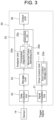
- FIG. 3 is a functional block diagram illustrating a functional configuration of the state monitoring device 20.
- the state monitoring device 20 includes a signal acquisition unit 21, a drive control unit 22, a data collection unit 23, a storage unit 24, an analysis unit 25, and an output unit 26.
- the functions of the respective units illustrated in FIG. 3 are realized by the CPU 20a ( FIG. 1 ) when the CPU 20a executes relevant programs.
- the signal acquisition unit 21 obtains a trigger signal from the equipment having the ball screw.
- the trigger signal is generated from the equipment when the workpiece W is not processed, e.g., before the workpiece W is processed or after the workpiece W is processed.
- the drive control unit 22 controls the servo motor 11 ( FIG. 1 ) as the trigger signal is acquired by the signal acquisition unit 21, and the drive control unit 22 actuates the ball screw 10 in a diagnosis mode.
- the ball screw 10 is operated at a constant speed for one or more reciprocating motions (moving back and forth at least one time along a forward path and a return path) under a no-load condition (idling condition).
- the idling condition means that the screw shaft 1 and the nut 2 are moved relative to each other under an unloaded condition in which the workpiece W is not processed.
- the drive control unit 22 causes the nut 2 to move back and forth relative to the screw shaft 1 at a constant speed for one or more times (one or more reciprocating motions) under the unloaded condition.
- the unloaded condition refers to a condition or state in which the workpiece is not processed in the processing apparatus, and the ball screw 10 is not subjected to any load generated by the processing of the workpiece. That is, the unloaded condition (unloaded state) does not mean a state in which there is no load acting on the ball screw 10 due to the device configuration or the product specification, such as a preload or a load derived from the weight of the table 12.
- the moving path of the nut 2 may include a path where the nut 2 moves under the loaded condition during the operation of the equipment having the ball screw 10, i.e., the path where the nut 2 moves during the processing of the workpiece W in the processing apparatus (processing path A in FIG. 1 ).
- An amount of data collected increases as the moving path of the nut 2 is longer.
- a noise component can be more reduced by averaging if an amount of data is large.
- it is desirable that the traveling distance (moving path) of the nut 2 is longer. The longer the traveling distance, the higer the accuracy of the state monitoring.
- the drive control unit 22 causes the ball screw 10 to move under the above-described unloaded condition (idling condition), and then ends the diagnosis mode.
- the data collection unit 23 starts collection of the vibration data detected by the vibration sensor 14 as the trigger signal is acquired by the signal acquisition unit 21. That is, the data collection unit 23 collects the vibration data in synchronization with the idling operation of the ball screw 10.
- the data collection unit 23 stops the data collection of the vibration data.
- the storage unit 24 stores the vibration data collected by the data collection unit 23 in a predetermined storage area.
- the state monitoring device 20 periodically drives the ball screw 10 in the diagnosis mode to collect vibration data.
- Conditions for collecting the vibration data are the same each time.
- the drive control unit 22 includes a drive condition storage unit 22a that stores conditions such as the operation pattern, and the drive control unit 22 controls the servo motor 11 based on the conditions stored in the drive condition storage unit 22a.
- the analysis unit 25 analyzes the vibration data, which is collected while driving (actuating) the ball screw 10 in the diagnostic mode, and monitors the state of the ball screw 10.
- the output unit 26 sends the state (status) information of the ball screw 10, which is the diagnosis result generated by the analysis unit 25, to the display unit 20d shown in FIG. 1 , and presents the diagnosis result to the user.
- the analysis unit 25 calculates a feature value (characteristic value) based on the collected vibration data, and compares the calculated characteristic value with a reference value to diagnose a state (presence or absence of occurrence of abnormality, etc.) of the ball screw 10.
- the characteristic value may include at least one of a RMS (root mean square) value, an overall value (OA value), a partial overall value (POA value), a crest factor (CF), and a kurtosis. It should be noted that the characteristic value is not limited to the above-mentioned values, and may be appropriately selected under given circumstances. If a threshold value to the characteristic value is set as the reference value in advance, the abnormality can be easily and appropriately determined by comparing the characteristic value with the threshold value.
- the analysis unit 25 may divide the vibration data into a plurality of portions, i.e., vibration data of a forward movement (forward path) portion, vibration data of a return movement (return path) portion, vibration data of processing (machining) in the forward and return movement portions, and vibration data of no-processing in the forward and return movement portions. Then, the analysis unit 25 may compare the analysis results (for example, the above-described characteristic values) of the respective vibration data with each other.
- the analysis unit 25 may include a comparative diagnostic unit 25a, an abnormal portion (location) specifying unit 25b, and a determination unit 25c.
- the comparative diagnostic unit 25a may compare the analysis results of the divided vibration data
- the determination unit 25c may determine the status of the ball screw 10 based on the comparison results generated by the comparative diagnostic unit 25a.
- Vibrations occur in the ball screw 10 as the balls 3 roll in the rolling path. Vibrations also occur in the ball screw 10 as the balls 3 enter and exit the loaded area and the unloaded area of the circulation path, and the like.
- a position at which each of the balls 3 transitions from the loaded area to the unloaded area and a position at which each of the balls 3 transitions from the unloaded area to the loaded area are reversed as a moving direction of the nut 2 reverses.
- the start position of the vibration is different between the forward path and the return path of the nut 2. Therefore, the same vibration data is not measured in the forward path and the return path.
- the comparative diagnostic unit 25a shown in FIG. 3 compares the characteristic value of the forward path with the characteristic value of the return path, it is possible to carry out the state monitoring using the change in the vibration data between the forward path and the return path, and it is possible to perform highly accurate state monitoring in which erroneous diagnosis due to a measurement error or the like is suppressed or eliminated.
- the comparative diagnostic unit 25a illustrated in FIG. 3 may compare the characteristic value of the processing area with the characteristic value outside the processing area.
- the analysis unit 25 may divide the vibration data of the entire area into data of a plurality of small areas, and compare the analysis results (e.g., characteristic values) of the divided vibration data. This makes it possible to identify a location at which the state of the ball screw changes. For example, if there is a flaw at a certain position on the rolling surface of the screw shaft 1, the characteristic value changes when the nut 2 moves over the flaw.
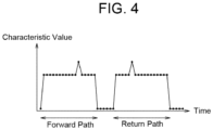
- FIG. 4 is an example of a characteristic value when there is a flaw at one position on the rolling surface of the screw shaft 1.
- FIG. 4 shows characteristic values for one reciprocal motion (forward path and return path).
- Each dot in FIG. 4 represents a characteristic value calculated from vibration data of each area.
- the portion where the characteristic value greatly fluctuates in each of the forward path and the return path. Therefore, by specifying the portion where the characteristic value changes, it is possible to specify the position where the flaw of the screw shaft 1 is generated (abnormality occurrence portion).
- the abnormal portion (location) specifying unit 25b illustrated in FIG. 3 may divide the vibration data of the entire area into a plurality of data as described above, and specify the abnormal portion of the ball screw 10 based on the analysis results of the divided data.
- the diagnostic accuracy can be improved by comparing the vibration data of the forward path with the vibration data of the return path.
- the comparative diagnostic unit 25a shown in FIG. 3 may compare the vibration data of the forward path with the vibration data of the return path, and the determination unit 25c may determine, based on the result of comparing the vibration data of the forward path with the vibration data of the return path by the comparative diagnostic unit 25a and the abnormality occurrence location identified by the abnormality portion specifying unit 25b, whether the peak of the detected characteristic value is caused by the error of the measurement or caused by the abnormality that actually occurred on the screw shaft 1.
- the analysis unit 25 may diagnose the state of the ball screw 10 by arranging the characteristic values calculated from the above-mentioned plural vibration data (i.e., the vibration data of the forward path, the vibration data of the return path, the vibration data of the processing area, and the vibration data of the no-processing area) in time series and monitoring the change in the tendency of the characteristic values. With this diagnosis, the state of the ball screw 10 can be diagnosed with higher accuracy.
- the characteristic values calculated from the above-mentioned plural vibration data i.e., the vibration data of the forward path, the vibration data of the return path, the vibration data of the processing area, and the vibration data of the no-processing area
- the analysis unit 25 may arrange the characteristic values calculated from the vibration data in time series, without dividing the vibration data into the forward path, the return path, the processing area, and the no-processing area, and monitor the change in the tendency of the characteristic values. Although the accuracy of the state monitoring of this diagnosis is inferior, the calculation can be simplified, and the memory required for the analysis can be reduced.
- the state monitoring device 20 includes the respective units illustrated in FIG. 3 , but for example, at least one of the storage unit 24, the analysis unit 25, and the output unit 26 may be provided in a separate device other than state monitoring device 20.
- the state monitoring device 20 may transmit the data collected by the data collection unit 23 to the separate device other than the state monitoring device 20 such that the separate device may analyze the data to diagnose the state of the ball screw 10.
- the state monitoring device 20 of this embodiment controls the servo motor 11 to cause the nut 2 to move relative to the screw shaft 1 at a constant speed for one or more reciprocating motions under the unloaded condition, thereby actuating the ball screw 10 in the diagnostic mode. In the meantime, the state monitoring device 20 collects the vibration data which will be used to monitor the state of the ball screw 10.
- the state monitoring device 20 can actuate the ball screw 10 in the diagnostic mode in the above-described manner, it is possible for the state monitoring device 20 to perform data collection appropriately even if the equipment to be monitored does not have an idling operation at a constant speed for one or more reciprocating motions during a series of operation cycles. Further, since the state monitoring device 20 collects the vibration data during the idling operation time, not during the processing time, it is possible for the state monitoring device 20 to collect the vibration data while minimizing influence of disturbance generated during the processing. Further, since the idling operation is carried out one or more reciprocations, it is possible to improve the accuracy of the state monitoring. In addition, since the idling operation is performed at a constant speed, stable data measurement can be performed.
- the idling movement section may include a section (area) in which the nut 2 of the ball screw 10 will move while processing is performed. This makes it possible to include, in the collected vibration data, a signal (data) when the nut moves over an area or portion where an abnormality is likely to occur. Therefore, for example, by comparing the characteristic value calculated from the vibration data of the processing area with the characteristic value calculated from the vibration data outside the processing area, it is possible to find the deterioration and damage in the processing area. In this way, abnormality detection can be appropriately performed.
- the nut moving area and the nut moving distance of the idling operation can be decided based on predetermined parameters, such as the processing area A as well as the operation cycle of the ball screw 10 and the type of the ball screw 10.
- this embodiment uses the values measured during the idling operation at the constant speed for one or more reciprocating motions to detect the damage of the screw shaft 1, the damage of the nut 2 and the like, which has the dependency of the position. Thus, it is possible to accurately detect which part of the ball screw 10 is damaged. This contributes to systematic preventive maintenance.
- the above-described first embodiment deals with a configuration in which the state of the ball screw 10 is diagnosed by using the measured values obtained when the screw shaft 1 and the nut 2 are moved relative to each other at a constant speed under the unloaded condition for one or more reciprocating motions.
- the state of the ball screw 10 is diagnosed by using values measured while the screw shaft 1 and the nut 2 are moved relative to each other at a constant speed in one direction under the unloaded condition within a predetermined operation cycle or operation pattern.
- FIG. 5 is a diagram illustrating a schematic configuration of a system that includes a state monitoring device 20A of the second embodiment.
- the hardware configuration of the state monitoring device 20A is the same as the hardware configuration of the state monitoring device 20 shown in FIG. 1 .
- FIG. 6 is a diagram illustrating a functional configuration of the state monitoring device 20A of the second embodiment.
- the state monitoring device 20A includes a signal acquisition unit 21, a data collection unit 23, a storage unit 24, an analysis unit 25, and an output unit 26.
- the functions of the respective units illustrated in FIG. 6 are realized by CPU 20a illustrated in FIG. 5 as the CPU 20a executes predetermined programs. Some functions of the units illustrated in FIG. 6 are different from the functions of the units of the state monitoring device 20 illustrated in FIG. 3 .
- the signal acquisition unit 21 obtains a trigger signal from the equipment having the ball screw.
- the trigger signal is a signal indicating a period during which the nut 2 moves relative to the screw shaft 1 at a constant speed in one direction under the unloaded condition within the operation cycle or the operation pattern of the ball screw 10.
- the unloaded condition refers to a state in which the workpiece is not processed in the processing apparatus, and the ball screw 10 is not subjected to any load generated by the processing of the workpiece. That is, the unloaded condition does not mean a state in which there is no load acting on the ball screw 10 due to the device configuration and the product specification, e.g., a preload may be applied under the unloaded condition and a load due to the weight of the table 12 may be applied under the unloaded condition.
- the ball screw 10 performs an operation of returning to the origin position (zero return) upon, for example, starting of the equipment, replacement of the tool 30, replacement of the workpiece W, and the like. Therefore, the signal acquisition unit 21 may obtain, for example, a trigger signal that indicates a period during which the ball screw 10 returns to the origin.
- the ball screw 10 may have a grease supply cycle. During the grease supply cycle, lubricant (grease, oil) is supplied to the ball screw 10, and then the ball screw 10 is caused to travel at a constant speed for a predetermined distance in order to stir the lubricant within the ball screw. Therefore, the signal acquisition unit 21 may obtain, for example, a trigger signal indicating that the ball screw is in the grease supply cycle.
- lubricant grey, oil
- the signal acquisition unit 21 may use (decide) a predetermined period from the timing of receiving the trigger signal, as a period in which the nut 2 moves relative to the screw shaft 1 in one direction at a constant speed under the unloaded condition within the operation cycle or the operation pattern of the ball screw 10, i.e., as a data collection period.
- the signal acquisition unit 21 may obtain the data collection period in this manner.
- the signal acquisition unit 21 may obtain the data collection period by receiving a trigger signal indicating the start of the data collection period and another trigger signal indicating the end of the data collection period.
- the signal acquisition unit 21 corresponds to a period acquisition unit.
- the signal acquisition unit 21 acquires, as the data collection period, a period in which the nut 2 moves in one direction, rather than two directions (the forward direction and the return direction). Therefore, data collection can be performed in a relatively short time. From the viewpoint of SN ratio, it is desirable that the data collection period is a period in which the rotational speed of the screw shaft 1 is equal to or higher than 100 rpm.
- the moving area of the nut 2 along the screw shaft when the nut 2 moves during the data collection period may include an area in which the nut 2 moves under a loaded condition during operation of the equipment having the ball screw 10, i.e., an area in which the nut 2 moves during processing of the workpiece W in the processing apparatus (processing area A in FIG. 5 ).
- An amount of data collected increases as the moving area (moving distance) of the nut 2 increases, and the noise component can be reduced by averaging.
- it is desirable that the moving distance (traveling distance) is longer. The longer the moving distance, the better the accuracy of the state monitoring.
- the signal acquisition unit 21 acquires the data collection period based on the trigger signal, but the method of acquiring the data collection period is not limited thereto.
- the signal acquisition unit 21 may acquire the operation cycle information of the ball screw 10 and determine the data collection period based on the acquired information.
- the data collection unit 23 collects the vibration data, which is supplied from the vibration sensor 14, in the data collection period defined or obtained by the signal acquisition unit 21. Specifically, the data collection unit 23 collects the vibration data in synchronization with the operation cycle (processing cycle) of the ball screw 10 in production time.
- the storage unit 24 stores the vibration data, which is collected by the data collection unit 23, in a predetermined storage area.
- the state monitoring device 20A periodically collects vibration data.
- Conditions for collecting vibration data (operation pattern, moving direction of the nut 2, sampling time, data collection time, and the like) are the same each time.
- vibrations are caused by, for example, the balls 3 rolling along the rolling path, and another vibrations are caused by the balls 3 entering and exiting the loaded area and the unloaded area of the circulation path.
- a position at which the ball transitions from the loaded area to the unloaded area and a position at which the ball transitions from the unloaded area to the loaded area are reversed according to a moving direction of the nut 2. That is, the vibration starting positions are different between the forward path and the return path. Therefore, the same vibration data is not measured in the forward path and the return path. Thus, when the vibration data is collected periodically, the vibration data is collected under the condition that the moving direction of the nut 2 is always the same.
- the stability of the data is taken into consideration, it is desirable to collect the data in a warm state of the equipment (after the warming-up period of the equipment). In order to appropriately grasp the occurrence of an abnormality, it is desirable that the data collection is carried out two times or more a day (operation day).
- the arrow indicating the moving direction of the nut 2 shows the right direction, but the moving direction of the nut 2 during the data collection period may be the left direction.
- the analysis unit 25 analyzes the vibration data, which is stored in the storage unit 24, and monitors the state of the ball screw 10.
- the output unit 26 outputs (displays) the state of the ball screw 10, which is the diagnosis result of the analysis unit 25, on the display unit 20d shown in FIG. 5 to present the diagnosis result to the user.
- the analysis unit 25 calculates a characteristic value based on the collected vibration data, and compares the calculated characteristic value with a reference value to diagnose a state of the ball screw 10 (presence or absence of abnormality, etc.).
- the characteristic value may include at least one of a RMS value, an overall value (OA value), a partial overall value (POA value), a crest factor (CF), and a kurtosis. It should be noted that the characteristic value is not limited to the above-mentioned values, and can be appropriately selected. If a threshold value of the characteristic value is set to the reference value in advance, the abnormality can be easily and appropriately detected by comparing the characteristic value with the threshold value.
- the analysis unit 25 may divide the vibration data into two groups, i.e., vibration data of the processing area and vibration data of the no-processing area, and compare analysis results (for example, the above-described characteristic values) of the respective vibration data.
- the analysis unit 25 may include a comparative diagnostic unit 25a, an abnormal portion (location) specifying unit 25b, and a determination unit 25c.
- the comparative diagnostic unit 25a may compare the analysis results of the divided vibration data
- the determination unit 25c may determine the state of the ball screw 10 based on the comparison results prepared by the comparative diagnostic unit 25a.
- the comparative diagnostic unit 25a illustrated in FIG. 6 may compare the characteristic values of the processing area with the characteristic values outside the processing area.
- the analysis unit 25 may divide the vibration data of the entire area into data of a plurality of small areas, and compare the analysis results (e.g., characteristic values) of the divided vibration data with each other. This makes it possible to identify a position at which the state of the ball screw changes. For example, if there is a flaw in one area on the rolling surface of the screw shaft 1, the characteristic value changes only when the nut 2 moves over the flaw.
- FIG. 7 illustrates an example of characteristic values when a flaw exists at one position on the rolling surface (surface on which the balls roll) of the screw shaft 1.
- Each dot in FIG. 7 represents a characteristic value calculated from the vibration data of each small area which is defined by dividing the entire moving path of the nut.
- a portion (peak) where the characteristic value greatly fluctuates can be detected. Therefore, by specifying the portion (peak) where the characteristic value changes, it is possible to determine the position where the flaw of the screw shaft 1 exists (abnormality occurrence location).
- the abnormal portion specifying unit 25b illustrated in FIG. 6 may divide the vibration data of the entire area into a plurality of data as described above, and specify the abnormal portion of the ball screw 10 (location of occurrence of the abnormal state) based on the analysis results of the divided data.
- the analysis unit 25 may be configured to diagnose the state of the ball screw 10 by arranging the characteristic values calculated from the divided vibration data, i.e., the vibration data of the processing area and the vibration data of the no-processing area, in time series and monitoring the change in the tendency of the characteristic values. This analysis unit can diagnose the state of the ball screw 10 with higher accuracy.
- the analysis unit 25 may arrange in time series the characteristic values calculated without dividing the vibration data into the processing area and the no-processing area, and monitor the change in the tendency of the characteristic values.
- this analysis unit cannot carry out a simple diagnosis, which uses comparison between the characteristic values of the processing area and the characteristic values of the no-processing area, the calculation can be simplified, and the memory required for the analysis can be reduced.
- the state monitoring device 20A of this embodiment includes the respective units illustrated in FIG. 6 , but, for example, at least one of the storage unit 24, the analysis unit 25, and the output unit 26 may be included in a separate device other than the state monitoring device 20A.
- the state monitoring device 20A may transmit the data, which is collected by the data collection unit 23, to the separate device other than the state monitoring device 20A, and the separate device may analyze the data to diagnose the state of the ball screw 10.
- the state monitoring device 20A of this embodiment obtains, as the data collection period, a period in which the nut 2 moves relative to the screw shaft 1 at a constant speed in one direction under the no-load condition within the operation cycle or the operation pattern of the ball screw 10. Then, the state monitoring device collects vibration data of the data collection period as data for monitoring the state of the ball screw 10.
- the state monitoring device 20A collects the vibration data during the unloaded time, rather than collecting the vibration data during processing. Therefore, it is possible to collect vibration data that minimizes the influence of disturbance generated during processing. Further, since the vibration data is collected during the operation cycle or the operation pattern of the ball screw 10, it is not necessary to intervene the diagnostic mode (i.e., it is not necessary to additionally carry out the diagnostic mode) for data collection. Therefore, it is possible to prevent a decrease in productivity. In addition, since the data collection area is not reciprocating areas, but a one-way area in which the nut 2 is moved in one direction (forward direction or return direction), the measurement time can be shortened. Furthermore, since vibration data is collected during the period in which the nut 2 is moving at a constant speed, stable data measurement can be performed.
- the nut moving area in which the nut 2 moves during the data collection period may include an area in which the nut 2 of the ball screw 10 moves when processing is performed. This makes it possible to include, in the collected vibration data, a signal generated when the nut moves over a portion (position) where an abnormality is likely to occur. Therefore, for example, by comparing the characteristic value calculated from the vibration data of the processing area with the characteristic value calculated from the vibration data outside the processing area, it is possible to grasp the deterioration and damage in the processing area. In this way, abnormality detection can be appropriately performed.
- the moving area and the moving distance of the nut 2 in the data collection period can be set based on predetermined parameters such as the processing area A as well as the operation cycle of the ball screw 10 and the type of the ball screw 10.
- the vibration data is periodically (repeatedly) collected under the same conditions.
- the collected vibration data can be arranged in time series and the tendency of the vibration data can be monitored. Therefore, when the state of the ball screw changes due to occurrence of an abnormality or the like, it is possible to appropriately detect the change of the state of the ball screw. Since the vibration data of the nut 2 that moves in the same direction is collected each time, the diagnostic accuracy can be improved.
- the measurement values under the unloaded condition during a manufacturing process are used.
- the equipment whose tact time is short and which is operated 24 hours it is possible to collect data during a series of operation cycles without stopping the manufacturing process.
- the state of the ball screw 10 can be monitored in line without adversely affecting the tact time of the manufacturing process. Accordingly, preventive maintenance can be carried out according to a planned schedule.
- the position at which the vibration sensor 14 is fixed is not limited to the nut.
- the vibration sensor 14 may be fixed to a moving member that is movable relative to the screw shaft 1 together with the nut 2 in the vicinity of the nut 2 or in an area close to the nut 2 as much as possible. Examples of such moving member include the table 12 and the bracket 13 illustrated in FIG. 1 .
- the vibration detected by the vibration sensor 14 may be vibration in the axial direction or vibration in the circumferential direction, but the vibration in the axial direction is more desirable.
- the physical quantity related to the ball screw may be the torque or the current of the servo motor 11.
- the wiring used to dispose the sensor for detecting the physical quantity related to the ball screw 10 becomes easier/simpler than the configuration of detecting the vibration data.
- the vibration data directly represents (indicates) the physical information of the monitoring target
- the torque information and the electric current data include a considerable amount of information on other elements such as a bearing and a guide mechanism.
- the diagnostic accuracy tends to be slightly lower when the torque and/or the electric current is used than when the vibration data is used.
- each of the above-described embodiments deals with the configuration in which the characteristic value is calculated based on the collected vibration data, and the characteristic value is compared with the reference value to determine the state of the ball screw, the characteristic value may not be calculated, i.e., the waveform of the vibration data may be directly compared with a reference waveform to determine the state of the ball screw.
- the equipment having the ball screw 10 may be a conveyance apparatus, an injection molding machine, or other production equipment. Even if the equipment having the ball screw is the conveyance apparatus or the like, it is still possible to appropriately collect data for diagnosing the state of the ball screw 10 with higher accuracy, as in the above-described embodiments.
- the present invention may be realized by supplying a program, which is designed to realize one or more functions of the above-described embodiments, to a system or an apparatus via a network or a storage medium, and reading and executing the program by one or more processors in a computer of the system or the apparatus.
- the program itself, which is read from the recording medium, realizes the functions of the embodiment(s).
- the recording medium on which the program is recorded can constitute the present invention.
- the way of realizing the functions of the embodiments is not limited to causing the computer to read and execute the program so as to realize the functions of the embodiments.
- the functions of the above-described embodiments may be realized by the operating system (OS) or the like running on the computer and performing some or all of the processing based on the instructions of the program.
- OS operating system
Landscapes
- Engineering & Computer Science (AREA)
- General Engineering & Computer Science (AREA)
- Physics & Mathematics (AREA)
- General Physics & Mathematics (AREA)
- Mechanical Engineering (AREA)
- Acoustics & Sound (AREA)
- Transmission Devices (AREA)
- Testing Of Devices, Machine Parts, Or Other Structures Thereof (AREA)
Abstract
Description
- The present invention relates to a state monitoring device and a state monitoring method for a ball screw.
- A ball screw, which has a screw shaft, a nut, and a plurality of balls such that the nut and the screw shaft move relative to each other via the balls, is known as a rolling linear motion device. Methods of monitoring the state of the ball screw are disclosed in, for example,
Patent Literature Documents -
Patent Literature Document 1 discloses a technique in which a data collection period T for capturing output signals of the sensor is set to be equal to or more than a period t in which the balls that move back and forth in an infinite circulation path enters a loaded passage from an unloaded passage, and state monitoring (status monitoring) is performed in consideration of vibration generated when the balls enter and exit the loaded passage. -
Patent Literature Document 2 discloses a technique in which a trigger signal for obtaining a measurement timing is generated (prepared) from an acceleration signal acquired from the vibration acceleration sensor, and vibration measurement data is extracted only during steady speed operation to perform state monitoring. -
- Patent Literature Document 1:
Japanese Patent No. 6403743 - Patent Literature Document 2:
Japanese Patent Application Laid-Open Publication No. 2012-98213 JP-A-2012-98213 - However, in the technique described in each of the above-mentioned Patent Literature Documents, the state monitoring is carried out by extracting a part of vibration data obtained when the nut of the ball screw that can reciprocate along a forward path and a return path moves in one of the two directions (the forward path direction or the return path direction). Therefore, there is a possibility that abnormality of a component of the ball screw, which clearly becomes detectable when the nut reaches a particular position, cannot be accurately detected.
- The ball screw is used in various production equipment/machines such as a machine tool, a conveying device, and an injection molding machine, and it is desirable that the state monitoring of the ball screw is performed in-line so as not to affect the tact time of production (manufacturing) in the production equipment. However, the technology described in each of the above-mentioned Patent Literature Documents does not consider this point.
- Therefore, an object of the present invention is to provide a state monitoring (status monitoring) device and a state monitoring method for a ball screw capable of appropriately collecting data for diagnosing a state of the ball screw with higher accuracy.
- Another object of the present invention is to provide a state monitoring device and a state monitoring method for a ball screw capable of collecting data for diagnosing a state of a ball screw in-line without affecting a tact time in production.
- In order to solve the above-mentioned problems, a device for monitoring a state of a ball screw according to one aspect of the present invention is directed to a state monitoring device to monitor the state of the ball screw having a screw shaft, a nut, and a plurality of balls. The state monitoring device for the ball screw includes a drive control unit configured to control a drive unit that causes the nut to move relative to the screw shaft at a constant speed under an unloaded condition for at least one reciprocating motion along a forward path and a return path. The state monitoring device for the ball screw also includes a data collection unit that collects, as data, a physical quantity related to the ball screw while the drive unit is being controlled by the drive control unit.
- The unloaded condition refers to a condition or state in which the equipment having the ball screw does not perform processing on a workpiece and the ball screw is not subjected to any load caused by the workpiece processing. For example, if a processing apparatus such as a machine tool has a ball screw, the unloaded condition refers to a state in which a workpiece is not processed in the processing apparatus, and the ball screw is not subjected to any load generated upon processing of the workpiece. In other words, the unloaded condition is not a condition in which there is no load acting on the ball screw according to a device configuration or a product specification, i.e., a preload or a load due to the weight of a machining table may act on the ball screw under the "unloaded condition."
- Since the ball screw is operated at a constant speed for one or more reciprocating motions under the unloaded condition (idling condition) and the data is collected while the ball screw is being operated, it is possible to collect diagnostic data that contribute to more accurate detection of abnormality of the components of the ball screw (e.g., damage to the screw shaft and damage to the nut), which has nut position dependency.
- In the state monitoring device for the ball screw, the drive control unit may control the drive unit such that the reciprocating motion of the nut includes a nut moving section in which the nut would be caused to move under a loaded condition if an equipment having the ball screw is operated.
- For example, if a processing apparatus such as a machine tool has a ball screw, abnormalities such as component damage are likely to occur in a section where a nut travels during processing. Since a section where the nut travels at the time of processing is included in the reciprocating path of the nut to which data collection is performed, abnormality detection can be appropriately performed.
- In the state monitoring device for the ball screw, the drive control unit may include a drive condition storage unit that stores a drive condition for controlling the drive unit periodically under a same condition.
- With this configuration, the collected data can be arranged in time series, and the trend of the collected data can be monitored. Therefore, when the state of the ball screw changes due to occurrence of an abnormality or the like, it is possible to appropriately detect the change in the state of the ball screw. In addition, since the data is collected under the same condition each time, the diagnostic accuracy can be improved.
- The state monitoring device for the ball screw may further include an analysis unit that analyzes data collected by the data collection unit and monitors the state of the ball screw.
- With this configuration, the collected data can be used to accurately detect abnormality of the components of the ball screw (e.g., damage to the screw shaft and damage to the nut) because the location of abnormality is dependent from the position of the nut. Thus, it is possible to carry out systematic preventive maintenance.
- In the state monitoring device for the ball screw, the analysis unit may have a comparative diagnosis unit that compares an analysis result of data of the forward path with an analysis result of data of the return path among the data collected by the data collection unit, and diagnoses the state of the ball screw.
- With this configuration, the diagnosis of the ball screw can appropriately be performed by utilizing the change in data between the forward path and the return path of the ball screw. Thus, it is possible to perform highly accurate state monitoring in which erroneous diagnosis due to measurement error or the like is suppressed or eliminated.
- In the state monitoring device for the ball screw, the analysis unit may have an abnormal portion specifying unit that divides the data, which is collected by the data collection unit, into a plurality of data, and specifies a location of occurrence of abnormality in the ball screw based on an analysis result of the divided data.
- With this configuration, it is possible to specify where the abnormality occurs in the ball screw. Upon knowing the location of the abnormality, it is possible to promptly perform maintenance or the like of the ball screw.
- In order to solve the above-mentioned problems, there is provided another device for monitoring a state of a ball screw according to another aspect of the present invention, which is directed to a state monitoring device for the ball screw having a screw shaft, a nut, and a plurality of balls. The state monitoring device includes a period acquisition unit configured to acquire, as a data collection period, a period in which the nut is caused to move relative to the screw shaft at a constant speed in one direction under an unloaded condition within a predetermined operation cycle or a predetermined operation pattern of the ball screw. The state monitoring device also includes a data collection unit that collects, as data, a physical quantity related to the ball screw in the data collection period acquired by the period acquisition unit.
- The unloaded condition refers to a condition or state in which the equipment provided with the ball screw does not perform any processing (machining) on a workpiece and the ball screw is not subjected to a load generated by the processing (machining). For example, if a processing apparatus such as a machine tool is provided with the ball screw, the unloaded condition means a state in which a workpiece is not processed in the processing apparatus, and the ball screw is not subjected to any load generated by the processing applied to the workpiece. In other words, the unloaded condition does not refer to a state in which there is no load acting on the ball screw due to a device configuration and/or a product specification, e.g., a preload may act on the ball screw under the unloaded condition, and a load due to the weight of a table of the machine tool may act on the ball screw under the unloaded condition.
- As described above, in the operation cycle and operation pattern of the ball screw, the period during which the nut is moving at the constant speed in the particular direction under the unloaded condition is defined as the data collection period. Since the data is collected during this data collection period, it is possible to collect data, which will be used to diagnose the state of the ball screw, in-line (during the manufacturing process) without affecting the tact time of manufacturing.
- In the state monitoring device for the ball screw, the period acquisition unit may acquire, as the data collection period, a period in which the ball screw makes a zero return movement (the ball screw returns to an original or start position). With this configuration, it is possible to collect data when the nut moves back to the predetermined position, e.g., when the nut moves back to the predetermined position upon starting up of the equipment having the ball screw, when the nut moves back to the predetermined position upon replacement of the tool, or when the nut moves back to the predetermined position upon replacement of the workpiece.
- In the state monitoring device for the ball screw, the period acquisition unit may acquire, as the data collection period, a grease supply cycle of the ball screw. With this configuration, for example, after the lubricant (grease, oil) is replenished, it is possible to collect data when the nut travels at a constant speed for a predetermined distance in order to agitate the lubricant.
- In the state monitoring device for the ball screw, the period acquisition unit may acquire the data collection period such that a moving area of the nut during the data collection period includes an area in which the nut is caused to move under a loaded condition during operation of an equipment having the ball screw.
- For example, if a processing apparatus such as a machine tool has the ball screw, abnormalities such as component damage are likely to occur in a section where the nut moves during processing. Because the data collection period includes a section where the nut moves at the time of processing, abnormality detection can be appropriately performed.
- In the state monitoring device for the ball screw, the period acquisition unit may periodically acquire the data collection period under a same condition.
- With this configuration, the collected data can be arranged in time series, and the trend (change) of the data can be monitored. Therefore, when the state of the ball screw changes due to occurrence of an abnormality or the like, it is possible to appropriately detect the change. In addition, in consideration of the fact that the physical quantity (for example, vibration) related to the ball screw is different between the forward path and the return path, the data is collected when the nut is moving in the same direction each time. Thus, it is possible to improve the accuracy of the diagnosis.
- The state monitoring device for the ball screw may further include an analysis unit that analyzes data collected by the data collection unit and monitors the state of the ball screw.
- With this configuration, the state of the ball screw can be appropriately monitored by using the data collected in-line.
- In the state monitoring device for the ball screw, the analysis unit may include an abnormal portion specifying unit that divides the data, which is collected by the data collection unit, into a plurality of data, and specifies a location of occurrence of abnormality in the ball screw based on an analysis result of the divided data.
- With this configuration, it is possible to specify where the abnormality occurs in the ball screw. Thus, it is possible to promptly perform maintenance or the like of the ball screw.
- In the state monitoring device for the ball screw, the physical quantity may be the vibration of the nut in the axial direction of the ball screw. With this configuration, the vibration generated in the nut can be appropriately detected.
- The state monitoring device for the ball screw may further include a vibration sensor configured to detect vibration and provide vibration data. The vibration sensor may be fixed to the nut or may be fixed to a movable member that is operatively coupled to the nut and is movable relative to the screw shaft together with the nut. With this configuration, the vibration sensor can directly collect the physical information of the monitoring target. Thus, highly accurate state monitoring becomes possible.
- In the state monitoring device for the ball screw, the drive unit may be a servo motor for driving the ball screw, and the physical quantity may be at least one of a torque and an electric current of the servo motor.
- With this configuration, the torque and the electric current of the servo motor need only be detected. Thus, a complicated wiring for installing a sensor adapted to detect the physical quantity related to the ball screw is not required.
- A method of monitoring a state of a ball screw according to still another aspect of the present invention is directed to a state monitoring method for monitoring the state of a ball screw having a screw shaft, a nut, and a plurality of balls. The method includes a step of controlling a drive unit that causes the nut to move relative to the screw shaft at a constant speed under an unloaded condition for at least one reciprocating motion along a forward path and a return path. The method also includes a step of collecting, as data, a physical quantity related to the ball screw while the drive unit is being controlled.
- As described above, since the ball screw is operated at the constant speed under the unloaded condition for one or more reciprocating motions and the data is collected while the ball screw is being operated, it is possible to collect diagnostic data that contribute to more accurate detection of abnormality (e.g., damage to the screw shaft and damage to the nut) of the components of the ball screw, which has location dependency.
- Another method of monitoring a state of a ball screw according to yet another aspect of the present invention is directed to another state monitoring method for monitoring the state of a ball screw having a screw shaft, a nut, and a plurality of balls. The method includes a step of acquiring, as a data collection period, a period in which the nut is caused to move relative to the screw shaft at a constant speed in one direction under an unloaded condition within a predetermined operation cycle of the ball screw or a predetermined operation pattern of the ball screw. The method also includes a step of collecting, as data, a physical quantity related to the ball screw in the data collection period.
- As described above, in the operation cycle and operation pattern of the ball screw, the period during which the nut is moving at the constant speed in the particular direction under the unloaded condition is defined as the data collection period and the data is collected during the data collection period, it is possible to collect data for diagnosing the state of the ball screw in-line without affecting the tact time of manufacturing.
- According to one embodiment of the present invention, since the ball screw is operated at a constant speed under an idling condition for one or more reciprocating motions (forward motion and return motion), it is possible to appropriately collect data for diagnosing the state of the ball screw with higher accuracy.
- According to another embodiment of the present invention, it is possible to collect data for diagnosing the state of the ball screw in-line without affecting the tact time in production.
-
-
FIG. 1 illustrates a schematic configuration of a system including a state monitoring device according to a first embodiment of the present invention. -
FIG. 2 illustrates an example of a ball screw. -
FIG. 3 is a functional block diagram of the state monitoring device according to the first embodiment. -
FIG. 4 is a diagram useful to describe a method of identifying a location of abnormality occurrence according to the first embodiment. -
FIG. 5 illustrates a schematic configuration of a system including a state monitoring device according to a second embodiment of the present invention. -
FIG. 6 is a functional block diagram of a state monitoring device according to the second embodiment. -
FIG. 7 is a diagram useful to describe a method of identifying a location of abnormality occurrence according to the second embodiment. - Hereinafter, embodiments of the present invention will be described with reference to the drawings.
- The scope of the present invention is not limited to the following embodiments, and can be arbitrarily changed within the scope of the technical concept of the present invention.
-
FIG. 1 illustrates a schematic configuration of a system including astate monitoring device 20 for monitoring a state of aball screw 10. - As shown in
FIG. 1 , theball screw 10 includes ascrew shaft 1 and anut 2. A rotary shaft of aservo motor 11 is connected to thescrew shaft 1 via a coupling. Theservo motor 11 is a drive unit that drives theball screw 10. When the rotation of theservo motor 11 is transmitted to thescrew shaft 1 to cause thescrew shaft 1 to rotate, thenut 2 is moved in the axial direction of thescrew shaft 1. -
FIG. 2 illustrates an example of theball screw 10. - The
screw shaft 1 of theball screw 10 is formed of an elongated cylindrical metallic member. As shown inFIG. 2 , a spiral rolling groove (spiral groove) 1a is formed on an outer surface of thescrew shaft 1. - The
nut 2 is formed of a substantially cylindrical metal member having a circular through-hole larger than an outer diameter of thescrew shaft 1. A spiral rolling groove (spiral groove) 2a is formed on the inner peripheral surface of thenut 2 so as to correspond to (engage with) thespiral groove 1a of thescrew shaft 1. Thespiral groove 1a of thescrew shaft 1 and thespiral groove 2a of thenut 2 form, in combination, a rolling path in whichballs 3 of the ball screw roll. - The
nut 2 has a straightball return path 2b extending axially therein. Theball return path 2b is used to return theballs 3 from the end point to the start point of the rolling path. - Small
fitting members 4 are embedded in opposite ends of thenut 2 in the axial direction. Each of thefitting members 4 is made of, for example, a resin member. A turningpath 4a is formed in each of thefitting members 4. The turningpath 4a communicates the rolling path to theball return path 2b, and has a substantially arc shape. It should be noted that the material of thefitting members 4 is not limited to resin, e.g., thefitting members 4 may be made of metal. - The rolling path, which is formed by the two grooves (i.e., the
spiral groove 1a of thescrew shaft 1 and thespiral groove 2a of the nut 2), theball return path 2b of thenut 2, and theturning paths 4a of the twofitting members 4 constitute, in combination, a circulation path through which theballs 3 circulate. A large number ofballs 4 are loaded in the circulation path such that thescrew shaft 1 and thenut 2 move relative to each other via theballs 3 rolling in the rolling path, which is a part of the circulation path. In the circulation path, therefore, the rolling path formed by thespiral groove 1a of thescrew shaft 1 and thespiral groove 2a of thenut 2 defines a loaded area in which theballs 3 may be subjected to an external load, whereas a combination of theball return path 2b of thenut 2 and theturning paths 4a of thefitting members 4 defines an unloaded area. - The
balls 3 are subjected to an external load applied to theball screw 10 in the rolling path and/or are subjected to a preload. Each of theballs 3 is made of a spherical metal member. It should be noted that the material of theballs 3 is not limited to metal, and may be ceramics or the like. Further, the rolling elements used in theball screw 10 are not limited to thespherical balls 3, and may be rollers (needle or cylindrical rollers). - Although the
ball screw 10 including thefitting members 4 has been described in the foregoing description as shown inFIG. 2 , the circulation member for circulating theballs 3 is not limited to the above-described configuration. For example, theball screw 10 may be a tube type or the like, i.e., the circulation type is not limited to a particular type. - In the following description of this embodiment, the
ball screw 10 is used in a processing apparatus such as a machine tool. - As shown in
FIG. 1 , a table 12 on which a workpiece (object to be processed) W is placed is connected to thenut 2 of theball screw 10 via abracket 13. The table 12 can reciprocate (move forward and return) along the axial direction of thescrew shaft 1 together with thenut 2. By moving the table 12, a desired portion (area) of the workpiece W can be processed by atool 30 such as a cutting tool. For example, the entire surface of the workpiece W may be processed by moving thenut 2 in the processing section A shown inFIG. 1 . - A
vibration sensor 14 is fixed to an end face (nut flange end face) of thenut 2 in the axial direction. Thevibration sensor 14 detects vibration in the traveling direction (axial direction) of thenut 2 as a physical quantity related to theball screw 10. The physical quantity of theball screw 10 detected by thevibration sensor 14 may be vibration in the circumferential direction of thenut 2. However, the axial vibration of the nut 2 (vibration in the axial direction of the ball screw) is more desirable as the physical quantity of theball screw 10. - The vibration data detected by the
vibration sensor 14 is sent to thestate monitoring device 20. - The
state monitoring device 20 can be constituted by, for example, a microcomputer. Thestate monitoring device 20 includes aCPU 20a, aROM 20b, aRAM 20c, and adisplay unit 20d. For example, theCPU 20a loads a necessary program and the like from theROM 20b into theRAM 20c, and executes the program and the like to realize various functional operations. Specifically, theCPU 20a realizes a monitoring function for monitoring the state or status of theball screw 10 based on vibration data obtained from thevibration sensor 14. Thedisplay unit 20d includes a display monitor such as a liquid crystal display. -
FIG. 3 is a functional block diagram illustrating a functional configuration of thestate monitoring device 20. - As illustrated in
FIG. 3 , thestate monitoring device 20 includes asignal acquisition unit 21, adrive control unit 22, adata collection unit 23, astorage unit 24, ananalysis unit 25, and anoutput unit 26. The functions of the respective units illustrated inFIG. 3 are realized by theCPU 20a (FIG. 1 ) when theCPU 20a executes relevant programs. - The
signal acquisition unit 21 obtains a trigger signal from the equipment having the ball screw. The trigger signal is generated from the equipment when the workpiece W is not processed, e.g., before the workpiece W is processed or after the workpiece W is processed. - The
drive control unit 22 controls the servo motor 11 (FIG. 1 ) as the trigger signal is acquired by thesignal acquisition unit 21, and thedrive control unit 22 actuates theball screw 10 in a diagnosis mode. In the diagnosis mode, theball screw 10 is operated at a constant speed for one or more reciprocating motions (moving back and forth at least one time along a forward path and a return path) under a no-load condition (idling condition). The idling condition means that thescrew shaft 1 and thenut 2 are moved relative to each other under an unloaded condition in which the workpiece W is not processed. In the diagnosis mode, therefore, thedrive control unit 22 causes thenut 2 to move back and forth relative to thescrew shaft 1 at a constant speed for one or more times (one or more reciprocating motions) under the unloaded condition. - The unloaded condition refers to a condition or state in which the workpiece is not processed in the processing apparatus, and the
ball screw 10 is not subjected to any load generated by the processing of the workpiece. That is, the unloaded condition (unloaded state) does not mean a state in which there is no load acting on theball screw 10 due to the device configuration or the product specification, such as a preload or a load derived from the weight of the table 12. - As the number of reciprocating motions (moving forward and returning) of the idle operation increases, an amount of data collected increases, and a noise component can be reduced by averaging, so that it is desirable that the number of reciprocating motions is larger. As the number of reciprocating motions increases, the accuracy of the state monitoring increases. In addition, from the viewpoint of SN (signal-noise) ratio, it is desirable that the rotational speed of the
screw shaft 1 be equal to or higher than 100 rpm. - As the conditions of the idling operation, the moving path of the
nut 2 may include a path where thenut 2 moves under the loaded condition during the operation of the equipment having theball screw 10, i.e., the path where thenut 2 moves during the processing of the workpiece W in the processing apparatus (processing path A inFIG. 1 ). An amount of data collected increases as the moving path of thenut 2 is longer. A noise component can be more reduced by averaging if an amount of data is large. Thus, it is desirable that the traveling distance (moving path) of thenut 2 is longer. The longer the traveling distance, the higer the accuracy of the state monitoring. - The
drive control unit 22 causes theball screw 10 to move under the above-described unloaded condition (idling condition), and then ends the diagnosis mode. - The
data collection unit 23 starts collection of the vibration data detected by thevibration sensor 14 as the trigger signal is acquired by thesignal acquisition unit 21. That is, thedata collection unit 23 collects the vibration data in synchronization with the idling operation of theball screw 10. - When the diagnosis mode is ended by the
drive control unit 22, thedata collection unit 23 stops the data collection of the vibration data. - The
storage unit 24 stores the vibration data collected by thedata collection unit 23 in a predetermined storage area. - In this embodiment, the
state monitoring device 20 periodically drives theball screw 10 in the diagnosis mode to collect vibration data. Conditions for collecting the vibration data (operation pattern, sampling time, data collection time, and the like) are the same each time. As illustrated inFIG. 3 , thedrive control unit 22 includes a drivecondition storage unit 22a that stores conditions such as the operation pattern, and thedrive control unit 22 controls theservo motor 11 based on the conditions stored in the drivecondition storage unit 22a. - When the stability/reliability of the data is taken into consideration, it is desirable to collect the data after the warming up of the
ball screw 10. Also, in order to appropriately detect the occurrence of an abnormality, it is desirable that the data collection is carried out one or more times a day (operation day). - The
analysis unit 25 analyzes the vibration data, which is collected while driving (actuating) theball screw 10 in the diagnostic mode, and monitors the state of theball screw 10. - The
output unit 26 sends the state (status) information of theball screw 10, which is the diagnosis result generated by theanalysis unit 25, to thedisplay unit 20d shown inFIG. 1 , and presents the diagnosis result to the user. - For example, the
analysis unit 25 calculates a feature value (characteristic value) based on the collected vibration data, and compares the calculated characteristic value with a reference value to diagnose a state (presence or absence of occurrence of abnormality, etc.) of theball screw 10. The characteristic value may include at least one of a RMS (root mean square) value, an overall value (OA value), a partial overall value (POA value), a crest factor (CF), and a kurtosis. It should be noted that the characteristic value is not limited to the above-mentioned values, and may be appropriately selected under given circumstances. If a threshold value to the characteristic value is set as the reference value in advance, the abnormality can be easily and appropriately determined by comparing the characteristic value with the threshold value. - In the analysis of the vibration data, the
analysis unit 25 may divide the vibration data into a plurality of portions, i.e., vibration data of a forward movement (forward path) portion, vibration data of a return movement (return path) portion, vibration data of processing (machining) in the forward and return movement portions, and vibration data of no-processing in the forward and return movement portions. Then, theanalysis unit 25 may compare the analysis results (for example, the above-described characteristic values) of the respective vibration data with each other. - For example, as illustrated in
FIG. 3 , theanalysis unit 25 may include a comparativediagnostic unit 25a, an abnormal portion (location) specifyingunit 25b, and adetermination unit 25c. In this configuration, the comparativediagnostic unit 25a may compare the analysis results of the divided vibration data, and thedetermination unit 25c may determine the status of theball screw 10 based on the comparison results generated by the comparativediagnostic unit 25a. - By comparing the characteristic value calculated from the vibration data of the forward path with the characteristic value calculated from the vibration data of the return path, it is possible to confirm variations (irregularities) in the vibration data.
- Vibrations occur in the
ball screw 10 as theballs 3 roll in the rolling path. Vibrations also occur in theball screw 10 as theballs 3 enter and exit the loaded area and the unloaded area of the circulation path, and the like. In theball screw 10, a position at which each of theballs 3 transitions from the loaded area to the unloaded area and a position at which each of theballs 3 transitions from the unloaded area to the loaded area are reversed as a moving direction of thenut 2 reverses. In other words, the start position of the vibration is different between the forward path and the return path of thenut 2. Therefore, the same vibration data is not measured in the forward path and the return path. - Therefore, when the comparative
diagnostic unit 25a shown inFIG. 3 compares the characteristic value of the forward path with the characteristic value of the return path, it is possible to carry out the state monitoring using the change in the vibration data between the forward path and the return path, and it is possible to perform highly accurate state monitoring in which erroneous diagnosis due to a measurement error or the like is suppressed or eliminated. - Further, by comparing the characteristic value calculated from the vibration data of the processing area with the characteristic value calculated from the vibration data outside the processing area, it is possible to detect the deterioration and damage state of the ball screw in the processing area. In general, in the
ball screw 10, an abnormality is likely to occur in a processing area (processing portion) to which a load is applied. Therefore, if it is assumed in advance that abnormality occurs only in the processing area and no abnormality occurs outside the processing area (i.e., the characteristic value outside the processing area is assumed to be in a normal value range), then it is possible to easily determine the state of the ball screw, without relying upon time-series data of the characteristic value, by simply comparing the characteristic value of the processing area with the characteristic value outside the processing area (the normal range value). That is, the comparativediagnostic unit 25a illustrated inFIG. 3 may compare the characteristic value of the processing area with the characteristic value outside the processing area. - The
analysis unit 25 may divide the vibration data of the entire area into data of a plurality of small areas, and compare the analysis results (e.g., characteristic values) of the divided vibration data. This makes it possible to identify a location at which the state of the ball screw changes. For example, if there is a flaw at a certain position on the rolling surface of thescrew shaft 1, the characteristic value changes when thenut 2 moves over the flaw. -
FIG. 4 is an example of a characteristic value when there is a flaw at one position on the rolling surface of thescrew shaft 1.FIG. 4 shows characteristic values for one reciprocal motion (forward path and return path). Each dot inFIG. 4 represents a characteristic value calculated from vibration data of each area. As understood from the drawing, if there is a flaw in one area of the rolling surface of thescrew shaft 1, it is possible to confirm a portion (peak) where the characteristic value greatly fluctuates in each of the forward path and the return path. Therefore, by specifying the portion where the characteristic value changes, it is possible to specify the position where the flaw of thescrew shaft 1 is generated (abnormality occurrence portion). - The abnormal portion (location) specifying
unit 25b illustrated inFIG. 3 may divide the vibration data of the entire area into a plurality of data as described above, and specify the abnormal portion of theball screw 10 based on the analysis results of the divided data. - If a flaw exists at one position on the rolling surface of the
screw shaft 1 as described above, there is always a peak of the characteristic value in each of the forward path and the return path. Therefore, when the peak of the characteristic value exists only in one of the forward path and the return path, it can be determined that the peak is an error in the measurement. Accordingly, the diagnostic accuracy can be improved by comparing the vibration data of the forward path with the vibration data of the return path. - Specifically, the comparative
diagnostic unit 25a shown inFIG. 3 may compare the vibration data of the forward path with the vibration data of the return path, and thedetermination unit 25c may determine, based on the result of comparing the vibration data of the forward path with the vibration data of the return path by the comparativediagnostic unit 25a and the abnormality occurrence location identified by the abnormalityportion specifying unit 25b, whether the peak of the detected characteristic value is caused by the error of the measurement or caused by the abnormality that actually occurred on thescrew shaft 1. - Since the start positions of the vibration caused by the collision of the rolling elements are different between the forward path and the return path, it is desirable to consider the difference between the vibration start positions.
- It should be noted that the
analysis unit 25 may diagnose the state of theball screw 10 by arranging the characteristic values calculated from the above-mentioned plural vibration data (i.e., the vibration data of the forward path, the vibration data of the return path, the vibration data of the processing area, and the vibration data of the no-processing area) in time series and monitoring the change in the tendency of the characteristic values. With this diagnosis, the state of theball screw 10 can be diagnosed with higher accuracy. - Alternatively, the
analysis unit 25 may arrange the characteristic values calculated from the vibration data in time series, without dividing the vibration data into the forward path, the return path, the processing area, and the no-processing area, and monitor the change in the tendency of the characteristic values. Although the accuracy of the state monitoring of this diagnosis is inferior, the calculation can be simplified, and the memory required for the analysis can be reduced. - In this embodiment, described is the configuration in which the
state monitoring device 20 includes the respective units illustrated inFIG. 3 , but for example, at least one of thestorage unit 24, theanalysis unit 25, and theoutput unit 26 may be provided in a separate device other thanstate monitoring device 20. In such configuration, thestate monitoring device 20 may transmit the data collected by thedata collection unit 23 to the separate device other than thestate monitoring device 20 such that the separate device may analyze the data to diagnose the state of theball screw 10. - As described above, the
state monitoring device 20 of this embodiment controls theservo motor 11 to cause thenut 2 to move relative to thescrew shaft 1 at a constant speed for one or more reciprocating motions under the unloaded condition, thereby actuating theball screw 10 in the diagnostic mode. In the meantime, thestate monitoring device 20 collects the vibration data which will be used to monitor the state of theball screw 10. - Since the
state monitoring device 20 can actuate theball screw 10 in the diagnostic mode in the above-described manner, it is possible for thestate monitoring device 20 to perform data collection appropriately even if the equipment to be monitored does not have an idling operation at a constant speed for one or more reciprocating motions during a series of operation cycles. Further, since thestate monitoring device 20 collects the vibration data during the idling operation time, not during the processing time, it is possible for thestate monitoring device 20 to collect the vibration data while minimizing influence of disturbance generated during the processing. Further, since the idling operation is carried out one or more reciprocations, it is possible to improve the accuracy of the state monitoring. In addition, since the idling operation is performed at a constant speed, stable data measurement can be performed. - The idling movement section may include a section (area) in which the
nut 2 of theball screw 10 will move while processing is performed. This makes it possible to include, in the collected vibration data, a signal (data) when the nut moves over an area or portion where an abnormality is likely to occur. Therefore, for example, by comparing the characteristic value calculated from the vibration data of the processing area with the characteristic value calculated from the vibration data outside the processing area, it is possible to find the deterioration and damage in the processing area. In this way, abnormality detection can be appropriately performed. - The nut moving area and the nut moving distance of the idling operation can be decided based on predetermined parameters, such as the processing area A as well as the operation cycle of the
ball screw 10 and the type of theball screw 10. - For example, as in the technique described in
Patent Literature Document 1, when the data collection time is set to be equal to or more than the passage period of the ball, a system for detecting (obtaining) the passage period of the ball is required. On the other hand, in this embodiment, it is not necessary to separately prepare a complicated system for obtaining parameters necessary to set conditions of the idling operation. - Further, in this embodiment, by periodically actuating the
ball screw 10 under the same conditions and performing the vibration data collection, it is possible to arrange the collected vibration data in time series, and to monitor the tendency of the vibration data. Therefore, when the state of the ball screw changes due to occurrence of an abnormality or the like, it is possible to appropriately detect the changed state. Since the vibration data is collected under the same condition each time, the diagnostic accuracy can be improved. - For example, when a trigger signal is produced from an acceleration signal as in the technique described in
Patent Literature Document 2, it is not always possible to collect data of the same condition each time. In this embodiment, on the other hand, the data is collected when theball screw 10 is actuated in the predetermined diagnosis mode, and therefore data of the same condition can be collected each time. - As described above, this embodiment uses the values measured during the idling operation at the constant speed for one or more reciprocating motions to detect the damage of the
screw shaft 1, the damage of thenut 2 and the like, which has the dependency of the position. Thus, it is possible to accurately detect which part of theball screw 10 is damaged. This contributes to systematic preventive maintenance. - Next, a second embodiment of the present invention will be described.
- The above-described first embodiment deals with a configuration in which the state of the
ball screw 10 is diagnosed by using the measured values obtained when thescrew shaft 1 and thenut 2 are moved relative to each other at a constant speed under the unloaded condition for one or more reciprocating motions. In the second embodiment, the state of theball screw 10 is diagnosed by using values measured while thescrew shaft 1 and thenut 2 are moved relative to each other at a constant speed in one direction under the unloaded condition within a predetermined operation cycle or operation pattern. -
FIG. 5 is a diagram illustrating a schematic configuration of a system that includes astate monitoring device 20A of the second embodiment. - The hardware configuration of the
state monitoring device 20A is the same as the hardware configuration of thestate monitoring device 20 shown inFIG. 1 . -
FIG. 6 is a diagram illustrating a functional configuration of thestate monitoring device 20A of the second embodiment. - As illustrated in
FIG. 6 , thestate monitoring device 20A includes asignal acquisition unit 21, adata collection unit 23, astorage unit 24, ananalysis unit 25, and anoutput unit 26. The functions of the respective units illustrated inFIG. 6 are realized byCPU 20a illustrated inFIG. 5 as theCPU 20a executes predetermined programs. Some functions of the units illustrated inFIG. 6 are different from the functions of the units of thestate monitoring device 20 illustrated inFIG. 3 . - The
signal acquisition unit 21 obtains a trigger signal from the equipment having the ball screw. The trigger signal is a signal indicating a period during which thenut 2 moves relative to thescrew shaft 1 at a constant speed in one direction under the unloaded condition within the operation cycle or the operation pattern of theball screw 10. - The unloaded condition refers to a state in which the workpiece is not processed in the processing apparatus, and the
ball screw 10 is not subjected to any load generated by the processing of the workpiece. That is, the unloaded condition does not mean a state in which there is no load acting on theball screw 10 due to the device configuration and the product specification, e.g., a preload may be applied under the unloaded condition and a load due to the weight of the table 12 may be applied under the unloaded condition. - The ball screw 10 performs an operation of returning to the origin position (zero return) upon, for example, starting of the equipment, replacement of the
tool 30, replacement of the workpiece W, and the like. Therefore, thesignal acquisition unit 21 may obtain, for example, a trigger signal that indicates a period during which theball screw 10 returns to the origin. - The ball screw 10 may have a grease supply cycle. During the grease supply cycle, lubricant (grease, oil) is supplied to the
ball screw 10, and then theball screw 10 is caused to travel at a constant speed for a predetermined distance in order to stir the lubricant within the ball screw. Therefore, thesignal acquisition unit 21 may obtain, for example, a trigger signal indicating that the ball screw is in the grease supply cycle. - For example, the
signal acquisition unit 21 may use (decide) a predetermined period from the timing of receiving the trigger signal, as a period in which thenut 2 moves relative to thescrew shaft 1 in one direction at a constant speed under the unloaded condition within the operation cycle or the operation pattern of theball screw 10, i.e., as a data collection period. Thesignal acquisition unit 21 may obtain the data collection period in this manner. Alternatively, thesignal acquisition unit 21 may obtain the data collection period by receiving a trigger signal indicating the start of the data collection period and another trigger signal indicating the end of the data collection period. In this embodiment, thesignal acquisition unit 21 corresponds to a period acquisition unit. - In this way, the
signal acquisition unit 21 acquires, as the data collection period, a period in which thenut 2 moves in one direction, rather than two directions (the forward direction and the return direction). Therefore, data collection can be performed in a relatively short time. From the viewpoint of SN ratio, it is desirable that the data collection period is a period in which the rotational speed of thescrew shaft 1 is equal to or higher than 100 rpm. - The moving area of the
nut 2 along the screw shaft when thenut 2 moves during the data collection period may include an area in which thenut 2 moves under a loaded condition during operation of the equipment having theball screw 10, i.e., an area in which thenut 2 moves during processing of the workpiece W in the processing apparatus (processing area A inFIG. 5 ). An amount of data collected increases as the moving area (moving distance) of thenut 2 increases, and the noise component can be reduced by averaging. Thus, it is desirable that the moving distance (traveling distance) is longer. The longer the moving distance, the better the accuracy of the state monitoring. - In this embodiment, the
signal acquisition unit 21 acquires the data collection period based on the trigger signal, but the method of acquiring the data collection period is not limited thereto. For example, thesignal acquisition unit 21 may acquire the operation cycle information of theball screw 10 and determine the data collection period based on the acquired information. - The
data collection unit 23 collects the vibration data, which is supplied from thevibration sensor 14, in the data collection period defined or obtained by thesignal acquisition unit 21. Specifically, thedata collection unit 23 collects the vibration data in synchronization with the operation cycle (processing cycle) of theball screw 10 in production time. - The
storage unit 24 stores the vibration data, which is collected by thedata collection unit 23, in a predetermined storage area. - According to this embodiment, the
state monitoring device 20A periodically collects vibration data. Conditions for collecting vibration data (operation pattern, moving direction of thenut 2, sampling time, data collection time, and the like) are the same each time. - In the
ball screw 10, vibrations are caused by, for example, theballs 3 rolling along the rolling path, and another vibrations are caused by theballs 3 entering and exiting the loaded area and the unloaded area of the circulation path. In theball screw 10, a position at which the ball transitions from the loaded area to the unloaded area and a position at which the ball transitions from the unloaded area to the loaded area are reversed according to a moving direction of thenut 2. That is, the vibration starting positions are different between the forward path and the return path. Therefore, the same vibration data is not measured in the forward path and the return path. Thus, when the vibration data is collected periodically, the vibration data is collected under the condition that the moving direction of thenut 2 is always the same. - When the stability of the data is taken into consideration, it is desirable to collect the data in a warm state of the equipment (after the warming-up period of the equipment). In order to appropriately grasp the occurrence of an abnormality, it is desirable that the data collection is carried out two times or more a day (operation day).
- In
FIG. 5 , the arrow indicating the moving direction of thenut 2 shows the right direction, but the moving direction of thenut 2 during the data collection period may be the left direction. - The
analysis unit 25 analyzes the vibration data, which is stored in thestorage unit 24, and monitors the state of theball screw 10. - The
output unit 26 outputs (displays) the state of theball screw 10, which is the diagnosis result of theanalysis unit 25, on thedisplay unit 20d shown inFIG. 5 to present the diagnosis result to the user. - For example, the
analysis unit 25 calculates a characteristic value based on the collected vibration data, and compares the calculated characteristic value with a reference value to diagnose a state of the ball screw 10 (presence or absence of abnormality, etc.). The characteristic value may include at least one of a RMS value, an overall value (OA value), a partial overall value (POA value), a crest factor (CF), and a kurtosis. It should be noted that the characteristic value is not limited to the above-mentioned values, and can be appropriately selected. If a threshold value of the characteristic value is set to the reference value in advance, the abnormality can be easily and appropriately detected by comparing the characteristic value with the threshold value. - When analyzing the vibration data, the
analysis unit 25 may divide the vibration data into two groups, i.e., vibration data of the processing area and vibration data of the no-processing area, and compare analysis results (for example, the above-described characteristic values) of the respective vibration data. - For example, as illustrated in
FIG. 6 , theanalysis unit 25 may include a comparativediagnostic unit 25a, an abnormal portion (location) specifyingunit 25b, and adetermination unit 25c. In this configuration, the comparativediagnostic unit 25a may compare the analysis results of the divided vibration data, and thedetermination unit 25c may determine the state of theball screw 10 based on the comparison results prepared by the comparativediagnostic unit 25a. - By comparing the characteristic value calculated from the vibration data of the processing area with the characteristic value calculated from the vibration data outside the processing area (vibration data of the no-processing area), it is possible to detect or determine the deterioration and damage in the processing area.
- In general, in the
ball screw 10, an abnormality is likely to occur in a processing area to which a load is applied. Therefore, if it is assumed in advance that abnormality occurs only in the processing area and no abnormality occurs outside the processing area (i.e., normal value is obtained outside the processing area), then it is possible to easily determine the state of the ball screw by simply comparing the characteristic value of the processing area with the characteristic value outside the processing area (normal value), without having time-series data of the characteristic values. For example, it is still possible to monitor (diagnose) the state of the ball screw even if the equipment operation patterns suitable for the data collection period are set to be extremely few in order to shorten the tact time as much as possible. That is, the comparativediagnostic unit 25a illustrated inFIG. 6 may compare the characteristic values of the processing area with the characteristic values outside the processing area. - Alternatively, the
analysis unit 25 may divide the vibration data of the entire area into data of a plurality of small areas, and compare the analysis results (e.g., characteristic values) of the divided vibration data with each other. This makes it possible to identify a position at which the state of the ball screw changes. For example, if there is a flaw in one area on the rolling surface of thescrew shaft 1, the characteristic value changes only when thenut 2 moves over the flaw. -
FIG. 7 illustrates an example of characteristic values when a flaw exists at one position on the rolling surface (surface on which the balls roll) of thescrew shaft 1. Each dot inFIG. 7 represents a characteristic value calculated from the vibration data of each small area which is defined by dividing the entire moving path of the nut. In this way, when there is a flaw at one position on the rolling surface of thescrew shaft 1, a portion (peak) where the characteristic value greatly fluctuates can be detected. Therefore, by specifying the portion (peak) where the characteristic value changes, it is possible to determine the position where the flaw of thescrew shaft 1 exists (abnormality occurrence location). - The abnormal
portion specifying unit 25b illustrated inFIG. 6 may divide the vibration data of the entire area into a plurality of data as described above, and specify the abnormal portion of the ball screw 10 (location of occurrence of the abnormal state) based on the analysis results of the divided data. - Since the start position of the vibration caused by the collision of the rolling elements in the forward path is different from that in the return path, it is desirable to consider the difference between the vibration start position in the forward path and the vibration start position in the return path. Therefore, when vibration data is collected in-line, it is desirable to collect the vibration data of the forward path only or the return path only.
- It should be noted that the
analysis unit 25 may be configured to diagnose the state of theball screw 10 by arranging the characteristic values calculated from the divided vibration data, i.e., the vibration data of the processing area and the vibration data of the no-processing area, in time series and monitoring the change in the tendency of the characteristic values. This analysis unit can diagnose the state of theball screw 10 with higher accuracy. - Alternatively, the
analysis unit 25 may arrange in time series the characteristic values calculated without dividing the vibration data into the processing area and the no-processing area, and monitor the change in the tendency of the characteristic values. Although this analysis unit cannot carry out a simple diagnosis, which uses comparison between the characteristic values of the processing area and the characteristic values of the no-processing area, the calculation can be simplified, and the memory required for the analysis can be reduced. - The
state monitoring device 20A of this embodiment includes the respective units illustrated inFIG. 6 , but, for example, at least one of thestorage unit 24, theanalysis unit 25, and theoutput unit 26 may be included in a separate device other than thestate monitoring device 20A. In such configuration, thestate monitoring device 20A may transmit the data, which is collected by thedata collection unit 23, to the separate device other than thestate monitoring device 20A, and the separate device may analyze the data to diagnose the state of theball screw 10. - As described above, the
state monitoring device 20A of this embodiment obtains, as the data collection period, a period in which thenut 2 moves relative to thescrew shaft 1 at a constant speed in one direction under the no-load condition within the operation cycle or the operation pattern of theball screw 10. Then, the state monitoring device collects vibration data of the data collection period as data for monitoring the state of theball screw 10. - In this way, the
state monitoring device 20A collects the vibration data during the unloaded time, rather than collecting the vibration data during processing. Therefore, it is possible to collect vibration data that minimizes the influence of disturbance generated during processing. Further, since the vibration data is collected during the operation cycle or the operation pattern of theball screw 10, it is not necessary to intervene the diagnostic mode (i.e., it is not necessary to additionally carry out the diagnostic mode) for data collection. Therefore, it is possible to prevent a decrease in productivity. In addition, since the data collection area is not reciprocating areas, but a one-way area in which thenut 2 is moved in one direction (forward direction or return direction), the measurement time can be shortened. Furthermore, since vibration data is collected during the period in which thenut 2 is moving at a constant speed, stable data measurement can be performed. - Also, the nut moving area in which the
nut 2 moves during the data collection period may include an area in which thenut 2 of theball screw 10 moves when processing is performed. This makes it possible to include, in the collected vibration data, a signal generated when the nut moves over a portion (position) where an abnormality is likely to occur. Therefore, for example, by comparing the characteristic value calculated from the vibration data of the processing area with the characteristic value calculated from the vibration data outside the processing area, it is possible to grasp the deterioration and damage in the processing area. In this way, abnormality detection can be appropriately performed. - The moving area and the moving distance of the
nut 2 in the data collection period can be set based on predetermined parameters such as the processing area A as well as the operation cycle of theball screw 10 and the type of theball screw 10. - For example, as in the technique described in
Patent Literature Document 1, when the data collection time is set to be equal to or longer than the passage period of the balls, a system for knowing the passage period of the balls is required. In this embodiment, on the other hand, it is not necessary to separately prepare a complicated system for knowing the parameters necessary for setting the data collection period. - Further, in this embodiment, the vibration data is periodically (repeatedly) collected under the same conditions. Thus, the collected vibration data can be arranged in time series and the tendency of the vibration data can be monitored. Therefore, when the state of the ball screw changes due to occurrence of an abnormality or the like, it is possible to appropriately detect the change of the state of the ball screw. Since the vibration data of the
nut 2 that moves in the same direction is collected each time, the diagnostic accuracy can be improved. - For example, if a trigger signal is prepared from an acceleration signal as in
Patent Literature Document 2, it is not always possible to collect data of the same condition each time. In this embodiment, on the other hand, since the data is only collected for a period in which thenut 2 moves in a predetermined area at a constant speed in one direction, it is possible to collect data under the same condition each time. - As described above, in this embodiment, the measurement values under the unloaded condition during a manufacturing process are used. Thus, even in the equipment whose tact time is short and which is operated 24 hours, it is possible to collect data during a series of operation cycles without stopping the manufacturing process. As a result, the state of the
ball screw 10 can be monitored in line without adversely affecting the tact time of the manufacturing process. Accordingly, preventive maintenance can be carried out according to a planned schedule. - Although each of the above-described embodiments deals with the configuration in which the
vibration sensor 14 is fixed to thenut 2 of theball screw 10, the position at which thevibration sensor 14 is fixed is not limited to the nut. When thevibration sensor 14 cannot be fixed to thenut 2 of theball screw 10 due to the structure of the equipment, thevibration sensor 14 may be fixed to a moving member that is movable relative to thescrew shaft 1 together with thenut 2 in the vicinity of thenut 2 or in an area close to thenut 2 as much as possible. Examples of such moving member include the table 12 and thebracket 13 illustrated inFIG. 1 . The vibration detected by thevibration sensor 14 may be vibration in the axial direction or vibration in the circumferential direction, but the vibration in the axial direction is more desirable. - Although each of the above-described embodiments deals with the configuration in which the vibration of the
nut 2 is detected as the physical quantity related to theball screw 10, the physical quantity related to the ball screw may be the torque or the current of theservo motor 11. In such configuration, the wiring used to dispose the sensor for detecting the physical quantity related to theball screw 10 becomes easier/simpler than the configuration of detecting the vibration data. However, while the vibration data directly represents (indicates) the physical information of the monitoring target, the torque information and the electric current data include a considerable amount of information on other elements such as a bearing and a guide mechanism. Thus, the diagnostic accuracy tends to be slightly lower when the torque and/or the electric current is used than when the vibration data is used. - Although each of the above-described embodiments deals with the configuration in which the characteristic value is calculated based on the collected vibration data, and the characteristic value is compared with the reference value to determine the state of the ball screw, the characteristic value may not be calculated, i.e., the waveform of the vibration data may be directly compared with a reference waveform to determine the state of the ball screw.
- Although each of the above-described embodiments deals with the configuration in which the processing apparatus such as a machine tool has the
ball screw 10, the equipment having theball screw 10 may be a conveyance apparatus, an injection molding machine, or other production equipment. Even if the equipment having the ball screw is the conveyance apparatus or the like, it is still possible to appropriately collect data for diagnosing the state of theball screw 10 with higher accuracy, as in the above-described embodiments. - It should be noted that the present invention may be realized by supplying a program, which is designed to realize one or more functions of the above-described embodiments, to a system or an apparatus via a network or a storage medium, and reading and executing the program by one or more processors in a computer of the system or the apparatus. In such configuration, the program itself, which is read from the recording medium, realizes the functions of the embodiment(s). In addition, the recording medium on which the program is recorded can constitute the present invention.
- The way of realizing the functions of the embodiments is not limited to causing the computer to read and execute the program so as to realize the functions of the embodiments. Specifically, the functions of the above-described embodiments may be realized by the operating system (OS) or the like running on the computer and performing some or all of the processing based on the instructions of the program.
- 1... Screw shaft, 1a... Spiral groove, 2... Nut, 2a... Spiral groove, 2b... Ball return path, 3... Ball, 4... Fitting member, 4a... Turning path, 10... Ball screw, 11... Servo motor, 12... Table, 13... Bracket, 14... Vibration sensor, 20... State monitoring device, 21... Signal acquisition unit, 22... Drive control unit, 23... Data collection unit, 24... Storage unit, 25... Analysis unit, 26... Output unit, 30... Tool, A... Processing area, W... Workpiece
Claims (19)
- A device for monitoring a state of a ball screw, the ball screw having a screw shaft, a nut, and a plurality of balls, the device comprising:a drive control unit configured to control a drive unit that causes the nut to move relative to the screw shaft at a constant speed under an unloaded condition for at least one reciprocating motion along a forward path and a return path; anda data collection unit that collects, as data, a physical quantity related to the ball screw while the drive unit is being controlled by the drive control unit.
- The device for monitoring a state of a ball screw according to claim 1, wherein the drive control unit controls the drive unit such that the at least one reciprocating motion of the nut includes a nut moving area in which the nut is caused to move under a loaded condition if an equipment having the ball screw is operated.
- The device for monitoring a state of a ball screw according to claim 1 or 2,
wherein the drive control unit includes a drive condition storage unit that stores a drive condition for controlling the drive unit periodically under a same condition. - The device for monitoring a state of a ball screw according to any one of claims 1 to 3 further comprising an analysis unit that analyzes data collected by the data collection unit and monitors the state of the ball screw.
- The device for monitoring a state of a ball screw according to claim 4, wherein the analysis unit has a comparative diagnosis unit that compares an analysis result of data of the forward path with an analysis result of data of the return path among the data collected by the data collection unit, and diagnoses the state of the ball screw.
- The device for monitoring a state of a ball screw according to claim 4 or 5,
wherein the analysis unit has an abnormal portion specifying unit that divides the data, which is collected by the data collection unit, into a plurality of data, and specifies location of occurrence of abnormality in the ball screw based on an analysis result of the plurality of data. - A device for monitoring a state of a ball screw, the ball screw having a screw shaft, a nut, and a plurality of balls, the device comprising:a period acquisition unit configured to acquire, as a data collection period, a period in which the nut is caused to move relative to the screw shaft at a constant speed in one direction under an unloaded condition within an operation cycle of the ball screw; anda data collection unit that collects, as data, a physical quantity related to the ball screw in the data collection period acquired by the period acquisition unit.
- The device for monitoring a state of a ball screw according to claim 7, wherein the period acquisition unit acquires, as the data collection period, a period in which the ball screw makes a zero return movement.
- The device for monitoring a state of a ball screw according to claim 7 or 8,
wherein the period acquisition unit acquires, as the data collection period, a grease supply cycle of the ball screw. - The device for monitoring a state of a ball screw according to any one of claims 7 to 9, wherein the period acquisition unit acquires the data collection period such that a moving area of the nut during the data collection period includes an area in which the nut is caused to move under a loaded condition during operation of an equipment having the ball screw.
- The device for monitoring a state of a ball screw according to any one of claims 7 to 10, wherein the period acquisition unit periodically acquires the data collection period under a same condition.
- The device for monitoring a state of a ball screw according to any one of claims 7 to 11 further comprising an analysis unit that analyzes data collected by the data collection unit and monitors the state of the ball screw.
- The device for monitoring a state of a ball screw according to claim 12, wherein the analysis unit includes an abnormal portion specifying unit that divides the data collected by the data collection unit into a plurality of data, and specifies a location of occurrence of abnormality in the ball screw based on an analysis result of the plurality of data.
- The device for monitoring a state of a ball screw according to any one of claims 1 to 13, wherein the physical quantity is an axial vibration of the nut.
- The device for monitoring a state of a ball screw according to claim 14 further comprising a vibration sensor configured to detect vibration and provide vibration data, and
wherein the vibration sensor is fixed to the nut or to a movable member that is operatively coupled to the nut and is movable relative to the screw shaft together with the nut. - The device for monitoring a state of a ball screw according to any one of claims 1 to 15, wherein the drive unit is a servo motor for driving the ball screw, and
the physical quantity is at least one of a torque and an electric current of the servo motor. - A method for monitoring a state of a ball screw, the ball screw having a screw shaft, a nut, and a plurality of balls, the method comprising the steps of:controlling a drive unit that causes the nut to move relative to the screw shaft at a constant speed under an unloaded condition for at least one reciprocating motion; andcollecting, as data, a physical quantity related to the ball screw while the drive unit is being controlled.
- A method for monitoring a state of a ball screw, the ball screw having a screw shaft, a nut, and a plurality of balls, the method comprising the steps of:acquiring, as a data collection period, a period in which the nut is caused to move relative to the screw shaft at a constant speed in one direction under an unloaded condition within an operation cycle of the ball screw; andcollecting, as data, a physical quantity related to the ball screw in the data collection period.
- A program for causing a computer to function as each of the units of the device according to any one of claims 1 to 16.
Applications Claiming Priority (1)
| Application Number | Priority Date | Filing Date | Title |
|---|---|---|---|
| PCT/JP2021/015296 WO2022219712A1 (en) | 2021-04-13 | 2021-04-13 | State monitoring device and state monitoring method for ball screw |
Publications (3)
| Publication Number | Publication Date |
|---|---|
| EP4325195A1 true EP4325195A1 (en) | 2024-02-21 |
| EP4325195A4 EP4325195A4 (en) | 2024-06-12 |
| EP4325195B1 EP4325195B1 (en) | 2026-03-18 |
Family
ID=79190969
Family Applications (1)
| Application Number | Title | Priority Date | Filing Date |
|---|---|---|---|
| EP21936914.7A Active EP4325195B1 (en) | 2021-04-13 | 2021-04-13 | State monitoring device and state monitoring method for ball screw |
Country Status (5)
| Country | Link |
|---|---|
| US (1) | US20240183750A1 (en) |
| EP (1) | EP4325195B1 (en) |
| JP (1) | JP6981586B1 (en) |
| CN (1) | CN117222877A (en) |
| WO (1) | WO2022219712A1 (en) |
Family Cites Families (12)
| Publication number | Priority date | Publication date | Assignee | Title |
|---|---|---|---|---|
| JP2012098213A (en) | 2010-11-04 | 2012-05-24 | Nsk Ltd | Method and apparatus for monitoring operating condition of rolling linear motion element |
| JP2013164386A (en) * | 2012-02-13 | 2013-08-22 | Nsk Ltd | Ball screw abnormality diagnostic device and ball screw abnormality diagnostic method |
| US9995382B2 (en) * | 2014-02-13 | 2018-06-12 | Hiwin Technologies Corp. | Method for determining timing of oil filling for a ball screw |
| JP6481350B2 (en) * | 2014-12-03 | 2019-03-13 | 株式会社ジェイテクト | Ball screw measuring device |
| JP6403743B2 (en) | 2016-11-21 | 2018-10-10 | Thk株式会社 | State diagnosis system for rolling guide device |
| JP7101952B2 (en) * | 2017-06-07 | 2022-07-19 | 中村留精密工業株式会社 | Multi-tasking machine with failure prediction function |
| US10975940B2 (en) * | 2017-08-24 | 2021-04-13 | Eaton Intelligent Power Limited | Actuator and method |
| JP7017094B2 (en) * | 2018-02-28 | 2022-02-08 | 株式会社ジェイテクト | A ball screw device and mechanical equipment equipped with the ball screw device. |
| JP6977643B2 (en) * | 2018-03-26 | 2021-12-08 | 株式会社デンソー | Ball screw device abnormality detection device |
| CN109443767A (en) * | 2018-10-25 | 2019-03-08 | 广东科杰机械自动化有限公司 | A kind of measurement method of ball screw assembly, dynamic vibration |
| WO2020090479A1 (en) * | 2018-10-29 | 2020-05-07 | 日本精工株式会社 | Method for detecting decreased preload in ball screw and linear motion drive device |
| IT201900005614A1 (en) * | 2019-04-11 | 2020-10-11 | Camozzi Automation S P A | METHOD OF DETECTION OF THE STATE OF WEAR OF AN ELECTRIC ACTUATOR |
-
2021
- 2021-04-13 CN CN202180097080.5A patent/CN117222877A/en active Pending
- 2021-04-13 EP EP21936914.7A patent/EP4325195B1/en active Active
- 2021-04-13 JP JP2021546300A patent/JP6981586B1/en active Active
- 2021-04-13 US US18/285,688 patent/US20240183750A1/en active Pending
- 2021-04-13 WO PCT/JP2021/015296 patent/WO2022219712A1/en not_active Ceased
Also Published As
| Publication number | Publication date |
|---|---|
| US20240183750A1 (en) | 2024-06-06 |
| EP4325195B1 (en) | 2026-03-18 |
| WO2022219712A1 (en) | 2022-10-20 |
| CN117222877A (en) | 2023-12-12 |
| JPWO2022219712A1 (en) | 2022-10-20 |
| EP4325195A4 (en) | 2024-06-12 |
| JP6981586B1 (en) | 2021-12-15 |
Similar Documents
| Publication | Publication Date | Title |
|---|---|---|
| US11614728B2 (en) | Machine tool management system that obtains a next maintenance period from a maintenance period model and a refinement algorithm | |
| JP2021085694A (en) | Ball screw condition monitoring device and condition monitoring method | |
| CN109839270B (en) | Method and device for diagnosing abnormality of feed shaft | |
| TWI760442B (en) | Status diagnosis system and status diagnosis method of rolling guide device | |
| US10712236B2 (en) | Condition diagnosing system for rolling guide device | |
| CN112740004B (en) | Ball screw preload reduction detection method and direct drive device | |
| JP6657256B2 (en) | Fault diagnosis method and fault diagnosis device for feed axis | |
| CN112775719A (en) | Method and device for diagnosing abnormality of feed shaft device | |
| EP4325195B1 (en) | State monitoring device and state monitoring method for ball screw | |
| Pichler et al. | Detecting wear in a ball screw using a data-driven approach | |
| JP7230992B2 (en) | BALL SCREW CONDITION MONITORING DEVICE AND CONDITION MONITORING METHOD | |
| JP2021085693A (en) | Ball screw condition monitoring device and condition monitoring method | |
| JP7559873B2 (en) | Linear guide condition monitoring device and condition monitoring method | |
| US20180029185A1 (en) | Information measuring device | |
| JP2021085696A (en) | Linear guide condition monitoring device and condition monitoring method | |
| JP2021085695A (en) | Linear guide condition monitoring device and condition monitoring method | |
| US20190369594A1 (en) | Diagnosis device, diagnosis method, and diagnosis program | |
| JP2023106207A (en) | Machine Tool Spindle Diagnosis Method and Spindle Diagnosis Device | |
| US20240003781A1 (en) | Machine tool and diagnostic method | |
| US11585718B2 (en) | Method and device for imbalance detection | |
| JPWO2022219711A5 (en) | ||
| TW201928322A (en) | Method for diagnosing state of rolling guide device | |
| CN113001258A (en) | Feed axis diagnosis device and feed axis diagnosis method of machine tool | |
| JP2008028344A (en) | Wear state detection method, sliding part of component mounting apparatus, and component mounting apparatus |
Legal Events
| Date | Code | Title | Description |
|---|---|---|---|
| STAA | Information on the status of an ep patent application or granted ep patent |
Free format text: STATUS: THE INTERNATIONAL PUBLICATION HAS BEEN MADE |
|
| PUAI | Public reference made under article 153(3) epc to a published international application that has entered the european phase |
Free format text: ORIGINAL CODE: 0009012 |
|
| STAA | Information on the status of an ep patent application or granted ep patent |
Free format text: STATUS: REQUEST FOR EXAMINATION WAS MADE |
|
| 17P | Request for examination filed |
Effective date: 20231010 |
|
| AK | Designated contracting states |
Kind code of ref document: A1 Designated state(s): AL AT BE BG CH CY CZ DE DK EE ES FI FR GB GR HR HU IE IS IT LI LT LU LV MC MK MT NL NO PL PT RO RS SE SI SK SM TR |
|
| A4 | Supplementary search report drawn up and despatched |
Effective date: 20240510 |
|
| RIC1 | Information provided on ipc code assigned before grant |
Ipc: G01M 13/028 20190101AFI20240506BHEP |
|
| DAV | Request for validation of the european patent (deleted) | ||
| DAX | Request for extension of the european patent (deleted) | ||
| GRAP | Despatch of communication of intention to grant a patent |
Free format text: ORIGINAL CODE: EPIDOSNIGR1 |
|
| STAA | Information on the status of an ep patent application or granted ep patent |
Free format text: STATUS: GRANT OF PATENT IS INTENDED |
|
| GRAJ | Information related to disapproval of communication of intention to grant by the applicant or resumption of examination proceedings by the epo deleted |
Free format text: ORIGINAL CODE: EPIDOSDIGR1 |
|
| STAA | Information on the status of an ep patent application or granted ep patent |
Free format text: STATUS: REQUEST FOR EXAMINATION WAS MADE |
|
| INTG | Intention to grant announced |
Effective date: 20250820 |
|
| GRAP | Despatch of communication of intention to grant a patent |
Free format text: ORIGINAL CODE: EPIDOSNIGR1 |
|
| STAA | Information on the status of an ep patent application or granted ep patent |
Free format text: STATUS: GRANT OF PATENT IS INTENDED |
|
| INTC | Intention to grant announced (deleted) | ||
| INTG | Intention to grant announced |
Effective date: 20251008 |
|
| GRAJ | Information related to disapproval of communication of intention to grant by the applicant or resumption of examination proceedings by the epo deleted |
Free format text: ORIGINAL CODE: EPIDOSDIGR1 |
|
| STAA | Information on the status of an ep patent application or granted ep patent |
Free format text: STATUS: REQUEST FOR EXAMINATION WAS MADE |
|
| GRAP | Despatch of communication of intention to grant a patent |
Free format text: ORIGINAL CODE: EPIDOSNIGR1 |
|
| STAA | Information on the status of an ep patent application or granted ep patent |
Free format text: STATUS: GRANT OF PATENT IS INTENDED |
|
| INTC | Intention to grant announced (deleted) | ||
| INTG | Intention to grant announced |
Effective date: 20251204 |
|
| GRAS | Grant fee paid |
Free format text: ORIGINAL CODE: EPIDOSNIGR3 |
|
| GRAA | (expected) grant |
Free format text: ORIGINAL CODE: 0009210 |
|
| STAA | Information on the status of an ep patent application or granted ep patent |
Free format text: STATUS: THE PATENT HAS BEEN GRANTED |
|
| AK | Designated contracting states |
Kind code of ref document: B1 Designated state(s): AL AT BE BG CH CY CZ DE DK EE ES FI FR GB GR HR HU IE IS IT LI LT LU LV MC MK MT NL NO PL PT RO RS SE SI SK SM TR |
|
| REG | Reference to a national code |
Ref country code: CH Ref legal event code: F10 Free format text: ST27 STATUS EVENT CODE: U-0-0-F10-F00 (AS PROVIDED BY THE NATIONAL OFFICE) Effective date: 20260318 Ref country code: GB Ref legal event code: FG4D |
|
| REG | Reference to a national code |
Ref country code: DE Ref legal event code: R096 Ref document number: 602021050414 Country of ref document: DE |
|
| REG | Reference to a national code |
Ref country code: IE Ref legal event code: FG4D |