EP4325144A2 - System including recovery pump and vacuum pump - Google Patents
System including recovery pump and vacuum pump Download PDFInfo
- Publication number
- EP4325144A2 EP4325144A2 EP24150323.4A EP24150323A EP4325144A2 EP 4325144 A2 EP4325144 A2 EP 4325144A2 EP 24150323 A EP24150323 A EP 24150323A EP 4325144 A2 EP4325144 A2 EP 4325144A2
- Authority
- EP
- European Patent Office
- Prior art keywords
- pump
- refrigeration circuit
- clause
- controller
- accessory
- Prior art date
- Legal status (The legal status is an assumption and is not a legal conclusion. Google has not performed a legal analysis and makes no representation as to the accuracy of the status listed.)
- Pending
Links
Images




Classifications
-
- F—MECHANICAL ENGINEERING; LIGHTING; HEATING; WEAPONS; BLASTING
- F25—REFRIGERATION OR COOLING; COMBINED HEATING AND REFRIGERATION SYSTEMS; HEAT PUMP SYSTEMS; MANUFACTURE OR STORAGE OF ICE; LIQUEFACTION SOLIDIFICATION OF GASES
- F25B—REFRIGERATION MACHINES, PLANTS OR SYSTEMS; COMBINED HEATING AND REFRIGERATION SYSTEMS; HEAT PUMP SYSTEMS
- F25B45/00—Arrangements for charging or discharging refrigerant
-
- F—MECHANICAL ENGINEERING; LIGHTING; HEATING; WEAPONS; BLASTING
- F04—POSITIVE - DISPLACEMENT MACHINES FOR LIQUIDS; PUMPS FOR LIQUIDS OR ELASTIC FLUIDS
- F04B—POSITIVE-DISPLACEMENT MACHINES FOR LIQUIDS; PUMPS
- F04B53/00—Component parts, details or accessories not provided for in, or of interest apart from, groups F04B1/00 - F04B23/00 or F04B39/00 - F04B47/00
- F04B53/04—Draining
-
- F—MECHANICAL ENGINEERING; LIGHTING; HEATING; WEAPONS; BLASTING
- F04—POSITIVE - DISPLACEMENT MACHINES FOR LIQUIDS; PUMPS FOR LIQUIDS OR ELASTIC FLUIDS
- F04B—POSITIVE-DISPLACEMENT MACHINES FOR LIQUIDS; PUMPS
- F04B17/00—Pumps characterised by combination with, or adaptation to, specific driving engines or motors
- F04B17/03—Pumps characterised by combination with, or adaptation to, specific driving engines or motors driven by electric motors
-
- F—MECHANICAL ENGINEERING; LIGHTING; HEATING; WEAPONS; BLASTING
- F04—POSITIVE - DISPLACEMENT MACHINES FOR LIQUIDS; PUMPS FOR LIQUIDS OR ELASTIC FLUIDS
- F04B—POSITIVE-DISPLACEMENT MACHINES FOR LIQUIDS; PUMPS
- F04B17/00—Pumps characterised by combination with, or adaptation to, specific driving engines or motors
- F04B17/06—Mobile combinations
-
- F—MECHANICAL ENGINEERING; LIGHTING; HEATING; WEAPONS; BLASTING
- F04—POSITIVE - DISPLACEMENT MACHINES FOR LIQUIDS; PUMPS FOR LIQUIDS OR ELASTIC FLUIDS
- F04B—POSITIVE-DISPLACEMENT MACHINES FOR LIQUIDS; PUMPS
- F04B49/00—Control, e.g. of pump delivery, or pump pressure of, or safety measures for, machines, pumps, or pumping installations, not otherwise provided for, or of interest apart from, groups F04B1/00 - F04B47/00
- F04B49/06—Control using electricity
- F04B49/065—Control using electricity and making use of computers
-
- F—MECHANICAL ENGINEERING; LIGHTING; HEATING; WEAPONS; BLASTING
- F04—POSITIVE - DISPLACEMENT MACHINES FOR LIQUIDS; PUMPS FOR LIQUIDS OR ELASTIC FLUIDS
- F04B—POSITIVE-DISPLACEMENT MACHINES FOR LIQUIDS; PUMPS
- F04B53/00—Component parts, details or accessories not provided for in, or of interest apart from, groups F04B1/00 - F04B23/00 or F04B39/00 - F04B47/00
- F04B53/22—Arrangements for enabling ready assembly or disassembly
-
- F—MECHANICAL ENGINEERING; LIGHTING; HEATING; WEAPONS; BLASTING
- F25—REFRIGERATION OR COOLING; COMBINED HEATING AND REFRIGERATION SYSTEMS; HEAT PUMP SYSTEMS; MANUFACTURE OR STORAGE OF ICE; LIQUEFACTION SOLIDIFICATION OF GASES
- F25B—REFRIGERATION MACHINES, PLANTS OR SYSTEMS; COMBINED HEATING AND REFRIGERATION SYSTEMS; HEAT PUMP SYSTEMS
- F25B30/00—Heat pumps
- F25B30/02—Heat pumps of the compression type
-
- F—MECHANICAL ENGINEERING; LIGHTING; HEATING; WEAPONS; BLASTING
- F04—POSITIVE - DISPLACEMENT MACHINES FOR LIQUIDS; PUMPS FOR LIQUIDS OR ELASTIC FLUIDS
- F04B—POSITIVE-DISPLACEMENT MACHINES FOR LIQUIDS; PUMPS
- F04B2203/00—Motor parameters
- F04B2203/02—Motor parameters of rotating electric motors
- F04B2203/0208—Power
-
- F—MECHANICAL ENGINEERING; LIGHTING; HEATING; WEAPONS; BLASTING
- F04—POSITIVE - DISPLACEMENT MACHINES FOR LIQUIDS; PUMPS FOR LIQUIDS OR ELASTIC FLUIDS
- F04B—POSITIVE-DISPLACEMENT MACHINES FOR LIQUIDS; PUMPS
- F04B2207/00—External parameters
- F04B2207/04—Settings
- F04B2207/047—Settings of the nominal power of the driving motor
-
- F—MECHANICAL ENGINEERING; LIGHTING; HEATING; WEAPONS; BLASTING
- F25—REFRIGERATION OR COOLING; COMBINED HEATING AND REFRIGERATION SYSTEMS; HEAT PUMP SYSTEMS; MANUFACTURE OR STORAGE OF ICE; LIQUEFACTION SOLIDIFICATION OF GASES
- F25B—REFRIGERATION MACHINES, PLANTS OR SYSTEMS; COMBINED HEATING AND REFRIGERATION SYSTEMS; HEAT PUMP SYSTEMS
- F25B2300/00—Special arrangements or features for refrigeration machines, plants or systems, combined heating and refrigeration systems or heat-pump systems
-
- F—MECHANICAL ENGINEERING; LIGHTING; HEATING; WEAPONS; BLASTING
- F25—REFRIGERATION OR COOLING; COMBINED HEATING AND REFRIGERATION SYSTEMS; HEAT PUMP SYSTEMS; MANUFACTURE OR STORAGE OF ICE; LIQUEFACTION SOLIDIFICATION OF GASES
- F25B—REFRIGERATION MACHINES, PLANTS OR SYSTEMS; COMBINED HEATING AND REFRIGERATION SYSTEMS; HEAT PUMP SYSTEMS
- F25B2345/00—Details for charging or discharging refrigerants; Service stations therefor
- F25B2345/001—Charging refrigerant to a cycle
-
- F—MECHANICAL ENGINEERING; LIGHTING; HEATING; WEAPONS; BLASTING
- F25—REFRIGERATION OR COOLING; COMBINED HEATING AND REFRIGERATION SYSTEMS; HEAT PUMP SYSTEMS; MANUFACTURE OR STORAGE OF ICE; LIQUEFACTION SOLIDIFICATION OF GASES
- F25B—REFRIGERATION MACHINES, PLANTS OR SYSTEMS; COMBINED HEATING AND REFRIGERATION SYSTEMS; HEAT PUMP SYSTEMS
- F25B2345/00—Details for charging or discharging refrigerants; Service stations therefor
- F25B2345/002—Collecting refrigerant from a cycle
-
- F—MECHANICAL ENGINEERING; LIGHTING; HEATING; WEAPONS; BLASTING
- F25—REFRIGERATION OR COOLING; COMBINED HEATING AND REFRIGERATION SYSTEMS; HEAT PUMP SYSTEMS; MANUFACTURE OR STORAGE OF ICE; LIQUEFACTION SOLIDIFICATION OF GASES
- F25B—REFRIGERATION MACHINES, PLANTS OR SYSTEMS; COMBINED HEATING AND REFRIGERATION SYSTEMS; HEAT PUMP SYSTEMS
- F25B2345/00—Details for charging or discharging refrigerants; Service stations therefor
- F25B2345/007—Details for charging or discharging refrigerants; Service stations therefor characterised by the weighing of refrigerant or oil
-
- F—MECHANICAL ENGINEERING; LIGHTING; HEATING; WEAPONS; BLASTING
- F25—REFRIGERATION OR COOLING; COMBINED HEATING AND REFRIGERATION SYSTEMS; HEAT PUMP SYSTEMS; MANUFACTURE OR STORAGE OF ICE; LIQUEFACTION SOLIDIFICATION OF GASES
- F25B—REFRIGERATION MACHINES, PLANTS OR SYSTEMS; COMBINED HEATING AND REFRIGERATION SYSTEMS; HEAT PUMP SYSTEMS
- F25B2700/00—Sensing or detecting of parameters; Sensors therefor
Definitions
- the present invention relates to pumps, and more particularly to recovery and vacuum pumps for refrigeration and air-conditioning systems.
- a system attachable to a refrigeration circuit includes a recovery pump attachable to the refrigeration circuit to remove refrigerant therefrom.
- the recovery pump includes a pump, an electric motor for driving the pump, a battery pack for providing power to the electric motor, and a recovery pump controller for controlling the operation of the electric motor.
- the recovery pump controller has a first communication interface.
- the system further includes an accessory attachable to the refrigeration circuit concurrently with the recovery pump.
- the accessory includes a sensor for detecting a characteristic value of the refrigeration circuit, and an accessory controller electrically connected with the sensor to receive a signal therefrom corresponding with the characteristic value of the refrigeration circuit.
- the accessory controller has a second communication interface to communicate the signal to the recovery pump controller via the first and second wireless interfaces.
- the recovery pump controller is operable to control the operation of the electric motor based upon the signal received from the accessory.
- a system attachable to a refrigeration circuit includes a recovery pump attachable to the refrigeration circuit to remove refrigerant therefrom.
- the recovery pump includes a pump, an electric motor for driving the pump, and a recovery pump controller for controlling the operation of the electric motor.
- the recovery pump controller has a first communication interface.
- the system further includes an accessory attachable to the refrigeration circuit concurrently with the recovery pump.
- the accessory includes a sensor for detecting a characteristic value of the refrigeration circuit, and an accessory controller electrically connected with the sensor to receive a signal therefrom corresponding with the characteristic value of the refrigeration circuit.
- the accessory controller has a second communication interface to communicate the signal to the recovery pump controller via the first and second communication interfaces.
- the recovery pump controller is operable to control the operation of the electric motor based upon the signal received from the accessory.
- the accessory includes at least one of an electrically actuated fluid valve coupled between the pump and the refrigeration circuit to selectively place the pump in fluid communication with the refrigeration circuit, or a gauge accessory that is attachable to the refrigeration circuit and is disposed remotely from the recovery pump. The signal being indicative of the pressure within the refrigeration circuit proximate the gauge accessory.
- a system attachable to a refrigeration circuit includes a vacuum pump attachable to the refrigeration circuit to remove fluid therefrom.
- the vacuum pump includes a pump, an electric motor for driving the pump, and a vacuum pump controller for controlling the operation of the electric motor.
- the vacuum pump controller having a first communication interface.
- the system further includes an accessory attachable to the refrigeration circuit concurrently with the vacuum pump.
- the accessory includes at least one of an electrically actuated fluid valve coupled between the pump and the refrigeration circuit to selectively place the pump in fluid communication with the refrigeration circuit, or a gauge accessory attachable to the refrigeration circuit concurrently with the vacuum pump.
- the gauge accessory includes a sensor for detecting pressure within the refrigeration circuit, and an accessory controller electrically connected with the sensor to receive a signal therefrom corresponding with the pressure of the refrigeration circuit.
- the accessory controller has a second communication interface to communicate the signal to the vacuum pump controller via the first and second communication interfaces.
- the vacuum pump controller is operable to control the operation of the electric motor based upon the signal received from the gauge accessory.
- the invention provides, in another aspect, a system including a recovery pump attachable to a refrigeration circuit to remove refrigerant therefrom.
- the recovery pump includes a pump, an electric motor for driving the pump, a battery pack for providing power to the electric motor, and a recovery pump controller for controlling the operation of the electric motor.
- the recovery pump controller has a communication interface.
- the system includes a vacuum pump attachable to the refrigeration circuit concurrently with the recovery pump to create a vacuum in the refrigeration circuit.
- the vacuum pump includes a pump, an electric motor for driving the pump, a battery pack for providing power to the electric motor, and a vacuum pump controller for controlling the operation of the electric motor.
- the vacuum pump controller has a communication interface.
- the recovery pump controller and the vacuum pump controller are capable of bi-directional communication via the respective communication interfaces to control operation of the electric motors in the respective recovery pump and the vacuum pump.
- the invention provides, in another aspect, a system attachable to a refrigeration circuit.
- the system includes a recovery pump attachable to the refrigeration circuit to remove refrigerant therefrom.
- the recovery pump includes a first pump, a first electric motor for driving the first pump, and a first battery pack for providing power to the first electric motor.
- the system further includes a vacuum pump attachable to the refrigeration system to create a vacuum therein.
- the vacuum pump includes a second pump, a second electric motor for driving the second pump, a second battery pack for providing power to the second electric motor.
- the first and second battery packs are interchangeable to provide power to the recovery pump and the vacuum pump.
- a system attachable to a refrigeration circuit includes a pump assembly attachable to the refrigeration circuit.
- the pump assembly includes a pump, an electric motor for driving the pump, and a pump controller for controlling the operation of the electric motor.
- the pump controller having a first communication interface.
- the system further includes an accessory attachable to the refrigeration circuit concurrently with the pump assembly.
- the accessory includes a sensor for detecting a characteristic value of the refrigeration circuit, and an accessory controller electrically connected with the sensor to receive a signal therefrom corresponding with the characteristic value of the refrigeration circuit.
- the accessory controller having a second communication interface.
- the system further includes a communication hub configured to receive the signal from the second communication interface of the accessory and transmit the signal to the pump controller via the first communication interface.
- the pump controller is operable to control the operation of the electric motor based upon the signal received from the communication hub.
- the invention provides, in another aspect, a recovery pump for use with a refrigeration circuit.
- the recovery pump includes a pump, an electric motor for driving the pump, a battery pack for providing power to the electric motor, and a controller for controlling the operation of the electric motor.
- the controller includes a communication interface for communicating at least one of a performance parameter of the recovery pump to a user or a characteristic value associated with the refrigeration circuit to a user.
- the invention provides, in another aspect, a vacuum pump for use with a refrigeration circuit.
- the vacuum pump includes a pump, an electric motor for driving the pump, a battery pack for providing power to the electric motor, and a controller for controlling the operation of the electric motor.
- the controller includes a communication interface for communicating at least one of a performance parameter of the vacuum pump to a user or a characteristic value associated with the refrigeration circuit to a user.
- the invention provides, in another aspect, a method of performing work on a refrigeration circuit includes connecting a recovery pump, a vacuum pump, and an electrically actuated fluid valve to the refrigeration circuit, operating the recovery pump in a fluid removal state, in which the recovery pump removes the refrigerant from the refrigeration circuit, wirelessly communicating a first notification to a portable computer in response to termination of the fluid removal state, and wirelessly communicating an instruction via the portable computer to actuate the electrically actuated fluid valve to isolate the recovery pump from the refrigeration circuit and to place the vacuum pump in fluid communication with the refrigeration circuit.
- an air conditioning or refrigeration circuit 10 includes an evaporator 15, a compressor 20, a condenser 25, and an expansion valve 30.
- a refrigerant circulates through the refrigeration circuit 10, changing phases between liquid and vapor when passing through the evaporator 15 and the condenser 25.
- the circuit 10 schematically illustrates a typical vapor-compression refrigeration cycle commonly known by those of ordinary skill in the art. HVAC systems, such as the illustrated air conditioning circuit 10, are commonly found in residential properties, commercial properties, vehicles, and many other systems.
- each component 15, 20, 25, 30 and interconnecting conduit lines 17, 22, 27, 32 are first drained or emptied of any refrigerant.
- the air conditioning circuit 10 includes a port 35 to which a recovery pump 40 and a vacuum pump 45 may be alternately or concurrently coupled to allow the refrigerant to be removed from or introduced to the circuit 10.
- the recovery pump 40 and the vacuum pump 45 are separate, individual components ( FIG. 1 ), while in other embodiments, the recovery pump 40 and the vacuum pump 45 are integrated into a single housing or chassis such that the recovery pump 40 and the vacuum pump 45 may or may not be removably coupled to each other. Still, in other embodiments, the recovery pump 40 and the vacuum pump 45 may be integrated into a modular storage system, such as Milwaukee Tool's PACKOUT modular storage system.
- the recovery pump 40 includes a motor 50, a pump 55 driven by the motor 50 that is operable to draw suction, and a controller 58 for controlling operation of the motor 50.
- the controller 58 includes a communication interface 59 for communicating with other system components, which are described below, that interface with the circuit 10.
- the communication interface 59 is configured to send and receive a wireless signal, which is processed by the controller 58 and for sending an instruction and/or data to another system component interfacing with the circuit 10.
- the communication interface 59 may communicate with a network created between the recovery pump 40 and other system components interfacing with the circuit (e.g., using a cellular network, wide area network, local area network, etc.).
- the communication interface 59 may also allow the recovery pump 40 to directly communicate with other system components interfacing with the circuit, such as using a short-wave radio communication protocol (e.g., BLUETOOTH).
- a short-wave radio communication protocol e.g., BLUETOOTH
- the communication interface of the controller 58 may be an electrical port to which an electrical cable or wire is attached for communication with various components of the circuit 10.
- the pump 55 of the illustrated embodiment is a multi-stage rotary vane pump.
- the motor 50 is powered by an 18 volt Lithium-ion battery pack 60.
- multiple battery packs 60 may be used to achieve a higher operating voltage (if used in series) or a higher capacity (if operating in parallel).
- the battery pack 60 may include a different nominal voltage (e.g., 12 volts, 24 volts, 80 volts, etc.).
- the recovery pump 40 may include a power cord for connection to an external power source (e.g., AC power through a wall outlet).
- the illustrated motor 50 is a brushless direct current (i.e., BLDC) motor.
- the motor 50 may be a brushed DC motor or an alternating current (i.e., AC) motor.
- the recovery pump 40 includes an inlet port 62 ( FIG. 1 ) for drawing the refrigerant into the recovery pump 40 and an outlet port 63 for discharging the refrigerant from the recovery pump 40.
- the vacuum pump 45 includes a motor 65, a pump 70 driven by the motor 65 that is operable to draw suction, and a controller 73 for controlling operation of the motor 65.
- the controller 73 also includes a communication interface 74 for communicating with other system components, such as the recovery pump 40, that interface with the circuit 10.
- the communication interface 74 is configured to send and receive a wireless signal, which is processed by the controller 73 and for sending an instruction and/or data to another system component interfacing with the circuit 10.
- the communication interface 74 can indirectly communicate with the communication interface 59 in the recovery pump 40 over a network, as described above, or the communication interface 74 can directly communicate with the communication interface 59 in the recover pump 40 as described above.
- the communication interface of the controller 73 may be an electrical port to which an electrical cable or wire is attached for communication with various components of the circuit 10.
- the pump 70 of the illustrated embodiment is a rotary vane pump commonly known in the art.
- the motor 65 is powered by an 18 volt lithium-ion battery pack 75.
- multiple battery packs 75 may achieve a higher voltage (if used in series) or a higher capacity (if operating in parallel).
- the battery pack 75 may include a different nominal voltage (e.g., 12 volts, 24 volts, etc.).
- the vacuum pump 45 may include a power cord for connection to an external power source (e.g., AC power through a wall outlet).
- the illustrated motor 65 is a brushless direct current (i.e., BLDC) motor.
- the motor 65 may be a brushed DC motor or an alternating current (i.e., AC) motor.
- the vacuum pump 45 includes an inlet port 77 ( FIG. 1 ) for drawing the refrigerant into the vacuum pump 45 and an outlet port 78 for discharging to atmosphere.
- each of the recovery pump 40 and the vacuum pump 45 can communicate with a mobile electronic device or portable computer 85 (e.g., a smart phone, a tablet, a remote controller, etc.) via a communication interface 87 in the portable computer 85.
- the communication interface 87 can indirectly communicate with the communication interfaces 59, 74 in the recovery pump 40 and the vacuum pump 45, respectively, over a network.
- the communication interfaces 59, 74 may send wireless signals to a communication hub 89 (as indicated by dashed lines) that subsequently relays the wireless signals to the communication interface 87 of the portable computer 85, as shown in FIG. 6 .
- the communication interface 87 can directly communicate with the communication interfaces 59, 74 in the recovery pump 40 and the vacuum pump 45, respectively, through a wired connection.
- the portable computer 85 is capable of displaying, to a user remotely situated from the pumps 40, 45, one or more performance parameters of the pumps 40, 45 (e.g., power status, motor speed, battery level status, inlet and/or outlet port pressure and/or vacuum, service messages and/or warnings, total elapsed time, refrigerant levels, date and time, etc.) and/or one or more characteristic values of the circuit 10 (e.g., pressure, vacuum, etc.).
- performance parameters of the pumps 40, 45 e.g., power status, motor speed, battery level status, inlet and/or outlet port pressure and/or vacuum, service messages and/or warnings, total elapsed time, refrigerant levels, date and time, etc.
- characteristic values of the circuit 10 e.g., pressure, vacuum, etc.
- the portable computer 85 may also be used to transmit instructions, via the communication interface 87, to either of the controllers 58, 73 to remotely control the operation of the recover pump 40 and the vacuum pump 45, respectively.
- an electronic display may be provided on-board the recovery pump 40 and/or the vacuum pump 45 to communicate to a user one or more performance parameters of the pumps 40, 45 (e.g., power status, motor speed, battery level status, inlet and/or outlet port pressure and/or vacuum, service messages and/or warnings, total elapsed time, refrigerant levels, date and time, etc.) and/or one or more characteristic values of the circuit 10 (e.g., pressure, vacuum, etc.).
- performance parameters of the pumps 40, 45 e.g., power status, motor speed, battery level status, inlet and/or outlet port pressure and/or vacuum, service messages and/or warnings, total elapsed time, refrigerant levels, date and time, etc.
- characteristic values of the circuit 10 e.g., pressure, vacuum, etc.
- the recovery pump 40 and/or the vacuum pump 45 may include on-board gauges to display the pressure (or vacuum) measured at the port 35 with a first gauge and the amount of refrigerant being discharged or introduced into the circuit 10 with a second gauge.
- the first and second gauges include a respective scale and level of precision to provide the user with proper accuracy.
- an accessory such as an electrically actuated, multi-position "smart" valve 80, is fluidly connected to the port 35.
- the smart valve 80 includes an on-board controller, which has a communication interface 84 for wirelessly communicating with other system components, such as the recovery pump 40 and the vacuum pump 45, that interface with the circuit 10.
- the communication interface 84 wirelessly communicates with the communication hub 89 (as indicated by dashed lines) that relays signals from the smart valve 80 to other system components, as shown in FIG. 6 .
- the illustrated smart valve 80 is a two-position valve capable of selectively fluidly communicating either the recovery pump 40 or the vacuum pump 45 with the circuit 10 through the port 35.
- the smart valve 80 of the illustrated embodiment is an electrically actuated (e.g., by a solenoid) valve that is operated by the on-board controller to alternate fluid communication between the recovery pump 40 and the vacuum pump 45 with the port 35. That said, the recovery pump 40 and the vacuum pump 45 are not capable of simultaneously being in fluid communication with the port 35.
- the recovery pump 40 and the vacuum pump 45 each have separate smart valves 80 that are either at the respective inlet ports 62, 77 or are internal to each pump 40, 45.
- the smart valve 80 may also measure flow rate of the refrigerant via a sensor (e.g., flowmeter, etc.) to be able to determine the amount of refrigerant contained in the canister 90.
- the recovery pump 40 is configured to be in fluid communication with a fluid recovery canister 90.
- the fluid recovery canister 90 defines an empty tank capable of receiving a volume of fluid or refrigerant.
- the fluid recovery canister 90 is positioned on a measuring accessory or scale 95 that measures the weight of the fluid recovery canister 90 via a sensor (e.g., force gauge, load cell, etc.), which is indicative to the amount of refrigerant contained with the canister 90.
- the scale 95 also includes an on-board controller, which has a communication interface 97 for wirelessly communicating with other system components, such as the recovery pump 40 and the vacuum pump 45, that interface with the circuit 10 in the same manner as described above.
- the communication interface 97 wirelessly communicates with the communication hub 89 (as indicated by dashed lines) that relays signals from the scale 95 to other system components, as shown in FIG. 6 .
- the scale 95 can communicate with the recovery pump 40 via its communication interface 59 for monitoring the amount of refrigerant in the canister 90.
- the scale 95 is incorporated with the recovery pump 40 to form a single integrated unit.
- the measuring device is a scale 95 for measuring weight, in other embodiments, the measuring device may alternatively measure flow rate of the refrigerant via a sensor (e.g., flowmeter, etc.) to be able to determine the amount of refrigerant contained in the canister 90.
- a charging canister 92 defining a refrigerant tank capable of filling the circuit 10, may be connected to the smart valve 80 directly ( FIG. 6 ) once the fluid recovery canister 90 has recovered refrigerant from the circuit 10.
- another accessory such as a gauge pod 100, is fluidly connected to the conduit line 17 and is capable of measuring the pressure (or vacuum) via a sensor (e.g., pressure transducer, etc.) in the conduit lines 17, 22, 27, 32 of the air conditioning circuit 10.
- the gauge pod 100 is fluidly connected to a port 105 of the conduit line 17 that is physically separate or disposed remotely from the port 35 where the recovery pump 40 and the vacuum pump 45 are connected.
- the gauge pod 100 includes an on-board controller, which has a communication interface 102 for wirelessly communicating with other system components, such as the recovery pump 40 and the vacuum pump 45, that interface with the circuit 10 in the same manner as described above.
- the communication interface 102 wirelessly communicates with the communication hub 89 (as indicated by dashed lines) that relays signals from the gauge pod 100 to other system components, as shown in FIG. 6 .
- the gauge pod 100 electronically communicates with the recovery pump 40 and the vacuum pump 45 by sending signals indicative of the pressure (or vacuum) measured by the gauge pod 100.
- the gauge pod 100 of the illustrated embodiment is in fluid communication with the conduit line 17, in other embodiments, the gauge pod 100 may alternatively be coupled to any of the conduit lines 17, 22, 27, 32 at a remote location from the port 35.
- the refrigerant in the circuit 10 is first drained and collected prior to a user performing maintenance on the circuit 10.
- the user connects the smart valve 80 to the port 35, the gauge pod 100 to the port 105, and the recovery pump 40 and the vacuum pump 45 to the smart valve 80, as indicated by step 140 of FIG. 9 .
- the recovery pump 40 and the vacuum pump 45 are connected with the smart valve 80 via the dual inlets ports 62, 77.
- the recovery pump 40, the vacuum pump 45, the smart valve 80, the scale 95, and the gauge pod 100 electronically communicate with each other, via the respective communication interfaces 59, 74, 84, 97, 102 or through the communication hub 89, and assume a "ready" state.
- the state of each of these components can be communicated to the user via the portable computer 85.
- the user may initiate operation of the recovery pump 40 by sending an instruction to the controller 58 with the portable computer 85, as indicated by step 142.
- the user may initiate operation of the recovery pump 40 by manipulating controls on a control panel on-board the recovery pump 40.
- the smart valve 80 is actuated to place the recovery pump 40 in fluid communication with the circuit 10 and activates the motor 50 (and therefore the pump 55) of the recovery pump 40 to remove refrigerant from the circuit 10 when the recovery pump 40 in a fluid removal state.
- the refrigerant that is being removed from the circuit 10 travels through the port 35, the smart valve 80, the inlet port 62 of the recovery pump 40, discharged through outlet port 63, and is then stored and collected in the fluid recovery canister 90, thus increasing the weight of the canister 90.
- the recovery pump 40 is configured to detect the type of or characteristics of the refrigerant being removed (e.g., ASHRAE Number R134a, R32, R410a, etc.) during collection of the refrigerant via a sensor (e.g., viscosity sensor).
- a sensor e.g., viscosity sensor
- the user manually selects/inputs the type of refrigerant being used in the circuit 10 with a selector knob, a digital display, or other means.
- the scale 95 upon which the canister 90 is disposed monitors the weight of the canister 90 and sends a signal to the recovery pump controller 58 indicative of the weight of the canister 90.
- the controller 58 when the controller 58 detects that the weight of the canister 90 has reached a maximum weight threshold, the controller 58 stops the motor 50 (and therefore the pump 55), discontinues the transfer of the refrigerant into the canister 90, and begins transferring the refrigerant into an alternate canister (not shown). In other embodiments, the controller 58 deactivates the motor 50 and the pump 55 when the weight of the canister 90, as communicated by the scale 95, has reached the maximum weight threshold.
- the gauge pod 100 is also sending signals to the recovery pump controller 58 for monitoring the pressure within the circuit 10 (e.g., conduit lines 17, 22, 27, 32) when the refrigerant is being recovered into the canister 90.
- the gauge pod 100 compares the pressure within the circuit 10 with the pressure threshold set by the user, as indicated by step 112.
- the recovery pump 40 is deactivated, as indicated by step 114.
- the recovery pump 40 may be deactivated due to the pressure threshold being reached even though the maximum weight threshold has not been reached.
- the gauge pod 100 begins a timer to count the duration since the pressure threshold was reached, as indicated by step 116. If the gauge pod 100 is not electrically connected to the recovery pump controller 58, as indicated by step 118 of FIG. 7B , then the recovery pump 40 runs until the user deactivates the recovery pump 40, as indicated by step 120.
- an indication is provided to the user through either the on-board electronic display or the portable computer 85, as indicated by step 144 of FIG. 9 .
- Such an indication may be, for example, tactile (e.g., vibration), audible (e.g., a warning tone or beeps), visual (e.g., a warning light), or a combination thereof.
- the indication is indicative that the refrigerant has been recovered from the air conditioning circuit 10, as indicated by step 122, and that the user is allowed to service or perform maintenance on the circuit 10, as indicated by step 124.
- the canisters 90, 92 need to be changed prior to the completion of emptying or filling the circuit 10, as indicated by step 126.
- Other indications may also be provided to the user for monitoring various performance parameters during operation. For example, an indication may be provided to the user when the battery 60 has reached or drops below a charge threshold.
- the controller 58 is configured to deactivate the motor 50 and close the smart valve 80 to seal the circuit 10 from ingress of contaminants.
- a biased-closed valve is provided that seals the circuit.
- a capacitive circuit is provided that stores a charge sufficient to power a valve to close and seal the circuit once the charge threshold is reached.
- an indication may be provided to the user, through either the on-board electronic display or the portable computer 85, when the motor 50 reaches a load threshold.
- the indication of the load threshold being reached may be indicative of an issue with the recovery pump 40 or that the recovery pump 40 may need servicing (e.g., oil change, low oil, etc.).
- an indication may be provided to the user, through either the on-board electronic display or the portable computer 85, when a potential leak is detected.
- the recovery pump 40 enters a leak detection mode, as indicated by step 128, where the recovery pump 40 deactivates for a predetermined time period.
- the recovery pump 40 measures the pressure in the circuit 10, as indicated by step 130, and compares the measured pressure to the pressure in the circuit 10 upon entering the leak detection mode. If the pressure changed throughout the predetermined time period, as indicated by step 130, the recovery pump 40 indicates to a user, through either the on-board electronic display or the portable computer 85, that there is a leak in the system.
- the vacuum pump 45 and/or recovery pump 40 will send, e.g., wirelessly transmit, a notification to a user, e.g., to a user's smartphone or other wireless device.
- the controller 58 of the recovery pump 40 may alternatively close the smart valve 80 upon the recovery pump 40 entering the leak detection mode.
- the user may perform a gas purge of the circuit 10, as indicated by step 128.
- the recovery pump controller 58 initiates release of Nitrogen or other gas into the circuit 10 to purge the circuit 10 of contaminants (e.g., moisture). The majority of the contaminants are removed from the circuit 10 upon completion of the Nitrogen purge and the run cycle of the recovery pump 40.
- the smart valve 80 is controlled (by one of the controllers 58, 73) to place the vacuum pump 45 in fluid communication with the circuit 10, as indicated by step 146 of FIG. 9 . Thereafter, the vacuum pump controller 73 activates the motor 65 (and therefore the pump 70) to draw a deep vacuum in the circuit 10 to remove gas (e.g., air) and any contaminants (e.g., moisture, etc.) remaining in the circuit 10.
- the gauge pod 100 monitors the pressure in the circuit 10 once the vacuum pump 45 is activated.
- the vacuum pump 45 When the gauge pod 100 sends a signal to the controller 73 indicative that the pressure in the circuit 10 has reached a predetermined pressure (in this instance, vacuum) threshold, the vacuum pump 45 is deactivated and the smart valve 80 may be closed, as indicated by step 148.
- a predetermined pressure in this instance, vacuum
- the vacuum threshold is the same regardless of which pump 40, 45 is running, whereas in other embodiments, the pressure threshold is different depending which pump 40, 45 is running.
- a corresponding indication e.g., tactile, audible, visual, etc.
- the smart valve 80 is instructed (through a signal received from one of the controllers 58, 73) to place the recovery pump 40 in fluid communication with the circuit 10, and the recovery pump controller 58 re-activates the motor 50 and the pump 55, as indicated by step 150 of FIG. 9 .
- the recovery pump 40 introduces (i.e., pumps) refrigerant into the circuit 10 through the outlet port 63 when the recovery pump 40 in a fluid supply state, as indicated by step 134 of FIG.8 and step 152 of FIG. 9 .
- the refrigerant that was previously removed from the circuit 10 is reintroduced into the circuit 10.
- a new fluid or refrigerant from a new canister (charging canister 92) on the scale 95 is introduced into the circuit 10.
- the controller 58 deactivates the recovery pump 40.
- An indication e.g., tactile, audible, visual, etc. is provided to the user that the weight threshold has been reached (as indicated by step 154 of FIG. 9 ), through either the electronic display on-board the recover pump 40 or the portable computer 85, to indicate that the circuit 10 has been refilled with the refrigerant and the process is complete, as indicated by step 136 of FIG. 8 .
- the canister 90, 92 becomes cold due to the expansion process of the refrigerant exiting the canister 90, 92. Heating the canister 90, 92 during this time is beneficial to assist in the introduction process of the refrigerant.
- a heater 107 such as a hot plate or a warming blanket may be provided on the scale 95 to heat the canister 90.
- the heater 107 may be an exhaust fan provided adjacent the scale 95 that blows hot air exhausted from the motor 50 across the canister 90.
- each of the recovery pump 40 and the vacuum pump 45 can communicate with each other to receive information therefrom and to automatically control the operation of various accessories interfacing with the air conditioning circuit 10, such as (in addition to the pumps 40, 45) the smart valve 80, the scale 95, the gauge pod 100.
- the air conditioning circuit 10 such as (in addition to the pumps 40, 45) the smart valve 80, the scale 95, the gauge pod 100.
- a system attachable to a refrigeration circuit comprising:
- Clause 2 The system of clause 1, wherein the pump is operable in a fluid removal state, in which the pump removes the refrigerant from the refrigeration circuit when the electric motor is activated, and in a fluid supply state, in which the pump supplies the refrigerant to the refrigeration circuit when the electric motor is activated.
- recovery pump further comprises a recovery pump sensor disposed proximate at least one of a fluid inlet or a fluid outlet for detecting a type of the refrigerant during the fluid removal state.
- Clause 4 The system of clause 2, wherein the accessory includes an electrically actuated fluid valve coupled between the pump and the refrigeration circuit to selectively place the pump in fluid communication with the refrigeration circuit.
- Clause 5 The system of clause 4, wherein the electrically actuated fluid valve is actuated to place the pump in fluid communication with the refrigeration circuit, and wherein the electrically actuated fluid valve activates the electric motor to remove the refrigerant from the refrigeration circuit during the fluid removal state.
- Clause 6 The system of clause 2, further including a collection canister that is in fluid communication with the pump for storing the refrigerant extracted from the refrigeration circuit during the fluid removal state.
- Clause 7 The system of clause 6, wherein the accessory includes a measuring accessory that is a scale to measure the weight of the refrigerant stored in the collection canister from the refrigeration circuit.
- Clause 8 The system of clause 7, wherein the accessory controller is configured to transmit the signal to the recovery pump controller to deactivate the electric motor in response to the measuring accessory detecting that the collection canister has reached a maximum weight threshold.
- Clause 9 The system of clause 8, wherein the accessory controller is configured to transmit the signal to a portable computer indicating to a user that the maximum weight threshold has been reached.
- Clause 10 The system of clause 8, wherein the accessory controller is configured to transmit the signal to the recovery pump controller to reactivate the electric motor for supplying the refrigeration circuit with the refrigerant from the collection canister during the fluid supply state.
- Clause 11 The system of clause 10, further comprising a heater for increasing the temperature of the collection canister during the fluid supply state.
- Clause 13 The system of clause 2, wherein the accessory includes a gauge accessory that is attachable to the refrigeration circuit and is disposed remotely from the recovery pump.
- Clause 14 The system of clause 13, wherein the accessory controller is configured to transmit the signal to the recovery pump controller indicative of the pressure within the refrigeration circuit proximate the gauge accessory.
- Clause 15 The system of clause 14, wherein the pump is deactivated in response to the signal received from the accessory controller corresponding to the pressure in the refrigeration circuit being equal or below a pressure threshold.
- Clause 17 The system of clause 1, further comprising an electronic display for communicating to the user at least one of a performance parameter of the recovery pump or a characteristic value associated with the refrigeration system.
- Clause 18 The system of clause 1, wherein the performance parameter includes a load value of the electric motor.
- Clause 19 The system of clause 1, wherein the first communication interface of the recovery pump controller is a first wireless interface and the second communication interface of the accessory controller is a second wireless interface.
- a system attachable to a refrigeration circuit comprising:
- Clause 21 The system of clause 20, wherein the pump is operable in a fluid removal state, in which the pump removes the refrigerant from the refrigeration circuit when the electric motor is activated, and in a fluid supply state, in which the pump supplies the refrigerant to the refrigeration circuit when the electric motor is activated.
- recovery pump further comprises a recovery pump sensor disposed proximate at least one of a fluid inlet or a fluid outlet for detecting a type of the refrigerant during the fluid removal state.
- Clause 23 The system of clause 21, wherein the electrically actuated fluid valve activates the electric motor to remove the refrigerant from the refrigeration circuit during the fluid removal state.
- Clause 24 The system of clause 21, further including a collection canister that is in fluid communication with the pump for storing the refrigerant extracted from the refrigeration circuit during the fluid removal state.
- Clause 25 The system of clause 24, wherein the accessory includes a measuring accessory that is a scale to measure the weight of the refrigerant stored in the collection canister from the refrigeration circuit.
- Clause 26 The system of clause 25, wherein the accessory controller is configured to transmit the signal to the recovery pump controller to deactivate the electric motor in response to the measuring accessory detecting that the collection canister has reached a maximum weight threshold.
- Clause 27 The system of clause 26, wherein the accessory controller is configured to transmit the signal to a portable computer indicating to a user that the maximum weight threshold has been reached.
- Clause 28 The system of clause 26, wherein the accessory controller is configured to transmit the signal to the recovery pump controller to reactivate the electric motor for supplying the refrigeration circuit with the refrigerant from the collection canister during the fluid supply state.
- Clause 29 The system of clause 28, further comprising a heater for increasing the temperature of the collection canister during the fluid supply state.
- Clause 30 The system of clause 29, wherein the heater is a resistive heating element coupled to the collection canister.
- Clause 31 The system of clause 21, wherein the accessory controller is configured to transmit the signal to the recovery pump controller indicative of the pressure within the refrigeration circuit proximate the gauge accessory.
- Clause 32 The system of clause 31, wherein the pump is deactivated in response to the signal received from the accessory controller corresponding to the pressure in the refrigeration circuit being equal or below a pressure threshold.
- Clause 33 The system of clause 20, further comprising a battery pack for providing power to the electric motor.
- Clause 34 The system of clause 20, further comprising an electronic display for communicating to the user at least one of a performance parameter of the recovery pump or a characteristic value associated with the refrigeration system.
- Clause 35 The system of clause 34, wherein the performance parameter includes a load value of the electric motor.
- Clause 36 The system of clause 20, wherein the first communication interface of the recovery pump controller is a first wireless interface and the second communication interface of the accessory controller is a second wireless interface.
- a system attachable to a refrigeration circuit comprising:
Landscapes
- Engineering & Computer Science (AREA)
- Mechanical Engineering (AREA)
- General Engineering & Computer Science (AREA)
- Physics & Mathematics (AREA)
- Thermal Sciences (AREA)
- Computer Hardware Design (AREA)
- Compressors, Vaccum Pumps And Other Relevant Systems (AREA)
- Control Of Positive-Displacement Pumps (AREA)
Abstract
Description
- This application claims benefit to co-pending
U.S. Provisional Patent Application No. 62/697,767 filed July 13, 2018 - The present invention relates to pumps, and more particularly to recovery and vacuum pumps for refrigeration and air-conditioning systems.
- The invention provides, in one aspect, a system attachable to a refrigeration circuit includes a recovery pump attachable to the refrigeration circuit to remove refrigerant therefrom. The recovery pump includes a pump, an electric motor for driving the pump, a battery pack for providing power to the electric motor, and a recovery pump controller for controlling the operation of the electric motor. The recovery pump controller has a first communication interface. The system further includes an accessory attachable to the refrigeration circuit concurrently with the recovery pump. The accessory includes a sensor for detecting a characteristic value of the refrigeration circuit, and an accessory controller electrically connected with the sensor to receive a signal therefrom corresponding with the characteristic value of the refrigeration circuit. The accessory controller has a second communication interface to communicate the signal to the recovery pump controller via the first and second wireless interfaces. The recovery pump controller is operable to control the operation of the electric motor based upon the signal received from the accessory.
- The invention provides, in another aspect, a system attachable to a refrigeration circuit includes a recovery pump attachable to the refrigeration circuit to remove refrigerant therefrom. The recovery pump includes a pump, an electric motor for driving the pump, and a recovery pump controller for controlling the operation of the electric motor. The recovery pump controller has a first communication interface. The system further includes an accessory attachable to the refrigeration circuit concurrently with the recovery pump. The accessory includes a sensor for detecting a characteristic value of the refrigeration circuit, and an accessory controller electrically connected with the sensor to receive a signal therefrom corresponding with the characteristic value of the refrigeration circuit. The accessory controller has a second communication interface to communicate the signal to the recovery pump controller via the first and second communication interfaces. The recovery pump controller is operable to control the operation of the electric motor based upon the signal received from the accessory. The accessory includes at least one of an electrically actuated fluid valve coupled between the pump and the refrigeration circuit to selectively place the pump in fluid communication with the refrigeration circuit, or a gauge accessory that is attachable to the refrigeration circuit and is disposed remotely from the recovery pump. The signal being indicative of the pressure within the refrigeration circuit proximate the gauge accessory.
- The invention provides, in another aspect, a system attachable to a refrigeration circuit includes a vacuum pump attachable to the refrigeration circuit to remove fluid therefrom. The vacuum pump includes a pump, an electric motor for driving the pump, and a vacuum pump controller for controlling the operation of the electric motor. The vacuum pump controller having a first communication interface. The system further includes an accessory attachable to the refrigeration circuit concurrently with the vacuum pump. The accessory includes at least one of an electrically actuated fluid valve coupled between the pump and the refrigeration circuit to selectively place the pump in fluid communication with the refrigeration circuit, or a gauge accessory attachable to the refrigeration circuit concurrently with the vacuum pump. The gauge accessory includes a sensor for detecting pressure within the refrigeration circuit, and an accessory controller electrically connected with the sensor to receive a signal therefrom corresponding with the pressure of the refrigeration circuit. The accessory controller has a second communication interface to communicate the signal to the vacuum pump controller via the first and second communication interfaces. The vacuum pump controller is operable to control the operation of the electric motor based upon the signal received from the gauge accessory.
- The invention provides, in another aspect, a system including a recovery pump attachable to a refrigeration circuit to remove refrigerant therefrom. The recovery pump includes a pump, an electric motor for driving the pump, a battery pack for providing power to the electric motor, and a recovery pump controller for controlling the operation of the electric motor. The recovery pump controller has a communication interface. The system includes a vacuum pump attachable to the refrigeration circuit concurrently with the recovery pump to create a vacuum in the refrigeration circuit. The vacuum pump includes a pump, an electric motor for driving the pump, a battery pack for providing power to the electric motor, and a vacuum pump controller for controlling the operation of the electric motor. The vacuum pump controller has a communication interface. The recovery pump controller and the vacuum pump controller are capable of bi-directional communication via the respective communication interfaces to control operation of the electric motors in the respective recovery pump and the vacuum pump.
- The invention provides, in another aspect, a system attachable to a refrigeration circuit. The system includes a recovery pump attachable to the refrigeration circuit to remove refrigerant therefrom. The recovery pump includes a first pump, a first electric motor for driving the first pump, and a first battery pack for providing power to the first electric motor. The system further includes a vacuum pump attachable to the refrigeration system to create a vacuum therein. The vacuum pump includes a second pump, a second electric motor for driving the second pump, a second battery pack for providing power to the second electric motor. The first and second battery packs are interchangeable to provide power to the recovery pump and the vacuum pump.
- The invention provides, in another aspect, a system attachable to a refrigeration circuit includes a pump assembly attachable to the refrigeration circuit. The pump assembly includes a pump, an electric motor for driving the pump, and a pump controller for controlling the operation of the electric motor. The pump controller having a first communication interface. The system further includes an accessory attachable to the refrigeration circuit concurrently with the pump assembly. The accessory includes a sensor for detecting a characteristic value of the refrigeration circuit, and an accessory controller electrically connected with the sensor to receive a signal therefrom corresponding with the characteristic value of the refrigeration circuit. The accessory controller having a second communication interface. The system further includes a communication hub configured to receive the signal from the second communication interface of the accessory and transmit the signal to the pump controller via the first communication interface. The pump controller is operable to control the operation of the electric motor based upon the signal received from the communication hub.
- The invention provides, in another aspect, a recovery pump for use with a refrigeration circuit. The recovery pump includes a pump, an electric motor for driving the pump, a battery pack for providing power to the electric motor, and a controller for controlling the operation of the electric motor. The controller includes a communication interface for communicating at least one of a performance parameter of the recovery pump to a user or a characteristic value associated with the refrigeration circuit to a user.
- The invention provides, in another aspect, a vacuum pump for use with a refrigeration circuit. The vacuum pump includes a pump, an electric motor for driving the pump, a battery pack for providing power to the electric motor, and a controller for controlling the operation of the electric motor. The controller includes a communication interface for communicating at least one of a performance parameter of the vacuum pump to a user or a characteristic value associated with the refrigeration circuit to a user.
- The invention provides, in another aspect, a method of performing work on a refrigeration circuit includes connecting a recovery pump, a vacuum pump, and an electrically actuated fluid valve to the refrigeration circuit, operating the recovery pump in a fluid removal state, in which the recovery pump removes the refrigerant from the refrigeration circuit, wirelessly communicating a first notification to a portable computer in response to termination of the fluid removal state, and wirelessly communicating an instruction via the portable computer to actuate the electrically actuated fluid valve to isolate the recovery pump from the refrigeration circuit and to place the vacuum pump in fluid communication with the refrigeration circuit.
- Other features and aspects of the invention will become apparent by consideration of the following detailed description and accompanying drawings.
-
-
FIG. 1 is a schematic view of a system in accordance with an embodiment of the invention, including a recovery pump and a vacuum pump, connected to a refrigeration circuit. -
FIG. 2 is a schematic view of the recovery pump ofFIG. 1 . -
FIG. 3 is a schematic view of the vacuum pump ofFIG. 1 . -
FIG. 4 is a plan view of a gauge pod for monitoring the pressure in the refrigeration circuit ofFIG. 1 . -
FIG. 5 is a perspective view of the vacuum pump ofFIG. 1 . -
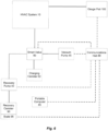
FIG. 6 is a schematic view of a system in accordance with another embodiment of the invention, including a recovery pump, a vacuum pump, and acommunication hub 89, connected to a refrigeration circuit. -
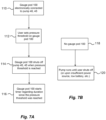
FIG. 7A is a flow chart illustrating operation of the gauge pod and the vacuum pump ofFIGS. 4 and5 , respectively. -
FIG. 7B is a flow chart illustrating operation of the vacuum pump ofFIG. 5 without the gauge pod. -
FIG. 8 is a flow chart illustrating an operation for performing work on the refrigeration circuit ofFIG. 1 using the system ofFIG. 1 . -
FIG. 9 is a flow chart illustrating a control scheme for the system ofFIG. 1 while performing work on the refrigeration circuit ofFIG. 1 . - Before any embodiments of the invention are explained in detail, it is to be understood that the invention is not limited in its application to the details of construction and the arrangement of components set forth in the following description or illustrated in the accompanying drawings. The invention is capable of other embodiments and of being practiced or of being carried out in various ways. Also, it is to be understood that the phraseology and terminology used herein is for the purpose of description and should not be regarded as limiting.
- With reference to
FIG. 1 , an air conditioning orrefrigeration circuit 10 includes anevaporator 15, acompressor 20, acondenser 25, and anexpansion valve 30. A refrigerant circulates through therefrigeration circuit 10, changing phases between liquid and vapor when passing through theevaporator 15 and thecondenser 25. Thecircuit 10 schematically illustrates a typical vapor-compression refrigeration cycle commonly known by those of ordinary skill in the art. HVAC systems, such as the illustratedair conditioning circuit 10, are commonly found in residential properties, commercial properties, vehicles, and many other systems. - When maintenance is to be performed on the
air conditioning circuit 10 of an HVAC system, eachcomponent air conditioning circuit 10 includes aport 35 to which arecovery pump 40 and avacuum pump 45 may be alternately or concurrently coupled to allow the refrigerant to be removed from or introduced to thecircuit 10. In some embodiments, therecovery pump 40 and thevacuum pump 45 are separate, individual components (FIG. 1 ), while in other embodiments, therecovery pump 40 and thevacuum pump 45 are integrated into a single housing or chassis such that therecovery pump 40 and thevacuum pump 45 may or may not be removably coupled to each other. Still, in other embodiments, therecovery pump 40 and thevacuum pump 45 may be integrated into a modular storage system, such as Milwaukee Tool's PACKOUT modular storage system. - With reference to
FIG. 2 , therecovery pump 40 includes amotor 50, apump 55 driven by themotor 50 that is operable to draw suction, and acontroller 58 for controlling operation of themotor 50. Thecontroller 58 includes acommunication interface 59 for communicating with other system components, which are described below, that interface with thecircuit 10. In the illustrated embodiment, thecommunication interface 59 is configured to send and receive a wireless signal, which is processed by thecontroller 58 and for sending an instruction and/or data to another system component interfacing with thecircuit 10. Thecommunication interface 59 may communicate with a network created between therecovery pump 40 and other system components interfacing with the circuit (e.g., using a cellular network, wide area network, local area network, etc.). Thecommunication interface 59 may also allow therecovery pump 40 to directly communicate with other system components interfacing with the circuit, such as using a short-wave radio communication protocol (e.g., BLUETOOTH). In some embodiments, the communication interface of thecontroller 58 may be an electrical port to which an electrical cable or wire is attached for communication with various components of thecircuit 10. - The
pump 55 of the illustrated embodiment is a multi-stage rotary vane pump. Themotor 50 is powered by an 18 volt Lithium-ion battery pack 60. In other embodiments, multiple battery packs 60 may be used to achieve a higher operating voltage (if used in series) or a higher capacity (if operating in parallel). In yet other embodiments, thebattery pack 60 may include a different nominal voltage (e.g., 12 volts, 24 volts, 80 volts, etc.). In yet other embodiments, therecovery pump 40 may include a power cord for connection to an external power source (e.g., AC power through a wall outlet). The illustratedmotor 50 is a brushless direct current (i.e., BLDC) motor. But, in other embodiments of therecovery pump 40, themotor 50 may be a brushed DC motor or an alternating current (i.e., AC) motor. Therecovery pump 40 includes an inlet port 62 (FIG. 1 ) for drawing the refrigerant into therecovery pump 40 and anoutlet port 63 for discharging the refrigerant from therecovery pump 40. - With reference to
FIG. 3 , thevacuum pump 45 includes amotor 65, apump 70 driven by themotor 65 that is operable to draw suction, and acontroller 73 for controlling operation of themotor 65. Thecontroller 73 also includes acommunication interface 74 for communicating with other system components, such as therecovery pump 40, that interface with thecircuit 10. Like thecommunication interface 59 in therecovery pump 40, thecommunication interface 74 is configured to send and receive a wireless signal, which is processed by thecontroller 73 and for sending an instruction and/or data to another system component interfacing with thecircuit 10. Thecommunication interface 74 can indirectly communicate with thecommunication interface 59 in therecovery pump 40 over a network, as described above, or thecommunication interface 74 can directly communicate with thecommunication interface 59 in the recoverpump 40 as described above. In some embodiments, the communication interface of thecontroller 73 may be an electrical port to which an electrical cable or wire is attached for communication with various components of thecircuit 10. - The
pump 70 of the illustrated embodiment is a rotary vane pump commonly known in the art. Themotor 65 is powered by an 18 volt lithium-ion battery pack 75. In other embodiments, multiple battery packs 75 may achieve a higher voltage (if used in series) or a higher capacity (if operating in parallel). In yet other embodiments, thebattery pack 75 may include a different nominal voltage (e.g., 12 volts, 24 volts, etc.). In yet other embodiments, thevacuum pump 45 may include a power cord for connection to an external power source (e.g., AC power through a wall outlet). The illustratedmotor 65 is a brushless direct current (i.e., BLDC) motor. But, in other embodiments of thevacuum pump 45, themotor 65 may be a brushed DC motor or an alternating current (i.e., AC) motor. Thevacuum pump 45 includes an inlet port 77 (FIG. 1 ) for drawing the refrigerant into thevacuum pump 45 and anoutlet port 78 for discharging to atmosphere. - With reference to
FIG. 1 , each of therecovery pump 40 and thevacuum pump 45, through their respective communication interfaces 59, 74, can communicate with a mobile electronic device or portable computer 85 (e.g., a smart phone, a tablet, a remote controller, etc.) via acommunication interface 87 in theportable computer 85. Thecommunication interface 87 can indirectly communicate with the communication interfaces 59, 74 in therecovery pump 40 and thevacuum pump 45, respectively, over a network. For example, the communication interfaces 59, 74 may send wireless signals to a communication hub 89 (as indicated by dashed lines) that subsequently relays the wireless signals to thecommunication interface 87 of theportable computer 85, as shown inFIG. 6 . In other embodiments, thecommunication interface 87 can directly communicate with the communication interfaces 59, 74 in therecovery pump 40 and thevacuum pump 45, respectively, through a wired connection. Theportable computer 85 is capable of displaying, to a user remotely situated from thepumps pumps 40, 45 (e.g., power status, motor speed, battery level status, inlet and/or outlet port pressure and/or vacuum, service messages and/or warnings, total elapsed time, refrigerant levels, date and time, etc.) and/or one or more characteristic values of the circuit 10 (e.g., pressure, vacuum, etc.). - The
portable computer 85 may also be used to transmit instructions, via thecommunication interface 87, to either of thecontrollers pump 40 and thevacuum pump 45, respectively. - Although not shown, in some embodiments, an electronic display may be provided on-board the
recovery pump 40 and/or thevacuum pump 45 to communicate to a user one or more performance parameters of thepumps 40, 45 (e.g., power status, motor speed, battery level status, inlet and/or outlet port pressure and/or vacuum, service messages and/or warnings, total elapsed time, refrigerant levels, date and time, etc.) and/or one or more characteristic values of the circuit 10 (e.g., pressure, vacuum, etc.). Also, in some embodiments, therecovery pump 40 and/or thevacuum pump 45 may include on-board gauges to display the pressure (or vacuum) measured at theport 35 with a first gauge and the amount of refrigerant being discharged or introduced into thecircuit 10 with a second gauge. The first and second gauges include a respective scale and level of precision to provide the user with proper accuracy. - With reference to
FIG. 1 , an accessory, such as an electrically actuated, multi-position "smart"valve 80, is fluidly connected to theport 35. Thesmart valve 80 includes an on-board controller, which has acommunication interface 84 for wirelessly communicating with other system components, such as therecovery pump 40 and thevacuum pump 45, that interface with thecircuit 10. In other embodiments, thecommunication interface 84 wirelessly communicates with the communication hub 89 (as indicated by dashed lines) that relays signals from thesmart valve 80 to other system components, as shown inFIG. 6 . The illustratedsmart valve 80 is a two-position valve capable of selectively fluidly communicating either therecovery pump 40 or thevacuum pump 45 with thecircuit 10 through theport 35. Specifically, thesmart valve 80 of the illustrated embodiment is an electrically actuated (e.g., by a solenoid) valve that is operated by the on-board controller to alternate fluid communication between therecovery pump 40 and thevacuum pump 45 with theport 35. That said, therecovery pump 40 and thevacuum pump 45 are not capable of simultaneously being in fluid communication with theport 35. In other embodiments, therecovery pump 40 and thevacuum pump 45 each have separatesmart valves 80 that are either at therespective inlet ports pump smart valve 80 may also measure flow rate of the refrigerant via a sensor (e.g., flowmeter, etc.) to be able to determine the amount of refrigerant contained in thecanister 90. - With continued reference to
FIG. 1 , therecovery pump 40 is configured to be in fluid communication with afluid recovery canister 90. Thefluid recovery canister 90 defines an empty tank capable of receiving a volume of fluid or refrigerant. In the illustrated embodiment, thefluid recovery canister 90 is positioned on a measuring accessory orscale 95 that measures the weight of thefluid recovery canister 90 via a sensor (e.g., force gauge, load cell, etc.), which is indicative to the amount of refrigerant contained with thecanister 90. Thescale 95 also includes an on-board controller, which has acommunication interface 97 for wirelessly communicating with other system components, such as therecovery pump 40 and thevacuum pump 45, that interface with thecircuit 10 in the same manner as described above. In other embodiments, thecommunication interface 97 wirelessly communicates with the communication hub 89 (as indicated by dashed lines) that relays signals from thescale 95 to other system components, as shown inFIG. 6 . Specifically, thescale 95 can communicate with therecovery pump 40 via itscommunication interface 59 for monitoring the amount of refrigerant in thecanister 90. In some embodiments, thescale 95 is incorporated with therecovery pump 40 to form a single integrated unit. While in the illustrated embodiment the measuring device is ascale 95 for measuring weight, in other embodiments, the measuring device may alternatively measure flow rate of the refrigerant via a sensor (e.g., flowmeter, etc.) to be able to determine the amount of refrigerant contained in thecanister 90. A chargingcanister 92, defining a refrigerant tank capable of filling thecircuit 10, may be connected to thesmart valve 80 directly (FIG. 6 ) once thefluid recovery canister 90 has recovered refrigerant from thecircuit 10. - With continued reference to
FIG. 1 , another accessory, such as agauge pod 100, is fluidly connected to theconduit line 17 and is capable of measuring the pressure (or vacuum) via a sensor (e.g., pressure transducer, etc.) in the conduit lines 17, 22, 27, 32 of theair conditioning circuit 10. As illustrated, thegauge pod 100 is fluidly connected to aport 105 of theconduit line 17 that is physically separate or disposed remotely from theport 35 where therecovery pump 40 and thevacuum pump 45 are connected. By locating thegauge pod 100 far away from theport 35, the total pressure detected by thegauge pod 100 is a more accurate reflection of static pressure in thelines circuit 10 because the effects of dynamic pressure of the flowing gas at or near theport 35 are minimized. Thegauge pod 100 includes an on-board controller, which has acommunication interface 102 for wirelessly communicating with other system components, such as therecovery pump 40 and thevacuum pump 45, that interface with thecircuit 10 in the same manner as described above. In other embodiments, thecommunication interface 102 wirelessly communicates with the communication hub 89 (as indicated by dashed lines) that relays signals from thegauge pod 100 to other system components, as shown inFIG. 6 . - The
gauge pod 100 electronically communicates with therecovery pump 40 and thevacuum pump 45 by sending signals indicative of the pressure (or vacuum) measured by thegauge pod 100. Although thegauge pod 100 of the illustrated embodiment is in fluid communication with theconduit line 17, in other embodiments, thegauge pod 100 may alternatively be coupled to any of the conduit lines 17, 22, 27, 32 at a remote location from theport 35. - During operation, the refrigerant in the
circuit 10 is first drained and collected prior to a user performing maintenance on thecircuit 10. In order to do so, the user connects thesmart valve 80 to theport 35, thegauge pod 100 to theport 105, and therecovery pump 40 and thevacuum pump 45 to thesmart valve 80, as indicated bystep 140 ofFIG. 9 . Subsequently, therecovery pump 40 and thevacuum pump 45 are connected with thesmart valve 80 via thedual inlets ports recovery pump 40, thevacuum pump 45, thesmart valve 80, thescale 95, and thegauge pod 100 electronically communicate with each other, via the respective communication interfaces 59, 74, 84, 97, 102 or through thecommunication hub 89, and assume a "ready" state. The state of each of these components can be communicated to the user via theportable computer 85. When the user is ready to recover the refrigerant from thecircuit 10, the user may initiate operation of therecovery pump 40 by sending an instruction to thecontroller 58 with theportable computer 85, as indicated bystep 142. Alternatively, the user may initiate operation of therecovery pump 40 by manipulating controls on a control panel on-board therecovery pump 40. - The
smart valve 80 is actuated to place therecovery pump 40 in fluid communication with thecircuit 10 and activates the motor 50 (and therefore the pump 55) of therecovery pump 40 to remove refrigerant from thecircuit 10 when therecovery pump 40 in a fluid removal state. The refrigerant that is being removed from thecircuit 10 travels through theport 35, thesmart valve 80, theinlet port 62 of therecovery pump 40, discharged throughoutlet port 63, and is then stored and collected in thefluid recovery canister 90, thus increasing the weight of thecanister 90. Therecovery pump 40 is configured to detect the type of or characteristics of the refrigerant being removed (e.g., ASHRAE Number R134a, R32, R410a, etc.) during collection of the refrigerant via a sensor (e.g., viscosity sensor). In other embodiments, the user manually selects/inputs the type of refrigerant being used in thecircuit 10 with a selector knob, a digital display, or other means. Thescale 95 upon which thecanister 90 is disposed monitors the weight of thecanister 90 and sends a signal to therecovery pump controller 58 indicative of the weight of thecanister 90. In one embodiment, when thecontroller 58 detects that the weight of thecanister 90 has reached a maximum weight threshold, thecontroller 58 stops the motor 50 (and therefore the pump 55), discontinues the transfer of the refrigerant into thecanister 90, and begins transferring the refrigerant into an alternate canister (not shown). In other embodiments, thecontroller 58 deactivates themotor 50 and thepump 55 when the weight of thecanister 90, as communicated by thescale 95, has reached the maximum weight threshold. - Meanwhile, as indicated by
step 110 ofFIG. 7A , thegauge pod 100 is also sending signals to therecovery pump controller 58 for monitoring the pressure within the circuit 10 (e.g., conduit lines 17, 22, 27, 32) when the refrigerant is being recovered into thecanister 90. Thegauge pod 100 compares the pressure within thecircuit 10 with the pressure threshold set by the user, as indicated bystep 112. When thegauge pod 100 sends a signal to therecovery pump controller 58 indicative that the pressure in thecircuit 10 has reached or dropped below a pressure threshold, therecovery pump 40 is deactivated, as indicated bystep 114. Therecovery pump 40 may be deactivated due to the pressure threshold being reached even though the maximum weight threshold has not been reached. Once the pressure threshold has been reached, thegauge pod 100 begins a timer to count the duration since the pressure threshold was reached, as indicated bystep 116. If thegauge pod 100 is not electrically connected to therecovery pump controller 58, as indicated bystep 118 ofFIG. 7B , then therecovery pump 40 runs until the user deactivates therecovery pump 40, as indicated bystep 120. - Once the
recovery pump 40 is deactivated in response to either the maximum weight threshold or the pressure threshold, an indication is provided to the user through either the on-board electronic display or theportable computer 85, as indicated bystep 144 ofFIG. 9 . Such an indication may be, for example, tactile (e.g., vibration), audible (e.g., a warning tone or beeps), visual (e.g., a warning light), or a combination thereof. Generally, the indication is indicative that the refrigerant has been recovered from theair conditioning circuit 10, as indicated bystep 122, and that the user is allowed to service or perform maintenance on thecircuit 10, as indicated bystep 124. Occasionally, thecanisters circuit 10, as indicated bystep 126. Other indications may also be provided to the user for monitoring various performance parameters during operation. For example, an indication may be provided to the user when thebattery 60 has reached or drops below a charge threshold. In response to the charge threshold of thebattery 60 being reached, thecontroller 58 is configured to deactivate themotor 50 and close thesmart valve 80 to seal thecircuit 10 from ingress of contaminants. In other embodiments, a biased-closed valve is provided that seals the circuit. In another embodiment, a capacitive circuit is provided that stores a charge sufficient to power a valve to close and seal the circuit once the charge threshold is reached. Also, an indication may be provided to the user, through either the on-board electronic display or theportable computer 85, when themotor 50 reaches a load threshold. In this case, the indication of the load threshold being reached may be indicative of an issue with therecovery pump 40 or that therecovery pump 40 may need servicing (e.g., oil change, low oil, etc.). Further, an indication may be provided to the user, through either the on-board electronic display or theportable computer 85, when a potential leak is detected. In response to a potential leak being detected, therecovery pump 40 enters a leak detection mode, as indicated bystep 128, where therecovery pump 40 deactivates for a predetermined time period. Once the predetermined time period has elapsed, therecovery pump 40 measures the pressure in thecircuit 10, as indicated bystep 130, and compares the measured pressure to the pressure in thecircuit 10 upon entering the leak detection mode. If the pressure changed throughout the predetermined time period, as indicated bystep 130, therecovery pump 40 indicates to a user, through either the on-board electronic display or theportable computer 85, that there is a leak in the system. In one embodiment, thevacuum pump 45 and/orrecovery pump 40 will send, e.g., wirelessly transmit, a notification to a user, e.g., to a user's smartphone or other wireless device. In other embodiments, thecontroller 58 of therecovery pump 40 may alternatively close thesmart valve 80 upon therecovery pump 40 entering the leak detection mode. - Upon completion of the maintenance on the
circuit 10, the user may perform a gas purge of thecircuit 10, as indicated bystep 128. In one embodiment, therecovery pump controller 58 initiates release of Nitrogen or other gas into thecircuit 10 to purge thecircuit 10 of contaminants (e.g., moisture). The majority of the contaminants are removed from thecircuit 10 upon completion of the Nitrogen purge and the run cycle of therecovery pump 40. - Following the Nitrogen (or other gas) purge, the
smart valve 80 is controlled (by one of thecontrollers 58, 73) to place thevacuum pump 45 in fluid communication with thecircuit 10, as indicated bystep 146 ofFIG. 9 . Thereafter, thevacuum pump controller 73 activates the motor 65 (and therefore the pump 70) to draw a deep vacuum in thecircuit 10 to remove gas (e.g., air) and any contaminants (e.g., moisture, etc.) remaining in thecircuit 10. Thegauge pod 100 monitors the pressure in thecircuit 10 once thevacuum pump 45 is activated. When thegauge pod 100 sends a signal to thecontroller 73 indicative that the pressure in thecircuit 10 has reached a predetermined pressure (in this instance, vacuum) threshold, thevacuum pump 45 is deactivated and thesmart valve 80 may be closed, as indicated bystep 148. In some embodiments, the vacuum threshold is the same regardless of which pump 40, 45 is running, whereas in other embodiments, the pressure threshold is different depending which pump 40, 45 is running. - The same performance parameters of the
vacuum pump 45 and characteristic values of thecircuit 10 that were monitored during activation of therecovery pump 40, as described above, may also be monitored while thevacuum pump 45 is activated. A corresponding indication (e.g., tactile, audible, visual, etc.) is provided to the user, through either an electronic display on-board thevacuum pump 45 or theportable computer 85, in response to any of the performance parameters and/or characteristic values of the circuit reaching a predetermined threshold during operation of thevacuum pump 45. - Once the
vacuum pump 45 evacuates thecircuit 10 and the user is prompted to confirm proceeding to the next step, thesmart valve 80 is instructed (through a signal received from one of thecontrollers 58, 73) to place therecovery pump 40 in fluid communication with thecircuit 10, and therecovery pump controller 58 re-activates themotor 50 and thepump 55, as indicated bystep 150 ofFIG. 9 . This time, however, therecovery pump 40 introduces (i.e., pumps) refrigerant into thecircuit 10 through theoutlet port 63 when therecovery pump 40 in a fluid supply state, as indicated bystep 134 ofFIG.8 and step 152 ofFIG. 9 . In one embodiment, the refrigerant that was previously removed from thecircuit 10 is reintroduced into thecircuit 10. In other embodiments, a new fluid or refrigerant from a new canister (charging canister 92) on thescale 95 is introduced into thecircuit 10. When thescale 95 determines that a weight of the chargingcanister 92 or thecollection canister 90 has reached a minimum weight threshold (e.g., indicative that the refrigerant has been pumped into the circuit 10) thecontroller 58 deactivates therecovery pump 40. An indication (e.g., tactile, audible, visual, etc.) is provided to the user that the weight threshold has been reached (as indicated bystep 154 ofFIG. 9 ), through either the electronic display on-board the recoverpump 40 or theportable computer 85, to indicate that thecircuit 10 has been refilled with the refrigerant and the process is complete, as indicated bystep 136 ofFIG. 8 . - As refrigerant is introduced into the
circuit 10, thecanister canister canister heater 107, such as a hot plate or a warming blanket may be provided on thescale 95 to heat thecanister 90. In other embodiments, theheater 107 may be an exhaust fan provided adjacent thescale 95 that blows hot air exhausted from themotor 50 across thecanister 90. - Accordingly, each of the
recovery pump 40 and thevacuum pump 45 can communicate with each other to receive information therefrom and to automatically control the operation of various accessories interfacing with theair conditioning circuit 10, such as (in addition to thepumps 40, 45) thesmart valve 80, thescale 95, thegauge pod 100. Thus, only minimal input is required from the user, through either an electronic display on-board thepumps portable computer 85, to initiate a refrigerant recovery, conduit evacuation, and refrigerant replacement processes. - Aspects of the present disclosure may be as set out in the following numbered clauses.
- Clause 1. A system attachable to a refrigeration circuit, the system comprising:
- a recovery pump attachable to the refrigeration circuit to remove refrigerant therefrom, the recovery pump including
- a pump,
- an electric motor for driving the pump,
- a battery pack for providing power to the electric motor, and
- a recovery pump controller for controlling the operation of the electric motor, the recovery pump controller having a first communication interface; and
- an accessory attachable to the refrigeration circuit concurrently with the recovery pump, the accessory including
- a sensor for detecting a characteristic value of the refrigeration circuit, and
- an accessory controller electrically connected with the sensor to receive a signal therefrom corresponding with the characteristic value of the refrigeration circuit, the accessory controller having a second communication interface to communicate the signal to the recovery pump controller via the first and second wireless interfaces,
- wherein the recovery pump controller is operable to control the operation of the electric motor based upon the signal received from the accessory.
- Clause 2. The system of clause 1, wherein the pump is operable in a fluid removal state, in which the pump removes the refrigerant from the refrigeration circuit when the electric motor is activated, and in a fluid supply state, in which the pump supplies the refrigerant to the refrigeration circuit when the electric motor is activated.
- Clause 3. The system of clause 2, wherein the recovery pump further comprises a recovery pump sensor disposed proximate at least one of a fluid inlet or a fluid outlet for detecting a type of the refrigerant during the fluid removal state.
- Clause 4. The system of clause 2, wherein the accessory includes an electrically actuated fluid valve coupled between the pump and the refrigeration circuit to selectively place the pump in fluid communication with the refrigeration circuit.
- Clause 5. The system of clause 4, wherein the electrically actuated fluid valve is actuated to place the pump in fluid communication with the refrigeration circuit, and wherein the electrically actuated fluid valve activates the electric motor to remove the refrigerant from the refrigeration circuit during the fluid removal state.
- Clause 6. The system of clause 2, further including a collection canister that is in fluid communication with the pump for storing the refrigerant extracted from the refrigeration circuit during the fluid removal state.
- Clause 7. The system of clause 6, wherein the accessory includes a measuring accessory that is a scale to measure the weight of the refrigerant stored in the collection canister from the refrigeration circuit.
- Clause 8. The system of clause 7, wherein the accessory controller is configured to transmit the signal to the recovery pump controller to deactivate the electric motor in response to the measuring accessory detecting that the collection canister has reached a maximum weight threshold.
- Clause 9. The system of clause 8, wherein the accessory controller is configured to transmit the signal to a portable computer indicating to a user that the maximum weight threshold has been reached.
-
Clause 10. The system of clause 8, wherein the accessory controller is configured to transmit the signal to the recovery pump controller to reactivate the electric motor for supplying the refrigeration circuit with the refrigerant from the collection canister during the fluid supply state. - Clause 11. The system of
clause 10, further comprising a heater for increasing the temperature of the collection canister during the fluid supply state. - Clause 12. The system of clause 11, wherein the heater is a resistive heating element coupled to the collection canister.
- Clause 13. The system of clause 2, wherein the accessory includes a gauge accessory that is attachable to the refrigeration circuit and is disposed remotely from the recovery pump.
- Clause 14. The system of clause 13, wherein the accessory controller is configured to transmit the signal to the recovery pump controller indicative of the pressure within the refrigeration circuit proximate the gauge accessory.
-
Clause 15. The system of clause 14, wherein the pump is deactivated in response to the signal received from the accessory controller corresponding to the pressure in the refrigeration circuit being equal or below a pressure threshold. - Clause 16. The system of clause 1, wherein the battery pack is a Lithium-ion battery pack.
-
Clause 17. The system of clause 1, further comprising an electronic display for communicating to the user at least one of a performance parameter of the recovery pump or a characteristic value associated with the refrigeration system. - Clause 18. The system of clause 1, wherein the performance parameter includes a load value of the electric motor.
- Clause 19. The system of clause 1, wherein the first communication interface of the recovery pump controller is a first wireless interface and the second communication interface of the accessory controller is a second wireless interface.
-
Clause 20. A system attachable to a refrigeration circuit, the system comprising: - a recovery pump attachable to the refrigeration circuit to remove refrigerant therefrom, the recovery pump including
- a pump,
- an electric motor for driving the pump, and
- a recovery pump controller for controlling the operation of the electric motor, the recovery pump controller having a first communication interface; and
- an accessory attachable to the refrigeration circuit concurrently with the recovery pump, the accessory including
- a sensor for detecting a characteristic value of the refrigeration circuit, and
- an accessory controller electrically connected with the sensor to receive a signal therefrom corresponding with the characteristic value of the refrigeration circuit, the accessory controller having a second communication interface to communicate the signal to the recovery pump controller via the first and second communication interfaces,
- wherein the recovery pump controller is operable to control the operation of the electric motor based upon the signal received from the accessory, and
- wherein the accessory includes at least one of
- an electrically actuated fluid valve coupled between the pump and the refrigeration circuit to selectively place the pump in fluid communication with the refrigeration circuit, or
- a gauge accessory that is attachable to the refrigeration circuit and is disposed remotely from the recovery pump, the signal being indicative of the pressure within the refrigeration circuit proximate the gauge accessory.
- Clause 21. The system of
clause 20, wherein the pump is operable in a fluid removal state, in which the pump removes the refrigerant from the refrigeration circuit when the electric motor is activated, and in a fluid supply state, in which the pump supplies the refrigerant to the refrigeration circuit when the electric motor is activated. -
Clause 22. The system of clause 21, wherein the recovery pump further comprises a recovery pump sensor disposed proximate at least one of a fluid inlet or a fluid outlet for detecting a type of the refrigerant during the fluid removal state. - Clause 23. The system of clause 21, wherein the electrically actuated fluid valve activates the electric motor to remove the refrigerant from the refrigeration circuit during the fluid removal state.
- Clause 24. The system of clause 21, further including a collection canister that is in fluid communication with the pump for storing the refrigerant extracted from the refrigeration circuit during the fluid removal state.
-
Clause 25. The system of clause 24, wherein the accessory includes a measuring accessory that is a scale to measure the weight of the refrigerant stored in the collection canister from the refrigeration circuit. - Clause 26. The system of
clause 25, wherein the accessory controller is configured to transmit the signal to the recovery pump controller to deactivate the electric motor in response to the measuring accessory detecting that the collection canister has reached a maximum weight threshold. -
Clause 27. The system of clause 26, wherein the accessory controller is configured to transmit the signal to a portable computer indicating to a user that the maximum weight threshold has been reached. - Clause 28. The system of clause 26, wherein the accessory controller is configured to transmit the signal to the recovery pump controller to reactivate the electric motor for supplying the refrigeration circuit with the refrigerant from the collection canister during the fluid supply state.
- Clause 29. The system of clause 28, further comprising a heater for increasing the temperature of the collection canister during the fluid supply state.
-
Clause 30. The system of clause 29, wherein the heater is a resistive heating element coupled to the collection canister. - Clause 31. The system of clause 21, wherein the accessory controller is configured to transmit the signal to the recovery pump controller indicative of the pressure within the refrigeration circuit proximate the gauge accessory.
-
Clause 32. The system of clause 31, wherein the pump is deactivated in response to the signal received from the accessory controller corresponding to the pressure in the refrigeration circuit being equal or below a pressure threshold. - Clause 33. The system of
clause 20, further comprising a battery pack for providing power to the electric motor. - Clause 34. The system of
clause 20, further comprising an electronic display for communicating to the user at least one of a performance parameter of the recovery pump or a characteristic value associated with the refrigeration system. -
Clause 35. The system of clause 34, wherein the performance parameter includes a load value of the electric motor. - Clause 36. The system of
clause 20, wherein the first communication interface of the recovery pump controller is a first wireless interface and the second communication interface of the accessory controller is a second wireless interface. - Clause 37. A system attachable to a refrigeration circuit, the system comprising:
- a vacuum pump attachable to the refrigeration circuit to remove fluid therefrom, the vacuum pump including
- a pump,
- an electric motor for driving the pump, and
- a vacuum pump controller for controlling the operation of the electric motor, the vacuum pump controller having a first communication interface; and
- an accessory attachable to the refrigeration circuit concurrently with the vacuum pump, the accessory includes at least one of
- an electrically actuated fluid valve coupled between the pump and the refrigeration circuit to selectively place the pump in fluid communication with the refrigeration circuit, or
- a gauge accessory attachable to the refrigeration circuit concurrently with the vacuum pump, the gauge accessory including
- a sensor for detecting pressure within the refrigeration circuit, and
- an accessory controller electrically connected with the sensor to receive a signal therefrom corresponding with the pressure of the refrigeration circuit, the accessory controller having a second communication interface to communicate the signal to the vacuum pump controller via the first and second communication interfaces,
- wherein the vacuum pump controller is operable to control the operation of the electric motor based upon the signal received from the gauge accessory.
- Clause 38. The system of clause 37, wherein the pump is operable in a fluid removal state, in which the pump removes a fluid from the refrigeration circuit when the electric motor is activated.
- Clause 39. The system of clause 38, wherein the electrically actuated fluid valve and the gauge accessory are provided.
-
Clause 40. The system of clause 39, wherein the electrically actuated fluid valve includes a controller with a communication interface for communicating with the vacuum pump. - Clause 41. The system of clause 39, wherein the electrically actuated fluid valve is actuated to place the pump in fluid communication with the refrigeration circuit, and wherein the electrically actuated fluid valve activates the electric motor to remove the fluid from the refrigeration circuit and discharge the fluid to atmosphere during the fluid removal state.
- Clause 42. The system of clause 37, wherein the controller is configured to communicate with a portable computer via the communication interface to transmit a performance parameter of the vacuum pump to the user and to receive instructions inputted by the user to remotely control operation of the vacuum pump.
- Clause 43. The system of clause 37, wherein the battery pack is a Lithium-ion battery pack.
- Clause 44. The system of clause 37, further comprising an electronic display for communicating to the user at least one of a performance parameter of the vacuum pump or a characteristic value associated with the refrigeration circuit.
-
Clause 45. The system of clause 44, wherein the performance parameter includes a load value of the electric motor. - Clause 46. The system of clause 37, wherein the first communication interface of the vacuum pump controller is a first wireless interface and the second communication interface of the accessory controller is a second wireless interface.
- Clause 47. A system attachable to a refrigeration circuit, the system comprising:
- a recovery pump attachable to the refrigeration circuit to remove refrigerant therefrom, the recovery pump including
- a pump,
- an electric motor for driving the pump,
- a battery pack for providing power to the electric motor, and
- a recovery pump controller for controlling the operation of the electric motor, the recovery pump controller having a communication interface; and
- a vacuum pump attachable to the refrigeration system concurrently with the recovery pump to create a vacuum in the refrigeration circuit, the vacuum pump including
- a pump,
- an electric motor for driving the pump,
- a battery pack for providing power to the electric motor, and
- a vacuum pump controller for controlling the operation of the electric motor, the vacuum pump controller having a communication interface,
- wherein the recovery pump controller and the vacuum pump controller are capable of bi-directional communication via the respective communication interfaces to control operation of the electric motors in the respective recovery pump and the vacuum pump.
- a recovery pump attachable to the refrigeration circuit to remove refrigerant therefrom, the recovery pump including
- Clause 48. The system of clause 47, wherein the pump of the recovery pump is operable in a fluid removal state, in which the pump removes the refrigerant from the refrigeration circuit when the electric motor of the recovery pump is activated, and in a fluid supply state, in which the pump of the recovery pump supplies the refrigerant to the refrigeration system when the electric motor of the recovery pump is activated.
- Clause 49. The system of clause 48, wherein the pump of the vacuum pump is operable in a fluid removal state, in which the pump removes a gas from the refrigeration circuit when the electric motor of the vacuum pump is activated.
-
Clause 50. The system of clause 49, further comprising an electrically actuated fluid valve to selectively place the recovery pump and the vacuum pump in fluid communication with the refrigeration circuit. - Clause 51. The system of
clause 50, wherein the electrically actuated fluid valve is a two-position valve such that the refrigeration circuit is in fluid communication with one of the recovery pump and the vacuum pump at a time. - Clause 52. The system of
clause 50, wherein the electrically actuated fluid valve includes a controller with a communication interface for communicating with the recovery pump and the vacuum pump. - Clause 53. The system of
clause 50, wherein the electrically actuated fluid valve is actuated to a first position to place the pump of the recovery pump in fluid communication with the refrigeration circuit, and wherein the electrically actuated fluid valve activates the electric motor of the recovery pump to remove the refrigerant from the refrigeration circuit during the fluid removal state, and wherein the electrically actuated fluid valve is actuated to a second position to place the pump of the vacuum pump in fluid communication with the refrigeration circuit, and wherein the electrically actuated fluid valve activates the electric motor of the vacuum pump to remove the gas from the refrigeration circuit during the fluid removal state. - Clause 54. The system of
clause 50, further comprising a collection canister that is in fluid communication with the pump of the recovery pump for storing the refrigerant extracted from the refrigeration circuit during the fluid removal state. -
Clause 55. The system of clause 54, wherein the electrically actuated fluid valve is actuated to place the pump of the recovery pump in fluid communication with the refrigeration circuit, and wherein the electrically actuated fluid valve activates the electric motor of the recovery pump to supply the refrigeration circuit with the refrigerant from the collection canister during the fluid supply state. - Clause 56. The system of
clause 55, further comprising a heater to increase the temperature of the collection canister during the fluid supply state - Clause 57. The system of clause 56, wherein the heater is a resistive heating element coupled to the collection canister.
-
Clause 58. The system of clause 54, further comprising a measuring accessory including a controller having a communication interface for communicating with the recovery pump and the vacuum pump a characteristic value associated with the refrigeration circuit. -
Clause 59. The system ofclause 58, wherein the measuring accessory is a scale to measure the weight of the refrigerant stored in the collection canister from the refrigeration circuit. -
Clause 60. The system ofclause 59, wherein the controller of the measuring accessory is configured to transmit a signal to the recovery pump to deactivate the electric motor in response to the measuring accessory detecting that the collection canister has reached a maximum weight threshold. - Clause 61. The system of
clause 60, wherein the controller of the measuring accessory is configured to transmit a signal to the user indicating that the maximum weight threshold has been reached. -
Clause 62. The system of clause 47, further comprising a gauge accessory that is attachable to the refrigeration circuit and is disposed remotely from the recovery pump and the vacuum pump. -
Clause 63. The system ofclause 62, wherein the gauge accessory includes a controller having a communication interface for communicating a characteristic value associated with the refrigeration circuit with at least one of the recovery pump or the vacuum pump. - Clause 64. The system of
clause 63, wherein the controller of the gauge accessory is configured to send a signal to at least one of the recovery pump or the vacuum pump indicative of the pressure of the refrigeration circuit. -
Clause 65. The system of clause 64, wherein the pump of the recovery pump is deactivated in response to the signal received from the controller of the gauge accessory corresponding to the pressure in the refrigeration circuit being equal or below a pressure threshold. - Clause 66. The system of clause 47, wherein the battery pack for the recovery pump and the battery pack for the vacuum pump are both Lithium-ion battery packs.
- Clause 67. The system of clause 47, further comprising an electronic display for communicating to the user at least one of a performance parameter of the recovery pump and the vacuum pump or a characteristic value associated with the refrigeration circuit.
- Clause 68. The system of clause 47, wherein the first communication interface of the recovery pump controller is a first wireless interface and the second communication interface of the accessory controller is a second wireless interface.
- Clause 69. A system attachable to a refrigeration circuit, the system comprising:
- a recovery pump attachable to the refrigeration circuit to remove refrigerant therefrom, the recovery pump including a first pump, a first electric motor for driving the first pump, and a first battery pack for providing power to the first electric motor; and
- a vacuum pump attachable to the refrigeration system to create a vacuum therein, the vacuum pump including a second pump, a second electric motor for driving the second pump, and a second battery pack for providing power to the second electric motor,
- wherein the first and second battery packs are interchangeable to provide power to the recovery pump and the vacuum pump.
-
Clause 70. The system of clause 69, wherein the first pump is operable in a fluid removal state, in which the first pump removes the refrigerant from the refrigeration circuit when the first electric motor is activated, and in a fluid supply state, in which the first pump supplies the refrigerant to the refrigeration circuit when the first electric motor is activated. - Clause 71. The system of
clause 70, wherein the second pump is operable in a fluid removal state, in which the second pump removes a gas from the refrigerant circuit when the second electric motor is activated. - Clause 72. The system of clause 71, further comprising an electrically actuated fluid valve to selectively place the recovery pump and the vacuum pump in fluid communication with the refrigeration circuit.
-
Clause 73. The system of clause 72, wherein the electrically actuated fluid valve is a two-position valve such that the refrigeration circuit is in fluid communication with one of the recovery pump and the vacuum pump at a time. -
Clause 74. The system of clause 72, wherein the electrically actuated fluid valve includes a controller with a wireless interface for communicating with the recovery pump and the vacuum pump. -
Clause 75. The system of clause 72, wherein the electrically actuated fluid valve is actuated to a first position to place the first pump in fluid communication with the refrigeration system, and wherein the electrically actuated fluid valve activates the first electric motor to remove the refrigerant from the refrigeration circuit during the fluid removal state, and wherein the electrically actuated fluid valve is actuated to a second position to place the second pump in fluid communication with the refrigeration circuit, and wherein the electrically actuated fluid valve activates the second electric motor to remove the gas from the refrigeration circuit during the fluid removal state. - Clause 76. The system of clause 72, further comprising a collection canister that is in fluid communication with the first pump for storing the refrigerant extracted from the refrigeration circuit during the fluid removal state.
-
Clause 77. The system of clause 76, wherein the electrically actuated fluid valve is actuated to place the first pump in fluid communication with the refrigeration circuit and activates the first electric motor to supply the refrigeration circuit with the refrigerant from the collection canister during the fluid supply state. -
Clause 78. The system ofclause 77, further comprising a heater for increasing the temperature of the collection canister during the fluid supply state. - Clause 79. The system of
clause 78, wherein the heater is a resistive heating element coupled to the collection canister. -
Clause 80. The system of clause 76, further comprising a measuring accessory including a controller having a wireless interface for communicating with the recovery pump and the vacuum pump a characteristic value associated with the refrigeration circuit. - Clause 81. The system of
clause 80, wherein the measuring accessory is a scale configured to measure the weight of the fluid stored in the collection canister from the refrigeration circuit. - Clause 82. The system of clause 81, wherein the controller of the measuring accessory is configured to send a signal to the recovery pump to deactivate the electric motor in response to the measuring accessory detecting that the collection canister has reached a maximum weight threshold.
- Clause 83. The system of clause 82, wherein the controller of the measuring accessory is configured to send a wireless signal to the user indicating that the maximum weight threshold has been reached.
-
Clause 84. The system of clause 69, further comprising a gauge accessory that is attachable to the refrigeration circuit and is disposed remotely from the recovery pump and the vacuum pump. -
Clause 85. The system ofclause 84, wherein the gauge accessory includes a controller having a wireless interface for communicating a characteristic value associated with the refrigeration circuit with at least one of the recovery pump or the vacuum pump. - Clause 86. The system of
clause 85, wherein the controller of the gauge accessory is configured to send a signal to at least one of the recovery pump or the vacuum pump indicative of the pressure of the refrigeration circuit. -
Clause 87. The system of clause 69, wherein the first and second battery packs are both Lithium-ion battery packs. - Clause 88. The system of clause 69, further comprising an electronic display for communicating to the user at least one of a performance parameter of the recovery pump and the vacuum pump or a characteristic value associated with the refrigeration circuit.
-
Clause 89. The system of clause 88, wherein the performance parameter includes a load value of at least one of the first electric motor or the second electric motor. -
Clause 90. A system attachable to a refrigeration circuit, the system comprising:- a pump assembly attachable to the refrigeration circuit, the pump assembly including a pump,
- an electric motor for driving the pump, and
- a pump controller for controlling the operation of the electric motor, the pump controller having a first communication interface;
- an accessory attachable to the refrigeration circuit concurrently with the pump assembly, the accessory including
- a sensor for detecting a characteristic value of the refrigeration circuit, and
- an accessory controller electrically connected with the sensor to receive a signal therefrom corresponding with the characteristic value of the refrigeration circuit, the accessory controller having a second communication interface; and
- a communication hub configured to receive the signal from the second communication interface of the accessory and transmit the signal to the pump controller via the first communication interface,
- wherein the pump controller is operable to control the operation of the electric motor based upon the signal received from the communication hub.
- a pump assembly attachable to the refrigeration circuit, the pump assembly including a pump,
- Clause 91. The system of
clause 90, wherein the pump assembly is operable in a fluid removal state, in which the pump removes a fluid from the refrigeration circuit when the electric motor is activated. -
Clause 92. The system of clause 91, further comprising an electrically actuated fluid valve coupled between the pump assembly and the refrigeration circuit to selectively place the pump assembly in fluid communication with the refrigeration circuit. - Clause 93. The system of
clause 92, wherein the electrically actuated fluid valve includes a controller with a communication interface for communicating with the vacuum pump. - Clause 94. The system of
clause 92, wherein the electrically actuated fluid valve is actuated to place the pump assembly in fluid communication with the refrigeration circuit, and wherein the electrically actuated fluid valve activates the electric motor to remove the fluid from the refrigeration circuit and discharge the fluid to atmosphere during the fluid removal state. -
Clause 95. The system ofclause 90, wherein the pump controller is configured to communicate with a portable computer via the first communication interface to transmit a performance parameter of the pump assembly to the user and to receive instructions inputted by the user to remotely control operation of the pump assembly. - Clause 96. The system of
clause 90, further comprising a battery pack for providing power to the electric motor. -
Clause 97. The system ofclause 90, further comprising an electronic display for communicating to the user at least one of a performance parameter of the pump assembly or a characteristic value associated with the refrigeration circuit. - Clause 98. The system of
clause 97, wherein the performance parameter includes a load value of the electric motor. - Clause 99. The system of
clause 90, wherein the first communication interface of the vacuum pump controller is a first wireless interface and the second communication interface of the accessory controller is a second wireless interface. -
Clause 100. A recovery pump for use with a refrigeration circuit, the recovery pump comprising:- a pump;
- an electric motor for driving the pump;
- a battery pack for providing power to the electric motor; and
- a controller for controlling the operation of the electric motor,
- wherein the controller includes a communication interface for communicating at least one of a performance parameter of the recovery pump to a user or a characteristic value associated with the refrigeration circuit to a user.
- Clause 101. The recovery pump of
clause 100, wherein the pump is operable in a fluid removal state, in which the pump removes a fluid from the refrigeration circuit when the electric motor is activated, and in a fluid supply state, in which the pump supplies a fluid to the refrigeration circuit when the electric motor is activated. -
Clause 102. The recovery pump of clause 101, further comprising an electrically actuated fluid valve coupled between the pump and the refrigeration circuit to selectively place the pump in fluid communication with the refrigeration circuit. - Clause 103. The recovery pump of
clause 102, wherein the electrically actuated fluid valve includes a controller with a communication interface for communicating with the controller of the recovery pump. - Clause 104. The recovery pump of
clause 102, wherein the electrically actuated fluid valve is actuated to place the pump in fluid communication with the refrigeration circuit, and wherein the electrically actuated fluid valve activates the electric motor to remove the fluid from the refrigeration circuit during the fluid removal state. -
Clause 105. The recovery pump of clause 104, further comprising a collection canister that is in fluid communication with the pump for storing fluid extracted from the refrigeration circuit during the fluid removal state. - Clause 106. The recovery pump of
clause 105, wherein the electrically actuated fluid valve is actuated to place the pump in fluid communication with the refrigeration circuit, and wherein the electrically actuated fluid valve activates the electric motor to supply the refrigeration system with fluid from the collection canister during the fluid supply state. -
Clause 107. The recovery pump of clause 106, further comprising a heater for increasing the temperature of the collection canister during the fluid supply state. - Clause 108. The recovery pump of
clause 107, wherein the heater is a resistive heating element coupled to the collection canister. - Clause 109. The recovery pump of
clause 105, further comprising a measuring accessory including a controller having a communication interface for communicating with the controller of the recovery pump a characteristic value associated with the refrigeration circuit. -
Clause 110. The recovery pump of clause 109, wherein the measuring accessory is a scale configured to measure the weight of the fluid stored in the collection canister from the refrigeration circuit. - Clause 111. The recovery pump of
clause 110, wherein the controller of the measuring accessory is configured to transmit a signal to the controller of the recovery pump to deactivate the electric motor in response to the measuring accessory detecting that the collection canister has reached a maximum weight threshold. -
Clause 112. The recovery pump of clause 111, wherein the controller of the measuring accessory is configured to transmit a signal to the user indicating that the maximum weight threshold has been reached. - Clause 113. The recovery pump of
clause 100, wherein the controller is configured to communicate with a portable computer via the communication interface to transmit a performance parameter of the recovery pump to the user and to receive instructions inputted by the user to remotely control operation of the recovery pump. -
Clause 114. The recovery pump ofclause 100, wherein the battery pack is a Lithium-ion battery pack. - Clause 115. The recovery pump of
clause 100, further comprising an electronic display for communicating to the user at least one of a performance parameter of the recovery pump or a characteristic value associated with the refrigeration circuit. -
Clause 116. The recovery pump of clause 115, wherein the performance parameter includes a load value of the electric motor. - Clause 117. The recovery pump of
clause 100, wherein the communication interface is a wireless interface. -
Clause 118. A vacuum pump for use with a refrigeration circuit, the vacuum pump comprising:- a pump,
- an electric motor for driving the pump,
- a battery pack for providing power to the electric motor, and
- a controller for controlling the operation of the electric motor,
- wherein the controller includes a communication interface for communicating at least one of a performance parameter of the vacuum pump to a user or a characteristic value associated with the refrigeration circuit to a user.
- Clause 119. The vacuum pump of
clause 118, wherein the pump is operable in a fluid removal state, in which the pump removes a fluid from the refrigeration circuit when the electric motor is activated. -
Clause 120. The vacuum pump of clause 119, further comprising an electrically actuated fluid valve coupled between the pump and the refrigeration circuit to selectively place the pump in fluid communication with the refrigeration circuit. - Clause 121. The vacuum pump of
clause 120, wherein the electrically actuated fluid valve includes a controller with a communication interface for communicating with the vacuum pump. -
Clause 122. The vacuum pump ofclause 120, wherein the electrically actuated fluid valve is actuated to place the pump in fluid communication with the refrigeration circuit, and wherein the electrically actuated fluid valve activates the electric motor to remove the fluid from the refrigeration circuit and discharge the fluid to atmosphere during the fluid removal state. - Clause 123. The vacuum pump of
clause 118, wherein the controller is configured to communicate with a portable computer via the communication interface to transmit a performance parameter of the vacuum pump to the user and to receive instructions inputted by the user to remotely control operation of the vacuum pump. -
Clause 124. The vacuum pump ofclause 118, wherein the battery pack is a Lithium-ion battery pack. - Clause 125. The vacuum pump of
clause 118, further comprising an electronic display for communicating to the user at least one of a performance parameter of the vacuum pump or a characteristic value associated with the refrigeration circuit. -
Clause 126. The vacuum pump ofclause 118, wherein the performance parameter includes a load value of the electric motor. - Clause 127. The vacuum pump of
clause 118, wherein the communication interface is a wireless interface. -
Clause 128. A method of performing work on a refrigeration circuit, the method comprising:- connecting a recovery pump, a vacuum pump, and an electrically actuated fluid valve to the refrigeration circuit;
- operating the recovery pump in a fluid removal state, in which the recovery pump removes the refrigerant from the refrigeration circuit;
- wirelessly communicating a first notification to a portable computer in response to termination of the fluid removal state; and
- wirelessly communicating an instruction via the portable computer to actuate the electrically actuated fluid valve to isolate the recovery pump from the refrigeration circuit and to place the vacuum pump in fluid communication with the refrigeration circuit.
- Clause 129. The method of
clause 128, further comprising purging the refrigeration circuit with Nitrogen gas to remove any remaining contaminants. -
Clause 130. The method ofclause 128, further comprising operating the vacuum pump to create a vacuum in the refrigeration circuit and wirelessly communicating a second notification to the portable computer in response to deactivation of the vacuum pump. - Clause 131. The method of
clause 130, further comprising deactivating the vacuum pump as a result of detecting a pressure threshold has been reached via a gauge accessory. -
Clause 132. The method ofclause 130, further comprising:- wirelessly communicating a second instruction via the portable computer to actuate the electrically actuated fluid valve to isolate the vacuum pump from the refrigeration circuit and to place the recovery pump in fluid communication with the refrigeration circuit; and
- operating the recovery pump in a fluid supply state, in which the recovery pump supplies the refrigerant to the refrigeration circuit.
- Clause 133. The method of
clause 132, further comprising deactivating the recovery pump as a result of detecting at least one of a weight threshold has been reached via a measuring accessory or a pressure threshold has been reached by a gauge accessory. -
Clause 134. The method ofclause 132, further comprising heating a refrigerant canister with a heating element during the fluid supply state.
Claims (15)
- A system attachable to a refrigeration circuit, the system comprising:a recovery pump attachable to the refrigeration circuit to remove refrigerant therefrom, the recovery pump includinga pump,an electric motor for driving the pump, anda recovery pump controller for controlling the operation of the electric motor, the recovery pump controller having a first communication interface; andan accessory attachable to the refrigeration circuit concurrently with the recovery pump, the accessory includinga sensor for detecting a characteristic value of the refrigeration circuit, andan accessory controller electrically connected with the sensor to receive a signal therefrom corresponding with the characteristic value of the refrigeration circuit, the accessory controller having a second communication interface to communicate the signal to the recovery pump controller via the first and second communication interfaces,wherein the recovery pump controller is operable to control the operation of the electric motor based upon the signal received from the accessory, andwherein the accessory includes at least one ofan electrically actuated fluid valve coupled between the pump and the refrigeration circuit to selectively place the pump in fluid communication with the refrigeration circuit, ora gauge accessory that is attachable to the refrigeration circuit and is disposed remotely from the recovery pump, the signal being indicative of the pressure within the refrigeration circuit proximate the gauge accessory.
- The system of claim 1, wherein the pump is operable in a fluid removal state, in which the pump removes the refrigerant from the refrigeration circuit when the electric motor is activated, and in a fluid supply state, in which the pump supplies the refrigerant to the refrigeration circuit when the electric motor is activated.
- The system of claim 2, wherein the recovery pump further comprises a recovery pump sensor disposed proximate at least one of a fluid inlet or a fluid outlet for detecting a type of the refrigerant during the fluid removal state.
- The system of claim 2, wherein the electrically actuated fluid valve activates the electric motor to remove the refrigerant from the refrigeration circuit during the fluid removal state.
- The system of claim 2, further including a collection canister that is in fluid communication with the pump for storing the refrigerant extracted from the refrigeration circuit during the fluid removal state.
- The system of claim 5, wherein the accessory includes a measuring accessory that is a scale to measure the weight of the refrigerant stored in the collection canister from the refrigeration circuit.
- The system of claim 6, wherein the accessory controller is configured to transmit the signal to the recovery pump controller to deactivate the electric motor in response to the measuring accessory detecting that the collection canister has reached a maximum weight threshold.
- The system of claim 7, wherein the accessory controller is configured to transmit the signal to a portable computer indicating to a user that the maximum weight threshold has been reached.
- The system of claim 7, wherein the accessory controller is configured to transmit the signal to the recovery pump controller to reactivate the electric motor for supplying the refrigeration circuit with the refrigerant from the collection canister during the fluid supply state.
- The system of claim 9, further comprising a heater for increasing the temperature of the collection canister during the fluid supply state.
- The system of claim 10, wherein the heater is a resistive heating element coupled to the collection canister.
- The system of claim 2, wherein the accessory controller is configured to transmit the signal to the recovery pump controller indicative of the pressure within the refrigeration circuit proximate the gauge accessory, and optionally, wherein the pump is deactivated in response to the signal received from the accessory controller corresponding to the pressure in the refrigeration circuit being equal or below a pressure threshold.
- The system of claim 1, further comprising a battery pack for providing power to the electric motor.
- The system of claim 1, further comprising an electronic display for communicating to the user at least one of a performance parameter of the recovery pump or a characteristic value associated with the refrigeration system, and optionally, wherein the performance parameter includes a load value of the electric motor.
- The system of claim 1, wherein the first communication interface of the recovery pump controller is a first wireless interface and the second communication interface of the accessory controller is a second wireless interface.
Applications Claiming Priority (3)
| Application Number | Priority Date | Filing Date | Title |
|---|---|---|---|
| US201862697767P | 2018-07-13 | 2018-07-13 | |
| EP19835077.9A EP3821183B1 (en) | 2018-07-13 | 2019-07-12 | System attachable to a refrigeration circuit and method of performing work on a refrigeration circuit |
| PCT/US2019/041714 WO2020014679A1 (en) | 2018-07-13 | 2019-07-12 | System including recovery pump and vacuum pump |
Related Parent Applications (1)
| Application Number | Title | Priority Date | Filing Date |
|---|---|---|---|
| EP19835077.9A Division EP3821183B1 (en) | 2018-07-13 | 2019-07-12 | System attachable to a refrigeration circuit and method of performing work on a refrigeration circuit |
Publications (2)
| Publication Number | Publication Date |
|---|---|
| EP4325144A2 true EP4325144A2 (en) | 2024-02-21 |
| EP4325144A3 EP4325144A3 (en) | 2024-04-03 |
Family
ID=69140081
Family Applications (2)
| Application Number | Title | Priority Date | Filing Date |
|---|---|---|---|
| EP24150323.4A Pending EP4325144A3 (en) | 2018-07-13 | 2019-07-12 | System including recovery pump and vacuum pump |
| EP19835077.9A Active EP3821183B1 (en) | 2018-07-13 | 2019-07-12 | System attachable to a refrigeration circuit and method of performing work on a refrigeration circuit |
Family Applications After (1)
| Application Number | Title | Priority Date | Filing Date |
|---|---|---|---|
| EP19835077.9A Active EP3821183B1 (en) | 2018-07-13 | 2019-07-12 | System attachable to a refrigeration circuit and method of performing work on a refrigeration circuit |
Country Status (4)
| Country | Link |
|---|---|
| US (3) | US11215176B2 (en) |
| EP (2) | EP4325144A3 (en) |
| CN (1) | CN112424546A (en) |
| WO (1) | WO2020014679A1 (en) |
Families Citing this family (3)
| Publication number | Priority date | Publication date | Assignee | Title |
|---|---|---|---|---|
| US11604019B2 (en) * | 2020-08-13 | 2023-03-14 | Emerson Climate Technologies, Inc. | Systems and methods for leak detection and refrigerant charging |
| KR102559317B1 (en) * | 2021-11-03 | 2023-07-26 | 한화오션 주식회사 | N2 Purging System And Method For Reliquefaction Apparatus In Ship |
| US12013138B2 (en) * | 2022-06-07 | 2024-06-18 | Tyco Fire & Security Gmbh | Working fluid eliminator for a heating, ventilation, and/or air conditioning (HVAC) system |
Family Cites Families (22)
| Publication number | Priority date | Publication date | Assignee | Title |
|---|---|---|---|---|
| US4441330A (en) * | 1980-12-01 | 1984-04-10 | Robinair Manufacturing Corporation | Refrigerant recovery and recharging system |
| US4805416A (en) * | 1987-11-04 | 1989-02-21 | Kent-Moore Corporation | Refrigerant recovery, purification and recharging system |
| US4856290A (en) * | 1988-07-26 | 1989-08-15 | Rodda Richard K | Refrigerant reclamation system |
| US5078756A (en) * | 1990-01-12 | 1992-01-07 | Major Thomas O | Apparatus and method for purification and recovery of refrigerant |
| US5875638A (en) * | 1993-05-03 | 1999-03-02 | Copeland Corporation | Refrigerant recovery system |
| US6260372B1 (en) * | 2000-02-01 | 2001-07-17 | Fredie Burke | Refrigerant recovery system and apparatus |
| CN101691963B (en) * | 2009-05-25 | 2011-11-16 | 广东志高空调有限公司 | Recycle system of air-conditioning outdoor machine refrigerant |
| IT1399282B1 (en) * | 2010-04-02 | 2013-04-11 | Texa Spa | RECHARGING / RECOVERY STATION OF A REFRIGERANT FLUID IN / FROM A VEHICLE CONDITIONING / AIR CONDITIONING PLANT |
| CN103140681B (en) * | 2010-10-01 | 2015-06-10 | 松下电器产业株式会社 | Electric compressor |
| US9464833B2 (en) * | 2012-05-10 | 2016-10-11 | Bosch Automotive Service Solutions Inc. | Refrigerant conversion kit and method for a refrigerant recovery unit |
| US9297564B2 (en) * | 2012-05-29 | 2016-03-29 | Bosch Automotive Service Solutions Inc. | Refrigerant recovery unit with diagnostic interface |
| US20140182684A1 (en) * | 2012-12-31 | 2014-07-03 | Service Solutions U.S. Llc | Refrigerant Removal Device and Method |
| WO2014165248A1 (en) * | 2013-03-12 | 2014-10-09 | Bosch Automotive Service Solutions Llc | Method and apparatus for improving the charge accuracy of a refrigerant recovery unit having a check valve device and temperature controlled service hoses |
| DE102014223956B4 (en) * | 2014-11-25 | 2018-10-04 | Konvekta Ag | Method for monitoring a charge of a refrigerant in a refrigerant circuit of a refrigeration system |
| CN204665777U (en) * | 2015-05-05 | 2015-09-23 | 上海佐竹冷热控制技术有限公司 | For the cold-producing medium filling recovery system of vehicle air conditioning test macro |
| CN104807262B (en) * | 2015-05-05 | 2017-11-03 | 上海佐竹冷热控制技术有限公司 | Refrigerant for vehicle air conditioning test system fills recovery system and method |
| US9874384B2 (en) * | 2016-01-13 | 2018-01-23 | Bergstrom, Inc. | Refrigeration system with superheating, sub-cooling and refrigerant charge level control |
| US10352600B2 (en) * | 2016-05-23 | 2019-07-16 | Snap-On Incorporated | Apparatus and method for a multi-phase vacuum-assisted recovery of refrigerant |
| CN106338166A (en) * | 2016-08-05 | 2017-01-18 | 浙江吉利控股集团有限公司 | Intelligent refrigerant charging and recovering device |
| US10473372B2 (en) * | 2016-11-10 | 2019-11-12 | Nortek Global HVAC, LLC | System and method for charging a refrigeration system |
| KR101727540B1 (en) | 2016-11-18 | 2017-04-17 | (주)메카스 | Refrigerant refining, recovery, leak testing, and injection integration |
| CN108168167B (en) * | 2018-02-01 | 2024-07-12 | 青岛绿环工业设备有限公司 | Refrigerant recovery, purification and filling all-in-one machine |
-
2019
- 2019-07-12 WO PCT/US2019/041714 patent/WO2020014679A1/en not_active Ceased
- 2019-07-12 EP EP24150323.4A patent/EP4325144A3/en active Pending
- 2019-07-12 EP EP19835077.9A patent/EP3821183B1/en active Active
- 2019-07-12 US US16/510,753 patent/US11215176B2/en active Active
- 2019-07-12 CN CN201980046975.9A patent/CN112424546A/en active Pending
-
2021
- 2021-12-14 US US17/550,548 patent/US12286968B2/en active Active
-
2025
- 2025-04-28 US US19/191,987 patent/US20250250978A1/en active Pending
Also Published As
| Publication number | Publication date |
|---|---|
| US20220099087A1 (en) | 2022-03-31 |
| CN112424546A (en) | 2021-02-26 |
| EP3821183A4 (en) | 2022-03-23 |
| US11215176B2 (en) | 2022-01-04 |
| US20200018307A1 (en) | 2020-01-16 |
| WO2020014679A1 (en) | 2020-01-16 |
| EP3821183A1 (en) | 2021-05-19 |
| US12286968B2 (en) | 2025-04-29 |
| EP3821183B1 (en) | 2024-01-24 |
| US20250250978A1 (en) | 2025-08-07 |
| EP4325144A3 (en) | 2024-04-03 |
Similar Documents
| Publication | Publication Date | Title |
|---|---|---|
| US20250250978A1 (en) | System including recovery pump and vacuum pump | |
| US8661836B2 (en) | Apparatus to clear oil from the hoses and front end of a recovery recharge machine | |
| US9207006B2 (en) | Method for accurately recharging A/C systems | |
| US8661839B2 (en) | Background tank fill based on refrigerant composition | |
| US8572992B2 (en) | Method for recovery and recharge of blend refrigerants with blend sent for reclamation | |
| US8616011B2 (en) | Internal clearing function for a refrigerant recovery/recharge machine | |
| EP2591929B1 (en) | Apparatus and method for identifying and operating air purge in safe mode and having a dip tube | |
| EP2525205A1 (en) | Pressure decay leak check method and apparatus | |
| CA2354288C (en) | Refrigerant gauge manifold with built-in charging calculator | |
| US7937957B2 (en) | Method for using high pressure refrigerant for leak checking a system | |
| CN104487789B (en) | Cryogen conversion kit for cryogen recovery unit and method | |
| US8590321B2 (en) | Vacuum pump oil changing method and apparatus | |
| US20060130510A1 (en) | Modular recovery apparatus and method | |
| EP2815192B1 (en) | A method and apparatus for improving accuracy of a/c diagnostic tests | |
| CN105209839B (en) | Modified hose flushing device and method | |
| US9447998B2 (en) | Method and apparatus for improving the charge accuracy of a refrigerant recovery unit | |
| US20130255294A1 (en) | Charge Port For Microchannel Heat Exchanger Systems | |
| KR20100081848A (en) | Air conditioner and operating method thereof | |
| KR100960558B1 (en) | Refrigerant recovery regenerative charging device with high pressure reference pressure indicator and high pressure reference pressure indicator for refrigerant recovery regenerative charging device | |
| KR102321003B1 (en) | air conditoiner and vaccum control method for air conditoiner | |
| KR20190078534A (en) | Portable refrigerant injecting quantity measuring device |
Legal Events
| Date | Code | Title | Description |
|---|---|---|---|
| PUAI | Public reference made under article 153(3) epc to a published international application that has entered the european phase |
Free format text: ORIGINAL CODE: 0009012 |
|
| STAA | Information on the status of an ep patent application or granted ep patent |
Free format text: STATUS: THE APPLICATION HAS BEEN PUBLISHED |
|
| AC | Divisional application: reference to earlier application |
Ref document number: 3821183 Country of ref document: EP Kind code of ref document: P |
|
| AK | Designated contracting states |
Kind code of ref document: A2 Designated state(s): AL AT BE BG CH CY CZ DE DK EE ES FI FR GB GR HR HU IE IS IT LI LT LU LV MC MK MT NL NO PL PT RO RS SE SI SK SM TR |
|
| REG | Reference to a national code |
Ref country code: DE Ref legal event code: R079 Free format text: PREVIOUS MAIN CLASS: F25B0045000000 Ipc: F25B0047000000 |
|
| PUAL | Search report despatched |
Free format text: ORIGINAL CODE: 0009013 |
|
| AK | Designated contracting states |
Kind code of ref document: A3 Designated state(s): AL AT BE BG CH CY CZ DE DK EE ES FI FR GB GR HR HU IE IS IT LI LT LU LV MC MK MT NL NO PL PT RO RS SE SI SK SM TR |
|
| RIC1 | Information provided on ipc code assigned before grant |
Ipc: F25B 45/00 20060101ALI20240226BHEP Ipc: F04B 53/22 20060101ALI20240226BHEP Ipc: F04B 49/06 20060101ALI20240226BHEP Ipc: F04B 17/06 20060101ALI20240226BHEP Ipc: F04B 49/02 20060101ALI20240226BHEP Ipc: F04B 17/03 20060101ALI20240226BHEP Ipc: F25B 21/00 20060101ALI20240226BHEP Ipc: F25B 49/02 20060101ALI20240226BHEP Ipc: F25B 47/00 20060101AFI20240226BHEP |
|
| RIN1 | Information on inventor provided before grant (corrected) |
Inventor name: MILLER, JUSTIN Inventor name: GRODE, AARON C. Inventor name: BOLL, ALEX H. Inventor name: DENISSEN, RYAN J. |
|
| STAA | Information on the status of an ep patent application or granted ep patent |
Free format text: STATUS: REQUEST FOR EXAMINATION WAS MADE |
|
| 17P | Request for examination filed |
Effective date: 20241002 |
|
| RBV | Designated contracting states (corrected) |
Designated state(s): AL AT BE BG CH CY CZ DE DK EE ES FI FR GB GR HR HU IE IS IT LI LT LU LV MC MK MT NL NO PL PT RO RS SE SI SK SM TR |
|
| STAA | Information on the status of an ep patent application or granted ep patent |
Free format text: STATUS: EXAMINATION IS IN PROGRESS |
|
| 17Q | First examination report despatched |
Effective date: 20250919 |