EP4325135A1 - Air-conditioning device and air-conditioning system - Google Patents
Air-conditioning device and air-conditioning system Download PDFInfo
- Publication number
- EP4325135A1 EP4325135A1 EP21936996.4A EP21936996A EP4325135A1 EP 4325135 A1 EP4325135 A1 EP 4325135A1 EP 21936996 A EP21936996 A EP 21936996A EP 4325135 A1 EP4325135 A1 EP 4325135A1
- Authority
- EP
- European Patent Office
- Prior art keywords
- indoor unit
- maintenance
- air
- panel
- server
- Prior art date
- Legal status (The legal status is an assumption and is not a legal conclusion. Google has not performed a legal analysis and makes no representation as to the accuracy of the status listed.)
- Pending
Links
Images





Classifications
-
- F—MECHANICAL ENGINEERING; LIGHTING; HEATING; WEAPONS; BLASTING
- F24—HEATING; RANGES; VENTILATING
- F24F—AIR-CONDITIONING; AIR-HUMIDIFICATION; VENTILATION; USE OF AIR CURRENTS FOR SCREENING
- F24F13/00—Details common to, or for air-conditioning, air-humidification, ventilation or use of air currents for screening
- F24F13/22—Means for preventing condensation or evacuating condensate
- F24F13/222—Means for preventing condensation or evacuating condensate for evacuating condensate
-
- F—MECHANICAL ENGINEERING; LIGHTING; HEATING; WEAPONS; BLASTING
- F24—HEATING; RANGES; VENTILATING
- F24F—AIR-CONDITIONING; AIR-HUMIDIFICATION; VENTILATION; USE OF AIR CURRENTS FOR SCREENING
- F24F13/00—Details common to, or for air-conditioning, air-humidification, ventilation or use of air currents for screening
- F24F13/20—Casings or covers
-
- F—MECHANICAL ENGINEERING; LIGHTING; HEATING; WEAPONS; BLASTING
- F24—HEATING; RANGES; VENTILATING
- F24F—AIR-CONDITIONING; AIR-HUMIDIFICATION; VENTILATION; USE OF AIR CURRENTS FOR SCREENING
- F24F11/00—Control or safety arrangements
- F24F11/50—Control or safety arrangements characterised by user interfaces or communication
- F24F11/52—Indication arrangements, e.g. displays
-
- F—MECHANICAL ENGINEERING; LIGHTING; HEATING; WEAPONS; BLASTING
- F24—HEATING; RANGES; VENTILATING
- F24F—AIR-CONDITIONING; AIR-HUMIDIFICATION; VENTILATION; USE OF AIR CURRENTS FOR SCREENING
- F24F11/00—Control or safety arrangements
- F24F11/50—Control or safety arrangements characterised by user interfaces or communication
- F24F11/56—Remote control
- F24F11/58—Remote control using Internet communication
-
- F—MECHANICAL ENGINEERING; LIGHTING; HEATING; WEAPONS; BLASTING
- F24—HEATING; RANGES; VENTILATING
- F24F—AIR-CONDITIONING; AIR-HUMIDIFICATION; VENTILATION; USE OF AIR CURRENTS FOR SCREENING
- F24F11/00—Control or safety arrangements
- F24F11/62—Control or safety arrangements characterised by the type of control or by internal processing, e.g. using fuzzy logic, adaptive control or estimation of values
-
- F—MECHANICAL ENGINEERING; LIGHTING; HEATING; WEAPONS; BLASTING
- F24—HEATING; RANGES; VENTILATING
- F24F—AIR-CONDITIONING; AIR-HUMIDIFICATION; VENTILATION; USE OF AIR CURRENTS FOR SCREENING
- F24F1/00—Room units for air-conditioning, e.g. separate or self-contained units or units receiving primary air from a central station
- F24F1/0007—Indoor units, e.g. fan coil units
- F24F1/0043—Indoor units, e.g. fan coil units characterised by mounting arrangements
- F24F1/0047—Indoor units, e.g. fan coil units characterised by mounting arrangements mounted in the ceiling or at the ceiling
-
- F—MECHANICAL ENGINEERING; LIGHTING; HEATING; WEAPONS; BLASTING
- F24—HEATING; RANGES; VENTILATING
- F24F—AIR-CONDITIONING; AIR-HUMIDIFICATION; VENTILATION; USE OF AIR CURRENTS FOR SCREENING
- F24F11/00—Control or safety arrangements
- F24F11/30—Control or safety arrangements for purposes related to the operation of the system, e.g. for safety or monitoring
- F24F11/32—Responding to malfunctions or emergencies
- F24F11/38—Failure diagnosis
-
- F—MECHANICAL ENGINEERING; LIGHTING; HEATING; WEAPONS; BLASTING
- F24—HEATING; RANGES; VENTILATING
- F24F—AIR-CONDITIONING; AIR-HUMIDIFICATION; VENTILATION; USE OF AIR CURRENTS FOR SCREENING
- F24F11/00—Control or safety arrangements
- F24F11/30—Control or safety arrangements for purposes related to the operation of the system, e.g. for safety or monitoring
- F24F11/49—Control or safety arrangements for purposes related to the operation of the system, e.g. for safety or monitoring ensuring correct operation, e.g. by trial operation or configuration checks
-
- F—MECHANICAL ENGINEERING; LIGHTING; HEATING; WEAPONS; BLASTING
- F24—HEATING; RANGES; VENTILATING
- F24F—AIR-CONDITIONING; AIR-HUMIDIFICATION; VENTILATION; USE OF AIR CURRENTS FOR SCREENING
- F24F13/00—Details common to, or for air-conditioning, air-humidification, ventilation or use of air currents for screening
- F24F13/22—Means for preventing condensation or evacuating condensate
-
- F—MECHANICAL ENGINEERING; LIGHTING; HEATING; WEAPONS; BLASTING
- F24—HEATING; RANGES; VENTILATING
- F24F—AIR-CONDITIONING; AIR-HUMIDIFICATION; VENTILATION; USE OF AIR CURRENTS FOR SCREENING
- F24F13/00—Details common to, or for air-conditioning, air-humidification, ventilation or use of air currents for screening
- F24F13/02—Ducting arrangements
- F24F13/06—Outlets for directing or distributing air into rooms or spaces, e.g. ceiling air diffuser
- F24F2013/0616—Outlets that have intake openings
-
- F—MECHANICAL ENGINEERING; LIGHTING; HEATING; WEAPONS; BLASTING
- F24—HEATING; RANGES; VENTILATING
- F24F—AIR-CONDITIONING; AIR-HUMIDIFICATION; VENTILATION; USE OF AIR CURRENTS FOR SCREENING
- F24F2221/00—Details or features not otherwise provided for
- F24F2221/26—Details or features not otherwise provided for improving the aesthetic appearance
Definitions
- the present disclosure relates to an air-conditioning apparatus and an air-conditioning system.
- Design of exterior structures such as various panels in an indoor unit included in a conventional air-conditioning apparatus may be recognized as detriment to design of a structure in an indoor space where the indoor unit is provided.
- the indoor unit may be designed to blend with the design of the indoor space where the indoor unit is provided.
- the indoor unit may be designed or provided such that the structure is hidden.
- PTL 1 describes an air-conditioner indoor unit for hanging on a wall provided with a front panel provided on the front of an indoor unit main body and a design cover which comprises a transparent member and which is attached so as to cover the front panel from the front.
- a pearl paint is coated on a back surface of the design cover and a background color paint is further coated over the pearl paint.
- PTL 2 describes a construction to produce an effect of an air-conditioner as interiors at a location where it is provided, by showing an object different from the air-conditioner on a surface of a cover to cover the air-conditioner.
- An air-conditioning apparatus and an air-conditioning system in the present disclosure solve the problem above, and an object thereof is to allow easy checking of a sanitation state of an indoor unit.
- An air-conditioning apparatus in the present disclosure relates to an air-conditioning apparatus including an indoor unit.
- the indoor unit includes a first panel provided in a front surface of the indoor unit, an air outlet being provided in the front surface, a second panel provided in the front surface of the indoor unit, a filter for an air inlet being attached to the second panel, and a third panel provided in a side surface of the indoor unit. At least one of the first panel, the second panel, and the third panel is formed from a translucent member.
- An air-conditioning system in the present disclosure includes an indoor unit including a translucent member, the inside of which can be seen through the translucent member, a display apparatus to show two-dimensional code information corresponding to the indoor unit, a terminal to pick up an image of the two-dimensional code information shown on the display apparatus, to pick up an image of the inside from the outside of the indoor unit, and to transmit image data obtained as a result of image pick-up, and a server to make determination as to maintenance of the indoor unit based on the image data transmitted from the terminal.
- the terminal communicates with the server based on the two-dimensional code information obtained by image pick-up.
- the server inputs the image data received from the indoor unit to a trained model for inference as to necessity of maintenance of the indoor unit based on the image data of the terminal to make determination as to necessity of maintenance of the indoor unit.
- a sanitation state of an indoor unit can readily be checked.
- Fig. 1 is a perspective view of an air-conditioning apparatus 100 in a first embodiment.
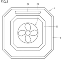
- Fig. 2 is a diagram showing an internal construction of an indoor unit 1 when indoor unit 1 of air-conditioning apparatus 100 in the first embodiment is viewed from below.
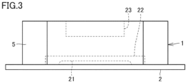
- Fig. 3 is a diagram showing the internal construction of indoor unit 1 when indoor unit 1 is viewed from a side surface side.
- a refrigerant circuit is constituted by connection of indoor unit 1 and an outdoor unit through a pipe through which refrigerant flows.
- the outdoor unit provided in an outdoor space which is the outside of a space to be air-conditioned includes, for example, a compressor, an outdoor heat exchanger, and the like, and conveys heat to the indoor unit with refrigerant through the pipe through which refrigerant flows.
- Indoor unit 1 has an indoor heat exchanger and the like, and heats or cools an indoor space by supplying, by heat exchange, heat conveyed by refrigerant to air in the indoor space which is the space to be air-conditioned.
- Fig. 1 shows indoor unit 1 characteristic in the first embodiment and does not show other apparatuses.
- indoor unit 1 is attached, for example, to a ceiling in the indoor space as the space to be air-conditioned.
- Indoor unit 1 includes, as main exterior members, a decorative panel 2 defined as a first panel, a filter panel 7 defined as a second panel, and a side panel 5 defined as a third panel.
- Indoor unit 1 includes a corner panel 6 as another exterior member.
- side panel 5 is a box-shaped panel member to surround side surfaces of indoor unit 1.
- Decorative panel 2 is a panel member in a shape of a flat plate provided around a lower opening in side panel 5.
- an air inlet 3 is provided in a central portion of decorative panel 2.
- Decorative panel 2 is provided with four air outlets 4.
- Outlet 4 is provided with a vane to adjust a direction of blow of air.
- a side where decorative panel 2 is provided is a front side and a side where side panel 5 is provided is a side surface side.
- filter panel 7 is a panel member to support a filter 9 below.
- Filter panel 7 is attached to the central portion of decorative panel 2 such that filter 9 covers air inlet 3.
- Indoor unit 1 is fixed to the ceiling in such a manner that an upper end of side panel 5 is attached to the ceiling. Indoor unit 1 may be attached to the ceiling in such a manner that a part of side panel 5 is fitted into a recess provided in the ceiling.
- a fan 23 to suction air through inlet 3 is provided in the inside of indoor unit 1.
- a drain pan 22 where drainage such as water produced as a result of heat exchange by the indoor heat exchanger is stored is provided around fan 23.
- a pipe 21 through which refrigerant as described previously flows is arranged as being partially exposed. Pipe 21 through which refrigerant flows may be hidden.
- pipe 21, drain pan 22, and fan 23 are arranged on an inner side of side panel 5.
- decorative panel 2, filter panel 7, and side panel 5 are formed from translucent members.
- Filter 9 is also formed of a translucent material.
- a member made of transparent resin or a member made of glass is employed as the translucent member.
- a member made of acrylic or polycarbonate is employed as the member made of resin. According to such a construction, in indoor unit 1, the inside can be seen through these exterior members. A person in the indoor space where indoor unit 1 is provided can thus readily visually check a sanitation state such as contamination in the inside of indoor unit 1 from the outside of indoor unit 1, for example, from a lower surface side and the side surface side of indoor unit 1.
- a state of an internal structure such as pipe 21, drain pan 22, and fan 23 arranged as shown in Fig. 2 can readily visually be checked through decorative panel 2 and filter panel 7 formed from the translucent members.
- a state of the internal structure such as pipe 21, drain pan 22, and fan 23 arranged as shown with a dashed line in Fig. 3 can readily visually be checked through side panel 5 formed from the translucent member.
- Pipe 21, drain pan 22, and fan 23 shown in Figs. 2 and 3 are formed from the translucent members.
- a member made of transparent resin or a member made of glass is employed as the translucent member.
- a member made of acrylic or polycarbonate is employed as the member made of resin.
- At least one of decorative panel 2, filter panel 7, and side panel 5 should only be formed from the translucent member. At least one of pipe 21, drain pan 22, and fan 23 should only be formed from the translucent member. In order to more readily visually check the sanitation state such as contamination in the inside of indoor unit 1, the translucent member is preferably used for more constituent elements.
- the first embodiment can obtain also an effect as follows.
- indoor unit 1 a user of and a visitor to the space where indoor unit 1 is provided can readily check the sanitation state of the inside of indoor unit 1, and hence a level of sanitation management by an owner of the space where indoor unit 1 is provided can be estimated.
- the user of and the visitor to the space where indoor unit 1 is provided are able to estimate the sanitation management level, provision of indoor unit 1 even with some cost being spent can be a value newly offered by the owner of the space who desires to appeal the high level of sanitation management.
- indoor unit 1 Since the state of the internal structure of indoor unit 1 can readily visually be checked, the internal state of indoor unit 1 including a drive component such as fan 23, a mechanical component such as pipe 21 through which refrigerant passes, and refrigerant itself which cannot be seen by a general person in a conventional indoor unit can be provided as an object to be viewed. Indoor unit 1 can thus allow a person to see and enjoy such an apparatus as an indoor unit to which attention has conventionally had to be paid not to interfere design.
- a configuration for making determination as to necessity of maintenance of indoor unit 1 in an air-conditioning system including indoor unit 1 including the translucent member as shown in the first embodiment will be described in a second embodiment.
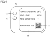
- Fig. 4 is a front view of a control panel apparatus 10 included in an air-conditioning system 500 in the second embodiment.
- Control panel apparatus 10 is an operation apparatus in a form of a panel on which a control setting value such as temperature setting, a wind level, and a wind direction in connection with indoor unit 1 can be controlled, and includes an operation portion 17 formed from an operation button and the like and a display 11 formed from a liquid crystal display.
- display 11 On display 11, other than the setting values of the temperature setting, the wind level, and the wind direction, a number of an indoor unit ("indoor unit 002" in the figure) to be operated and a two-dimensional code 12 are shown.
- Two-dimensional code 12 shows information for identifying a type of indoor unit 1 such as a model of indoor unit 1.
- Indoor unit 1 to be operated can be selected by performing an operation onto operation portion 17 on control panel apparatus 10.
- indoor unit 1 to be operated can be changed by performing an operation onto operation portion 17, and the number of the selected indoor unit and two-dimensional code 12 corresponding to the selected indoor unit are shown on display 11.
- Two-dimensional code 12 is a code to show information for connection to a web site provided by a server (a server 14 in Fig. 6 ) to make determination as to necessity of maintenance of indoor unit 1.
- Two-dimensional code 12 corresponding to indoor unit 1 may be shown on a surface of indoor unit 1 or shown by being printed on a paper medium and attached to indoor unit 1 or an area therearound.
- FIG. 5 is a diagram showing a construction of air-conditioning system 500 in the second embodiment.
- air-conditioning system 500 includes indoor unit 1 of air-conditioning apparatus 100 shown in the first embodiment, control panel apparatus 10 shown in Fig. 4 , a portable terminal 13, and server 14.
- Portable terminal 13 performs an image pick-up function to pick up an image with a camera and a communication function to communicate data through wireless communication.
- a person such as a manager of air-conditioning system 500 can use portable terminal 13 to pick up an image of indoor unit 1 and two-dimensional code 12 shown on display 11 of control panel apparatus 10 and to transmit data obtained by image pick-up to server 14.
- Fig. 6 is a block diagram showing a configuration of portable terminal 13 and server 14 in the second embodiment.
- portable terminal 13 includes a processor 131, a memory 132, a display 133, an image pick-up unit 134, and a communication unit 135.
- Memory 132 includes a read only memory (ROM) and a random access memory (RAM).
- Processor 131 develops a program stored in the ROM on the RAM or the like and executes the program.
- the program stored in the ROM is a program where a processing procedure in control of portable terminal 13 is described.
- Processor 131 carries out various types of control in portable terminal 13 in accordance with such a program.
- Portable terminal 13 is a terminal dedicated for air-conditioning system 500 and includes processor 131, memory 132, display 133, image pick-up unit 134, and communication unit 135. Display 133 also serves as an operation portion composed of a touch panel.
- Portable terminal 13 may be implemented by a general-purpose portable terminal, and in that case, a program to be executed in the dedicated terminal should be installed as an application program.
- Server 14 includes a processor 141, a memory 142, a communication unit 143, an external storage 144, and a data input device 145.
- Memory 142 includes a ROM and a RAM.
- External storage 144 is implemented by a non-volatile external storage such as a hard disk and a flash memory.
- Processor 141 develops a program stored in the ROM on the RAM or the like and executes the program.
- Processor 141 develops a program stored in external storage 144 on the RAM or the like and executes the program.
- the programs stored in the ROM and external storage 144 are each a program where a processing procedure in various types of information processing executable by server 14 is described.
- Processor 141 performs various types of information processing in accordance with such a program and communicates information through communication unit 143, reads data stored in external storage 144, and writes data into external storage 144.
- Data input device 145 is implemented by a device through which data can be inputted, such as a keyboard. Data inputted through data input device 145 may temporarily be stored in the RAM of memory 142 and used in a program executed by processor 141. The data may also temporarily be stored in the RAM of memory 142 and thereafter stored in external storage 144.
- Portable terminal 13 and server 14 can wirelessly communicate data between communication unit 135 and communication unit 143, and for example, data is transmitted from portable terminal 13 to server 14.
- FIG. 7 is a flowchart showing a flow of processing in the system when whether or not maintenance of indoor unit 1 is necessary is checked in air-conditioning system 500.
- step S1 When a manager of air-conditioning system 500 desires to check whether or not maintenance of indoor unit 1 is necessary, in step S1, the manager selects indoor unit 1 necessity of maintenance of which is to be checked, by performing an operation onto operation portion 17 of control panel apparatus 10.
- step S1 when there are a plurality of indoor units 1 to be operated through control panel apparatus 10, one of the plurality of indoor units 1 is selected, and when there is a single indoor unit 1 to be operated through control panel apparatus 10, that single indoor unit 1 is selected.
- control panel apparatus 10 shows on display 11, two-dimensional code 12 corresponding to indoor unit 1 selected in step S1.
- the manager uses portable terminal 13 to pick up an image of two-dimensional code 12 shown on display 11 of control panel apparatus 10 with the use of image pick-up unit 134.
- step S4 portable terminal 13 reads information on two-dimensional code 12 obtained by image pick-up in step S3 based on processing performed by processor 131, and it is connected via wireless communication to server 14 through communication unit 135 by access to an address on a web site for determination as to necessity of maintenance shown by two-dimensional code 12.
- server 14 Such a web site for determination as to necessity of maintenance is provided as processor 141 in server 14 performs processing for providing the web site for determination as to necessity of maintenance.
- Two-dimensional code 12 shown on display 11 of control panel apparatus 10 is information for access to the web site for determination as to necessity of maintenance as described previously.
- Server 14 provides the web site for determination as to necessity of maintenance at an address different for each model of indoor unit 1.
- Information on two-dimensional code 12 shown on display 11 of control panel apparatus 10 is thus different for each type of the indoor unit necessity of maintenance of which is to be checked.
- the web site for determination as to necessity of maintenance may be provided for each model or for each group of models each including a plurality of models similar in structure.
- step S5 the manager operates display 133 also serving as the operation portion of portable terminal 13 to start up a management program stored in memory 132 for management of maintenance.
- Processor 131 may perform processing for automatically starting up the management program when it accesses the address of the web site for determination as to necessity of maintenance.
- step S6 the manager uses image pick-up unit 134 of portable terminal 13 to pick up an image of indoor unit 1 selected in step S1.
- Image data of indoor unit 1 is thus stored in memory 132. Since the inside of indoor unit 1 can be seen through as described previously, the image picked up by portable terminal 13 shows the state on the outside and in the inside of indoor unit 1.
- step S7 the manager performs an operation onto portable terminal 13 in accordance with a request shown on display 133 of portable terminal 13 while the management program is running to transmit data required for checking as to necessity of maintenance such as the image data obtained by image pick-up from communication unit 135 to server 14.
- Data transmitted in step S7 includes not only the image data but also data indicating the owner of indoor unit 1, data indicating a model name of indoor unit 1, and data indicating timing of image pick-up.
- the data transmitted in step S7 includes not only such data but also data indicating position information such as an address of a location of image pick-up.
- Server 14 receives at communication unit 143, the data transmitted from portable terminal 13.
- processor 141 in server 14 inputs the image data received from portable terminal 13 into a trained model for making inference as to necessity of maintenance of indoor unit 1 based on the image data of indoor unit 1 to make determination as to necessity of maintenance of indoor unit 1.
- Fig. 8 is a block diagram showing a configuration used for making determination as to necessity of maintenance of indoor unit 1 in server 14.
- Server 14 includes, as the configuration to be used for determination as to necessity of maintenance of indoor unit 1, a training device 101, a trained model storage 301, and an inference device 201.
- Training device 101, inference device 201, and trained model storage 301 are implemented by software stored in memory 142 or external storage 144 and executed by processor 141.
- Training device 101 generates a trained model and has the trained model stored in trained model storage 301.
- Inference device 201 uses the trained model stored in trained model storage 301 to infer whether or not maintenance of indoor unit 1 is necessary.
- Fig. 9 is a diagram showing a configuration of training device 101.
- Training device 101 includes a data obtaining unit 102 and a model generator 103.
- Training device 101 is implemented by software stored in memory 142 or external storage 144 and executed by processor 141.
- Data obtaining unit 102 obtains training data obtained by bringing image data of indoor unit 1 stored in external storage 144 in correspondence with data indicating whether or not maintenance is necessary (ground truth). Predetermined training data is stored as the training data in external storage 144.
- the training data is image data of indoor unit 1 and it is obtained by bringing a plurality image data sets different in sanitation state such as a degree of contamination in correspondence with the data indicating whether or not maintenance is necessary (ground truth) in connection with each of image data sets.
- Predetermined data may be employed as the training data, or data added and updated by successive inputs as to whether or not maintenance is necessary (ground truth) from data input device 145 in connection with the image data of indoor unit 1 received from portable terminal 13 may be employed as the training data.
- Model generator 103 generates a trained model to infer whether or not maintenance of indoor unit 1 is necessary, based on training data obtained by associating the image data of indoor unit 1 obtained by data obtaining unit 102 and whether or not maintenance is necessary (ground truth) with each other.
- a known algorithm such as supervised learning, unsupervised learning, or reinforced learning can be employed as a training algorithm to be used by model generator 103.
- a training algorithm to which a neural network is applied will be described below.
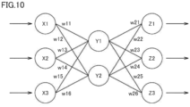
- Fig. 10 is a diagram showing a configuration of a neural network.
- Model generator 103 learns whether or not maintenance of indoor unit 1 is necessary, for example, in accordance with a neural network model by what is called supervised learning.
- Supervised learning refers to such a technique to give a set of training data including inputs and results (labels) to training device 101 to learn characteristics in the training data and to infer the results from the inputs.
- the neural network is composed of an input layer composed of a plurality of neurons, an intermediate layer (a hidden layer) composed of a plurality of neurons, and an output layer composed of a plurality of neurons.
- the intermediate layer may be composed of a single layer or at least two layers.
- the neural network generates a trained model for inference as to whether or not maintenance of indoor unit 1 is necessary, based on the image data of indoor unit 1 received from portable terminal 13 in air-conditioning system 500, in accordance with the training data obtained by data obtaining unit 102 by supervised learning.
- the neural network is trained by adjustment of weights W1 and W2 such that results outputted from the output layer as a result of input of the image data of indoor unit 1 into the input layer are close to whether or not maintenance of indoor unit 1 is necessary (ground truth).
- Model generator 103 generates and outputs the trained model by being trained as set forth above.
- the trained model outputted from model generator 103 is stored in trained model storage 301.
- Fig. 11 is a flowchart showing a procedure of training by training device 101.
- step b 1 data obtaining unit 102 obtains, for example, the image data of indoor unit 1 stored in external storage 144 and data indicating whether or not maintenance of indoor unit 1 is necessary (ground truth).
- model generator 103 generates a trained model for inference as to necessity of maintenance of indoor unit 1 from the image data of indoor unit 1 based on the training data obtained by associating the image data of indoor unit 1 obtained by data obtaining unit 102 and whether or not maintenance is necessary (ground truth) with each other.
- step b3 the trained model generated by model generator 103 is stored in trained model storage 301.
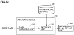
- Fig. 12 is a diagram showing a configuration of inference device 201.
- Inference device 201 includes a data obtaining unit 202 and an inference unit 203. Information on whether or not maintenance is necessary inferred by inference device 201 is used for setting up a maintenance plan in a maintenance plan set-up unit 600.
- Inference device 201 and maintenance plan set-up unit 600 are implemented by software stored in memory 142 or external storage 144 and executed by processor 141.
- Data obtaining unit 202 obtains the image data of indoor unit 1 received from portable terminal 13 of air-conditioning system 500.
- Inference unit 203 uses the trained model stored in trained model storage 301 to infer whether or not maintenance of indoor unit 1 is necessary based on the image data of indoor unit 1 received from portable terminal 13 of air-conditioning system 500 obtained by data obtaining unit 202. Inference unit 203 can output to maintenance plan set-up unit 600, data indicating whether or not maintenance of indoor unit 1 is necessary that is inferred based on the image data of indoor unit 1, by inputting the image data of indoor unit 1 obtained by data obtaining unit 202 into the trained model.
- Fig. 13 is a flowchart showing a procedure of inference by inference device 201 and a procedure of set-up of a maintenance plan by maintenance plan set-up unit 600.
- step c1 data obtaining unit 202 obtains the image data of indoor unit 1 received from portable terminal 13 of air-conditioning system 500.
- step c2 inference unit 203 inputs the image data of indoor unit 1 obtained in step c1 into the trained model stored in trained model storage 301.
- step c3 inference unit 203 infers, with the use of the trained model, whether or not maintenance of indoor unit 1 is necessary, based on the image data of indoor unit 1 obtained in step c1.
- step c3 as inference as to necessity of maintenance, a location to be maintained and contents of maintenance works such as whether or not filter 9 should be cleaned, whether or not filter 9 should be replaced, whether or not drain pan 22 should be cleaned, whether or not the inside of the panel (decorative panel 2, filter panel 7, and/or side panel 5) should be cleaned, and whether or not the panel (decorative panel 2, filter panel 7, and/or side panel 5) should be replaced are estimated by inference.
- timing of maintenance such as whether or not maintenance is necessary immediately or at which timing in the future maintenance will be necessary is estimated by inference.
- step c4 maintenance plan set-up unit 600 determines whether or not maintenance is necessary immediately based on a result of inference as to necessity of maintenance by inference unit 203 in step c3.
- step c4 When it is determined in step c4 that maintenance is necessary immediately, in step c5, maintenance plan set-up unit 600 determines to send a maintenance worker to the location where air-conditioning system 500 including indoor unit 1 determined as requiring maintenance is located and the process proceeds to step c7.
- contents of maintenance works estimated in step c3 are further determined as contents of works by the sent worker.
- step c6 When it is determined in step c4 that maintenance is not necessary immediately, in step c6, maintenance plan set-up unit 600 determines timing in the future to do maintenance, and the process proceeds to step c7. For example, in step c6, timing of maintenance estimated in step c3 such as at which timing in the future maintenance will be necessary is determined as the timing to do maintenance in the future.
- step c7 maintenance plan set-up unit 600 sets up a maintenance schedule based on matters determined in step c5 or matters determined in step c6.
- step c7 for example, when it is determined in step c5 to send a maintenance worker, a maintenance schedule as to how many workers should be sent and how long working hours are scheduled is set up based on the determined contents of maintenance works.
- step c7 for example, when timing to do maintenance in the future is determined in step c6, a maintenance schedule in accordance with the timing to do maintenance in the future is set up, for example, by securing the timing to do maintenance in the future or by notifying the owner of air-conditioning system 500 of the timing to do maintenance in the future.
- Information on the maintenance schedule thus set up is transmitted to a maintenance service provider.
- the maintenance service provider may obtain information on the maintenance schedule thus set up, by establishing connection for communication to server 14. Such a maintenance service provider can check such information on the maintenance schedule and do maintenance.
- the image data of indoor unit 1 received from portable terminal 13 is such image data as allowing checking of a state in the inside of indoor unit 1, and inference unit 203 inputs the image data of indoor unit 1 received from portable terminal 13 into the trained model to make inference as to necessity of maintenance of indoor unit 1 based on the image data of indoor unit 1 with the use of the trained model to thereby make determination as to necessity of maintenance of indoor unit 1. Therefore, the sanitation state of indoor unit 1 can readily be checked.
- determination as to necessity of maintenance based on image data can be optimized.
- a frequency of maintenance and arrangement of a schedule to send maintenance in connection with the maintenance can be optimized. By optimizing the frequency of maintenance and arrangement of the schedule to send maintenance, unnecessary maintenance can be reduced, cost for maintenance born by the owner of air-conditioning system 500 and the maintenance service provider can be reduced, and competitiveness in terms of maintenance cost in the maintenance service provider can be improved.
- Indoor unit 1 includes decorative panel 2 as the first panel provided in the front surface where air outlet 4 is provided in indoor unit 1, filter panel 7 as the second panel to which filter 9 for air inlet 3 is attached, filter panel 7 being provided in the front surface of indoor unit 1, and side panel 5 as the third panel provided in the side surface of indoor unit 1. At least one of decorative panel 2, filter panel 7, and side panel 5 is formed from a translucent member.
- the inside of indoor unit 1 can be seen through these exterior members.
- a person in the indoor space where indoor unit 1 is provided can thus readily visually check a sanitation state such as contamination in the inside of indoor unit 1 from the outside of indoor unit 1 from the lower surface side and the side surface side of indoor unit 1.
- indoor unit 1 further includes drain pan 22, pipe 21 through which refrigerant flows, and fan 23. At least one of drain pan 22, pipe 21, and fan 23 is formed from the translucent member. According to such a construction, the inside of the internal structure itself such as the inside of pipe 21, a reservoir in drain pan 22, and a front surface and a rear surface of fan 23 can also be seen through. According to such a construction, a person in the indoor space where indoor unit 1 is provided can thus readily visually check a sanitation state such as contamination in the inside of pipe 21, drain pan 22, and fan 23.
- the present disclosure includes indoor unit 1 including such translucent members as decorative panel 2, filter panel 7, and side panel 5, the inside of which can be seen through the translucent members, control panel apparatus 10 as the display apparatus to show two-dimensional code 12 corresponding to indoor unit 1, portable terminal 13 as the terminal to pick up an image of two-dimensional code 12 shown on control panel apparatus 10, to pick up an image of the inside from the outside of indoor unit 1, and to transmit image data obtained as a result of image pick-up, and server 14 to make determination as to maintenance of indoor unit 1 based on the image data transmitted from portable terminal 13.
- Portable terminal 13 can communicate with server 14 based on two-dimensional code 12 the image of which has been picked up (step S4).
- Server 14 inputs the image data received from indoor unit 1 into a trained model for inference as to necessity of maintenance of indoor unit 1 based on the image data of the portable terminal 13 to make determination as to necessity of maintenance of the indoor unit (steps c2 and c3).
- the image data of indoor unit 1 received from portable terminal 13 is such image data as allowing checking of the state of the inside of indoor unit 1
- inference unit 203 inputs the image data of indoor unit 1 received from portable terminal 13 into the trained model to make inference as to necessity of maintenance of indoor unit 1 based on the image data of indoor unit 1 with the use of the trained model.
- the server thus makes determination as to necessity of maintenance of indoor unit 1. Therefore, the sanitation state of indoor unit 1 can readily be checked.
- server 14 estimates a location to be maintained in inference as to necessity of maintenance of indoor unit 1 (step c3).
- the location to be maintained can readily be estimated based on the image data of indoor unit 1 received from portable terminal 13.
- server 14 further estimates timing when maintenance is necessary based on the estimated location of maintenance in the inference as to necessity of maintenance of indoor unit 1, and makes determination as to necessity of maintenance in accordance with the estimated timing of maintenance (step c3).
- timing when maintenance is necessary can readily be estimated based on the image data of indoor unit 1 received from portable terminal 13.
- server 14 determines contents of maintenance works for indoor unit 1 in accordance with the state of contamination of indoor unit 1 (step c3).
- contents of maintenance works for indoor unit 1 can readily be determined based on the image data of indoor unit 1 received from portable terminal 13.
- server 14 determines timing of maintenance in the future which will be necessary in indoor unit 1 based on the estimated timing of maintenance (step c6). According to such a configuration, timing of maintenance in the future which will be necessary in indoor unit 1 can readily be determined based on the image data of indoor unit 1 received from portable terminal 13.
Landscapes
- Engineering & Computer Science (AREA)
- Chemical & Material Sciences (AREA)
- Combustion & Propulsion (AREA)
- Mechanical Engineering (AREA)
- General Engineering & Computer Science (AREA)
- Human Computer Interaction (AREA)
- Physics & Mathematics (AREA)
- Fuzzy Systems (AREA)
- Mathematical Physics (AREA)
- Signal Processing (AREA)
- Air Conditioning Control Device (AREA)
- Air Filters, Heat-Exchange Apparatuses, And Housings Of Air-Conditioning Units (AREA)
- Devices For Blowing Cold Air, Devices For Blowing Warm Air, And Means For Preventing Water Condensation In Air Conditioning Units (AREA)
Abstract
Description
- The present disclosure relates to an air-conditioning apparatus and an air-conditioning system.
- Design of exterior structures such as various panels in an indoor unit included in a conventional air-conditioning apparatus may be recognized as detriment to design of a structure in an indoor space where the indoor unit is provided. In order to avoid such detriment to the design, the indoor unit may be designed to blend with the design of the indoor space where the indoor unit is provided. In addition, in order to avoid such detriment to the design, the indoor unit may be designed or provided such that the structure is hidden.
- The following is available as an air-conditioning system in consideration of an effect in a design aspect.
PTL 1 describes an air-conditioner indoor unit for hanging on a wall provided with a front panel provided on the front of an indoor unit main body and a design cover which comprises a transparent member and which is attached so as to cover the front panel from the front. A pearl paint is coated on a back surface of the design cover and a background color paint is further coated over the pearl paint. -
PTL 2 describes a construction to produce an effect of an air-conditioner as interiors at a location where it is provided, by showing an object different from the air-conditioner on a surface of a cover to cover the air-conditioner. -
- PTL 1:
WO2017/033257 - PTL 2:
Japanese Patent Laying-Open No. H11-37495 - In recent years, consciousness about sanitation tends to socially increase for various reasons such as measures against infections. In a conventional air-conditioning system, however, a sanitation state including a contamination state in the inside cannot be checked unless a panel of an indoor unit is removed, and a user has been unable to easily check the sanitation state such as the contamination state of the indoor unit.
- An air-conditioning apparatus and an air-conditioning system in the present disclosure solve the problem above, and an object thereof is to allow easy checking of a sanitation state of an indoor unit.
- An air-conditioning apparatus in the present disclosure relates to an air-conditioning apparatus including an indoor unit. The indoor unit includes a first panel provided in a front surface of the indoor unit, an air outlet being provided in the front surface, a second panel provided in the front surface of the indoor unit, a filter for an air inlet being attached to the second panel, and a third panel provided in a side surface of the indoor unit. At least one of the first panel, the second panel, and the third panel is formed from a translucent member.
- An air-conditioning system in the present disclosure includes an indoor unit including a translucent member, the inside of which can be seen through the translucent member, a display apparatus to show two-dimensional code information corresponding to the indoor unit, a terminal to pick up an image of the two-dimensional code information shown on the display apparatus, to pick up an image of the inside from the outside of the indoor unit, and to transmit image data obtained as a result of image pick-up, and a server to make determination as to maintenance of the indoor unit based on the image data transmitted from the terminal. The terminal communicates with the server based on the two-dimensional code information obtained by image pick-up. The server inputs the image data received from the indoor unit to a trained model for inference as to necessity of maintenance of the indoor unit based on the image data of the terminal to make determination as to necessity of maintenance of the indoor unit.
- According to the air-conditioning apparatus and the air-conditioning system in the present disclosure, a sanitation state of an indoor unit can readily be checked.
-
-
Fig. 1 is a perspective view of an air-conditioning apparatus 100 in a first embodiment. -
Fig. 2 is a diagram showing an internal construction of anindoor unit 1 whenindoor unit 1 of air-conditioning apparatus 100 in the first embodiment is viewed from below. -
Fig. 3 is a diagram showing the internal construction ofindoor unit 1 whenindoor unit 1 is viewed from a side surface side. -
Fig. 4 is a front view of acontrol panel apparatus 10 included in an air-conditioning system 500 in a second embodiment. -
Fig. 5 is a diagram showing a construction of an air-conditioning system 500 in the second embodiment. -
Fig. 6 is a block diagram showing a configuration of aportable terminal 13 and aserver 14 in the second embodiment. -
Fig. 7 is a flowchart showing a flow of processing in the system when whether or not maintenance ofindoor unit 1 is necessary is checked in air-conditioning system 500. -
Fig. 8 is a block diagram showing a configuration used for making determination as to necessity of maintenance ofindoor unit 1 inserver 14. -
Fig. 9 is a diagram showing a configuration of atraining device 101. -
Fig. 10 is a diagram showing a configuration of a neural network. -
Fig. 11 is a flowchart showing a procedure of training bytraining device 101. -
Fig. 12 is a diagram showing a configuration of aninference device 201. -
Fig. 13 is a flowchart showing a procedure of inference byinference device 201 and a procedure of set-up of a maintenance plan by a maintenance plan set-up unit 600. - An embodiment of the present disclosure will be described in detail below with reference to the drawings. Though a plurality of embodiments will be described below, combination of features described in the embodiments as appropriate is originally intended. The same or corresponding elements in the drawings have the same reference characters allotted and description thereof will not be repeated.
-
Fig. 1 is a perspective view of an air-conditioning apparatus 100 in a first embodiment.Fig. 2 is a diagram showing an internal construction of anindoor unit 1 whenindoor unit 1 of air-conditioning apparatus 100 in the first embodiment is viewed from below.Fig. 3 is a diagram showing the internal construction ofindoor unit 1 whenindoor unit 1 is viewed from a side surface side. - Overview of the construction of air-
conditioning apparatus 100 will initially be described. In air-conditioning apparatus 100 in the present embodiment, a refrigerant circuit is constituted by connection ofindoor unit 1 and an outdoor unit through a pipe through which refrigerant flows. The outdoor unit provided in an outdoor space which is the outside of a space to be air-conditioned includes, for example, a compressor, an outdoor heat exchanger, and the like, and conveys heat to the indoor unit with refrigerant through the pipe through which refrigerant flows.Indoor unit 1 has an indoor heat exchanger and the like, and heats or cools an indoor space by supplying, by heat exchange, heat conveyed by refrigerant to air in the indoor space which is the space to be air-conditioned. Among apparatuses that constitute air-conditioning apparatus 100,Fig. 1 showsindoor unit 1 characteristic in the first embodiment and does not show other apparatuses. - Referring to
Fig. 1 , for example,indoor unit 1 is attached, for example, to a ceiling in the indoor space as the space to be air-conditioned.Indoor unit 1 includes, as main exterior members, adecorative panel 2 defined as a first panel, afilter panel 7 defined as a second panel, and aside panel 5 defined as a third panel.Indoor unit 1 includes acorner panel 6 as another exterior member. - Referring to
Fig. 1 ,side panel 5 is a box-shaped panel member to surround side surfaces ofindoor unit 1.Decorative panel 2 is a panel member in a shape of a flat plate provided around a lower opening inside panel 5. In a central portion ofdecorative panel 2, anair inlet 3 is provided.Decorative panel 2 is provided with fourair outlets 4.Outlet 4 is provided with a vane to adjust a direction of blow of air. Inindoor unit 1, a side wheredecorative panel 2 is provided is a front side and a side whereside panel 5 is provided is a side surface side. - As shown in
Fig. 1 ,filter panel 7 is a panel member to support afilter 9 below.Filter panel 7 is attached to the central portion ofdecorative panel 2 such thatfilter 9 coversair inlet 3. -
Indoor unit 1 is fixed to the ceiling in such a manner that an upper end ofside panel 5 is attached to the ceiling.Indoor unit 1 may be attached to the ceiling in such a manner that a part ofside panel 5 is fitted into a recess provided in the ceiling. - As shown in
Fig. 2 , afan 23 to suction air throughinlet 3 is provided in the inside ofindoor unit 1. In the inside ofindoor unit 1, adrain pan 22 where drainage such as water produced as a result of heat exchange by the indoor heat exchanger is stored is provided aroundfan 23. In the inside ofindoor unit 1, apipe 21 through which refrigerant as described previously flows is arranged as being partially exposed.Pipe 21 through which refrigerant flows may be hidden. - As shown in
Fig. 3 , inindoor unit 1,pipe 21,drain pan 22, andfan 23 are arranged on an inner side ofside panel 5. - Among members to constitute
indoor unit 1 described above,decorative panel 2,filter panel 7, andside panel 5 are formed from translucent members.Filter 9 is also formed of a translucent material. For example, a member made of transparent resin or a member made of glass is employed as the translucent member. A member made of acrylic or polycarbonate is employed as the member made of resin. According to such a construction, inindoor unit 1, the inside can be seen through these exterior members. A person in the indoor space whereindoor unit 1 is provided can thus readily visually check a sanitation state such as contamination in the inside ofindoor unit 1 from the outside ofindoor unit 1, for example, from a lower surface side and the side surface side ofindoor unit 1. - For example, from the lower surface side of
indoor unit 1, a state of an internal structure such aspipe 21,drain pan 22, andfan 23 arranged as shown inFig. 2 can readily visually be checked throughdecorative panel 2 and filterpanel 7 formed from the translucent members. From the side surface side ofindoor unit 1, a state of the internal structure such aspipe 21,drain pan 22, andfan 23 arranged as shown with a dashed line inFig. 3 can readily visually be checked throughside panel 5 formed from the translucent member. -
Pipe 21,drain pan 22, andfan 23 shown inFigs. 2 and3 are formed from the translucent members. For example, a member made of transparent resin or a member made of glass is employed as the translucent member. A member made of acrylic or polycarbonate is employed as the member made of resin. According to such a construction, inindoor unit 1, the inside of the internal structure itself such as the inside ofpipe 21, a reservoir indrain pan 22, and a front surface and a rear surface offan 23 can also be seen through. A person in the indoor space whereindoor unit 1 is provided can thus readily visually check the sanitation state such as contamination in the inside ofpipe 21,drain pan 22, andfan 23. - At least one of
decorative panel 2,filter panel 7, andside panel 5 should only be formed from the translucent member. At least one ofpipe 21,drain pan 22, andfan 23 should only be formed from the translucent member. In order to more readily visually check the sanitation state such as contamination in the inside ofindoor unit 1, the translucent member is preferably used for more constituent elements. - The first embodiment can obtain also an effect as follows. In
indoor unit 1, a user of and a visitor to the space whereindoor unit 1 is provided can readily check the sanitation state of the inside ofindoor unit 1, and hence a level of sanitation management by an owner of the space whereindoor unit 1 is provided can be estimated. When the user of and the visitor to the space whereindoor unit 1 is provided are able to estimate the sanitation management level, provision ofindoor unit 1 even with some cost being spent can be a value newly offered by the owner of the space who desires to appeal the high level of sanitation management. - Since the state of the internal structure of
indoor unit 1 can readily visually be checked, the internal state ofindoor unit 1 including a drive component such asfan 23, a mechanical component such aspipe 21 through which refrigerant passes, and refrigerant itself which cannot be seen by a general person in a conventional indoor unit can be provided as an object to be viewed.Indoor unit 1 can thus allow a person to see and enjoy such an apparatus as an indoor unit to which attention has conventionally had to be paid not to interfere design. - Since the state of the internal structure of
indoor unit 1 can readily visually be checked, clogging offilter 9 can be avoided, and reduction in power consumption and suppression of lowering in efficiency of heat exchange offan 23 owing to reduction in increase in air passage resistance can be achieved to thereby reduce power consumption. Since the state of the internal structure ofindoor unit 1 can readily visually be checked, leakage of drainage fromdrain pan 22 or the like, emergence of bacteria, risk of infection by viruses or bacteria, and generation of odors can be avoided. The state of the internal structure ofindoor unit 1 can readily visually be checked. - A configuration for making determination as to necessity of maintenance of
indoor unit 1 in an air-conditioning system includingindoor unit 1 including the translucent member as shown in the first embodiment will be described in a second embodiment. -
Fig. 4 is a front view of acontrol panel apparatus 10 included in an air-conditioning system 500 in the second embodiment.Control panel apparatus 10 is an operation apparatus in a form of a panel on which a control setting value such as temperature setting, a wind level, and a wind direction in connection withindoor unit 1 can be controlled, and includes anoperation portion 17 formed from an operation button and the like and adisplay 11 formed from a liquid crystal display. Ondisplay 11, other than the setting values of the temperature setting, the wind level, and the wind direction, a number of an indoor unit ("indoor unit 002" in the figure) to be operated and a two-dimensional code 12 are shown. Two-dimensional code 12 shows information for identifying a type ofindoor unit 1 such as a model ofindoor unit 1. -
Indoor unit 1 to be operated can be selected by performing an operation ontooperation portion 17 oncontrol panel apparatus 10. When a plurality ofindoor units 1 are provided indoors,indoor unit 1 to be operated can be changed by performing an operation ontooperation portion 17, and the number of the selected indoor unit and two-dimensional code 12 corresponding to the selected indoor unit are shown ondisplay 11. Two-dimensional code 12 is a code to show information for connection to a web site provided by a server (aserver 14 inFig. 6 ) to make determination as to necessity of maintenance ofindoor unit 1. Two-dimensional code 12 corresponding toindoor unit 1 may be shown on a surface ofindoor unit 1 or shown by being printed on a paper medium and attached toindoor unit 1 or an area therearound. -
Fig. 5 is a diagram showing a construction of air-conditioning system 500 in the second embodiment. Referring toFig. 5 , air-conditioning system 500 includesindoor unit 1 of air-conditioning apparatus 100 shown in the first embodiment,control panel apparatus 10 shown inFig. 4 , aportable terminal 13, andserver 14.Portable terminal 13 performs an image pick-up function to pick up an image with a camera and a communication function to communicate data through wireless communication. A person such as a manager of air-conditioning system 500 can useportable terminal 13 to pick up an image ofindoor unit 1 and two-dimensional code 12 shown ondisplay 11 ofcontrol panel apparatus 10 and to transmit data obtained by image pick-up toserver 14. -
Fig. 6 is a block diagram showing a configuration ofportable terminal 13 andserver 14 in the second embodiment. Referring toFig. 6 ,portable terminal 13 includes aprocessor 131, amemory 132, adisplay 133, an image pick-upunit 134, and acommunication unit 135. -
Memory 132 includes a read only memory (ROM) and a random access memory (RAM).Processor 131 develops a program stored in the ROM on the RAM or the like and executes the program. The program stored in the ROM is a program where a processing procedure in control ofportable terminal 13 is described.Processor 131 carries out various types of control inportable terminal 13 in accordance with such a program. -
Portable terminal 13 is a terminal dedicated for air-conditioning system 500 and includesprocessor 131,memory 132,display 133, image pick-upunit 134, andcommunication unit 135.Display 133 also serves as an operation portion composed of a touch panel.Portable terminal 13 may be implemented by a general-purpose portable terminal, and in that case, a program to be executed in the dedicated terminal should be installed as an application program. -
Server 14 includes aprocessor 141, amemory 142, acommunication unit 143, anexternal storage 144, and adata input device 145.Memory 142 includes a ROM and a RAM.External storage 144 is implemented by a non-volatile external storage such as a hard disk and a flash memory.Processor 141 develops a program stored in the ROM on the RAM or the like and executes the program.Processor 141 develops a program stored inexternal storage 144 on the RAM or the like and executes the program. The programs stored in the ROM andexternal storage 144 are each a program where a processing procedure in various types of information processing executable byserver 14 is described.Processor 141 performs various types of information processing in accordance with such a program and communicates information throughcommunication unit 143, reads data stored inexternal storage 144, and writes data intoexternal storage 144. -
Data input device 145 is implemented by a device through which data can be inputted, such as a keyboard. Data inputted throughdata input device 145 may temporarily be stored in the RAM ofmemory 142 and used in a program executed byprocessor 141. The data may also temporarily be stored in the RAM ofmemory 142 and thereafter stored inexternal storage 144. -
Portable terminal 13 andserver 14 can wirelessly communicate data betweencommunication unit 135 andcommunication unit 143, and for example, data is transmitted from portable terminal 13 toserver 14. - A flow of processing in the system when whether or not maintenance of
indoor unit 1 is necessary is checked in air-conditioning system 500 will now be described.Fig. 7 is a flowchart showing a flow of processing in the system when whether or not maintenance ofindoor unit 1 is necessary is checked in air-conditioning system 500. - When a manager of air-
conditioning system 500 desires to check whether or not maintenance ofindoor unit 1 is necessary, in step S1, the manager selectsindoor unit 1 necessity of maintenance of which is to be checked, by performing an operation ontooperation portion 17 ofcontrol panel apparatus 10. In step S1, when there are a plurality ofindoor units 1 to be operated throughcontrol panel apparatus 10, one of the plurality ofindoor units 1 is selected, and when there is a singleindoor unit 1 to be operated throughcontrol panel apparatus 10, that singleindoor unit 1 is selected. - In step S2,
control panel apparatus 10 shows ondisplay 11, two-dimensional code 12 corresponding toindoor unit 1 selected in step S1. In step S3, the manager usesportable terminal 13 to pick up an image of two-dimensional code 12 shown ondisplay 11 ofcontrol panel apparatus 10 with the use of image pick-upunit 134. - In step S4,
portable terminal 13 reads information on two-dimensional code 12 obtained by image pick-up in step S3 based on processing performed byprocessor 131, and it is connected via wireless communication toserver 14 throughcommunication unit 135 by access to an address on a web site for determination as to necessity of maintenance shown by two-dimensional code 12. Such a web site for determination as to necessity of maintenance is provided asprocessor 141 inserver 14 performs processing for providing the web site for determination as to necessity of maintenance. - Two-
dimensional code 12 shown ondisplay 11 ofcontrol panel apparatus 10 is information for access to the web site for determination as to necessity of maintenance as described previously.Server 14 provides the web site for determination as to necessity of maintenance at an address different for each model ofindoor unit 1. Information on two-dimensional code 12 shown ondisplay 11 ofcontrol panel apparatus 10 is thus different for each type of the indoor unit necessity of maintenance of which is to be checked. The web site for determination as to necessity of maintenance may be provided for each model or for each group of models each including a plurality of models similar in structure. - In step S5, the manager operates
display 133 also serving as the operation portion of portable terminal 13 to start up a management program stored inmemory 132 for management of maintenance.Processor 131 may perform processing for automatically starting up the management program when it accesses the address of the web site for determination as to necessity of maintenance. - In step S6, the manager uses image pick-up
unit 134 of portable terminal 13 to pick up an image ofindoor unit 1 selected in step S1. Image data ofindoor unit 1 is thus stored inmemory 132. Since the inside ofindoor unit 1 can be seen through as described previously, the image picked up byportable terminal 13 shows the state on the outside and in the inside ofindoor unit 1. - After the manager thus picks up the image of
indoor unit 1, in step S7, the manager performs an operation onto portable terminal 13 in accordance with a request shown ondisplay 133 of portable terminal 13 while the management program is running to transmit data required for checking as to necessity of maintenance such as the image data obtained by image pick-up fromcommunication unit 135 toserver 14. Data transmitted in step S7 includes not only the image data but also data indicating the owner ofindoor unit 1, data indicating a model name ofindoor unit 1, and data indicating timing of image pick-up. The data transmitted in step S7 includes not only such data but also data indicating position information such as an address of a location of image pick-up. -
Server 14 receives atcommunication unit 143, the data transmitted fromportable terminal 13. In step S8,processor 141 inserver 14 inputs the image data received from portable terminal 13 into a trained model for making inference as to necessity of maintenance ofindoor unit 1 based on the image data ofindoor unit 1 to make determination as to necessity of maintenance ofindoor unit 1. - A method of making determination as to necessity of maintenance of
indoor unit 1 inserver 14 will now be described. -
Fig. 8 is a block diagram showing a configuration used for making determination as to necessity of maintenance ofindoor unit 1 inserver 14.Server 14 includes, as the configuration to be used for determination as to necessity of maintenance ofindoor unit 1, atraining device 101, a trainedmodel storage 301, and aninference device 201.Training device 101,inference device 201, and trainedmodel storage 301 are implemented by software stored inmemory 142 orexternal storage 144 and executed byprocessor 141. -
Training device 101 generates a trained model and has the trained model stored in trainedmodel storage 301.Inference device 201 uses the trained model stored in trainedmodel storage 301 to infer whether or not maintenance ofindoor unit 1 is necessary. -
Fig. 9 is a diagram showing a configuration oftraining device 101.Training device 101 includes adata obtaining unit 102 and amodel generator 103.Training device 101 is implemented by software stored inmemory 142 orexternal storage 144 and executed byprocessor 141. -
Data obtaining unit 102 obtains training data obtained by bringing image data ofindoor unit 1 stored inexternal storage 144 in correspondence with data indicating whether or not maintenance is necessary (ground truth). Predetermined training data is stored as the training data inexternal storage 144. The training data is image data ofindoor unit 1 and it is obtained by bringing a plurality image data sets different in sanitation state such as a degree of contamination in correspondence with the data indicating whether or not maintenance is necessary (ground truth) in connection with each of image data sets. - Predetermined data may be employed as the training data, or data added and updated by successive inputs as to whether or not maintenance is necessary (ground truth) from
data input device 145 in connection with the image data ofindoor unit 1 received fromportable terminal 13 may be employed as the training data. -
Model generator 103 generates a trained model to infer whether or not maintenance ofindoor unit 1 is necessary, based on training data obtained by associating the image data ofindoor unit 1 obtained bydata obtaining unit 102 and whether or not maintenance is necessary (ground truth) with each other. - A known algorithm such as supervised learning, unsupervised learning, or reinforced learning can be employed as a training algorithm to be used by
model generator 103. By way of example, a training algorithm to which a neural network is applied will be described below. -
Fig. 10 is a diagram showing a configuration of a neural network.Model generator 103 learns whether or not maintenance ofindoor unit 1 is necessary, for example, in accordance with a neural network model by what is called supervised learning. Supervised learning refers to such a technique to give a set of training data including inputs and results (labels) totraining device 101 to learn characteristics in the training data and to infer the results from the inputs. - The neural network is composed of an input layer composed of a plurality of neurons, an intermediate layer (a hidden layer) composed of a plurality of neurons, and an output layer composed of a plurality of neurons. The intermediate layer may be composed of a single layer or at least two layers.
- For example, in a case of a neural network including three layers, when a plurality of inputs are provided to the input layer (X1 to X3), values thereof are multiplied by a weight W1 (w11 to w16) and results of the multiplication are provided to the intermediate layer (Y1 to Y2). The results are further multiplied by a weight W2 (w21 to w26) and results of the multiplication are outputted from the output layer (Z1 to Z3). Results of output vary depending on values of weights W1 and W2.
- The neural network generates a trained model for inference as to whether or not maintenance of
indoor unit 1 is necessary, based on the image data ofindoor unit 1 received from portable terminal 13 in air-conditioning system 500, in accordance with the training data obtained bydata obtaining unit 102 by supervised learning. - In other words, the neural network is trained by adjustment of weights W1 and W2 such that results outputted from the output layer as a result of input of the image data of
indoor unit 1 into the input layer are close to whether or not maintenance ofindoor unit 1 is necessary (ground truth). -
Model generator 103 generates and outputs the trained model by being trained as set forth above. - The trained model outputted from
model generator 103 is stored in trainedmodel storage 301. -
Fig. 11 is a flowchart showing a procedure of training bytraining device 101. - In
step b 1,data obtaining unit 102 obtains, for example, the image data ofindoor unit 1 stored inexternal storage 144 and data indicating whether or not maintenance ofindoor unit 1 is necessary (ground truth). - In step b2,
model generator 103 generates a trained model for inference as to necessity of maintenance ofindoor unit 1 from the image data ofindoor unit 1 based on the training data obtained by associating the image data ofindoor unit 1 obtained bydata obtaining unit 102 and whether or not maintenance is necessary (ground truth) with each other. - In step b3, the trained model generated by
model generator 103 is stored in trainedmodel storage 301. -
Fig. 12 is a diagram showing a configuration ofinference device 201.Inference device 201 includes adata obtaining unit 202 and aninference unit 203. Information on whether or not maintenance is necessary inferred byinference device 201 is used for setting up a maintenance plan in a maintenance plan set-upunit 600.Inference device 201 and maintenance plan set-upunit 600 are implemented by software stored inmemory 142 orexternal storage 144 and executed byprocessor 141. -
Data obtaining unit 202 obtains the image data ofindoor unit 1 received fromportable terminal 13 of air-conditioning system 500. -
Inference unit 203 uses the trained model stored in trainedmodel storage 301 to infer whether or not maintenance ofindoor unit 1 is necessary based on the image data ofindoor unit 1 received fromportable terminal 13 of air-conditioning system 500 obtained bydata obtaining unit 202.Inference unit 203 can output to maintenance plan set-upunit 600, data indicating whether or not maintenance ofindoor unit 1 is necessary that is inferred based on the image data ofindoor unit 1, by inputting the image data ofindoor unit 1 obtained bydata obtaining unit 202 into the trained model. -
Fig. 13 is a flowchart showing a procedure of inference byinference device 201 and a procedure of set-up of a maintenance plan by maintenance plan set-upunit 600. - In step c1,
data obtaining unit 202 obtains the image data ofindoor unit 1 received fromportable terminal 13 of air-conditioning system 500. - In step c2,
inference unit 203 inputs the image data ofindoor unit 1 obtained in step c1 into the trained model stored in trainedmodel storage 301. In step c3,inference unit 203 infers, with the use of the trained model, whether or not maintenance ofindoor unit 1 is necessary, based on the image data ofindoor unit 1 obtained in step c1. - By way of example, in step c3, as inference as to necessity of maintenance, a location to be maintained and contents of maintenance works such as whether or not filter 9 should be cleaned, whether or not filter 9 should be replaced, whether or not drain
pan 22 should be cleaned, whether or not the inside of the panel (decorative panel 2,filter panel 7, and/or side panel 5) should be cleaned, and whether or not the panel (decorative panel 2,filter panel 7, and/or side panel 5) should be replaced are estimated by inference. Depending on the state of contamination at the location estimated as the location to be maintained, timing of maintenance such as whether or not maintenance is necessary immediately or at which timing in the future maintenance will be necessary is estimated by inference. - In step c4, maintenance plan set-up
unit 600 determines whether or not maintenance is necessary immediately based on a result of inference as to necessity of maintenance byinference unit 203 in step c3. - When it is determined in step c4 that maintenance is necessary immediately, in step c5, maintenance plan set-up
unit 600 determines to send a maintenance worker to the location where air-conditioning system 500 includingindoor unit 1 determined as requiring maintenance is located and the process proceeds to step c7. When it is determined to send the maintenance worker, contents of maintenance works estimated in step c3 are further determined as contents of works by the sent worker. - When it is determined in step c4 that maintenance is not necessary immediately, in step c6, maintenance plan set-up
unit 600 determines timing in the future to do maintenance, and the process proceeds to step c7. For example, in step c6, timing of maintenance estimated in step c3 such as at which timing in the future maintenance will be necessary is determined as the timing to do maintenance in the future. - In step c7, maintenance plan set-up
unit 600 sets up a maintenance schedule based on matters determined in step c5 or matters determined in step c6. In step c7, for example, when it is determined in step c5 to send a maintenance worker, a maintenance schedule as to how many workers should be sent and how long working hours are scheduled is set up based on the determined contents of maintenance works. In step c7, for example, when timing to do maintenance in the future is determined in step c6, a maintenance schedule in accordance with the timing to do maintenance in the future is set up, for example, by securing the timing to do maintenance in the future or by notifying the owner of air-conditioning system 500 of the timing to do maintenance in the future. - Information on the maintenance schedule thus set up is transmitted to a maintenance service provider. The maintenance service provider may obtain information on the maintenance schedule thus set up, by establishing connection for communication to
server 14. Such a maintenance service provider can check such information on the maintenance schedule and do maintenance. - In the procedure of inference by
inference device 201 and the procedure for set-up of a maintenance plan by maintenance plan set-upunit 600 described above, the image data ofindoor unit 1 received fromportable terminal 13 is such image data as allowing checking of a state in the inside ofindoor unit 1, andinference unit 203 inputs the image data ofindoor unit 1 received from portable terminal 13 into the trained model to make inference as to necessity of maintenance ofindoor unit 1 based on the image data ofindoor unit 1 with the use of the trained model to thereby make determination as to necessity of maintenance ofindoor unit 1. Therefore, the sanitation state ofindoor unit 1 can readily be checked. - In the second embodiment, in addition to the effect as described previously, determination as to necessity of maintenance based on image data can be optimized. In the second embodiment, in addition to the effect as described previously, a frequency of maintenance and arrangement of a schedule to send maintenance in connection with the maintenance can be optimized. By optimizing the frequency of maintenance and arrangement of the schedule to send maintenance, unnecessary maintenance can be reduced, cost for maintenance born by the owner of air-
conditioning system 500 and the maintenance service provider can be reduced, and competitiveness in terms of maintenance cost in the maintenance service provider can be improved. - Other effects obtained by the structure of
indoor unit 1 to allow the state of the internal structure to more readily visually be checked are as follows. For example, a fault and a failure that have not conventionally been confirmed unless such exterior objects as various panels are removed, such as physical damage toindoor unit 1 or displacement of a position where a structure inindoor unit 1 is fixed, can be estimated in advance based on the image data obtained by image pick-up ofindoor unit 1. Therefore, a repair item such as "repair completed on the first visit" can be included in items of a maintenance service. - In order to avoid erroneous use of air-
conditioning system 500 by a third party who is not supposed to use air-conditioning system 500, for example, entry of a password may be requested in a stage preceding an operation to show two-dimensional code 12 or at the time of connection to a web site, and based on password authentication, only when a correct password is entered, various types of processing for determining whether or not maintenance ofindoor unit 1 in air-conditioning system 500 is necessary may be performed. -
- (1)
Training device 101 andinference device 201 may be located on a cloud server. - (2) In the second embodiment described previously, an example of application of supervised learning to the training algorithm to be used by
model generator 103 is described, however, limitation as such is not intended. Other than supervised learning, reinforced learning, unsupervised learning, or semi-supervised learning can also be applied to the training algorithm. - (3)
Model generator 103 may use training data created based on image data ofindoor units 1 of a plurality of air-conditioning systems 500 to learn whether or not maintenance ofindoor unit 1 is necessary.Model generator 103 may use training data created based on image data ofindoor units 1 of a plurality of air-conditioning systems 500 that operate in an identical area to learn whether or not maintenance ofindoor unit 1 is necessary.Model generator 103 may use training data created based on image data ofindoor units 1 of a plurality of air-conditioning systems 500 that operate independently in different areas to learn whether or not maintenance ofindoor unit 1 is necessary. - (4)
Model generator 103 can also add or remove air-conditioning system 500 to obtain training data in midway. Furthermore,training device 101 which has learned whether or not maintenance is necessary in connection with a certain air-conditioning system 500 may be applied to a training device of an air-conditioning system different from the former air-conditioning system to learn again whether or not maintenance is necessary in connection with such another air-conditioning system for update. - (5) Deep learning to learn extraction of a feature value itself can also be employed as the training algorithm where
model generator 103 is used, and machine learning may be done in accordance with other known methods such as genetic programming, functional logic programming, or a support vector machine. - (6) Though
inference device 201 makes inference as to necessity of maintenance based on the image data obtained bydata obtaining unit 202 with the use of the trained model in the embodiment, limitation as such is not intended. The inference device may make inference as to necessity of maintenance based on input data obtained by the data obtaining unit based on rule-based reasoning or case-based reasoning. - (7)
Indoor unit 1 in the embodiment may allow works for mount and removal of a panel to be more efficient by implementing a panel such as a decorative panel provided as an exterior member, as a mount unit for mounting a decorative panel inJapanese Patent No. 5950877 - The embodiments described above will be described again with reference to the drawings.
- The present disclosure relates to air-
conditioning apparatus 100 includingindoor unit 1.Indoor unit 1 includesdecorative panel 2 as the first panel provided in the front surface whereair outlet 4 is provided inindoor unit 1,filter panel 7 as the second panel to whichfilter 9 forair inlet 3 is attached,filter panel 7 being provided in the front surface ofindoor unit 1, andside panel 5 as the third panel provided in the side surface ofindoor unit 1. At least one ofdecorative panel 2,filter panel 7, andside panel 5 is formed from a translucent member. - According to such a construction, the inside of
indoor unit 1 can be seen through these exterior members. Thus, a person in the indoor space whereindoor unit 1 is provided can thus readily visually check a sanitation state such as contamination in the inside ofindoor unit 1 from the outside ofindoor unit 1 from the lower surface side and the side surface side ofindoor unit 1. - Preferably,
indoor unit 1 further includesdrain pan 22,pipe 21 through which refrigerant flows, andfan 23. At least one ofdrain pan 22,pipe 21, andfan 23 is formed from the translucent member. According to such a construction, the inside of the internal structure itself such as the inside ofpipe 21, a reservoir indrain pan 22, and a front surface and a rear surface offan 23 can also be seen through. According to such a construction, a person in the indoor space whereindoor unit 1 is provided can thus readily visually check a sanitation state such as contamination in the inside ofpipe 21,drain pan 22, andfan 23. - The present disclosure includes
indoor unit 1 including such translucent members asdecorative panel 2,filter panel 7, andside panel 5, the inside of which can be seen through the translucent members,control panel apparatus 10 as the display apparatus to show two-dimensional code 12 corresponding toindoor unit 1,portable terminal 13 as the terminal to pick up an image of two-dimensional code 12 shown oncontrol panel apparatus 10, to pick up an image of the inside from the outside ofindoor unit 1, and to transmit image data obtained as a result of image pick-up, andserver 14 to make determination as to maintenance ofindoor unit 1 based on the image data transmitted fromportable terminal 13.Portable terminal 13 can communicate withserver 14 based on two-dimensional code 12 the image of which has been picked up (step S4).Server 14 inputs the image data received fromindoor unit 1 into a trained model for inference as to necessity of maintenance ofindoor unit 1 based on the image data of theportable terminal 13 to make determination as to necessity of maintenance of the indoor unit (steps c2 and c3). - According to such a configuration, in
server 14, the image data ofindoor unit 1 received fromportable terminal 13 is such image data as allowing checking of the state of the inside ofindoor unit 1, andinference unit 203 inputs the image data ofindoor unit 1 received from portable terminal 13 into the trained model to make inference as to necessity of maintenance ofindoor unit 1 based on the image data ofindoor unit 1 with the use of the trained model. The server thus makes determination as to necessity of maintenance ofindoor unit 1. Therefore, the sanitation state ofindoor unit 1 can readily be checked. - Preferably,
server 14 estimates a location to be maintained in inference as to necessity of maintenance of indoor unit 1 (step c3). According to such a configuration, the location to be maintained can readily be estimated based on the image data ofindoor unit 1 received fromportable terminal 13. - Preferably,
server 14 further estimates timing when maintenance is necessary based on the estimated location of maintenance in the inference as to necessity of maintenance ofindoor unit 1, and makes determination as to necessity of maintenance in accordance with the estimated timing of maintenance (step c3). According to such a configuration, timing when maintenance is necessary can readily be estimated based on the image data ofindoor unit 1 received fromportable terminal 13. - Preferably, when
server 14 determines that maintenance ofindoor unit 1 is necessary, it determines contents of maintenance works forindoor unit 1 in accordance with the state of contamination of indoor unit 1 (step c3). According to such a configuration, contents of maintenance works forindoor unit 1 can readily be determined based on the image data ofindoor unit 1 received fromportable terminal 13. - Preferably, when
server 14 determines that maintenance ofindoor unit 1 is not necessary, it determines timing of maintenance in the future which will be necessary inindoor unit 1 based on the estimated timing of maintenance (step c6). According to such a configuration, timing of maintenance in the future which will be necessary inindoor unit 1 can readily be determined based on the image data ofindoor unit 1 received fromportable terminal 13. - It should be understood that the embodiments disclosed herein are illustrative and non-restrictive in every respect. The scope of the present disclosure is defined by the terms of the claims rather than the description of the embodiments above and is intended to include any modifications within the scope and meaning equivalent to the terms of the claims.
- 100 air-conditioning apparatus; 1 indoor unit; 4 outlet; 2 decorative panel; 7 filter panel; 5 side panel; 22 drain pan; 23 fan; 21 pipe; 10 control panel apparatus; 11 display; 13 portable terminal; 14 server
Claims (7)
- An air-conditioning apparatus comprising:an indoor unit, whereinthe indoor unit comprisesa first panel provided in a front surface of the indoor unit, an air outlet being provided in the front surface,a second panel provided in the front surface of the indoor unit, a filter for an air inlet being attached to the second panel, anda third panel provided in a side surface of the indoor unit, andat least one of the first panel, the second panel, and the third panel is formed from a translucent member.
- The air-conditioning apparatus according to claim 1, whereinthe indoor unit further comprisesa drain pan,a pipe through which refrigerant flows, anda fan, andat least one of the drain pan, the pipe, and the fan is formed from a translucent member.
- An air-conditioning system comprising:an indoor unit comprising a translucent member, inside of which can be seen through the translucent member;a display apparatus to show two-dimensional code information corresponding to the indoor unit;a terminal to pick up an image of the two-dimensional code information shown on the display apparatus, to pick up an image of the inside from outside of the indoor unit, and to transmit image data obtained as a result of image pick-up; anda server to make determination as to maintenance of the indoor unit based on the image data transmitted from the terminal, whereinthe terminal is permitted to transmit the image data obtained as a result of image pick-up to the server based on the two-dimensional code information obtained by image pick-up, andthe server inputs the image data received from the indoor unit to a trained model for inference as to necessity of maintenance of the indoor unit based on the image data of the terminal to make determination as to necessity of maintenance of the indoor unit.
- The air-conditioning system according to claim 3, wherein
the server estimates a location to be maintained, in the inference as to necessity of maintenance of the indoor unit. - The air-conditioning system according to claim 4, wherein
the server further estimates timing when maintenance is necessary based on the estimated location to be maintained in the inference as to necessity of maintenance of the indoor unit and makes determination as to necessity of maintenance in accordance with the estimated timing of maintenance. - The air-conditioning system according to claim 5, wherein
when the server determines that maintenance of the indoor unit is necessary, the server determines contents of works in maintenance of the indoor unit in accordance with a contamination state of the indoor unit. - The air-conditioning system according to claim 5, wherein
when the server determines that maintenance of the indoor unit is not necessary, the server determines timing of future maintenance which will be necessary for the indoor unit based on the estimated timing of maintenance.
Applications Claiming Priority (1)
| Application Number | Priority Date | Filing Date | Title |
|---|---|---|---|
| PCT/JP2021/015711 WO2022219802A1 (en) | 2021-04-16 | 2021-04-16 | Air-conditioning device and air-conditioning system |
Publications (2)
| Publication Number | Publication Date |
|---|---|
| EP4325135A1 true EP4325135A1 (en) | 2024-02-21 |
| EP4325135A4 EP4325135A4 (en) | 2024-05-01 |
Family
ID=83640287
Family Applications (1)
| Application Number | Title | Priority Date | Filing Date |
|---|---|---|---|
| EP21936996.4A Pending EP4325135A4 (en) | 2021-04-16 | 2021-04-16 | Air-conditioning device and air-conditioning system |
Country Status (4)
| Country | Link |
|---|---|
| US (1) | US20240167723A1 (en) |
| EP (1) | EP4325135A4 (en) |
| JP (1) | JP7475541B2 (en) |
| WO (1) | WO2022219802A1 (en) |
Family Cites Families (32)
| Publication number | Priority date | Publication date | Assignee | Title |
|---|---|---|---|---|
| JPS58123222U (en) * | 1982-02-15 | 1983-08-22 | 木村工機株式会社 | air conditioner |
| JPH04278127A (en) * | 1991-03-01 | 1992-10-02 | Hitachi Ltd | Air conditioner |
| JPH06307742A (en) * | 1993-04-21 | 1994-11-01 | Sanyo Electric Co Ltd | Air-conditioner |
| JP3070226U (en) * | 2000-01-12 | 2000-07-28 | 新設備工業株式会社 | Inspection window device for air conditioner |
| JP2002243254A (en) * | 2001-02-19 | 2002-08-28 | Mitsubishi Electric Corp | Air conditioning system |
| KR101197879B1 (en) * | 2008-01-25 | 2012-11-05 | 다이킨 고교 가부시키가이샤 | Indoor unit of air conditioning apparatus |
| JP5887682B2 (en) * | 2011-03-30 | 2016-03-16 | 公益財団法人若狭湾エネルギー研究センター | Heat pipe that can switch heat transport direction and heat pipe that can automatically switch heat transport direction by check valve |
| JP5494551B2 (en) * | 2011-04-15 | 2014-05-14 | ダイキン工業株式会社 | Indoor unit |
| US20130059598A1 (en) * | 2011-04-27 | 2013-03-07 | F-Matic, Inc. | Interactive computer software processes and apparatus for managing, tracking, reporting, providing feedback and tasking |
| JP5459303B2 (en) * | 2011-12-26 | 2014-04-02 | ダイキン工業株式会社 | Air conditioner |
| US8851381B2 (en) * | 2012-10-17 | 2014-10-07 | Rockwell Automation Technologies, Inc. | Motor and motor drive diagnostic system using barcode |
| WO2014149174A1 (en) * | 2013-03-15 | 2014-09-25 | Stride Tool, Inc. | Smart hvac manifold system |
| JP5950877B2 (en) | 2013-08-07 | 2016-07-13 | 三菱電機株式会社 | Air conditioner decorative panel mounting structure and indoor unit |
| US20150066782A1 (en) * | 2013-08-28 | 2015-03-05 | PragmaTech Ltd. | Computer monitoring, servicing, and management of remote equipment and assets |
| JP6398550B2 (en) * | 2014-09-30 | 2018-10-03 | 株式会社富士通ゼネラル | Embedded ceiling air conditioner |
| US20170364106A1 (en) * | 2014-12-22 | 2017-12-21 | Trane International Inc. | Systems and methods for provisioning components of an hvac system |
| CN106152331A (en) | 2015-04-07 | 2016-11-23 | 大金工业株式会社 | Indoor machine of air conditioner |
| US20180172312A1 (en) * | 2015-08-24 | 2018-06-21 | Mitsubishi Electric Corporation | Air-conditioning apparatus indoor unit |
| CN105465947B (en) * | 2015-11-24 | 2018-10-19 | 珠海格力电器股份有限公司 | Air conditioner fault processing method, device and system |
| JP6743383B2 (en) * | 2015-12-18 | 2020-08-19 | ダイキン工業株式会社 | Air conditioner |
| US20170191690A1 (en) * | 2015-12-30 | 2017-07-06 | Carrier Corporation | Field-testing system |
| US20180109906A1 (en) * | 2016-10-13 | 2018-04-19 | Johnson Controls Technology Company | Systems and methods for integrated applications of hvac systems |
| US20180279563A1 (en) * | 2017-03-28 | 2018-10-04 | Biopod Systems Inc. | System and Methods for Mimicking the Environmental Conditions of a Habitat |
| US10268913B2 (en) * | 2017-04-03 | 2019-04-23 | General Electric Company | Equipment damage prediction system using neural networks |
| EP3663663B1 (en) * | 2017-08-28 | 2022-05-18 | Daikin Industries, Ltd. | Air processing device |
| US11480354B2 (en) * | 2017-11-15 | 2022-10-25 | Mitsubishi Electric Corporation | Air-conditioning management system, air conditioner, air-conditioning management device, air-conditioning management method, and program |
| CN109185979A (en) * | 2018-09-12 | 2019-01-11 | 珠海格力电器股份有限公司 | Air conditioner indoor unit and air conditioner |
| JP7425279B2 (en) * | 2019-02-27 | 2024-01-31 | ダイキン工業株式会社 | Dirt prediction system |
| JP6944962B2 (en) * | 2019-02-27 | 2021-10-06 | ダイキン工業株式会社 | Dirt information estimation system |
| JP6813043B2 (en) * | 2019-02-27 | 2021-01-13 | ダイキン工業株式会社 | Dirt information estimation system |
| JP7502590B2 (en) * | 2019-08-21 | 2024-06-19 | ダイキン工業株式会社 | Air treatment device, contamination estimation system, and contamination estimation method |
| EP4451081A3 (en) * | 2019-09-09 | 2024-11-13 | Alisea S.r.l. | Systems and methods for artificial intelligence-based maintenance of an air conditioning system |
-
2021
- 2021-04-16 US US18/550,009 patent/US20240167723A1/en active Pending
- 2021-04-16 EP EP21936996.4A patent/EP4325135A4/en active Pending
- 2021-04-16 WO PCT/JP2021/015711 patent/WO2022219802A1/en not_active Ceased
- 2021-04-16 JP JP2023514296A patent/JP7475541B2/en active Active
Also Published As
| Publication number | Publication date |
|---|---|
| EP4325135A4 (en) | 2024-05-01 |
| JP7475541B2 (en) | 2024-04-26 |
| US20240167723A1 (en) | 2024-05-23 |
| JPWO2022219802A1 (en) | 2022-10-20 |
| WO2022219802A1 (en) | 2022-10-20 |
Similar Documents
| Publication | Publication Date | Title |
|---|---|---|
| CN113435657B (en) | Data integration processing method, system, energy management system, electronic device, and computer-readable storage medium | |
| Taheri et al. | Real-world implementation of a cloud-based MPC for HVAC control in educational buildings | |
| US8335593B2 (en) | Power-using device monitor | |
| US8645495B2 (en) | Facility maintenance and management system | |
| US20110113360A1 (en) | Facility monitoring and control system interface | |
| US20110112875A1 (en) | Site survey and installation for remote facility management system | |
| CN108459565A (en) | A kind of flattening intelligent building control system | |
| CN107787469A (en) | Multifunctional household control system with control system maincenter and distance sensor | |
| CN109974235A (en) | Method and device for controlling household appliance and household appliance | |
| CN103941591A (en) | System and method to control energy consumption efficiency | |
| CN108266859A (en) | State display method and device of air conditioning equipment and air conditioning equipment | |
| CN110081553A (en) | Method and device for regulating operating frequency | |
| CN102679508A (en) | Building facility operating status evaluating method and device | |
| JP7389314B2 (en) | Air conditioner control system | |
| US20260071771A1 (en) | Optimized control method and system of building air conditionings taking personalized comfort of regional users into consideration | |
| KR102457016B1 (en) | Apparatus and method for optimum control of air conditioner using artificial neural network | |
| CN111880417A (en) | Intelligent household energy management and control system based on App and optimal control method thereof | |
| CN110094843A (en) | Method and device for controlling air conditioner based on refrigerant shortage grade | |
| EP4325135A1 (en) | Air-conditioning device and air-conditioning system | |
| Ahmed | Smart building systems: A confluence of architecture and technology | |
| CN109210684A (en) | Method and device for controlling air conditioner and air conditioner | |
| JP7325630B2 (en) | Air conditioner diagnostic system and learning device | |
| CN113741231B (en) | Method and system for configuring a modular building control system | |
| KR101797685B1 (en) | Hvac control method using vav system for ships | |
| JP2002163002A (en) | Environmental control system |
Legal Events
| Date | Code | Title | Description |
|---|---|---|---|
| STAA | Information on the status of an ep patent application or granted ep patent |
Free format text: STATUS: THE INTERNATIONAL PUBLICATION HAS BEEN MADE |
|
| PUAI | Public reference made under article 153(3) epc to a published international application that has entered the european phase |
Free format text: ORIGINAL CODE: 0009012 |
|
| STAA | Information on the status of an ep patent application or granted ep patent |
Free format text: STATUS: REQUEST FOR EXAMINATION WAS MADE |
|
| 17P | Request for examination filed |
Effective date: 20230913 |
|
| AK | Designated contracting states |
Kind code of ref document: A1 Designated state(s): AL AT BE BG CH CY CZ DE DK EE ES FI FR GB GR HR HU IE IS IT LI LT LU LV MC MK MT NL NO PL PT RO RS SE SI SK SM TR |
|
| A4 | Supplementary search report drawn up and despatched |
Effective date: 20240328 |
|
| RIC1 | Information provided on ipc code assigned before grant |
Ipc: F24F 13/06 20060101ALI20240322BHEP Ipc: F24F 1/0047 20190101ALI20240322BHEP Ipc: F24F 11/62 20180101ALI20240322BHEP Ipc: F24F 11/52 20180101ALI20240322BHEP Ipc: F24F 13/20 20060101ALI20240322BHEP Ipc: F24F 13/22 20060101ALI20240322BHEP Ipc: F24F 11/58 20180101ALI20240322BHEP Ipc: F24F 11/38 20180101AFI20240322BHEP |
|
| DAV | Request for validation of the european patent (deleted) | ||
| DAX | Request for extension of the european patent (deleted) |