EP4325108A1 - Multi-manifold connector - Google Patents
Multi-manifold connector Download PDFInfo
- Publication number
- EP4325108A1 EP4325108A1 EP22787600.0A EP22787600A EP4325108A1 EP 4325108 A1 EP4325108 A1 EP 4325108A1 EP 22787600 A EP22787600 A EP 22787600A EP 4325108 A1 EP4325108 A1 EP 4325108A1
- Authority
- EP
- European Patent Office
- Prior art keywords
- connector
- water
- base
- hot water
- pipes
- Prior art date
- Legal status (The legal status is an assumption and is not a legal conclusion. Google has not performed a legal analysis and makes no representation as to the accuracy of the status listed.)
- Granted
Links
Images
Classifications
-
- F—MECHANICAL ENGINEERING; LIGHTING; HEATING; WEAPONS; BLASTING
- F16—ENGINEERING ELEMENTS AND UNITS; GENERAL MEASURES FOR PRODUCING AND MAINTAINING EFFECTIVE FUNCTIONING OF MACHINES OR INSTALLATIONS; THERMAL INSULATION IN GENERAL
- F16L—PIPES; JOINTS OR FITTINGS FOR PIPES; SUPPORTS FOR PIPES, CABLES OR PROTECTIVE TUBING; MEANS FOR THERMAL INSULATION IN GENERAL
- F16L41/00—Branching pipes; Joining pipes to walls
- F16L41/02—Branch units, e.g. made in one piece, welded, riveted
- F16L41/03—Branch units, e.g. made in one piece, welded, riveted comprising junction pieces for four or more pipe members
-
- F—MECHANICAL ENGINEERING; LIGHTING; HEATING; WEAPONS; BLASTING
- F28—HEAT EXCHANGE IN GENERAL
- F28F—DETAILS OF HEAT-EXCHANGE AND HEAT-TRANSFER APPARATUS, OF GENERAL APPLICATION
- F28F9/00—Casings; Header boxes; Auxiliary supports for elements; Auxiliary members within casings
- F28F9/02—Header boxes; End plates
- F28F9/04—Arrangements for sealing elements into header boxes or end plates
- F28F9/06—Arrangements for sealing elements into header boxes or end plates by dismountable joints
-
- F—MECHANICAL ENGINEERING; LIGHTING; HEATING; WEAPONS; BLASTING
- F28—HEAT EXCHANGE IN GENERAL
- F28F—DETAILS OF HEAT-EXCHANGE AND HEAT-TRANSFER APPARATUS, OF GENERAL APPLICATION
- F28F9/00—Casings; Header boxes; Auxiliary supports for elements; Auxiliary members within casings
- F28F9/26—Arrangements for connecting different sections of heat-exchange elements, e.g. of radiators
-
- F—MECHANICAL ENGINEERING; LIGHTING; HEATING; WEAPONS; BLASTING
- F16—ENGINEERING ELEMENTS AND UNITS; GENERAL MEASURES FOR PRODUCING AND MAINTAINING EFFECTIVE FUNCTIONING OF MACHINES OR INSTALLATIONS; THERMAL INSULATION IN GENERAL
- F16L—PIPES; JOINTS OR FITTINGS FOR PIPES; SUPPORTS FOR PIPES, CABLES OR PROTECTIVE TUBING; MEANS FOR THERMAL INSULATION IN GENERAL
- F16L37/00—Couplings of the quick-acting type
- F16L37/02—Couplings of the quick-acting type in which the connection is maintained only by friction of the parts being joined
- F16L37/04—Couplings of the quick-acting type in which the connection is maintained only by friction of the parts being joined with an elastic outer part pressing against an inner part by reason of its elasticity
-
- F—MECHANICAL ENGINEERING; LIGHTING; HEATING; WEAPONS; BLASTING
- F28—HEAT EXCHANGE IN GENERAL
- F28F—DETAILS OF HEAT-EXCHANGE AND HEAT-TRANSFER APPARATUS, OF GENERAL APPLICATION
- F28F2220/00—Closure means, e.g. end caps on header boxes or plugs on conduits
-
- F—MECHANICAL ENGINEERING; LIGHTING; HEATING; WEAPONS; BLASTING
- F28—HEAT EXCHANGE IN GENERAL
- F28F—DETAILS OF HEAT-EXCHANGE AND HEAT-TRANSFER APPARATUS, OF GENERAL APPLICATION
- F28F2230/00—Sealing means
Definitions
- the present disclosure relates to the technical field of water distribution pipe connectors and in particular to a multi-manifold connector.
- An indoor radiator for heat pump heating usually includes fan coils.
- the water inlet pipes are welded together with a water inlet joint
- the water outlet pipes are welded together with a water outlet joint.
- the preparation and welding process of the pipe joints is complex, and features hard-to-guarantee quality, long welding time, and low production capacity.
- a technical problem to be solved by the present disclosure is to overcome the shortcomings existing in the prior art.
- the present disclosure provides a multi-manifold connector that integrates cold and hot water connectors to effectively save space and avoid resource waste.
- a multi-manifold connector includes a base, a hot water connector, and a cold water connector, where the hot water connector and the cold water connector are arranged on the base; the hot water connector is provided with a water inlet; the cold water connector is provided with a water outlet; a bottom of the base is provided with multiple first water pipes and multiple second water pipes; the multiple first water pipes run through the base and are communicated with the hot water connector; and the multiple second water pipes run through the base and are communicated with the cold water connector.
- each of the hot water connector and the cold water connector is provided with a plug; the plug is matched with a circlip; and the circlip is matched with a stopper.
- the hot water connector and the cold water connector are L-shaped.
- a periphery of the base extends outward to form a support plate.
- each of the water inlet and the water outlet is provided with a water pipe joint.
- the base, the hot water connector, and the cold water connector are integrally formed.
- a sealing structure is provided between the first water pipes and the hot water connector, and a sealing structure is provided between the second water pipes and the cold water connector; and the sealing structure includes two sealing rings and a spacer provided between the two sealing rings.
- the bottom of the base is further provided with a cover plate; and the first water pipes and the second water pipes are arranged on the base through the cover plate and matched bolts.
- the multi-manifold connector includes a base, a hot water connector, and a cold water connector, where the hot water connector and the cold water connector are arranged on the base; the hot water connector is provided with a water inlet; the cold water connector is provided with a water outlet; a bottom of the base is provided with multiple first water pipes and multiple second water pipes; the multiple first water pipes run through the base and are communicated with the hot water connector; and the multiple second water pipes run through the base and are communicated with the cold water connector.
- a hot water outlet end of a heat pump is connected to the water inlet of the hot water connector.
- Cold water generated by heat dissipation flows into the cold water connector from the multiple second water pipes, and finally flows back to a return water storage area of the heat pump from the water outlet of the cold water connector. In this way, the water is circulated.
- the present disclosure integrates the hot water connector and cold water connector on the base, greatly saving space and avoiding resource waste caused by excessive water pipe connections.
- an embodiment of the present disclosure provides a multi-manifold connector.
- the multi-manifold connector includes base 1, hot water connector 2, and cold water connector 3.
- the hot water connector 2 and the cold water connector 3 are arranged on the base 1.
- the hot water connector 2 is provided with water inlet 4.
- the cold water connector 3 is provided with water outlet 5.
- a bottom of the base 1 is provided with multiple first water pipes 6 and multiple second water pipes 7.
- the multiple first water pipes 6 run through the base 1 and are communicated with the hot water connector 2.
- the multiple second water pipes 7 run through the base 1 and are communicated with the cold water connector 3.
- hot water flows in from the water inlet 4 of the hot water connector 2 and flows out from the multiple first water pipes 6 to various areas that require heat dissipation.
- Cold water generated by heat dissipation flows into the cold water connector 3 from the multiple second water pipes 7, and finally flows back to a water storage area from the water outlet 5 of the cold water connector 3. In this way, the water is circulated.
- each of the hot water connector 2 and the cold water connector 3 is provided with plug 8.
- the plug 8 is matched with circlip 9.
- the circlip 9 is matched with stopper 10.
- the hot water connector 2 and the cold water connector 3 are L-shaped.
- a periphery of the base 1 extends outward to form support plate 11.
- Each of the water inlet 4 and the water outlet 5 is provided with water pipe joint 11.
- the plug 8, the circlip 9, and the stopper 10 have the following effects.
- the circlip 9 ensures the seal of the plug 8.
- the stopper 10 is configured to limit the position of the circlip 9 and prevent the circlip 9 from being misaligned, thereby ultimately forming a sealed space inside the hot water connector 2 and the cold water connector 3.
- the support plate 11 is configured to support the hot water connector 2 and the cold water connector 3.
- the base 1, the hot water connector 2, and the cold water connector 3 are integrally formed.
- a sealing structure is provided between the first water pipes 6 and the hot water connector 2, and a sealing structure is provided between the second water pipes 7 and the cold water connector 3.
- the sealing structure includes two sealing rings 13 and a spacer 14 provided between the two sealing rings 13.
- the bottom of the base 1 is further provided with cover plate 15.
- the first water pipes 6 and the second water pipes 7 are arranged on the base 1 through the cover plate 15 and matched bolts.
Landscapes
- Engineering & Computer Science (AREA)
- General Engineering & Computer Science (AREA)
- Mechanical Engineering (AREA)
- Physics & Mathematics (AREA)
- Thermal Sciences (AREA)
- Quick-Acting Or Multi-Walled Pipe Joints (AREA)
Abstract
Description
- The present disclosure relates to the technical field of water distribution pipe connectors and in particular to a multi-manifold connector.
- An indoor radiator for heat pump heating usually includes fan coils. Usually, when the coils converge to the main pipe, the water inlet pipes are welded together with a water inlet joint, and the water outlet pipes are welded together with a water outlet joint. The preparation and welding process of the pipe joints is complex, and features hard-to-guarantee quality, long welding time, and low production capacity.
- A technical problem to be solved by the present disclosure is to overcome the shortcomings existing in the prior art. In view of this, the present disclosure provides a multi-manifold connector that integrates cold and hot water connectors to effectively save space and avoid resource waste.
- The present disclosure adopts the following technical solution. A multi-manifold connector includes a base, a hot water connector, and a cold water connector, where the hot water connector and the cold water connector are arranged on the base; the hot water connector is provided with a water inlet; the cold water connector is provided with a water outlet; a bottom of the base is provided with multiple first water pipes and multiple second water pipes; the multiple first water pipes run through the base and are communicated with the hot water connector; and the multiple second water pipes run through the base and are communicated with the cold water connector.
- Further, each of the hot water connector and the cold water connector is provided with a plug; the plug is matched with a circlip; and the circlip is matched with a stopper.
- Further, the hot water connector and the cold water connector are L-shaped.
- Further, a periphery of the base extends outward to form a support plate.
- Further, each of the water inlet and the water outlet is provided with a water pipe joint.
- Further, the base, the hot water connector, and the cold water connector are integrally formed.
- Further, a sealing structure is provided between the first water pipes and the hot water connector, and a sealing structure is provided between the second water pipes and the cold water connector; and the sealing structure includes two sealing rings and a spacer provided between the two sealing rings.
- Further, the bottom of the base is further provided with a cover plate; and the first water pipes and the second water pipes are arranged on the base through the cover plate and matched bolts.
- The present disclosure has the following beneficial effects:
- The multi-manifold connector includes a base, a hot water connector, and a cold water connector, where the hot water connector and the cold water connector are arranged on the base; the hot water connector is provided with a water inlet; the cold water connector is provided with a water outlet; a bottom of the base is provided with multiple first water pipes and multiple second water pipes; the multiple first water pipes run through the base and are communicated with the hot water connector; and the multiple second water pipes run through the base and are communicated with the cold water connector. A hot water outlet end of a heat pump is connected to the water inlet of the hot water connector. Thus, hot water flows in from the water inlet and flows out from the multiple first water pipes to various areas that require heat dissipation. Cold water generated by heat dissipation flows into the cold water connector from the multiple second water pipes, and finally flows back to a return water storage area of the heat pump from the water outlet of the cold water connector. In this way, the water is circulated. Compared to a traditional method of mounting hot water connector and cold water connector separately, the present disclosure integrates the hot water connector and cold water connector on the base, greatly saving space and avoiding resource waste caused by excessive water pipe connections.
-
-
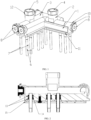
FIG. 1 is a structural diagram of a multi-manifold connector according to the present disclosure; and -
FIG. 2 is a section view of the multi-manifold connector according to the present disclosure. - As shown in
FIGS. 1 and 2 , an embodiment of the present disclosure provides a multi-manifold connector. The multi-manifold connector includes base 1, hot water connector 2, and cold water connector 3. The hot water connector 2 and the cold water connector 3 are arranged on the base 1. The hot water connector 2 is provided withwater inlet 4. The cold water connector 3 is provided with water outlet 5. A bottom of the base 1 is provided with multiplefirst water pipes 6 and multiple second water pipes 7. The multiplefirst water pipes 6 run through the base 1 and are communicated with the hot water connector 2. The multiple second water pipes 7 run through the base 1 and are communicated with the cold water connector 3.
In the above solution, hot water flows in from thewater inlet 4 of the hot water connector 2 and flows out from the multiplefirst water pipes 6 to various areas that require heat dissipation. Cold water generated by heat dissipation flows into the cold water connector 3 from the multiple
second water pipes 7, and finally flows back to a water storage area from the water outlet 5 of the cold water connector 3. In this way, the water is circulated. - In a preferred solution, as shown in
FIG. 1 , each of the hot water connector 2 and the cold water connector 3 is provided with plug 8. The plug 8 is matched with circlip 9. The circlip 9 is matched withstopper 10. The hot water connector 2 and the cold water connector 3 are L-shaped. A periphery of the base 1 extends outward to formsupport plate 11. Each of thewater inlet 4 and the water outlet 5 is provided withwater pipe joint 11. - In the above solution, the plug 8, the circlip 9, and the
stopper 10 have the following effects. The circlip 9 ensures the seal of the plug 8. Thestopper 10 is configured to limit the position of the circlip 9 and prevent the circlip 9 from being misaligned, thereby ultimately forming a sealed space inside the hot water connector 2 and the cold water connector 3. Thesupport plate 11 is configured to support the hot water connector 2 and the cold water connector 3. - In the above solution, as shown in
FIGS. 1 and 2 , the base 1, the hot water connector 2, and the cold water connector 3 are integrally formed. A sealing structure is provided between thefirst water pipes 6 and the hot water connector 2, and a sealing structure is provided between the second water pipes 7 and the cold water connector 3. The sealing structure includes twosealing rings 13 and aspacer 14 provided between the twosealing rings 13. The bottom of the base 1 is further provided withcover plate 15. Thefirst water pipes 6 and the second water pipes 7 are arranged on the base 1 through thecover plate 15 and matched bolts. - The implementations of the present disclosure are described in detail above in combination with the drawings, but the present disclosure is not limited to the described implementations. For those skilled in the art, various changes, modifications, replacements, and variations made to the implementations without departing from the principle and spirit of the present disclosure still fall within the protection scope of the present disclosure.
Claims (8)
- A multi-manifold connector, comprising a base (1), a hot water connector (2), and a cold water connector (3), wherein the hot water connector (2) and the cold water connector (3) are arranged on the base (1); the hot water connector (2) is provided with a water inlet (4); the cold water connector (3) is provided with a water outlet (5); a bottom of the base (1) is provided with multiple first water pipes (6) and multiple second water pipes (7); the multiple first water pipes (6) run through the base (1) and are communicated with the hot water connector (2); and the multiple second water pipes (7) run through the base (1) and are communicated with the cold water connector (3).
- The multi-manifold connector according to claim 1, wherein each of the hot water connector (2) and the cold water connector (3) is provided with a plug (8); the plug (8) is matched with a circlip (9); and the circlip (9) is matched with a stopper (10).
- The multi-manifold connector according to claim 1, wherein the hot water connector (2) and the cold water connector (3) are L-shaped.
- The multi-manifold connector according to claim 1, wherein a periphery of the base (1) extends outward to form a support plate (11).
- The multi-manifold connector according to claim 1, wherein each of the water inlet (4) and the water outlet (5) is provided with a water pipe joint (12).
- The multi-manifold connector according to claim 1, wherein the base (1), the hot water connector (2), and the cold water connector (3) are integrally formed.
- The multi-manifold connector according to claim 1, wherein a sealing structure is provided between the first water pipes (6) and the hot water connector (2), and a sealing structure is provided between the second water pipes (7) and the cold water connector (3); and the sealing structure comprises two sealing rings (13) and a spacer (14) provided between the two sealing rings (13).
- The multi-manifold connector according to claim 1, wherein the bottom of the base (1) is further provided with a cover plate (15); and the first water pipes (6) and the second water pipes (7) are arranged on the base (1) through the cover plate (15) and matched bolts.
Applications Claiming Priority (2)
| Application Number | Priority Date | Filing Date | Title |
|---|---|---|---|
| CN202120745449.6U CN215410752U (en) | 2021-04-13 | 2021-04-13 | Multi-manifold connector |
| PCT/CN2022/086831 WO2022218378A1 (en) | 2021-04-13 | 2022-04-14 | Multi-manifold connector |
Publications (4)
| Publication Number | Publication Date |
|---|---|
| EP4325108A1 true EP4325108A1 (en) | 2024-02-21 |
| EP4325108A4 EP4325108A4 (en) | 2025-06-04 |
| EP4325108C0 EP4325108C0 (en) | 2026-01-14 |
| EP4325108B1 EP4325108B1 (en) | 2026-01-14 |
Family
ID=79671182
Family Applications (1)
| Application Number | Title | Priority Date | Filing Date |
|---|---|---|---|
| EP22787600.0A Active EP4325108B1 (en) | 2021-04-13 | 2022-04-14 | Multi-manifold connector |
Country Status (4)
| Country | Link |
|---|---|
| US (1) | US12228232B2 (en) |
| EP (1) | EP4325108B1 (en) |
| CN (1) | CN215410752U (en) |
| WO (1) | WO2022218378A1 (en) |
Families Citing this family (2)
| Publication number | Priority date | Publication date | Assignee | Title |
|---|---|---|---|---|
| CN215410752U (en) | 2021-04-13 | 2022-01-04 | 珠海吉泰克燃气设备技术有限公司 | Multi-manifold connector |
| CN115493012B (en) * | 2022-09-29 | 2026-03-03 | 浙江吉利控股集团有限公司 | Vehicle pipeline installation head, pipeline structure and vehicle |
Family Cites Families (19)
| Publication number | Priority date | Publication date | Assignee | Title |
|---|---|---|---|---|
| US4498693A (en) * | 1983-02-22 | 1985-02-12 | Schindele Ernst F | Rail system with passageways for the conduction of fluid flow |
| US5050631A (en) * | 1989-08-23 | 1991-09-24 | Honda Giken Kogyo Kabushiki Kaisha | Fluid diverging system |
| GB2239068B (en) * | 1989-12-06 | 1993-10-13 | Powered Showers Plc | Pipe connector device |
| CN2627420Y (en) * | 2003-07-07 | 2004-07-21 | 赵微微 | Split solar water heater |
| KR200360433Y1 (en) * | 2004-06-16 | 2004-08-30 | 이준식 | Case for distributor of hot water/cool water |
| SE532136C2 (en) * | 2006-10-04 | 2009-10-27 | Tour & Andersson Ab | Device for an energy distribution system |
| KR100757492B1 (en) * | 2006-11-29 | 2007-09-13 | 이용춘 | Combined structure of wall-embedded cold and hot water distributor for easy fitting of cold and hot water soft pipes |
| CN101957051A (en) * | 2010-05-18 | 2011-01-26 | 周剑冰 | Electric water heater |
| US10457540B2 (en) * | 2010-07-09 | 2019-10-29 | Wayne Fueling Systems Sweden Ab | Kit of parts for assembling a hose connection, a fuel dispensing unit having such a hose connection, and a method for assembling such a hose connection |
| CN203477724U (en) * | 2013-08-21 | 2014-03-12 | 宁波名德建材有限公司 | Multi-way ball valve water segregator |
| NO341490B1 (en) * | 2015-06-18 | 2017-11-27 | Braathen Thor F | A cabinet and method for making a cabinet |
| US20180030697A1 (en) * | 2016-07-29 | 2018-02-01 | Eg Products Corp. | Water Tap Assembly |
| US11226642B2 (en) * | 2017-04-03 | 2022-01-18 | Fmc Technologies, Inc. | Zipper manifold arrangement for trailer deployment |
| US10160149B2 (en) * | 2017-04-05 | 2018-12-25 | Plastixs, LLC | Access to cooling manifold valve controls in injection molding operations |
| CN109268606A (en) * | 2018-11-11 | 2019-01-25 | 荣树成 | A kind of interior water supply pipline system |
| NO346855B1 (en) * | 2019-05-28 | 2023-01-30 | Braathen Thor F | A distribution pipe for a distribution pipe line for the distribution of water to various locations in a building body |
| CN215410752U (en) * | 2021-04-13 | 2022-01-04 | 珠海吉泰克燃气设备技术有限公司 | Multi-manifold connector |
| US11359474B1 (en) * | 2021-07-16 | 2022-06-14 | Profrac Services, Llc | Systems and methods for distributing fluids at a wellsite |
| CA3178881A1 (en) * | 2021-10-14 | 2023-04-14 | Scout Surface Solutions, Llc | Fluid conduit assembly for a fluid supply system |
-
2021
- 2021-04-13 CN CN202120745449.6U patent/CN215410752U/en active Active
-
2022
- 2022-04-14 EP EP22787600.0A patent/EP4325108B1/en active Active
- 2022-04-14 US US18/286,769 patent/US12228232B2/en active Active
- 2022-04-14 WO PCT/CN2022/086831 patent/WO2022218378A1/en not_active Ceased
Also Published As
| Publication number | Publication date |
|---|---|
| EP4325108C0 (en) | 2026-01-14 |
| EP4325108A4 (en) | 2025-06-04 |
| US20240191821A1 (en) | 2024-06-13 |
| US12228232B2 (en) | 2025-02-18 |
| WO2022218378A1 (en) | 2022-10-20 |
| EP4325108B1 (en) | 2026-01-14 |
| CN215410752U (en) | 2022-01-04 |
Similar Documents
| Publication | Publication Date | Title |
|---|---|---|
| US20240191821A1 (en) | Multi-manifold connector | |
| CN206770160U (en) | Compressor packing seals cooling structure | |
| CN210570121U (en) | Water-cooling pipe | |
| CN218998680U (en) | Water cooling plate heat radiation structure welded through sealing ring | |
| CN209045303U (en) | A kind of antiseep gilled radiator | |
| CN102331199A (en) | Combined oil radiator | |
| CN214172198U (en) | Energy-saving improved pipeline structure of boiler | |
| CN211009145U (en) | Heat conduction oil pump that leakproofness is good | |
| CN210179118U (en) | High-temperature fluid pipeline connecting device | |
| CN214371979U (en) | Flange connecting pipe for heat exchanger | |
| CN220062700U (en) | Four-channel radiator | |
| CN221223447U (en) | Double-sealing aluminum radiator | |
| CN211926582U (en) | Disc type heat exchanger | |
| CN203081911U (en) | Cooler used on hydraulic system | |
| CN207407707U (en) | A kind of pasteurizing device heat exchanger | |
| CN213629306U (en) | Pipeline connecting structure of heating stove | |
| CN224051105U (en) | Heating installation pipe connecting device with strong sealing structure | |
| CN214043347U (en) | Split type fin of large-scale transformer | |
| CN218884729U (en) | Heat exchange unit with heat supply energy-saving structure | |
| CN205279799U (en) | Cylindrical heat exchanger | |
| CN218565794U (en) | Grid structure of flat plate type heat collector and water heater | |
| CN218033723U (en) | Hot water heating device of ultralow-temperature air source heat pump | |
| CN217483305U (en) | Wave node heat exchange tube heat exchanger | |
| CN219798032U (en) | Pipeline type heat exchanger | |
| CN112628713B (en) | An improved pipeline structure for boiler energy saving |
Legal Events
| Date | Code | Title | Description |
|---|---|---|---|
| STAA | Information on the status of an ep patent application or granted ep patent |
Free format text: STATUS: THE INTERNATIONAL PUBLICATION HAS BEEN MADE |
|
| PUAI | Public reference made under article 153(3) epc to a published international application that has entered the european phase |
Free format text: ORIGINAL CODE: 0009012 |
|
| STAA | Information on the status of an ep patent application or granted ep patent |
Free format text: STATUS: REQUEST FOR EXAMINATION WAS MADE |
|
| 17P | Request for examination filed |
Effective date: 20231110 |
|
| AK | Designated contracting states |
Kind code of ref document: A1 Designated state(s): AL AT BE BG CH CY CZ DE DK EE ES FI FR GB GR HR HU IE IS IT LI LT LU LV MC MK MT NL NO PL PT RO RS SE SI SK SM TR |
|
| XX | Miscellaneous (additional remarks) |
Free format text: THE FILING DATE OF THE INTERNATIONAL APPLICATION IS WITHIN TWO MONTHS FROM THE DATE OF EXPIRATION OF THE PRIORITY PERIOD (R. 26BIS.3 PCT). |
|
| DAV | Request for validation of the european patent (deleted) | ||
| DAX | Request for extension of the european patent (deleted) | ||
| RIC1 | Information provided on ipc code assigned before grant |
Ipc: F16L 41/03 20060101AFI20250210BHEP |
|
| A4 | Supplementary search report drawn up and despatched |
Effective date: 20250508 |
|
| RIC1 | Information provided on ipc code assigned before grant |
Ipc: F16L 41/03 20060101AFI20250430BHEP |
|
| REG | Reference to a national code |
Ref country code: DE Ref legal event code: R079 Free format text: PREVIOUS MAIN CLASS: F16L0041030000 Ipc: F16L0037040000 Ref document number: 602022028513 Country of ref document: DE |
|
| GRAP | Despatch of communication of intention to grant a patent |
Free format text: ORIGINAL CODE: EPIDOSNIGR1 |
|
| STAA | Information on the status of an ep patent application or granted ep patent |
Free format text: STATUS: GRANT OF PATENT IS INTENDED |
|
| RIC1 | Information provided on ipc code assigned before grant |
Ipc: F16L 37/04 20060101AFI20251014BHEP Ipc: F28F 9/06 20060101ALI20251014BHEP Ipc: F28F 9/26 20060101ALI20251014BHEP Ipc: F16L 41/03 20060101ALI20251014BHEP |
|
| GRAS | Grant fee paid |
Free format text: ORIGINAL CODE: EPIDOSNIGR3 |
|
| INTG | Intention to grant announced |
Effective date: 20251103 |
|
| GRAA | (expected) grant |
Free format text: ORIGINAL CODE: 0009210 |
|
| STAA | Information on the status of an ep patent application or granted ep patent |
Free format text: STATUS: THE PATENT HAS BEEN GRANTED |
|
| AK | Designated contracting states |
Kind code of ref document: B1 Designated state(s): AL AT BE BG CH CY CZ DE DK EE ES FI FR GB GR HR HU IE IS IT LI LT LU LV MC MK MT NL NO PL PT RO RS SE SI SK SM TR |
|
| REG | Reference to a national code |
Ref country code: CH Ref legal event code: F10 Free format text: ST27 STATUS EVENT CODE: U-0-0-F10-F00 (AS PROVIDED BY THE NATIONAL OFFICE) Effective date: 20260114 Ref country code: GB Ref legal event code: FG4D |
|
| XX | Miscellaneous (additional remarks) |
Free format text: THE FILING DATE OF THE INTERNATIONAL APPLICATION IS WITHIN TWO MONTHS FROM THE DATE OF EXPIRATION OF THE PRIORITY PERIOD (R. 26BIS.3 PCT) |
|
| REG | Reference to a national code |
Ref country code: DE Ref legal event code: R096 Ref document number: 602022028513 Country of ref document: DE |
|
| REG | Reference to a national code |
Ref country code: IE Ref legal event code: FG4D |
|
| U01 | Request for unitary effect filed |
Effective date: 20260115 |
|
| U07 | Unitary effect registered |
Designated state(s): AT BE BG DE DK EE FI FR IT LT LU LV MT NL PT RO SE SI Effective date: 20260121 |
|
| U20 | Renewal fee for the european patent with unitary effect paid |
Year of fee payment: 5 Effective date: 20260212 |
|
| PGFP | Annual fee paid to national office [announced via postgrant information from national office to epo] |
Ref country code: GB Payment date: 20260223 Year of fee payment: 5 |