EP4325016A1 - Window assembly, vehicle door and vehicle - Google Patents
Window assembly, vehicle door and vehicle Download PDFInfo
- Publication number
- EP4325016A1 EP4325016A1 EP22191036.7A EP22191036A EP4325016A1 EP 4325016 A1 EP4325016 A1 EP 4325016A1 EP 22191036 A EP22191036 A EP 22191036A EP 4325016 A1 EP4325016 A1 EP 4325016A1
- Authority
- EP
- European Patent Office
- Prior art keywords
- window
- drive
- stator
- rotor
- mobile
- Prior art date
- Legal status (The legal status is an assumption and is not a legal conclusion. Google has not performed a legal analysis and makes no representation as to the accuracy of the status listed.)
- Granted
Links
Images


Classifications
-
- E—FIXED CONSTRUCTIONS
- E05—LOCKS; KEYS; WINDOW OR DOOR FITTINGS; SAFES
- E05F—DEVICES FOR MOVING WINGS INTO OPEN OR CLOSED POSITION; CHECKS FOR WINGS; WING FITTINGS NOT OTHERWISE PROVIDED FOR, CONCERNED WITH THE FUNCTIONING OF THE WING
- E05F15/00—Power-operated mechanisms for wings
- E05F15/60—Power-operated mechanisms for wings using electrical actuators
- E05F15/603—Power-operated mechanisms for wings using electrical actuators using rotary electromotors
- E05F15/665—Power-operated mechanisms for wings using electrical actuators using rotary electromotors for vertically-sliding wings
- E05F15/689—Power-operated mechanisms for wings using electrical actuators using rotary electromotors for vertically-sliding wings specially adapted for vehicle windows
-
- B—PERFORMING OPERATIONS; TRANSPORTING
- B60—VEHICLES IN GENERAL
- B60J—WINDOWS, WINDSCREENS, NON-FIXED ROOFS, DOORS, OR SIMILAR DEVICES FOR VEHICLES; REMOVABLE EXTERNAL PROTECTIVE COVERINGS SPECIALLY ADAPTED FOR VEHICLES
- B60J5/00—Doors
- B60J5/04—Doors arranged at the vehicle sides
- B60J5/0401—Upper door structure
- B60J5/0402—Upper door structure window frame details, including sash guides and glass runs
-
- E—FIXED CONSTRUCTIONS
- E05—LOCKS; KEYS; WINDOW OR DOOR FITTINGS; SAFES
- E05F—DEVICES FOR MOVING WINGS INTO OPEN OR CLOSED POSITION; CHECKS FOR WINGS; WING FITTINGS NOT OTHERWISE PROVIDED FOR, CONCERNED WITH THE FUNCTIONING OF THE WING
- E05F15/00—Power-operated mechanisms for wings
- E05F15/60—Power-operated mechanisms for wings using electrical actuators
- E05F15/603—Power-operated mechanisms for wings using electrical actuators using rotary electromotors
- E05F15/665—Power-operated mechanisms for wings using electrical actuators using rotary electromotors for vertically-sliding wings
- E05F15/689—Power-operated mechanisms for wings using electrical actuators using rotary electromotors for vertically-sliding wings specially adapted for vehicle windows
- E05F15/6896—Power-operated mechanisms for wings using electrical actuators using rotary electromotors for vertically-sliding wings specially adapted for vehicle windows operated by screw mechanism
-
- E—FIXED CONSTRUCTIONS
- E05—LOCKS; KEYS; WINDOW OR DOOR FITTINGS; SAFES
- E05F—DEVICES FOR MOVING WINGS INTO OPEN OR CLOSED POSITION; CHECKS FOR WINGS; WING FITTINGS NOT OTHERWISE PROVIDED FOR, CONCERNED WITH THE FUNCTIONING OF THE WING
- E05F15/00—Power-operated mechanisms for wings
- E05F15/60—Power-operated mechanisms for wings using electrical actuators
- E05F15/603—Power-operated mechanisms for wings using electrical actuators using rotary electromotors
- E05F15/665—Power-operated mechanisms for wings using electrical actuators using rotary electromotors for vertically-sliding wings
- E05F15/689—Power-operated mechanisms for wings using electrical actuators using rotary electromotors for vertically-sliding wings specially adapted for vehicle windows
- E05F15/697—Motor units therefor, e.g. geared motors
-
- E—FIXED CONSTRUCTIONS
- E05—LOCKS; KEYS; WINDOW OR DOOR FITTINGS; SAFES
- E05Y—INDEXING SCHEME ASSOCIATED WITH SUBCLASSES E05D AND E05F, RELATING TO CONSTRUCTION ELEMENTS, ELECTRIC CONTROL, POWER SUPPLY, POWER SIGNAL OR TRANSMISSION, USER INTERFACES, MOUNTING OR COUPLING, DETAILS, ACCESSORIES, AUXILIARY OPERATIONS NOT OTHERWISE PROVIDED FOR, APPLICATION THEREOF
- E05Y2201/00—Constructional elements; Accessories therefor
- E05Y2201/40—Motors; Magnets; Springs; Weights; Accessories therefor
- E05Y2201/43—Motors
- E05Y2201/434—Electromotors; Details thereof
-
- E—FIXED CONSTRUCTIONS
- E05—LOCKS; KEYS; WINDOW OR DOOR FITTINGS; SAFES
- E05Y—INDEXING SCHEME ASSOCIATED WITH SUBCLASSES E05D AND E05F, RELATING TO CONSTRUCTION ELEMENTS, ELECTRIC CONTROL, POWER SUPPLY, POWER SIGNAL OR TRANSMISSION, USER INTERFACES, MOUNTING OR COUPLING, DETAILS, ACCESSORIES, AUXILIARY OPERATIONS NOT OTHERWISE PROVIDED FOR, APPLICATION THEREOF
- E05Y2201/00—Constructional elements; Accessories therefor
- E05Y2201/40—Motors; Magnets; Springs; Weights; Accessories therefor
- E05Y2201/43—Motors
- E05Y2201/434—Electromotors; Details thereof
- E05Y2201/438—Rotors
-
- E—FIXED CONSTRUCTIONS
- E05—LOCKS; KEYS; WINDOW OR DOOR FITTINGS; SAFES
- E05Y—INDEXING SCHEME ASSOCIATED WITH SUBCLASSES E05D AND E05F, RELATING TO CONSTRUCTION ELEMENTS, ELECTRIC CONTROL, POWER SUPPLY, POWER SIGNAL OR TRANSMISSION, USER INTERFACES, MOUNTING OR COUPLING, DETAILS, ACCESSORIES, AUXILIARY OPERATIONS NOT OTHERWISE PROVIDED FOR, APPLICATION THEREOF
- E05Y2201/00—Constructional elements; Accessories therefor
- E05Y2201/40—Motors; Magnets; Springs; Weights; Accessories therefor
- E05Y2201/43—Motors
- E05Y2201/434—Electromotors; Details thereof
- E05Y2201/442—Stators
-
- E—FIXED CONSTRUCTIONS
- E05—LOCKS; KEYS; WINDOW OR DOOR FITTINGS; SAFES
- E05Y—INDEXING SCHEME ASSOCIATED WITH SUBCLASSES E05D AND E05F, RELATING TO CONSTRUCTION ELEMENTS, ELECTRIC CONTROL, POWER SUPPLY, POWER SIGNAL OR TRANSMISSION, USER INTERFACES, MOUNTING OR COUPLING, DETAILS, ACCESSORIES, AUXILIARY OPERATIONS NOT OTHERWISE PROVIDED FOR, APPLICATION THEREOF
- E05Y2201/00—Constructional elements; Accessories therefor
- E05Y2201/60—Suspension or transmission members; Accessories therefor
- E05Y2201/622—Suspension or transmission members elements
- E05Y2201/684—Rails; Tracks
-
- E—FIXED CONSTRUCTIONS
- E05—LOCKS; KEYS; WINDOW OR DOOR FITTINGS; SAFES
- E05Y—INDEXING SCHEME ASSOCIATED WITH SUBCLASSES E05D AND E05F, RELATING TO CONSTRUCTION ELEMENTS, ELECTRIC CONTROL, POWER SUPPLY, POWER SIGNAL OR TRANSMISSION, USER INTERFACES, MOUNTING OR COUPLING, DETAILS, ACCESSORIES, AUXILIARY OPERATIONS NOT OTHERWISE PROVIDED FOR, APPLICATION THEREOF
- E05Y2201/00—Constructional elements; Accessories therefor
- E05Y2201/60—Suspension or transmission members; Accessories therefor
- E05Y2201/622—Suspension or transmission members elements
- E05Y2201/696—Screw mechanisms
-
- E—FIXED CONSTRUCTIONS
- E05—LOCKS; KEYS; WINDOW OR DOOR FITTINGS; SAFES
- E05Y—INDEXING SCHEME ASSOCIATED WITH SUBCLASSES E05D AND E05F, RELATING TO CONSTRUCTION ELEMENTS, ELECTRIC CONTROL, POWER SUPPLY, POWER SIGNAL OR TRANSMISSION, USER INTERFACES, MOUNTING OR COUPLING, DETAILS, ACCESSORIES, AUXILIARY OPERATIONS NOT OTHERWISE PROVIDED FOR, APPLICATION THEREOF
- E05Y2201/00—Constructional elements; Accessories therefor
- E05Y2201/60—Suspension or transmission members; Accessories therefor
- E05Y2201/622—Suspension or transmission members elements
- E05Y2201/696—Screw mechanisms
- E05Y2201/70—Nuts
-
- E—FIXED CONSTRUCTIONS
- E05—LOCKS; KEYS; WINDOW OR DOOR FITTINGS; SAFES
- E05Y—INDEXING SCHEME ASSOCIATED WITH SUBCLASSES E05D AND E05F, RELATING TO CONSTRUCTION ELEMENTS, ELECTRIC CONTROL, POWER SUPPLY, POWER SIGNAL OR TRANSMISSION, USER INTERFACES, MOUNTING OR COUPLING, DETAILS, ACCESSORIES, AUXILIARY OPERATIONS NOT OTHERWISE PROVIDED FOR, APPLICATION THEREOF
- E05Y2201/00—Constructional elements; Accessories therefor
- E05Y2201/60—Suspension or transmission members; Accessories therefor
- E05Y2201/622—Suspension or transmission members elements
- E05Y2201/696—Screw mechanisms
- E05Y2201/702—Spindles; Worms
-
- E—FIXED CONSTRUCTIONS
- E05—LOCKS; KEYS; WINDOW OR DOOR FITTINGS; SAFES
- E05Y—INDEXING SCHEME ASSOCIATED WITH SUBCLASSES E05D AND E05F, RELATING TO CONSTRUCTION ELEMENTS, ELECTRIC CONTROL, POWER SUPPLY, POWER SIGNAL OR TRANSMISSION, USER INTERFACES, MOUNTING OR COUPLING, DETAILS, ACCESSORIES, AUXILIARY OPERATIONS NOT OTHERWISE PROVIDED FOR, APPLICATION THEREOF
- E05Y2600/00—Mounting or coupling arrangements for elements provided for in this subclass
- E05Y2600/40—Mounting location; Visibility of the elements
- E05Y2600/41—Concealed
-
- E—FIXED CONSTRUCTIONS
- E05—LOCKS; KEYS; WINDOW OR DOOR FITTINGS; SAFES
- E05Y—INDEXING SCHEME ASSOCIATED WITH SUBCLASSES E05D AND E05F, RELATING TO CONSTRUCTION ELEMENTS, ELECTRIC CONTROL, POWER SUPPLY, POWER SIGNAL OR TRANSMISSION, USER INTERFACES, MOUNTING OR COUPLING, DETAILS, ACCESSORIES, AUXILIARY OPERATIONS NOT OTHERWISE PROVIDED FOR, APPLICATION THEREOF
- E05Y2800/00—Details, accessories and auxiliary operations not otherwise provided for
- E05Y2800/20—Combinations of elements
- E05Y2800/23—Combinations of elements of elements of different categories
- E05Y2800/232—Combinations of elements of elements of different categories of motors and transmissions
-
- E—FIXED CONSTRUCTIONS
- E05—LOCKS; KEYS; WINDOW OR DOOR FITTINGS; SAFES
- E05Y—INDEXING SCHEME ASSOCIATED WITH SUBCLASSES E05D AND E05F, RELATING TO CONSTRUCTION ELEMENTS, ELECTRIC CONTROL, POWER SUPPLY, POWER SIGNAL OR TRANSMISSION, USER INTERFACES, MOUNTING OR COUPLING, DETAILS, ACCESSORIES, AUXILIARY OPERATIONS NOT OTHERWISE PROVIDED FOR, APPLICATION THEREOF
- E05Y2800/00—Details, accessories and auxiliary operations not otherwise provided for
- E05Y2800/26—Form or shape
- E05Y2800/262—Form or shape column shaped
-
- E—FIXED CONSTRUCTIONS
- E05—LOCKS; KEYS; WINDOW OR DOOR FITTINGS; SAFES
- E05Y—INDEXING SCHEME ASSOCIATED WITH SUBCLASSES E05D AND E05F, RELATING TO CONSTRUCTION ELEMENTS, ELECTRIC CONTROL, POWER SUPPLY, POWER SIGNAL OR TRANSMISSION, USER INTERFACES, MOUNTING OR COUPLING, DETAILS, ACCESSORIES, AUXILIARY OPERATIONS NOT OTHERWISE PROVIDED FOR, APPLICATION THEREOF
- E05Y2800/00—Details, accessories and auxiliary operations not otherwise provided for
- E05Y2800/26—Form or shape
- E05Y2800/28—Form or shape tubular, annular
-
- E—FIXED CONSTRUCTIONS
- E05—LOCKS; KEYS; WINDOW OR DOOR FITTINGS; SAFES
- E05Y—INDEXING SCHEME ASSOCIATED WITH SUBCLASSES E05D AND E05F, RELATING TO CONSTRUCTION ELEMENTS, ELECTRIC CONTROL, POWER SUPPLY, POWER SIGNAL OR TRANSMISSION, USER INTERFACES, MOUNTING OR COUPLING, DETAILS, ACCESSORIES, AUXILIARY OPERATIONS NOT OTHERWISE PROVIDED FOR, APPLICATION THEREOF
- E05Y2800/00—Details, accessories and auxiliary operations not otherwise provided for
- E05Y2800/26—Form or shape
- E05Y2800/292—Form or shape having apertures
- E05Y2800/296—Slots
-
- E—FIXED CONSTRUCTIONS
- E05—LOCKS; KEYS; WINDOW OR DOOR FITTINGS; SAFES
- E05Y—INDEXING SCHEME ASSOCIATED WITH SUBCLASSES E05D AND E05F, RELATING TO CONSTRUCTION ELEMENTS, ELECTRIC CONTROL, POWER SUPPLY, POWER SIGNAL OR TRANSMISSION, USER INTERFACES, MOUNTING OR COUPLING, DETAILS, ACCESSORIES, AUXILIARY OPERATIONS NOT OTHERWISE PROVIDED FOR, APPLICATION THEREOF
- E05Y2800/00—Details, accessories and auxiliary operations not otherwise provided for
- E05Y2800/67—Materials; Strength alteration thereof
- E05Y2800/672—Glass
-
- E—FIXED CONSTRUCTIONS
- E05—LOCKS; KEYS; WINDOW OR DOOR FITTINGS; SAFES
- E05Y—INDEXING SCHEME ASSOCIATED WITH SUBCLASSES E05D AND E05F, RELATING TO CONSTRUCTION ELEMENTS, ELECTRIC CONTROL, POWER SUPPLY, POWER SIGNAL OR TRANSMISSION, USER INTERFACES, MOUNTING OR COUPLING, DETAILS, ACCESSORIES, AUXILIARY OPERATIONS NOT OTHERWISE PROVIDED FOR, APPLICATION THEREOF
- E05Y2900/00—Application of doors, windows, wings or fittings thereof
- E05Y2900/50—Application of doors, windows, wings or fittings thereof for vehicles
- E05Y2900/516—Application of doors, windows, wings or fittings thereof for vehicles for trucks or trailers
-
- E—FIXED CONSTRUCTIONS
- E05—LOCKS; KEYS; WINDOW OR DOOR FITTINGS; SAFES
- E05Y—INDEXING SCHEME ASSOCIATED WITH SUBCLASSES E05D AND E05F, RELATING TO CONSTRUCTION ELEMENTS, ELECTRIC CONTROL, POWER SUPPLY, POWER SIGNAL OR TRANSMISSION, USER INTERFACES, MOUNTING OR COUPLING, DETAILS, ACCESSORIES, AUXILIARY OPERATIONS NOT OTHERWISE PROVIDED FOR, APPLICATION THEREOF
- E05Y2900/00—Application of doors, windows, wings or fittings thereof
- E05Y2900/50—Application of doors, windows, wings or fittings thereof for vehicles
- E05Y2900/53—Type of wing
- E05Y2900/55—Windows
Definitions
- the disclosure relates generally to the technical field of vehicle windows.
- the disclosure relates to a window assembly for a vehicle, to a vehicle door and to a vehicle.
- the disclosure can be applied in heavy-duty vehicles, such as trucks, buses, and construction equipment. Although the disclosure will be described with respect to a particular vehicle, the disclosure is not restricted to any particular vehicle.
- the cab of known vehicles such as trucks and cars usually includes lateral doors with windows, so that the driver and passengers may see the area outside from the vehicle through the window when sitting inside the vehicle.
- the window of each door is usually mobile between a closed position and an open position, e.g. for venting the interior of the vehicle.
- Some vehicles also have fixed windows, for improving the driver and passenger's visibility.
- the surface area of the windows is often limited by the mechanism that drives the mobile window between the open and closed positions.
- available space for arranging windows is limited by the frame structure of the door itself but also by said mechanism, which is usually arranged inside the doord, at a bottom part of the door under the mobile window.
- the disclosure proposes to improve a driver's and/or passengers visibility, while still enabling mobility of the window of a vehicle.
- An aspect of the disclosure concerns a window assembly for a vehicle, the window assembly comprising a first drive, comprising a first stator and a first rotor, the first rotor being arranged around the first stator for rotating relative to the first stator, about a first longitudinal axis fixed relative to the first stator, when the first drive is electrically powered.
- the window assembly futher comprises a mobile window, having a transversal edge and a first longitudinal edge, the mobile window being configured for sliding relative to the first stator substantially parallel to the first longitudinal axis, between an open position where the transversal edge is positioned at a first longitudinal end of the first drive and the first longitudinal edge is positioned along the first drive, and a closed position where the transversal edge is positioned at a second longitudinal end of the first drive and where the first longitudinal edge is positioned passed the first drive along the first longitudinal axis.
- the window assembly further comprises a first transmission mechanism, the mobile window being driven between the open position and the closed position by the rotation of the first rotor, via the first transmission mechanism.
- the first longitudinal axis When in use, the first longitudinal axis may substantially be vertical or vertical and the mobile window, when in the closed position, positioned passed the first drive in an upward direction parallel to the first longitudinal axis.
- a technical effect is that space is available for placing another window, such as a fixed window, beside the first drive, without any element blocking see-through said other window in this area.
- the first drive and the first transmission mechanism may easily be arranged along a frame of the window assembly, such as a door frame, considering that the first drive and first transmission mechanism may easily have, overall, an elongated shape along the first longitudinal axis.
- the first drive may advantageously be arranged along an edge of the door, parallel to the first longitudinal axis, leaving most of the door available for placing the windows.
- the mobile window may be superposed with said other window when in the open position, still enabling see-through the superposed windows.
- the mobile window may be positioned passed said other window when the mobile window is in the closed position, enabling see through the two windows at their respective locations.
- the window assembly leaves more available space for more window surface, thereby improving the driver's and/or passenger's visibility.
- the better visibility may improve safety in maneuvering of the vehicle, in particular if the vehicle is a large ground vehicle such as a truck, a construction vehicle, a mining vehicle, a van, a coach or the like.
- the window assembly further comprises a fixed window, fixed relative to the first stator and positioned along the first drive, wherein the mobile window is superposed with the fixed window when the mobile window is in the open position and wherein the mobile window is positioned passed the fixed window when the mobile window is in the closed position.
- a technical effect is that the fixed window provides more visibility while not being obstructed by any part required for sliding the mobile window.
- the window assembly can especially be used for equipping a vehicle door, with the fixed window at the bottom and the mobile window at the top when in the closed position.
- the first drive comprises: a first attachment, for attaching the first stator to a frame of the window assembly, the mobile window being mobile relative to the frame between the closed and the open position, the first attachment being positioned at the first longitudinal end of the first drive, and a second attachment, for attaching the first stator to the frame, the second attachment being positioned at a second longitudinal end of the first drive, opposite to the first longitudinal end of the first drive, the first rotor being arranged between the first attachment and the second attachment.
- a technical effect is that the first drive may be reliably attached to the frame of the vehicle by both longitudinal ends, while being compact for leaving available space for said other window, in particular fixed window. This arrangement is especially useful if the window assembly is installed in the vehicle door.
- the first transmission mechanism comprises a lead screw, arranged around the first rotor and secured to the first rotor, and a nut, secured to the mobile window and geared with the lead screw.
- a technical effect is that the transmission mechanism may be packed with the first drive in a compact manner, while being mechanically efficient and easy maintenance.
- the first transmission mechanism comprises a slider, attached to the mobile window, and a sliding guide, fixed relative to the first stator, the slider being guided by the sliding guide for guiding the sliding of the mobile window between the open position and the closed position.
- the window assembly further comprises a second drive, comprising a second stator and a second rotor, the second rotor being arranged around the second rotor for rotating relative to the second stator, about a second longitudinal axis fixed relative to the second stator and parallel to the first longitudinal axis, when the second drive is electrically powered, the mobile window having a second longitudinal edge opposite to the first longitudinal edge, the transversal edge connecting the first longitudinal edge to the second longitudinal edge, the transversal edge being positioned at a first longitudinal end of the second drive when the mobile window is in the open position, the second longitudinal edge being positioned along the second drive when the mobile window is in the open position, the second longitudinal edge being positioned passed the second drive along the second longitudinal axis when the mobile window is in the closed position.
- a second drive comprising a second stator and a second rotor, the second rotor being arranged around the second rotor for rotating relative to the second stator, about a second longitudinal axis fixed relative to the second stator and parallel to the
- the window assembly may further comprise a second transmission mechanism, the mobile window being driven between the open position and the closed position by rotation of the second rotor, via the second transmission mechanism, in addition to being driven by rotation of the first rotor.
- a technical effect is that the first drive and the second drive may be smaller, as their power for moving the mobile window is combined.
- said other window e.g. fixed window
- said other window may be placed between the first drive and the second drive.
- only one drive is provided, e.g. only the first drive and the first transmission mechanism but not the second drive nor the second transmission mechanism.
- a slider and sliding guide may be provided at the second longitudinal edge of the mobile window for guiding the sliding of the mobile window between the open and the closed positions.
- Another aspect of the disclosure concerns a vehicle door, comprising the window assembly as defined above.
- Another aspect of the disclosure concerns a vehicle, comprising a cab, wherein the cab comprises the window assembly as defined above.
- the vehicle is a heavy-duty ground vehicle, such as a truck, a coach, a bus or a van.
- the disclosure proposes to improve a driver's visibility and/or to reduce the flowing of water along an area of a ground vehicle to be avoided, such as a side window of the ground vehicle.
- FIG. 1 shows a ground vehicle 1 in box 1A.
- the vehicle 1 includes a cab 2 with a window assembly 3, here belonging to a lateral door 4.
- the window assembly 3 comprises a frame 5, a mobile window 6 and a fixed window 7.
- the door 4 may be used by a driver and/or a passenger to enter and exit the cab 2.
- the windows 6 and 7 are transparent so that the driver and/or passenger positioned in the cab 2 may see the surroundings outside of the vehicle 1 through the windows 6 and 7.
- the vehicle 1 is here embodied as a truck, i.e. a heavy-duty ground vehicle.
- the vehicle 1 could be another heavy-duty ground vehicle, such as a coach, a bus or a van.
- the vehicle 1 could even be another type of vehicle that would require a window assembly such as the window assembly 3, including the mobile window 6.
- the window assembly 3 belongs to the door 4.
- the window assembly 3 could belong to a fixed part of a body of the vehicle, belonging to the cab 2.
- the door 4, including the window assembly 3, are shown in greater detail in the main view of FIG. 1 .
- the window assembly 3 comprises the frame 5, the mobile window 6, the fixed window 7, a first drive 8, a second drive 9, a first transmission mechanism 10 and a second transmission mechanism 11.
- the window assembly 3 defines a longitudinal direction Z5 and a transversal direction X5, preferably perpendicular to one another, and fixed relative to the frame 5.
- the longitudinal direction Z5 is preferably oriented upwards
- the transversal direction X5 is preferably oriented substantially horizontally, such as, along the direction of travel of the vehicle 1.
- the frame 5 comprises longitudinal pillars 12, 13, 14 and 15, oriented substantially in the longitudinal direction Z5, and transversal beams 16, 17 and 18, oriented substantially in the transversal direction X5.
- One or more of the pillars 12, 13, 14 and 15 and beams 16, 17 and 18 may be obliquely oriented relative to the directions Z5 and X5, such as, in FIG. 1 , the pillar 12.
- the pillars 12 and 13 are connected by the beam 18.
- the pillars 12 and 13 are connected by the beam 17.
- the pillars 14 and 15 are connected by the beam 17.
- the pillars 14 and 15 are connected by the beam 16.
- the second end of the pillar 12 is connected to the first end of the pillar 14, at a first junction with the beam 17.
- the second end of the pillar 13 is connected to the first end of the pillar 15, at a second junction with the beam 17.
- the fixed window 7 is oriented parallel to directions X5 and Z5.
- the fixed window 7 is fixedly attached to the frame 5.
- the fixed window 7 is received between the pillars 14 and 15 and the beams 16 and 17.
- the mobile window 6 is oriented parallel to directions X5 and Z5, i.e. parallel to the fixed window 7.
- the mobile window 6 has a first longitudinal edge 18, a second longitudinal edge 19, a first transversal edge 20 and a second transversal edge 21.
- the edges 18, 19, 20 and 21 delineate the window 6.
- the longitudinal edges 18 and 19 are opposite and oriented substantially parallel to direction Z5.
- the transversal edges 20 and 21 are opposite and oriented substantially parallel to direction X5.
- the edge 20 connects the edges 18 and 19 and the edge 21 connects the edges 18 and 19.
- the mobile window 6 is mobile relative to the frame 5, by sliding between a closed position shown in FIGS. 1 , 2 and 3 and an open position shown in FIG. 5 .
- the window 6 When sliding from the closed position to the open position, the window 6 is moved in the longitudinal direction Z5, i.e. preferably upwards.
- the window When sliding from the open position to the closed position, the window is moved opposite to the longitudinal direction Z5, i.e. preferably downwards. Between the open and closed position, the window 6 reaches an intermediate position shown in FIG. 4 .
- the mobile window 6 when in the closed position, the mobile window 6 is positioned between the beams 17 and 18 and between the pillars 12 and 13.
- the mobile window 6 When in the closed position, the mobile window 6 is positioned passed the fixed window 7 i.e. is positioned in the direction Z5 relative to the fixed window 7.
- the mobile window 6 closes an opening of the frame 5 delineated by the beams 17 and 18 and by the pillars 12 and 13. In this configuration, a driver and/or a passenger positioned in the cab 2 may see the surroundings outside of the vehicle 1 respectively through each window 6 and 7.
- the mobile window 6 when in the open position, the mobile window 6 is positioned between the beams 16 and 17 and between the pillars 14 and 15. When in the open position, the mobile window 6 is superposed with the fixed window 7. Thus, a driver and/or a passenger positioned in the cab 2 may see the surroundings outside of the vehicle 1 through the superposed windows 6 and 7. When in the open position, the mobile window 6 leaves open the opening of the frame 5 delineated by the beams 17 and 18 and by the pillars 12 and 13. In this configuration, a driver and/or a passenger positioned in the cab 2 may also see the surroundings outside of the vehicle 1 through the opening of the frame 5 left open by the window 6.
- the first drive 8 is contained inside the first transmission mechanism 10.
- the first drive 8 and transmission mechanism 10 are contained in the pillar 14.
- the first drive 8 comprises a first rotor 30, a first stator 31, a first attachment 32, a second attachment 33, a first longitudinal end 34 and a second longitudinal end 35.
- the first drive 8 defines a first longitudinal axis Z8, parallel to the longitudinal direction Z5 and fixed relative to the stator 31 and the frame 5.
- the longitudinal end 34 is positioned at the beam 16 and the longitudinal end 35 is positioned at the beam 17.
- the first drive 8 may be an electric drive.
- the stator 31 has an elongated shape along the axis Z8, and extends from the end 34 to the end 35.
- the stator 31 is fixed relative to the frame 5, and is attached to the frame 5 at the first end 34, by the first attachment 32, and at the second end 35, by the second attachment 33.
- the first attachment 32 connects the stator 31 to a junction between the beam 16 and the pillar 14.
- the second attachment 33 connects the stator 31 to a junction between the beam 17 and the pillar 14.
- the rotor 30 has a tubular shape centered on the axis Z8, and extends from the end 34 to the end 35, between the attachments 32 and 33.
- the stator 31 is received inside the rotor 30, i.e. the rotor 30 is arranged around the stator 31.
- the rotor 30 rotates relative to the stator 31, around the axis Z8, when the drive 8 is electrically powered, i.e. when the rotor 30 and/or the stator 31 are electrically powered.
- the rotor 30 and/or the stator 31 may include electromagnetic windings so that, when electrically powered, the rotor 30 is made to rotate relative to the stator 31, i.e. relative to the frame 5, by electromagnetic interaction between the rotor 30 and the stator 31.
- the sliding of the mobile window 6 is substantially parallel to the longitudinal axis Z8, since it is parallel to the longitudinal direction Z5. Since the stator 31 is fixed relative to the frame 5, the window 6 slides relative to the stator 31. As visible in FIG 5 , in the open position of the window 6, the window 6 is positioned along the drive 8, i.e. the transversal edge 21 of the window 6 is positioned at the end 35 of the drive 8, the transversal edge 20 is positioned at the end 34 of the drive 8, the longitudinal edge 18 is positioned along the drive 8, and the longitudinal edge 19 is positioned opposite to the drive 8. As visible in FIGS 1 , 2 and 3 , in the closed position, the window 6 is positioned passed the drive 8 in the direction Z5, i.e. the transversal edge 21 of the window 6 is positioned passed the end 35 in the direction Z5, the transversal edge 20 is positioned at the end 35 of the drive 8 and the longitudinal edge 18 is positioned passed the drive 8 in the direction Z5.
- the fixed window 7 is fixed relative to the frame 5, it is also fixed relative to the stator 31.
- the fixed window 7 is positioned along the first drive 8.
- the mobile window 6 is driven between the open position and the closed position by the rotation of the rotor 30, via the first transmission mechanism 10.
- the transmission mechanism 11 preferably comprises a lead screw 40, a nut 41, a slider 42 and a sliding guide 43.
- the lead screw 40 is centered on the axis Z8 and is arranged around the rotor 30, i.e. the rotor 30 is received inside the lead screw 40.
- the lead screw 40 is secured to the rotor 30, so that the lead screw 40 and the rotor 30 rotate together around the axis Z8 relative to the stator 31, when the drive 8 is powered.
- the lead screw 40 extends from the end 34 to the end 35 of the drive 8.
- the lead screw 40 is threaded outwardly.
- the nut 41 is secured to the slider 42.
- the slider 42 is secured to the mobile window 6, so that the nut 41 is secured to the mobile window 6 via the slider 42.
- the nut 41 is geared with the lead screw 40 so that the slider 42 and the nut 41 are moved in translation along the axis Z8, between the ends 34 and 35, under rotation of the lead screw 40 caused by rotation of the rotor 30.
- the sliding guide 43 is tubular shaped, centered on axis Z8 and extending from the end 34 to the end 35.
- the sliding guide 43 is fixedly attached to the frame 5 by the attachments 32 and 33, to be fixed relative to the frame 5 and the stator 31.
- the sliding guide 43 is arranged around the lead screw 40, thus enclosing the lead screw 40 and the rotor 30 and stator 31 contained therein.
- the sliding guide 43 comprises a longitudinal slot, extending from the end 34 to the end 35.
- the guide 43 receives the slider 42, which crosses said slot radially relative to the axis Z8.
- the slider 42 being received in the slot of the guide 43, is guided by the guide 43 along the axis Z8.
- the slider 42 and the nut 41 are prevented from rotating around the axis Z8. Thanks to this arrangement, the sliding of the window 6 is guided by the slider 42 and guide 43, and driven by the drive 8 through the lead screw 40 and nut 41.
- the second drive 9 and transmission mechanism 11 may be, overall, similar to the first drive 8 and transmission mechanism 10, and positioned at an opposite side of the window assembly 3.
- the second drive 9 is contained inside the second transmission mechanism 11.
- the second drive 9 and transmission mechanism 11 are contained in the pillar 15, opposite to the pillar 14 containing the first drive 8 and first transmission mechanism 10.
- the second drive 9 comprises a second rotor 50, a second stator 51, a first attachment 52, a second attachment 53, a first longitudinal end 54 and a second longitudinal end 55.
- the second drive 9 defines a second longitudinal axis Z9, parallel to the longitudinal direction Z5 and fixed relative to the stator 51 and the frame 5.
- the longitudinal end 54 is positioned at the beam 16 and the longitudinal end 55 is positioned at the beam 17.
- the fixed window 7 is positioned along the second drive 9, i.e. between the drives 8 and 9.
- the second drive 9 may be an electric drive.
- the stator 51 has an elongated shape along the axis Z9, and extends from the end 54 to the end 55.
- the stator 51 is fixed relative to the frame 5, and is attached to the frame 5 at the first end 54, by the first attachment 52, and at the second end 55, by the second attachment 53.
- the first attachment 52 connects the stator 51 to a junction between the beam 16 and the pillar 15.
- the second attachment 53 connects the stator 51 to a junction between the beam 17 and the pillar 15.
- the rotor 50 has a tubular shape centered on the axis Z9, and extends from the end 54 to the end 55, between the attachments 52 and 53.
- the stator 51 is received inside the rotor 50, i.e. the rotor 50 is arranged around the stator 31.
- the rotor 50 rotates relative to the stator 51, around the axis Z8, when the drive 8 is electrically powered, i.e. when the rotor 50 and/or the stator 51 are electrically powered.
- the rotor 50 and/or the stator 51 may include electromagnetic windings so that, when electrically powered, the rotor 50 is made to rotate relative to the stator 51, i.e. relative to the frame 5, by electromagnetic interaction between the rotor 50 and the stator 51.
- the window 6 is positioned along the drive 9, in particular between the drives 8 and 9, i.e. the transversal edge 21 of the window 6 is positioned at the end 55 of the drive 9, the transversal edge 20 is positioned at the end 54 of the drive 9, the longitudinal edge 19 is positioned along the drive 9, and the longitudinal edge 18 is positioned opposite to the drive 9.
- the window 6 in the closed position, is positioned passed the drive 9 in the direction Z5, i.e. the transversal edge 21 of the window 6 is positioned passed the end 55 in the direction Z5, the transversal edge 20 is positioned at the end 55 of the drive 9 and the longitudinal edge 19 is positioned passed the drive 9 in the direction Z5.
- the mobile window 6 is driven between the open position and the closed position by the rotation of the rotor 50, via the second transmission mechanism 11.
- the transmission mechanism 11 preferably comprises a lead screw 60, a nut 61, a slider 62 and a sliding guide 63.
- the window 6 is driven under rotation of both rotors 30 and 50.
- the lead screw 60 is centered on the axis Z9 and is arranged around the rotor 50, i.e. the rotor 50 is received inside the lead screw 60.
- the lead screw 60 is secured to the rotor 50, so that the lead screw 60 and the rotor 50 rotate together around the axis Z9 relative to the stator 51, when the drive 9 is powered.
- the lead screw 60 extends from the end 54 to the end 55 of the drive 9.
- the lead screw 60 is threaded outwardly.
- the nut 61 is secured to the slider 62.
- the slider 62 is secured to the mobile window 6, so that the nut 61 is secured to the mobile window 6 via the slider 62.
- the nut 61 is geared with the lead screw 60 so that the slider 62 and the nut 61 are moved in translation along the axis Z9, between the ends 54 and 55, under rotation of the lead screw 60 caused by rotation of the rotor 50.
- the sliding guide 63 is tubular shaped, centered on axis Z9 and extending from the end 54 to the end 55.
- the sliding guide 63 is fixedly attached to the frame 5 by the attachments 52 and 53, to be fixed relative to the frame 5 and the stator 51.
- the sliding guide 63 is arranged around the lead screw 60, thus enclosing the lead screw 60 and the rotor 50 and stator 51 contained therein.
- the sliding guide 63 comprises a longitudinal slot, extending from the end 54 to the end 55.
- the guide 63 receives the slider 62, which crosses said slot radially relative to the axis Z9.
- the slider 62 being received in the slot of the guide 63, is guided by the guide 63 along the axis Z9.
- the slider 62 and the nut 61 are prevented from rotating around the axis Z9. Thanks to this arrangement, the sliding of the window 6 is guided by both sliders 42 and 62, and driven by both drives 8 and 9, through the lead screws 40 and 60 and nuts 41 and 61.
- the second drive 9, the nut 61 and the lead screw 60 are omitted, so that the window 6 is driven solely by the drive 8 via the transmission mechanism 10, and guided by the transmission mechanism 10 and the slider 62 and sliding guide 63.
- a second mobile window may be provided instead of the fixed window 7, taking advantage of the space available between the drives 8 and 9 if the two drives are implemented, or along the drive 8 if only drive 8 is implemented.
- Relative terms such as “below” or “above” or “upper” or “lower” or “horizontal” or “vertical” may be used herein to describe a relationship of one element to another element as illustrated in the Figures. It will be understood that these terms and those discussed above are intended to encompass different orientations of the device in addition to the orientation depicted in the Figures. It will be understood that when an element is referred to as being “connected” or “coupled” to another element, it can be directly connected or coupled to the other element, or intervening elements may be present. In contrast, when an element is referred to as being “directly connected” or “directly coupled” to another element, there are no intervening elements present.
Landscapes
- Engineering & Computer Science (AREA)
- Mechanical Engineering (AREA)
- Power-Operated Mechanisms For Wings (AREA)
Abstract
Description
- The disclosure relates generally to the technical field of vehicle windows. In particular aspects, the disclosure relates to a window assembly for a vehicle, to a vehicle door and to a vehicle.
- The disclosure can be applied in heavy-duty vehicles, such as trucks, buses, and construction equipment. Although the disclosure will be described with respect to a particular vehicle, the disclosure is not restricted to any particular vehicle.
- The cab of known vehicles such as trucks and cars usually includes lateral doors with windows, so that the driver and passengers may see the area outside from the vehicle through the window when sitting inside the vehicle. The window of each door is usually mobile between a closed position and an open position, e.g. for venting the interior of the vehicle. Some vehicles also have fixed windows, for improving the driver and passenger's visibility. However, the surface area of the windows is often limited by the mechanism that drives the mobile window between the open and closed positions. When the mobile window equips a door of the vehicle, available space for arranging windows is limited by the frame structure of the door itself but also by said mechanism, which is usually arranged inside the doord, at a bottom part of the door under the mobile window.
- The disclosure proposes to improve a driver's and/or passengers visibility, while still enabling mobility of the window of a vehicle.
- An aspect of the disclosure concerns a window assembly for a vehicle, the window assembly comprising a first drive, comprising a first stator and a first rotor, the first rotor being arranged around the first stator for rotating relative to the first stator, about a first longitudinal axis fixed relative to the first stator, when the first drive is electrically powered. The window assembly futher comprises a mobile window, having a transversal edge and a first longitudinal edge, the mobile window being configured for sliding relative to the first stator substantially parallel to the first longitudinal axis, between an open position where the transversal edge is positioned at a first longitudinal end of the first drive and the first longitudinal edge is positioned along the first drive, and a closed position where the transversal edge is positioned at a second longitudinal end of the first drive and where the first longitudinal edge is positioned passed the first drive along the first longitudinal axis. The window assembly further comprises a first transmission mechanism, the mobile window being driven between the open position and the closed position by the rotation of the first rotor, via the first transmission mechanism. When in use, the first longitudinal axis may substantially be vertical or vertical and the mobile window, when in the closed position, positioned passed the first drive in an upward direction parallel to the first longitudinal axis. Hereby a technical effect is that space is available for placing another window, such as a fixed window, beside the first drive, without any element blocking see-through said other window in this area. In turn, the first drive and the first transmission mechanism may easily be arranged along a frame of the window assembly, such as a door frame, considering that the first drive and first transmission mechanism may easily have, overall, an elongated shape along the first longitudinal axis. If the window assembly is installed in a vehicle door, the first drive may advantageously be arranged along an edge of the door, parallel to the first longitudinal axis, leaving most of the door available for placing the windows. The mobile window may be superposed with said other window when in the open position, still enabling see-through the superposed windows. The mobile window may be positioned passed said other window when the mobile window is in the closed position, enabling see through the two windows at their respective locations. In other words, the window assembly leaves more available space for more window surface, thereby improving the driver's and/or passenger's visibility. The better visibility may improve safety in maneuvering of the vehicle, in particular if the vehicle is a large ground vehicle such as a truck, a construction vehicle, a mining vehicle, a van, a coach or the like.
- In certain examples, the window assembly further comprises a fixed window, fixed relative to the first stator and positioned along the first drive, wherein the mobile window is superposed with the fixed window when the mobile window is in the open position and wherein the mobile window is positioned passed the fixed window when the mobile window is in the closed position. Hereby a technical effect is that the fixed window provides more visibility while not being obstructed by any part required for sliding the mobile window. In this case, the window assembly can especially be used for equipping a vehicle door, with the fixed window at the bottom and the mobile window at the top when in the closed position.
- In certain examples, the first drive comprises: a first attachment, for attaching the first stator to a frame of the window assembly, the mobile window being mobile relative to the frame between the closed and the open position, the first attachment being positioned at the first longitudinal end of the first drive, and a second attachment, for attaching the first stator to the frame, the second attachment being positioned at a second longitudinal end of the first drive, opposite to the first longitudinal end of the first drive, the first rotor being arranged between the first attachment and the second attachment. Hereby a technical effect is that the first drive may be reliably attached to the frame of the vehicle by both longitudinal ends, while being compact for leaving available space for said other window, in particular fixed window. This arrangement is especially useful if the window assembly is installed in the vehicle door.
- In certain examples, the first transmission mechanism comprises a lead screw, arranged around the first rotor and secured to the first rotor, and a nut, secured to the mobile window and geared with the lead screw. Hereby a technical effect is that the transmission mechanism may be packed with the first drive in a compact manner, while being mechanically efficient and easy maintenance.
- In certain examples, the first transmission mechanism comprises a slider, attached to the mobile window, and a sliding guide, fixed relative to the first stator, the slider being guided by the sliding guide for guiding the sliding of the mobile window between the open position and the closed position. Hereby a technical effect is to obtain stability and reliability of the sliding movement of the mobile window.
- In certain examples, the window assembly further comprises a second drive, comprising a second stator and a second rotor, the second rotor being arranged around the second rotor for rotating relative to the second stator, about a second longitudinal axis fixed relative to the second stator and parallel to the first longitudinal axis, when the second drive is electrically powered, the mobile window having a second longitudinal edge opposite to the first longitudinal edge, the transversal edge connecting the first longitudinal edge to the second longitudinal edge, the transversal edge being positioned at a first longitudinal end of the second drive when the mobile window is in the open position, the second longitudinal edge being positioned along the second drive when the mobile window is in the open position, the second longitudinal edge being positioned passed the second drive along the second longitudinal axis when the mobile window is in the closed position. The window assembly may further comprise a second transmission mechanism, the mobile window being driven between the open position and the closed position by rotation of the second rotor, via the second transmission mechanism, in addition to being driven by rotation of the first rotor. Hereby a technical effect is that the first drive and the second drive may be smaller, as their power for moving the mobile window is combined. In embodiments where said other window, e.g. fixed window, is provided, said other window may be placed between the first drive and the second drive. When the mobile window is in the open position, the mobile window is positioned between the first drive and the second drive.
- In alternative embodiments, only one drive is provided, e.g. only the first drive and the first transmission mechanism but not the second drive nor the second transmission mechanism. In this alternative embodiment, while the mobile window is driven by the first drive at the first longitudinal edge of the mobile window, a slider and sliding guide may be provided at the second longitudinal edge of the mobile window for guiding the sliding of the mobile window between the open and the closed positions.
- Another aspect of the disclosure concerns a vehicle door, comprising the window assembly as defined above.
- Another aspect of the disclosure concerns a vehicle, comprising a cab, wherein the cab comprises the window assembly as defined above.
- In certain examples, the vehicle is a heavy-duty ground vehicle, such as a truck, a coach, a bus or a van.
- With reference to the appended drawings, below follows a more detailed description of aspects of the disclosure cited as examples.
-
FIG. 1 shows a perspective view of a vehicle door with a window assembly according to one example, where a mobile window is in a closed position,FIG. 1 also showing schematically a vehicle equipped with said door inbox 1A. -
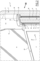
FIG. 2 is a partial perspective cross-sectional view offigure 1 , as outline in bow II-II ofFIG.1 . -
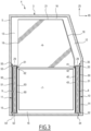
FIG. 3 is a face cross-sectional view similar toFIG.2 , showing the entire vehicle door. -
FIG. 4 is a view similar toFIG.3 , where a mobile window is in an intermediate position. -
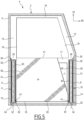
FIG. 5 is a view similar toFIG.3 andFIG. 4 , where a mobile window is in an open position. - Aspects set forth below represent the necessary information to enable those skilled in the art to practice the disclosure.
- The disclosure proposes to improve a driver's visibility and/or to reduce the flowing of water along an area of a ground vehicle to be avoided, such as a side window of the ground vehicle.
-
FIG. 1 shows a ground vehicle 1 inbox 1A. The vehicle 1 includes acab 2 with awindow assembly 3, here belonging to alateral door 4. Thewindow assembly 3 comprises aframe 5, amobile window 6 and afixed window 7. Thedoor 4 may be used by a driver and/or a passenger to enter and exit thecab 2. Thewindows cab 2 may see the surroundings outside of the vehicle 1 through thewindows - The vehicle 1 is here embodied as a truck, i.e. a heavy-duty ground vehicle. However, the vehicle 1 could be another heavy-duty ground vehicle, such as a coach, a bus or a van. The vehicle 1 could even be another type of vehicle that would require a window assembly such as the
window assembly 3, including themobile window 6. - As shown in
FIG.1 , thewindow assembly 3 belongs to thedoor 4. In other embodiments, instead of belonging to thedoor 4, thewindow assembly 3 could belong to a fixed part of a body of the vehicle, belonging to thecab 2. - The
door 4, including thewindow assembly 3, are shown in greater detail in the main view ofFIG. 1 . - The
window assembly 3 comprises theframe 5, themobile window 6, the fixedwindow 7, afirst drive 8, asecond drive 9, afirst transmission mechanism 10 and asecond transmission mechanism 11. - The
window assembly 3 defines a longitudinal direction Z5 and a transversal direction X5, preferably perpendicular to one another, and fixed relative to theframe 5. In use, the longitudinal direction Z5 is preferably oriented upwards, and the transversal direction X5 is preferably oriented substantially horizontally, such as, along the direction of travel of the vehicle 1. - The
frame 5 compriseslongitudinal pillars transversal beams pillars FIG. 1 , thepillar 12. At a first ends thereof, thepillars beam 18. At a second end thereof, thepillars beam 17. At a first ends thereof, thepillars beam 17. At a second end thereof, thepillars beam 16. The second end of thepillar 12 is connected to the first end of thepillar 14, at a first junction with thebeam 17. The second end of thepillar 13 is connected to the first end of thepillar 15, at a second junction with thebeam 17. - The fixed
window 7 is oriented parallel to directions X5 and Z5. The fixedwindow 7 is fixedly attached to theframe 5. The fixedwindow 7 is received between thepillars beams - The
mobile window 6 is oriented parallel to directions X5 and Z5, i.e. parallel to the fixedwindow 7. Themobile window 6 has a firstlongitudinal edge 18, a secondlongitudinal edge 19, a firsttransversal edge 20 and a secondtransversal edge 21. Theedges window 6. The longitudinal edges 18 and 19 are opposite and oriented substantially parallel to direction Z5. Thetransversal edges edge 20 connects theedges edge 21 connects theedges - The
mobile window 6 is mobile relative to theframe 5, by sliding between a closed position shown inFIGS. 1 ,2 and3 and an open position shown inFIG. 5 . When sliding from the closed position to the open position, thewindow 6 is moved in the longitudinal direction Z5, i.e. preferably upwards. When sliding from the open position to the closed position, the window is moved opposite to the longitudinal direction Z5, i.e. preferably downwards. Between the open and closed position, thewindow 6 reaches an intermediate position shown inFIG. 4 . - As visible in
FIGS 1 ,2 and3 , when in the closed position, themobile window 6 is positioned between thebeams pillars mobile window 6 is positioned passed the fixedwindow 7 i.e. is positioned in the direction Z5 relative to the fixedwindow 7. When in the closed position, themobile window 6 closes an opening of theframe 5 delineated by thebeams pillars cab 2 may see the surroundings outside of the vehicle 1 respectively through eachwindow - As visible in
FIG. 5 , when in the open position, themobile window 6 is positioned between thebeams pillars mobile window 6 is superposed with the fixedwindow 7. Thus, a driver and/or a passenger positioned in thecab 2 may see the surroundings outside of the vehicle 1 through thesuperposed windows mobile window 6 leaves open the opening of theframe 5 delineated by thebeams pillars cab 2 may also see the surroundings outside of the vehicle 1 through the opening of theframe 5 left open by thewindow 6. - The
first drive 8 is contained inside thefirst transmission mechanism 10. Thefirst drive 8 andtransmission mechanism 10 are contained in thepillar 14. As best visible inFIGS. 2-5 , thefirst drive 8 comprises afirst rotor 30, afirst stator 31, afirst attachment 32, asecond attachment 33, a firstlongitudinal end 34 and a secondlongitudinal end 35. Thefirst drive 8 defines a first longitudinal axis Z8, parallel to the longitudinal direction Z5 and fixed relative to thestator 31 and theframe 5. - The
longitudinal end 34 is positioned at thebeam 16 and thelongitudinal end 35 is positioned at thebeam 17. - The
first drive 8 may be an electric drive. Thestator 31 has an elongated shape along the axis Z8, and extends from theend 34 to theend 35. Thestator 31 is fixed relative to theframe 5, and is attached to theframe 5 at thefirst end 34, by thefirst attachment 32, and at thesecond end 35, by thesecond attachment 33. Thefirst attachment 32 connects thestator 31 to a junction between thebeam 16 and thepillar 14. Thesecond attachment 33 connects thestator 31 to a junction between thebeam 17 and thepillar 14. - The
rotor 30 has a tubular shape centered on the axis Z8, and extends from theend 34 to theend 35, between theattachments stator 31 is received inside therotor 30, i.e. therotor 30 is arranged around thestator 31. - The
rotor 30 rotates relative to thestator 31, around the axis Z8, when thedrive 8 is electrically powered, i.e. when therotor 30 and/or thestator 31 are electrically powered. Therotor 30 and/or thestator 31 may include electromagnetic windings so that, when electrically powered, therotor 30 is made to rotate relative to thestator 31, i.e. relative to theframe 5, by electromagnetic interaction between therotor 30 and thestator 31. - The sliding of the
mobile window 6 is substantially parallel to the longitudinal axis Z8, since it is parallel to the longitudinal direction Z5. Since thestator 31 is fixed relative to theframe 5, thewindow 6 slides relative to thestator 31. As visible inFIG 5 , in the open position of thewindow 6, thewindow 6 is positioned along thedrive 8, i.e. thetransversal edge 21 of thewindow 6 is positioned at theend 35 of thedrive 8, thetransversal edge 20 is positioned at theend 34 of thedrive 8, thelongitudinal edge 18 is positioned along thedrive 8, and thelongitudinal edge 19 is positioned opposite to thedrive 8. As visible inFIGS 1 ,2 and3 , in the closed position, thewindow 6 is positioned passed thedrive 8 in the direction Z5, i.e. thetransversal edge 21 of thewindow 6 is positioned passed theend 35 in the direction Z5, thetransversal edge 20 is positioned at theend 35 of thedrive 8 and thelongitudinal edge 18 is positioned passed thedrive 8 in the direction Z5. - Since the fixed
window 7 is fixed relative to theframe 5, it is also fixed relative to thestator 31. The fixedwindow 7 is positioned along thefirst drive 8. - The
mobile window 6 is driven between the open position and the closed position by the rotation of therotor 30, via thefirst transmission mechanism 10. To this end, thetransmission mechanism 11 preferably comprises alead screw 40, anut 41, aslider 42 and a slidingguide 43. - The
lead screw 40 is centered on the axis Z8 and is arranged around therotor 30, i.e. therotor 30 is received inside thelead screw 40. Thelead screw 40 is secured to therotor 30, so that thelead screw 40 and therotor 30 rotate together around the axis Z8 relative to thestator 31, when thedrive 8 is powered. Thelead screw 40 extends from theend 34 to theend 35 of thedrive 8. Thelead screw 40 is threaded outwardly. - The
nut 41 is secured to theslider 42. Theslider 42 is secured to themobile window 6, so that thenut 41 is secured to themobile window 6 via theslider 42. Thenut 41 is geared with thelead screw 40 so that theslider 42 and thenut 41 are moved in translation along the axis Z8, between theends lead screw 40 caused by rotation of therotor 30. - The sliding
guide 43 is tubular shaped, centered on axis Z8 and extending from theend 34 to theend 35. The slidingguide 43 is fixedly attached to theframe 5 by theattachments frame 5 and thestator 31. The slidingguide 43 is arranged around thelead screw 40, thus enclosing thelead screw 40 and therotor 30 andstator 31 contained therein. The slidingguide 43 comprises a longitudinal slot, extending from theend 34 to theend 35. Theguide 43 receives theslider 42, which crosses said slot radially relative to the axis Z8. Theslider 42, being received in the slot of theguide 43, is guided by theguide 43 along the axis Z8. Thus, theslider 42 and thenut 41 are prevented from rotating around the axis Z8. Thanks to this arrangement, the sliding of thewindow 6 is guided by theslider 42 and guide 43, and driven by thedrive 8 through thelead screw 40 andnut 41. - The
second drive 9 andtransmission mechanism 11 may be, overall, similar to thefirst drive 8 andtransmission mechanism 10, and positioned at an opposite side of thewindow assembly 3. - The
second drive 9 is contained inside thesecond transmission mechanism 11. Thesecond drive 9 andtransmission mechanism 11 are contained in thepillar 15, opposite to thepillar 14 containing thefirst drive 8 andfirst transmission mechanism 10. As best visible inFIGS. 3-5 , thesecond drive 9 comprises asecond rotor 50, asecond stator 51, afirst attachment 52, asecond attachment 53, a firstlongitudinal end 54 and a secondlongitudinal end 55. Thesecond drive 9 defines a second longitudinal axis Z9, parallel to the longitudinal direction Z5 and fixed relative to thestator 51 and theframe 5. - The
longitudinal end 54 is positioned at thebeam 16 and thelongitudinal end 55 is positioned at thebeam 17. The fixedwindow 7 is positioned along thesecond drive 9, i.e. between thedrives - The
second drive 9 may be an electric drive. Thestator 51 has an elongated shape along the axis Z9, and extends from theend 54 to theend 55. Thestator 51 is fixed relative to theframe 5, and is attached to theframe 5 at thefirst end 54, by thefirst attachment 52, and at thesecond end 55, by thesecond attachment 53. Thefirst attachment 52 connects thestator 51 to a junction between thebeam 16 and thepillar 15. Thesecond attachment 53 connects thestator 51 to a junction between thebeam 17 and thepillar 15. - The
rotor 50 has a tubular shape centered on the axis Z9, and extends from theend 54 to theend 55, between theattachments stator 51 is received inside therotor 50, i.e. therotor 50 is arranged around thestator 31. - The
rotor 50 rotates relative to thestator 51, around the axis Z8, when thedrive 8 is electrically powered, i.e. when therotor 50 and/or thestator 51 are electrically powered. Therotor 50 and/or thestator 51 may include electromagnetic windings so that, when electrically powered, therotor 50 is made to rotate relative to thestator 51, i.e. relative to theframe 5, by electromagnetic interaction between therotor 50 and thestator 51. - As visible in
FIG 5 , in the open position of thewindow 6, thewindow 6 is positioned along thedrive 9, in particular between thedrives transversal edge 21 of thewindow 6 is positioned at theend 55 of thedrive 9, thetransversal edge 20 is positioned at theend 54 of thedrive 9, thelongitudinal edge 19 is positioned along thedrive 9, and thelongitudinal edge 18 is positioned opposite to thedrive 9. As visible inFIGS 1 and3 , in the closed position, thewindow 6 is positioned passed thedrive 9 in the direction Z5, i.e. thetransversal edge 21 of thewindow 6 is positioned passed theend 55 in the direction Z5, thetransversal edge 20 is positioned at theend 55 of thedrive 9 and thelongitudinal edge 19 is positioned passed thedrive 9 in the direction Z5. - The
mobile window 6 is driven between the open position and the closed position by the rotation of therotor 50, via thesecond transmission mechanism 11. To this end, thetransmission mechanism 11 preferably comprises alead screw 60, anut 61, aslider 62 and a slidingguide 63. Thus, thewindow 6 is driven under rotation of bothrotors - The
lead screw 60 is centered on the axis Z9 and is arranged around therotor 50, i.e. therotor 50 is received inside thelead screw 60. Thelead screw 60 is secured to therotor 50, so that thelead screw 60 and therotor 50 rotate together around the axis Z9 relative to thestator 51, when thedrive 9 is powered. Thelead screw 60 extends from theend 54 to theend 55 of thedrive 9. Thelead screw 60 is threaded outwardly. - The
nut 61 is secured to theslider 62. Theslider 62 is secured to themobile window 6, so that thenut 61 is secured to themobile window 6 via theslider 62. Thenut 61 is geared with thelead screw 60 so that theslider 62 and thenut 61 are moved in translation along the axis Z9, between theends lead screw 60 caused by rotation of therotor 50. - The sliding
guide 63 is tubular shaped, centered on axis Z9 and extending from theend 54 to theend 55. The slidingguide 63 is fixedly attached to theframe 5 by theattachments frame 5 and thestator 51. The slidingguide 63 is arranged around thelead screw 60, thus enclosing thelead screw 60 and therotor 50 andstator 51 contained therein. The slidingguide 63 comprises a longitudinal slot, extending from theend 54 to theend 55. Theguide 63 receives theslider 62, which crosses said slot radially relative to the axis Z9. Theslider 62, being received in the slot of theguide 63, is guided by theguide 63 along the axis Z9. Thus, theslider 62 and thenut 61 are prevented from rotating around the axis Z9. Thanks to this arrangement, the sliding of thewindow 6 is guided by bothsliders drives nuts - In an alternative embodiment, the
second drive 9, thenut 61 and thelead screw 60 are omitted, so that thewindow 6 is driven solely by thedrive 8 via thetransmission mechanism 10, and guided by thetransmission mechanism 10 and theslider 62 and slidingguide 63. - In an alternative embodiment, a second mobile window, or another feature than a window, may be provided instead of the fixed
window 7, taking advantage of the space available between thedrives drive 8 if only drive 8 is implemented. - The terminology used herein is for the purpose of describing particular aspects only and is not intended to be limiting of the disclosure. As used herein, the singular forms "a," "an," and "the" are intended to include the plural forms as well, unless the context clearly indicates otherwise. As used herein, the term "and/or" includes any and all combinations of one or more of the associated listed items. It will be further understood that the terms "comprises," "comprising," "includes," and/or "including" when used herein specify the presence of stated features, integers, steps, operations, elements, and/or components, but do not preclude the presence or addition of one or more other features, integers, steps, operations, elements, components, and/or groups thereof.
- It will be understood that, although the terms first, second, etc., may be used herein to describe various elements, these elements should not be limited by these terms. These terms are only used to distinguish one element from another. For example, a first element could be termed a second element, and, similarly, a second element could be termed a first element without departing from the scope of the present disclosure.
- Relative terms such as "below" or "above" or "upper" or "lower" or "horizontal" or "vertical" may be used herein to describe a relationship of one element to another element as illustrated in the Figures. It will be understood that these terms and those discussed above are intended to encompass different orientations of the device in addition to the orientation depicted in the Figures. It will be understood that when an element is referred to as being "connected" or "coupled" to another element, it can be directly connected or coupled to the other element, or intervening elements may be present. In contrast, when an element is referred to as being "directly connected" or "directly coupled" to another element, there are no intervening elements present.
- Unless otherwise defined, all terms (including technical and scientific terms) used herein have the same meaning as commonly understood by one of ordinary skill in the art to which this disclosure belongs. It will be further understood that terms used herein should be interpreted as having a meaning consistent with their meaning in the context of this specification and the relevant art and will not be interpreted in an idealized or overly formal sense unless expressly so defined herein.
- It is to be understood that the present disclosure is not limited to the aspects described above and illustrated in the drawings; rather, the skilled person will recognize that many changes and modifications may be made within the scope of the present disclosure and appended claims. In the drawings and specification, there have been disclosed aspects for purposes of illustration only and not for purposes of limitation, the scope of the inventive concepts being set forth in the following claims.
Claims (9)
- A window assembly (3) for a vehicle (1), the window assembly (3) comprising:- a first drive (8), comprising a first stator (31) and a first rotor (30), the first rotor (30) being arranged around the first stator (31) for rotating relative to the first stator (31), about a first longitudinal axis (Z8) fixed relative to the first stator (31), when the first drive (8) is electrically powered;- a mobile window (6), having a transversal edge (20) and a first longitudinal edge (18), the mobile window (6) being configured for sliding relative to the first stator (31) substantially parallel to the first longitudinal axis (Z8), between an open position where the transversal edge (20) is positioned at a first longitudinal end (34) of the first drive (8) and the first longitudinal edge (18) is positioned along the first drive (8), and a closed position where the transversal edge (20) is positioned at a second longitudinal end (35) of the first drive (8) and where the first longitudinal edge (18) is positioned passed the first drive (8) along the first longitudinal axis (Z8); and- a first transmission mechanism (10), the mobile window (6) being driven between the open position and the closed position by the rotation of the first rotor (30), via the first transmission mechanism (10).
- The window assembly (3) according to claim 1, further comprising a fixed window (7), fixed relative to the first stator (31) and positioned along the first drive (8), wherein the mobile window (6) is superposed with the fixed window (7) when the mobile window (6) is in the open position and wherein the mobile window (6) is positioned passed the fixed window (7) when the mobile window (6) is in the closed position.
- The window assembly (3) according to any one of the preceding claims, wherein the first drive (8) comprises:- a first attachment (32), for attaching the first stator (31) to a frame (5) of the window assembly (3), the mobile window (6) being mobile relative to the frame (5) between the closed and the open position, the first attachment (32) being positioned at the first longitudinal end (34) of the first drive (8), and- a second attachment (33), for attaching the first stator (31) to the frame (5), the second attachment (33) being positioned at a second longitudinal end (35) of the first drive (8), opposite to the first longitudinal end (34) of the first drive (8), the first rotor (30) being arranged between the first attachment (32) and the second attachment (33).
- The window assembly (3) according to any one of the preceding claims, wherein the first transmission mechanism (10) comprises:- a lead screw (40), arranged around the first rotor (30) and secured to the first rotor (30); and- a nut (41), secured to the mobile window (6) and geared with the lead screw (40).
- The window assembly (3) according to any one of the preceding claims, wherein the first transmission mechanism (10) comprises a slider (42), attached to the mobile window (6), and a sliding guide (43), fixed relative to the first stator (31), the slider (42) being guided by the sliding guide (43) for guiding the sliding of the mobile window (6) between the open position and the closed position.
- The window assembly (3) according to any one of the preceding claims, further comprising:- a second drive (9), comprising a second stator (51) and a second rotor (50), the second rotor (50) being arranged around the second stator (51) for rotating relative to the second stator (51), about a second longitudinal axis (Z9) fixed relative to the second stator (51) and parallel to the first longitudinal axis (Z8), when the second drive (9) is electrically powered, the mobile window (6) having a second longitudinal edge (19) opposite to the first longitudinal edge (18), the transversal edge (20) connecting the first longitudinal edge (18) to the second longitudinal edge (19), the transversal edge (20) being positioned at a first longitudinal end (54) of the second drive (9) when the mobile window (6) is in the open position, the second longitudinal edge (19) being positioned along the second drive (9) when the mobile window (6) is in the open position, the second longitudinal edge (19) being positioned passed the second drive (9) along the second longitudinal axis (Z9) when the mobile window (6) is in the closed position; and- a second transmission mechanism (11), the mobile window (6) being driven between the open position and the closed position by rotation of the second rotor (50), via the second transmission mechanism (11), in addition to being driven by rotation of the first rotor (30).
- A vehicle door (4), comprising the window assembly (3) according to any one of the preceding claims.
- A vehicle (1), comprising a cab (2), wherein the cab (2) comprises the window assembly (3) according to any one of claims 1 to 6.
- The vehicle (1) according to claim 8, wherein the vehicle (1) is a heavy-duty ground vehicle.
Priority Applications (2)
| Application Number | Priority Date | Filing Date | Title |
|---|---|---|---|
| EP22191036.7A EP4325016B1 (en) | 2022-08-18 | 2022-08-18 | Window assembly, vehicle door and vehicle |
| US18/360,557 US12173548B2 (en) | 2022-08-18 | 2023-07-27 | Window assembly, vehicle door, and vehicle |
Applications Claiming Priority (1)
| Application Number | Priority Date | Filing Date | Title |
|---|---|---|---|
| EP22191036.7A EP4325016B1 (en) | 2022-08-18 | 2022-08-18 | Window assembly, vehicle door and vehicle |
Publications (2)
| Publication Number | Publication Date |
|---|---|
| EP4325016A1 true EP4325016A1 (en) | 2024-02-21 |
| EP4325016B1 EP4325016B1 (en) | 2025-08-20 |
Family
ID=83004762
Family Applications (1)
| Application Number | Title | Priority Date | Filing Date |
|---|---|---|---|
| EP22191036.7A Active EP4325016B1 (en) | 2022-08-18 | 2022-08-18 | Window assembly, vehicle door and vehicle |
Country Status (2)
| Country | Link |
|---|---|
| US (1) | US12173548B2 (en) |
| EP (1) | EP4325016B1 (en) |
Families Citing this family (1)
| Publication number | Priority date | Publication date | Assignee | Title |
|---|---|---|---|---|
| EP4325016B1 (en) * | 2022-08-18 | 2025-08-20 | Volvo Truck Corporation | Window assembly, vehicle door and vehicle |
Citations (3)
| Publication number | Priority date | Publication date | Assignee | Title |
|---|---|---|---|---|
| US20020092239A1 (en) * | 2001-01-16 | 2002-07-18 | Meritor Light Vehicle Technology, Llc | Window lift mechanism |
| US6655092B2 (en) * | 2000-07-24 | 2003-12-02 | Thyssenkrupp Budd Company | Method for fabricating a vehicle door |
| GB2509606A (en) * | 2013-12-06 | 2014-07-09 | Daimler Ag | A window lifter for a vehicle window |
Family Cites Families (27)
| Publication number | Priority date | Publication date | Assignee | Title |
|---|---|---|---|---|
| US1823237A (en) * | 1927-03-05 | 1931-09-15 | Tropic Aire Inc | Vehicle storm sash |
| US1835174A (en) * | 1929-03-21 | 1931-12-08 | Paul J Osborne | Vehicle window |
| US2150829A (en) * | 1938-05-28 | 1939-03-14 | Grishkevich Max | Adjustable screen and window for automobiles |
| US4331359A (en) * | 1979-12-12 | 1982-05-25 | Skipura Enterprises, Inc. | Window shield for vehicle body |
| SE8602333L (en) * | 1986-05-22 | 1987-11-23 | Autopart Sweden Ab | SUNSHIELD FOR VEHICLE SIDE WINDOW |
| US4930255A (en) * | 1989-05-23 | 1990-06-05 | Sea Ho T | Door window assembly |
| DE4033949C1 (en) * | 1990-10-25 | 1992-01-02 | Vegla Vereinigte Glaswerke Gmbh, 5100 Aachen, De | |
| US5165188A (en) * | 1992-01-08 | 1992-11-24 | Tsiros George N | Adjustable window tinting apparatus |
| US5605013A (en) * | 1995-01-17 | 1997-02-25 | Hogston; Timothy W. | Programmable automatic window |
| GB9822384D0 (en) * | 1998-10-14 | 1998-12-09 | Gray Nigel J | Vehicle security |
| US6415550B1 (en) * | 2000-02-04 | 2002-07-09 | Meritor Light Vehicle Systems, Inc. | Integral linear motor |
| US6430872B1 (en) * | 2000-08-09 | 2002-08-13 | Meritor Light Vehicle Technology, Llc | Position and speed determination for moving glass panel |
| US6523880B1 (en) * | 2001-06-27 | 2003-02-25 | Maher C. Yako | Car window and sunscreen assembly |
| US20030025354A1 (en) * | 2001-08-06 | 2003-02-06 | Femi Akintan | Vehicular window covering |
| US20040003544A1 (en) * | 2002-07-02 | 2004-01-08 | Cooper Technology Services, Llc. | Integral glassrun, glass tracking, and regulator system with optional integral applique |
| US7797882B2 (en) * | 2003-05-14 | 2010-09-21 | Ford Global Technologies, Llc | Window positioning apparatus |
| JP2007297796A (en) * | 2006-04-28 | 2007-11-15 | Fuji Electric Systems Co Ltd | Mobile drive unit |
| US7603811B2 (en) * | 2006-05-15 | 2009-10-20 | Gm Global Technology Operations, Inc. | Linear motor-actuated automotive power windows |
| US7806461B2 (en) * | 2007-05-01 | 2010-10-05 | Christopher Patterson | Apparatus and method for providing tinted windows |
| DE102009006052B4 (en) | 2009-01-24 | 2021-10-14 | Man Truck & Bus Se | Truck cab |
| EA020159B1 (en) * | 2009-03-24 | 2014-09-30 | Сомюнг Ко., Лтд. | DOOR LOCK |
| US20140375083A1 (en) * | 2013-06-19 | 2014-12-25 | Franklin Tejeda | The Dual (day/night) Power Window system for automobiles, the DPW system |
| US10246928B2 (en) * | 2016-09-23 | 2019-04-02 | Milton Manufacturing Inc. | Armored window drive mechanism and system |
| US10343500B2 (en) * | 2017-03-24 | 2019-07-09 | Ford Global Technologies, Llc | Vehicle window assembly with polarized windowpanes and method of operating same |
| US11628748B2 (en) | 2020-07-08 | 2023-04-18 | Oshkosh Corporation | Visibility enhancements for delivery vehicle |
| DE102021204275B4 (en) * | 2021-04-29 | 2025-09-11 | Bos Gmbh & Co. Kg | Protective device for a window opening of a motor vehicle |
| EP4325016B1 (en) * | 2022-08-18 | 2025-08-20 | Volvo Truck Corporation | Window assembly, vehicle door and vehicle |
-
2022
- 2022-08-18 EP EP22191036.7A patent/EP4325016B1/en active Active
-
2023
- 2023-07-27 US US18/360,557 patent/US12173548B2/en active Active
Patent Citations (3)
| Publication number | Priority date | Publication date | Assignee | Title |
|---|---|---|---|---|
| US6655092B2 (en) * | 2000-07-24 | 2003-12-02 | Thyssenkrupp Budd Company | Method for fabricating a vehicle door |
| US20020092239A1 (en) * | 2001-01-16 | 2002-07-18 | Meritor Light Vehicle Technology, Llc | Window lift mechanism |
| GB2509606A (en) * | 2013-12-06 | 2014-07-09 | Daimler Ag | A window lifter for a vehicle window |
Also Published As
| Publication number | Publication date |
|---|---|
| US12173548B2 (en) | 2024-12-24 |
| EP4325016B1 (en) | 2025-08-20 |
| US20240060354A1 (en) | 2024-02-22 |
Similar Documents
| Publication | Publication Date | Title |
|---|---|---|
| US7891730B2 (en) | Drive unit for at least two movable parts of a vehicle, in particular a roof assembly thereof | |
| US6550839B2 (en) | Vehicle pivoting closure power operating assembly | |
| US6170199B1 (en) | Motor vehicle door | |
| US4119341A (en) | Rear window assembly for a truck cab | |
| US6783169B1 (en) | Cover assembly for a vehicle bed | |
| EP1467880B1 (en) | A swing and slide door | |
| US8474186B2 (en) | Direct drive slider window assembly | |
| EP0936092B1 (en) | Vehicle door | |
| US7185943B2 (en) | Two piece sliding window panel having lead screw power unit | |
| US8794690B1 (en) | Pickup truck bed cover | |
| US12173548B2 (en) | Window assembly, vehicle door, and vehicle | |
| EP1275538A1 (en) | Multi-segment lowerable rear window for vehicle | |
| US9771010B2 (en) | Driving device for vertically movable waist bar of vehicle | |
| EP1270298B1 (en) | Roof assembly for a vehicle with a blind attached to the sliding roof panel | |
| US20250018875A1 (en) | Roof module for forming a vehicle roof and motor vehicle with a roof module | |
| US20020092239A1 (en) | Window lift mechanism | |
| ES2270488T5 (en) | SLIDING ROOF SYSTEM WITH WIND DEFLECTOR OF A CAR. | |
| DE19802477A1 (en) | Door module for motor vehicle with external chord window raising mechanism | |
| WO1982003105A1 (en) | Automobile window structure | |
| US6867562B2 (en) | Control system and method for movement of window panes in convertibles | |
| EP0530867B1 (en) | Motor vehicle having an open roof construction and open roof construction to for use in a motor vehicle | |
| CN223778450U (en) | Turbulent flow structure, vehicle body structure and vehicle | |
| US11760173B2 (en) | Safari glass | |
| CN219711295U (en) | Door plate opening and closing device and container | |
| US20230064971A1 (en) | Pulley connector bracket for window regulator systems |
Legal Events
| Date | Code | Title | Description |
|---|---|---|---|
| PUAI | Public reference made under article 153(3) epc to a published international application that has entered the european phase |
Free format text: ORIGINAL CODE: 0009012 |
|
| STAA | Information on the status of an ep patent application or granted ep patent |
Free format text: STATUS: THE APPLICATION HAS BEEN PUBLISHED |
|
| AK | Designated contracting states |
Kind code of ref document: A1 Designated state(s): AL AT BE BG CH CY CZ DE DK EE ES FI FR GB GR HR HU IE IS IT LI LT LU LV MC MK MT NL NO PL PT RO RS SE SI SK SM TR |
|
| STAA | Information on the status of an ep patent application or granted ep patent |
Free format text: STATUS: REQUEST FOR EXAMINATION WAS MADE |
|
| 17P | Request for examination filed |
Effective date: 20240819 |
|
| RBV | Designated contracting states (corrected) |
Designated state(s): AL AT BE BG CH CY CZ DE DK EE ES FI FR GB GR HR HU IE IS IT LI LT LU LV MC MK MT NL NO PL PT RO RS SE SI SK SM TR |
|
| GRAP | Despatch of communication of intention to grant a patent |
Free format text: ORIGINAL CODE: EPIDOSNIGR1 |
|
| STAA | Information on the status of an ep patent application or granted ep patent |
Free format text: STATUS: GRANT OF PATENT IS INTENDED |
|
| INTG | Intention to grant announced |
Effective date: 20250324 |
|
| GRAS | Grant fee paid |
Free format text: ORIGINAL CODE: EPIDOSNIGR3 |
|
| GRAA | (expected) grant |
Free format text: ORIGINAL CODE: 0009210 |
|
| STAA | Information on the status of an ep patent application or granted ep patent |
Free format text: STATUS: THE PATENT HAS BEEN GRANTED |
|
| AK | Designated contracting states |
Kind code of ref document: B1 Designated state(s): AL AT BE BG CH CY CZ DE DK EE ES FI FR GB GR HR HU IE IS IT LI LT LU LV MC MK MT NL NO PL PT RO RS SE SI SK SM TR |
|
| REG | Reference to a national code |
Ref country code: GB Ref legal event code: FG4D |
|
| REG | Reference to a national code |
Ref country code: CH Ref legal event code: EP |
|
| REG | Reference to a national code |
Ref country code: DE Ref legal event code: R096 Ref document number: 602022019694 Country of ref document: DE |
|
| REG | Reference to a national code |
Ref country code: IE Ref legal event code: FG4D |
|
| REG | Reference to a national code |
Ref country code: NL Ref legal event code: MP Effective date: 20250820 |
|
| PG25 | Lapsed in a contracting state [announced via postgrant information from national office to epo] |
Ref country code: IS Free format text: LAPSE BECAUSE OF FAILURE TO SUBMIT A TRANSLATION OF THE DESCRIPTION OR TO PAY THE FEE WITHIN THE PRESCRIBED TIME-LIMIT Effective date: 20251220 |
|
| PG25 | Lapsed in a contracting state [announced via postgrant information from national office to epo] |
Ref country code: NO Free format text: LAPSE BECAUSE OF FAILURE TO SUBMIT A TRANSLATION OF THE DESCRIPTION OR TO PAY THE FEE WITHIN THE PRESCRIBED TIME-LIMIT Effective date: 20251120 |
|
| REG | Reference to a national code |
Ref country code: LT Ref legal event code: MG9D |
|
| PG25 | Lapsed in a contracting state [announced via postgrant information from national office to epo] |
Ref country code: PT Free format text: LAPSE BECAUSE OF FAILURE TO SUBMIT A TRANSLATION OF THE DESCRIPTION OR TO PAY THE FEE WITHIN THE PRESCRIBED TIME-LIMIT Effective date: 20251222 |
|
| PG25 | Lapsed in a contracting state [announced via postgrant information from national office to epo] |
Ref country code: FI Free format text: LAPSE BECAUSE OF FAILURE TO SUBMIT A TRANSLATION OF THE DESCRIPTION OR TO PAY THE FEE WITHIN THE PRESCRIBED TIME-LIMIT Effective date: 20250820 |
|
| PG25 | Lapsed in a contracting state [announced via postgrant information from national office to epo] |
Ref country code: NL Free format text: LAPSE BECAUSE OF FAILURE TO SUBMIT A TRANSLATION OF THE DESCRIPTION OR TO PAY THE FEE WITHIN THE PRESCRIBED TIME-LIMIT Effective date: 20250820 Ref country code: HR Free format text: LAPSE BECAUSE OF FAILURE TO SUBMIT A TRANSLATION OF THE DESCRIPTION OR TO PAY THE FEE WITHIN THE PRESCRIBED TIME-LIMIT Effective date: 20250820 |
|
| PG25 | Lapsed in a contracting state [announced via postgrant information from national office to epo] |
Ref country code: GR Free format text: LAPSE BECAUSE OF FAILURE TO SUBMIT A TRANSLATION OF THE DESCRIPTION OR TO PAY THE FEE WITHIN THE PRESCRIBED TIME-LIMIT Effective date: 20251121 |
|
| PG25 | Lapsed in a contracting state [announced via postgrant information from national office to epo] |
Ref country code: SE Free format text: LAPSE BECAUSE OF FAILURE TO SUBMIT A TRANSLATION OF THE DESCRIPTION OR TO PAY THE FEE WITHIN THE PRESCRIBED TIME-LIMIT Effective date: 20250820 |
|
| PG25 | Lapsed in a contracting state [announced via postgrant information from national office to epo] |
Ref country code: LV Free format text: LAPSE BECAUSE OF FAILURE TO SUBMIT A TRANSLATION OF THE DESCRIPTION OR TO PAY THE FEE WITHIN THE PRESCRIBED TIME-LIMIT Effective date: 20250820 |
|
| PG25 | Lapsed in a contracting state [announced via postgrant information from national office to epo] |
Ref country code: BG Free format text: LAPSE BECAUSE OF FAILURE TO SUBMIT A TRANSLATION OF THE DESCRIPTION OR TO PAY THE FEE WITHIN THE PRESCRIBED TIME-LIMIT Effective date: 20250820 Ref country code: PL Free format text: LAPSE BECAUSE OF FAILURE TO SUBMIT A TRANSLATION OF THE DESCRIPTION OR TO PAY THE FEE WITHIN THE PRESCRIBED TIME-LIMIT Effective date: 20250820 |
|
| PG25 | Lapsed in a contracting state [announced via postgrant information from national office to epo] |
Ref country code: RS Free format text: LAPSE BECAUSE OF FAILURE TO SUBMIT A TRANSLATION OF THE DESCRIPTION OR TO PAY THE FEE WITHIN THE PRESCRIBED TIME-LIMIT Effective date: 20251120 |
|
| PG25 | Lapsed in a contracting state [announced via postgrant information from national office to epo] |
Ref country code: ES Free format text: LAPSE BECAUSE OF FAILURE TO SUBMIT A TRANSLATION OF THE DESCRIPTION OR TO PAY THE FEE WITHIN THE PRESCRIBED TIME-LIMIT Effective date: 20250820 |
|
| REG | Reference to a national code |
Ref country code: AT Ref legal event code: MK05 Ref document number: 1827466 Country of ref document: AT Kind code of ref document: T Effective date: 20250820 |
|
| PG25 | Lapsed in a contracting state [announced via postgrant information from national office to epo] |
Ref country code: SM Free format text: LAPSE BECAUSE OF FAILURE TO SUBMIT A TRANSLATION OF THE DESCRIPTION OR TO PAY THE FEE WITHIN THE PRESCRIBED TIME-LIMIT Effective date: 20250820 |
|
| PG25 | Lapsed in a contracting state [announced via postgrant information from national office to epo] |
Ref country code: DK Free format text: LAPSE BECAUSE OF FAILURE TO SUBMIT A TRANSLATION OF THE DESCRIPTION OR TO PAY THE FEE WITHIN THE PRESCRIBED TIME-LIMIT Effective date: 20250820 |
|
| PG25 | Lapsed in a contracting state [announced via postgrant information from national office to epo] |
Ref country code: AT Free format text: LAPSE BECAUSE OF FAILURE TO SUBMIT A TRANSLATION OF THE DESCRIPTION OR TO PAY THE FEE WITHIN THE PRESCRIBED TIME-LIMIT Effective date: 20250820 |
|
| PG25 | Lapsed in a contracting state [announced via postgrant information from national office to epo] |
Ref country code: IT Free format text: LAPSE BECAUSE OF FAILURE TO SUBMIT A TRANSLATION OF THE DESCRIPTION OR TO PAY THE FEE WITHIN THE PRESCRIBED TIME-LIMIT Effective date: 20250820 |
|
| PG25 | Lapsed in a contracting state [announced via postgrant information from national office to epo] |
Ref country code: CZ Free format text: LAPSE BECAUSE OF FAILURE TO SUBMIT A TRANSLATION OF THE DESCRIPTION OR TO PAY THE FEE WITHIN THE PRESCRIBED TIME-LIMIT Effective date: 20250820 |
|
| PG25 | Lapsed in a contracting state [announced via postgrant information from national office to epo] |
Ref country code: SK Free format text: LAPSE BECAUSE OF FAILURE TO SUBMIT A TRANSLATION OF THE DESCRIPTION OR TO PAY THE FEE WITHIN THE PRESCRIBED TIME-LIMIT Effective date: 20250820 Ref country code: EE Free format text: LAPSE BECAUSE OF FAILURE TO SUBMIT A TRANSLATION OF THE DESCRIPTION OR TO PAY THE FEE WITHIN THE PRESCRIBED TIME-LIMIT Effective date: 20250820 |