EP4324988A1 - Method and system of configuring a machine control unit of a construction machine - Google Patents
Method and system of configuring a machine control unit of a construction machine Download PDFInfo
- Publication number
- EP4324988A1 EP4324988A1 EP22190684.5A EP22190684A EP4324988A1 EP 4324988 A1 EP4324988 A1 EP 4324988A1 EP 22190684 A EP22190684 A EP 22190684A EP 4324988 A1 EP4324988 A1 EP 4324988A1
- Authority
- EP
- European Patent Office
- Prior art keywords
- earth
- moving operation
- operator
- construction machine
- ditch
- Prior art date
- Legal status (The legal status is an assumption and is not a legal conclusion. Google has not performed a legal analysis and makes no representation as to the accuracy of the status listed.)
- Granted
Links
Images


Classifications
-
- E—FIXED CONSTRUCTIONS
- E02—HYDRAULIC ENGINEERING; FOUNDATIONS; SOIL SHIFTING
- E02F—DREDGING; SOIL-SHIFTING
- E02F3/00—Dredgers; Soil-shifting machines
- E02F3/04—Dredgers; Soil-shifting machines mechanically-driven
- E02F3/76—Graders, bulldozers, or the like with scraper plates or ploughshare-like elements; Levelling scarifying devices
-
- E—FIXED CONSTRUCTIONS
- E02—HYDRAULIC ENGINEERING; FOUNDATIONS; SOIL SHIFTING
- E02F—DREDGING; SOIL-SHIFTING
- E02F9/00—Component parts of dredgers or soil-shifting machines, not restricted to one of the kinds covered by groups E02F3/00 - E02F7/00
- E02F9/26—Indicating devices
- E02F9/261—Surveying the work-site to be treated
- E02F9/262—Surveying the work-site to be treated with follow-up actions to control the work tool, e.g. controller
-
- E—FIXED CONSTRUCTIONS
- E01—CONSTRUCTION OF ROADS, RAILWAYS, OR BRIDGES
- E01C—CONSTRUCTION OF, OR SURFACES FOR, ROADS, SPORTS GROUNDS, OR THE LIKE; MACHINES OR AUXILIARY TOOLS FOR CONSTRUCTION OR REPAIR
- E01C19/00—Machines, tools or auxiliary devices for preparing or distributing paving materials, for working the placed materials, or for forming, consolidating, or finishing the paving
- E01C19/004—Devices for guiding or controlling the machines along a predetermined path
-
- E—FIXED CONSTRUCTIONS
- E02—HYDRAULIC ENGINEERING; FOUNDATIONS; SOIL SHIFTING
- E02F—DREDGING; SOIL-SHIFTING
- E02F3/00—Dredgers; Soil-shifting machines
- E02F3/04—Dredgers; Soil-shifting machines mechanically-driven
- E02F3/76—Graders, bulldozers, or the like with scraper plates or ploughshare-like elements; Levelling scarifying devices
- E02F3/7609—Scraper blade mounted forwardly of the tractor on a pair of pivoting arms which are linked to the sides of the tractor, e.g. bulldozers
-
- E—FIXED CONSTRUCTIONS
- E02—HYDRAULIC ENGINEERING; FOUNDATIONS; SOIL SHIFTING
- E02F—DREDGING; SOIL-SHIFTING
- E02F3/00—Dredgers; Soil-shifting machines
- E02F3/04—Dredgers; Soil-shifting machines mechanically-driven
- E02F3/76—Graders, bulldozers, or the like with scraper plates or ploughshare-like elements; Levelling scarifying devices
- E02F3/7636—Graders with the scraper blade mounted under the tractor chassis
- E02F3/765—Graders with the scraper blade mounted under the tractor chassis with the scraper blade being pivotable about a horizontal axis disposed perpendicular to the blade
-
- E—FIXED CONSTRUCTIONS
- E02—HYDRAULIC ENGINEERING; FOUNDATIONS; SOIL SHIFTING
- E02F—DREDGING; SOIL-SHIFTING
- E02F3/00—Dredgers; Soil-shifting machines
- E02F3/04—Dredgers; Soil-shifting machines mechanically-driven
- E02F3/76—Graders, bulldozers, or the like with scraper plates or ploughshare-like elements; Levelling scarifying devices
- E02F3/7663—Graders with the scraper blade mounted under a frame supported by wheels, or the like
- E02F3/7668—Graders with the scraper blade mounted under a frame supported by wheels, or the like with the scraper blade being pivotable about a vertical axis
-
- E—FIXED CONSTRUCTIONS
- E02—HYDRAULIC ENGINEERING; FOUNDATIONS; SOIL SHIFTING
- E02F—DREDGING; SOIL-SHIFTING
- E02F3/00—Dredgers; Soil-shifting machines
- E02F3/04—Dredgers; Soil-shifting machines mechanically-driven
- E02F3/76—Graders, bulldozers, or the like with scraper plates or ploughshare-like elements; Levelling scarifying devices
- E02F3/80—Component parts
- E02F3/84—Drives or control devices therefor, e.g. hydraulic drive systems
-
- E—FIXED CONSTRUCTIONS
- E02—HYDRAULIC ENGINEERING; FOUNDATIONS; SOIL SHIFTING
- E02F—DREDGING; SOIL-SHIFTING
- E02F3/00—Dredgers; Soil-shifting machines
- E02F3/04—Dredgers; Soil-shifting machines mechanically-driven
- E02F3/76—Graders, bulldozers, or the like with scraper plates or ploughshare-like elements; Levelling scarifying devices
- E02F3/80—Component parts
- E02F3/84—Drives or control devices therefor, e.g. hydraulic drive systems
- E02F3/841—Devices for controlling and guiding the whole machine, e.g. by feeler elements and reference lines placed exteriorly of the machine
-
- E—FIXED CONSTRUCTIONS
- E02—HYDRAULIC ENGINEERING; FOUNDATIONS; SOIL SHIFTING
- E02F—DREDGING; SOIL-SHIFTING
- E02F9/00—Component parts of dredgers or soil-shifting machines, not restricted to one of the kinds covered by groups E02F3/00 - E02F7/00
- E02F9/20—Drives; Control devices
-
- E—FIXED CONSTRUCTIONS
- E02—HYDRAULIC ENGINEERING; FOUNDATIONS; SOIL SHIFTING
- E02F—DREDGING; SOIL-SHIFTING
- E02F9/00—Component parts of dredgers or soil-shifting machines, not restricted to one of the kinds covered by groups E02F3/00 - E02F7/00
- E02F9/20—Drives; Control devices
- E02F9/2004—Control mechanisms, e.g. control levers
-
- G—PHYSICS
- G06—COMPUTING OR CALCULATING; COUNTING
- G06T—IMAGE DATA PROCESSING OR GENERATION, IN GENERAL
- G06T7/00—Image analysis
- G06T7/10—Segmentation; Edge detection
- G06T7/13—Edge detection
-
- G—PHYSICS
- G06—COMPUTING OR CALCULATING; COUNTING
- G06T—IMAGE DATA PROCESSING OR GENERATION, IN GENERAL
- G06T7/00—Image analysis
- G06T7/60—Analysis of geometric attributes
-
- G—PHYSICS
- G06—COMPUTING OR CALCULATING; COUNTING
- G06V—IMAGE OR VIDEO RECOGNITION OR UNDERSTANDING
- G06V20/00—Scenes; Scene-specific elements
- G06V20/50—Context or environment of the image
- G06V20/56—Context or environment of the image exterior to a vehicle by using sensors mounted on the vehicle
-
- G—PHYSICS
- G06—COMPUTING OR CALCULATING; COUNTING
- G06T—IMAGE DATA PROCESSING OR GENERATION, IN GENERAL
- G06T2207/00—Indexing scheme for image analysis or image enhancement
- G06T2207/10—Image acquisition modality
- G06T2207/10028—Range image; Depth image; 3D point clouds
Definitions
- the present invention generally relates to a method and system for configuring a machine control unit of a construction machine to control an earth-moving operation that comprises a multitude of phases that are to be performed consecutively, for instance for controlling a motor grader or crawler for ditch or road construction.
- the controlling comprises using 3D sensors to detect a current state of the earth-moving operation in order to configure the machine control unit to at least partially control the construction machine during the next phase of the earth-moving works.
- EP 3 086 196 A1 suggests an environment detection by means of a camera system arranged on a bulldozer.
- the camera system uses a SLAM or SfM algorithm to generate a 3D point cloud of the environment.
- JP 2019 167 719 A2 discloses a 2D laser scanner by means of which a 3D model of the environment is generated when an excavator, on which the 2D scanner is mounted, is pivoting.
- WO 2019/197064 A1 shows a device for monitoring a construction machine environment with a ToF camera. Images generated in such a way are used for guiding an operator of the construction machine in order to control the operation of the construction machine on the construction site according to a plan.
- WO 2020/126123 A2 discloses an example of a compact "reality capture device" comprising a laser scanner and at least one camera. With this reality capture device, an environment can be optically scanned and measured by means of the laser scanner emitting a laser measurement beam, e.g.
- the laser scanner data is combined with camera data, in particular to provide high-resolution spectral information, e.g. by means of an RGB camera or an infrared camera.
- the reality capture device may be mobile and configured to provide surveying data and referencing data at the same time, e.g. wherein at least trajectory data of the device, e.g.
- the reality capture devices can be configured to autonomously create a 3D map of a new environment, e.g. by means of a simultaneous localization and mapping (SLAM) functionality.
- SLAM simultaneous localization and mapping
- the European patent application No. 21176387.5 discloses a similar reality capture device comprising an arrangement of time-of-flight (ToF) cameras instead of a laser scanner, wherein the ToF cameras are configured for jointly capturing 3D point cloud data of the surrounding.
- ToF time-of-flight
- EP 3 865 895 A1 discloses a measurement system for construction machines comprising one or more reality capture devices for capturing surroundings of the construction machine before and during earthmoving works at a construction site.
- Some earth-moving operations comprise a multitude of phases that are to be performed consecutively, wherein the phases are at least partly iterative.
- One example of such an operation is "V-ditching", which is used for construction a ditch with a V-shaped profile. During consecutive passes of the construction machine, the tool is continuously lowered to perform several cuts.
- a first aspect of the invention pertains to a system for configuring a machine control unit of a construction machine for performing an earth-moving operation, the earth-moving operation comprising a multitude of phases that are to be performed consecutively.
- Said system comprises a measuring system configured for capturing three-dimensional measuring data of a terrain in a surrounding of the construction machine in at least a first detection range, a user interface configured for receiving user input from an operator of the construction machine, and a computing unit operatively coupled at least with the measuring system, the user interface and the machine control unit.
- the computing unit is configured for detecting elements of a previous phase of the earth-moving operation based on the three-dimensional measuring data, and, based at least on the detected elements, for configuring the machine control unit to perform the next phase of the earth-moving operation at least partially automatically.
- the measuring system comprises at least one measuring unit at the construction machine, each measuring unit being configured for capturing 3D point cloud data, i.e. as the three-dimensional measuring data.
- Each measuring unit comprises:
- the system comprises a context camera having a known position relative to the measuring system and/or the three-dimensional measuring data and being configured for capturing context image data of the terrain within the first detection range.
- the user interface is configured for displaying at least one context image based on the context image data to an operator of the construction machine
- the computing unit is configured for overlaying the detected elements on the displayed context image and for receiving input from the operator related to a next phase of the earth-moving operation
- configuring the machine control unit is also based on the input from the operator.
- the user interface may comprise a touch-sensitive display on which the context image is displayed and on which the user input is received. The input from the operator for instance may comprise a selection of one or more of the detected elements.
- the construction machine is a motor grader and the earth-moving operation comprises construction a ditch, wherein the phases are passes of the motor grader along a ditch line, including a plurality of cutting passes, and the detected elements comprise an edge and/or surface produced by a previous cutting pass.
- the earth-moving operation may comprise V-ditching.
- the input from the operator may comprise one or more of the following:
- the input from the operator comprises selecting an edge and a surface produced by a previous cutting pass and selecting to adjust a cross slope of the surface for the next pass while maintaining the selected edge as a vertex of a plane to be shaped during the next pass.
- the computing unit is configured for
- the computing unit also may be configured for steering the construction machine to the desired line.
- the operator input comprises an offset of the desired line from a given line and the computing unit is configured to calculate the desired line based on the offset.
- the computing unit may be configured to calculate another spline as the desired line based on the offset.
- the given line may be a line belonging to an existing ditch on a first side of the road, and the desired line is for another ditch to be constructed on the other side of the road, e.g. with the same distance to the road as the ditch on the first side.
- the measuring system is configured for continuously capturing the 3D measuring data and for continuously providing the captured 3D measuring data to the computing unit, wherein the computing unit is configured for continuously evaluating the received 3D measuring data for continuously detecting the elements and for continuously configuring the machine control unit while at least partially automatically performing a phase of the earth-moving operation.
- a second aspect of the invention pertains to a construction machine, e.g. a grader, a dozer or an excavator, the construction machine comprising
- a third aspect of the invention pertains to a computer-implemented method for configuring a machine control unit of a construction machine (e.g. the construction machine according to the second aspect of the invention), for performing an earth-moving operation, the earth-moving operation comprising a multitude of phases that are to be performed consecutively.
- the method comprises the following steps that are performed by a computing unit (e.g. the computing unit of the system according to the first aspect of the invention):
- the method further comprises:
- the construction machine is a motor grader and the earth-moving operation comprises constructing a ditch, for instance by V-ditching.
- the phases are passes of the motor grader along a ditch line, including a plurality of cutting passes, and the detected elements comprise an edge and/or surface produced by a previous cutting pass.
- the input from the operator may then comprise one or more of the following:
- the input from the operator comprises selecting an edge and a surface produced by a previous cutting pass and selecting to adjust a cross slope of the surface for the next pass while maintaining the selected edge as a vertex of a plane to be shaped during the next pass.
- the method further comprises:
- the method may further comprise automatically steering the construction machine to the desired line.
- the operator input comprises an offset of the desired line from a given line and the method comprises calculating the desired line based on the offset.
- the 3D measuring data is captured continuously and evaluated continuously for detecting the elements, and the machine control unit is configured continuously while at least partially automatically performing a phase of the earth-moving operation.
- the earth-moving operation comprises constructing a ditch
- the desired line is a ditch line, e.g. a ditch edge line
- the first phase is a marking pass along the ditch line
- the produced elements produced by the marking pass comprise an edge and/or surface.
- the construction machine may be a motor grader
- the earth-moving operation may comprise V-ditching
- the ditch line may be a ditch edge line, a ditch spline or a ditch edge spline.
- a fourth aspect of the invention pertains to a computer programme product comprising programme code which is stored on a machine-readable medium, or being embodied by an electromagnetic wave comprising a programme code segment, and having computer-executable instructions for performing, particularly when executed on a computing unit of a system according to the first aspect of the invention, the method according to the third aspect of the invention.
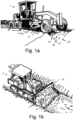
- Figures 1a and 1b show two examples of known construction machines 1 that may be equipped with a system according to the invention.
- Figure 1a shows a motor grader using its tool 11 for digging a V-shaped ditch. This is an iterative process wherein the tool is continuously lowered to perform several cuts. These cuts include an initial light cut as a marking cut 31 and a number of subsequent heavier cuts comprising at least a first cut 32, and a final cut 33.
- Figure 1b shows a crawler (also called bulldozer or dozer) having a blade as a tool 11 for performing earth-moving works, e.g. during road construction. It is known to equip such construction machines 1 with automation systems to facilitate earth-moving operations for the operator by at least partially controlling the machine during these operations.
- grade control systems that can be configured to maintain a desired cross slope. This is a simple functionality that can be used by operators during road construction and ditch construction.
- Typical cross slope systems only control one axis of a tool motion. They act as kinematic constraints, requiring the operator to control a depth of the tool 11, navigate the machine 1, and control other tool motions, e.g. associated with material management.
- FIG 2 illustrates an exemplary method for digging a V-shaped ditch ("V-ditching") using a motor grader as shown in Figure 1a .
- V-ditching a V-shaped ditch
- FIG 1a Such a method is known per se.
- performing this method takes a lot of attention from the operator of the grader since controlling the grader is performed mainly manually.
- Known cross-slope systems may control a single actuator out of the five that are used for blade motion. Disadvantageously, this requires the operator to manage several aspects of blade control while additionally having to navigate the vehicle.
- the operator of a motor grader starts with a light marking cut (see also Figure 1a ) for marking a ditch line.
- the operator may then engage a known 2D cross-slope system, set the system for the desired ditch slope, and then proceed to subsequently make several cutting passes.
- the operator manages the load on the vehicle by adjusting the depth of cut and the angle of the blade.
- the angle of the blade also serves to shift material laterally along the blade and into a windrow.
- a significant windrow has been generated.
- the operator then disengages the cross-slope system and works to first shift the windrow and then spreads it thinly. Additional passes and windrow spreading operations are undertaken until one surface of the ditch is completed.
- the operator can once again engage the 2D cross-slope system while cutting the bank. During these passes, the soil is pushed onto the previously shaped surface. Once the embankment has been shaped, the operator once again clears the material from the ditch using the 2D cross-slope system. The cross-slope system is adjusted for a final surface cut. The windrow is then spread and shaped to the desired height and slope.
- Figures 3a and 3b show a motor grader as an example of a construction machine 1, the grader comprising an exemplary embodiment of system for configuring a machine control unit of the construction machine.
- This system comprises a construction site measuring system with perception sensors which may be included in performing earth-moving operations thus enabling a drastic expansion of the automation used.
- the disclosed method and system provide an extension to existing 2D systems on construction machines, such as crawlers and motor graders. This is based on the addition of perception sensors that add environmental context that existing 2D systems lack.
- the construction machine 1 comprises a tool (blade 11) for performing earthmoving works.
- blade 11 a tool for performing earthmoving works.
- a measuring unit 2 is mounted on a cab 14 of the grader 1 as part of the construction site measuring system.
- the measuring unit 2 comprises one or more reality-capture devices (RCD) 3a, 3b to capture three-dimensional (3D) measuring data of a surrounding (usually uneven) terrain.
- the 3D measuring data - for instance being or comprising a 3D point cloud - is captured in at least one capturing direction.
- this includes a direction towards the front of the construction machine and usually at least partially matches the viewing direction of the operator while operating the machine.
- an RCD in particular comprises some sensor arrangement to capture a 3D point cloud of the environment using a non-contact method.
- this includes determining distances to points in the environment using time-of-flight (ToF) measurements based on light waves (e.g. in the infrared spectrum), radio waves, or ultrasonic sound waves.
- ToF time-of-flight
- stereoscopic vision sensors can provide point-cloud measurements of the environment using disparity, or the difference in position of data in the left and right images.
- each RCD may comprise at least two cameras and optionally other sensors, such as a laser scanner or an arrangement of ToF cameras.
- Reality-capture devices 3a,b of one or more measuring units 2 may be configured to contribute to generating the same 3D point cloud of the terrain, to detect obstacles and/or to track persons or animals entering a danger zone around the machine.
- Measuring units 2 may be provided on many parts of the construction machine, for instance connected to the tool 11, on the chassis 12 and/or on the cab 14.
- the system for configuring the machine control unit comprises a computing unit and a user interface.
- the user interface may be provided at or inside the cab 14 so that it may be used by an operator of the excavator 1 during operation.
- the user interface comprises a display for displaying live images and/or a graphical user interface (GUI).
- GUI graphical user interface
- the user interface comprises a semi-transparent display 4 that is provided in front of the cab 14, allowing the operator to view the displayed content without having to avert his eyes from the terrain ahead.
- the user interface comprises input devices that preferably are provided inside the cab 14 - e.g. comprising a touch-sensitive display (touchscreen) and optionally a stylus for use with the touchscreen.
- the computing unit can use the measuring data generated by the measuring unit (RCD data) - e.g. LiDAR data from a LiDAR scanner and image data from a multitude of cameras - for generating a 3D model, e.g. of the construction site or parts thereof, and optionally also for obstacle detection.
- RCD data generated by the measuring unit
- the computing unit can use the measuring data generated by the measuring unit (RCD data) - e.g. LiDAR data from a LiDAR scanner and image data from a multitude of cameras - for generating a 3D model, e.g. of the construction site or parts thereof, and optionally also for obstacle detection.
- the construction site measuring system additionally may comprise at least one of the following components, which optionally may be provided in a common housing together with the measuring unit 2 or in a common housing together with the computing unit and/or the user interface:
- the image data can be used for colouring the LiDAR data and/or for optimizing a referencing of the LiDAR data by matching them with an image-based generated point cloud (e.g. generated by a visual simultaneous localization and mapping (VSLAM) algorithm).
- VSLAM visual simultaneous localization and mapping
- a feature tracking and/or feature recognition algorithm can help combining the LiDAR data to a consistent and well-referenced global point cloud.
- the position data gained with the GNSS-antenna and the IMU data from the IMU can be used for a sensor fusion to obtain a higher precision when building a 3D model of the terrain.
- a VSLAM point cloud generation can also be supported on LiDAR data, in particular in such a way that the LiDAR data introduce scale and thereby increase stability of the algorithm.
- the LiDAR scanners may be configured for generating the LiDAR data while the two rotation axes of each scanner rotate faster than 0.1 Hz, particularly faster than 1 Hz, with a point acquisition rate of at least 300,000 points per second, particularly at least 500,000 points per second.
- LiDAR scanners - as well as ToF cameras - may be capable to capture a 3D representation of the surrounding at a very fast pace. Therefore, with a moving construction machine it is possible to generate a coherent 3D point cloud based on a SLAM (Simultaneous Localization and Mapping) algorithm that uses the LiDAR data or the ToF data - either alone or in combination with image data from the cameras.
- SLAM Simultaneous Localization and Mapping
- the SLAM algorithm may be supported by at least one IMU providing IMU data that may be processed to stabilize the algorithm. In particular, all such fused sensor data can be processed by a Kalman filter.
- the system for configuring the machine control unit may also comprise at least one context camera, e.g. as a part of the construction site measuring system.
- Said context camera is any camera device that generates an image that provides context of the environment.
- the context camera need not provide any data for use in a sensor system.
- images provided by a stereoscopic camera are suitable for use as a context camera in addition to their use as a sensor through the calculation of a disparity map.
- the context camera may be provided in a common housing together with the RCD 3a,b of the measuring unit 2, at the semi-transparent display 4 or in a common housing together with the computing unit and the user interface.
- the context image data may be related to the RCD data of the construction site measuring system through the use of extrinsic parameters, which characterize the relative position of the context camera and RCDs as they are mounted on the construction machine 1. Images taken by the context camera are displayable to the operator of the machine on the semi-transparent display 4, on a touchscreen and/or on any other display of the user interface, particularly as a live video.
- RCDs 3a,b mounted to the construction machine enables the entire work plan to be localized to the site based on the RCD data. If the RCDs are used for navigation or mapping (e.g. some variant of SLAM), then a design file can be localized to that navigation frame. If the machine is outfitted with GNSS or another global localization system, then the RCD data can be localized to global coordinates and the design file can be localized to the world frame as well. The design file can then be saved and output for reference or later use.
- SLAM navigation or mapping
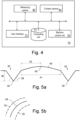
- FIG 4 illustrates an exemplary embodiment of a system 70 according to the invention. It may be provided at least partially on a construction machine, e.g. on the motor grader of Figures 3a and 3b .
- the system 70 comprises a computing unit 71 that is operatively coupled with a user interface 73.
- the user interface is configured to present information to an operator of the system and to receive input from the operator.
- the user interface 73 may be provided in the cab of the excavator of the motor grader of Figures 3a and 3b and comprise a semi-transparent screen and/or a touchscreen.
- the system may further comprise a machine control unit 75 operatively coupled with the computing unit 71.
- the machine control unit 75 is configured to aid the operator in performing earth-moving operations. In particular, this includes at least partially automatically supervising coordinates of a tool of the construction machine, for instance so that the blade of the motor grader of Figures 3a and 3b is prevented from digging below a pre-defined plane.
- the machine control unit 75 may be provided separately on the construction machine and be connectable to the system 70 so that it is operatively coupled with the computing unit 71.
- the system 70 may also comprise one or more reality capture devices (RCD) 82 and at least one context camera 83 that are operatively coupled with the computing unit 71.
- RCD reality capture devices
- An image of the context camera 83 is displayable on a screen, e.g. a touchscreen, of the user interface 73.
- the RCD 82 and context camera 83 may be provided separately on the construction machine and be connectable to the system 70 so that they are operatively coupled with the computing unit 71.
- the computing unit 71 is configured to receive, from the RCD 82, point cloud data of a surface of a construction site, particularly of a surface of the surrounding of the construction machine.
- the computing unit 71 is configured to receive, from the user interface 73, user input regarding a planned earth-moving operation on the construction site.
- the computing unit 71 determines 3D coordinates of the planned earth-moving operation and programmes the machine control unit 75 accordingly.
- Figures 5a shows a final road design in a cross section comprising ditches 30 on both sides of the road crown 40.
- the road and/or the ditches may be constructed using an embodiment of the system according to the invention.
- the road design comprises values for a width 41 and/or half width 42 of a road crown 40.
- values for a ditch depth 36, ditch wall angles 38 and a ditch offset 37 are provided, the ditch offset e.g. describing a distance between the ditch bottom edge 35 and either a road centre 45 or a road edge.
- spline offsetting In order to construct a road with this cross section using the described system, it is necessary for the system to provide for spline offsetting. This allows the operator to use the inner edge of the ditch 30 to define the working direction of the road and then offset the shoulder edge and crown 40 of the road laterally in order to ensure they are parallel to the ditch line.
- the system should also be capable of generating and following curved splines for steering. This is illustrated in Figure 5b , where calculated splines of the ditch edges 35 follow the given spline of the road centre 45.
- a spline of a first ditch edge 35 and of the road may be given, and a spline for a second ditch edge 35 that is to be constructed on the other side of the road is calculated.
- the spline is calculated with an offset so that both ditch edges 35 have the same distance to the road (e.g. to the respective side or to the centre 45 of the road).
- a similar methodology can be used when slot grading with a crawler (as shown in Figure 1b ).
- the operator performs an initial marking cut and then configures the system to maintain the desired slope and navigate along the desired trench.
- the operator is then only responsible for managing vehicle load and shifting it from forward to reverse and vice versa until a windrow spreading operation is necessary.
- a slot grading approach the operator sets a marking line and then uses the system to generate a windrow to either side of the crawler in order to develop a trench. The system then steers between the two windrows.
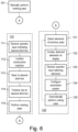
- FIG. 6 is a flow-chart illustrating an exemplary embodiment of a method 100 according to the invention, i.e. a method for configuring a machine control unit of a construction machine for performing an earth-moving operation which comprises a multitude of phases that are to be performed consecutively.
- the earth-moving operation is a V-ditching operation (e.g. as described with respect to Figure 2 )
- the phases are passes of a motor grader or similar machine along a ditch line, the passes including several cutting passes.
- the operator is assisted by an exemplary embodiment of a system according to the invention in performing one or more of these passes.
- a three-dimensional point cloud of a 3D surface is captured, for instance using one or more reality-capture devices (RCD) mounted on a construction machine to capture the surface surrounding the machine.
- RCD reality-capture devices
- the 3D point cloud may be captured continuously.
- a context camera having a known position relative to the 3D point cloud and/or to a measuring system capturing the 3D point cloud captures context image data of the surrounding of the machine.
- the illustrated method starts with performing a marking or registration pass, where the soil is cut just enough to provide a registration line to aid steering on subsequent passes.
- the operator can either perform 101 the marking pass manually, or start an assistance procedure 110 to be assisted by the machine control unit of the construction machine and/or a system according to the invention.
- the operator indicates a desired line for the marking pass ("ditch line"), for instance a straight line or a spline.
- This indication may comprise an input of coordinates or a line drawn in a context image displayed on a touchscreen.
- the operator may select a feature in the context image, e.g. a road or similar structure, and indicate an offset for the desired line from the feature.
- a data file comprising the coordinates can be uploaded to the system.
- the automation system can be set to steer 113 to the desired ditch line and/or set to position 114 the tool, e.g. a toe of a mould board, at the designated ditch line and maintain this position, e.g. at least a height and inclination, while the construction machine follows the ditch line - either steered by the operator, or controlled by the automation system.
- the marking pass is thus performed 115 fully or partly automatically.
- the automation system actuates blade side shift in order to keep the tool, e.g. the toe of the mould board, at the desired position while the operator controls the steering, circle shift and circle angles.
- a following pass can begin, e.g. as shown here a cutting procedure 120 that includes making a first deep cut.
- the construction site measuring system can automatically detect 121 edges and surfaces of the previous pass, i.e. of the marking pass or a previous cutting pass. These edges and surfaces may be detected 121, e.g., in image data and/or point cloud data captured by the RCDs.
- the system can then present these detected elements in a display, for instance by overlaying 122 them in a context image displayed on a touchscreen, and allow the operator to select previously shaped edges and/or surfaces in order to configure the automation systems for a present cutting pass. For instance, the operator can select the edge of the previous cut and configure the system to cut 25 mm below it for the next pass. The operator can select the previous surface and configure the system to maintain a parallel cut for the following pass. The cut might also be intended to change the cross slope of the surface but use the previously sloped edge as a vertex of the plane being shaped on the subsequent cutting pass. These selections are received 123 as operator input on the user interface, e.g. on a touchscreen showing a context image, to configure 124 the automation system for fully or partly automatically performing 125 the cutting pass. This cutting procedure 120 can be repeated until the last pass has been made and the construction of the ditch is completed.
- the input may include a selection of pixels of the context image or be interpreted as such a selection of pixels.
- the selection of pixels e.g. representing a desired ditch line
- the selection of pixels can be mapped to the 3D measuring data, e.g. to a surface of a 3D terrain model that is generated based on the 3D measuring data. Based on the mapping, it is then possible to determine 3D coordinates on the surface that can be provided to the machine control unit for at least partially controlling the earth-moving operation. This is described in detail in the European patent application No. 22180149.1 .
- the data captured by the RCDs can also be used to monitor the shed material as it forms a windrow.
- the volume of material in the windrow or the height of the windrow can be used to indicate to the operator when it is necessary to perform a spreading pass (see e.g. steps 7 and 8 in Figure 2 ).
- the control unit may be triggered to perform a spreading behaviour during the next pass or to automatically perform a spreading pass.
- the method may include storing information regarding previously identified lines and surfaces in a memory and retrieving this information in a subsequent pass.
- the method may comprise passes for cleaning a bottom of a ditch (see e.g. steps 9 and 10 in Figure 2 ).
- the method may comprise passes for cleaning a bottom of a ditch (see e.g. steps 9 and 10 in Figure 2 ).
- the system remembers the location of the bottom edge of the ditch even when it is covered in soil. This would allow the operator to cut the inside slope of the ditch and then use the inner edge of the ditch when cutting the outer slope of the ditch and then again when clearing the soil out of the bottom of the ditch.
- the system may be configured to self-configure.
- the operator may set the cross-slope and height for the marking pass, incrementing the height until the correct depth is reached for a marking pass.
- the localization capability of the RCDs enables a globally consistent height to be maintained as the vehicle navigates the site. The operator can then use an increment button to tell the system the desired depth of each cutting pass.
- the construction site measuring system can use its localization capabilities to determine when it was at the beginning position of the job. It can then combine the localization data with the configuration for the previous cutting pass in order to automatically detect and identify the edges and surfaces cut by the machine. It can then automatically set the desired steering spline or mould-board toe line based on the previous pass and operator indicated depth.
- a method and system according to the invention can also be used to monitor the construction of a V-ditch. Since the system knows the workflow, it can be used to track the steps used in the construction as well as the system configuration and work product for each pass. This data provides a real-time status for the construction job and can also be used to train new operators, using the system to designate the desired workflow for inexperienced operators.
- the system may include a mechanism for sensing a load of the construction machine. This may include sensing engine torque, watching engine speed changes, hydrostatic loop pressures and or displacements, transmission output torque, torque converter torque, etc.
- a depth control of the control unit may be set to a load dependent state where the system can automatically adjust a height of the tool based on the detected load.
Landscapes
- Engineering & Computer Science (AREA)
- Civil Engineering (AREA)
- Structural Engineering (AREA)
- Mining & Mineral Resources (AREA)
- General Engineering & Computer Science (AREA)
- Mechanical Engineering (AREA)
- Physics & Mathematics (AREA)
- Theoretical Computer Science (AREA)
- General Physics & Mathematics (AREA)
- Computer Vision & Pattern Recognition (AREA)
- Architecture (AREA)
- Geometry (AREA)
- Multimedia (AREA)
- Operation Control Of Excavators (AREA)
- Component Parts Of Construction Machinery (AREA)
Abstract
Description
- The present invention generally relates to a method and system for configuring a machine control unit of a construction machine to control an earth-moving operation that comprises a multitude of phases that are to be performed consecutively, for instance for controlling a motor grader or crawler for ditch or road construction. The controlling comprises using 3D sensors to detect a current state of the earth-moving operation in order to configure the machine control unit to at least partially control the construction machine during the next phase of the earth-moving works.
- It is known to use automation systems for construction machines to facilitate earth-moving operations for the operator of the machine by fully or partially controlling the machine. Existing automation systems focus primarily on a final grading pass required to cut the soil surface to the desired profile. There are two primary applications that differ based on whether the desired profile is localized relative to world coordinates ("3D system"), or the desired profile is localized relative to vehicle coordinates ("2D system"). 2D systems are simpler to work with. A soil profile is designed relative to the vehicle system and the operator is fully responsible for navigating the vehicle so that the system generates the correct surface. 3D systems require a surface design file that is created using a complex computer system. The machine can then be localized relative to the 3D plan and the surface cut correctly with a variety of possible navigation motion.
- There are various measuring systems known for the specific needs in the field of construction, especially for earth-moving machines, such as excavators, graders or dozers. Such measuring systems can be used with a construction machine to build a digital 3D model of the surroundings of the machine, to detect obstacles in the surroundings of the machine, and/or to support a control of the construction machine. For example,
EP 3 086 196 A1JP 2019 167 719 A2 WO 2019/197064 A1 shows a device for monitoring a construction machine environment with a ToF camera. Images generated in such a way are used for guiding an operator of the construction machine in order to control the operation of the construction machine on the construction site according to a plan. - Advances in perception sensors allow for a new interactive workflow that enables a 3D design surface to be generated in a simpler manner, resembling that of existing 2D systems. These same perception sensors allow for the machine to localize itself relative to coordinates of a design file and enable advancements in the automation of the machine so that the automation systems can be used in a wider range of operator conditions.
WO 2020/126123 A2 discloses an example of a compact "reality capture device" comprising a laser scanner and at least one camera. With this reality capture device, an environment can be optically scanned and measured by means of the laser scanner emitting a laser measurement beam, e.g. using pulsed electromagnetic radiation, wherein an echo is received from a backscattering surface point of the environment and a distance to the surface point is derived and associated with an angular emission direction of the associated laser measurement beam. This way, a three-dimensional point cloud is generated. For example, the distance measurement may be based on the time of flight, the shape, and/or the phase of the pulse. For additional information, the laser scanner data is combined with camera data, in particular to provide high-resolution spectral information, e.g. by means of an RGB camera or an infrared camera. The reality capture device may be mobile and configured to provide surveying data and referencing data at the same time, e.g. wherein at least trajectory data of the device, e.g. position and/or pose data, are provided with the probing data, e.g. laser scanner data and/or camera data, such that probing data of different positions of the reality capture device can be combined into a common coordinate system. The reality capture devices can be configured to autonomously create a 3D map of a new environment, e.g. by means of a simultaneous localization and mapping (SLAM) functionality. TheEuropean patent application No. 21176387.5 -
EP 3 865 895 A1 - Some earth-moving operations comprise a multitude of phases that are to be performed consecutively, wherein the phases are at least partly iterative. One example of such an operation is "V-ditching", which is used for construction a ditch with a V-shaped profile. During consecutive passes of the construction machine, the tool is continuously lowered to perform several cuts.
- It would be desirable to provide a construction site measuring system for a construction machine that facilitates performing such earth-moving operations for the operator of the construction machine, particularly by allowing a higher grade of automation in the control of the machine.
- It is therefore an object of the present invention to provide an improved system and method for configuring a machine control unit of a construction machine for performing an earth-moving operation.
- It is a further object of the invention to provide such a system and method that allow configuring the machine control unit to perform the earth-moving operation at least partially automatically.
- It is a further object of the invention to provide such a system and method that allow configuring the machine control unit to perform at least a subset of phases of an earth-moving operation that comprising a multitude of phases that are to be performed consecutively.
- At least one of these objects is achieved by the system according to
claim 1, the construction machine according toclaim 8, the computer-implemented method according toclaim 9, the computer programme product according to claim 15 and/or the dependent claims of the present application. - A first aspect of the invention pertains to a system for configuring a machine control unit of a construction machine for performing an earth-moving operation, the earth-moving operation comprising a multitude of phases that are to be performed consecutively. Said system comprises a measuring system configured for capturing three-dimensional measuring data of a terrain in a surrounding of the construction machine in at least a first detection range, a user interface configured for receiving user input from an operator of the construction machine, and a computing unit operatively coupled at least with the measuring system, the user interface and the machine control unit. According to this aspect of the invention, the computing unit is configured for detecting elements of a previous phase of the earth-moving operation based on the three-dimensional measuring data, and, based at least on the detected elements, for configuring the machine control unit to perform the next phase of the earth-moving operation at least partially automatically.
- According to some embodiments of the system, the measuring system comprises at least one measuring unit at the construction machine, each measuring unit being configured for capturing 3D point cloud data, i.e. as the three-dimensional measuring data. Each measuring unit comprises:
- at least one laser scanner,
- a plurality of ToF cameras,
- a millimetre wave radar system, and/or
- one or more stereo camera systems.
- According to some embodiments, the system comprises a context camera having a known position relative to the measuring system and/or the three-dimensional measuring data and being configured for capturing context image data of the terrain within the first detection range. In this case, the user interface is configured for displaying at least one context image based on the context image data to an operator of the construction machine, the computing unit is configured for overlaying the detected elements on the displayed context image and for receiving input from the operator related to a next phase of the earth-moving operation, and configuring the machine control unit is also based on the input from the operator. Optionally, the user interface may comprise a touch-sensitive display on which the context image is displayed and on which the user input is received. The input from the operator for instance may comprise a selection of one or more of the detected elements.
- According to some embodiments, the construction machine is a motor grader and the earth-moving operation comprises construction a ditch, wherein the phases are passes of the motor grader along a ditch line, including a plurality of cutting passes, and the detected elements comprise an edge and/or surface produced by a previous cutting pass. For instance, the earth-moving operation may comprise V-ditching. Optionally, the input from the operator may comprise one or more of the following:
- selecting an edge and/or surface produced by a previous cutting pass;
- selecting a cutting depth for the next pass; and/or
- selecting to maintain a parallel cut for the next pass.
- In one embodiment, the input from the operator comprises selecting an edge and a surface produced by a previous cutting pass and selecting to adjust a cross slope of the surface for the next pass while maintaining the selected edge as a vertex of a plane to be shaped during the next pass.
- According to some embodiments of the system, the computing unit is configured for
- receiving operator input indicating a desired line (for instance a spline), along which line the earth moving operation is desired to be performed,
- localizing the construction machine based on the three-dimensional measuring data, e.g. relative to the desired line,
- positioning the tool at the desired line, and
- performing a first phase of the multitude of phases, thereby producing detectable elements.
- Optionally, the computing unit also may be configured for steering the construction machine to the desired line.
- In some embodiments, the operator input comprises an offset of the desired line from a given line and the computing unit is configured to calculate the desired line based on the offset. For instance, if the given line is a spline, the computing unit may be configured to calculate another spline as the desired line based on the offset. In one example, the given line may be a line belonging to an existing ditch on a first side of the road, and the desired line is for another ditch to be constructed on the other side of the road, e.g. with the same distance to the road as the ditch on the first side.
- According to some embodiments of the system, the measuring system is configured for continuously capturing the 3D measuring data and for continuously providing the captured 3D measuring data to the computing unit, wherein the computing unit is configured for continuously evaluating the received 3D measuring data for continuously detecting the elements and for continuously configuring the machine control unit while at least partially automatically performing a phase of the earth-moving operation.
- A second aspect of the invention pertains to a construction machine, e.g. a grader, a dozer or an excavator, the construction machine comprising
- a tool for performing an earth-moving operation, e.g. for digging a ditch or trench,
- a control unit for at least partially controlling the earth-moving operation, and
- a system according to the first aspect of the invention, the system being operatively coupled with the control unit or comprising the control unit.
- A third aspect of the invention pertains to a computer-implemented method for configuring a machine control unit of a construction machine (e.g. the construction machine according to the second aspect of the invention), for performing an earth-moving operation, the earth-moving operation comprising a multitude of phases that are to be performed consecutively. The method comprises the following steps that are performed by a computing unit (e.g. the computing unit of the system according to the first aspect of the invention):
- receiving 3D measuring data of a terrain in a surrounding of the construction machine in at least a first detection range;
- detecting elements of a previous phase of the earth-moving operation based on the 3D measuring data; and
- configuring, based at least on the detected elements, the machine control unit to at least partially perform the next phase of the earth-moving operation automatically.
- According to some embodiments, the method further comprises:
- capturing context image data of the terrain within the first detection range using a context camera having a known position relative to the 3D measuring data and/or to a measuring system capturing the 3D measuring data;
- displaying at least one context image based on the context image data to an operator of the construction machine, overlaying the detected elements on the displayed context image; and
- receiving input from the operator related to a next phase of the earth-moving operation, particularly wherein the input from the operator comprises a selection of one or more of the detected elements, wherein configuring the machine control unit is also based on the input from the operator.
- According to some embodiments of the method, the construction machine is a motor grader and the earth-moving operation comprises constructing a ditch, for instance by V-ditching. In this case, the phases are passes of the motor grader along a ditch line, including a plurality of cutting passes, and the detected elements comprise an edge and/or surface produced by a previous cutting pass. Optionally, the input from the operator may then comprise one or more of the following:
- selecting an edge and/or surface produced by a previous cutting pass,
- selecting to maintain a parallel cut for the next pass, and/or
- selecting a cutting depth for the next pass.
- In one embodiment, the input from the operator comprises selecting an edge and a surface produced by a previous cutting pass and selecting to adjust a cross slope of the surface for the next pass while maintaining the selected edge as a vertex of a plane to be shaped during the next pass.
- According to some embodiments, the method further comprises:
- receiving operator input indicating a desired line, e.g. a spline, along which line the earth moving operation is desired to be performed,
- localizing the construction machine based on the three-dimensional measuring data, particularly relative to the desired line,
- positioning the tool at the desired line, and
- performing a first phase of the multitude of phases, thereby producing detectable elements.
- Optionally, the method may further comprise automatically steering the construction machine to the desired line. In one embodiment, the operator input comprises an offset of the desired line from a given line and the method comprises calculating the desired line based on the offset.
- According to some embodiments of the method, the 3D measuring data is captured continuously and evaluated continuously for detecting the elements, and the machine control unit is configured continuously while at least partially automatically performing a phase of the earth-moving operation.
- According to some embodiments of the method, the earth-moving operation comprises constructing a ditch, the desired line is a ditch line, e.g. a ditch edge line, the first phase is a marking pass along the ditch line, and the produced elements produced by the marking pass comprise an edge and/or surface. Optionally, the construction machine may be a motor grader, the earth-moving operation may comprise V-ditching, and/or the ditch line may be a ditch edge line, a ditch spline or a ditch edge spline.
- A fourth aspect of the invention pertains to a computer programme product comprising programme code which is stored on a machine-readable medium, or being embodied by an electromagnetic wave comprising a programme code segment, and having computer-executable instructions for performing, particularly when executed on a computing unit of a system according to the first aspect of the invention, the method according to the third aspect of the invention.
- By way of example only, preferred embodiments of the invention will be described more fully hereinafter with reference to the accompanying figures, wherein:
- Figs. 1a-b
- show two exemplary embodiments of known construction machines for performing earth-moving operations;
- Fig. 2
- illustrates an exemplary method for constructing a ditch using a motor grader;
- Figs. 3a-b
- show a motor grader as an example of a construction machine, the grader comprising an exemplary embodiment of a construction site measuring system according to the invention;
- Fig. 4
- shows an exemplary embodiment of a system according to the invention;
- Figs. 5a-b
- show a road design comprising ditches; and
- Fig. 6
- shows a flow chart illustrating steps of exemplary embodiments of a method according to the invention.
-
Figures 1a and 1b show two examples of knownconstruction machines 1 that may be equipped with a system according to the invention.Figure 1a shows a motor grader using itstool 11 for digging a V-shaped ditch. This is an iterative process wherein the tool is continuously lowered to perform several cuts. These cuts include an initial light cut as a marking cut 31 and a number of subsequent heavier cuts comprising at least afirst cut 32, and afinal cut 33.Figure 1b shows a crawler (also called bulldozer or dozer) having a blade as atool 11 for performing earth-moving works, e.g. during road construction. It is known to equipsuch construction machines 1 with automation systems to facilitate earth-moving operations for the operator by at least partially controlling the machine during these operations. - In the
construction machines 1 shown here, i.e. in graders and crawlers, current automation systems often comprise grade control systems that can be configured to maintain a desired cross slope. This is a simple functionality that can be used by operators during road construction and ditch construction. Typical cross slope systems only control one axis of a tool motion. They act as kinematic constraints, requiring the operator to control a depth of thetool 11, navigate themachine 1, and control other tool motions, e.g. associated with material management. -
Figure 2 illustrates an exemplary method for digging a V-shaped ditch ("V-ditching") using a motor grader as shown inFigure 1a . Such a method is known per se. Currently, performing this method takes a lot of attention from the operator of the grader since controlling the grader is performed mainly manually. Known cross-slope systems may control a single actuator out of the five that are used for blade motion. Disadvantageously, this requires the operator to manage several aspects of blade control while additionally having to navigate the vehicle. - The operator of a motor grader starts with a light marking cut (see also
Figure 1a ) for marking a ditch line. The operator may then engage a known 2D cross-slope system, set the system for the desired ditch slope, and then proceed to subsequently make several cutting passes. During these passes the operator manages the load on the vehicle by adjusting the depth of cut and the angle of the blade. The angle of the blade also serves to shift material laterally along the blade and into a windrow. After several cutting passes, a significant windrow has been generated. The operator then disengages the cross-slope system and works to first shift the windrow and then spreads it thinly. Additional passes and windrow spreading operations are undertaken until one surface of the ditch is completed. The operator can once again engage the 2D cross-slope system while cutting the bank. During these passes, the soil is pushed onto the previously shaped surface. Once the embankment has been shaped, the operator once again clears the material from the ditch using the 2D cross-slope system. The cross-slope system is adjusted for a final surface cut. The windrow is then spread and shaped to the desired height and slope. -
Figures 3a and3b show a motor grader as an example of aconstruction machine 1, the grader comprising an exemplary embodiment of system for configuring a machine control unit of the construction machine. This system comprises a construction site measuring system with perception sensors which may be included in performing earth-moving operations thus enabling a drastic expansion of the automation used. The disclosed method and system provide an extension to existing 2D systems on construction machines, such as crawlers and motor graders. This is based on the addition of perception sensors that add environmental context that existing 2D systems lack. - As shown in
Figure 3a , theconstruction machine 1 comprises a tool (blade 11) for performing earthmoving works. Although the shown machine is a motor grader, it could as well be any other construction machine usable in earthmoving works, such as an excavator or a dozer. A measuringunit 2 is mounted on acab 14 of thegrader 1 as part of the construction site measuring system. - As shown in more detail in
Figure 3b , the measuringunit 2 comprises one or more reality-capture devices (RCD) 3a, 3b to capture three-dimensional (3D) measuring data of a surrounding (usually uneven) terrain. The 3D measuring data - for instance being or comprising a 3D point cloud - is captured in at least one capturing direction. Preferably, this includes a direction towards the front of the construction machine and usually at least partially matches the viewing direction of the operator while operating the machine. - In the context of the present invention, an RCD in particular comprises some sensor arrangement to capture a 3D point cloud of the environment using a non-contact method. Typically, this includes determining distances to points in the environment using time-of-flight (ToF) measurements based on light waves (e.g. in the infrared spectrum), radio waves, or ultrasonic sound waves. However, stereoscopic vision sensors can provide point-cloud measurements of the environment using disparity, or the difference in position of data in the left and right images. For instance, each RCD may comprise at least two cameras and optionally other sensors, such as a laser scanner or an arrangement of ToF cameras. Reality-capture devices 3a,b of one or
more measuring units 2 may be configured to contribute to generating the same 3D point cloud of the terrain, to detect obstacles and/or to track persons or animals entering a danger zone around the machine. Measuringunits 2 may be provided on many parts of the construction machine, for instance connected to thetool 11, on thechassis 12 and/or on thecab 14. - The system for configuring the machine control unit comprises a computing unit and a user interface. Preferably, the user interface may be provided at or inside the
cab 14 so that it may be used by an operator of theexcavator 1 during operation. The user interface comprises a display for displaying live images and/or a graphical user interface (GUI). In the exemplary embodiment shown inFigure 3b , the user interface comprises asemi-transparent display 4 that is provided in front of thecab 14, allowing the operator to view the displayed content without having to avert his eyes from the terrain ahead. - The user interface comprises input devices that preferably are provided inside the cab 14 - e.g. comprising a touch-sensitive display (touchscreen) and optionally a stylus for use with the touchscreen. The computing unit can use the measuring data generated by the measuring unit (RCD data) - e.g. LiDAR data from a LiDAR scanner and image data from a multitude of cameras - for generating a 3D model, e.g. of the construction site or parts thereof, and optionally also for obstacle detection.
- The construction site measuring system additionally may comprise at least one of the following components, which optionally may be provided in a common housing together with the measuring
unit 2 or in a common housing together with the computing unit and/or the user interface: - a GNSS-antenna configured for generating position data,
- an Inertial Measurement Unit (IMU) configured for generating IMU data, and
- a cellular unit configured for transmitting any data to a remote station or other vehicles, e.g. construction machines or haul trucks on the same construction site.
- For instance, if the measuring data comprises LiDAR data and image data, the image data can be used for colouring the LiDAR data and/or for optimizing a referencing of the LiDAR data by matching them with an image-based generated point cloud (e.g. generated by a visual simultaneous localization and mapping (VSLAM) algorithm). Also a feature tracking and/or feature recognition algorithm can help combining the LiDAR data to a consistent and well-referenced global point cloud. Similarly, the position data gained with the GNSS-antenna and the IMU data from the IMU can be used for a sensor fusion to obtain a higher precision when building a 3D model of the terrain. A VSLAM point cloud generation can also be supported on LiDAR data, in particular in such a way that the LiDAR data introduce scale and thereby increase stability of the algorithm. The LiDAR scanners may be configured for generating the LiDAR data while the two rotation axes of each scanner rotate faster than 0.1 Hz, particularly faster than 1 Hz, with a point acquisition rate of at least 300,000 points per second, particularly at least 500,000 points per second.
- LiDAR scanners - as well as ToF cameras - may be capable to capture a 3D representation of the surrounding at a very fast pace. Therefore, with a moving construction machine it is possible to generate a coherent 3D point cloud based on a SLAM (Simultaneous Localization and Mapping) algorithm that uses the LiDAR data or the ToF data - either alone or in combination with image data from the cameras. Such localization and mapping is specifically advantageous if the construction machine is operating under a bridge or some other place shadowed from GNSS signals. The SLAM algorithm may be supported by at least one IMU providing IMU data that may be processed to stabilize the algorithm. In particular, all such fused sensor data can be processed by a Kalman filter.
- Optionally, the system for configuring the machine control unit may also comprise at least one context camera, e.g. as a part of the construction site measuring system. Said context camera is any camera device that generates an image that provides context of the environment. In particular, the context camera need not provide any data for use in a sensor system. However, images provided by a stereoscopic camera are suitable for use as a context camera in addition to their use as a sensor through the calculation of a disparity map. The context camera may be provided in a common housing together with the RCD 3a,b of the measuring
unit 2, at thesemi-transparent display 4 or in a common housing together with the computing unit and the user interface. The context image data may be related to the RCD data of the construction site measuring system through the use of extrinsic parameters, which characterize the relative position of the context camera and RCDs as they are mounted on theconstruction machine 1. Images taken by the context camera are displayable to the operator of the machine on thesemi-transparent display 4, on a touchscreen and/or on any other display of the user interface, particularly as a live video. - The use of one or more RCDs 3a,b mounted to the construction machine enables the entire work plan to be localized to the site based on the RCD data. If the RCDs are used for navigation or mapping (e.g. some variant of SLAM), then a design file can be localized to that navigation frame. If the machine is outfitted with GNSS or another global localization system, then the RCD data can be localized to global coordinates and the design file can be localized to the world frame as well. The design file can then be saved and output for reference or later use.
-
Figure 4 illustrates an exemplary embodiment of asystem 70 according to the invention. It may be provided at least partially on a construction machine, e.g. on the motor grader ofFigures 3a and3b . Thesystem 70 comprises acomputing unit 71 that is operatively coupled with auser interface 73. The user interface is configured to present information to an operator of the system and to receive input from the operator. For instance, theuser interface 73 may be provided in the cab of the excavator of the motor grader ofFigures 3a and3b and comprise a semi-transparent screen and/or a touchscreen. - The system may further comprise a
machine control unit 75 operatively coupled with thecomputing unit 71. Themachine control unit 75 is configured to aid the operator in performing earth-moving operations. In particular, this includes at least partially automatically supervising coordinates of a tool of the construction machine, for instance so that the blade of the motor grader ofFigures 3a and3b is prevented from digging below a pre-defined plane. Alternatively, themachine control unit 75 may be provided separately on the construction machine and be connectable to thesystem 70 so that it is operatively coupled with thecomputing unit 71. - The
system 70 may also comprise one or more reality capture devices (RCD) 82 and at least onecontext camera 83 that are operatively coupled with thecomputing unit 71. An image of thecontext camera 83 is displayable on a screen, e.g. a touchscreen, of theuser interface 73. Alternatively, theRCD 82 andcontext camera 83 may be provided separately on the construction machine and be connectable to thesystem 70 so that they are operatively coupled with thecomputing unit 71. - The
computing unit 71 is configured to receive, from theRCD 82, point cloud data of a surface of a construction site, particularly of a surface of the surrounding of the construction machine. Thecomputing unit 71 is configured to receive, from theuser interface 73, user input regarding a planned earth-moving operation on the construction site. Thecomputing unit 71 determines 3D coordinates of the planned earth-moving operation and programmes themachine control unit 75 accordingly. -
Figures 5a shows a final road design in a cross section comprising ditches 30 on both sides of theroad crown 40. The road and/or the ditches may be constructed using an embodiment of the system according to the invention. For instance, the road design comprises values for awidth 41 and/orhalf width 42 of aroad crown 40. Regarding theditches 30, values for aditch depth 36, ditch wall angles 38 and a ditch offset 37 are provided, the ditch offset e.g. describing a distance between theditch bottom edge 35 and either aroad centre 45 or a road edge. - In order to construct a road with this cross section using the described system, it is necessary for the system to provide for spline offsetting. This allows the operator to use the inner edge of the
ditch 30 to define the working direction of the road and then offset the shoulder edge andcrown 40 of the road laterally in order to ensure they are parallel to the ditch line. The system should also be capable of generating and following curved splines for steering. This is illustrated inFigure 5b , where calculated splines of the ditch edges 35 follow the given spline of theroad centre 45. Alternatively, a spline of afirst ditch edge 35 and of the road may be given, and a spline for asecond ditch edge 35 that is to be constructed on the other side of the road is calculated. For instance, the spline is calculated with an offset so that both ditch edges 35 have the same distance to the road (e.g. to the respective side or to thecentre 45 of the road). - A similar methodology can be used when slot grading with a crawler (as shown in
Figure 1b ). The operator performs an initial marking cut and then configures the system to maintain the desired slope and navigate along the desired trench. The operator is then only responsible for managing vehicle load and shifting it from forward to reverse and vice versa until a windrow spreading operation is necessary. In a slot grading approach the operator sets a marking line and then uses the system to generate a windrow to either side of the crawler in order to develop a trench. The system then steers between the two windrows. -
Figure 6 is a flow-chart illustrating an exemplary embodiment of a method 100 according to the invention, i.e. a method for configuring a machine control unit of a construction machine for performing an earth-moving operation which comprises a multitude of phases that are to be performed consecutively. In the example described here, the earth-moving operation is a V-ditching operation (e.g. as described with respect toFigure 2 ), and the phases are passes of a motor grader or similar machine along a ditch line, the passes including several cutting passes. The operator is assisted by an exemplary embodiment of a system according to the invention in performing one or more of these passes. - Aside from V-ditching, other embodiments of the method and system are can also be used for other applications that comprise iterative passes over the same route to construct a structure, such as road building or slot grading. Aside from motor graders, the disclosed method and workflow can be used with other construction machines, such as crawlers and wheel loaders.
- During performing the method, a three-dimensional point cloud of a 3D surface is captured, for instance using one or more reality-capture devices (RCD) mounted on a construction machine to capture the surface surrounding the machine. This allows localizing the construction machine as well as recognizing features in the surrounding. In particular, the 3D point cloud may be captured continuously. Optionally, a context camera having a known position relative to the 3D point cloud and/or to a measuring system capturing the 3D point cloud captures context image data of the surrounding of the machine.
- The illustrated method starts with performing a marking or registration pass, where the soil is cut just enough to provide a registration line to aid steering on subsequent passes. The operator can either perform 101 the marking pass manually, or start an
assistance procedure 110 to be assisted by the machine control unit of the construction machine and/or a system according to the invention. - In the latter case, i.e. during the
assistance procedure 110, the operator indicates a desired line for the marking pass ("ditch line"), for instance a straight line or a spline. This indication may comprise an input of coordinates or a line drawn in a context image displayed on a touchscreen. Also, the operator may select a feature in the context image, e.g. a road or similar structure, and indicate an offset for the desired line from the feature. Alternatively or additionally, a data file comprising the coordinates can be uploaded to the system. - This indication of the desired ditch line is received 111 as input by the system. Since the RCDs mounted to the construction machine enable
localization 112 of the construction machine, optionally the automation system can be set to steer 113 to the desired ditch line and/or set to position 114 the tool, e.g. a toe of a mould board, at the designated ditch line and maintain this position, e.g. at least a height and inclination, while the construction machine follows the ditch line - either steered by the operator, or controlled by the automation system. The marking pass is thus performed 115 fully or partly automatically. In the latter case, for instance, the automation system actuates blade side shift in order to keep the tool, e.g. the toe of the mould board, at the desired position while the operator controls the steering, circle shift and circle angles. - After the marking pass has been made (manually 101 or using the assistance procedure 110), a following pass can begin, e.g. as shown here a
cutting procedure 120 that includes making a first deep cut. Using the RCDs mounted to the construction machine, the construction site measuring system can automatically detect 121 edges and surfaces of the previous pass, i.e. of the marking pass or a previous cutting pass. These edges and surfaces may be detected 121, e.g., in image data and/or point cloud data captured by the RCDs. - The system can then present these detected elements in a display, for instance by overlaying 122 them in a context image displayed on a touchscreen, and allow the operator to select previously shaped edges and/or surfaces in order to configure the automation systems for a present cutting pass. For instance, the operator can select the edge of the previous cut and configure the system to cut 25 mm below it for the next pass. The operator can select the previous surface and configure the system to maintain a parallel cut for the following pass. The cut might also be intended to change the cross slope of the surface but use the previously sloped edge as a vertex of the plane being shaped on the subsequent cutting pass. These selections are received 123 as operator input on the user interface, e.g. on a touchscreen showing a context image, to configure 124 the automation system for fully or partly automatically performing 125 the cutting pass. This
cutting procedure 120 can be repeated until the last pass has been made and the construction of the ditch is completed. - Optionally, if a user interface displays a context image on a touchscreen that is also used for receiving the operator input (e.g. in
steps 111 and 123), the input may include a selection of pixels of the context image or be interpreted as such a selection of pixels. Since the context camera capturing the context image data has a known position relative to the measuring system and/or the 3D measuring data, the selection of pixels (e.g. representing a desired ditch line) can be mapped to the 3D measuring data, e.g. to a surface of a 3D terrain model that is generated based on the 3D measuring data. Based on the mapping, it is then possible to determine 3D coordinates on the surface that can be provided to the machine control unit for at least partially controlling the earth-moving operation. This is described in detail in theEuropean patent application No. 22180149.1 - The data captured by the RCDs can also be used to monitor the shed material as it forms a windrow. The volume of material in the windrow or the height of the windrow can be used to indicate to the operator when it is necessary to perform a spreading pass (see
e.g. steps Figure 2 ). Alternatively or additionally, the control unit may be triggered to perform a spreading behaviour during the next pass or to automatically perform a spreading pass. - Optionally, the method may include storing information regarding previously identified lines and surfaces in a memory and retrieving this information in a subsequent pass. For instance, the method may comprise passes for cleaning a bottom of a ditch (see
e.g. steps Figure 2 ). In this case it would help the operator if the system remembers the location of the bottom edge of the ditch even when it is covered in soil. This would allow the operator to cut the inside slope of the ditch and then use the inner edge of the ditch when cutting the outer slope of the ditch and then again when clearing the soil out of the bottom of the ditch. It would be difficult to correctly define the offset using the upper edge of the ditch, but since the system knows where the bottom edge is relative to the upper edge, the operator can order it to steer to the hidden ditch line while clearing soil from the ditch, which is especially helpful if the ditch line is a spline. - In some embodiments, the system may be configured to self-configure. In this mode, the operator may set the cross-slope and height for the marking pass, incrementing the height until the correct depth is reached for a marking pass. The localization capability of the RCDs enables a globally consistent height to be maintained as the vehicle navigates the site. The operator can then use an increment button to tell the system the desired depth of each cutting pass. The construction site measuring system can use its localization capabilities to determine when it was at the beginning position of the job. It can then combine the localization data with the configuration for the previous cutting pass in order to automatically detect and identify the edges and surfaces cut by the machine. It can then automatically set the desired steering spline or mould-board toe line based on the previous pass and operator indicated depth.
- According to some embodiments, a method and system according to the invention can also be used to monitor the construction of a V-ditch. Since the system knows the workflow, it can be used to track the steps used in the construction as well as the system configuration and work product for each pass. This data provides a real-time status for the construction job and can also be used to train new operators, using the system to designate the desired workflow for inexperienced operators.
- Optionally, the system may include a mechanism for sensing a load of the construction machine. This may include sensing engine torque, watching engine speed changes, hydrostatic loop pressures and or displacements, transmission output torque, torque converter torque, etc. In this case, a depth control of the control unit may be set to a load dependent state where the system can automatically adjust a height of the tool based on the detected load.
- Although the invention is illustrated above, partly with reference to some preferred embodiments, it must be understood that numerous modifications and combinations of different features of the embodiments can be made. All of these modifications lie within the scope of the appended claims.
Claims (15)
- System (70) for configuring a machine control unit (75) of a construction machine (1) for performing an earth-moving operation, the earth-moving operation comprising a multitude of phases that are to be performed consecutively, the system (70) comprising- a measuring system (82) configured for capturing three-dimensional measuring data of a terrain in a surrounding of the construction machine (1) in at least a first detection range;- a user interface (73) configured for receiving (140) user input from the operator of the construction machine (1); and- a computing unit (71) operatively coupled at least with the measuring system (82), the user interface (73) and the machine control unit (75),characterized in that
the computing unit (71) is configured for- detecting (121) elements of a previous phase of the earth-moving operation based on the three-dimensional measuring data; and- configuring (124), based at least on the detected elements, the machine control unit (75) to at least partially perform (125) the next phase of the earth-moving operation automatically. - System (70) according to claim 1, wherein the measuring system (82) comprises at least one measuring unit (2) at the construction machine (1), each measuring unit (2) being configured for capturing 3D point cloud data, wherein each measuring unit (2) comprises:- at least one laser scanner,- a plurality of ToF cameras,- a millimetre wave radar system, and/or- one or more stereo camera systems.
- System (70) according to claim 1 or claim 2, comprising a context camera (83) having a known position relative to the measuring system (82) and/or the three-dimensional measuring data and being configured for capturing context image data of the terrain within the first detection range, wherein- the user interface is configured for displaying at least one context image based on the context image data to an operator of the construction machine (1),- the computing unit (71) is configured for overlaying (122) the detected elements on the displayed context image and for receiving (123) input from the operator related to a next phase of the earth-moving operation; and- configuring (124) the machine control unit (75) isalso based on the input from the operator, particularly wherein- the user interface (73) comprises a touch-sensitive display on which the context image is displayed and on which the user input is received; and/or- the input from the operator comprises a selection of one or more of the detected elements.
- System (70) according to any one of the preceding claims, wherein the construction machine (1) is a motor grader and the earth-moving operation comprises construction a ditch (30), wherein- the phases are passes of the motor grader along a ditch line, including a plurality of cutting passes; and- the detected elements comprise an edge (35, 39)and/or surface produced by a previous cutting pass, particularly wherein the earth-moving operation comprises V-ditching, and/or the input from the operator comprises- selecting an edge and/or surface produced by a previous cutting pass;- selecting a cutting depth for the next pass;- selecting to maintain a parallel cut for the next pass; and/or- selecting an edge and a surface produced by a previous cutting pass and selecting to adjust a cross slope of the surface for the next pass while maintaining the selected edge as a vertex of a plane to be shaped during the next pass.
- System (70) according to any one of the preceding claims, wherein the computing unit (71) is configured for- receiving (111) operator input indicating a desired line, along which line the earth moving operation is desired to be performed,- localizing (112) the construction machine based on the three-dimensional measuring data,- positioning (114) the tool (11) at the desired line, and- performing (115) a first phase of the multitude ofphases, thereby producing detectable elements, particularly wherein- the construction machine is localized (112) relative to the desired line;- the computing unit (71) is configured for steering the construction machine (113) to the desired line; and/or- the desired line is a spline.
- System (70) according to claim 5, wherein operator input comprises an offset (37) of the desired line from a given line and the computing unit (71) is configured to calculate the desired line based on the offset (37), particularly wherein the given line is a spline and the computing unit (71) is configured to calculate a spline as the desired line based on the offset (37).
- System (70) according to any one of the preceding claims, wherein- the measuring system (82) is configured for continuously capturing the three-dimensional measuring data and for continuously providing the captured three-dimensional measuring data to the computing unit;- the computing unit (71) is configured for continuously evaluating the three-dimensional measuring data for detecting (121) the elements and for continuously configuring (124) the machine control unit (75) while at least partially automatically performing (125) a phase of the earth-moving operation.
- Construction machine (1), in particular a grader, a dozer or an excavator, the construction machine comprising- a tool (11) for performing an earth-moving operation, in particular for digging a ditch or trench;- a control unit (75) for at least partially controlling the earth-moving operation; and- a system (70) according to any one of the preceding claims, the system being operatively coupled with the control unit (75) or comprising the control unit (75).
- Computer-implemented method (100) for configuring a machine control unit (75) of a construction machine (1), particularly the construction machine (1) according to claim 8, for performing an earth-moving operation, the earth-moving operation comprising a multitude of phases that are to be performed consecutively, the method (100) comprising, by a computing unit (71),- receiving three-dimensional measuring data of a terrain in a surrounding of the construction machine (1) in at least a first detection range;- detecting (121) elements of a previous phase of the earth-moving operation based on the three-dimensional measuring data; and- configuring (124), based at least on the detected elements, the machine control unit (75) to at least partially perform (125) the next phase of the earth-moving operation automatically.
- Method (100) according to claim 9, comprising- capturing context image data of the terrain within the first detection range using a context camera (83) having a known position relative to the three-dimensional measuring data and/or to a measuring system (82) capturing the three-dimensional measuring data;- displaying at least one context image based on the context image data to an operator of the construction machine (1), overlaying (122) the detected elements on the displayed context image;- receiving (123) input from the operator related to a next phase of the earth-moving operation, particularly wherein the input from the operator comprises a selection of one or more of the detected elements; and- configuring (124) the machine control unit (75) also based on the input from the operator.
- Method (100) according to claim 9 or claim 10, wherein the construction machine (1) is a motor grader and the earth-moving operation comprises constructing a ditch (30), wherein- the phases are passes of the motor grader along a ditch line, including a plurality of cutting passes; and- the detected elements comprise an edge (35, 39)and/or surface produced by a previous cutting pass, particularly wherein- the earth-moving operation comprises V-ditching;- the input from the operator comprises selecting an edge and/or surface produced by a previous cutting pass;- the input from the operator comprises selecting to maintain a parallel cut for the next pass; and/or- the input from the operator comprises selecting a cutting depth for the next pass.
- Method (100) according to any one of claims 9 to 11, comprising- receiving (111) operator input indicating a desired line, along which line the earth moving operation is desired to be performed,- localizing (112) the construction machine based on the three-dimensional measuring data, particularly relative to the desired line,- positioning (114) the tool (11) at the desired line, and- performing (115) a first phase of the multitude ofphases, thereby producing detectable elements, particularly wherein- the method comprises automatically steering the construction machine (113) to the desired line;- the desired line is a spline; and/or- the operator input comprises an offset (37) of the desired line from a given line and the method comprises calculating the desired line based on the offset (37).
- Method (100) according to any one of claims 9 to 12, wherein- the three-dimensional measuring data is captured continuously and evaluated continuously for detecting (121) the elements, and- the machine control unit (75) is configured (124) continuously while at least partially automatically performing (125) a phase of the earth-moving operation.
- Method (100) according to any one of claims 9 to 13, wherein- the earth-moving operation comprises constructing a ditch (30),- the desired line is a ditch line, particularly a ditch edge line,- the first phase is a marking pass along the ditch line, and- the produced elements produced by the marking passcomprise an edge (35, 39) and/or surface, particularly wherein- the construction machine (1) is a motor grader;- the earth-moving operation comprises V-ditching; and/or- the ditch line is a ditch edge line, a ditch spline or a ditch edge spline.
- Computer programme product comprising programme code which is stored on a machine-readable medium, or being embodied by an electromagnetic wave comprising a programme code segment, and having computer-executable instructions for performing, particularly when executed on a computing unit (71) of a system (70) according to any one of claims 1 to 7, the method (100) according to any one of claims 9 to 14.
Priority Applications (3)
| Application Number | Priority Date | Filing Date | Title |
|---|---|---|---|
| EP22190684.5A EP4324988B1 (en) | 2022-08-17 | 2022-08-17 | Method and system of configuring a machine control unit of a construction machine |
| CN202311007538.0A CN117587872A (en) | 2022-08-17 | 2023-08-10 | Method and system for configuring a machine control unit of a construction machine |
| US18/234,868 US20240060275A1 (en) | 2022-08-17 | 2023-08-16 | Method and system of configuring a machine control unit of a construction machine |
Applications Claiming Priority (1)
| Application Number | Priority Date | Filing Date | Title |
|---|---|---|---|
| EP22190684.5A EP4324988B1 (en) | 2022-08-17 | 2022-08-17 | Method and system of configuring a machine control unit of a construction machine |
Publications (2)
| Publication Number | Publication Date |
|---|---|
| EP4324988A1 true EP4324988A1 (en) | 2024-02-21 |
| EP4324988B1 EP4324988B1 (en) | 2025-11-26 |
Family
ID=82943118
Family Applications (1)
| Application Number | Title | Priority Date | Filing Date |
|---|---|---|---|
| EP22190684.5A Active EP4324988B1 (en) | 2022-08-17 | 2022-08-17 | Method and system of configuring a machine control unit of a construction machine |
Country Status (3)
| Country | Link |
|---|---|
| US (1) | US20240060275A1 (en) |
| EP (1) | EP4324988B1 (en) |
| CN (1) | CN117587872A (en) |
Cited By (1)
| Publication number | Priority date | Publication date | Assignee | Title |
|---|---|---|---|---|
| EP4726114A1 (en) | 2024-10-09 | 2026-04-15 | BAUER Maschinen GmbH | Method and system for determining the position and/or orientation of tools of construction machines in a construction field |
Citations (8)
| Publication number | Priority date | Publication date | Assignee | Title |
|---|---|---|---|---|
| EP3086196A1 (en) | 2015-04-21 | 2016-10-26 | Hexagon Technology Center GmbH | Method and control system for surveying and mapping a terrain while operating a bulldozer |
| US20190078292A1 (en) * | 2016-03-23 | 2019-03-14 | Komatsu Ltd. | Work vechile |
| JP2019167719A (en) | 2018-03-22 | 2019-10-03 | 株式会社フジタ | Operation auxiliary system for construction machine |
| WO2019197064A1 (en) | 2018-04-12 | 2019-10-17 | Geonord As | Construction machine guidance system |
| WO2020126123A2 (en) | 2018-12-21 | 2020-06-25 | Leica Geosystems Ag | Reality capture with a laser scanner and a camera |
| US20210246636A1 (en) * | 2020-02-07 | 2021-08-12 | Caterpillar Inc. | System and Method of Autonomously Clearing a Windrow |
| EP3865895A1 (en) | 2020-02-17 | 2021-08-18 | Leica Geosystems Technology A/S | Construction machine with measuring system and construction site measuring system |
| EP3194666B1 (en) * | 2014-09-15 | 2021-12-01 | Trimble Inc. | Guidance system for earthmoving machinery |
Family Cites Families (12)
| Publication number | Priority date | Publication date | Assignee | Title |
|---|---|---|---|---|
| CH705152B1 (en) * | 2010-02-23 | 2017-05-15 | Israel Aerospace Ind Ltd | System and method for the autonomous operation of a multitasking earthmoving machine. |
| US20170200306A1 (en) * | 2016-01-08 | 2017-07-13 | Caterpillar Paving Products Inc. | Control system for coordinating earth-working machines |
| JP6794193B2 (en) * | 2016-09-02 | 2020-12-02 | 株式会社小松製作所 | Image display system for work machines |
| JP6878138B2 (en) * | 2017-05-23 | 2021-05-26 | 株式会社小松製作所 | Work vehicle control systems, methods, and work vehicles |
| JP6910977B2 (en) * | 2018-03-07 | 2021-07-28 | 株式会社日立製作所 | Additive manufacturing equipment |
| US11036997B2 (en) * | 2018-06-04 | 2021-06-15 | Genetec Inc. | Automated association of media with occurrence records |
| WO2020006537A1 (en) * | 2018-06-29 | 2020-01-02 | Eaton Intelligent Power Limited | Controller and control system with enhanced orientation detection for mobile hydraulic equipment |
| JP7150593B2 (en) * | 2018-12-26 | 2022-10-11 | 株式会社クボタ | work vehicle |
| DE102019108689A1 (en) * | 2019-04-03 | 2020-10-08 | Liebherr-Werk Biberach Gmbh | Method and device for controlling a material handling and / or construction machine |
| CN110409530B (en) * | 2019-08-13 | 2020-07-31 | 中国水利水电第五工程局有限公司 | A bulldozer automatic control system and control method |
| CN112257163B (en) * | 2020-10-30 | 2023-04-07 | 潍柴动力股份有限公司 | Intelligent dispatching command system and method for earthwork construction of air-space-ground integrated road engineering |
| US11590892B2 (en) * | 2021-07-02 | 2023-02-28 | Deere & Company | Work vehicle display systems and methods for generating visually-manipulated context views |
-
2022
- 2022-08-17 EP EP22190684.5A patent/EP4324988B1/en active Active
-
2023
- 2023-08-10 CN CN202311007538.0A patent/CN117587872A/en active Pending
- 2023-08-16 US US18/234,868 patent/US20240060275A1/en active Pending
Patent Citations (8)
| Publication number | Priority date | Publication date | Assignee | Title |
|---|---|---|---|---|
| EP3194666B1 (en) * | 2014-09-15 | 2021-12-01 | Trimble Inc. | Guidance system for earthmoving machinery |
| EP3086196A1 (en) | 2015-04-21 | 2016-10-26 | Hexagon Technology Center GmbH | Method and control system for surveying and mapping a terrain while operating a bulldozer |
| US20190078292A1 (en) * | 2016-03-23 | 2019-03-14 | Komatsu Ltd. | Work vechile |
| JP2019167719A (en) | 2018-03-22 | 2019-10-03 | 株式会社フジタ | Operation auxiliary system for construction machine |
| WO2019197064A1 (en) | 2018-04-12 | 2019-10-17 | Geonord As | Construction machine guidance system |
| WO2020126123A2 (en) | 2018-12-21 | 2020-06-25 | Leica Geosystems Ag | Reality capture with a laser scanner and a camera |
| US20210246636A1 (en) * | 2020-02-07 | 2021-08-12 | Caterpillar Inc. | System and Method of Autonomously Clearing a Windrow |
| EP3865895A1 (en) | 2020-02-17 | 2021-08-18 | Leica Geosystems Technology A/S | Construction machine with measuring system and construction site measuring system |
Cited By (1)
| Publication number | Priority date | Publication date | Assignee | Title |
|---|---|---|---|---|
| EP4726114A1 (en) | 2024-10-09 | 2026-04-15 | BAUER Maschinen GmbH | Method and system for determining the position and/or orientation of tools of construction machines in a construction field |
Also Published As
| Publication number | Publication date |
|---|---|
| CN117587872A (en) | 2024-02-23 |
| EP4324988B1 (en) | 2025-11-26 |
| US20240060275A1 (en) | 2024-02-22 |
Similar Documents
| Publication | Publication Date | Title |
|---|---|---|
| US10550549B2 (en) | Augmented reality display for material moving machines | |
| US8918246B2 (en) | Augmented reality implement control | |
| EP4296436B1 (en) | Design generation for earth-moving operations | |
| US11414839B2 (en) | Display control device and method for generating target line or control line of work machine | |
| JP7285051B2 (en) | Display control device and display control method | |
| KR101695914B1 (en) | Excavator 3-dimensional earthwork bim system for providing realtime shape information of excavator in executing earthwork construction | |
| US10266117B2 (en) | Device and method for providing a vehicle environment view for a vehicle | |
| JP7372029B2 (en) | Display control device, display control system, and display control method | |
| JP7458155B2 (en) | Display system, remote control system, and display method | |
| JP6918716B2 (en) | Construction machinery | |
| WO2016140055A1 (en) | Image display system of work machine, remote control system of work machine, and work machine | |
| AU2020283021B2 (en) | Display system and display method | |
| EP4511795B1 (en) | Work machine comprising a grade control system and method of grading terrain using a work implement of a work machine with continuous calibration of the grade control system | |
| CN110132255B (en) | Control method, device, display terminal, mechanical equipment and human-computer interaction system | |
| US20240060275A1 (en) | Method and system of configuring a machine control unit of a construction machine | |
| KR20240130809A (en) | Display control device, and remote operating device | |
| AU2021354304B2 (en) | Display control device and display method | |
| US20210388580A1 (en) | System and method for work machine | |
| US20220002977A1 (en) | System and method for work machine |
Legal Events
| Date | Code | Title | Description |
|---|---|---|---|
| PUAI | Public reference made under article 153(3) epc to a published international application that has entered the european phase |
Free format text: ORIGINAL CODE: 0009012 |
|
| STAA | Information on the status of an ep patent application or granted ep patent |
Free format text: STATUS: THE APPLICATION HAS BEEN PUBLISHED |
|
| AK | Designated contracting states |
Kind code of ref document: A1 Designated state(s): AL AT BE BG CH CY CZ DE DK EE ES FI FR GB GR HR HU IE IS IT LI LT LU LV MC MK MT NL NO PL PT RO RS SE SI SK SM TR |
|
| STAA | Information on the status of an ep patent application or granted ep patent |
Free format text: STATUS: REQUEST FOR EXAMINATION WAS MADE |
|
| 17P | Request for examination filed |
Effective date: 20240819 |
|
| RBV | Designated contracting states (corrected) |
Designated state(s): AL AT BE BG CH CY CZ DE DK EE ES FI FR GB GR HR HU IE IS IT LI LT LU LV MC MK MT NL NO PL PT RO RS SE SI SK SM TR |
|
| GRAP | Despatch of communication of intention to grant a patent |
Free format text: ORIGINAL CODE: EPIDOSNIGR1 |
|
| STAA | Information on the status of an ep patent application or granted ep patent |
Free format text: STATUS: GRANT OF PATENT IS INTENDED |
|
| INTG | Intention to grant announced |
Effective date: 20250805 |
|
| GRAS | Grant fee paid |
Free format text: ORIGINAL CODE: EPIDOSNIGR3 |
|
| GRAA | (expected) grant |
Free format text: ORIGINAL CODE: 0009210 |
|
| STAA | Information on the status of an ep patent application or granted ep patent |
Free format text: STATUS: THE PATENT HAS BEEN GRANTED |
|
| AK | Designated contracting states |
Kind code of ref document: B1 Designated state(s): AL AT BE BG CH CY CZ DE DK EE ES FI FR GB GR HR HU IE IS IT LI LT LU LV MC MK MT NL NO PL PT RO RS SE SI SK SM TR |
|
| REG | Reference to a national code |
Ref country code: CH Ref legal event code: F10 Free format text: ST27 STATUS EVENT CODE: U-0-0-F10-F00 (AS PROVIDED BY THE NATIONAL OFFICE) Effective date: 20251126 Ref country code: GB Ref legal event code: FG4D |
|
| REG | Reference to a national code |
Ref country code: DE Ref legal event code: R096 Ref document number: 602022025512 Country of ref document: DE |
|
| REG | Reference to a national code |
Ref country code: CH Ref legal event code: R17 Free format text: ST27 STATUS EVENT CODE: U-0-0-R10-R17 (AS PROVIDED BY THE NATIONAL OFFICE) Effective date: 20251217 Ref country code: IE Ref legal event code: FG4D |
|
| REG | Reference to a national code |
Ref country code: NL Ref legal event code: FP |
|
| PG25 | Lapsed in a contracting state [announced via postgrant information from national office to epo] |
Ref country code: ES Free format text: LAPSE BECAUSE OF FAILURE TO SUBMIT A TRANSLATION OF THE DESCRIPTION OR TO PAY THE FEE WITHIN THE PRESCRIBED TIME-LIMIT Effective date: 20251126 |
|
| REG | Reference to a national code |
Ref country code: LT Ref legal event code: MG9D |
|
| PG25 | Lapsed in a contracting state [announced via postgrant information from national office to epo] |
Ref country code: NO Free format text: LAPSE BECAUSE OF FAILURE TO SUBMIT A TRANSLATION OF THE DESCRIPTION OR TO PAY THE FEE WITHIN THE PRESCRIBED TIME-LIMIT Effective date: 20260226 |
|
| PG25 | Lapsed in a contracting state [announced via postgrant information from national office to epo] |
Ref country code: FI Free format text: LAPSE BECAUSE OF FAILURE TO SUBMIT A TRANSLATION OF THE DESCRIPTION OR TO PAY THE FEE WITHIN THE PRESCRIBED TIME-LIMIT Effective date: 20251126 Ref country code: AT Free format text: LAPSE BECAUSE OF FAILURE TO SUBMIT A TRANSLATION OF THE DESCRIPTION OR TO PAY THE FEE WITHIN THE PRESCRIBED TIME-LIMIT Effective date: 20251126 Ref country code: HR Free format text: LAPSE BECAUSE OF FAILURE TO SUBMIT A TRANSLATION OF THE DESCRIPTION OR TO PAY THE FEE WITHIN THE PRESCRIBED TIME-LIMIT Effective date: 20251126 |
|
| REG | Reference to a national code |
Ref country code: AT Ref legal event code: MK05 Ref document number: 1861166 Country of ref document: AT Kind code of ref document: T Effective date: 20251126 |
|
| PG25 | Lapsed in a contracting state [announced via postgrant information from national office to epo] |
Ref country code: RS Free format text: LAPSE BECAUSE OF FAILURE TO SUBMIT A TRANSLATION OF THE DESCRIPTION OR TO PAY THE FEE WITHIN THE PRESCRIBED TIME-LIMIT Effective date: 20260226 |
|
| PG25 | Lapsed in a contracting state [announced via postgrant information from national office to epo] |
Ref country code: IS Free format text: LAPSE BECAUSE OF FAILURE TO SUBMIT A TRANSLATION OF THE DESCRIPTION OR TO PAY THE FEE WITHIN THE PRESCRIBED TIME-LIMIT Effective date: 20260326 |
|
| PG25 | Lapsed in a contracting state [announced via postgrant information from national office to epo] |
Ref country code: PT Free format text: LAPSE BECAUSE OF FAILURE TO SUBMIT A TRANSLATION OF THE DESCRIPTION OR TO PAY THE FEE WITHIN THE PRESCRIBED TIME-LIMIT Effective date: 20260326 |
|
| PG25 | Lapsed in a contracting state [announced via postgrant information from national office to epo] |
Ref country code: PL Free format text: LAPSE BECAUSE OF FAILURE TO SUBMIT A TRANSLATION OF THE DESCRIPTION OR TO PAY THE FEE WITHIN THE PRESCRIBED TIME-LIMIT Effective date: 20251126 |
|
| PG25 | Lapsed in a contracting state [announced via postgrant information from national office to epo] |
Ref country code: LV Free format text: LAPSE BECAUSE OF FAILURE TO SUBMIT A TRANSLATION OF THE DESCRIPTION OR TO PAY THE FEE WITHIN THE PRESCRIBED TIME-LIMIT Effective date: 20251126 |