EP4324977A1 - Method of operating a drying apparatus with a heat pump and a cleaning device - Google Patents
Method of operating a drying apparatus with a heat pump and a cleaning device Download PDFInfo
- Publication number
- EP4324977A1 EP4324977A1 EP22190759.5A EP22190759A EP4324977A1 EP 4324977 A1 EP4324977 A1 EP 4324977A1 EP 22190759 A EP22190759 A EP 22190759A EP 4324977 A1 EP4324977 A1 EP 4324977A1
- Authority
- EP
- European Patent Office
- Prior art keywords
- heat exchanger
- cleaning device
- flow
- cleaning liquid
- drum
- Prior art date
- Legal status (The legal status is an assumption and is not a legal conclusion. Google has not performed a legal analysis and makes no representation as to the accuracy of the status listed.)
- Granted
Links
Images

Classifications
-
- D—TEXTILES; PAPER
- D06—TREATMENT OF TEXTILES OR THE LIKE; LAUNDERING; FLEXIBLE MATERIALS NOT OTHERWISE PROVIDED FOR
- D06F—LAUNDERING, DRYING, IRONING, PRESSING OR FOLDING TEXTILE ARTICLES
- D06F58/00—Domestic laundry dryers
- D06F58/20—General details of domestic laundry dryers
- D06F58/206—Heat pump arrangements
-
- D—TEXTILES; PAPER
- D06—TREATMENT OF TEXTILES OR THE LIKE; LAUNDERING; FLEXIBLE MATERIALS NOT OTHERWISE PROVIDED FOR
- D06F—LAUNDERING, DRYING, IRONING, PRESSING OR FOLDING TEXTILE ARTICLES
- D06F33/00—Control of operations performed in washing machines or washer-dryers
- D06F33/50—Control of washer-dryers characterised by the purpose or target of the control
- D06F33/69—Control of cleaning or disinfection of washer-dryer parts, e.g. of tubs
-
- D—TEXTILES; PAPER
- D06—TREATMENT OF TEXTILES OR THE LIKE; LAUNDERING; FLEXIBLE MATERIALS NOT OTHERWISE PROVIDED FOR
- D06F—LAUNDERING, DRYING, IRONING, PRESSING OR FOLDING TEXTILE ARTICLES
- D06F58/00—Domestic laundry dryers
- D06F58/20—General details of domestic laundry dryers
-
- D—TEXTILES; PAPER
- D06—TREATMENT OF TEXTILES OR THE LIKE; LAUNDERING; FLEXIBLE MATERIALS NOT OTHERWISE PROVIDED FOR
- D06F—LAUNDERING, DRYING, IRONING, PRESSING OR FOLDING TEXTILE ARTICLES
- D06F58/00—Domestic laundry dryers
- D06F58/20—General details of domestic laundry dryers
- D06F58/24—Condensing arrangements
-
- D—TEXTILES; PAPER
- D06—TREATMENT OF TEXTILES OR THE LIKE; LAUNDERING; FLEXIBLE MATERIALS NOT OTHERWISE PROVIDED FOR
- D06F—LAUNDERING, DRYING, IRONING, PRESSING OR FOLDING TEXTILE ARTICLES
- D06F58/00—Domestic laundry dryers
- D06F58/32—Control of operations performed in domestic laundry dryers
- D06F58/34—Control of operations performed in domestic laundry dryers characterised by the purpose or target of the control
- D06F58/45—Cleaning or disinfection of machine parts, e.g. of heat exchangers or filters
-
- D—TEXTILES; PAPER
- D06—TREATMENT OF TEXTILES OR THE LIKE; LAUNDERING; FLEXIBLE MATERIALS NOT OTHERWISE PROVIDED FOR
- D06F—LAUNDERING, DRYING, IRONING, PRESSING OR FOLDING TEXTILE ARTICLES
- D06F2103/00—Parameters monitored or detected for the control of domestic laundry washing machines, washer-dryers or laundry dryers
- D06F2103/02—Characteristics of laundry or load
- D06F2103/08—Humidity
-
- D—TEXTILES; PAPER
- D06—TREATMENT OF TEXTILES OR THE LIKE; LAUNDERING; FLEXIBLE MATERIALS NOT OTHERWISE PROVIDED FOR
- D06F—LAUNDERING, DRYING, IRONING, PRESSING OR FOLDING TEXTILE ARTICLES
- D06F2103/00—Parameters monitored or detected for the control of domestic laundry washing machines, washer-dryers or laundry dryers
- D06F2103/58—Parameters monitored or detected for the control of domestic laundry washing machines, washer-dryers or laundry dryers related to condensation, e.g. condensate water level
-
- D—TEXTILES; PAPER
- D06—TREATMENT OF TEXTILES OR THE LIKE; LAUNDERING; FLEXIBLE MATERIALS NOT OTHERWISE PROVIDED FOR
- D06F—LAUNDERING, DRYING, IRONING, PRESSING OR FOLDING TEXTILE ARTICLES
- D06F2105/00—Systems or parameters controlled or affected by the control systems of washing machines, washer-dryers or laundry dryers
- D06F2105/30—Blowers
-
- D—TEXTILES; PAPER
- D06—TREATMENT OF TEXTILES OR THE LIKE; LAUNDERING; FLEXIBLE MATERIALS NOT OTHERWISE PROVIDED FOR
- D06F—LAUNDERING, DRYING, IRONING, PRESSING OR FOLDING TEXTILE ARTICLES
- D06F2105/00—Systems or parameters controlled or affected by the control systems of washing machines, washer-dryers or laundry dryers
- D06F2105/36—Condensing arrangements, e.g. control of water injection therefor
-
- D—TEXTILES; PAPER
- D06—TREATMENT OF TEXTILES OR THE LIKE; LAUNDERING; FLEXIBLE MATERIALS NOT OTHERWISE PROVIDED FOR
- D06F—LAUNDERING, DRYING, IRONING, PRESSING OR FOLDING TEXTILE ARTICLES
- D06F2105/00—Systems or parameters controlled or affected by the control systems of washing machines, washer-dryers or laundry dryers
- D06F2105/46—Drum speed; Actuation of motors, e.g. starting or interrupting
- D06F2105/48—Drum speed
-
- D—TEXTILES; PAPER
- D06—TREATMENT OF TEXTILES OR THE LIKE; LAUNDERING; FLEXIBLE MATERIALS NOT OTHERWISE PROVIDED FOR
- D06F—LAUNDERING, DRYING, IRONING, PRESSING OR FOLDING TEXTILE ARTICLES
- D06F2105/00—Systems or parameters controlled or affected by the control systems of washing machines, washer-dryers or laundry dryers
- D06F2105/54—Changing between normal operation mode and special operation modes, e.g. service mode, component cleaning mode or stand-by mode
Definitions
- the invention relates to a method of operating a drying apparatus with a heat pump and a cleaning device.
- the invention relates more particularly to a method of operating a drying apparatus comprising a drum for receiving laundry items; a heat pump having an evaporator as a first heat exchanger, a condenser as a second heat exchanger, which are arranged in a process air duct at a distance one behind the other with respect to the flow direction thereof, a compressor and an expansion valve; a blower arranged in the process air duct, and a cleaning device for cleaning the first heat exchanger with an aqueous cleaning liquid (W).
- W aqueous cleaning liquid
- Condensation laundry dryers have a drum rotatably mounted in a housing, a fan for generating a process air stream intended to flow through the drum as well as over a condensation device comprising a collecting vessel for collecting condensed water accumulating during the drying process, and in addition a condensate tank connected to the collecting vessel by means of a line, the condensate tank being arranged in a trough connected to the collecting vessel by means of a drain.
- the condensate collected in the collecting vessel is usually conveyed to the condensate tank by means of a pump.
- the condensate tank is located in a trough which contains a drain to the collecting vessel.
- Household appliances with a heat exchanger cleaning device are known.
- the publication WO 2017/032550 A1 describes a domestic appliance having a first heat exchanger and a second heat exchanger, which are arranged one behind the other at a distance from each other in a process air duct with respect to the flow direction of said process air duct, and a cleaning apparatus for cleaning the first heat exchanger by means of cleaning liquid (W), wherein a flow-guiding structure is present in the process air duct between the first heat exchanger and the second heat exchanger, which flow-guiding structure has at least one planar flow-guiding element, which is oriented at least approximately horizontally between the first heat exchanger and the second heat exchanger, wherein the at least one flow-guiding element is arranged above a bottom of the flow-guiding structure.
- the domestic appliance is in particular a clothes-drying appliance having a heat pump.
- Condensation laundry dryers have a drum rotatably mounted in a housing, a fan for generating a process air stream intended to flow through the drum as well as over a condensation device comprising a collecting vessel for collecting condensed water accumulating during the drying process, and in addition a condensate tank connected to the collecting vessel by means of a line, the condensate tank being arranged in a trough connected to the collecting vessel by means of a drain.
- the condensate collected in the collecting vessel is usually conveyed to the condensate tank by means of a pump.
- the condensate tank is located in a trough which contains a drain to the collecting vessel.
- the overall efficiency of the operation of the dryer should be improved in that an improved method for cleaning a heat exchanger of the heat pump is provided, in particular for cleaning a heat exchanger arranged in a process air circuit at a distance behind a directly cleanable heat exchanger.
- the invention is thus directed to a method of operating a drying apparatus comprising a drum for receiving laundry items; a heat pump having an evaporator as a first heat exchanger and a condenser as a second heat exchanger, which are arranged in a process air duct at a distance one behind the other with respect to the flow direction thereof, a compressor and an expansion valve; a blower arranged in the process air duct, and a cleaning device for cleaning the first heat exchanger with an aqueous cleaning liquid (W), the method comprising the following steps in a drying phase in which the drum is at least temporarily rotated and the blower is switched on:
- steps (c1) and (d) are repeated a pre-defined number of times n set1 , preferably twice, and more preferably three times.
- step (b2) can be repeated a pre-defined number n set2 of times.
- the drying apparatus will indicate, in particular display, a separate cleaning request to the user of the drying apparatus.
- steps (a), (b1), (b2), and (c1) can be executed if and only if a pre-defined operation time t set is reached.
- a flow guide structure is present in the drying apparatus in the process air duct between the first heat exchanger and the second heat exchanger, which flow guide structure has at least one flat flow guide element which is aligned at least approximately horizontally between the first heat exchanger and the second heat exchanger, and is arranged above a bottom of the process air duct.
- At least one flow guiding element is strip-shaped and extends transversely to the process air duct with respect to its longitudinal extension.
- the first heat exchanger, the second heat exchanger and the flow guide structure have an equal flow width.
- the flow guide structure has at least two arrangements, arranged next to one another, of in each case at least two circumferentially closed air guide channels arranged one above the other.
- the first heat exchanger and the second heat exchanger are arranged on a common base and the flow guiding structure can be inserted as a prefabricated component between the first heat exchanger and the second heat exchanger.
- the measurement of the moisture content H of the laundry items is performed by means of a conductivity sensor arranged in the drum.
- the determination of the amount of water M in the cleaning device is carried out by means of a water level sensor and/or a counter for pumping operations of the pump.
- the drying apparatus comprises a heat pump.
- the drying apparatus thus contains in general a heat pump circuit comprising a refrigerant channel for circulating a refrigerant, a condenser as a heat source, an evaporator as a heat sink, an expansion device for expanding the refrigerant, and a compressor for driving and compressing the refrigerant, the refrigerant circulating sequentially through the compressor, the condenser, the expansion device and the evaporator.
- the condenser serves to heat the process air flow prior to entering the drum as drying chamber
- the evaporator serves to cool the air flow after leaving the drying chamber.
- the process has the advantage that the flow-guiding element can reduce or even partially prevent a sinking of the entrained water between the two heat exchangers, whereby the second heat exchanger can be cleaned at a higher level by means of the entrained water than without the flow-guiding structure.
- the flow directing element can cause water droplets approaching or falling from above to experience a higher counterforce in the region of the flow directing element due to a dynamic pressure than in free fall, so that a range of the water droplets in the horizontal direction is increased.
- the water droplets settle on the flow guide element and can generate a water film there, which is pressed by the flowing process air in the direction of the second heat exchanger.
- the cleaning device may include, for example, a nozzle or downcomer pressurizable with the cleaning fluid.
- the cleaning fluid is generally an aqueous fluid, for example water.
- the cleaning fluid may comprise or be fresh water and/or condensate.
- the water may have additives such as cleaning agents.
- An at least approximately horizontally oriented flow directing element may in particular be a planar element oriented horizontally or substantially horizontally in the direction from the evaporator to the condenser.
- a substantially horizontal orientation can be understood as an orientation which deviates from the horizontal by no more than 45°, i.e. by no more than +45° or -45°).
- the direction may be measured between the end points of the flow directing element.
- the optional at least one flow directing element is preferably arranged above a bottom of the air flow channel, which in particular comprises that it is arranged at a distance from said bottom. Consequently, there is a flow cross-section for the process air between the bottom of the air flow channel and the flow guide element (in the case of a plurality of flow guide elements arranged spaced apart one above the other, between this bottom and the lowest flow guide element adjacent thereto).
- the flow guide structure may be a separately manufactured component insertable as a section of the air flow channel or as an insert into the air flow channel.
- the bottom of the flow directing structure may match the bottom of the air flow channel in that section.
- the bottom of the flow directing structure may be spaced from the bottom of the air flow channel.
- a ceiling of the flow directing structure may coincide with a ceiling of the air directing channel in that section.
- the ceiling of the flow directing structure may be spaced from the ceiling of the air directing channel, in particular below or below.
- the flow conducting element has a smooth, in particular planar or simply curved, surface. Flow resistance and water deposits on the flow guide element can then be effectively avoided.
- the flow guide element can be made of metal or plastic, for example.
- the metal can be a stainless metal and/or have a corrosion-preventing coating.
- the flow directing element may be assembled from a plurality of individual parts, e.g., pieces of sheet metal, or may be a single piece, e.g., as an injection molded plastic part.
- the drying apparatus used in the method according to the invention may be a stand-alone clothes dryer or a washer-dryer.
- the process air duct may be a closed process air duct ("recirculating air dryer") or an open process air duct (“exhaust air dryer”).
- At least one flow guide element is designed in the form of a band or strip and, with respect to its longitudinal extent, runs in particular transversely to the process air duct. This enables a particularly easy-to-implement possibility of influencing the air flow and movement of the water over a large - in particular full - width of the air flow channel.
- a flow directing element can be formed as a straight, planar strip of material.
- At least one flow guide element extends over substantially the entire width of the process air duct in the drying apparatus used.
- substantially the entire width is understood to mean in particular the entire width or at least 90% of the entire width. This effectively suppresses parasitic air flows that could flow laterally past the flow directing element, thereby reducing effectiveness of cleaning the second heat exchanger.
- first heat exchanger, the second heat exchanger and the preferably used flow directing structure in the drying apparatus have an equal flow width. In this way, a particularly uniform flow can be achieved.
- a flow width can be understood in particular as a width of the respective associated air flow channel.
- At least two flow guide elements are arranged one above the other.
- a height of fall of the water in the gap between the two heat exchangers can be limited particularly effectively, namely by the height of the flow guide elements, in particular by a height of the edge facing the second heat exchanger.
- the bottom of the flow guiding structure and/or the bottom of the air flow channel represents or is another flow guiding element.
- the bottom does not constitute a flow directing element for distributing the water impinging on the second heat exchanger.
- an air outlet side of the first heat exchanger has a higher bottom than an air inlet side of the second heat exchanger, and an edge of at least one flow directing element facing the first heat exchanger is higher than its edge facing the second heat exchanger.
- the potential flow guiding element thus runs obliquely downward in the direction of flow of the process air P against a horizontal line.
- a height of the water impinging on the second heat exchanger can also be raised independently of the flow guide structure.
- the flow guide structure can be designed more simply and effectively in this way.
- the first heat exchanger may be at the same height as the second heat exchanger, higher than the second heat exchanger, or lower than the second heat exchanger. In a preferred embodiment of the process, the first heat exchanger has a lower height than the second heat exchanger. This makes it possible to achieve an at least approximately equal installation height of the two heat exchangers.
- the upper sides of the first heat exchanger used and of the second heat exchanger used are aligned flush with one another and, in particular, occupy the same height plane.
- a flow guide structure which has a bottom and a top and at least one flow guide element is arranged between the bottom and the top, in particular in a laterally horizontal orientation.
- a plurality of flow guide elements can be arranged between the floor and the ceiling.
- the several flow guiding elements can have an equal or different distance to each other and/or to the floor and/or to the ceiling.
- the floor and/or ceiling can be designed as further flow guide elements, but can alternatively be structural elements without a flow guide function for distributing the water impinging on the second heat exchanger (but possibly for the process air).
- a flow-guiding structure is used, this is preferably a grid-like flow-guiding structure which has at least two circumferentially closed air-guiding channels arranged one above the other, the air-guiding channels arranged one above the other being separated from one another by a flow-guiding element.
- at least one flow guide element thus represents in particular the bottom of an upper air guide channel as well as the top of a lower air guide channel.
- the flow guide elements can be spaced from the bottom of the air flow channel or arranged above this bottom.
- a first open end face of at least one air guide channel faces an air outlet side of the first heat exchanger and a second open end face of the at least one air guide channel faces an air inlet side of the second heat exchanger.
- the optionally but preferably used flow guide structure - in particular its first open end face - is directly adjacent to or spaced from the air outlet side of the first heat exchanger, in particular at a distance of no more than ten millimeters, in particular no more than five millimeters. Such a distance facilitates easy insertion of the flow guide structure while effectively reducing a drop in height of the water droplets.
- the optionally used flow guide structure - in particular its second open end face - is directly adjacent to or spaced from the air inlet side of the second heat exchanger, in particular at a distance of no more than ten millimeters, preferably no more than five millimeters. Such a distance also facilitates easy insertion of the flow guiding structure while effectively reducing a drop in height of the water droplets.
- the flow directing structure or at least one flow directing element may contact at least one heat exchanger.
- the flow guide structure has at least two arrangements arranged next to each other, each comprising at least two circumferentially closed air guide channels arranged one above the other. In this way, cross-flows, which increase a waterfall due to a path extension for the water droplets, can be suppressed. The resulting stronger channeling of the air flows can also increase an air velocity, which suppresses a waterfall even more.
- air ducts arranged next to each other are separated from each other by a common - in particular vertical - partition wall. This enables a particularly compact design.
- the air ducts have a rectangular cross-section when viewed in the direction of flow. This results in the advantage that the flow structure can be implemented by a rectangular arrangement of flat planar components or partial areas, which enables particularly simple and inexpensive manufacture. This applies in particular to a multi-part design of the flow structure.
- the flow guide structure or the air guide channels have a grid-like basic shape with the air guide channels as the grid openings.
- first heat exchanger and the second heat exchanger are arranged on a common support - in particular a base - and the flow guide structure can be inserted as a prefabricated component between the first heat exchanger and the second heat exchanger. This enables a particularly simple assembly.
- the floor can be a floor of the drying apparatus.
- the floor may be a floor of a floor assembly serving as a module of the drying apparatus.
- the floor assembly can, for example, be prefabricated and then inserted as a module into the drying apparatus and connected there.
- the invention provides also a bottom assembly of a drying apparatus on which the first heat exchanger, the second heat exchanger and, in between, the flow guiding structure are arranged.
- the drying apparatus can be a dryer as such or a washer-dryer which combines the function of washing laundry with the function of drying.
- a condensate collecting vessel is for the condensation water produced during the drying process, which is pumped to the cleaning device in general by means of an electric pump unit via a pump conduit which is usually a hose.
- the condensate collecting vessel is for example a tray open at the top and arranged below the condensing device, here the evaporator of the heat pump, so that it can collect condensate produced in the evaporator.
- the water in the condensate collecting vessel is conveyed to the cleaning device which is preferably arranged on an upper portion of the drying apparatus.
- the drying apparatus is a front-loading dryer, which means that a drum in which the laundry is located has an axis which is positioned in a horizontal manner or slightly tilted with respect to the horizontal plane, or a top dryer, where the axis of the drum is substantially vertical.
- the drying apparatus is a front loading laundry dryer.
- the process air circuit in particular a closed-loop circuit, includes a process air conduit for channeling a stream of air to dry the laundry load in the drum.
- the process air circuit is connected with its two opposite ends to the drum. More specifically, hot dry air is fed into the drying chamber, flowing over the laundry, and the resulting humid (and to a lower temperature cooled down) air exits the same.
- the humid process air is then fed into the evaporator of the heat pump, where the moist process air is further cooled down and the humidity present therein condenses.
- the resulting cool dry air is then heated up before re-entering again in the drum by means of the condenser of the heat pump, and the whole loop is repeated until the end of the drying process.
- the dehumidified process air can also be exhausted outside the dryer.
- the drying apparatus in general comprises a control unit for the operation of the drying apparatus.
- the invention provides several advantages. Advantages of the invention include an improvement of the performance of the dryer by providing a drying apparatus with an improved maximum drying performance of the drying apparatus that can be achieved over lifetime due to an efficient removal of laundry residuals. Moreover, in embodiments of the invention, a maximum drying performance of the drying apparatus over lifetime can be achieved due to filtering the laundry residuals from the air entering the condenser of the heat pump. A stable dryer performance over lifetime of the dryer is possible.
- Non-limiting examples for drying apparatuses or for parts in which the method of the present invention can be advantageously implemented are shown in Figs. 1 to 4 , wherein corresponding components are identified by the same reference numerals.
- Fig. 1 shows a schematic structure of a drying apparatus 1 of corresponding genus.
- the latter has a horizontally rotatable laundry drum 2 as a receiving space for laundry to be dried, which is not shown here.
- dry-warm process air P penetrates from a process air duct 3 serving as an air flow duct into the laundry drum 2 and sweeps over the laundry present there.
- the process air P absorbs moisture.
- the now moist, warm process air P exits the laundry drum 2 again and is guided through the process air duct 3 to a first heat exchanger 4.
- the first heat exchanger 4 cools the process air P, which thereby condenses out.
- a heat exchanger surface of the first heat exchanger 4 located in the process air duct 3 is thereby covered by a moisture film from which condensation water droplets detach and fall down, e.g. into a collecting tray not shown here.
- the moisture film also holds particles such as lint and hair present in the process air P on the heat exchanger surface, which remain stuck there even after the moisture film has evaporated and can reduce an effectiveness of the first heat exchanger 4.
- a cleaning device 5 may be used which cleans the heat exchanger surface of the first heat exchanger 4 using water W under a high momentum as a cleaning agent.
- the cleaning device 5 may, for example, comprise a nozzle in communication with a pump and directed towards the first heat exchanger 4.
- the cleaning device 5 may alternatively comprise a downpipe in communication with a water reservoir to be selectively opened, which is not shown here, so that water W discharged at high velocity in the downpipe impinges on the first heat exchanger 4 from above.
- the downpipe may be formed with a nozzle system on the outlet side to produce a more widely spread water curtain.
- From the first heat exchanger 4, the now drier process air P is led to a second heat exchanger 6, which heats the process air P again.
- the first heat exchanger 4 and the second heat exchanger 6 are thus arranged at a distance from each other in relation to the direction of flow of the process air P.
- the first heat exchanger 4 is located at the end of the second heat exchanger 6.
- the process air P which is now dry and warm again, is introduced into the washing drum 2 through the process air duct 3.
- the process air duct 3 thus forms a closed process air circuit with the laundry drum 2.
- a fan or ventilator 7 may be provided for circulating the process air P in the process air circuit.
- the first heat exchanger 4 acts as a condenser and the second heat exchanger 6 acts as a heater.
- the first heat exchanger 4 and the second heat exchanger 6 are designed here as parts of a heat pump, which also has a drive in the form of a compressor 8 and an expansion valve 9. In the arrangement shown, these components 4, 6, 8 and 9 are interconnected by refrigerant tubes 10 in which working fluid or refrigerant K circulates.
- the operation of a heat pump is basically well known and need not be further explained here. From the point of view of the heat pump, the first heat exchanger 4 serves as an evaporator and the second heat exchanger 6 as a condenser.
- Lint and hair are deposited mainly on the moist first heat exchanger 4, but also to a small extent on the second heat exchanger 6.
- the cleaning device 5 is operated with the fan 7 running.
- water W e.g. in the form of a water curtain
- the second heat exchanger 6 which is cleaned in the area of the impinging water W.
- the second heat exchanger 6 is cleaned in the area of the impinging water W.
- the second heat exchanger 6 can be cleaned in a process independent of a process for cleaning the first heat exchanger 4.
- the fan 7 can be operated to clean the second heat exchanger 6 and not operated to clean the first heat exchanger. Cleaning of the second heat exchanger 6 may be performed during a drying process or in a separate cleaning process. For example, approximately 50% of the water W directed to the first heat exchanger 4 may be diverted or transferred to the second heat exchanger 6 during operation of the fan 7.
- a position of the fan 7 in the process air duct 3 is in principle not limited.
- the fan 7 may also be arranged between the second heat exchanger 6 and the laundry drum 2.
- first heat exchanger 4 and the second heat exchanger 6 are used - for example, for technical and economic reasons - a given installation space may result in significantly different distances between them.
- This can be disadvantageous because a trajectory of the entrained water droplets (indicated by the dashed arrow) in the area between the first heat exchanger 4 and the second heat exchanger 6 is increasingly influenced by their own weight, or the trajectory there is particularly dependent on their own weight.
- the water W therefore disadvantageously reaches only low areas of the second heat exchanger 6, as shown in simplified form in Fig. 1.
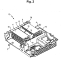
- Fig. 2 shows a section of a base assembly 12 of a drying unit 1 in a view from above at an angle, with the first heat exchanger 4 and the second heat exchanger 6 arranged at a distance behind it in the direction of flow of the process air P.
- a flow guide structure 13 is now additionally arranged between the two heat exchangers.
- the associated sectional plane lies in the horizontal in such a way that a top cover of the flow guide structure 13 is cut off and therefore not shown.
- the flow guide structure 13 is thus shown open at the top.
- the first heat exchanger 4 has a cuboid basic shape. Moist process air P enters at its air inlet surface 4a, where it is cooled and condensed out. The process air P then flows through the flow guide structure 13 and through the second heat exchanger 6, where it is heated.
- the second heat exchanger 6 also has a cuboid basic shape. The first heat exchanger 4, the second heat exchanger 6 and the flow guide structure 13 form the air guide channel there and have the same flow width.
- the process air P can be introduced into the laundry drum 2.
- the water entrained and used for cleaning the second heat exchanger 6 may, for example, drip or rain off the second heat exchanger 6, for example into a water tank.
- the base assembly 12 has a common base-side support 28 and can be pre-fitted with the first heat exchanger 4, the second heat exchanger 6 and the flow guide structure 13 and then installed as a base-side module in the heat pump laundry dryer 1.
- the flow guide structure 13 can be used as a prefabricated component between the first heat exchanger and the second heat exchanger, in particular it can be plugged in.
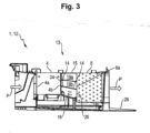
- Fig. 3 shows a cross-section of the base assembly of Fig. 2 longitudinally through the heat exchangers 4, 6 and the flow guide structure 13.
- the sectional plane here corresponds to a vertical plane.
- the first heat exchanger 4, the second heat exchanger 6 and the flow guiding structure 13 extend at least approximately to the same height, with their tops lying at least approximately flush with each other. Moreover, since the first heat exchanger 4 has a lower height than the second heat exchanger 6, a lower surface of the first heat exchanger 4 is higher than a lower surface of the second heat exchanger 6. As a result, an air outlet surface 4b of the first heat exchanger 4 also has a higher lower surface or a higher lower edge than an air inlet surface 6a of the second heat exchanger 6.
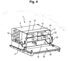
- Fig. 4 shows an oblique top view of a portion of the bottom assembly 12 including the first heat exchanger 4 and the flow guiding structure 13, while the second heat exchanger 6 is not shown. This provides an air outlet side view of the flow guide structure 13.
- the flow guide structure 13 used in one embodiment of the process according to the invention shows two band- or strip-shaped flat flow guide elements 14 aligned at least approximately horizontally between the first heat exchanger 4 and the second heat exchanger 6.
- the flow guide elements 14 thus run transversely to the process air duct with respect to their longitudinal extent or are installed transversely in the process air duct.
- the flow guide elements 14 are arranged one above the other, and here they are inclined downwardly by between 5° and 10° with respect to the horizontal in the direction of flow, but are not inclined in the transverse direction. Consequently, an edge of the flow guide elements 14 facing the first heat exchanger 4 is higher than a respective edge facing the second heat exchanger 6.
- the ceiling 15 and the floor 16 are also largely band- or strip-shaped.
- the floor 16 may also be considered a flow directing element.
- the ceiling 15 and/or the floor 16 may have been manufactured together with the flow directing elements 14 and side walls 17 as one component, but may alternatively be separate components to the flow directing elements 14 and the side walls 17.
- the two flow directing elements 14, the ceiling and the floor 16 are laterally bounded by common, vertically oriented side walls 17.
- a vertically aligned partition 18 is also inserted centrally at the two flow guide elements 14 and the ceiling 15.
- the flow guide structure 13 has five laterally circumferentially closed air guide channels 19a, 19b, 20a, 20b and 21.
- the two air guide channels 19a and 20a arranged side by side are formed by the upper flow guide element 14, the ceiling 15, the partition wall 18 and a respective side wall 17.
- the two side-by-side air guide channels 19b and 20b are formed by the two flow guide elements 14, the partition 18 and a respective side wall 17.
- the air guide channel 21 is formed by the bottom 16, the lower air guide element 14 and the two side walls 17 and is twice as wide as the air guide channels 19a, 19b, 20a and 20b.
- the air ducts 19a, 19b and 21 as well as the air ducts 20a, 20b and 21 are arranged one above the other.
- the air ducts 19a, 19b and 21 and 20a, 20b and 21 are separated from each other by the upper flow directing element 14 and the lower flow directing element 14, respectively. At least the air ducts 19a, 19b, 20a and 20b are arranged in a grid shape relative to each other.
- a first open side 24 of the flow guiding structure 13 facing the first heat exchanger 4 (which comprises corresponding first open sides of the air guiding channels 19a, 19b, 20a, 20b, 21) may be directly adjacent to an air outlet surface 4b of the first heat exchanger 4, touching it and/or having a small distance (of advantageously not more than 10 mm).
- the first open side 24 of the flow guiding structure 13 may cover the entire air outlet surface 4b or only a part thereof.
- a second open side 26 of the flow guiding structure 13 facing the second heat exchanger 6 (which comprises corresponding second open sides of the air guiding channels 19a, 19b, 20a, 20b, 21) may be directly adjacent to the air inlet surface 6a of the second heat exchanger 6, touching it and/or having a small distance (of advantageously not more than 10 mm).
- the second open side 26 of the flow guiding structure 13 may completely or only partially cover the air inlet surface 6b.
- the provision of the flow guide structure 13 results in the advantage that a sinking of the water W entrained with the process air P between the two heat exchangers 4, 6 can be reduced or even partially prevented by the flow guide elements 14 and optionally 16, whereby the second heat exchanger 6 can be cleaned at a higher level by means of the entrained water W than without the flow guide structure 13.
- the flow guiding elements 14 and possibly 16 can cause water droplets approaching or falling from above to experience a higher counterforce in the region of the flow guiding elements 14 and possibly 16 due to a dynamic pressure or the like than in free fall, so that a range of the water droplets in the horizontal direction or flow direction is increased.
- the effect occurs that the water droplets can settle on the flow guide elements 14 and possibly 16 and create a water film there, which is pressed by the flowing process air P in the direction of the second heat exchanger 6.
- the water W can detach or break off and be carried along by the process air P to the second heat exchanger 6.
- an impact height of the water W on the second heat exchanger 6 can also be improved and also comparatively precisely adjusted by adjusting a position of the flow guide elements 14 and optionally 16.
- Retaining lugs 22 and plug-in elements 23 for fixing the flow guide structure 13 are provided on the outside of the side walls 17 of the flow guide structure 13.
- the flow guide structure 13 can be inserted in particular from above into the space between the two heat exchangers 4 and 6 and e.g. by means of the plug-in elements 23.
- the flow guide structure 13 or the two flow guide elements 14, top 15, the bottom 16 and the two side walls 17 may have been manufactured as one part, e.g. as an injection-molded part made of plastic. However, they may also have been assembled in several parts, e.g. by means of several sheet metal parts. Cleaning of the second heat exchanger 6 can be carried out during or outside a drying process.
Landscapes
- Engineering & Computer Science (AREA)
- Textile Engineering (AREA)
- Detail Structures Of Washing Machines And Dryers (AREA)
Abstract
the method comprising the following steps in a drying phase in which the drum (2) is at least temporarily rotated and the blower (7) is switched on:
(a) determining whether a predetermined minimum amount Mmin of the aqueous cleaning liquid (W) is present in the cleaning device (5);
(b1) when the minimum quantity Mmin of aqueous cleaning liquid (W) is present in the cleaning device (5), switching off the compressor (8);
(b2) when the minimum quantity Mmin of aqueous cleaning liquid (W) is not present in the cleaning device (5), the following steps (c), (c1), (c2) and (d) are skipped;
(c) activating the cleaning device (5) so that aqueous cleaning liquid (W) is conveyed into the first heat exchanger (4), wherein during the conveyance of the aqueous cleaning liquid
(c1) in the event that a moisture content H of the laundry items is above a predetermined moisture content HAT, the blower (7) is operated at a power P1 sufficient to convey at least part of the aqueous cleaning liquid (W) from the first heat exchanger (4) into the second heat exchanger (6); and
(c2) in the event that a moisture content H of the laundry items is below a predetermined moisture content HCD, where HAT > HCD, operating the blower (7) at a power P2 < P1 insufficient to convey at least a portion of the aqueous cleaning liquid (W) from the first heat exchanger (4) to the second heat exchanger (6), and interrupting rotation of the drum (2);
(d) pumping condensate, preferably from a condensate pan in a bottom group (12), by means of a pump into the cleaning device (5) until at least the minimum quantity Mmin of aqueous cleaning liquid (W) is again present in the cleaning device (5), wherein in case (c2) the rotation of the drum (2) is resumed before the pumping after de-activation of the cleaning device (5);
(e) repeating steps (c) and (d) at least once; and then
(f) in case (c1), restarting the compressor (8); and
(g) in case (c2), rinsing the first heat exchanger (4) when the temperature inside the drum (2) reaches a pre-defined limit Tlim.
Description
- The invention relates to a method of operating a drying apparatus with a heat pump and a cleaning device. The invention relates more particularly to a method of operating a drying apparatus comprising a drum for receiving laundry items; a heat pump having an evaporator as a first heat exchanger, a condenser as a second heat exchanger, which are arranged in a process air duct at a distance one behind the other with respect to the flow direction thereof, a compressor and an expansion valve; a blower arranged in the process air duct, and a cleaning device for cleaning the first heat exchanger with an aqueous cleaning liquid (W).
- Condensation laundry dryers are known that have a drum rotatably mounted in a housing, a fan for generating a process air stream intended to flow through the drum as well as over a condensation device comprising a collecting vessel for collecting condensed water accumulating during the drying process, and in addition a condensate tank connected to the collecting vessel by means of a line, the condensate tank being arranged in a trough connected to the collecting vessel by means of a drain. In this case, the condensate collected in the collecting vessel is usually conveyed to the condensate tank by means of a pump. The condensate tank is located in a trough which contains a drain to the collecting vessel.
- Household appliances with a heat exchanger cleaning device are known.
- The publication
WO 2017/032550 A1 describes a domestic appliance having a first heat exchanger and a second heat exchanger, which are arranged one behind the other at a distance from each other in a process air duct with respect to the flow direction of said process air duct, and a cleaning apparatus for cleaning the first heat exchanger by means of cleaning liquid (W), wherein a flow-guiding structure is present in the process air duct between the first heat exchanger and the second heat exchanger, which flow-guiding structure has at least one planar flow-guiding element, which is oriented at least approximately horizontally between the first heat exchanger and the second heat exchanger, wherein the at least one flow-guiding element is arranged above a bottom of the flow-guiding structure. The domestic appliance is in particular a clothes-drying appliance having a heat pump. - Condensation laundry dryers are known that have a drum rotatably mounted in a housing, a fan for generating a process air stream intended to flow through the drum as well as over a condensation device comprising a collecting vessel for collecting condensed water accumulating during the drying process, and in addition a condensate tank connected to the collecting vessel by means of a line, the condensate tank being arranged in a trough connected to the collecting vessel by means of a drain. In this case, the condensate collected in the collecting vessel is usually conveyed to the condensate tank by means of a pump. The condensate tank is located in a trough which contains a drain to the collecting vessel.
- In view of this situation it was an object of the present invention to provide an improved process for operating a drying apparatus with a heat pump. Preferably, the overall efficiency of the operation of the dryer should be improved in that an improved method for cleaning a heat exchanger of the heat pump is provided, in particular for cleaning a heat exchanger arranged in a process air circuit at a distance behind a directly cleanable heat exchanger.
- This object is achieved according to the present invention by the method of operating a drying apparatus with a heat pump and a heat exchanger cleaning device pursuant to the independent claim. Preferred embodiments of the method according to the invention are shown especially in the dependent claims.
- The invention is thus directed to a method of operating a drying apparatus comprising a drum for receiving laundry items; a heat pump having an evaporator as a first heat exchanger and a condenser as a second heat exchanger, which are arranged in a process air duct at a distance one behind the other with respect to the flow direction thereof, a compressor and an expansion valve; a blower arranged in the process air duct, and a cleaning device for cleaning the first heat exchanger with an aqueous cleaning liquid (W), the method comprising the following steps in a drying phase in which the drum is at least temporarily rotated and the blower is switched on:
- (a) determining whether a predetermined minimum amount Mmin of the aqueous cleaning liquid (W) is present in the cleaning device;
- (b1) when the minimum quantity Mmin of aqueous cleaning liquid (W) is present in the cleaning device, switching off the compressor;
- (b2) when the minimum quantity Mmin of aqueous cleaning liquid (W) is not present in the cleaning device, the following steps (c), (c1), (c2) and (d) are skipped;
- (c) activating the cleaning device so that aqueous cleaning liquid (W) is conveyed into the first heat exchanger, wherein during the conveyance of the aqueous cleaning liquid
- (c1) in the event that a moisture content H of the laundry items is above a predetermined moisture content HAT, the blower is operated at a power P1 sufficient to convey at least part of the aqueous cleaning liquid (W) from the first heat exchanger into the second heat exchanger; and
- (c2) in the event that a moisture content H of the laundry items is below a predetermined moisture content HCD, where HAT > HCD, operating the blower at a power P2 < P1 insufficient to convey at least a portion of the aqueous cleaning liquid (W) from the first heat exchanger to the second heat exchanger, and interrupting rotation of the drum;
- (d) pumping condensate, preferably from a condensate pan in a bottom group, by means of a pump into the cleaning device until at least the minimum quantity Mmin of aqueous cleaning liquid (W) is again present in the cleaning device, wherein in case (c2) the rotation of the drum is resumed before the pumping after de-activation of the cleaning device;
- (e) repeating steps (c) and (d) at least once; and then
- (f) in case (c1), restarting the compressor; and
- (g) in case (c2), rinsing the first heat exchanger when the temperature inside the drum reaches a pre-defined limit Tlim.
- In a preferred method, steps (c1) and (d) are repeated a pre-defined number of times nset1, preferably twice, and more preferably three times.
- In a preferred method, step (b2) can be repeated a pre-defined number nset2 of times. In case this pre-defined number nset is reached, the drying apparatus will indicate, in particular display, a separate cleaning request to the user of the drying apparatus.
- In a preferred method according to the present invention, steps (a), (b1), (b2), and (c1) can be executed if and only if a pre-defined operation time tset is reached.
- In a particularly preferred method of the present invention, a flow guide structure is present in the drying apparatus in the process air duct between the first heat exchanger and the second heat exchanger, which flow guide structure has at least one flat flow guide element which is aligned at least approximately horizontally between the first heat exchanger and the second heat exchanger, and is arranged above a bottom of the process air duct.
- It is preferred in this method, that at least one flow guiding element is strip-shaped and extends transversely to the process air duct with respect to its longitudinal extension.
- Preferably, for the method of the present invention, the first heat exchanger, the second heat exchanger and the flow guide structure have an equal flow width.
- In a particularly preferred method of the present invention
- the flow guide structure is a grid-like flow guide structure which has at least two circumferentially closed air guide channels arranged one above the other,
- which air guide channels arranged one above the other are separated from one another by a common flow guide element,
- first open end faces of the air guide channels face an air outlet side of the first heat exchanger, and
- second open end faces of the air guide channels face an air inlet side of the second heat exchanger.
- A method is then preferred, wherein the flow guide structure has at least two arrangements, arranged next to one another, of in each case at least two circumferentially closed air guide channels arranged one above the other.
- In a preferred embodiment of the process of the present invention, in the drying apparatus the first heat exchanger and the second heat exchanger are arranged on a common base and the flow guiding structure can be inserted as a prefabricated component between the first heat exchanger and the second heat exchanger.
- In the method of the present invention it is preferred that the measurement of the moisture content H of the laundry items is performed by means of a conductivity sensor arranged in the drum.
- In the method of the present invention it is moreover preferred that the determination of the amount of water M in the cleaning device is carried out by means of a water level sensor and/or a counter for pumping operations of the pump.
- The drying apparatus comprises a heat pump. The drying apparatus thus contains in general a heat pump circuit comprising a refrigerant channel for circulating a refrigerant, a condenser as a heat source, an evaporator as a heat sink, an expansion device for expanding the refrigerant, and a compressor for driving and compressing the refrigerant, the refrigerant circulating sequentially through the compressor, the condenser, the expansion device and the evaporator. The condenser serves to heat the process air flow prior to entering the drum as drying chamber, and the evaporator serves to cool the air flow after leaving the drying chamber.
- In an embodiment in which the drying device used has a flow-guiding element, the process has the advantage that the flow-guiding element can reduce or even partially prevent a sinking of the entrained water between the two heat exchangers, whereby the second heat exchanger can be cleaned at a higher level by means of the entrained water than without the flow-guiding structure. Namely, the flow directing element can cause water droplets approaching or falling from above to experience a higher counterforce in the region of the flow directing element due to a dynamic pressure than in free fall, so that a range of the water droplets in the horizontal direction is increased. In addition, the water droplets settle on the flow guide element and can generate a water film there, which is pressed by the flowing process air in the direction of the second heat exchanger. At the free edge of the flow guide element facing the second heat exchanger, the water can detach from the flow guide element and be carried along by the process air back to the second heat exchanger. Thus, an impact height on the second heat exchanger can also be improved and also adjusted by adjusting a position of the flow directing elements. The cleaning device may include, for example, a nozzle or downcomer pressurizable with the cleaning fluid. The cleaning fluid is generally an aqueous fluid, for example water. In particular, the cleaning fluid may comprise or be fresh water and/or condensate. The water may have additives such as cleaning agents.
- An at least approximately horizontally oriented flow directing element may in particular be a planar element oriented horizontally or substantially horizontally in the direction from the evaporator to the condenser. A substantially horizontal orientation can be understood as an orientation which deviates from the horizontal by no more than 45°, i.e. by no more than +45° or -45°). In particular, the direction may be measured between the end points of the flow directing element.
- The optional at least one flow directing element is preferably arranged above a bottom of the air flow channel, which in particular comprises that it is arranged at a distance from said bottom. Consequently, there is a flow cross-section for the process air between the bottom of the air flow channel and the flow guide element (in the case of a plurality of flow guide elements arranged spaced apart one above the other, between this bottom and the lowest flow guide element adjacent thereto).
- The flow guide structure may be a separately manufactured component insertable as a section of the air flow channel or as an insert into the air flow channel.
- The bottom of the flow directing structure may match the bottom of the air flow channel in that section. Alternatively, the bottom of the flow directing structure may be spaced from the bottom of the air flow channel. Similarly, a ceiling of the flow directing structure may coincide with a ceiling of the air directing channel in that section. Alternatively, the ceiling of the flow directing structure may be spaced from the ceiling of the air directing channel, in particular below or below.
- In a preferred embodiment, which is advantageous in terms of effective, low-loss flow conduction, the flow conducting element has a smooth, in particular planar or simply curved, surface. Flow resistance and water deposits on the flow guide element can then be effectively avoided.
- The flow guide element can be made of metal or plastic, for example. The metal can be a stainless metal and/or have a corrosion-preventing coating. The flow directing element may be assembled from a plurality of individual parts, e.g., pieces of sheet metal, or may be a single piece, e.g., as an injection molded plastic part.
- The drying apparatus used in the method according to the invention may be a stand-alone clothes dryer or a washer-dryer. The process air duct may be a closed process air duct ("recirculating air dryer") or an open process air duct ("exhaust air dryer").
- It is a further embodiment of the process of the present invention that at least one flow guide element is designed in the form of a band or strip and, with respect to its longitudinal extent, runs in particular transversely to the process air duct. This enables a particularly easy-to-implement possibility of influencing the air flow and movement of the water over a large - in particular full - width of the air flow channel. In particular, a flow directing element can be formed as a straight, planar strip of material.
- In accordance with the present invention, it is preferred that at least one flow guide element extends over substantially the entire width of the process air duct in the drying apparatus used. Here, "substantially the entire width" is understood to mean in particular the entire width or at least 90% of the entire width. This effectively suppresses parasitic air flows that could flow laterally past the flow directing element, thereby reducing effectiveness of cleaning the second heat exchanger.
- In a further embodiment, the first heat exchanger, the second heat exchanger and the preferably used flow directing structure in the drying apparatus have an equal flow width. In this way, a particularly uniform flow can be achieved. A flow width can be understood in particular as a width of the respective associated air flow channel.
- According to the invention, it is furthermore preferred that in one embodiment at least two flow guide elements are arranged one above the other. In this way, a height of fall of the water in the gap between the two heat exchangers can be limited particularly effectively, namely by the height of the flow guide elements, in particular by a height of the edge facing the second heat exchanger. More preferably, the bottom of the flow guiding structure and/or the bottom of the air flow channel represents or is another flow guiding element.
- Alternatively, the bottom does not constitute a flow directing element for distributing the water impinging on the second heat exchanger.
- It is further preferred that an air outlet side of the first heat exchanger has a higher bottom than an air inlet side of the second heat exchanger, and an edge of at least one flow directing element facing the first heat exchanger is higher than its edge facing the second heat exchanger.
- The potential flow guiding element thus runs obliquely downward in the direction of flow of the process air P against a horizontal line. As a result, a height of the water impinging on the second heat exchanger can also be raised independently of the flow guide structure. The flow guide structure can be designed more simply and effectively in this way.
- The first heat exchanger may be at the same height as the second heat exchanger, higher than the second heat exchanger, or lower than the second heat exchanger. In a preferred embodiment of the process, the first heat exchanger has a lower height than the second heat exchanger. This makes it possible to achieve an at least approximately equal installation height of the two heat exchangers.
- In the process according to the invention, it is moreover preferred that the upper sides of the first heat exchanger used and of the second heat exchanger used are aligned flush with one another and, in particular, occupy the same height plane.
- Finally, in a preferred embodiment of the process, a flow guide structure is used which has a bottom and a top and at least one flow guide element is arranged between the bottom and the top, in particular in a laterally horizontal orientation. This results in a particularly compact and fluidically effective arrangement. For a particularly effective distribution of the water impinging on the second heat exchanger, a plurality of flow guide elements can be arranged between the floor and the ceiling. The several flow guiding elements can have an equal or different distance to each other and/or to the floor and/or to the ceiling. The floor and/or ceiling can be designed as further flow guide elements, but can alternatively be structural elements without a flow guide function for distributing the water impinging on the second heat exchanger (but possibly for the process air).
- If a flow-guiding structure is used, this is preferably a grid-like flow-guiding structure which has at least two circumferentially closed air-guiding channels arranged one above the other, the air-guiding channels arranged one above the other being separated from one another by a flow-guiding element. This results in a particularly compact arrangement. In this preferred embodiment, at least one flow guide element thus represents in particular the bottom of an upper air guide channel as well as the top of a lower air guide channel. The flow guide elements can be spaced from the bottom of the air flow channel or arranged above this bottom.
- It is also advantageous that a first open end face of at least one air guide channel faces an air outlet side of the first heat exchanger and a second open end face of the at least one air guide channel faces an air inlet side of the second heat exchanger. This results in the advantage that a particularly straight air guide channel can be achieved between the two heat exchangers.
- According to the process of the present invention, it is particularly advantageous if the optionally but preferably used flow guide structure - in particular its first open end face - is directly adjacent to or spaced from the air outlet side of the first heat exchanger, in particular at a distance of no more than ten millimeters, in particular no more than five millimeters. Such a distance facilitates easy insertion of the flow guide structure while effectively reducing a drop in height of the water droplets.
- It is advantageous if the optionally used flow guide structure - in particular its second open end face - is directly adjacent to or spaced from the air inlet side of the second heat exchanger, in particular at a distance of no more than ten millimeters, preferably no more than five millimeters. Such a distance also facilitates easy insertion of the flow guiding structure while effectively reducing a drop in height of the water droplets. The flow directing structure or at least one flow directing element may contact at least one heat exchanger.
- In a further embodiment, the flow guide structure has at least two arrangements arranged next to each other, each comprising at least two circumferentially closed air guide channels arranged one above the other. In this way, cross-flows, which increase a waterfall due to a path extension for the water droplets, can be suppressed. The resulting stronger channeling of the air flows can also increase an air velocity, which suppresses a waterfall even more.
- In a further embodiment, air ducts arranged next to each other are separated from each other by a common - in particular vertical - partition wall. This enables a particularly compact design.
- It is another embodiment that the air ducts have a rectangular cross-section when viewed in the direction of flow. This results in the advantage that the flow structure can be implemented by a rectangular arrangement of flat planar components or partial areas, which enables particularly simple and inexpensive manufacture. This applies in particular to a multi-part design of the flow structure.
- It is a further embodiment that the flow guide structure or the air guide channels have a grid-like basic shape with the air guide channels as the grid openings. It is another embodiment that the first heat exchanger and the second heat exchanger are arranged on a common support - in particular a base - and the flow guide structure can be inserted as a prefabricated component between the first heat exchanger and the second heat exchanger. This enables a particularly simple assembly.
- The floor can be a floor of the drying apparatus. For a particularly simple assembly of the drying apparatus, the floor may be a floor of a floor assembly serving as a module of the drying apparatus. The floor assembly can, for example, be prefabricated and then inserted as a module into the drying apparatus and connected there.
- Thus, the invention provides also a bottom assembly of a drying apparatus on which the first heat exchanger, the second heat exchanger and, in between, the flow guiding structure are arranged.
- The drying apparatus can be a dryer as such or a washer-dryer which combines the function of washing laundry with the function of drying.
- In the present invention, a condensate collecting vessel is for the condensation water produced during the drying process, which is pumped to the cleaning device in general by means of an electric pump unit via a pump conduit which is usually a hose. The condensate collecting vessel is for example a tray open at the top and arranged below the condensing device, here the evaporator of the heat pump, so that it can collect condensate produced in the evaporator.
- The water in the condensate collecting vessel is conveyed to the cleaning device which is preferably arranged on an upper portion of the drying apparatus.
- The drying apparatus is a front-loading dryer, which means that a drum in which the laundry is located has an axis which is positioned in a horizontal manner or slightly tilted with respect to the horizontal plane, or a top dryer, where the axis of the drum is substantially vertical. In a preferred embodiment, the drying apparatus is a front loading laundry dryer.
- The process air circuit, in particular a closed-loop circuit, includes a process air conduit for channeling a stream of air to dry the laundry load in the drum. The process air circuit is connected with its two opposite ends to the drum. More specifically, hot dry air is fed into the drying chamber, flowing over the laundry, and the resulting humid (and to a lower temperature cooled down) air exits the same. In case of a closed-loop drying air circuit, the humid process air is then fed into the evaporator of the heat pump, where the moist process air is further cooled down and the humidity present therein condenses. The resulting cool dry air is then heated up before re-entering again in the drum by means of the condenser of the heat pump, and the whole loop is repeated until the end of the drying process. However, the dehumidified process air can also be exhausted outside the dryer.
- The drying apparatus in general comprises a control unit for the operation of the drying apparatus.
- The invention provides several advantages. Advantages of the invention include an improvement of the performance of the dryer by providing a drying apparatus with an improved maximum drying performance of the drying apparatus that can be achieved over lifetime due to an efficient removal of laundry residuals. Moreover, in embodiments of the invention, a maximum drying performance of the drying apparatus over lifetime can be achieved due to filtering the laundry residuals from the air entering the condenser of the heat pump. A stable dryer performance over lifetime of the dryer is possible.
- Non-limiting examples for drying apparatuses or for parts in which the method of the present invention can be advantageously implemented are shown in Figs. 1 to
4 , wherein corresponding components are identified by the same reference numerals. - Fig. 1 shows a schematic structure of a drying unit in which no flow guide structure is present;
-
Fig. 2 shows a section of a floor assembly with a first heat exchanger, a second heat exchanger and a flow guide structure arranged therebetween in an oblique view from above; -
Fig. 3 shows a cross-section of the floor assembly ofFig. 2 longitudinally through the heat exchangers and the flow directing structure; and -
Fig. 4 shows an oblique front view of a portion of the floor assembly including the first heat exchanger and the flow directing structure. - Fig. 1 shows a schematic structure of a
drying apparatus 1 of corresponding genus. In this embodiment, the latter has a horizontallyrotatable laundry drum 2 as a receiving space for laundry to be dried, which is not shown here. During a drying process, dry-warm process air P penetrates from aprocess air duct 3 serving as an air flow duct into thelaundry drum 2 and sweeps over the laundry present there. In the process, the process air P absorbs moisture. The now moist, warm process air P exits thelaundry drum 2 again and is guided through theprocess air duct 3 to a first heat exchanger 4. The first heat exchanger 4 cools the process air P, which thereby condenses out. A heat exchanger surface of the first heat exchanger 4 located in theprocess air duct 3 is thereby covered by a moisture film from which condensation water droplets detach and fall down, e.g. into a collecting tray not shown here. However, the moisture film also holds particles such as lint and hair present in the process air P on the heat exchanger surface, which remain stuck there even after the moisture film has evaporated and can reduce an effectiveness of the first heat exchanger 4. In order to remove the lint, hair, etc. from the first heat exchanger 4, acleaning device 5 may be used which cleans the heat exchanger surface of the first heat exchanger 4 using water W under a high momentum as a cleaning agent. Thecleaning device 5 may, for example, comprise a nozzle in communication with a pump and directed towards the first heat exchanger 4. Thecleaning device 5 may alternatively comprise a downpipe in communication with a water reservoir to be selectively opened, which is not shown here, so that water W discharged at high velocity in the downpipe impinges on the first heat exchanger 4 from above. The downpipe may be formed with a nozzle system on the outlet side to produce a more widely spread water curtain. From the first heat exchanger 4, the now drier process air P is led to asecond heat exchanger 6, which heats the process air P again. The first heat exchanger 4 and thesecond heat exchanger 6 are thus arranged at a distance from each other in relation to the direction of flow of the process air P. The first heat exchanger 4 is located at the end of thesecond heat exchanger 6. - From the
second heat exchanger 6, the process air P, which is now dry and warm again, is introduced into thewashing drum 2 through theprocess air duct 3. Theprocess air duct 3 thus forms a closed process air circuit with thelaundry drum 2. A fan orventilator 7 may be provided for circulating the process air P in the process air circuit. From the point of view of the process air P, the first heat exchanger 4 acts as a condenser and thesecond heat exchanger 6 acts as a heater. - The first heat exchanger 4 and the
second heat exchanger 6 are designed here as parts of a heat pump, which also has a drive in the form of acompressor 8 and an expansion valve 9. In the arrangement shown, thesecomponents refrigerant tubes 10 in which working fluid or refrigerant K circulates. The operation of a heat pump is basically well known and need not be further explained here. From the point of view of the heat pump, the first heat exchanger 4 serves as an evaporator and thesecond heat exchanger 6 as a condenser. - Lint and hair are deposited mainly on the moist first heat exchanger 4, but also to a small extent on the
second heat exchanger 6. In order to be able to clean thesecond heat exchanger 6 as well, thecleaning device 5 is operated with thefan 7 running. As a result, water W (e.g. in the form of a water curtain), which is present in the process air P in the area of the first heat exchanger 4, is partially entrained with the process air P and reaches thesecond heat exchanger 6, which is cleaned in the area of the impinging water W. Thesecond heat exchanger 6 is cleaned in the area of the impinging water W. - In principle, the
second heat exchanger 6 can be cleaned in a process independent of a process for cleaning the first heat exchanger 4. For example, thefan 7 can be operated to clean thesecond heat exchanger 6 and not operated to clean the first heat exchanger. Cleaning of thesecond heat exchanger 6 may be performed during a drying process or in a separate cleaning process. For example, approximately 50% of the water W directed to the first heat exchanger 4 may be diverted or transferred to thesecond heat exchanger 6 during operation of thefan 7. A position of thefan 7 in theprocess air duct 3 is in principle not limited. For example, in addition to being arranged between thelaundry drum 2 and the first heat exchanger 4, thefan 7 may also be arranged between thesecond heat exchanger 6 and thelaundry drum 2. - If different sizes of the first heat exchanger 4 and the
second heat exchanger 6 are used - for example, for technical and economic reasons - a given installation space may result in significantly different distances between them. This can be disadvantageous because a trajectory of the entrained water droplets (indicated by the dashed arrow) in the area between the first heat exchanger 4 and thesecond heat exchanger 6 is increasingly influenced by their own weight, or the trajectory there is particularly dependent on their own weight. At a large distance, the water W therefore disadvantageously reaches only low areas of thesecond heat exchanger 6, as shown in simplified form in Fig. 1. -
Fig. 2 shows a section of abase assembly 12 of adrying unit 1 in a view from above at an angle, with the first heat exchanger 4 and thesecond heat exchanger 6 arranged at a distance behind it in the direction of flow of the process air P. Aflow guide structure 13 is now additionally arranged between the two heat exchangers. The associated sectional plane lies in the horizontal in such a way that a top cover of theflow guide structure 13 is cut off and therefore not shown. Theflow guide structure 13 is thus shown open at the top. - The first heat exchanger 4 has a cuboid basic shape. Moist process air P enters at its
air inlet surface 4a, where it is cooled and condensed out. The process air P then flows through theflow guide structure 13 and through thesecond heat exchanger 6, where it is heated. Thesecond heat exchanger 6 also has a cuboid basic shape. The first heat exchanger 4, thesecond heat exchanger 6 and theflow guide structure 13 form the air guide channel there and have the same flow width. - After leaving the
second heat exchanger 6, the process air P can be introduced into thelaundry drum 2. The water entrained and used for cleaning thesecond heat exchanger 6 may, for example, drip or rain off thesecond heat exchanger 6, for example into a water tank. - The
base assembly 12 has a common base-side support 28 and can be pre-fitted with the first heat exchanger 4, thesecond heat exchanger 6 and theflow guide structure 13 and then installed as a base-side module in the heatpump laundry dryer 1. In particular, theflow guide structure 13 can be used as a prefabricated component between the first heat exchanger and the second heat exchanger, in particular it can be plugged in. -
Fig. 3 shows a cross-section of the base assembly ofFig. 2 longitudinally through theheat exchangers 4, 6 and theflow guide structure 13. The sectional plane here corresponds to a vertical plane. - The first heat exchanger 4, the
second heat exchanger 6 and theflow guiding structure 13 extend at least approximately to the same height, with their tops lying at least approximately flush with each other. Moreover, since the first heat exchanger 4 has a lower height than thesecond heat exchanger 6, a lower surface of the first heat exchanger 4 is higher than a lower surface of thesecond heat exchanger 6. As a result, anair outlet surface 4b of the first heat exchanger 4 also has a higher lower surface or a higher lower edge than an air inlet surface 6a of thesecond heat exchanger 6. -
Fig. 4 shows an oblique top view of a portion of thebottom assembly 12 including the first heat exchanger 4 and theflow guiding structure 13, while thesecond heat exchanger 6 is not shown. This provides an air outlet side view of theflow guide structure 13. - With reference to
Fig. 3 andFig. 4 , theflow guide structure 13 used in one embodiment of the process according to the invention shows two band- or strip-shaped flatflow guide elements 14 aligned at least approximately horizontally between the first heat exchanger 4 and thesecond heat exchanger 6. The flow guideelements 14 thus run transversely to the process air duct with respect to their longitudinal extent or are installed transversely in the process air duct. The flow guideelements 14 are arranged one above the other, and here they are inclined downwardly by between 5° and 10° with respect to the horizontal in the direction of flow, but are not inclined in the transverse direction. Consequently, an edge of theflow guide elements 14 facing the first heat exchanger 4 is higher than a respective edge facing thesecond heat exchanger 6. Above the twoflow guide elements 14 there is a horizontally alignedceiling 15 and below this afloor 16 which slopes downwards or downwardly in the direction of flow towards the horizontal. Theceiling 15 and thefloor 16 are also largely band- or strip-shaped. Thefloor 16 may also be considered a flow directing element. Theceiling 15 and/or thefloor 16 may have been manufactured together with theflow directing elements 14 andside walls 17 as one component, but may alternatively be separate components to theflow directing elements 14 and theside walls 17. - As shown in
Fig. 4 , the twoflow directing elements 14, the ceiling and thefloor 16 are laterally bounded by common, vertically orientedside walls 17. A vertically alignedpartition 18 is also inserted centrally at the twoflow guide elements 14 and theceiling 15. As a result of this design, theflow guide structure 13 has five laterally circumferentially closedair guide channels air guide channels flow guide element 14, theceiling 15, thepartition wall 18 and arespective side wall 17. The two side-by-sideair guide channels flow guide elements 14, thepartition 18 and arespective side wall 17. Theair guide channel 21 is formed by the bottom 16, the lowerair guide element 14 and the twoside walls 17 and is twice as wide as theair guide channels air ducts air ducts air ducts flow directing element 14 and the lowerflow directing element 14, respectively. At least theair ducts - A first
open side 24 of theflow guiding structure 13 facing the first heat exchanger 4 (which comprises corresponding first open sides of theair guiding channels air outlet surface 4b of the first heat exchanger 4, touching it and/or having a small distance (of advantageously not more than 10 mm). The firstopen side 24 of theflow guiding structure 13 may cover the entireair outlet surface 4b or only a part thereof. A secondopen side 26 of theflow guiding structure 13 facing the second heat exchanger 6 (which comprises corresponding second open sides of theair guiding channels second heat exchanger 6, touching it and/or having a small distance (of advantageously not more than 10 mm). The secondopen side 26 of theflow guiding structure 13 may completely or only partially cover the air inlet surface 6b. The provision of theflow guide structure 13 results in the advantage that a sinking of the water W entrained with the process air P between the twoheat exchangers 4, 6 can be reduced or even partially prevented by theflow guide elements 14 and optionally 16, whereby thesecond heat exchanger 6 can be cleaned at a higher level by means of the entrained water W than without theflow guide structure 13. Namely, theflow guiding elements 14 and possibly 16 can cause water droplets approaching or falling from above to experience a higher counterforce in the region of theflow guiding elements 14 and possibly 16 due to a dynamic pressure or the like than in free fall, so that a range of the water droplets in the horizontal direction or flow direction is increased. Also, the effect occurs that the water droplets can settle on theflow guide elements 14 and possibly 16 and create a water film there, which is pressed by the flowing process air P in the direction of thesecond heat exchanger 6. At the free edge of theflow guide elements 14 and possibly 16 facing thesecond heat exchanger 6, the water W can detach or break off and be carried along by the process air P to thesecond heat exchanger 6. Thus, an impact height of the water W on thesecond heat exchanger 6 can also be improved and also comparatively precisely adjusted by adjusting a position of theflow guide elements 14 and optionally 16. Retaining lugs 22 and plug-inelements 23 for fixing theflow guide structure 13 are provided on the outside of theside walls 17 of theflow guide structure 13. - The
flow guide structure 13 can be inserted in particular from above into the space between the twoheat exchangers 4 and 6 and e.g. by means of the plug-inelements 23. Theflow guide structure 13 or the twoflow guide elements 14, top 15, the bottom 16 and the twoside walls 17 may have been manufactured as one part, e.g. as an injection-molded part made of plastic. However, they may also have been assembled in several parts, e.g. by means of several sheet metal parts. Cleaning of thesecond heat exchanger 6 can be carried out during or outside a drying process. -
- 1
- Heat pump clothes dryer; drying apparatus
- 2
- Drum; laundry drum
- 3
- Process air duct
- 4
- First heat exchanger; evaporator of heat pump
- 4a
- Air inlet area of the first heat exchanger
- 4b
- Air outlet area of the first heat exchanger
- 5
- Cleaning device
- 6
- Second heat exchanger; condenser of heat pump
- 6a
- Air inlet area of the second heat exchanger
- 7
- Fan
- 8
- Compressor
- 9
- Expansion valve
- 10
- Refrigerant pipe
- 12
- Base assembly
- 13
- Flow guide structure
- 14
- Flow guiding element
- 15
- Ceiling
- 16
- Bottom
- 17
- Side wall
- 18
- Partition wall
- 19a
- Air duct
- 19b
- Air duct
- 20a
- Air duct
- 20b
- Air guide duct
- 21
- Air guide duct
- 22
- Retaining lug
- 23
- Plug element
- 24
- First open side of flow guide structure
- 26
- Second open side of flow guide structure Carrier Refrigerant Process air Water
- 28
- Carrier
- K
- Refrigerant
- P
- Process air
- W
- Water
Claims (10)
- A method of operating a drying apparatus (1) comprising a drum (2) for receiving laundry items; a heat pump (4, 6, 8, 9) having an evaporator as a first heat exchanger (4), a condenser as a second heat exchanger (6), which are arranged in a process air duct (3) at a distance one behind the other with respect to the flow direction thereof, a compressor (8) and an expansion valve (9); a blower (7) arranged in the process air duct (3), and a cleaning device (5) for cleaning the first heat exchanger (4) with an aqueous cleaning liquid (W), the method comprising the following steps in a drying phase in which the drum (2) is at least temporarily rotated and the blower (7) is switched on:(a) determining whether a predetermined minimum amount Mmin of the aqueous cleaning liquid (W) is present in the cleaning device (5);(b1) when the minimum quantity Mmin of aqueous cleaning liquid (W) is present in the cleaning device (5), switching off the compressor (8);(b2) when the minimum quantity Mmin of aqueous cleaning liquid (W) is not present in the cleaning device (5), the following steps (c), (c1), (c2) and (d) are skipped;(c) activating the cleaning device (5) so that aqueous cleaning liquid (W) is conveyed into the first heat exchanger (4), wherein during the conveyance of the aqueous cleaning liquid(c1) in the event that a moisture content H of the laundry items is above a predetermined moisture content HAT, the blower (7) is operated at a power P1 sufficient to convey at least part of the aqueous cleaning liquid (W) from the first heat exchanger (4) into the second heat exchanger (6); and(c2) in the event that a moisture content H of the laundry items is below a predetermined moisture content HCD, where HAT > HCD, operating the blower (7) at a power P2 < P1 insufficient to convey at least a portion of the aqueous cleaning liquid (W) from the first heat exchanger (4) to the second heat exchanger (6), and interrupting rotation of the drum (2);(d) pumping condensate, preferably from a condensate pan in a bottom group (12), by means of a pump into the cleaning device (5) until at least the minimum quantity Mmin of aqueous cleaning liquid (W) is again present in the cleaning device (5), wherein in case (c2) the rotation of the drum (2) is resumed before the pumping after de-activation of the cleaning device (5);(e) repeating steps (c) and (d) at least once; and then(f) in case (c1), restarting the compressor (8); and(g) in case (c2), rinsing the first heat exchanger when the temperature inside the drum reaches a pre-defined limit Tlim.
- Method according to claim 1, characterized in that steps (c1) and (d) are repeated a pre-defined number of times nset1.
- Method according to claim 1 or 2, characterized in that a flow guide structure (13) is present in the drying apparatus (1) in the process air duct (3) between the first heat exchanger (4) and the second heat exchanger (6), which flow guide structure (13) has at least one flat flow guide element (14) which is aligned at least approximately horizontally between the first heat exchanger (4) and the second heat exchanger (6) and is arranged above a bottom (16) of the process air duct (3).
- Method according to claim 3, wherein at least one flow guiding element (14) is strip-shaped and extends transversely to the process air duct (3) with respect to its longitudinal extension.
- Method according to claim 3 or 4, wherein the first heat exchanger (4), the second heat exchanger (6) and the flow guide structure (13) have an equal flow width.
- Method according to any one of claims 3 to 5, wherein- the flow guide structure (13) is a grid-like flow guide structure (13) which has at least two circumferentially closed air guide channels (19a, 19b, 20a, 20b, 21) arranged one above the other,- which air guide channels (19a, 19b, 20a, 20b, 21) arranged one above the other are separated from one another by a common flow guide element (14),- first open end faces (24) of the air guide channels (19a, 19b, 20a, 20b, 21) face an air outlet side (25) of the first heat exchanger (4), and- second open end faces (26) of the air guide channels (19a, 19b, 20a, 20b, 21) face an air inlet side (27) of the second heat exchanger (6).
- Method according to claim 6, characterized in that the flow guide structure (13) has at least two arrangements, arranged next to one another, of in each case at least two circumferentially closed air guide channels (19a, 19b, 20a, 20b, 21) arranged one above the other.
- Method according to one of the preceding claims, characterized in that in the drying apparatus (1) the first heat exchanger (4) and the second heat exchanger (6) are arranged on a common base (28) and the flow guiding structure (13) can be inserted as a prefabricated component between the first heat exchanger (4) and the second heat exchanger (6).
- Method according to any one of the preceding claims, characterized in that the measurement of the moisture content H of the laundry items is performed by means of a conductivity sensor arranged in the drum (2).
- Method according to one of the preceding claims, characterized in that the determination of the amount of water M in the cleaning device (5) is carried out by means of a water level sensor and/or a counter for pumping operations of the pump.
Priority Applications (2)
| Application Number | Priority Date | Filing Date | Title |
|---|---|---|---|
| EP22190759.5A EP4324977B1 (en) | 2022-08-17 | 2022-08-17 | Method of operating a drying apparatus with a heat pump and a cleaning device |
| CN202311023905.6A CN117587622A (en) | 2022-08-17 | 2023-08-15 | Method for operating a drying plant with heat pump and cleaning device |
Applications Claiming Priority (1)
| Application Number | Priority Date | Filing Date | Title |
|---|---|---|---|
| EP22190759.5A EP4324977B1 (en) | 2022-08-17 | 2022-08-17 | Method of operating a drying apparatus with a heat pump and a cleaning device |
Publications (2)
| Publication Number | Publication Date |
|---|---|
| EP4324977A1 true EP4324977A1 (en) | 2024-02-21 |
| EP4324977B1 EP4324977B1 (en) | 2025-04-23 |
Family
ID=82943120
Family Applications (1)
| Application Number | Title | Priority Date | Filing Date |
|---|---|---|---|
| EP22190759.5A Active EP4324977B1 (en) | 2022-08-17 | 2022-08-17 | Method of operating a drying apparatus with a heat pump and a cleaning device |
Country Status (2)
| Country | Link |
|---|---|
| EP (1) | EP4324977B1 (en) |
| CN (1) | CN117587622A (en) |
Citations (5)
| Publication number | Priority date | Publication date | Assignee | Title |
|---|---|---|---|---|
| WO2017032550A1 (en) | 2015-08-27 | 2017-03-02 | BSH Hausgeräte GmbH | Domestic appliance having a cleaning apparatus for heat exchangers |
| DE102016200845A1 (en) * | 2016-01-21 | 2017-07-27 | BSH Hausgeräte GmbH | Method for operating a dryer with a heat pump and flushing a heat exchanger and dryer suitable for this purpose |
| EP3792390A1 (en) * | 2018-05-08 | 2021-03-17 | LG Electronics Inc. | Clothes treatment apparatus and control method therefor |
| KR20210099913A (en) * | 2020-02-05 | 2021-08-13 | 엘지전자 주식회사 | Laundry treating apparatus and control method of the same |
| KR20210111985A (en) * | 2020-03-04 | 2021-09-14 | 엘지전자 주식회사 | Laundry drying machine and controlling method of laundry drying machine |
-
2022
- 2022-08-17 EP EP22190759.5A patent/EP4324977B1/en active Active
-
2023
- 2023-08-15 CN CN202311023905.6A patent/CN117587622A/en active Pending
Patent Citations (5)
| Publication number | Priority date | Publication date | Assignee | Title |
|---|---|---|---|---|
| WO2017032550A1 (en) | 2015-08-27 | 2017-03-02 | BSH Hausgeräte GmbH | Domestic appliance having a cleaning apparatus for heat exchangers |
| DE102016200845A1 (en) * | 2016-01-21 | 2017-07-27 | BSH Hausgeräte GmbH | Method for operating a dryer with a heat pump and flushing a heat exchanger and dryer suitable for this purpose |
| EP3792390A1 (en) * | 2018-05-08 | 2021-03-17 | LG Electronics Inc. | Clothes treatment apparatus and control method therefor |
| KR20210099913A (en) * | 2020-02-05 | 2021-08-13 | 엘지전자 주식회사 | Laundry treating apparatus and control method of the same |
| KR20210111985A (en) * | 2020-03-04 | 2021-09-14 | 엘지전자 주식회사 | Laundry drying machine and controlling method of laundry drying machine |
Also Published As
| Publication number | Publication date |
|---|---|
| CN117587622A (en) | 2024-02-23 |
| EP4324977B1 (en) | 2025-04-23 |
Similar Documents
| Publication | Publication Date | Title |
|---|---|---|
| US20260035853A1 (en) | Clothes treating apparatus having drying function | |
| CN103906874B (en) | Clothes treatment device | |
| RU2528354C2 (en) | Electric device for drying clothes | |
| US9207015B2 (en) | Dryer having evaporator equipped with second condenser | |
| CN114127359B (en) | Laundry treatment equipment | |
| AU2012237107A1 (en) | Laundry Machine | |
| EP2895650A1 (en) | Appliance with a liquid guiding device | |
| KR20120110498A (en) | Clothes treating apparatus with a heat exchanger cleaning means | |
| EP2573253B1 (en) | Heat pump dryer | |
| WO2012146533A2 (en) | Heat pump laundry dryer | |
| KR20120110497A (en) | Cleaning nozzle for a heat exchanger and heat exchanger cleaning apparatus using the same | |
| KR100928110B1 (en) | Drum Laundry Dryer | |
| CN107923116B (en) | Household appliance with cleaning device for heat exchanger | |
| EP4324977B1 (en) | Method of operating a drying apparatus with a heat pump and a cleaning device | |
| KR102493164B1 (en) | Dish Washer | |
| CN109312527B (en) | Bottom assembly of appliances for drying laundry and appliances for drying laundry | |
| WO2018145738A1 (en) | A laundry drying appliance | |
| KR102842623B1 (en) | Laundry treatment apparatus | |
| CN224259046U (en) | Clothing processing equipment | |
| KR102848913B1 (en) | Laundry Treatment Apparatus | |
| WO2020083592A1 (en) | A heat pump dishwasher with improved evaporator performance |
Legal Events
| Date | Code | Title | Description |
|---|---|---|---|
| PUAI | Public reference made under article 153(3) epc to a published international application that has entered the european phase |
Free format text: ORIGINAL CODE: 0009012 |
|
| STAA | Information on the status of an ep patent application or granted ep patent |
Free format text: STATUS: THE APPLICATION HAS BEEN PUBLISHED |
|
| AK | Designated contracting states |
Kind code of ref document: A1 Designated state(s): AL AT BE BG CH CY CZ DE DK EE ES FI FR GB GR HR HU IE IS IT LI LT LU LV MC MK MT NL NO PL PT RO RS SE SI SK SM TR |
|
| STAA | Information on the status of an ep patent application or granted ep patent |
Free format text: STATUS: REQUEST FOR EXAMINATION WAS MADE |
|
| 17P | Request for examination filed |
Effective date: 20240821 |
|
| RBV | Designated contracting states (corrected) |
Designated state(s): AL AT BE BG CH CY CZ DE DK EE ES FI FR GB GR HR HU IE IS IT LI LT LU LV MC MK MT NL NO PL PT RO RS SE SI SK SM TR |
|
| GRAP | Despatch of communication of intention to grant a patent |
Free format text: ORIGINAL CODE: EPIDOSNIGR1 |
|
| STAA | Information on the status of an ep patent application or granted ep patent |
Free format text: STATUS: GRANT OF PATENT IS INTENDED |
|
| RIC1 | Information provided on ipc code assigned before grant |
Ipc: D06F 105/48 20200101ALN20241204BHEP Ipc: D06F 105/36 20200101ALN20241204BHEP Ipc: D06F 105/30 20200101ALN20241204BHEP Ipc: D06F 103/58 20200101ALN20241204BHEP Ipc: D06F 103/08 20200101ALN20241204BHEP Ipc: D06F 58/20 20060101ALI20241204BHEP Ipc: D06F 58/24 20060101ALI20241204BHEP Ipc: D06F 58/45 20200101AFI20241204BHEP |
|
| INTG | Intention to grant announced |
Effective date: 20241216 |
|
| RIC1 | Information provided on ipc code assigned before grant |
Ipc: D06F 105/48 20200101ALN20241209BHEP Ipc: D06F 105/36 20200101ALN20241209BHEP Ipc: D06F 105/30 20200101ALN20241209BHEP Ipc: D06F 103/58 20200101ALN20241209BHEP Ipc: D06F 103/08 20200101ALN20241209BHEP Ipc: D06F 58/20 20060101ALI20241209BHEP Ipc: D06F 58/24 20060101ALI20241209BHEP Ipc: D06F 58/45 20200101AFI20241209BHEP |
|
| GRAS | Grant fee paid |
Free format text: ORIGINAL CODE: EPIDOSNIGR3 |
|
| GRAA | (expected) grant |
Free format text: ORIGINAL CODE: 0009210 |
|
| STAA | Information on the status of an ep patent application or granted ep patent |
Free format text: STATUS: THE PATENT HAS BEEN GRANTED |
|
| AK | Designated contracting states |
Kind code of ref document: B1 Designated state(s): AL AT BE BG CH CY CZ DE DK EE ES FI FR GB GR HR HU IE IS IT LI LT LU LV MC MK MT NL NO PL PT RO RS SE SI SK SM TR |
|
| REG | Reference to a national code |
Ref country code: GB Ref legal event code: FG4D |
|
| REG | Reference to a national code |
Ref country code: CH Ref legal event code: EP |
|
| REG | Reference to a national code |
Ref country code: DE Ref legal event code: R096 Ref document number: 602022013454 Country of ref document: DE |
|
| REG | Reference to a national code |
Ref country code: IE Ref legal event code: FG4D |
|
| REG | Reference to a national code |
Ref country code: NL Ref legal event code: MP Effective date: 20250423 |
|
| PG25 | Lapsed in a contracting state [announced via postgrant information from national office to epo] |
Ref country code: NL Free format text: LAPSE BECAUSE OF FAILURE TO SUBMIT A TRANSLATION OF THE DESCRIPTION OR TO PAY THE FEE WITHIN THE PRESCRIBED TIME-LIMIT Effective date: 20250423 |
|
| REG | Reference to a national code |
Ref country code: AT Ref legal event code: MK05 Ref document number: 1787853 Country of ref document: AT Kind code of ref document: T Effective date: 20250423 |
|
| PG25 | Lapsed in a contracting state [announced via postgrant information from national office to epo] |
Ref country code: FI Free format text: LAPSE BECAUSE OF FAILURE TO SUBMIT A TRANSLATION OF THE DESCRIPTION OR TO PAY THE FEE WITHIN THE PRESCRIBED TIME-LIMIT Effective date: 20250423 Ref country code: PT Free format text: LAPSE BECAUSE OF FAILURE TO SUBMIT A TRANSLATION OF THE DESCRIPTION OR TO PAY THE FEE WITHIN THE PRESCRIBED TIME-LIMIT Effective date: 20250825 Ref country code: ES Free format text: LAPSE BECAUSE OF FAILURE TO SUBMIT A TRANSLATION OF THE DESCRIPTION OR TO PAY THE FEE WITHIN THE PRESCRIBED TIME-LIMIT Effective date: 20250423 |
|
| PGFP | Annual fee paid to national office [announced via postgrant information from national office to epo] |
Ref country code: DE Payment date: 20250831 Year of fee payment: 4 |
|
| REG | Reference to a national code |
Ref country code: LT Ref legal event code: MG9D |
|
| PG25 | Lapsed in a contracting state [announced via postgrant information from national office to epo] |
Ref country code: GR Free format text: LAPSE BECAUSE OF FAILURE TO SUBMIT A TRANSLATION OF THE DESCRIPTION OR TO PAY THE FEE WITHIN THE PRESCRIBED TIME-LIMIT Effective date: 20250724 Ref country code: NO Free format text: LAPSE BECAUSE OF FAILURE TO SUBMIT A TRANSLATION OF THE DESCRIPTION OR TO PAY THE FEE WITHIN THE PRESCRIBED TIME-LIMIT Effective date: 20250723 |
|
| PG25 | Lapsed in a contracting state [announced via postgrant information from national office to epo] |
Ref country code: PL Free format text: LAPSE BECAUSE OF FAILURE TO SUBMIT A TRANSLATION OF THE DESCRIPTION OR TO PAY THE FEE WITHIN THE PRESCRIBED TIME-LIMIT Effective date: 20250423 |
|
| PGFP | Annual fee paid to national office [announced via postgrant information from national office to epo] |
Ref country code: TR Payment date: 20250808 Year of fee payment: 4 |
|
| PG25 | Lapsed in a contracting state [announced via postgrant information from national office to epo] |
Ref country code: BG Free format text: LAPSE BECAUSE OF FAILURE TO SUBMIT A TRANSLATION OF THE DESCRIPTION OR TO PAY THE FEE WITHIN THE PRESCRIBED TIME-LIMIT Effective date: 20250423 |
|
| PG25 | Lapsed in a contracting state [announced via postgrant information from national office to epo] |
Ref country code: HR Free format text: LAPSE BECAUSE OF FAILURE TO SUBMIT A TRANSLATION OF THE DESCRIPTION OR TO PAY THE FEE WITHIN THE PRESCRIBED TIME-LIMIT Effective date: 20250423 |
|
| PG25 | Lapsed in a contracting state [announced via postgrant information from national office to epo] |
Ref country code: AT Free format text: LAPSE BECAUSE OF FAILURE TO SUBMIT A TRANSLATION OF THE DESCRIPTION OR TO PAY THE FEE WITHIN THE PRESCRIBED TIME-LIMIT Effective date: 20250423 |
|
| PG25 | Lapsed in a contracting state [announced via postgrant information from national office to epo] |
Ref country code: RS Free format text: LAPSE BECAUSE OF FAILURE TO SUBMIT A TRANSLATION OF THE DESCRIPTION OR TO PAY THE FEE WITHIN THE PRESCRIBED TIME-LIMIT Effective date: 20250723 |
|
| PG25 | Lapsed in a contracting state [announced via postgrant information from national office to epo] |
Ref country code: IS Free format text: LAPSE BECAUSE OF FAILURE TO SUBMIT A TRANSLATION OF THE DESCRIPTION OR TO PAY THE FEE WITHIN THE PRESCRIBED TIME-LIMIT Effective date: 20250823 |
|
| PG25 | Lapsed in a contracting state [announced via postgrant information from national office to epo] |
Ref country code: LV Free format text: LAPSE BECAUSE OF FAILURE TO SUBMIT A TRANSLATION OF THE DESCRIPTION OR TO PAY THE FEE WITHIN THE PRESCRIBED TIME-LIMIT Effective date: 20250423 |
|
| PG25 | Lapsed in a contracting state [announced via postgrant information from national office to epo] |
Ref country code: SM Free format text: LAPSE BECAUSE OF FAILURE TO SUBMIT A TRANSLATION OF THE DESCRIPTION OR TO PAY THE FEE WITHIN THE PRESCRIBED TIME-LIMIT Effective date: 20250423 Ref country code: DK Free format text: LAPSE BECAUSE OF FAILURE TO SUBMIT A TRANSLATION OF THE DESCRIPTION OR TO PAY THE FEE WITHIN THE PRESCRIBED TIME-LIMIT Effective date: 20250423 |
|
| PG25 | Lapsed in a contracting state [announced via postgrant information from national office to epo] |
Ref country code: CZ Free format text: LAPSE BECAUSE OF FAILURE TO SUBMIT A TRANSLATION OF THE DESCRIPTION OR TO PAY THE FEE WITHIN THE PRESCRIBED TIME-LIMIT Effective date: 20250423 |
|
| PG25 | Lapsed in a contracting state [announced via postgrant information from national office to epo] |
Ref country code: EE Free format text: LAPSE BECAUSE OF FAILURE TO SUBMIT A TRANSLATION OF THE DESCRIPTION OR TO PAY THE FEE WITHIN THE PRESCRIBED TIME-LIMIT Effective date: 20250423 |
|
| REG | Reference to a national code |
Ref country code: DE Ref legal event code: R097 Ref document number: 602022013454 Country of ref document: DE |
|
| PG25 | Lapsed in a contracting state [announced via postgrant information from national office to epo] |
Ref country code: SK Free format text: LAPSE BECAUSE OF FAILURE TO SUBMIT A TRANSLATION OF THE DESCRIPTION OR TO PAY THE FEE WITHIN THE PRESCRIBED TIME-LIMIT Effective date: 20250423 |
|
| PG25 | Lapsed in a contracting state [announced via postgrant information from national office to epo] |
Ref country code: IT Free format text: LAPSE BECAUSE OF FAILURE TO SUBMIT A TRANSLATION OF THE DESCRIPTION OR TO PAY THE FEE WITHIN THE PRESCRIBED TIME-LIMIT Effective date: 20250423 |
|
| PLBE | No opposition filed within time limit |
Free format text: ORIGINAL CODE: 0009261 |
|
| STAA | Information on the status of an ep patent application or granted ep patent |
Free format text: STATUS: NO OPPOSITION FILED WITHIN TIME LIMIT |
|
| REG | Reference to a national code |
Ref country code: CH Ref legal event code: L10 Free format text: ST27 STATUS EVENT CODE: U-0-0-L10-L00 (AS PROVIDED BY THE NATIONAL OFFICE) Effective date: 20260304 |
|
| PG25 | Lapsed in a contracting state [announced via postgrant information from national office to epo] |
Ref country code: RO Free format text: LAPSE BECAUSE OF FAILURE TO SUBMIT A TRANSLATION OF THE DESCRIPTION OR TO PAY THE FEE WITHIN THE PRESCRIBED TIME-LIMIT Effective date: 20250423 |
|
| REG | Reference to a national code |
Ref country code: CH Ref legal event code: H13 Free format text: ST27 STATUS EVENT CODE: U-0-0-H10-H13 (AS PROVIDED BY THE NATIONAL OFFICE) Effective date: 20260324 |
|
| PG25 | Lapsed in a contracting state [announced via postgrant information from national office to epo] |
Ref country code: MC Free format text: LAPSE BECAUSE OF FAILURE TO SUBMIT A TRANSLATION OF THE DESCRIPTION OR TO PAY THE FEE WITHIN THE PRESCRIBED TIME-LIMIT Effective date: 20250423 |
|
| 26N | No opposition filed |
Effective date: 20260126 |
|
| PG25 | Lapsed in a contracting state [announced via postgrant information from national office to epo] |
Ref country code: LU Free format text: LAPSE BECAUSE OF NON-PAYMENT OF DUE FEES Effective date: 20250817 |
|
| PG25 | Lapsed in a contracting state [announced via postgrant information from national office to epo] |
Ref country code: CH Free format text: LAPSE BECAUSE OF NON-PAYMENT OF DUE FEES Effective date: 20250831 |