EP4324967A1 - Composite component, method of manufacturing a preform for the component - Google Patents
Composite component, method of manufacturing a preform for the component Download PDFInfo
- Publication number
- EP4324967A1 EP4324967A1 EP23183216.3A EP23183216A EP4324967A1 EP 4324967 A1 EP4324967 A1 EP 4324967A1 EP 23183216 A EP23183216 A EP 23183216A EP 4324967 A1 EP4324967 A1 EP 4324967A1
- Authority
- EP
- European Patent Office
- Prior art keywords
- feeder
- tows
- noodle
- warp
- compound
- Prior art date
- Legal status (The legal status is an assumption and is not a legal conclusion. Google has not performed a legal analysis and makes no representation as to the accuracy of the status listed.)
- Granted
Links
Images

Classifications
-
- B—PERFORMING OPERATIONS; TRANSPORTING
- B29—WORKING OF PLASTICS; WORKING OF SUBSTANCES IN A PLASTIC STATE IN GENERAL
- B29C—SHAPING OR JOINING OF PLASTICS; SHAPING OF MATERIAL IN A PLASTIC STATE, NOT OTHERWISE PROVIDED FOR; AFTER-TREATMENT OF THE SHAPED PRODUCTS, e.g. REPAIRING
- B29C70/00—Shaping composites, i.e. plastics material comprising reinforcements, fillers or preformed parts, e.g. inserts
- B29C70/04—Shaping composites, i.e. plastics material comprising reinforcements, fillers or preformed parts, e.g. inserts comprising reinforcements only, e.g. self-reinforcing plastics
- B29C70/06—Fibrous reinforcements only
- B29C70/10—Fibrous reinforcements only characterised by the structure of fibrous reinforcements, e.g. hollow fibres
- B29C70/16—Fibrous reinforcements only characterised by the structure of fibrous reinforcements, e.g. hollow fibres using fibres of substantial or continuous length
- B29C70/22—Fibrous reinforcements only characterised by the structure of fibrous reinforcements, e.g. hollow fibres using fibres of substantial or continuous length oriented in at least two directions forming a two-dimensional [2D] structure
- B29C70/222—Fibrous reinforcements only characterised by the structure of fibrous reinforcements, e.g. hollow fibres using fibres of substantial or continuous length oriented in at least two directions forming a two-dimensional [2D] structure the structure being shaped to form a three dimensional configuration
-
- D—TEXTILES; PAPER
- D03—WEAVING
- D03D—WOVEN FABRICS; METHODS OF WEAVING; LOOMS
- D03D25/00—Woven fabrics not otherwise provided for
- D03D25/005—Three-dimensional woven fabrics
-
- B—PERFORMING OPERATIONS; TRANSPORTING
- B29—WORKING OF PLASTICS; WORKING OF SUBSTANCES IN A PLASTIC STATE IN GENERAL
- B29D—PRODUCING PARTICULAR ARTICLES FROM PLASTICS OR FROM SUBSTANCES IN A PLASTIC STATE
- B29D99/00—Subject matter not provided for in other groups of this subclass
- B29D99/0003—Producing profiled members, e.g. beams
-
- D—TEXTILES; PAPER
- D03—WEAVING
- D03D—WOVEN FABRICS; METHODS OF WEAVING; LOOMS
- D03D41/00—Looms not otherwise provided for, e.g. for weaving chenille yarn; Details peculiar to these looms
- D03D41/004—Looms for three-dimensional fabrics
-
- B—PERFORMING OPERATIONS; TRANSPORTING
- B29—WORKING OF PLASTICS; WORKING OF SUBSTANCES IN A PLASTIC STATE IN GENERAL
- B29D—PRODUCING PARTICULAR ARTICLES FROM PLASTICS OR FROM SUBSTANCES IN A PLASTIC STATE
- B29D99/00—Subject matter not provided for in other groups of this subclass
- B29D99/0003—Producing profiled members, e.g. beams
- B29D99/0005—Producing noodles, i.e. composite gap fillers, characterised by their construction
-
- B—PERFORMING OPERATIONS; TRANSPORTING
- B29—WORKING OF PLASTICS; WORKING OF SUBSTANCES IN A PLASTIC STATE IN GENERAL
- B29L—INDEXING SCHEME ASSOCIATED WITH SUBCLASS B29C, RELATING TO PARTICULAR ARTICLES
- B29L2031/00—Other particular articles
- B29L2031/30—Vehicles, e.g. ships or aircraft, or body parts thereof
- B29L2031/3076—Aircrafts
Definitions
- the invention concerns a woven composite component having a compound member extending from a junction with a feeder member, with warp tows crossing each other at the junction around a noodle element.
- composite materials comprising a matrix reinforced with fibre reinforcement material such as carbon fibre for components to provide a desirable combination of properties, such as strength and low weight.
- Woven composite structures have been proposed for use in component manufacture owing to desirable properties relating to structural integrity.
- woven preforms are generally provided in sheets, which may be difficult to use to form a complex shape, such as a shape having multiple members.
- a woven composite component for an aerospace structure or machine comprising:
- the junction has a base side extending between the feeder portions and distal to the compound member, and a compound side at an interface between the junction and the compound member.
- the noodle element is located in an eye defined by the crossing set of warp tows, including warp tows from the first feeder portion that extend past the noodle on both the base side and the compound side; and warp tows from the second feeder portion that extend past the noodle on both the base side and the compound side.
- the component comprises a plurality of noodle elements extending in the weft direction through the junction, each located in a respective eye defined by the crossing set of warp tows, including warp tows from the first feeder portion that extend past the noodle on both the base side and the compound side; and warp tows from the second feeder portion that extend past the noodle on both the base side and the compound side.
- first and second feeder portions each have a plurality of layers of weft tows through a thickness of the respective portion, defining therebetween warp tow depth positions. It may be that, for the or each noodle: (i) warp tows of the crossing set extend past the respective noodle to define the respective eye from at least two warp tow depth positions in the first feeder portion; and/or (ii) the warp tows of the crossing set extend past the respective noodle to define the respective eye extend from at least two warp tow depth positions in the second feeder portion.
- the first feeder portion and/or the second feeder portion and/or the compound member may comprise a multi-layer weave.
- the or each multi-layer weave may selected from the group consisting of an angle interlock through-thickness weave, an angle interlock layer-to-layer weave; an orthogonal through-thickness weave and an orthogonal layer-to-layer weave.
- the noodle may comprise a bundle of fibre-reinforcement material.
- a tow weight of the noodle may be greater than an average tow weight of weft tows in the composite component.
- the feeder member is provided with one or more base plies of fibre reinforcement material extending from the first feeder portion to the second feeder portion, wherein the one or more base plies are not interwoven with the compound set.
- the woven composite component may comprise one or more capping plies, each of which: (i) forms part of the first feeder portion and part of a respective side of the compound member, wherein warp tows of the capping ply do not belong to the crossing set of warp tows; or (ii) forms part of the second feeder portion and part of a respective side of the compound member, wherein warp tows of the capping ply do not belong to the crossing set of warp tows.
- one or more of the capping plies forms part of a multi-layer weave of the respective feeder portion and the compound member.
- the compound member extends between two opposing feeder members, each feeder member having first and second feeder portions
- the component is of a type selected from the group consisting of: (i) a T-beam, (ii) an I beam (also known as an H-beam) and (iii) a vane or rotor section for a gas turbine engine, comprising a vane or rotor respectively defined by the compound member and one or more platforms defined by the or each feeder member.
- a method of manufacturing a preform for a woven composite component in accordance with any preceding claim comprising weaving a multi-layer woven preform comprising:
- the method may comprise: prior to insertion of the noodle element in the woven preform, causing a first subset of the crossing tows to cross each other along the thickness direction on a first side of the noodle with respect to a warp direction of the woven preform.
- the method may comprise inserting the noodle element into the woven preform along the weft direction.
- the method may comprise, after inserting the noodle element, causing a second subset of the crossing tows to cross each other along the thickness direction on a second side of the noodle with respect to the warp direction. Thereby the noodle element may be captured in an eye defined by the crossing tows.
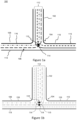
- Figure 1a schematically shows a cross-sectional view of an example composite component 100, comprising a compound member 102 extending from a junction 104 with a feeder member 106.
- the example composite component 100 is in the form of a T-piece, with the compound member 102 extending substantially orthogonally with respect to the feeder member 106 but it will be appreciated that other configurations are possible and envisaged in the context of the present invention.
- the compound member extends from a junction 104 mid-way along the feeder member.
- the feeder member 106 has first and second feeder portions 108, 110 disposed either side of the junction 104. Accordingly, the component 100 has a relatively complex shape owing to the joining together of multiple members.
- Figure 1a depicts layers of fibre-reinforcement material, in particular a compound set 112 of warp tows extending from the first and second feeder portions 108, 110 to the compound portion 102. As shown in Figure 1a , some of the warp tows of the compound set 112 extend from the first feeder portion into the compound member 102 via the junction 104, whereas others extend from the second feeder portion into the compound member 102 via the junction 104.
- the inventors have determined that it can be advantageous to bind a noodle element 114 within the woven structure as shown in Figure 1a .
- the noodle element can be bound within the woven structure.
- the noodle element 114 acts as a guide for the profile of the woven structure, in particular by defining a specific location at which the tows are to turn along the lateral extent of the preform. Accordingly, a noodle may be inserted to not only reinforce and increase the fibre volume fraction at a junction, but also to ensure compliance with the intended location of the junction and where the fibre reinforcement material is to turn from the feeder member to the compound member.
- each compound tow is a crossing tow, but in other examples the set of compound tows may comprise warp tows which do not cross with a corresponding tow from the opposing feeder portion.
- the crossing tows pass on two opposing sides of the noodle element 114 to define an "eye" 115 (i.e. a passageway delimited by the crossing tows) through which the noodle element extends.
- the component 100 has a base side extending between the feeder portions 108, 110 and distal to the compound member (i.e. away from the compound member) and a compound side at an interface between the junction and the compound member.
- the noodle element 114 is located in an eye 115 defined by the crossing set of warp tows, including warp tows from the first feeder portion that extend past the noodle on both the base side and the compound side, and warp tows from the second feeder portion that extend past the noodle on both the base side and the compound side.
- Figure 1a is a simplified example and there may be more layers of fibre-reinforcement material which together define more eyes for noodle elements, and a junction may comprise one or more than one noodle elements extending through respective eyes.
- a junction may comprise one or more than one noodle elements extending through respective eyes.
- Figure 1b A variant example substantially as described above with respect to Figure 1a , but comprising two noodle elements 114, 114' in respective eyes 115, 115' is shown in Figure 1b .
- Figure 1b in this example there are commensurately more compound tows 112 which collectively define the eyes 115, 115'.
- the noodle element 114 may comprise a bundle of fibre-reinforcement material.
- the noodle element 114 may have a tow weight (corresponding to a number of fibre filaments) which is greater than a tow weight of the warp tows in the feeder member the compound member.
- the noodle element may comprise a 12k tow (e.g. having a tow weight of 800mg per meter), whereas the warp tows may comprise a 3k tow (e.g. having a tow weight of 200mg per meter).
- the component 100 comprises capping plies 116 extending from the first and second feeder portions 108, 110 to the compound portion 102.
- the capping plies 116 define an outer surface of the component, and do not cross or interlace with the crossing tows described above.
- the capping plies 116 may be applied as a separate layer of the preform from the compound tows 112, or may be formed integrally with the compound tows 112 in a multi-layer weave.
- the component 100 may be provided with a relatively smooth outer profile, particularly at the junction, by overlaying the crossing tows.
- the base ply can provide a relatively smooth outer profile of the component, particularly at the junction where it overlays the crossing tows.
- the base ply is applied as a separate layer of the preform after the compound tows 112 (including crossing tows) are woven to form the crossing structure shown in Figure 1a .
- the capping plies 116 and the base ply may each be either a woven ply (for example a 2D weave, or a multi-layer weave), or a ply of unidirectional fibre-reinforcement material.
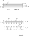
- Figure 2a shows an example woven structure 200 comprising a plurality of warp tows W, B extending along a warp direction P.
- the structure 200 further comprises a plurality of weft tows extending along a weft direction F.
- the woven composite or associated preform comprises two dimensional woven structures (i.e. rather than multi-layer woven structures as also disclosed herein)
- the example of Figure 2 is a multi-layer structure.
- a multi-layer weave there are multiple layers of weft tows extending along a weft direction and layered in a thickness direction of the weave, with warp tows extending along a substantially orthogonal warp direction at respective locations along the weft direction.
- Each location along the weft direction occupied by one or more warp tows superposed on each other through the thickness direction is referred to herein and in the art as a "stack", such that there are a plurality of stacks defined along the weft direction by respective sets of one or more warp tows.
- a common configuration of stacks in a multi-layer weave is to provide an alternating arrangement of warp stacks W and binding stacks B as shown in Figure 2 , with binding stacks being stacks in which the or each warp tow is interlaced with weft tows to bind the weft tows (i.e. moving between layers of weft tows, or moving between warp tow positions defined between such layers), whereas warp stacks are stacks in which the or each warp tow extends without interlacing with weft tows (e.g. remaining between the same two layers of weft tows, or remaining at the same warp tow position).
- Figure 2b shows cross-sectional slices of the woven structure 200 normal to the weft direction F at lateral positions along the weft direction corresponding to a warp stack W and a binding stack B.
- the woven structure is described as a multi-layer woven structure herein as it comprises a plurality of layers of weft tows 202 (shown in cross section) defining a plurality of warp tow positions between the layers of weft tows.
- the warp tows 204 extend along the warp direction at constant warp tow positions (i.e. remaining in the same warp tow position between weft layers).
- a warp tow 204 extends through the thickness direction of the woven structure between opposing sides to define a multi-layer weave pattern.
- the multi-layer weave type is an orthogonal through-thickness weave having a float number of two, meaning that each binding warp tow extends through the thickness from side to side of the woven structure, and passes over two weft tows before returning.
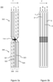
- FIG 3A shows an example woven preform 300 for a warp stack for the example component 100 of Figure 1a , shown in cross-section normal to the weft direction (i.e. in the plane of a thickness direction T and a longitudinal direction).
- the woven preform has a feeder region 306 corresponding to the feeder member 106 of Figure 1a , and a compound region 302 corresponding to the compound member 102 of Figure 1a .
- four warp tow positions are illustrated in each of the regions by boxes, with warp tows 321, 322, 323, 324 extending through adjacent warp tow positions along a thickness direction of the preform that will be referred to herein as warp tow positions 1, 2, 3, 4 respectively.
- the woven preform comprises a plurality of layers of weft tows extending orthogonal to the view of Figure 3 , so as to define the warp tow positions therebetween.
- Figure 3a shows the warp tows 321-324 extending longitudinally along the feeder region 306 until reaching a junction with the compound region 302, where the warp tows are woven around the noodle element 114 as described above with respect to Figure 1a .
- the feeder region 306 comprises two leaves corresponding to the respective feeder portions 108, 110 of the composite component 100 of Figure 1a , with first and second warp tows 321, 322 extending through a first leaf, and third and fourth tows 323, 324 extending through a second leaf in this example.
- the first tow 321 extends from the first warp tow position 1 within the first leaf of the feeder region 306 to the third warp tow position 3 within the compound region 302, passing the noodle element 114 on a side proximal to the compound region 302 (a "compound side” as described above with reference to Figure 1a ), and crossing with third and fourth tows 323, 324 from the second leaf.
- the second tow 322 extends from the second warp tow position 2 within the first leaf of the feeder region 306 to the fourth warp tow position 4 within the compound region 302, passing the noodle element on a side proximal to the feeder region 306 (a "base side” as described above with reference to Figure 1a ), and crossing with third and fourth tows 323, 324 from the second leaf.
- the third tow 323 extends from the third warp tow position 3 within the second leaf of the feeder region 306 to the first warp tow position 1 within the compound region 302, passing the noodle element 114 on a side proximal to the feeder region 306 (the "base side” as described above), and crossing with first and second tows 321, 322 from the first leaf.
- the fourth tow 324 extends from the fourth warp tow position 4 within the second leaf to the second warp tow position 2 within the compound region 302, passing the noodle element 114 on a side proximal to the compound region 302 (the "compound side” as described above), and crossing with first and second tows 321, 322 from the first leaf.
- the above example illustrates how crossing tows passing each other and around the noodle element can together define an eye for the noodle element to pass through.
- the expression “leaf” is used with respect to the two leaves of the feeder region 306 because these two separate portions are separable from one another away from the junction, so as to form a feeder member 106 as described above with respect to Figure 1a .
- binding warp tows in binding stacks of the weave in the feeder region n306 may only extend between warp tow positions associated with the respective leaf, such that the leaves remain separable.
- warp tows e.g. the same warp tows
- the warp tows 321-324 that cross each other are located in the same stack, such that away from the junction they are superposed on one another along the thickness direction. Accordingly, it should be appreciated that the crossing of the warp tows necessitates a lateral deflection of the warp tows at the point of crossing. It is thought that this can be accommodated owing to the generally lower fibre volume fraction in the location of the junction in the formed component 100, where two feeder portions of relatively low thickness combine to provide a compound tow having a greater thickness.
- each individual stack in a multi-layer weave need not have a quantity of warp tows sufficient for defining an eye for the noodle - i.e. with warp tows from both leaves extending past the noodle on both the compound and base sides, crossing with the respective other tows to define the noodle.
- the eye for the noodle may be cumulatively defined by several stacks of the weave.
- some stacks may comprise fewer warp tows than the minimum of four required to create the structure defined above.
- Figure 3b shows four laterally adjacent stacks A, B, C, D over a longitudinal extent corresponding to that shown in Figure 3a , and with a longitudinal position corresponding to the crossing location and noodle indicated in hatching.
- tows corresponding to the four tows 1-4 of Figure 3a which collectively define the eye around the noodle element 114 are located in different stacks of the multi-layer weave, with tows 1-4 in stacks A-D respectively.
- two or more (or all) of the respective tows defining the eye may be located in the same stack.
- the stacks in the weave comprise warp tows configured to define an eye around the noodle within the stack itself.
- Figure 3a does not show features of a multi-layer weave away from the junction, this is because it depicts an example warp stack in which the warp tows extend generally longitudinally within respective warp tow positions, without inter-layer weaving.
- one or more warp tows may extend between warp tow positions within the feeder region 306 (e.g. within the respective leaf of the feeder region) and/or the compound region 302 to define a multi-layer weave.
- the weave may comprise a layer-to-layer angle interlock weave, a through-thickness angle interlock weave, or an orthogonal through-thickness weave, all of which are terms of the art.
- a method of manufacturing a preform for a woven composite component will now be described with reference to the preform 300 of Figure 3a .
- the method comprises weaving a preform as described above with respect to Figure 3a , and subsequently separating the feeder leaves of the feeder region, for subsequently forming a composite component having respective feeder portions 108, 110 as described above with respect to Figure 1a . Separation of the leaves simply refers to re-orienting them to extend away from the junction in a manner corresponding to the arrangement of the feeder portions 108, 110 as shown in Figure 1a .
- the preform can be woven using a loom configured to receive warp tows from a warp tow supply, and configured to weave the warp tows around weft tows inserted along the weft direction as is known in the art.
- the loom may be of any suitable type as is known in the art.
- the loom may be programmable (i.e. configured for computer control) to form the woven preform with weave patterns based on computerreadable instructions.
- Such a loom may be referred to as a computer-controlled jacquard loom.
- a loom can be controlled to separate respective sets of warp tows to define an opening for insertion of a weft tow between them.
- a set of warp tows may be lifted to an upper side of the opening so as to pass over the weft tow, whereas another set may extend below the opening so as to pass under the weft tow.
- the same or different sets of warp tows can then be repositioned to define another opening for reception of a weft tow.
- the loom may be controlled so that a first subset of the crossing tows 112 are caused to cross each other along the thickness direction (e.g. by drawing a warp tow from a relatively higher warp tow position to an underside of an opening in the loom, and drawing a warp tow from a relatively lower warp tow position to an upper side of the opening) prior to insertion of the noodle element.
- the noodle element may then be received in the loom adjacent to the crossing tows (e.g. in the opening between them).
- a second subset of crossing tows may be caused to cross each other, for example by drawing a warp tow extending around an upper side of the noodle element to a relatively lower warp tow position, and by drawing a warp tow extending around a lower side of the noodle element to a relatively higher warp tow position. Accordingly, the first and second subsets of crossing tows can be oriented around the noodle element to define an eye for the noodle element as discussed herein.
- the preform may be transferred to a die or mould which defines a near net shape for the component, and a matrix material (such as a resin, for example epoxy resin) can be transferred to the die or mould.
- a matrix material such as a resin, for example epoxy resin
- the matrix material and fibre-reinforcement can then be cured (for example under elevated temperature and/or pressure) to provide the formed composite component.
- a suitable fibre-reinforcement material for any reform or component disclosed herein may be carbon fibre, but it will be appreciated that any suitable fibre reinforcement material can be used.
- Figure 4 shows an I-beam structure 400 that has two feeder members at either end of a compound member 402, each feeder member having respective first and second feeder portions 408, 410.
- the I-beam structure may be formed from a preform having a compound region with two feeder regions at either end, with respective junctions comprising noodle elements therebetween as discussed above.
- a further example composite component 500 is shown in Figure 5 .
- the component 500 is a twin-vane section for a gas turbine engine, having compound members 502 and feed members (having feeder portions 508, 510) as described above forming aerodynamic vanes and platforms respectively. While shown schematically in Figure 5 , the component 500 may be semi-annular for integration into an annular ring of like components disposed around a central axis.
- the platforms formed of the feeder portions 508, 510 may extend substantially circumferentially, whereas the vanes formed of the compound members 502 may extend substantially radially.
- the component 500 has a construction corresponding to two I-beams (such as those described above with respect to Figure 4 ) having joined feeder portions 508, 510.
- Figure 5 shows join locations 520 where a join may be provided between feeder portions 508, 510 associated with respective compound members 502.
- Such a join may be formed by base and capping plies as described herein, in addition to other known joining methods such as through-thickness stitching, tufting.
- a further method of joining at a join location may be to provide the respective feeder portions with a tapering profile in which layers of the multi-layer structure terminate at staggered positions along the elongate extent of the portion. For example, an offset between terminal positions of layers may be approximately 25mm.
- layers may progressively terminate at positions 6.25mm apart to form a tapered profile over a 25mm longitudinal extent.
- the opposing feeder portion for the join may be provided with a corresponding tapered profile and the two may be overlayed for joining, for example in a subsequent resin transfer process and by any of the joining methods discussed above.
- Capping or base plies as described herein may be extended over the join for improved structural integrity and load transfer.
- T-piece, I-beam and twin-vane components are exemplary only and the concepts of the invention apply to all components having a member that extends from a junction with one or more other members/portions, such that fibre reinforcement material extends into a compound member of the component from two (or more) feeder portions of the component.
- Other example components include rotor discs, support structures, spars, stringers, support beams, ribs, whether for use in an aerospace apparatus or machine (e.g. an airframe or a propulsion device such as a gas turbine engine) or for other (non-aerospace) uses.
Landscapes
- Engineering & Computer Science (AREA)
- Textile Engineering (AREA)
- Mechanical Engineering (AREA)
- Chemical & Material Sciences (AREA)
- Composite Materials (AREA)
- Woven Fabrics (AREA)
Abstract
Description
- The invention concerns a woven composite component having a compound member extending from a junction with a feeder member, with warp tows crossing each other at the junction around a noodle element.
- It is known to use composite materials comprising a matrix reinforced with fibre reinforcement material such as carbon fibre for components to provide a desirable combination of properties, such as strength and low weight.
- It is known to form composite components by providing a lay-up comprising a plurality of plies of fibre reinforcement material, for example over a lay-up surface which defines a profile for the component.
- Woven composite structures have been proposed for use in component manufacture owing to desirable properties relating to structural integrity. However, woven preforms are generally provided in sheets, which may be difficult to use to form a complex shape, such as a shape having multiple members. In particular, there are challenges in joining woven structures at a junction between members.
- According to a first aspect there is disclosed a woven composite component for an aerospace structure or machine, comprising:
- a compound member extending from a junction with a feeder member, a noodle element extending in a weft direction through the junction;
- wherein the feeder member comprises first and second feeder portions either side of the junction, each feeder portion comprising warp tows extending towards the junction;
- wherein there is a compound set of warp tows extending from the first and second feeder portions, each turning at the junction to define warp tows for the compound member;
- wherein, there is a crossing set of warp tows belonging to the compound set, the crossing set comprising warp tows from the first feeder portion and warp tows from the second portion which cross each other at the junction to pass around the noodle element.
- It may be that the junction has a base side extending between the feeder portions and distal to the compound member, and a compound side at an interface between the junction and the compound member. It may be that the noodle element is located in an eye defined by the crossing set of warp tows, including warp tows from the first feeder portion that extend past the noodle on both the base side and the compound side; and warp tows from the second feeder portion that extend past the noodle on both the base side and the compound side.
- It may be that the component comprises a plurality of noodle elements extending in the weft direction through the junction, each located in a respective eye defined by the crossing set of warp tows, including warp tows from the first feeder portion that extend past the noodle on both the base side and the compound side; and warp tows from the second feeder portion that extend past the noodle on both the base side and the compound side.
- It may be that the first and second feeder portions each have a plurality of layers of weft tows through a thickness of the respective portion, defining therebetween warp tow depth positions. It may be that, for the or each noodle: (i) warp tows of the crossing set extend past the respective noodle to define the respective eye from at least two warp tow depth positions in the first feeder portion; and/or (ii) the warp tows of the crossing set extend past the respective noodle to define the respective eye extend from at least two warp tow depth positions in the second feeder portion.
- The first feeder portion and/or the second feeder portion and/or the compound member may comprise a multi-layer weave. The or each multi-layer weave may selected from the group consisting of an angle interlock through-thickness weave, an angle interlock layer-to-layer weave; an orthogonal through-thickness weave and an orthogonal layer-to-layer weave.
- The noodle may comprise a bundle of fibre-reinforcement material. A tow weight of the noodle may be greater than an average tow weight of weft tows in the composite component.
- It may be that the feeder member is provided with one or more base plies of fibre reinforcement material extending from the first feeder portion to the second feeder portion, wherein the one or more base plies are not interwoven with the compound set.
- The woven composite component may comprise one or more capping plies, each of which: (i) forms part of the first feeder portion and part of a respective side of the compound member, wherein warp tows of the capping ply do not belong to the crossing set of warp tows; or (ii) forms part of the second feeder portion and part of a respective side of the compound member, wherein warp tows of the capping ply do not belong to the crossing set of warp tows.
- It may be that one or more of the capping plies forms part of a multi-layer weave of the respective feeder portion and the compound member.
- It may be that the compound member extends between two opposing feeder members, each feeder member having first and second feeder portions
- It may be that the component is of a type selected from the group consisting of: (i) a T-beam, (ii) an I beam (also known as an H-beam) and (iii) a vane or rotor section for a gas turbine engine, comprising a vane or rotor respectively defined by the compound member and one or more platforms defined by the or each feeder member.
- According to a second aspect there is disclosed a method of manufacturing a preform for a woven composite component in accordance with any preceding claim, the method comprising weaving a multi-layer woven preform comprising:
- a compound region corresponding to the member of the composite component; and
- a feeder region corresponding to the feeder member and comprising first and second non-interwoven leaves which are superposed with respect to a thickness direction of the preform during weaving;
- a junction between the feeder region and the compound region, comprising a noodle element extending along a weft direction of the woven preform
- wherein a compound set of warp tows extend from the first and second leaves, including a crossing set of warp tows which cross each other at the junction to pass around the noodle element;
- separating the first and second leaves of the feeder region for forming the feeder member of the composite component.
- The method may comprise: prior to insertion of the noodle element in the woven preform, causing a first subset of the crossing tows to cross each other along the thickness direction on a first side of the noodle with respect to a warp direction of the woven preform. The method may comprise inserting the noodle element into the woven preform along the weft direction. The method may comprise, after inserting the noodle element, causing a second subset of the crossing tows to cross each other along the thickness direction on a second side of the noodle with respect to the warp direction. Thereby the noodle element may be captured in an eye defined by the crossing tows.
- Embodiments will now be described by way of example only with reference to the accompanying drawings, which are purely schematic and not to scale, and in which:
-
Figure 1a and 1b schematically shows cross-sections through woven composite components; -
Figure 2 schematically shows a cross-section through a woven preform for a composite component; -
Figure 3a and 3b schematically show members of an example woven composite component; -
Figure 4 schematically shows a further example woven composite component; and -
Figure 5 schematically shows an example composite component. -
Figure 1a schematically shows a cross-sectional view of anexample composite component 100, comprising acompound member 102 extending from ajunction 104 with afeeder member 106. As illustrated, theexample composite component 100 is in the form of a T-piece, with thecompound member 102 extending substantially orthogonally with respect to thefeeder member 106 but it will be appreciated that other configurations are possible and envisaged in the context of the present invention. - Rather than being arranged contiguously end-to-end such that fibre-reinforcement material can extend straightforwardly into the
compound member 102 from the feeder member, the compound member extends from ajunction 104 mid-way along the feeder member. Thefeeder member 106 has first andsecond feeder portions junction 104. Accordingly, thecomponent 100 has a relatively complex shape owing to the joining together of multiple members. -
Figure 1a depicts layers of fibre-reinforcement material, in particular a compound set 112 of warp tows extending from the first andsecond feeder portions compound portion 102. As shown inFigure 1a , some of the warp tows of the compound set 112 extend from the first feeder portion into thecompound member 102 via thejunction 104, whereas others extend from the second feeder portion into thecompound member 102 via thejunction 104. - Owing to the turning of the tows at the
junction 104, there can be a reduction in fibre volume fraction within a formed composite component. For this reason, it has previously been considered to provide additional fibre reinforcement material at the junction in the form of a noodle element at the junction, for example comprising a bundle of fibre-reinforcement material. Such previous attempts have provided the noodle element in a central location of the junction, with two effectively separate sets of plies extending around the noodle on different sides. - However, the inventors have determined that in such arrangements the noodle element is poorly integrated with the woven structure in its preform state, therefore leading to difficulties in handing and manipulating the preform ready for forming a composite component.
- According to the present invention, the inventors have determined that it can be advantageous to bind a
noodle element 114 within the woven structure as shown inFigure 1a . In particular, by causing the compound tows extending fromopposing feeder portions noodle element 114, thenoodle element 114 acts as a guide for the profile of the woven structure, in particular by defining a specific location at which the tows are to turn along the lateral extent of the preform. Accordingly, a noodle may be inserted to not only reinforce and increase the fibre volume fraction at a junction, but also to ensure compliance with the intended location of the junction and where the fibre reinforcement material is to turn from the feeder member to the compound member. - As shown in
Figure 1a , there are several layers of warp tows through a thickness direction in each of the first andsecond feeder portions noodle element 114. In the example ofFigure 1a , each compound tow is a crossing tow, but in other examples the set of compound tows may comprise warp tows which do not cross with a corresponding tow from the opposing feeder portion. - In the particular example shown in
Figure 1a , the crossing tows pass on two opposing sides of thenoodle element 114 to define an "eye" 115 (i.e. a passageway delimited by the crossing tows) through which the noodle element extends. In particular, thecomponent 100 has a base side extending between thefeeder portions noodle element 114 is located in aneye 115 defined by the crossing set of warp tows, including warp tows from the first feeder portion that extend past the noodle on both the base side and the compound side, and warp tows from the second feeder portion that extend past the noodle on both the base side and the compound side. - It should be appreciated that
Figure 1a is a simplified example and there may be more layers of fibre-reinforcement material which together define more eyes for noodle elements, and a junction may comprise one or more than one noodle elements extending through respective eyes. A variant example substantially as described above with respect toFigure 1a , but comprising twonoodle elements 114, 114' inrespective eyes 115, 115' is shown inFigure 1b . As shown inFigure 1b , in this example there are commensurately morecompound tows 112 which collectively define theeyes 115, 115'. As stated above, thenoodle element 114 may comprise a bundle of fibre-reinforcement material. Thenoodle element 114 may have a tow weight (corresponding to a number of fibre filaments) which is greater than a tow weight of the warp tows in the feeder member the compound member. For example, the noodle element may comprise a 12k tow (e.g. having a tow weight of 800mg per meter), whereas the warp tows may comprise a 3k tow (e.g. having a tow weight of 200mg per meter). - As shown in
Figure 1a , thecomponent 100 comprises capping plies 116 extending from the first andsecond feeder portions compound portion 102. The capping plies 116 define an outer surface of the component, and do not cross or interlace with the crossing tows described above. The capping plies 116 may be applied as a separate layer of the preform from the compound tows 112, or may be formed integrally with the compound tows 112 in a multi-layer weave. By providing the capping plies, thecomponent 100 may be provided with a relatively smooth outer profile, particularly at the junction, by overlaying the crossing tows. - As further shown in
Figure 1a , there is abase ply 118 extending from thefirst feeder portion 108 to thesecond feeder portion 110 and defining an outer surface of the feeder member on a side opposite thecompound member 102. As with the capping plies 116, the base ply can provide a relatively smooth outer profile of the component, particularly at the junction where it overlays the crossing tows. In manufacturing, the base ply is applied as a separate layer of the preform after the compound tows 112 (including crossing tows) are woven to form the crossing structure shown inFigure 1a . The capping plies 116 and the base ply may each be either a woven ply (for example a 2D weave, or a multi-layer weave), or a ply of unidirectional fibre-reinforcement material. - To aid the further discussion of multi-layer weaves, selected weave terminology is discussed below with reference to
Figure 2 (comprisingFigures 2a and 2b). Figure 2a shows an examplewoven structure 200 comprising a plurality of warp tows W, B extending along a warp direction P. Although not shown, thestructure 200 further comprises a plurality of weft tows extending along a weft direction F. Although the invention extends to examples in which the woven composite or associated preform comprises two dimensional woven structures (i.e. rather than multi-layer woven structures as also disclosed herein), the example ofFigure 2 is a multi-layer structure. In a multi-layer weave, there are multiple layers of weft tows extending along a weft direction and layered in a thickness direction of the weave, with warp tows extending along a substantially orthogonal warp direction at respective locations along the weft direction. Each location along the weft direction occupied by one or more warp tows superposed on each other through the thickness direction is referred to herein and in the art as a "stack", such that there are a plurality of stacks defined along the weft direction by respective sets of one or more warp tows. A common configuration of stacks in a multi-layer weave is to provide an alternating arrangement of warp stacks W and binding stacks B as shown inFigure 2 , with binding stacks being stacks in which the or each warp tow is interlaced with weft tows to bind the weft tows (i.e. moving between layers of weft tows, or moving between warp tow positions defined between such layers), whereas warp stacks are stacks in which the or each warp tow extends without interlacing with weft tows (e.g. remaining between the same two layers of weft tows, or remaining at the same warp tow position). -
Figure 2b shows cross-sectional slices of the wovenstructure 200 normal to the weft direction F at lateral positions along the weft direction corresponding to a warp stack W and a binding stack B. The woven structure is described as a multi-layer woven structure herein as it comprises a plurality of layers of weft tows 202 (shown in cross section) defining a plurality of warp tow positions between the layers of weft tows. As shown inFigure 2b , in the warp stack W the warp tows 204 extend along the warp direction at constant warp tow positions (i.e. remaining in the same warp tow position between weft layers). In contrast, in the binding stack B awarp tow 204 extends through the thickness direction of the woven structure between opposing sides to define a multi-layer weave pattern. In this particular example, the multi-layer weave type is an orthogonal through-thickness weave having a float number of two, meaning that each binding warp tow extends through the thickness from side to side of the woven structure, and passes over two weft tows before returning. -
Figure 3A shows an example wovenpreform 300 for a warp stack for theexample component 100 ofFigure 1a , shown in cross-section normal to the weft direction (i.e. in the plane of a thickness direction T and a longitudinal direction). The woven preform has afeeder region 306 corresponding to thefeeder member 106 ofFigure 1a , and acompound region 302 corresponding to thecompound member 102 ofFigure 1a . By way of simplified example, four warp tow positions are illustrated in each of the regions by boxes, withwarp tows warp tow positions Figure 3 , so as to define the warp tow positions therebetween. -
Figure 3a shows the warp tows 321-324 extending longitudinally along thefeeder region 306 until reaching a junction with thecompound region 302, where the warp tows are woven around thenoodle element 114 as described above with respect toFigure 1a . As shown by the dashed lines separately circumscribing tow positions 1 and 2 (together) and 3 and 4 (together), thefeeder region 306 comprises two leaves corresponding to therespective feeder portions composite component 100 ofFigure 1a , with first and second warp tows 321, 322 extending through a first leaf, and third andfourth tows - The
first tow 321 extends from the first warp tow position 1 within the first leaf of thefeeder region 306 to the thirdwarp tow position 3 within thecompound region 302, passing thenoodle element 114 on a side proximal to the compound region 302 (a "compound side" as described above with reference toFigure 1a ), and crossing with third andfourth tows - The
second tow 322 extends from the secondwarp tow position 2 within the first leaf of thefeeder region 306 to the fourthwarp tow position 4 within thecompound region 302, passing the noodle element on a side proximal to the feeder region 306 (a "base side" as described above with reference toFigure 1a ), and crossing with third andfourth tows - The
third tow 323 extends from the thirdwarp tow position 3 within the second leaf of thefeeder region 306 to the first warp tow position 1 within thecompound region 302, passing thenoodle element 114 on a side proximal to the feeder region 306 (the "base side" as described above), and crossing with first andsecond tows - The
fourth tow 324 extends from the fourthwarp tow position 4 within the second leaf to the secondwarp tow position 2 within thecompound region 302, passing thenoodle element 114 on a side proximal to the compound region 302 (the "compound side" as described above), and crossing with first andsecond tows - The expression "leaf" is used with respect to the two leaves of the
feeder region 306 because these two separate portions are separable from one another away from the junction, so as to form afeeder member 106 as described above with respect toFigure 1a . In particular, it will be appreciated that in a multi-layer weave structure, binding warp tows in binding stacks of the weave in the feeder region n306 may only extend between warp tow positions associated with the respective leaf, such that the leaves remain separable. In contrast, warp tows (e.g. the same warp tows) may extend to other warp tow positions or throughout a thickness of the weave in the compound region. - In the example described above with respect to
Figure 3a , the warp tows 321-324 that cross each other are located in the same stack, such that away from the junction they are superposed on one another along the thickness direction. Accordingly, it should be appreciated that the crossing of the warp tows necessitates a lateral deflection of the warp tows at the point of crossing. It is thought that this can be accommodated owing to the generally lower fibre volume fraction in the location of the junction in the formedcomponent 100, where two feeder portions of relatively low thickness combine to provide a compound tow having a greater thickness. - It should be appreciated that each individual stack in a multi-layer weave need not have a quantity of warp tows sufficient for defining an eye for the noodle - i.e. with warp tows from both leaves extending past the noodle on both the compound and base sides, crossing with the respective other tows to define the noodle. Instead, the eye for the noodle may be cumulatively defined by several stacks of the weave. In particular, some stacks may comprise fewer warp tows than the minimum of four required to create the structure defined above. By way of example,
Figure 3b shows four laterally adjacent stacks A, B, C, D over a longitudinal extent corresponding to that shown inFigure 3a , and with a longitudinal position corresponding to the crossing location and noodle indicated in hatching. In the variant example ofFigure 3b , tows corresponding to the four tows 1-4 ofFigure 3a which collectively define the eye around thenoodle element 114 are located in different stacks of the multi-layer weave, with tows 1-4 in stacks A-D respectively. In other examples, two or more (or all) of the respective tows defining the eye may be located in the same stack. - Nevertheless, it may be that in some examples, at least some of the stacks in the weave comprise warp tows configured to define an eye around the noodle within the stack itself. Although
Figure 3a does not show features of a multi-layer weave away from the junction, this is because it depicts an example warp stack in which the warp tows extend generally longitudinally within respective warp tow positions, without inter-layer weaving. However, it should be appreciated that in binding stacks one or more warp tows may extend between warp tow positions within the feeder region 306 (e.g. within the respective leaf of the feeder region) and/or thecompound region 302 to define a multi-layer weave. For example, in binding stacks the weave may comprise a layer-to-layer angle interlock weave, a through-thickness angle interlock weave, or an orthogonal through-thickness weave, all of which are terms of the art. - A method of manufacturing a preform for a woven composite component will now be described with reference to the
preform 300 ofFigure 3a . The method comprises weaving a preform as described above with respect toFigure 3a , and subsequently separating the feeder leaves of the feeder region, for subsequently forming a composite component havingrespective feeder portions Figure 1a . Separation of the leaves simply refers to re-orienting them to extend away from the junction in a manner corresponding to the arrangement of thefeeder portions Figure 1a . - The preform can be woven using a loom configured to receive warp tows from a warp tow supply, and configured to weave the warp tows around weft tows inserted along the weft direction as is known in the art. The loom may be of any suitable type as is known in the art. For complex weaves, the loom may be programmable (i.e. configured for computer control) to form the woven preform with weave patterns based on computerreadable instructions. Such a loom may be referred to as a computer-controlled jacquard loom.
- As is known in the art, a loom can be controlled to separate respective sets of warp tows to define an opening for insertion of a weft tow between them. For example, a set of warp tows may be lifted to an upper side of the opening so as to pass over the weft tow, whereas another set may extend below the opening so as to pass under the weft tow. After insertion of the weft tow, the same or different sets of warp tows can then be repositioned to define another opening for reception of a weft tow.
- To form the
woven preform 300 as described above, the loom may be controlled so that a first subset of the crossing tows 112 are caused to cross each other along the thickness direction (e.g. by drawing a warp tow from a relatively higher warp tow position to an underside of an opening in the loom, and drawing a warp tow from a relatively lower warp tow position to an upper side of the opening) prior to insertion of the noodle element. The noodle element may then be received in the loom adjacent to the crossing tows (e.g. in the opening between them). After inserting the noodle element, a second subset of crossing tows may be caused to cross each other, for example by drawing a warp tow extending around an upper side of the noodle element to a relatively lower warp tow position, and by drawing a warp tow extending around a lower side of the noodle element to a relatively higher warp tow position. Accordingly, the first and second subsets of crossing tows can be oriented around the noodle element to define an eye for the noodle element as discussed herein. - To form a composite component from the preform, the preform may be transferred to a die or mould which defines a near net shape for the component, and a matrix material (such as a resin, for example epoxy resin) can be transferred to the die or mould. The matrix material and fibre-reinforcement can then be cured (for example under elevated temperature and/or pressure) to provide the formed composite component. A suitable fibre-reinforcement material for any reform or component disclosed herein may be carbon fibre, but it will be appreciated that any suitable fibre reinforcement material can be used.
- While the
composite component 100 ofFigure 1a has a T-piece configuration, as does the associatedwoven preform 300 ofFigure 3a , it should be appreciated that a component comprising a compound member and feeder member as described herein can take any suitable shape. - Merely as a further example,
Figure 4 shows an I-beam structure 400 that has two feeder members at either end of acompound member 402, each feeder member having respective first andsecond feeder portions - A further example
composite component 500 is shown inFigure 5 . Thecomponent 500 is a twin-vane section for a gas turbine engine, havingcompound members 502 and feed members (havingfeeder portions 508, 510) as described above forming aerodynamic vanes and platforms respectively. While shown schematically inFigure 5 , thecomponent 500 may be semi-annular for integration into an annular ring of like components disposed around a central axis. The platforms formed of thefeeder portions compound members 502 may extend substantially radially. - The
component 500 has a construction corresponding to two I-beams (such as those described above with respect toFigure 4 ) having joinedfeeder portions Figure 5 shows joinlocations 520 where a join may be provided betweenfeeder portions respective compound members 502. Such a join may be formed by base and capping plies as described herein, in addition to other known joining methods such as through-thickness stitching, tufting. A further method of joining at a join location may be to provide the respective feeder portions with a tapering profile in which layers of the multi-layer structure terminate at staggered positions along the elongate extent of the portion. For example, an offset between terminal positions of layers may be approximately 25mm. For example, in a 5 layer structure layers may progressively terminate at positions 6.25mm apart to form a tapered profile over a 25mm longitudinal extent. The opposing feeder portion for the join may be provided with a corresponding tapered profile and the two may be overlayed for joining, for example in a subsequent resin transfer process and by any of the joining methods discussed above. Capping or base plies as described herein may be extended over the join for improved structural integrity and load transfer. - Although the examples of the invention refer to T-piece, I-beam and twin-vane components, it should be appreciated that these are exemplary only and the concepts of the invention apply to all components having a member that extends from a junction with one or more other members/portions, such that fibre reinforcement material extends into a compound member of the component from two (or more) feeder portions of the component. Other example components include rotor discs, support structures, spars, stringers, support beams, ribs, whether for use in an aerospace apparatus or machine (e.g. an airframe or a propulsion device such as a gas turbine engine) or for other (non-aerospace) uses.
Claims (15)
- A woven composite component (100) for an aerospace structure or machine, comprising:a compound member (102) extending from a junction (104) with a feeder member (106), a noodle element (114) extending in a weft direction (F) through the junction (104);wherein the feeder member (106) comprises first and second feeder portions (108,110) either side of the junction (104), each feeder portion (108,110) comprising warp tows extending towards the junction (104);wherein there is a compound set (112) of warp tows extending from the first and second feeder portions (108, 110), each turning at the junction (104) to define warp tows for the compound member (102); andwherein, there is a crossing set of warp tows belonging to the compound set (112), the crossing set comprising warp tows from the first feeder portion (108) and warp tows from the second portion (110) which cross each other at the junction (104) to pass around the noodle element (114).
- The woven composite component (100) according to claim 1, wherein the junction (104) has a base side extending between the feeder portions (108, 110) and distal to the compound member (102), and a compound side at an interface between the junction (104) and the compound member (102); and
wherein the noodle element (114) is located in an eye (115) defined by the crossing set of warp tows, including warp tows from the first feeder portion (108) that extend past the noodle (114) on both the base side and the compound side; and warp tows from the second feeder portion (110) that extend past the noodle on both the base side and the compound side. - The woven composite component (100) according to claim 2, comprising a plurality of noodle elements (114, 114') extending in the weft direction through the junction (104), each located in a respective eye (115, 115') defined by the crossing set of warp tows, including warp tows from the first feeder portion (108) that extend past the noodle (114, 114') on both the base side and the compound side; and warp tows from the second feeder portion (110) that extend past the noodle (114, 114') on both the base side and the compound side.
- The woven composite component (100) according to claim 2 or 3, wherein the first and second feeder portions (108, 110) each have a plurality of layers of weft tows through a thickness of the respective portion, defining therebetween warp tow depth positions; and
wherein, for the or each noodle (114, 114'):warp tows of the crossing set extend past the respective noodle (114, 114') to define the respective eye from at least two warp tow depth positions in the first feeder portion; and/orthe warp tows of the crossing set extend past the respective noodle (114, 114') to define the respective eye extend from at least two warp tow depth positions in the second feeder portion. - The woven composite component (100) according to any preceding claim, wherein the first feeder portion (108) and/or the second feeder portion (110) and/or the compound member (102) comprises a multi-layer weave.
- The woven composite component (100) according to claim 5, wherein the or each multi-layer weave is selected from the group consisting of an angle interlock through-thickness weave, an angle interlock layer-to-layer weave; an orthogonal through-thickness weave and an orthogonal layer-to-layer weave.
- The woven composite component (100) according to any preceding claim, wherein the noodle (114) comprises a bundle of fibre-reinforcement material.
- The woven composite component (100) according to claim 7, wherein a tow weight of the noodle (114) is greater than an average tow weight of weft tows in the composite component (100).
- The woven composite component (100) according to any preceding claim, wherein the feeder member (106) is provided with one or more base plies of fibre reinforcement material extending from the first feeder portion (108) to the second feeder portion (110), wherein the one or more base plies are not interwoven with the compound set (112).
- The woven composite component (100) according to any preceding claim, comprising one or more capping plies (116), each of which:forms part of the first feeder portion (108) and part of a respective side of the compound member, wherein warp tows of the capping ply (116) do not belong to the crossing set of warp tows; orforms part of the second feeder portion (110) and part of a respective side of the compound member, wherein warp tows of the capping ply (116) do not belong to the crossing set of warp tows.
- The woven composite component (100) according to claim 10, wherein one or more of the capping plies (116) forms part of a multi-layer weave of the respective feeder portion and the compound member (102).
- The woven composite component (100) according to any preceding claim, wherein the compound member (102) extends between two opposing feeder members, each feeder member having first and second feeder portions
- The woven composite component (100) according to any preceding claim, wherein the component (100) is of a type selected from the group consisting of:a T-beam;and I beam or H-beam;a vane or rotor section for a gas turbine engine, comprising a vane or rotor respectively defined by the compound member and one or more platforms defined by the or each feeder member.
- A method of manufacturing a preform (300) for a woven composite component (100) in accordance with any preceding claim, the method comprising weaving a multi-layer woven preform comprising:a compound region (302) corresponding to the member (102) of the composite component (100); anda feeder region (306) corresponding to the feeder member (106) and comprising first and second non-interwoven leaves which are superposed with respect to a thickness direction of the preform (300) during weaving;a junction between the feeder region (306) and the compound region (302), comprising a noodle element (114) extending along a weft direction of the woven preformwherein a compound set of warp tows extend from the first and second leaves, including a crossing set of warp tows which cross each other at the junction to pass around the noodle element;separating the first and second leaves of the feeder region (306) for forming the feeder member of the composite component.
- The method according to claim 14, comprising:prior to insertion of the noodle element (114) in the woven preform (300), causing a first subset of the crossing tows to cross each other along the thickness direction on a first side of the noodle (114) with respect to a warp direction of the woven preform (300);inserting the noodle element (114) into the woven preform (300) along the weft direction; andafter inserting the noodle element (300), causing a second subset of the crossing tows to cross each other along the thickness direction on a second side of the noodle (114) with respect to the warp direction;thereby capturing the noodle element (114) in an eye defined by the crossing tows.
Applications Claiming Priority (1)
| Application Number | Priority Date | Filing Date | Title |
|---|---|---|---|
| GBGB2210820.3A GB202210820D0 (en) | 2022-07-25 | 2022-07-25 | Composite component, method of manufacturing a preform for the component |
Publications (2)
| Publication Number | Publication Date |
|---|---|
| EP4324967A1 true EP4324967A1 (en) | 2024-02-21 |
| EP4324967B1 EP4324967B1 (en) | 2025-09-03 |
Family
ID=84540301
Family Applications (1)
| Application Number | Title | Priority Date | Filing Date |
|---|---|---|---|
| EP23183216.3A Active EP4324967B1 (en) | 2022-07-25 | 2023-07-04 | Composite component, method of manufacturing a preform for the component |
Country Status (3)
| Country | Link |
|---|---|
| US (1) | US12533855B2 (en) |
| EP (1) | EP4324967B1 (en) |
| GB (1) | GB202210820D0 (en) |
Citations (2)
| Publication number | Priority date | Publication date | Assignee | Title |
|---|---|---|---|---|
| US5026595A (en) * | 1989-11-09 | 1991-06-25 | Techniweave, Inc. | Woven gap filler for use in the lay-up of composite plastic structural units |
| US20130094898A1 (en) * | 2011-10-13 | 2013-04-18 | Airbus Operations Gmbh | Component, reinforcement member, structural arrangement, aircraft or spacecraft and method |
Family Cites Families (14)
| Publication number | Priority date | Publication date | Assignee | Title |
|---|---|---|---|---|
| FR2497839A1 (en) | 1981-01-12 | 1982-07-16 | Brochier Fils J | THREE-DIMENSIONAL FABRIC FOR REINFORCING LAMINATE MATERIALS AND SHAPED ELEMENTS OBTAINED FROM SUCH A FABRIC |
| JPH09157993A (en) | 1995-12-01 | 1997-06-17 | Nippon Oil Co Ltd | Three-dimensional fabric with taper |
| US7713893B2 (en) | 2004-12-08 | 2010-05-11 | Albany Engineered Composites, Inc. | Three-dimensional woven integrally stiffened panel |
| US7247212B2 (en) | 2004-12-21 | 2007-07-24 | General Electric Company | Orthogonal weaving for complex shape preforms |
| US8127802B2 (en) | 2008-10-29 | 2012-03-06 | Albany Engineered Composites, Inc. | Pi-preform with variable width clevis |
| FR2940173B1 (en) | 2008-12-23 | 2013-02-08 | Snecma | METHOD FOR MANUFACTURING A SHAPE PIECE THROUGH 3D FABRIC AND SHAPE PIECE THUS OBTAINED |
| US8499450B2 (en) | 2010-01-26 | 2013-08-06 | United Technologies Corporation | Three-dimensionally woven composite blade with spanwise weft yarns |
| FR2982518B1 (en) | 2011-11-15 | 2013-12-20 | Snecma | DESIGN OF A PIECE OF 3D COMPOSITE MATERIAL |
| WO2013088038A2 (en) | 2011-12-14 | 2013-06-20 | Snecma | Fiber structure intended to reinforce composite material parts and including a portion having a reduced thickness |
| US9527248B2 (en) | 2013-03-15 | 2016-12-27 | Seriforge Inc. | Systems for three-dimensional weaving of composite preforms and products with varying cross-sectional topology |
| US9664053B2 (en) | 2014-02-12 | 2017-05-30 | Teledyne Scientific & Imaging, Llc | Integral textile structure for 3-D CMC turbine airfoils |
| CN108474148B (en) * | 2016-01-04 | 2020-07-24 | 阿尔巴尼复合物工程股份有限公司 | Preform with integral gap filler |
| EP3999715A1 (en) | 2019-08-22 | 2022-05-25 | Siemens Energy Global GmbH & Co. KG | Three-dimensional ceramic matrix composite t-joint for airfoils via pin-weaving |
| US11346228B1 (en) | 2021-02-23 | 2022-05-31 | Raytheon Technologies Corporation | Airfoil with flange formed of wishbone-shaped fiber layer structure |
-
2022
- 2022-07-25 GB GBGB2210820.3A patent/GB202210820D0/en not_active Ceased
-
2023
- 2023-07-04 EP EP23183216.3A patent/EP4324967B1/en active Active
- 2023-07-12 US US18/220,932 patent/US12533855B2/en active Active
Patent Citations (2)
| Publication number | Priority date | Publication date | Assignee | Title |
|---|---|---|---|---|
| US5026595A (en) * | 1989-11-09 | 1991-06-25 | Techniweave, Inc. | Woven gap filler for use in the lay-up of composite plastic structural units |
| US20130094898A1 (en) * | 2011-10-13 | 2013-04-18 | Airbus Operations Gmbh | Component, reinforcement member, structural arrangement, aircraft or spacecraft and method |
Also Published As
| Publication number | Publication date |
|---|---|
| GB202210820D0 (en) | 2022-09-07 |
| EP4324967B1 (en) | 2025-09-03 |
| US20240025131A1 (en) | 2024-01-25 |
| US12533855B2 (en) | 2026-01-27 |
Similar Documents
| Publication | Publication Date | Title |
|---|---|---|
| EP2370247B1 (en) | Pi-shaped preform with non-linear legs and method to manufacture it | |
| EP2814648B1 (en) | Pi-shaped preform with bias fibers | |
| KR101615102B1 (en) | - Improved fiber architecture for - preforms | |
| CA2741794C (en) | Pi-preform with variable width clevis and related method of forming | |
| TWI604945B (en) | Woven preform with integral off axis stiffeners | |
| CN101998905A (en) | Multidirectionally reinforced shape woven preforms for composite structures | |
| CN102666050A (en) | Woven preform, composite, and method of making thereof | |
| CN104204320A (en) | Method for producing a one-piece preform for a composite structure | |
| US12533855B2 (en) | Composite component, method of manufacturing a preform for the component | |
| EP4311871B1 (en) | Woven structure and method of manufacture | |
| US20240117533A1 (en) | Woven structure and method of manufacture | |
| WO2011015999A1 (en) | Composite components | |
| GB2620928A (en) | Woven structure and method of manufacture | |
| GB2620929A (en) | Woven structure and method of manufacture | |
| GB2620927A (en) | Woven structure and method of manufacture |
Legal Events
| Date | Code | Title | Description |
|---|---|---|---|
| PUAI | Public reference made under article 153(3) epc to a published international application that has entered the european phase |
Free format text: ORIGINAL CODE: 0009012 |
|
| STAA | Information on the status of an ep patent application or granted ep patent |
Free format text: STATUS: THE APPLICATION HAS BEEN PUBLISHED |
|
| AK | Designated contracting states |
Kind code of ref document: A1 Designated state(s): AL AT BE BG CH CY CZ DE DK EE ES FI FR GB GR HR HU IE IS IT LI LT LU LV MC ME MK MT NL NO PL PT RO RS SE SI SK SM TR |
|
| STAA | Information on the status of an ep patent application or granted ep patent |
Free format text: STATUS: REQUEST FOR EXAMINATION WAS MADE |
|
| 17P | Request for examination filed |
Effective date: 20240606 |
|
| RBV | Designated contracting states (corrected) |
Designated state(s): AL AT BE BG CH CY CZ DE DK EE ES FI FR GB GR HR HU IE IS IT LI LT LU LV MC ME MK MT NL NO PL PT RO RS SE SI SK SM TR |
|
| REG | Reference to a national code |
Ref country code: DE Ref legal event code: R079 Free format text: PREVIOUS MAIN CLASS: D03D0025000000 Ipc: B29C0070220000 Ref country code: DE Ref legal event code: R079 Ref document number: 602023006270 Country of ref document: DE Free format text: PREVIOUS MAIN CLASS: D03D0025000000 Ipc: B29C0070220000 |
|
| GRAP | Despatch of communication of intention to grant a patent |
Free format text: ORIGINAL CODE: EPIDOSNIGR1 |
|
| STAA | Information on the status of an ep patent application or granted ep patent |
Free format text: STATUS: GRANT OF PATENT IS INTENDED |
|
| RIC1 | Information provided on ipc code assigned before grant |
Ipc: D03D 41/00 20060101ALI20250409BHEP Ipc: D03D 25/00 20060101ALI20250409BHEP Ipc: B29D 99/00 20100101ALI20250409BHEP Ipc: B29C 70/22 20060101AFI20250409BHEP |
|
| INTG | Intention to grant announced |
Effective date: 20250428 |
|
| GRAS | Grant fee paid |
Free format text: ORIGINAL CODE: EPIDOSNIGR3 |
|
| P01 | Opt-out of the competence of the unified patent court (upc) registered |
Free format text: CASE NUMBER: APP_24302/2025 Effective date: 20250521 |
|
| GRAA | (expected) grant |
Free format text: ORIGINAL CODE: 0009210 |
|
| STAA | Information on the status of an ep patent application or granted ep patent |
Free format text: STATUS: THE PATENT HAS BEEN GRANTED |
|
| AK | Designated contracting states |
Kind code of ref document: B1 Designated state(s): AL AT BE BG CH CY CZ DE DK EE ES FI FR GB GR HR HU IE IS IT LI LT LU LV MC ME MK MT NL NO PL PT RO RS SE SI SK SM TR |
|
| REG | Reference to a national code |
Ref country code: CH Ref legal event code: EP |
|
| REG | Reference to a national code |
Ref country code: DE Ref legal event code: R096 Ref document number: 602023006270 Country of ref document: DE |
|
| REG | Reference to a national code |
Ref country code: IE Ref legal event code: FG4D |
|
| REG | Reference to a national code |
Ref country code: NL Ref legal event code: MP Effective date: 20250903 |
|
| PG25 | Lapsed in a contracting state [announced via postgrant information from national office to epo] |
Ref country code: NO Free format text: LAPSE BECAUSE OF FAILURE TO SUBMIT A TRANSLATION OF THE DESCRIPTION OR TO PAY THE FEE WITHIN THE PRESCRIBED TIME-LIMIT Effective date: 20251203 |
|
| REG | Reference to a national code |
Ref country code: LT Ref legal event code: MG9D |
|
| PG25 | Lapsed in a contracting state [announced via postgrant information from national office to epo] |
Ref country code: FI Free format text: LAPSE BECAUSE OF FAILURE TO SUBMIT A TRANSLATION OF THE DESCRIPTION OR TO PAY THE FEE WITHIN THE PRESCRIBED TIME-LIMIT Effective date: 20250903 |
|
| PG25 | Lapsed in a contracting state [announced via postgrant information from national office to epo] |
Ref country code: HR Free format text: LAPSE BECAUSE OF FAILURE TO SUBMIT A TRANSLATION OF THE DESCRIPTION OR TO PAY THE FEE WITHIN THE PRESCRIBED TIME-LIMIT Effective date: 20250903 |
|
| PG25 | Lapsed in a contracting state [announced via postgrant information from national office to epo] |
Ref country code: GR Free format text: LAPSE BECAUSE OF FAILURE TO SUBMIT A TRANSLATION OF THE DESCRIPTION OR TO PAY THE FEE WITHIN THE PRESCRIBED TIME-LIMIT Effective date: 20251204 |
|
| PG25 | Lapsed in a contracting state [announced via postgrant information from national office to epo] |
Ref country code: SE Free format text: LAPSE BECAUSE OF FAILURE TO SUBMIT A TRANSLATION OF THE DESCRIPTION OR TO PAY THE FEE WITHIN THE PRESCRIBED TIME-LIMIT Effective date: 20250903 |
|
| PG25 | Lapsed in a contracting state [announced via postgrant information from national office to epo] |
Ref country code: LV Free format text: LAPSE BECAUSE OF FAILURE TO SUBMIT A TRANSLATION OF THE DESCRIPTION OR TO PAY THE FEE WITHIN THE PRESCRIBED TIME-LIMIT Effective date: 20250903 |
|
| PG25 | Lapsed in a contracting state [announced via postgrant information from national office to epo] |
Ref country code: PL Free format text: LAPSE BECAUSE OF FAILURE TO SUBMIT A TRANSLATION OF THE DESCRIPTION OR TO PAY THE FEE WITHIN THE PRESCRIBED TIME-LIMIT Effective date: 20250903 Ref country code: BG Free format text: LAPSE BECAUSE OF FAILURE TO SUBMIT A TRANSLATION OF THE DESCRIPTION OR TO PAY THE FEE WITHIN THE PRESCRIBED TIME-LIMIT Effective date: 20250903 |
|
| PG25 | Lapsed in a contracting state [announced via postgrant information from national office to epo] |
Ref country code: RS Free format text: LAPSE BECAUSE OF FAILURE TO SUBMIT A TRANSLATION OF THE DESCRIPTION OR TO PAY THE FEE WITHIN THE PRESCRIBED TIME-LIMIT Effective date: 20251203 |
|
| PG25 | Lapsed in a contracting state [announced via postgrant information from national office to epo] |
Ref country code: ES Free format text: LAPSE BECAUSE OF FAILURE TO SUBMIT A TRANSLATION OF THE DESCRIPTION OR TO PAY THE FEE WITHIN THE PRESCRIBED TIME-LIMIT Effective date: 20250903 |
|
| REG | Reference to a national code |
Ref country code: AT Ref legal event code: MK05 Ref document number: 1832533 Country of ref document: AT Kind code of ref document: T Effective date: 20250903 |
|
| PG25 | Lapsed in a contracting state [announced via postgrant information from national office to epo] |
Ref country code: NL Free format text: LAPSE BECAUSE OF FAILURE TO SUBMIT A TRANSLATION OF THE DESCRIPTION OR TO PAY THE FEE WITHIN THE PRESCRIBED TIME-LIMIT Effective date: 20250903 |
|
| PG25 | Lapsed in a contracting state [announced via postgrant information from national office to epo] |
Ref country code: SM Free format text: LAPSE BECAUSE OF FAILURE TO SUBMIT A TRANSLATION OF THE DESCRIPTION OR TO PAY THE FEE WITHIN THE PRESCRIBED TIME-LIMIT Effective date: 20250903 |
|
| PG25 | Lapsed in a contracting state [announced via postgrant information from national office to epo] |
Ref country code: AT Free format text: LAPSE BECAUSE OF FAILURE TO SUBMIT A TRANSLATION OF THE DESCRIPTION OR TO PAY THE FEE WITHIN THE PRESCRIBED TIME-LIMIT Effective date: 20250903 |
|
| PG25 | Lapsed in a contracting state [announced via postgrant information from national office to epo] |
Ref country code: IT Free format text: LAPSE BECAUSE OF FAILURE TO SUBMIT A TRANSLATION OF THE DESCRIPTION OR TO PAY THE FEE WITHIN THE PRESCRIBED TIME-LIMIT Effective date: 20250903 |
|
| PG25 | Lapsed in a contracting state [announced via postgrant information from national office to epo] |
Ref country code: IS Free format text: LAPSE BECAUSE OF FAILURE TO SUBMIT A TRANSLATION OF THE DESCRIPTION OR TO PAY THE FEE WITHIN THE PRESCRIBED TIME-LIMIT Effective date: 20260103 |
|
| PG25 | Lapsed in a contracting state [announced via postgrant information from national office to epo] |
Ref country code: PT Free format text: LAPSE BECAUSE OF FAILURE TO SUBMIT A TRANSLATION OF THE DESCRIPTION OR TO PAY THE FEE WITHIN THE PRESCRIBED TIME-LIMIT Effective date: 20260105 Ref country code: CZ Free format text: LAPSE BECAUSE OF FAILURE TO SUBMIT A TRANSLATION OF THE DESCRIPTION OR TO PAY THE FEE WITHIN THE PRESCRIBED TIME-LIMIT Effective date: 20250903 |
|
| PG25 | Lapsed in a contracting state [announced via postgrant information from national office to epo] |
Ref country code: SK Free format text: LAPSE BECAUSE OF FAILURE TO SUBMIT A TRANSLATION OF THE DESCRIPTION OR TO PAY THE FEE WITHIN THE PRESCRIBED TIME-LIMIT Effective date: 20250903 Ref country code: EE Free format text: LAPSE BECAUSE OF FAILURE TO SUBMIT A TRANSLATION OF THE DESCRIPTION OR TO PAY THE FEE WITHIN THE PRESCRIBED TIME-LIMIT Effective date: 20250903 |